EP0130561A2 - Wandverkleidung - Google Patents
Wandverkleidung Download PDFInfo
- Publication number
- EP0130561A2 EP0130561A2 EP84107453A EP84107453A EP0130561A2 EP 0130561 A2 EP0130561 A2 EP 0130561A2 EP 84107453 A EP84107453 A EP 84107453A EP 84107453 A EP84107453 A EP 84107453A EP 0130561 A2 EP0130561 A2 EP 0130561A2
- Authority
- EP
- European Patent Office
- Prior art keywords
- hook
- support
- cladding
- panel
- section
- Prior art date
- Legal status (The legal status is an assumption and is not a legal conclusion. Google has not performed a legal analysis and makes no representation as to the accuracy of the status listed.)
- Granted
Links
- 238000005253 cladding Methods 0.000 claims abstract description 73
- 238000011161 development Methods 0.000 description 1
- 230000018109 developmental process Effects 0.000 description 1
- 238000004519 manufacturing process Methods 0.000 description 1
- 239000000463 material Substances 0.000 description 1
- 238000003801 milling Methods 0.000 description 1
- 108090000623 proteins and genes Proteins 0.000 description 1
- 239000002023 wood Substances 0.000 description 1
Images
Classifications
-
- E—FIXED CONSTRUCTIONS
- E04—BUILDING
- E04F—FINISHING WORK ON BUILDINGS, e.g. STAIRS, FLOORS
- E04F13/00—Coverings or linings, e.g. for walls or ceilings
- E04F13/07—Coverings or linings, e.g. for walls or ceilings composed of covering or lining elements; Sub-structures therefor; Fastening means therefor
- E04F13/08—Coverings or linings, e.g. for walls or ceilings composed of covering or lining elements; Sub-structures therefor; Fastening means therefor composed of a plurality of similar covering or lining elements
- E04F13/0801—Separate fastening elements
- E04F13/0803—Separate fastening elements with load-supporting elongated furring elements between wall and covering elements
- E04F13/081—Separate fastening elements with load-supporting elongated furring elements between wall and covering elements with additional fastening elements between furring elements and covering elements
- E04F13/0821—Separate fastening elements with load-supporting elongated furring elements between wall and covering elements with additional fastening elements between furring elements and covering elements the additional fastening elements located in-between two adjacent covering elements
- E04F13/0826—Separate fastening elements with load-supporting elongated furring elements between wall and covering elements with additional fastening elements between furring elements and covering elements the additional fastening elements located in-between two adjacent covering elements engaging side grooves running along the whole length of the covering elements
-
- E—FIXED CONSTRUCTIONS
- E04—BUILDING
- E04F—FINISHING WORK ON BUILDINGS, e.g. STAIRS, FLOORS
- E04F13/00—Coverings or linings, e.g. for walls or ceilings
- E04F13/07—Coverings or linings, e.g. for walls or ceilings composed of covering or lining elements; Sub-structures therefor; Fastening means therefor
- E04F13/08—Coverings or linings, e.g. for walls or ceilings composed of covering or lining elements; Sub-structures therefor; Fastening means therefor composed of a plurality of similar covering or lining elements
- E04F13/0801—Separate fastening elements
- E04F13/0832—Separate fastening elements without load-supporting elongated furring elements between wall and covering elements
- E04F13/0833—Separate fastening elements without load-supporting elongated furring elements between wall and covering elements not adjustable
- E04F13/0846—Separate fastening elements without load-supporting elongated furring elements between wall and covering elements not adjustable the fastening elements engaging holes or grooves in the side faces of the covering elements
Definitions
- the invention relates to a wall covering according to the preamble of claim 1.
- Such cladding is known for example from DE-OS 30 18 398 or DE-OS 31 32 551.
- the cladding panels are fastened to the substructure in an overlapping arrangement.
- the upper edge areas of the cladding panels are pushed behind carrier hooks in such a way that the upper edges of the cladding panels rest against the cranking of the carrier hooks.
- the object of the invention is therefore to improve a cladding of the type mentioned in such a way that the replacement of individual cladding panels is possible without the need to remove adjacent cladding panels or parts of the cladding.
- the assembly of the panel is easy.
- individual cladding panels can be easily removed from the cladding, for which purpose it is only necessary to lift the corresponding cladding panel upwards and to release it from the hook-like section of the carrier hook.
- an engagement groove can be provided on the lower edge of the cladding panel, or a hanging part, for example in the form of a profiled sheet, can be provided on the rear surface of the cladding panel.
- the support profile strips easily on the wall, for. B. with the interposition of wooden strips attached to the wall.
- the dimensions of the sloping strip sections and the fastening sections lying in between are provided on the support profile strips hen.
- the height adjustability of the support hooks on the support profile strips can be achieved with the aid of elongated holes provided in the support hooks or in the support profile strips.
- the carrier hooks can be attached to the carrier profile strips or the substructure, for example, by rivets, dots or screws.
- the tolerances of the individual components of the cladding can be relatively large since, due to the distance of the upper edge of the cladding panel from the overlying offset of the support hook, a compensation of relatively large manufacturing tolerances is made possible.
- Boards that can be made of wood or another suitable material are suitable as cladding panels.
- the substructure of the cladding has vertical wooden strips 18 fastened to a house wall 15. These wooden strips are fastened to the house wall 15 with the aid of screws 19.
- a support profile strip 1 is also fastened in a vertical arrangement on each wooden strip 18.
- the substructure has a plurality of such parallel, vertically arranged support profile strips 1.
- the support profile strips have strip sections 3 which run obliquely with respect to the vertical, between which approximately perpendicular mounting sections 2 are provided in each case.
- Each carrier hook 4 has a hook section 5 with a flat rear surface, which is the outward-facing flat surface of the oblique strip section 3 is opposite and parallel to this.
- the distance between the rear surface on the hook-shaped section 5 of the support hook 4 and the outward-facing surface of the obliquely extending strip section 3 corresponds approximately to the thickness of a cladding panel 6.
- an elongated hole 16 is provided, through which the fastening screw 14 for fastening the carrier hook 4 and the carrier profile strip 1 on the wooden strip 18 is screwed.
- the support hook 4 can be attached to the substructure 10 in a height-adjustable manner.
- the elongated hole can also be provided in a fastening tab 13 of the carrier hook 4.
- the support hook 4 has a crank 8.
- This crank 8 ensures that the rear surface of the hook-shaped section 5 is at the desired distance from the outward-facing surface of the obliquely extending strip section 3. This distance corresponds to the thickness of the cladding panel.
- the carrier hook 4 engages with an upwardly directed engagement part or engagement leg 17 in an engagement groove 11 made on the lower edge of the cladding panel 6, for example by milling.
- the cladding plate 6 is supported, supported from below, on the horizontally extending part of the hook-shaped section 5 and is secured against falling out of the cladding by the engagement of the engagement leg 17 into the engagement groove 11.
- the removal of a single cladding plate 6 from the cladding can be carried out simply by pushing the cladding plate 6 upwards, which is why the distance between the upper edge 7 of the cladding plate and the offset 8 is present on the support hook lying above it. This distance is such that the cabling expansion plate 6 can be raised above the engagement leg 17 so that the engagement groove 11 comes out of engagement with the engagement leg 17.
- the cladding plate 6 can then be removed from the cladding by tipping out on the underside.
- the cladding panels are installed for the first time so that the lowest cladding panel is inserted first and the top cladding panel last.
- the top cladding panel is removed first and the top cladding panel is installed last.
- FIG. 3 there is a hanging part 12 on the back of the cladding panel 6, for example in the form of a profiled sheet.
- the upstanding engagement leg 17 of the hook-shaped gene section 12 inserted on the support hook 4, or the cladding plate is pushed with the hanging part on the engagement leg 17.
- the design of the support hook and the support profile strip is the same as in the exemplary embodiment in FIGS. 1 and 2.
- the cladding panels 6 can have the stepped design shown in FIG. 1 on the lower edge in order to achieve a perfectly concealed arrangement of the carrier hooks 4. However, it is also possible to form the lower edge flat.
- the cladding panels 6 can still be secured to the support hook 4 by means of locking screws 21.
- a horizontal corrugation 20 is provided in the fastening section 2 of the support profile strips 1. This not only serves for the perfect non-slip fastening of the carrier hook 4, but also as a relief when fastening the carrier hook 4 to the carrier profile strips 1.
- a corresponding marking in the form of a projection or the like can be provided to facilitate assembly on the fastening hook 4 is arranged on or in a corresponding corrugation. In this way the desired height setting of the respective carrier hook 4 can easily be achieved.
- the mounting of the support profile strips 1 can be carried out in such a way that the height adjustment of the sloping strip sections 3 takes place in such a way that one of these strip sections on the support profile strips with horizontally extending house elements, e.g. B. lintels, is aligned accordingly.
- Each bar is first fixed with a screw, for example.
- the mounting hooks are then mounted on the support profile strips, and both the support hooks on the support profile strips and the final attachment of the support profile strips to the substructure can be carried out simultaneously using fastening screws.
Landscapes
- Engineering & Computer Science (AREA)
- Architecture (AREA)
- Civil Engineering (AREA)
- Structural Engineering (AREA)
- Finishing Walls (AREA)
- Vehicle Interior And Exterior Ornaments, Soundproofing, And Insulation (AREA)
- Load-Bearing And Curtain Walls (AREA)
Abstract
Description
- Die Erfindung betrifft eine Wandverkleidung nach dem Oberbegriff des Anspruchs 1.
- Eine derartige Verkleidung ist beispielsweise aus der DE-OS 30 18 398 oder der DE-OS 31 32 551 bekannt.
- Bei diesen bekannten Verkleidungen sind die Verkleidungsplatten in einander überlappender Anordnung an der Unterkonstruktion befestigt. Dabei sind die oberen Randbereiche der Verkleidungsplatten hinter Trägerhaken geschoben in der Weise, daß die Oberkanten der Verkleidungsplatten an Kröpfungen der Trägerhaken anliegen.
- Bei derartigen Verkleidungen ist das Lösen einzelner Verkleidungsplatten aus der fertig montierten Verkleidung nicht ohne weiteres möglich. Es ist notwendig, daß Teile der Verkleidung abgenommen werden, wozu es sich beispielsweise auch als notwendig erweist, daß die entsprechenden Trägerhaken von der Unterkonstruktion bzw. von den senkrecht angeordneten Trägerprofilleisten gelöst werden.
- Aufgabe der Erfindung ist es daher, eine Verkleidung der eingangs genannten Art so zu verbessern, daß das Auswechseln einzelner Verkleidungsplatten möglich ist, ohne daß hierzu benachbarte Verkleidungsplatten oder Teile der Verkleidung abgenommen werden müssen.
- Diese Aufgabe wird erfindungsgemäß durch die im Anspruch 1 angegebenen Merkmale gelöst.
- Die Unteransprüche enthalten Weiterbildungen der Erfindung.
- Die Vorteile der Erfindung liegen darin, daß die Montage der Verkleidung problemlos wird. Insbesondere lassen sich einzelne Verkleidungsplatten leicht aus der Verkleidung lösen, wozu es lediglich notwendig ist, die entsprechende Verkleidungsplatte nach oben anzuheben und sie aus dem hakenartigen Abschnitt des Trägerhakens zu lösen. Hierzu ist es lediglich notwendig, die Verkleidungsplatte um eine Strecke nach oben zu verschieben, die der Länge des Eingriffsteils des hakenförmigen Abschnitts am Trägerhaken, mit welchem der Trägerhaken in die Verkleidungsplatte eingreift, entspricht. Nach dem Lösen der Verkleidungsplatte aus dem Trägerhaken läßt sich durch Nachaußenkippen und Nachuntenziehen die Verkleidungsplatte aus der Verkleidung herausnehmen. Beim Wiedereinbau einer neuen Verkleidungsplatte wird diese zwischen die Rückfläche des hakenförmigen Abschnitts des darüber befindlichen Trägerhakens nach oben geschoben, so daß der nach vorne gerichtete und der zur Wand hin gerichtete obere Randbereich der Verkleidungsplatte zwischen die Rückfläche des hakenförmigen Abschnitts des darüber befindlichen Trägerhakens und dem schräg ver- laufenden Leistenabschnitt der Trägerprofilleiste zu liegen kommt. Die Verkleidungsplatte wird dann nach unten gezogen, so daß der Eingriffsteil am hakenförmigen Abschnitt des Trägerhakens in die Verkleidungsplatte eingreift. Hierzu kann an der Unterkante der Verkleidungsplatte eine Eingriffsnut vorgesehen sein, oder es kann an der Rückfläche der Verkleidungsplatte ein Einhängeteil, beispielsweise in Form eines Profilbleches, vorgesehen sein.
- Vorteilhaft ist es ferner, daß die Trägerprofilleisten problemlos an der Wand, z. B. unter Zwischenlage von an der Wand befestigten Holzleisten, befestigt werden können. Auf den Trägerprofilleisten sind in Abhängigkeit von den Abmessungen der jeweiligen Verkleidungsplatten die Abmessungen der schräg verlaufenden Leistenabschnitte und der dazwischen liegenden Befestigungsabschnitte vorgesehen. Die Höhenverstellbarkeit der Trägerhaken an den Trägerprofilleisten läßt sich mit Hilfe von Langlöchern erzielen, die in den Trägerhaken oder in den Trägerprofilleisten vorgesehen sind. Die Trägerhaken lassen sich beispielsweise durch Nieten, Anpunkten oder Schrauben an den Trägerprofilleisten bzw. der Unterkonstruktion befestigen.
- Die Toleranzen der einzelnen Bestandteile der Verkleidung, insbesondere der Trägerprofilleisten und der Trägerhaken, können relativ groß sein, da aufgrund des Abstandes der Oberkante der Verkleidungsplatte von der darüberliegenden Kröpfung des Trägerhakens ein Ausgleich relativ großer Herstellungstoleranzen ermöglicht wird. Als Verkleidungsplatten eignen sich Bretter, die aus Holz oder einem anderen geeigneten Material bestehen können.
- In der Zeichnung sind Ausführungsbeispiele der Erfindung dargestellt. Sie dienen zur weiteren Erläuterung der Erfindung. Es zeigt:
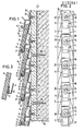
- Fig. 1 eine Seitenansicht in schnittbildlicher Darstellung einer Wandverkleidung;
- Fig. 2 in Draufsicht die Anordnung der Trägerhaken auf den Trägerprofilleisten des Ausführungsbeispiels in der Fig. 1 und
- Fig. 3 in Teilansicht ein weiteres Ausführungsbeispiel für die rückseitige Plattenhalterung.
- Bei dem in den Figuren 1 und 2 dargestellten Ausführungsbeispiel weist die Unterkonstruktion der Verkleidung an einer Hauswand 15 befestigte vertikale Holzleisten 18 auf. Diese Holzleisten sind mit Hilfe von Schrauben 19 an der Hauswand 15 befestigt. Auf jeder Holzleiste 18 ist ebenfalls in senkrechter Anordnung eine Trägerprofilleiste 1 befestigt. Die Unterkonstruktion weist mehrere derartige parallel verlaufende, senkrecht angeordnete Trägerprofilleisten 1 auf. Die Trägerprofilleisten besitzen gegenüber der Vertikalen schräg verlaufende Leistenabschnitte 3, zwischen denen jeweils etwa senkrecht verlaufende Befestigungsabschnitte 2 vorgesehen sind.
- An den Trägerprofilleisten 1 sind Trägerhaken 4, z. B. mittels Schrauben 14, die in die darunterliegende Holzleiste 18 eingeschraubt sind, befestigt. Jeder Trägerhaken 4 besitzt einen Hakenabschnitt 5 mit einer ebenen Rückfläche, die der nach außen gerichteten ebenen Fläche des schräg verlaufenden Leistenabschnitts 3 gegenüberliegt und zu dieser parallel verläuft. Der Abstand zwischen der Rückfläche am hakenförmigen Abschnitt 5 des Trägerhakens 4 und der nach außen gerichteten Fläche des schräg verlaufenden Leistenabschnitts 3 entspricht etwa der Dicke einer Verkleidungsplatte 6.
- Im Bereich der Befestigungsabschnitte 2 der Trägerprofilleiste 1 ist ein Langloch 16 vorgesehen, durch das die Befestigungsschraube 14 zur Befestigung des Trägerhakens 4 und der Trägerprofilleiste 1 an der Holzleiste 18 hindurchgeschraubt ist. Auf diese Weise läßt sich der Trägerhaken 4 gegenüber der Unterkonstruktion 10 höhenverstellbar an dieser befestigen. Das Langloch kann auch in einer Befestigungslasche 13 des Trägerhakens 4 vorgesehen sein.
- Zwischen dem hakenförmigen Abschnitt 5 und der Befestigungslasche 13 besitzt der Trägerhaken 4 eine Kröpfung 8. Durch diese Kröpfung 8 wird erzielt, daß die Rückfläche des hakenförmigen Abschnitts 5 den gewünschten Abstand von der nach außen gerichteten Fläche des schräg verlaufenden Leistenabschnitts 3 aufweist. Dieser Abstand entspricht der Dicke der Verkleidungsplatte.
- Beim dargestellten Ausführungsbeispiel der Fig. l greift der Trägerhaken 4 mit einem nach oben gerichteten Eingriffsteil bzw. Eingriffsschenkel 17 in eine an der Unterkante der Verkleidungsplatte 6, beispielsweise durch Fräsen, eingebrachte Eingriffsnut 11 ein. Die Verkleidungsplatte 6 sitzt dabei, von unten her abgestützt, auf dem waagrecht verlaufenden Teil des hakenförmigen Abschnitts 5 auf und ist gegen Herausfallen aus der Verkleidung gesichert durch den Eingriff des Eingriffsschenkels 17 in die Eingriffsnut 11.
- Am oberen Randbereich der Verkleidungsplatte 5 liegen deren beide Seitenflächen an der Rückfläche des hakenförmigen Abschnitts 5 und an der nach außen gerichteten Fläche des schräg verlaufenden Leistenabschnittes 3 auf. Es wird dadurch eine überlappende Anordnung der Verkleidungsplatten in der Verkleidung erzielt. Ferner wird eine einwandfreie Halterung der Verkleidungsplatten erreicht.
- Das Entfernen einer einzelnen Verkleidungsplatte 6 aus der Verkleidung läßt sich einfach dadurch ausführen, daß die Verkleidungsplatte 6 nach oben geschoben wird, weshalb der Abstand zwischen der Oberkante 7 der Verkleidungsplatte und der Kröpfung 8 am darüberliegenden Trägerhaken vorhanden ist. Dieser Abstand ist so bemessen, daß die Verkleidungsplatte 6 über den Eingriffsschenkel 17 angehoben werden kann, so daß die Eingriffsnut 11 außer Eingriff mit dem Eingriffsschenkel 17 kommt. Die Verkleidungsplatte 6 kann dann durch Auskippen an der Unterseite aus der Verkleidung entnommen werden. Beim Wiedereinbau einer neuen Verkleidungsplatte wird diese zwischen die Rückfläche des hakenförmigen Abschnitts 5 des Trägerhakens 4 und die nach außen gerichtete Fläche des schräg verlaufenden Leistenabschnitts 3 nach oben geschoben und dann nach unten gezogen, so daß der Eingriffsschenkel 17 wieder in die Eingriffsnut 11 an der Unterkante der Verkleidungsplatte 6 eingreift.
- Die Erstmontage der Verkleidungsplatten erfolgt so, daß zuerst die unterste Verkleidungsplatte eingesetzt wird und die oberste Verkleidungsplatte zuletzt. Beim Auswechseln mehrerer Verkleidungsplatten erfolgt der Ausbau der obersten Verkleidungsplatte zuerst und der Einbau der obersten Verkleidungsplatte zuletzt.
- Beim Ausführungsbeispiel der Fig. 3 befindet sich an der Rückseite der Verkleidungsplatte 6 ein Einhängeteil 12, beispielsweise in Form eines Profilblechs. In dieses wird der nach oben ragende Eingriffsschenkel 17 des hakenförmigen Abschnitts 12 am Trägerhaken 4 eingeschoben, bzw. die Verkleidungsplatte wird mit dem Einhängeteil auf den Eingriffsschenkel 17 aufgeschoben. Die Ausbildung des Trägerhakens und der Trägerprofilleiste ist wie beim Ausführungsbeispiel der Figuren 1 und 2.
- Die Verkleidungsplatten 6 können die in der Fig. l gezeigte abgestufte Ausbildung an der Unterkante aufweisen, um eine einwandfrei verdeckte Anordnung der Trägerhaken 4 zu erzielen. Es ist jedoch auch möglich, die Unterkante eben auszubilden.
- Ferner können die Verkleidungsplatten 6 noch durch Sicherungsschrauben 21 an den Trägerhaken 4 gesichert sein.
- Im Befestigungsabschnitt 2 der Trägerprofilleisten 1 ist eine waagrechte Riffelung 20 vorgesehen. Diese dient nicht nur zur einwandfreien rutschfesten Befestigung der Trägerhaken 4, sondern auch als Erleichterung beim Befestigen der Trägerhaken 4 an den Trägerprofilleisten 1. Beispielsweise kann zur Erleichterung der Montage an dem Befestigungshaken 4 eine entsprechende Markierung in Form eines Vorsprungs oder dgl. vorgesehen sein, die an oder in einer entsprechenden Riffelung angeordnet wird. Auf diese Weise läßt sich leicht die gewünschte Höheneinstellung der jeweiligen Trägerhaken 4 erreichen.
- Die Montage der Trägerprofilleisten 1 kann in der Weise erfolgen, daß die Höheneinstellung der schräg verlaufenden Leistenabschnitte 3 so erfolgt, daß jeweils einer dieser Leistenabschnitte auf den Trägerprofilleisten mit horizontal verlaufenden Hauselementen, z. B. Fensterstürzen, entsprechend ausgerichtet ist. Jede Leiste wird zunächst mit beispielsweise einer Schraube fixiert. Anschließend erfolgt dann die Montage der Traghaken an den Trägerprofilleisten, wobei unter Verwendung von Befestigungsschrauben sowohl die Traghaken an den Trägerprofilleisten als auch die endgültige Befestigung der Trägerprofilleisten an der Unterkonstruktion gleichzeitig erfolgen kann.
- Durch die vorstehend erwähnte Abstufung an der Unterkante der Verkleidungsplatte 6 wird ein Nässeschutz für die Trägerhaken 4 erzielt.
Claims (9)
daß die Trägerhaken (4) höhenverstellbar an den Trägerprofilleisten (1) befestigt sind.
daß die Trägerprofilleiste (1) im Bereich ihrer Befestigungsabschnitte (2) oder die Trägerhaken (4) im Bereich der Befestigungslasche (13) ein Langloch (16) aufweist bzw. aufweisen, durch das ein Befestigungsmittel (14) hindurchragt.
daß der schräg verlaufende Leistenabschnitt (3) der Trägerprofilleiste (1) gegenüber der Vertikalen um einen o Winkel von 10 bis 20 geneigt ist.
daß der Abstand zwischen der Oberkante (7) der Verkleidungsplatte (6) und der Kröpfung (8) des Trägerhakens (4) größer bemessen ist als die nach oben gerichtete Länge des Eingriffsteils (17) am hakenförmigen Abschnitt (5) des Trägerhakens (4).
daß die Verkleidungsplatte (6) zwischen die Rückfläche des hakenförmigen Abschnitts (5) des Trägerhakens (4) und die nach außen gerichtete Fläche des schräg verlaufenden Leistenabschnitts (3) der Trägerprofilleiste (1) geklemmt ist.
daß die Befestigungsabschnitte (2) der Trägerprofilleisten (1) eine waagrechte Riffelung (20) aufweisen.
Priority Applications (1)
| Application Number | Priority Date | Filing Date | Title |
|---|---|---|---|
| AT84107453T ATE31769T1 (de) | 1983-07-04 | 1984-06-27 | Wandverkleidung. |
Applications Claiming Priority (2)
| Application Number | Priority Date | Filing Date | Title |
|---|---|---|---|
| DE3324060A DE3324060C2 (de) | 1983-07-04 | 1983-07-04 | Wandverkleidung |
| DE3324060 | 1983-07-04 |
Publications (3)
| Publication Number | Publication Date |
|---|---|
| EP0130561A2 true EP0130561A2 (de) | 1985-01-09 |
| EP0130561A3 EP0130561A3 (en) | 1986-05-21 |
| EP0130561B1 EP0130561B1 (de) | 1988-01-07 |
Family
ID=6203102
Family Applications (1)
| Application Number | Title | Priority Date | Filing Date |
|---|---|---|---|
| EP84107453A Expired EP0130561B1 (de) | 1983-07-04 | 1984-06-27 | Wandverkleidung |
Country Status (3)
| Country | Link |
|---|---|
| EP (1) | EP0130561B1 (de) |
| AT (1) | ATE31769T1 (de) |
| DE (1) | DE3324060C2 (de) |
Cited By (3)
| Publication number | Priority date | Publication date | Assignee | Title |
|---|---|---|---|---|
| WO1997023696A1 (en) * | 1995-12-22 | 1997-07-03 | James Hardie Research Pty. Limited | A cladding board mounting system |
| EP0778195A3 (de) * | 1995-12-04 | 1997-07-16 | Chugoku Marine Paints | |
| EP1443160A1 (de) * | 2003-02-03 | 2004-08-04 | Rockwool International A/S | Fixierungsverfahren |
Families Citing this family (3)
| Publication number | Priority date | Publication date | Assignee | Title |
|---|---|---|---|---|
| DE19718716C2 (de) * | 1997-05-02 | 2002-08-01 | Max Gerhaher | Vorgehängte Fassadenkonstruktion |
| WO2019081626A1 (en) * | 2017-10-25 | 2019-05-02 | Komproment Holding Af 2007 Aps | MOUNTING SYSTEM FOR FACADE AND / OR ROOF ELEMENTS |
| DE202019001306U1 (de) | 2019-03-12 | 2019-04-15 | Systea Pohl Gmbh | Wandverkleidung |
Family Cites Families (10)
| Publication number | Priority date | Publication date | Assignee | Title |
|---|---|---|---|---|
| US3029560A (en) * | 1954-12-06 | 1962-04-17 | John B Benson | Building clip |
| US3174192A (en) * | 1961-09-13 | 1965-03-23 | Bruce G Heebink | Siding attachment to buildings |
| US3261136A (en) * | 1963-10-10 | 1966-07-19 | Weyerhaeuser Co | Fastening means for supporting siding panels |
| US3237360A (en) * | 1963-10-16 | 1966-03-01 | Thomas W Mills | Fastening means for overlapping boards |
| US3347009A (en) * | 1965-04-16 | 1967-10-17 | Olin Mathieson | Selectively removable panel assembly |
| SE321068B (de) * | 1968-12-09 | 1970-02-23 | Bostadsforskning Ab | |
| FR2291327A1 (fr) * | 1974-11-15 | 1976-06-11 | Roclaine | Procede pour la pose d'un bardage ou d'une couverture ou toiture sur une surface exterieure d'un batiment |
| DE2843457C2 (de) * | 1978-10-05 | 1983-03-03 | Manfred 7290 Freudenstadt Gehring | Wandbekleidung |
| DE3018398A1 (de) * | 1980-05-14 | 1981-11-19 | Profil-Vertrieb Gmbh, 7560 Gaggenau | Fassadenbekleidung |
| DE3132551A1 (de) * | 1981-08-18 | 1983-03-10 | ASZ Schneide-GmbH, 3012 Langenhagen | "vorrichtung zum schutz von an einer aussenwand zu befestigenden schienen" |
-
1983
- 1983-07-04 DE DE3324060A patent/DE3324060C2/de not_active Expired
-
1984
- 1984-06-27 AT AT84107453T patent/ATE31769T1/de not_active IP Right Cessation
- 1984-06-27 EP EP84107453A patent/EP0130561B1/de not_active Expired
Cited By (6)
| Publication number | Priority date | Publication date | Assignee | Title |
|---|---|---|---|---|
| EP0778195A3 (de) * | 1995-12-04 | 1997-07-16 | Chugoku Marine Paints | |
| US5885029A (en) * | 1995-12-04 | 1999-03-23 | Chugoku Paints Ltd. | Antifouling wall structure, method of constructing antifouling wall and antifouling wall panel transporter therefor |
| US6161989A (en) * | 1995-12-04 | 2000-12-19 | Chugoku Paints Ltd | Antifouling wall structure for use in pipe and method of constructing the antifouling wall therefor |
| WO1997023696A1 (en) * | 1995-12-22 | 1997-07-03 | James Hardie Research Pty. Limited | A cladding board mounting system |
| EP1443160A1 (de) * | 2003-02-03 | 2004-08-04 | Rockwool International A/S | Fixierungsverfahren |
| WO2004070133A1 (en) * | 2003-02-03 | 2004-08-19 | Rockwool International A/S | Fixing method |
Also Published As
| Publication number | Publication date |
|---|---|
| EP0130561B1 (de) | 1988-01-07 |
| EP0130561A3 (en) | 1986-05-21 |
| ATE31769T1 (de) | 1988-01-15 |
| DE3324060C2 (de) | 1985-04-25 |
| DE3324060A1 (de) | 1985-01-24 |
Similar Documents
| Publication | Publication Date | Title |
|---|---|---|
| DE69326847T2 (de) | Tragärmezusammensetzung für regale | |
| DE69016091T2 (de) | Wandvertäfelungssystem. | |
| DE69125572T2 (de) | Tragschiene für eine gläserne Tür oder Trennwand | |
| EP3563738B1 (de) | Duschablage | |
| DE3932176C2 (de) | Wandbekleidungselement, insbesondere Fassadenelement | |
| DE2334671A1 (de) | Spindeltreppe | |
| EP0130561B1 (de) | Wandverkleidung | |
| EP0606508A1 (de) | Verfahren und Einrichtung für den Schachttüreinbau bei Aufzügen | |
| EP0855477A2 (de) | Deckenaufbau | |
| DE69431958T2 (de) | Vorrichtung für eine paneelwand die aus paneelelementen gebildet ist | |
| EP0520132B1 (de) | Verkleidung für Gebäudefassaden oder dergl. | |
| DE3923800A1 (de) | Anordnung zur befestigung keramischer platten als wandverkleidung auf einer an einer wand angeordneten unterkonstruktion | |
| DE20200530U1 (de) | Unterkonstruktion für eine Wandbekleidung von Bauwerken mit Wandbekleidungsplatten aus einem massiven Werkstoff | |
| DE1958736A1 (de) | Anordnung zum Halten einer Regalplatte | |
| DE4026688A1 (de) | Fassadenverkleidung | |
| EP0271075B1 (de) | Anschlussprofil für Wand- und Deckenpaneele | |
| DE3332623A1 (de) | Fassadenverkleidung | |
| DE2606726C2 (de) | Nichttragende Wandkonstruktion | |
| DE8319266U1 (de) | Fassadenverkleidung | |
| DE69300094T2 (de) | Büromöbel zum schnellen Montieren und Demontieren. | |
| DE60106371T2 (de) | Lüftungsgitter zur Verwendung mit erhöhten Fussböden | |
| DE2748980C3 (de) | Keramische Heizkörperverkleidung | |
| DE29901043U1 (de) | Deckenplatte einer Unterdecke | |
| DE3702534A1 (de) | Befestigungsvorrichtung fuer fassadenplatten | |
| DE2643696C2 (de) | Montagehilfe für Deckeneinbauleuchten |
Legal Events
| Date | Code | Title | Description |
|---|---|---|---|
| PUAI | Public reference made under article 153(3) epc to a published international application that has entered the european phase |
Free format text: ORIGINAL CODE: 0009012 |
|
| AK | Designated contracting states |
Designated state(s): AT BE CH FR GB LI NL SE |
|
| PUAL | Search report despatched |
Free format text: ORIGINAL CODE: 0009013 |
|
| AK | Designated contracting states |
Kind code of ref document: A3 Designated state(s): AT BE CH FR GB LI NL SE |
|
| 17P | Request for examination filed |
Effective date: 19860729 |
|
| 17Q | First examination report despatched |
Effective date: 19870616 |
|
| GRAA | (expected) grant |
Free format text: ORIGINAL CODE: 0009210 |
|
| AK | Designated contracting states |
Kind code of ref document: B1 Designated state(s): AT BE CH FR GB LI NL SE |
|
| PG25 | Lapsed in a contracting state [announced via postgrant information from national office to epo] |
Ref country code: NL Effective date: 19880107 |
|
| REF | Corresponds to: |
Ref document number: 31769 Country of ref document: AT Date of ref document: 19880115 Kind code of ref document: T |
|
| PG25 | Lapsed in a contracting state [announced via postgrant information from national office to epo] |
Ref country code: SE Effective date: 19880131 |
|
| ET | Fr: translation filed | ||
| NLV1 | Nl: lapsed or annulled due to failure to fulfill the requirements of art. 29p and 29m of the patents act | ||
| GBV | Gb: ep patent (uk) treated as always having been void in accordance with gb section 77(7)/1977 [no translation filed] | ||
| PLBE | No opposition filed within time limit |
Free format text: ORIGINAL CODE: 0009261 |
|
| STAA | Information on the status of an ep patent application or granted ep patent |
Free format text: STATUS: NO OPPOSITION FILED WITHIN TIME LIMIT |
|
| PG25 | Lapsed in a contracting state [announced via postgrant information from national office to epo] |
Ref country code: GB Free format text: LAPSE BECAUSE OF NON-PAYMENT OF DUE FEES Effective date: 19881123 |
|
| 26N | No opposition filed | ||
| PGFP | Annual fee paid to national office [announced via postgrant information from national office to epo] |
Ref country code: FR Payment date: 19920630 Year of fee payment: 9 Ref country code: AT Payment date: 19920630 Year of fee payment: 9 |
|
| PGFP | Annual fee paid to national office [announced via postgrant information from national office to epo] |
Ref country code: BE Payment date: 19920710 Year of fee payment: 9 |
|
| PGFP | Annual fee paid to national office [announced via postgrant information from national office to epo] |
Ref country code: CH Payment date: 19921029 Year of fee payment: 9 |
|
| PG25 | Lapsed in a contracting state [announced via postgrant information from national office to epo] |
Ref country code: AT Effective date: 19930627 |
|
| PG25 | Lapsed in a contracting state [announced via postgrant information from national office to epo] |
Ref country code: LI Effective date: 19930630 Ref country code: CH Effective date: 19930630 Ref country code: BE Effective date: 19930630 |
|
| BERE | Be: lapsed |
Owner name: KLINK WINFRED Effective date: 19930630 |
|
| PG25 | Lapsed in a contracting state [announced via postgrant information from national office to epo] |
Ref country code: FR Effective date: 19940228 |
|
| REG | Reference to a national code |
Ref country code: CH Ref legal event code: PL |
|
| REG | Reference to a national code |
Ref country code: FR Ref legal event code: ST |