EP0122430B1 - Appareil de traitement d'une image - Google Patents
Appareil de traitement d'une image Download PDFInfo
- Publication number
- EP0122430B1 EP0122430B1 EP84102447A EP84102447A EP0122430B1 EP 0122430 B1 EP0122430 B1 EP 0122430B1 EP 84102447 A EP84102447 A EP 84102447A EP 84102447 A EP84102447 A EP 84102447A EP 0122430 B1 EP0122430 B1 EP 0122430B1
- Authority
- EP
- European Patent Office
- Prior art keywords
- image
- character
- image signal
- signal
- data
- Prior art date
- Legal status (The legal status is an assumption and is not a legal conclusion. Google has not performed a legal analysis and makes no representation as to the accuracy of the status listed.)
- Expired - Lifetime
Links
Images


Classifications
-
- G—PHYSICS
- G01—MEASURING; TESTING
- G01D—MEASURING NOT SPECIALLY ADAPTED FOR A SPECIFIC VARIABLE; ARRANGEMENTS FOR MEASURING TWO OR MORE VARIABLES NOT COVERED IN A SINGLE OTHER SUBCLASS; TARIFF METERING APPARATUS; MEASURING OR TESTING NOT OTHERWISE PROVIDED FOR
- G01D15/00—Component parts of recorders for measuring arrangements not specially adapted for a specific variable
- G01D15/14—Optical recording elements; Recording elements using X-or nuclear radiation
-
- G—PHYSICS
- G06—COMPUTING; CALCULATING OR COUNTING
- G06K—GRAPHICAL DATA READING; PRESENTATION OF DATA; RECORD CARRIERS; HANDLING RECORD CARRIERS
- G06K15/00—Arrangements for producing a permanent visual presentation of the output data, e.g. computer output printers
- G06K15/02—Arrangements for producing a permanent visual presentation of the output data, e.g. computer output printers using printers
- G06K15/12—Arrangements for producing a permanent visual presentation of the output data, e.g. computer output printers using printers by photographic printing, e.g. by laser printers
- G06K15/1276—Arrangements for producing a permanent visual presentation of the output data, e.g. computer output printers using printers by photographic printing, e.g. by laser printers adding two or more images, e.g. texturing, shading, form overlay
-
- G—PHYSICS
- G06—COMPUTING; CALCULATING OR COUNTING
- G06K—GRAPHICAL DATA READING; PRESENTATION OF DATA; RECORD CARRIERS; HANDLING RECORD CARRIERS
- G06K15/00—Arrangements for producing a permanent visual presentation of the output data, e.g. computer output printers
- G06K15/02—Arrangements for producing a permanent visual presentation of the output data, e.g. computer output printers using printers
- G06K15/12—Arrangements for producing a permanent visual presentation of the output data, e.g. computer output printers using printers by photographic printing, e.g. by laser printers
- G06K15/128—Arrangements for producing a permanent visual presentation of the output data, e.g. computer output printers using printers by photographic printing, e.g. by laser printers generating or processing printable items, e.g. characters
-
- G—PHYSICS
- G06—COMPUTING; CALCULATING OR COUNTING
- G06K—GRAPHICAL DATA READING; PRESENTATION OF DATA; RECORD CARRIERS; HANDLING RECORD CARRIERS
- G06K15/00—Arrangements for producing a permanent visual presentation of the output data, e.g. computer output printers
- G06K15/02—Arrangements for producing a permanent visual presentation of the output data, e.g. computer output printers using printers
- G06K15/12—Arrangements for producing a permanent visual presentation of the output data, e.g. computer output printers using printers by photographic printing, e.g. by laser printers
- G06K15/129—Colour printing
-
- H—ELECTRICITY
- H04—ELECTRIC COMMUNICATION TECHNIQUE
- H04N—PICTORIAL COMMUNICATION, e.g. TELEVISION
- H04N1/00—Scanning, transmission or reproduction of documents or the like, e.g. facsimile transmission; Details thereof
- H04N1/387—Composing, repositioning or otherwise geometrically modifying originals
- H04N1/3871—Composing, repositioning or otherwise geometrically modifying originals the composed originals being of different kinds, e.g. low- and high-resolution originals
-
- H—ELECTRICITY
- H04—ELECTRIC COMMUNICATION TECHNIQUE
- H04N—PICTORIAL COMMUNICATION, e.g. TELEVISION
- H04N1/00—Scanning, transmission or reproduction of documents or the like, e.g. facsimile transmission; Details thereof
- H04N1/387—Composing, repositioning or otherwise geometrically modifying originals
- H04N1/3872—Repositioning or masking
- H04N1/3873—Repositioning or masking defined only by a limited number of coordinate points or parameters, e.g. corners, centre; for trimming
-
- H—ELECTRICITY
- H04—ELECTRIC COMMUNICATION TECHNIQUE
- H04N—PICTORIAL COMMUNICATION, e.g. TELEVISION
- H04N1/00—Scanning, transmission or reproduction of documents or the like, e.g. facsimile transmission; Details thereof
- H04N1/46—Colour picture communication systems
-
- G—PHYSICS
- G06—COMPUTING; CALCULATING OR COUNTING
- G06K—GRAPHICAL DATA READING; PRESENTATION OF DATA; RECORD CARRIERS; HANDLING RECORD CARRIERS
- G06K2215/00—Arrangements for producing a permanent visual presentation of the output data
- G06K2215/0002—Handling the output data
- G06K2215/0062—Handling the output data combining generic and host data, e.g. filling a raster
- G06K2215/0065—Page or partial page composition
-
- G—PHYSICS
- G06—COMPUTING; CALCULATING OR COUNTING
- G06K—GRAPHICAL DATA READING; PRESENTATION OF DATA; RECORD CARRIERS; HANDLING RECORD CARRIERS
- G06K2215/00—Arrangements for producing a permanent visual presentation of the output data
- G06K2215/0082—Architecture adapted for a particular function
- G06K2215/0094—Colour printing
-
- Y—GENERAL TAGGING OF NEW TECHNOLOGICAL DEVELOPMENTS; GENERAL TAGGING OF CROSS-SECTIONAL TECHNOLOGIES SPANNING OVER SEVERAL SECTIONS OF THE IPC; TECHNICAL SUBJECTS COVERED BY FORMER USPC CROSS-REFERENCE ART COLLECTIONS [XRACs] AND DIGESTS
- Y10—TECHNICAL SUBJECTS COVERED BY FORMER USPC
- Y10S—TECHNICAL SUBJECTS COVERED BY FORMER USPC CROSS-REFERENCE ART COLLECTIONS [XRACs] AND DIGESTS
- Y10S347/00—Incremental printing of symbolic information
- Y10S347/90—Data processing for electrostatic recording
Definitions
- the present invention relates to an image processing apparatus for processing image data such as half tone and line images (e.g., characters), or code data such as a compression code.
- image data such as half tone and line images (e.g., characters), or code data such as a compression code.
- Ink jet, thermal transfer and laser beam printers are conventionally known as image processing apparatuses for reproducing a half tone image from a dot image wherein a dither method or a density pattern method is used to reproduce the half tone image by dot modulation of a small region.
- the dither method is mainly used to reproduce the half tone image by a color laser beam printer.
- Image data supplied from a color video camera or an image file to the color printer of the type described above is temporarily stored in a buffer memory in the color printer and is read out therefrom.
- the color printer performs dither processing to print out a dot image obtained in accordance with the density of the transferred image.
- character data is mixed with the half tone image data. As a result, the edge sharpness of the character image is degraded by dither processing, resulting in inconvenience.
- the half tone image is, at first, copied by a known copying apparatus.
- the resultant copying sheet is then used as a printing sheet and is printed with the characters by a hard copy printer.
- this method is time-consuming and cumbersome.
- it is difficult to align the image with the characters, resulting in an impractical application.
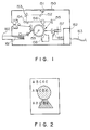
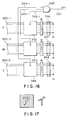
- a composite type electrophotographic copying apparatus is known, as shown in Fig. 1.
- This apparatus has a copying unit and a line printer (e.g., laser beam printer).
- a copy image of an original placed on an original table 150 is superimposed on a printer character output supplied from an external device (not shown) such as a host computer through a signal line 163.
- the composite image is then printed out on a copying sheet 161.
- the original table 150 is illuminated by an exposure lamp 151, and light reflected thereby is focused on the surface of a photosensitive drum 159 through mirrors 152 to 155 and a lens 156, so that a latent image corresponding to the original image is formed on a surface portion of the photosensitive drum 159.
- character data is supplied from the external device (not shown) to an interface control circuit 162 where it is converted to dot data.
- the dot data modulates a laser beam generated from a semiconductor laser 164.
- a polygonal mirror 157 serves to horizontally scan the laser beam.
- a latent character image is superimposed on a latent original image on the surface of the photosensitive drum 159.
- the normal electrophotographic process of consecutive development, transfer, and fixing is performed on a composite image consisting of both the half tone and character images.
- the half tone image is formed independently of the character image and is printed out. For example, when characters are superimposed on a substantially dark portion of the half tone image, the characters cannot be easily read, as shown in Fig. 2. In particular, the characters superimposed on the solid portion cannot be read entirely.
- US-A 4 316 199 describes an apparatus for printing graphic forms simultaneously with information data.
- a graphic forms master is read by a light sensitive transducer from where electrical signals, representing the graphic form are transmitted to a signal merging circuit which additionally receives information data signals.
- the signal merging circuit is connected to a single light source-optical system to selectively pass light to the photo-sensitive print drum in response to the electrical signals to provide an image thereon representing both the graphic form and the information data. Automatic lateral alignment of the graphic forms data and information data can be accomplished through cooperation of an alignment mark on the graphic forms master with a portion of the signals merging circuit.
- the invention provides an image processing apparatus capable of clearly discriminating between a line image portion, such as characters, and a superimposed half tone image portion, irrespective of the color of the background portion. Furthermore, the image processing apparatus according to the present invention is capable of combining a line image, such as characters, with a half tone image so as to reproduce a desired color image.
- the image processing apparatus is capable of reproducing a line image, such as characters, or a half tone image in a desired color, and/or combining a clear character image at a desired position of a reproduced image including a half tone image portion.
- the present invention furthermore provides a general-purpose image processing system which can be connected to any other equipment, and is capable of performing proper processing even if the input status (e.g., half tone dot data, character codes and compressed codes) of the image data differ from each other.
- a general-purpose image processing system which can be connected to any other equipment, and is capable of performing proper processing even if the input status (e.g., half tone dot data, character codes and compressed codes) of the image data differ from each other.
- the character image can be combined with the half tone image without degrading the edge sharpness of the character image.
- the character and half tone images can be moved to specified regions, respectively. Therefore, an effective, aesthetic design using the character and half tone images can be performed.
- a character image or the like can be entered using codes, so that the image processing apparatus of the present invention can be connected to any other equipment, thereby providing a general-purpose image processing apparatus.
- the character image can be reproduced in any color in accordance with the color of the half tone image as the background portion.
- the compression codes from, for example, a facsimile system can be received by merely adding input data discrimination commands. Therefore, various types of image entered from a variety of equipment can be combined.
- images suitable for subsequent clerical jobs can be obtained by changing the color of characters in units of specific data.
- the character image can be clearly reproduced irrespective of the color, hue, and density of the character image, the character image can be clearly discriminated from the solid image portion, unlike the conventional case wherein the character image cannot be clearly discriminated from the half tone image.
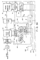
- Fig. 3 is a block diagram showing the overall configuration of an image processing apparatus according to a first embodiment of the present invention.
- This apparatus receives a character code string signal (Fig. 4) as character image data 101, a color discrimination signal 104 having R (red), G (green) and B (blue) components and vertical and horizontal synchronizing signals 106V and 106H, as shown in Fig. 5, which are supplied as color image data, and an image signal 105 supplied from external equipment such as a host computer.
- image trimming position designation signals 102, 103, 107 and 108 are also externally supplied to the color image recording apparatus.
- numerals on lines in Fig. 3 indicate the numbers of bits, respectively.
- Interface circuits 12 and 29 serve to store the character image data 101 and the half tone image data in a character code decoder 11 and an image buffer memory 28, respectively.
- Fig. 4 shows the character image data string signal.
- the data format of this signal includes character string data C10, C11, C12,... of the first line which follow a start discrimination code ITOP.
- a RET code is inserted after the end character of each line. Therefore, when the input device (i.e., color image recording apparatus) detects the RET code, carriage return is performed.
- Fig. 4 shows a first-line RET code R1 and a second-line RET code R2.
- An end code IEND of a character image is inserted at the end of the last line of the character image, thereby indicating the end of the character image data. When the color image recording apparatus receives this end code IEND, it discriminates the end of the character image data.
- the character image data 101 of one frame supplied in the manner described above is stored in a character code buffer 10.
- the special codes (ITOP, RET and IEND) are decoded by a character code decoder 11, so that a character image storage start/line return designation signal 109 and a storage end signal 110 are generated.
- a write address generator 19 sequentially generates address signals in response to the signal 109.
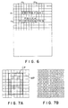
- Fig. 6 shows a character storage pattern. Characters A, B,..., a, b, c,... are represented by ASCII codes.
- the color image recording apparatus uses a laser beam system wherein an image to be reproduced is expressed as a dot image. Therefore, the character code string must be converted to the dot form.
- this embodiment employs a character generator 9.
- the character generator 9 generally has a character portion CP and a white portion WP, as shown in Fig. 7(a).
- character A is converted to dot data in accordance with the format shown in Fig. 7(a)
- data in the 9x9 pel (picture element) matrix are also converted to dot data, as shown in Fig. 7(b).
- the color image recording apparatus also receives an external region data signal 102 (row and column data of the character code image) which represents which region of one-character image is printed out.
- a printout start character and a printout end character are given by coordinates (m1,n1) and (m2,n2)
- the character data surrounded by the thick line are read out from the character code buffer 10.
- a read position designation circuit 17 and a read address generator 18 generate read address signals for the designated region.
- the designation signal 103 represents which print image region the designated character image is printed in.
- the write region for printout is given by a write start position pel number (scanning line number) (m1',n1') and a write end position pel number (m2',n2').
- An image memory write position designation circuit 15 and an image memory address generator 14 generate write addresses of an image memory 8.
- the character code image of a designated region which is read out from the character code buffer 10 in this manner is converted by the character generator 9 to dot data.
- This dot data is stored in a designated region of the image memory whose data is printed out.
- the data status is illustrated in Figs. 7(a) and 7(b).
- the color half tone image consists of the R-G-B color discrimination signal 104, the vertical and horizontal synchronizing signals 106V and 106H, and 8-bit density data (i.e., image signal) 105 for each pel of the image.
- 8-bit density data i.e., image signal
- 8-bit parallel density data is used.
- 8-bit serial density data may be used instead.
- the R, G and B components are stored in buffer memories 28-1, 28-2 and 28-3 respectively in accordance with the color discimination signal 104.
- the synchronizing signals 106V and 106H are supplied to a write address generator 32, so that necessary address signals are supplied from an address selector 30 to the image buffer memories 28-1, 28-2 and 28-3.
- image signal components of the respective colors are stored in the corresponding image buffer memories 28-1, 28-2 and 28-3.
- designation of the region to be printed out of the half tone image stored in the buffer memory is performed in response to the signal 107 simultaneously supplied from external equipment when the character code buffer 10 is subjected to read access.
- This region designation is performed by giving the printout start point, the pel number, and the scanning line number, so that address signals for the image memories 28-1, 28-2 and 28-3 are generated by an address generator 31.
- the color density data of the respective pels which are read out from the image buffer memories 28-1, 28-2 and 28-3 are gamma-transformed (density-converted) by a ⁇ correction circuit 27, so as to match the characteristics of the color image recording apparatus.
- these data are then subjected to masking by a masking processor 26 which is well-known in printing technique.
- These masked data are then subjected to UCR processing (undercolor removal) by means of a UCR processor 25.
- the UCR-processed data are then stored as dot data (binary data of logic "1" or "0") in a designated position of the image memory 21.
- dither processing is an electrical processing for comparing density data of each pel with its threshold value and generating recording dots to be produced.
- the dither circuit 24 may comprise a memory such as ROM, which may be directly accessed by using the density data as an address, thereby performing dither processing (dither conversion).
- processing by a method such as a density pattern method may be performed to determine the recording dots by comparing one pel with a plurality of threshold values. Processing by the density pattern method can also be referred to as dither processing.
- a yellow latent image, a magenta latent image, a cyan latent image and a black latent image are sequentially formed on the photosensitive drum 159 in the order named, and yellow, magneta, cyan and black toner images are superimposed on a transfer sheet to obtain a full-color image. Therefore, the image memory 21 has only one-image capacity. As each color image is formed on the photosensitive drum, the color processing described above is performed and at the same time the respective density data (Y, M, C and BK) are transferred into the image memory.
- these image data are stored as dot data in the image memories 8 and 21 and are assigned to identical addresses for identical pels.
- address designation of the image memories 8 and 21 is controlled by the image memory address generator 14. In other words, when the image data are in the image memories 8 and 21, respectively, the read addresses are generated, thereby sending out the character and half tone image dot data of the identical pel.
- the dot data read out from the image memories 8 and 21 are superposed by an OR gate 7, and a logic ORed data is supplied to a line buffer 6.
- the dot data read out from the line buffer 6 are supplied to the laser modulator 5.
- the laser modulator 5 produces a laser beam 4 in accordance with the dot data.
- the laser beam 4 modulated in response to the dot data irradiates a photosensitive drum 1 through the lens 2, so that a latent image is formed on a surface portion thereof.
- the print image formation process is the same as that in the conventional laser beam printer.
- Y, M, C and BK developing units (not shown) are selectively used.
- a signal 113 is a horizontal synchronizing signal (BD signal) generated from a sensor 40 when irradiated by the laser beam.
- the image data are read out from the image memories 8 and 21 in response to the signal 113.
- Fig. 3 shows a 4-bit signal 120 for designating the character image color.
- This signal may be supplied from external equipment such as a host computer or from a switch arranged in the color image recording apparatus.
- color designation signal bits C0 to C3 respectively correspond to Y, M, C and BK components.
- the character image output is controlled in response to a signal 112, thereby obtaining a character image having a desired color.
- the signal (C0, C1, C2, C4) (1, 1, 0, 0) is given.
- the character data is read out from the image memory 8, thereby reproducing a red character.
- the character image in the half tone image becomes sharp.
- the color designation signal (C0, C1, C2, C3) becomes (0, 0, 0, 1).
- the half tone image data is read out from the image memory 21, the data with a desired color may be controlled to be read out. In addition, either a single or a mixed color image can be obtained.
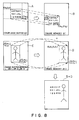
- Fig. 8 shows a case wherein the designated regions of the character image and the half tone image, respectively, are independently moved to specific positions, and the character and half tone images are combined.
- Input images A and C are moved to specific positions, and resultant images B and D are combined to obtain a composite image (B+D).
- Fig. 9 is a detailed diagram of the control circuit 16 shown in Fig. 3.
- the control circuit 16 mainly consists of two functional blocks represented by an I/O port 43 controlled by a CPU 40 such as a microcomputer and an address timing generator 44, respectively.
- a program ROM 41 of the CPU 40 stores a program.
- a data RAM 42 for the CPU 40 stores processed data.
- the I/O port 43 is connected to the following signal lines controlled by the CPU 40 and the program ROM 41.
- These signal lines consist of a signal line for sending a character buffer enable signal (to be referred to as a CBE hereinafter) 122 serving as a W/R enable signal of the character code buffer 10, a signal line for sending a character image memory enable signal (to be referred to as a CME hereinafter) 112 serving as a W/R enable signal of the character image memory 8, a signal line for sending a color image memory enable signal (to be referred to as a CLME hereinafter) 121 serving as a W/R enable signal of the half tone image memory 21, a signal line for sending a character buffer address select signal (to be referred to as a CBAS hereinafter) 123 serving as a W/R address switching signal of the character code buffer 10, a signal line for sending a character buffer R/W control signal (to be referred to as a CBRWC hereinafter) 124 serving as a W/R start signal of the character code buffer 10, a signal line for sending a character image memory R/W control signal (to be
- the input port of the I/O port 43 receives the color designation signal 120 for designating the color of the character image to be printed, the one-page storage end signal 110 as the IEND signal, and a print control signal (command) 127 for controlling the printing format (e.g., only the character image, a composite image of the character image and the half tone image, the print start and the print end).
- the address timing generator 44 generates a character code read timing signal (to be referred to as a CCRT hereinafter) 129 and a character dot write timing signal (to be referred to as a CDWT hereinafter) 130.
- the CCRT 129 serves as the count signal and the read timing signal for the address generation counter in the read address generator 18.
- the CDWT 130 serves as the count signal and the read/write timing signal of the address generation counter in the image memory address generator 14.
- the CCRT 129 and the CDWT 130 are supplied to the address generators 18 and 14 (not shown in Fig. 3), respectively.
- the CPU 40 in the control circuit 16 performs control operations such as image data transfer control (e.g., character code image and half tone color image data control), data storage control, and printout control in accordance with the data control commands supplied from the external equipment such as the host computer.
- the data control commands have character image or color image printout instructions and image data transfer start instructions from the external equipment, as shown in Fig. 10.
- the operation of the CPU 40 after the reception of the data control command will be described with reference to the flow chart of Fig. 12.
- the address generator 14 is used in the W/R access of the image memory 8.
- the memory is set in the memory read mode.
- the character image data are then read out by an image transfer clock (not shown) in synchronism with the image read sync signal 113.
- This readout image data is synchronized with the printer operation by the line buffer 6 and modulates the laser beam 4, thus contributing to image formation.
- the address generator 14 is set in the memory read mode in the same manner as in routine A.
- the character image memory 8 and the color half tone image memory 21 are enabled to reproduce a composite image (steps S211 to S213).
- the image can be printed out with a single color Y, M, C or BK or a combination of these colors.
- the color designation is performed in response to the color designation signal 120 supplied from external equipment such as a host computer.
- Routine A or C is performed at the time of predetermined color printout (development) by means of a color printer, thereby obtaining a print with a desired color.
- the image transfer start command will be described in detail.
- the external equipment such as a host computer must send any one of the character code transfer start command and the color image transfer start command to the color image recording device prior to transfer of the image data.
- routine D which is branched from step 203 is started.
- the address selector 20 selects the write address in response to the CBAS (character buffer address select) signal supplied from the CPU 40.
- the end of transfer is detected such that the IEND code inserted at the end of one page of the image is detected by the character code decoder which supplies the character code transfer end signal 110 to the CPU 40, thereby signalling the end of character code data transfer to the CPU 40.
- routine E branched from step S204 is started.
- the CLBE (image buffer memory enable) signal 134 is supplied to and enables the image buffer memory 28-1, 28-2, or 28-3 of a color designated by the color discrimination signal 104 of the transferred color image (steps S217 to S221), so that the predetermined color image data are stored in the corresponding image buffer memories.
- the CPU 40 In the write mode, the CPU 40 generates the address select signal (to be referred to as a CLBAS hereinafter) 132 to the corresponding image buffer memory which is to receive the write address.
- the CLBAS signal is also supplied to the address selector 30 (not shown in Fig. 3).
- the write address signal is supplied in synchronism with the vertical and horizontal synchronizing signals 106V and 106 H.
- the write address generator 30 supplies the storage end signal CIEND 133 (not shown in Fig. 3) to the CPU 40.
- the character codes are stored in the buffer memory 10, and the color half tone image data are respectively stored in the buffer memories 28-1, 28-2 and 28-3.
- the image data are subjected to predetermined processing, and the processed character and half tone data are transferred to the image memories 8 and 21, respectively.
- the read access of the character code buffer 10 and the write access of the image memory 8 will be described.
- the character code is read out from the character code buffer 10 in response to the address signal generated from the write address generator 18.
- the read position designation circuit 17 designates which region of one-page image is to be printed out. For example, in representation A of Fig. 8, the read position designation circuit 17 designates the upper left address (cx1,cy1) and the lower right address (cx2,cy2), so that the addresses are generated to read out data from the region surrounded by the rectangle. These address signals are supplied to the character code buffer 10. Similarly, in the color image, the upper left address (CLx1,CLy1) and the lower right address (CLx2,CLy2) are read out in the state of representation C of Fig.
- the readout image data are stored in the image memories 8 and 21, and the position data representing positions (of a copying sheet) at which the readout image is printed must be set in the write position designation circuit 15 or 23.
- the upper left address (CX1,CY1) and the lower right address (CX2,CY2) are set in the write position designation circuit 15, so that the readout character image is transferred to the position of presentation B of Fig. 8.
- addresses for designating the above-mentioned region are supplied by the signals 102, 103, 107 and 108 from the external equipment.
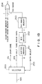
- Fig. 11 shows a data input section of the apparatus.
- the image data (character image data and color half tone image data) 100 transferred from the external equipment such as the host computer is supplied to the apparatus through a single cable.
- the character image data must be separated from the color half tone image data (i.e., character code processing system and color half tone image processing system).
- the CPU 40 sends a data select (DS) signal 140 to a data selector 46 in response to the character code transfer start command or the color image transfer command which is supplied from the external equipment such as the host computer prior to image data transfer, thereby performing switching of data processing systems.
- DS data select
- various types of data e.g., image data compression code string, any other code, or command string
- data discrimination signal data control command shown in Fig. 11
- switching circuit such as a data selector
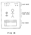
- the apparatus can receive the facsimile compressed code to combine a facsimile image with the character image and the color half tone image.
- the CPU 40 receives the FAX code discrimination command prior to transfer of the compression code.
- the CPU 40 then supplies a select signal (DS) 255 to a data selector 250 to select and receive a facsimile compressed code (e.g., MH code).
- the MH code is stored in a buffer memory 251 in the same manner as in storage of the character image data and the color half tone image data.
- the MH code When the MH code is stored, it is read out and is decoded by an MH decoder 252, thereby producing dot data.
- the dot data are then stored in a FAX image memory 253. In this case, a region is designated, and an image can be printed in the designated region in the same manner as previously described.
- the dot data are supplied to the printer through an OR gate 254. Therefore, the character image, the color half tone image and the facsimile image can be combined to obtain a composite image shown in Fig. 14.
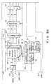
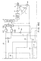
- Fig. 15 shows an image processing apparatus according to a third embodiment of the present invention.
- the same reference numerals used in Fig. 3 denote the same parts in Fig. 15, and a detailed description thereof will be omitted. Therefore, the parts of the apparatus of Fig. 15 which differ from those of Fig. 3 are mainly described.
- a dark tone extraction circuit 335 extracts a dark tone portion, and a dark tone memory 336 stores the dark tone portion.
- the dark tone extraction circuit 335 comprises comparators 342, 343 and 344, switches 346, 347 and 348, and so on.
- the switches 346, 347 and 348 serve to set the density components of Y (yellow), M (magenta) and C (cyan) to be discriminated as dark tones, respectively.
- the comparators 342, 343 and 344 compare the Y, M and C components of the input image density with preset values, respectively. When the input image density components exceed the preset values, respectively, data of logic "1" are produced for the corresponding pels.
- the comparators 342, 343 and 344 When all the input image densities of the Y, M and C components exceed the preset values, respectively, the comparators 342, 343 and 344 generate outputs 342-1, 343-1 and 344-1 of logic "1".
- This pel is regarded as the dark portion, so that data of "1" is stored in the dark tone memory 336 shown in Fig. 15.
- the data can be stored in the dark tone memory in response to an address signal 118 which is generated from an address generator 22 and which is used to access the dark tone memory in the same manner as in storage of data in the half tone image memory 21. Therefore, the dark tone memory 336 has the same capacity as that of the image memory 21.
- the color to be regarded to be a dark tone can change.
- the preset values of the switches 346 and 347 are increased to correspond to a high density, and the preset value of the switch 348 is set to be zero, the Y and M components have high densities, and the C component has a low density, so that the "red" portion is regarded to be a dark tone which can be used as the background color.
- a character image memory 8 and a half tone image memory 21 In order to read out the data from a character image memory 8 and a half tone image memory 21 and send the data to a laser modulator 5, these data are stored as dot data in the image memories 8 and 21 and the dark tone memory 336 and are assigned with the identical address for the identical pel.
- address access of the image memories 8 and 21 and the dark tone memory 336 is controlled by the image memory address generator 14. More particularly, when the image data are stored in the image memories 8 and 21, the read address is generated to read out dot data of the character image, thereby sending the half tone image and the dark tone portion which correspond to the identical pel.
- the dot data of the character image and the half tone image which are respectively read out from the image memories 8 and 21 act exclusively to each other.
- the background portion i.e., the data corresponding to the identical pel which is read out from the dark tone memory
- an output from an AND gate 337 is set to be logic "0"
- the background portion is set to be logic "0"
- an output from the AND gate 337 is set to be logic "1" so that a solid character is printed.
- the output from an AND gate 338 is set to be logic "0" irrespective of the type of the image data 116, so that the character region is not superposed on the half tone image.
- the resultant images are shown in Fig. 17.
- the hollow character is generated in a dark background or black solid portion.
- the solid character in black or any other color (to be described later) is generated when the background portion is white.
- a character image/half tone image selector 339 is controlled in accordance with a signal 114 from the control circuit 116 such that an input terminal A is coupled to an output terminal C when the character image is generated and that an input terminal B is coupled to the output terminal C when the half tone image is generated.
- An OR gate may be used in place of the selector 339. When the OR gate is used, the character image and the half tone image can be simultaneously produced, thereby decreasing the number of transfer operations.
- the yellow image is read out to operate a yellow developing unit (not shown) so as to form a yellow image on the photosensitive drum.
- the yellow image is transferred to a transfer sheet wound around the transfer drum, so that one-color transfer can be completed.
- magenta, cyan and black images are formed to obtain a four-color image.
- the selector 339 is switched to obtain a character image with a desired color.
- the signal 112 serves to control the color of the character image, as previously described.
- the character data is read out from the image memory 8 and is printed with a desired color in response to the signal 112.
- the image with a desired color may be controlled to be read out while the half tone image is read out from the image memory 21, thereby obtaining a single color or a mixed color image.
- Fig. 18 shows an image processing apparatus according to a fourth embodiment of the present invention.
- the same reference numerals used in Fig. 18 denote the same parts or functions in Fig. 3, and a detailed description thereof will be omitted. Only the parts of the apparatus (Fig. 18) which differ from those of the apparatus (Fig. 3) are mainly described.
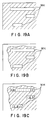
- a blank code generator 55 generates a blank code to form a blank or white portion of a half tone image which is printed with characters.
- the blank code generator 55 When the half tone image having blank portions is generated, the blank code generator 55 generates the blank code to a character generator 9 through a selector 56, so that blank portions are formed at positions where the character data read out from an image memory 8 is printed. Data of portions excluding the blank portions are set to be logic "1" in accordance with an input 215 to an OR gate 54.
- a half tone image output data selector 57 couples the input of an AND gate 67 and the output of the image memory 21.
- the final image data read out from the AND gate 67 is a half tone image or solid image having white or blank portions WH of Fig. 19(a) or Fig. 19(b).
- the selector 56 is operated such that a character code buffer 10 is coupled to the character generator 9.
- the character generator converts the character codes to the dot data which are then stored in the character image memory 8.
- the data selector 57 is connected such that the input to the AND gate 67 is set to be logic "1". Therefore, only the character dot data read out from the character image memory 8 are gated through the AND gate 67.
- an image shown in Fig. 19(c) is obtained as the final image wherein the predetermined characters are printed in the white or blank portions WH of the image shown in Fig. 19(b).
- the blank code generator 55 performs the following operation when the image shown in Fig. 19(a) is stored in the image memory 8.
- the character codes are sequentially supplied from the character code buffer 10 to the blank code generator 55 (signal lines for the character codes are not illustrated).
- the blank code generator 55 generates the blank codes to the portion excluding the blank portions.
- the blank code generator 55 supplies a signal (not shown) to the control circuit 16 so as to write data of "1" for the nonblank portion in response to an input 215.
- the control circuit 16 receives the signal from the blank code generator 55, the circuit 16 causes the address generator 14 to generate data of logic "1".
- the image shown in Fig. 19(a) is stored in the image memory 8. It should be noted that the character code buffer does not have control codes and stores only the character codes.
- the image produced by the data read out from the memories 8 and 21 can be temporarily displayed on the CRT display to check the position and color of characters to be superposed on the half tone image. Thereafter, printing can be performed.
- the yellow image, the magenta image, the cyan image, the black image, and the character image are sequentially formed on the photosensitive drum 1 and are superposed on the transfer sheet, thereby obtaining a full-color image.
- the color of the character image can be easily determined by selectively using the developers when the character image is printed out (developed).
- the character patterns are stored in the corresponding image memory.
- any other line image pattern may be stored in the character image memory.
- this embodiment employs the laser beam printer as an output device.
- the present invention is not limited to the laser beam printer but may be extended to an ink jet printer or a thermal transfer printer.
- a disk instead of the output device may be used to file the resultant composite image.
- the character data and the position designation signal are supplied from the external equipment in the above embodiment. However, these signals may be entered with data input keys arranged in the color image recording apparatus.
- the R, G and B color image data can be supplied from a CCD scanner or the like.
- the composite image can be stored in memories (Y, M, C and BK memories) in units of colors.
Landscapes
- Engineering & Computer Science (AREA)
- Physics & Mathematics (AREA)
- General Physics & Mathematics (AREA)
- Optics & Photonics (AREA)
- General Engineering & Computer Science (AREA)
- Theoretical Computer Science (AREA)
- Multimedia (AREA)
- Signal Processing (AREA)
- Facsimile Image Signal Circuits (AREA)
- Editing Of Facsimile Originals (AREA)
- Color Image Communication Systems (AREA)
Claims (12)
- Appareil de traitement d'images comportant(i) des moyens d'entrée de signal d'image destinés à introduire un signal d'image qui est stocké dans une première mémoire (28), des moyens destinés à traiter en demi-teintes ledit signal d'image pour produire un signal numérique d'image en demi-teintes qui est stocké dans une deuxième mémoire (21) ;(ii) des moyens d'entrée de signal de code de caractère destinés à introduire un signal de code de caractère qui est stocké dans une troisième mémoire (10), des moyens de conversion (9) destinés à convertir ledit signal de code de caractères en un signal numérique d'image de caractères qui est stocké dans une quatrième mémoire (8) ; et(iii) des moyens de formation d'une image commune (4-7) recevant le signal numérique stocké d'image en demi-teintes et le signal numérique stocké d'image de caractères, comprenant des moyens (14) de génération d'adresses pour les deux types de signaux d'images, et extrayant, pour chaque adresse, les signaux des deuxième et quatrième mémoires (21, 8) pour former une image graphique commune.
- Appareil de traitement d'image selon la revendication 1, dans lequel lesdits moyens de traitement des demi-teintes comprennent un moyen de correction du γ destiné à soumettre à une correction γ le signal d'image et traite en demi-teintes ledit signal d'image dont le γ est corrigé.
- Appareil selon la revendication 1 ou 2, comportant en outre des moyens (30, 31, 22) destinés à modifier les adresses dans la quatrième mémoire (8) en comparaison avec les adresses dans la première mémoire (10) et à modifier les adresses dans la deuxième mémoire (21) en comparaison avec les adresses dans la première mémoire (28).
- Appareil selon la revendication 1 ou 2, comportant en outre des moyens de désignation de couleur destinés à reproduire un caractère représenté par le signal d'image de caractères et/ou une image représentée par le signal d'image en demi-teintes en une couleur prédéterminée.
- Appareil selon la revendication 1, 2, 3 ou 4, dans lequel les moyens de conversion (9) convertissent le signal de code de caractères afin de produire des points d'image.
- Appareil selon l'une quelconque des revendications précédentes, comportant des moyens destinés à reproduire en une couleur prédéterminée une image représentée par le signal d'image introduit et/ou un caractère représenté par le signal de code de caractère introduit.
- Appareil selon l'une quelconque des revendications précédentes, comportant des moyens destinés à lire optiquement un document et à convertir les données lues en un signal d'image.
- Appareil selon l'une quelconque des revendications précédentes, comportant des moyens (337, 338, 339 sur la figure 15) destinés à combiner le signal d'image de caractères avec le signal d'image en demi-teintes ; et des moyens (335, 336, 340, 341) destinés à commander lesdits moyens de combinaison, lesdits moyens de commande (335, 336, 340, 341) modifiant un état de sortie du signal de caractère en fonction d'une teinte et/ou d'une densité du signal d'image.
- Appareil selon la revendication 8, dans lequel lesdits moyens de commande comportent des moyens de discrimination (335) destinés à discriminer si la teinte et/ou la densité du signal d'image dépassent ou non une valeur prédéterminée, lesdits moyens de discrimination étant agencés pour établir arbitrairement la valeur prédéterminée.
- Appareil selon l'une quelconque des revendications 1 à 7, comportant des moyens (67 sur la figure 18) destinés à combiner le signal d'image en demi-teintes avec le signal d'image de caractères ; et des moyens (16, 57) destinés à commander lesdits moyens de combinaison afin d'enregistrer la périphérie d'un caractère représenté par le signal d'image de caractère, d'une manière différente du caractère.
- Appareil selon la revendication 10, dans lequel lesdits moyens de commande (16, 57) sont agencés pour commander la sortie du signal d'image en demi-teintes dans une région prédéterminée qui comprend une image de caractère représentée par le signal d'image de caractère.
- Appareil selon l'une quelconque des revendications précédentes, comprenant des moyens (252, 253 sur la figure 13) destinés à décoder et à stocker des signaux de code de télécopie introduits et des moyens (254) destinés à les transmettre aux moyens (4-7) de formation d'une image commune.
Priority Applications (2)
| Application Number | Priority Date | Filing Date | Title |
|---|---|---|---|
| EP90120327A EP0422688B1 (fr) | 1983-03-08 | 1984-03-07 | Appareil pour le traitement d'images |
| EP90101031A EP0371005B2 (fr) | 1983-03-08 | 1984-03-07 | Appareil de traitement d'image |
Applications Claiming Priority (8)
| Application Number | Priority Date | Filing Date | Title |
|---|---|---|---|
| JP58036673A JPS59163944A (ja) | 1983-03-08 | 1983-03-08 | 画像処理装置 |
| JP36673/83 | 1983-03-08 | ||
| JP44990/83 | 1983-03-17 | ||
| JP58044991A JPH0642708B2 (ja) | 1983-03-17 | 1983-03-17 | 画像処理装置 |
| JP58044989A JPH0626434B2 (ja) | 1983-03-17 | 1983-03-17 | 画像処理装置 |
| JP44989/83 | 1983-03-17 | ||
| JP44991/83 | 1983-03-17 | ||
| JP58044990A JPH0754959B2 (ja) | 1983-03-17 | 1983-03-17 | 画像処理装置 |
Related Child Applications (3)
| Application Number | Title | Priority Date | Filing Date |
|---|---|---|---|
| EP90101031A Division EP0371005B2 (fr) | 1983-03-08 | 1984-03-07 | Appareil de traitement d'image |
| EP90101031.4 Division-Into | 1984-03-07 | ||
| EP90120327.3 Division-Into | 1984-03-07 |
Publications (3)
| Publication Number | Publication Date |
|---|---|
| EP0122430A2 EP0122430A2 (fr) | 1984-10-24 |
| EP0122430A3 EP0122430A3 (en) | 1985-06-19 |
| EP0122430B1 true EP0122430B1 (fr) | 1991-06-05 |
Family
ID=27460297
Family Applications (3)
| Application Number | Title | Priority Date | Filing Date |
|---|---|---|---|
| EP90120327A Expired - Lifetime EP0422688B1 (fr) | 1983-03-08 | 1984-03-07 | Appareil pour le traitement d'images |
| EP84102447A Expired - Lifetime EP0122430B1 (fr) | 1983-03-08 | 1984-03-07 | Appareil de traitement d'une image |
| EP90101031A Expired - Lifetime EP0371005B2 (fr) | 1983-03-08 | 1984-03-07 | Appareil de traitement d'image |
Family Applications Before (1)
| Application Number | Title | Priority Date | Filing Date |
|---|---|---|---|
| EP90120327A Expired - Lifetime EP0422688B1 (fr) | 1983-03-08 | 1984-03-07 | Appareil pour le traitement d'images |
Family Applications After (1)
| Application Number | Title | Priority Date | Filing Date |
|---|---|---|---|
| EP90101031A Expired - Lifetime EP0371005B2 (fr) | 1983-03-08 | 1984-03-07 | Appareil de traitement d'image |
Country Status (3)
| Country | Link |
|---|---|
| US (1) | US4682190A (fr) |
| EP (3) | EP0422688B1 (fr) |
| DE (3) | DE3486390T3 (fr) |
Families Citing this family (65)
| Publication number | Priority date | Publication date | Assignee | Title |
|---|---|---|---|---|
| EP0422688B1 (fr) * | 1983-03-08 | 1996-06-12 | Canon Kabushiki Kaisha | Appareil pour le traitement d'images |
| US4745560A (en) * | 1985-10-15 | 1988-05-17 | International Business Machines Corporation | Method of controlling a bit-image printer |
| EP0730370B1 (fr) * | 1985-11-18 | 2002-02-06 | Canon Kabushiki Kaisha | Dispositif de formation d'image |
| US4707709A (en) * | 1986-01-17 | 1987-11-17 | Eastman Kodak Company | Image recording apparatus in which exposure levels are a function of image contents |
| US5157773A (en) * | 1986-03-14 | 1992-10-20 | Canon Kabushiki Kaisha | Image data output apparatus |
| US5038298A (en) * | 1986-03-14 | 1991-08-06 | Canon Kabushiki Kaisha | Image output apparatus connectable to mutually different external data processing apparatus |
| DE3752300T2 (de) * | 1986-08-29 | 2000-04-13 | Canon Kk | Ein-/Ausgabegerät und Verfahren zur Verarbeitung von Bilddaten |
| JPS63268668A (ja) * | 1987-04-27 | 1988-11-07 | Nippon Kodatsuku Kk | サ−マルプリンタ |
| US5113492A (en) * | 1987-09-16 | 1992-05-12 | Canon Kabushiki Kaisha | Apparatus for processing character and image data |
| US5140675A (en) * | 1987-10-30 | 1992-08-18 | Canon Kabushiki Kaisha | Printer controller apparatus interfacing with external data sources |
| JPH021308A (ja) * | 1987-12-08 | 1990-01-05 | Rise Technol Inc | グレースケールアドーオン |
| JPH0759032B2 (ja) * | 1988-01-19 | 1995-06-21 | 富士ゼロックス株式会社 | 画像形成装置 |
| US5321470A (en) * | 1988-05-13 | 1994-06-14 | Canon Kabushiki Kaisha | Apparatus with anti-forgery provision |
| JP2925548B2 (ja) * | 1988-05-13 | 1999-07-28 | キヤノン株式会社 | 記録装置 |
| GB8811648D0 (en) * | 1988-05-17 | 1988-06-22 | Quantel Ltd | Electronic print dot generation |
| JPH01295854A (ja) * | 1988-05-25 | 1989-11-29 | Canon Inc | 印刷装置 |
| US4992958A (en) * | 1988-06-27 | 1991-02-12 | Hitachi, Ltd. | Method and apparatus for controlling printer |
| US5003496A (en) * | 1988-08-26 | 1991-03-26 | Eastman Kodak Company | Page memory control in a raster image processor |
| US5140674A (en) * | 1988-09-23 | 1992-08-18 | Hewlett-Packard Company | Text and color printing system |
| US5140349A (en) * | 1988-09-27 | 1992-08-18 | Canon Kabushiki Kaisha | Recording apparatus |
| JPH0251479U (fr) * | 1988-10-04 | 1990-04-11 | ||
| JPH02132963A (ja) * | 1988-11-14 | 1990-05-22 | Canon Inc | 画像処理装置 |
| EP0369719B1 (fr) * | 1988-11-14 | 1998-01-21 | Canon Kabushiki Kaisha | Appareil et méthode de traitement d'image |
| US5020004A (en) * | 1989-01-23 | 1991-05-28 | Canon Kabushiki Kaisha | Image output apparatus capable of outputting forms in special colors |
| US5128748A (en) * | 1989-02-15 | 1992-07-07 | Hitachi, Ltd. | Image processing system and apparatus for processing color documents |
| US4998214A (en) * | 1989-04-03 | 1991-03-05 | Unisys Corp. | Apparatus for line imaging |
| EP0397429B1 (fr) * | 1989-05-08 | 1997-03-26 | Canon Kabushiki Kaisha | Appareil et procédé de traitement d'images |
| JP3267289B2 (ja) * | 1989-05-10 | 2002-03-18 | キヤノン株式会社 | カラー画像処理方法 |
| US5631983A (en) * | 1989-05-10 | 1997-05-20 | Canon Kabushiki Kaisha | Image forming system for synthesizing color image data with binary image data which has been colored with a predetermined color during the synthesizing operation |
| JP2591167B2 (ja) * | 1989-07-11 | 1997-03-19 | ブラザー工業株式会社 | シリアルプリンタ |
| JPH0345076A (ja) * | 1989-07-12 | 1991-02-26 | Minolta Camera Co Ltd | 画像データの処理方式 |
| US5146554A (en) * | 1989-09-29 | 1992-09-08 | Eastman Kodak Company | Page memory control in a raster image processor employed for digital halftoning |
| US5136688A (en) * | 1989-09-29 | 1992-08-04 | Minolta Camera Kabushiki Kaisha | Print data processing apparatus for an image forming apparatus |
| US4991108A (en) * | 1989-10-06 | 1991-02-05 | Hamilton Cecil C | Data processor printer arrangement |
| EP0433056B1 (fr) * | 1989-12-15 | 1996-08-21 | Kabushiki Kaisha Toshiba | Système d'enregistrement d'images comprenant une image du visage et de l'information d'identification |
| DE69126467T2 (de) * | 1990-03-30 | 1998-01-15 | Canon Kk | Bildverarbeitungsverfahren und -gerät |
| US5126760A (en) * | 1990-04-25 | 1992-06-30 | Eastman Kodak Company | Direct digital halftone color proofing involving diode laser imaging |
| US5381248A (en) * | 1990-05-04 | 1995-01-10 | Canon Kabushiki Kaisha | Image processing apparatus |
| JP2560133B2 (ja) * | 1990-05-29 | 1996-12-04 | 大日本スクリーン製造株式会社 | 画像統合処理装置 |
| DE69126370T2 (de) * | 1990-06-25 | 1997-10-23 | Canon Kk | Bildverarbeitungsgerät und Bildverarbeitungsverfahren |
| IL98700A (en) * | 1990-07-13 | 1994-04-12 | Minnesota Mining & Mfg | A method and device for building a composite figure from several data types |
| US5426731A (en) * | 1990-11-09 | 1995-06-20 | Fuji Photo Film Co., Ltd. | Apparatus for processing signals representative of a computer graphics image and a real image |
| DE69125792T2 (de) * | 1990-11-16 | 1997-10-09 | Canon Kk | Bildschnittstellenanordnung |
| US5281803A (en) * | 1990-11-26 | 1994-01-25 | Canon Kabushiki Kaisha | Image sensor and information processing apparatus |
| WO1992012593A1 (fr) * | 1991-01-07 | 1992-07-23 | Eastman Kodak Company | Traitement du format distinct de texte et de donnees d'image picturale combines |
| JP3173040B2 (ja) * | 1991-05-10 | 2001-06-04 | ミノルタ株式会社 | 画像データ処理装置 |
| JP3176083B2 (ja) * | 1991-05-20 | 2001-06-11 | キヤノン株式会社 | 画像処理装置及びその方法 |
| US5566277A (en) * | 1991-06-17 | 1996-10-15 | Fuji Photo Film Co., Ltd. | Method and apparatus for recording an image |
| US6731399B2 (en) * | 1991-06-28 | 2004-05-04 | Canon Kabushiki Kaisha | System for processing a color image |
| US5933580A (en) | 1991-09-04 | 1999-08-03 | Canon Kabushiki Kaisha | Scanner printer server |
| KR100213472B1 (ko) * | 1991-10-30 | 1999-08-02 | 윤종용 | 화상데이타의 단순2치화 및 의사중간조 혼용처리방법 및 그 장치 |
| JP3230535B2 (ja) * | 1992-04-30 | 2001-11-19 | キヤノン株式会社 | 画像処理装置 |
| EP0590853B1 (fr) * | 1992-09-30 | 2000-11-08 | Hewlett-Packard Company | Méthode et système de sélection de palettes de couleurs pour imprimante à jet d'encre |
| CA2113960C (fr) | 1993-01-29 | 2001-07-31 | Kazuyoshi Takahashi | Appareil de transmission d'images, appareil de production d'images, appareil de commande connexe et systeme d'imagerie utilisant ces appareils |
| JPH07135575A (ja) * | 1993-11-12 | 1995-05-23 | Canon Inc | カラー画像情報出力装置 |
| EP0971309A3 (fr) | 1994-01-27 | 2002-10-30 | Hewlett-Packard Company, A Delaware Corporation | Optimisation automatique de copies sur papier |
| US5731823A (en) * | 1994-01-27 | 1998-03-24 | Hewlett-Packard Company | Automatic optimization of hardcopy output for enhanced appearance and throughput |
| JPH08204967A (ja) * | 1995-01-20 | 1996-08-09 | Nec Corp | データ符号化装置 |
| WO1997013354A1 (fr) * | 1995-10-05 | 1997-04-10 | Imation Corp. | Unite peripherique de sortie d'images medicales et son procede d'utilisation |
| JP3359234B2 (ja) * | 1996-07-31 | 2002-12-24 | キヤノン株式会社 | 画像処理装置及び方法 |
| US6249362B1 (en) | 1996-12-16 | 2001-06-19 | Canon Kabushiki Kaisha | Image read apparatus, information processing apparatus, and image read system constituted therewith |
| US6160632A (en) | 1997-11-06 | 2000-12-12 | Hewlett-Packard Company | Simplified method to print inherited pages in a page printer |
| JPH11252366A (ja) * | 1998-03-04 | 1999-09-17 | Seiko Epson Corp | プリンタ制御装置、プリンタ及びプリントシステム |
| US6244687B1 (en) | 1999-03-22 | 2001-06-12 | Hewlett-Packard Company | Mixing overprinting and underprinting of inks in an inkjet printer to speed up the dry time of black ink without undesirable hue shifts |
| US6132021A (en) * | 1999-06-10 | 2000-10-17 | Hewlett-Packard Company | Dynamic adjustment of under and over printing levels in a printer |
Citations (2)
| Publication number | Priority date | Publication date | Assignee | Title |
|---|---|---|---|---|
| US4316199A (en) * | 1980-01-07 | 1982-02-16 | Sperry Corporation | Graphic forms overlay apparatus |
| US4682190A (en) * | 1983-03-08 | 1987-07-21 | Canon Kabushiki Kaisha | Image processing apparatus for combining image and character data |
Family Cites Families (14)
| Publication number | Priority date | Publication date | Assignee | Title |
|---|---|---|---|---|
| US3593283A (en) * | 1966-09-19 | 1971-07-13 | Hitachi Ltd | Feature-extracting system for pattern-recognition apparatus and the like |
| DE2448505C3 (de) * | 1974-10-11 | 1978-03-09 | Robert Bosch Gmbh, 7000 Stuttgart | System zur selbsttätigen Korrektur der Farbbalance |
| US4210936A (en) * | 1977-12-27 | 1980-07-01 | Pitney Bowes Inc. | Method and apparatus for reproducing an original gray scale image |
| JPS5537092A (en) * | 1978-09-05 | 1980-03-14 | Ibm | Mode switch for setting threshold value |
| US4194221A (en) * | 1978-12-26 | 1980-03-18 | Xerox Corporation | Automatic multimode continuous halftone line copy reproduction |
| JPS55120265A (en) * | 1979-03-07 | 1980-09-16 | Ricoh Co Ltd | Picture forecasting restoring method |
| IL59886A (en) * | 1979-04-23 | 1983-06-15 | Dainippon Screen Mfg | Digital color control method and machine |
| JPS55146582A (en) * | 1979-04-27 | 1980-11-14 | Matsushita Electric Ind Co Ltd | Image recording method |
| US4249217A (en) * | 1979-05-29 | 1981-02-03 | International Business Machines Corporation | Separated sensor array abutment |
| JPS5629237A (en) * | 1979-08-16 | 1981-03-24 | Dainippon Screen Mfg Co Ltd | Image scanning and recording method |
| US4259694A (en) * | 1979-08-24 | 1981-03-31 | Xerox Corporation | Electronic rescreen technique for halftone pictures |
| US4403874A (en) * | 1980-03-25 | 1983-09-13 | Ramtek Corporation | Color printer and multi-ribbon cartridge therefor |
| US4394089A (en) * | 1981-09-23 | 1983-07-19 | Logetronics, Inc. | Color photoprinting with a scanning memory mask |
| JPS5811941A (ja) * | 1981-07-16 | 1983-01-22 | Dainippon Screen Mfg Co Ltd | 網目版画像記録装置における絵柄信号と文字信号の処理方法 |
-
1984
- 1984-03-07 EP EP90120327A patent/EP0422688B1/fr not_active Expired - Lifetime
- 1984-03-07 DE DE3486390T patent/DE3486390T3/de not_active Expired - Lifetime
- 1984-03-07 EP EP84102447A patent/EP0122430B1/fr not_active Expired - Lifetime
- 1984-03-07 EP EP90101031A patent/EP0371005B2/fr not_active Expired - Lifetime
- 1984-03-07 DE DE8484102447T patent/DE3484661D1/de not_active Expired - Lifetime
- 1984-03-07 DE DE3486434T patent/DE3486434T2/de not_active Expired - Lifetime
-
1986
- 1986-05-30 US US06/869,824 patent/US4682190A/en not_active Expired - Lifetime
Patent Citations (2)
| Publication number | Priority date | Publication date | Assignee | Title |
|---|---|---|---|---|
| US4316199A (en) * | 1980-01-07 | 1982-02-16 | Sperry Corporation | Graphic forms overlay apparatus |
| US4682190A (en) * | 1983-03-08 | 1987-07-21 | Canon Kabushiki Kaisha | Image processing apparatus for combining image and character data |
Also Published As
| Publication number | Publication date |
|---|---|
| DE3484661D1 (de) | 1991-07-11 |
| EP0422688A1 (fr) | 1991-04-17 |
| US4682190A (en) | 1987-07-21 |
| EP0122430A3 (en) | 1985-06-19 |
| EP0422688B1 (fr) | 1996-06-12 |
| DE3486390D1 (de) | 1995-07-13 |
| DE3486390T3 (de) | 1999-05-12 |
| EP0371005B2 (fr) | 1998-10-28 |
| EP0122430A2 (fr) | 1984-10-24 |
| EP0371005B1 (fr) | 1995-06-07 |
| EP0371005A1 (fr) | 1990-05-30 |
| DE3486434D1 (de) | 1996-07-18 |
| DE3486390T2 (de) | 1995-12-07 |
| DE3486434T2 (de) | 1996-12-19 |
Similar Documents
| Publication | Publication Date | Title |
|---|---|---|
| EP0122430B1 (fr) | Appareil de traitement d'une image | |
| US6977754B2 (en) | Image processing apparatus, an image processing method and computer program product for combining page description language image data and bitmap image data | |
| EP0733958B2 (fr) | Appareil de traitement d'images | |
| US5109274A (en) | Color image processing apparatus | |
| US20070091339A1 (en) | Image processing method, system and apparatus, and storage medium | |
| US7058196B2 (en) | Apparatus and method for processing image and computer-readable storage medium | |
| US5640253A (en) | Image processing apparatus | |
| US5159444A (en) | Apparatus for reading and reproducing a color image | |
| JPH0519862B2 (fr) | ||
| EP0723362B1 (fr) | Dispositif de formation d'image en couleur | |
| JP2684376B2 (ja) | カラー画像処理装置 | |
| US5555093A (en) | Image processing apparatus and method thereof | |
| JP2603210B2 (ja) | 画像処理装置 | |
| JPH0754959B2 (ja) | 画像処理装置 | |
| JP2750115B2 (ja) | 画像処理方法及び装置 | |
| JPH07112236B2 (ja) | 画像処理装置 | |
| JPH0642708B2 (ja) | 画像処理装置 | |
| JPH03247074A (ja) | 画像処理装置 | |
| JPH09156160A (ja) | 像形成方法 | |
| JPH03247163A (ja) | 画像処理装置 | |
| JPH02283169A (ja) | 画像処理装置 | |
| JPH0951425A (ja) | 画像処理装置及び方法 | |
| JP2509468B2 (ja) | 画像処理装置 | |
| JPH05286170A (ja) | 画像形成装置 | |
| JPH1188653A (ja) | 画像処理装置及び方法及び記憶媒体 |
Legal Events
| Date | Code | Title | Description |
|---|---|---|---|
| PUAI | Public reference made under article 153(3) epc to a published international application that has entered the european phase |
Free format text: ORIGINAL CODE: 0009012 |
|
| AK | Designated contracting states |
Designated state(s): DE FR GB |
|
| PUAL | Search report despatched |
Free format text: ORIGINAL CODE: 0009013 |
|
| AK | Designated contracting states |
Designated state(s): DE FR GB |
|
| 17P | Request for examination filed |
Effective date: 19850418 |
|
| 17Q | First examination report despatched |
Effective date: 19880125 |
|
| GRAA | (expected) grant |
Free format text: ORIGINAL CODE: 0009210 |
|
| AK | Designated contracting states |
Kind code of ref document: B1 Designated state(s): DE FR GB |
|
| XX | Miscellaneous (additional remarks) |
Free format text: TEILANMELDUNG 90101031.4 EINGEREICHT AM 07/03/84. |
|
| REF | Corresponds to: |
Ref document number: 3484661 Country of ref document: DE Date of ref document: 19910711 |
|
| ET | Fr: translation filed | ||
| PLBE | No opposition filed within time limit |
Free format text: ORIGINAL CODE: 0009261 |
|
| STAA | Information on the status of an ep patent application or granted ep patent |
Free format text: STATUS: NO OPPOSITION FILED WITHIN TIME LIMIT |
|
| 26N | No opposition filed | ||
| REG | Reference to a national code |
Ref country code: GB Ref legal event code: IF02 |
|
| PGFP | Annual fee paid to national office [announced via postgrant information from national office to epo] |
Ref country code: GB Payment date: 20030305 Year of fee payment: 20 |
|
| PGFP | Annual fee paid to national office [announced via postgrant information from national office to epo] |
Ref country code: FR Payment date: 20030310 Year of fee payment: 20 |
|
| PGFP | Annual fee paid to national office [announced via postgrant information from national office to epo] |
Ref country code: DE Payment date: 20030320 Year of fee payment: 20 |
|
| PG25 | Lapsed in a contracting state [announced via postgrant information from national office to epo] |
Ref country code: GB Free format text: LAPSE BECAUSE OF EXPIRATION OF PROTECTION Effective date: 20040306 |
|
| REG | Reference to a national code |
Ref country code: GB Ref legal event code: PE20 |