EP0038024B1 - Appareil pour appliquer de la teinture pour cheveux - Google Patents
Appareil pour appliquer de la teinture pour cheveux Download PDFInfo
- Publication number
- EP0038024B1 EP0038024B1 EP81102669A EP81102669A EP0038024B1 EP 0038024 B1 EP0038024 B1 EP 0038024B1 EP 81102669 A EP81102669 A EP 81102669A EP 81102669 A EP81102669 A EP 81102669A EP 0038024 B1 EP0038024 B1 EP 0038024B1
- Authority
- EP
- European Patent Office
- Prior art keywords
- storage container
- application part
- applicator according
- hair colour
- piston rod
- Prior art date
- Legal status (The legal status is an assumption and is not a legal conclusion. Google has not performed a legal analysis and makes no representation as to the accuracy of the status listed.)
- Expired - Lifetime
Links
- 239000000118 hair dye Substances 0.000 title abstract description 6
- 230000008878 coupling Effects 0.000 claims description 11
- 238000010168 coupling process Methods 0.000 claims description 11
- 238000005859 coupling reaction Methods 0.000 claims description 11
- 230000006835 compression Effects 0.000 claims description 4
- 238000007906 compression Methods 0.000 claims description 4
- 238000004140 cleaning Methods 0.000 claims description 3
- 229920002994 synthetic fiber Polymers 0.000 claims 1
- 230000037308 hair color Effects 0.000 description 18
- 239000007788 liquid Substances 0.000 description 4
- 238000000034 method Methods 0.000 description 3
- 239000003973 paint Substances 0.000 description 3
- 210000000078 claw Anatomy 0.000 description 2
- 238000004040 coloring Methods 0.000 description 1
- 210000001520 comb Anatomy 0.000 description 1
- 238000010276 construction Methods 0.000 description 1
- 238000011161 development Methods 0.000 description 1
- 230000018109 developmental process Effects 0.000 description 1
- 238000004043 dyeing Methods 0.000 description 1
- 230000005484 gravity Effects 0.000 description 1
- MHAJPDPJQMAIIY-UHFFFAOYSA-N hydrogen peroxide Substances OO MHAJPDPJQMAIIY-UHFFFAOYSA-N 0.000 description 1
- 238000004898 kneading Methods 0.000 description 1
- 239000000463 material Substances 0.000 description 1
- 239000000203 mixture Substances 0.000 description 1
- 239000002991 molded plastic Substances 0.000 description 1
- 239000007787 solid Substances 0.000 description 1
- XLYOFNOQVPJJNP-UHFFFAOYSA-N water Substances O XLYOFNOQVPJJNP-UHFFFAOYSA-N 0.000 description 1
Images

Classifications
-
- A—HUMAN NECESSITIES
- A45—HAND OR TRAVELLING ARTICLES
- A45D—HAIRDRESSING OR SHAVING EQUIPMENT; EQUIPMENT FOR COSMETICS OR COSMETIC TREATMENTS, e.g. FOR MANICURING OR PEDICURING
- A45D19/00—Devices for washing the hair or the scalp; Similar devices for colouring the hair
- A45D19/02—Hand-actuated implements, e.g. hand-actuated spray heads
- A45D19/026—Hand-actuated implements, e.g. hand-actuated spray heads having brush or comb applicators
Definitions
- the invention relates to a hair color applicator according to the preamble of claim 1.
- a hair dye applicator of the same type is known, for example, from US Pat. No. 2,299,296.
- Such a device is used, inter alia, for applying a hair color to a strand of hair by means of an application part which communicates with a passage opening for a color delivery and is optionally removable.
- the disadvantage is that an already mixed hair color must be introduced into the storage container, which means that a separate mixing container must be used.
- Another disadvantage is the fact that the tufts of bristles can be completely flooded with paint, which results in an unwanted dripping of the paint or too much paint on strands of hair.
- the invention has set itself the task of specifying a novel construction of a hair color application device, in particular for cream-like hair color, in which the filling, mixing and application process is to be facilitated by simple constructive measures, with a flawless, sufficient quantity of color - in particular for the hairline - should be achieved.
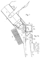
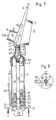
- the first embodiment shown in FIG. 1 has a storage container 1 designed as a handle part with an elastic, crushable and transparent wall 2.
- An application part 4 is screwed onto the container opening 3 of the storage container 1 and bears a projecting compartment tip 5, a comb part 6 with comb prongs 7 and a brush attachment 8.
- the compartment tip 5 forms an angle a of approximately 40 ° with the longitudinal axis of the storage container 1.
- the longitudinal axis of the comb teeth 7 forms an angle y of 75 ° with the longitudinal axis of the storage container 1.
- the longitudinal axis of the brush tufts 9 of the brush attachment 8 opposite the comb part forms an angle ⁇ of approximately 50 ° with the longitudinal axis of the storage container 1.
- the brush attachment 8 has, on the side facing the application part 4, a dovetail-shaped groove 10 which can be displaced on a dovetail-shaped spring 11 which is correspondingly formed on the application part 4 as a counterpart.
- the end of the dovetail-shaped spring 11 facing the storage container 1 carries one slot-shaped passage opening 13, which connects the interior 14 of the application part 4 with the interior of the storage container 1.
- the part of the brush attachment located above the passage opening 13 carries an elastic, slit-shaped rubber grommet 15 which, when the brush attachment 8 is removed, has been inserted from the dovetail-shaped groove 10 through a corresponding opening in the brush attachment 8.
- the slot-shaped rubber grommet 15 is surrounded by brush tufts 9 on both long sides and its outlet opening 15 b is surmounted by the latter.
- the application part 4 is unscrewed from the storage container 1 and the components of the hair color - hydrogen peroxide and the special hair color are filled in through the container opening 3.
- the quantity required can be read off on a scale attached to the outer wall of the container.
- the mixing position shown in FIG. 1a is obtained, in which the passage opening 13 is closed by the extension 10a.
- the components of the hair color are mixed with one another by kneading and shaking the wall 2.
- the brush attachment 8 is brought back into the order shown in FIG. 1 and the hair coloring process can thus be started.
- the user takes the hair color applicator in accordance with the working position shown in FIG.
- the slit-shaped rubber grommet 15 can take part in the brush movements at any time.
- the remaining hair color in the hair color applicator can be easily cleaned with warm water after removing the brush attachment 8 and after unscrewing the application part 4 from the storage container 1. Then the hair coloring process described above can be repeated as often as you like.
- the wall 2 of the storage container 1 made of material that is too stiff - generally injection-molded plastic - is used, it cannot be completely emptied when coloring the hair, as a result of which a certain residual amount must subsequently be rinsed out.
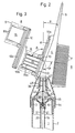
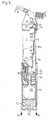
- the second embodiment shown in FIGS. 2 to 5 has the change or addition described below compared to the first embodiment.
- the application part 4 has slightly different geometric dimensions than that shown in FIG. 1.
- the compartment tip 5 forms an angle a of approximately 11 ° with the longitudinal axis of the storage container 1.
- the longitudinal axis of each comb prong 7 forms an angle y of approximately 82.5 ° with the longitudinal axis of the storage container 1.
- the longitudinal axis of each brush tuft 9 forms an angle a of approximately 70 ° with the longitudinal axis of the storage container 1.
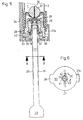
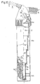
- the storage container 1 has a cylindrical, transparent but solid wall 2, in the interior of which a piston 16 is arranged to be axially displaceable. With this piston, a piston rod 17 is axially fixed, but rotatably connected, which projects beyond the rear end of the storage container 1, as can be seen more clearly from FIGS. 4 and 5.
- the piston rod 17 carries on each of its diametrically opposite longitudinal sides a rack 19 and 20 which is firmly connected to it and which are fitted with sawtooth-shaped teeth 21.
- Claw-shaped extensions 23 of a transport device 22 engage in the teeth 21 of the piston rod 17 and are connected in an elastically resilient manner to a ring 24.
- the ring 24 is pressed in the direction of the free end 29 of the piston rod 17 by the compression spring 25, which is supported on the inner wall 26 of the closure cap 27.
- an actuating element 31 which comprises the piston rod 17 and is movably mounted about a swivel joint 32.
- the free end 33 of the actuating member 31 is connected in an articulated manner to an actuating rod 28 mounted on the outer wall of the storage container 1 in a cover 34 so as to be longitudinally displaceable.
- the actuating rod 28 has an actuating extension 35 at its end facing the application part 4, as can be seen from FIG. 4.
- the closure cap 27 is detachably screwed to the end of the storage container 1 remote from the application part 4 and is secured in a known manner against inadvertent unscrewing by an axially displaceable safety button (27a). (Fig. 5).
- a ball 37 fixed to a thread 36 with the piston 16 is arranged in the interior of the storage container 1 in the area between the piston 16 and the application part 4. Mixing the hair color is made considerably easier by this ball 37, as can be seen more clearly from FIG. 2. So that this ball 37 when necessary disassembly, e.g. when cleaning, not lost, it is secured against loss with the thread 36.
- the application part 4, which can optionally be removed from the storage container 1 has a pin 39 projecting axially in the direction of the storage container 1, the length of which is dimensioned such that when the application part 4 is placed between the ball 37 and the wall of the application part 4, a through opening 40 for the person to be exited Hair color remains free (Fig. 2).
- the end of the storage container 1 facing away from the application part 4 is optionally firmly closed by a closure cap 27 which has the inner wall 26 and the outer wall 30 and has an axial opening 41 for the piston rod 17.
- the axial opening 41 in the outer wall 30 carries two diametrically inwardly projecting projections 42 and 43, which cooperate with the side flanks of the racks 19 and 20 on the piston rod 17 such that by rotating the piston rod 17 - also in the piston 16, the does not have to turn - the transport position is set by 90 ° when one side tooth flank stops on the assigned side of the two projections 42 and 43 and when the other side tooth flank stops on the opposite side of the two projections 42 and 43 the filling position is set . In the filling position, the piston rod 17 with the piston 16 attached to it can be moved axially freely.
- the intermediate piece 46 carrying the screw thread 4a can optionally be removed from the remaining application part 4 by means of an additional screw thread 45.
- the end of the intermediate piece 46 facing the remaining application part 4 carries a threaded connector 47 with a smaller inside diameter in relation to the inner diameter of the container opening 3 of the storage container 1, rod 39 interacting with the ball 37 being firmly connected to the remaining part of the application part 4 (Fig. 2).
- the emptied storage container 1 with the intermediate piece 46 with its threaded connector 47 can now be placed directly on a large pack with the component to be filled and by overpressure, for. B. by a pump, with returning pistons 16 optionally filled until the end position shown in FIG. 5 is reached. If the storage container 1 is held with the intermediate piece 46 pointing downward, the ball 37 seals against the inner wall of the intermediate piece 46 due to the force of gravity and only opens when there is excess pressure.
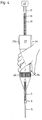
- a differently designed transport device 22 is used, in which the actuating member 31 has an actuating extension 35 projecting outwards, which in the rest position has an angle 8 of approximately 4 ° with the outer wall 2 of the storage container 1 .
- the arrangement is such that in the transport position when the actuating extension 35 is pressed against the outer wall 2 of the storage container 1, the piston rod 17 and the piston 16 connected therewith are transported in the direction of the application part 4.
- the actuation is essentially carried out by the ring finger and the smallest finger of the user.
- the piston rod 17 is designed telescopically, in which the individual tube parts 18 forming the telescopic piston rod 17 each have an external or internal thread 18a, which engages in pairs, the piston 16 being fixed against rotation arranged in the cylindrical wall 2 and the end of the driven tube part 18 which is remote from the piston 16 is preferably connected in a rotationally fixed manner to the drive shaft 49 of the direct current motor 50.
- a preferably cylindrical housing part 51 containing the DC motor 50 and a rechargeable battery 52 can optionally be uncoupled from the storage container 1 by means of a coupling device for cleaning purposes.
- the inner wall of the housing part 51 faces the storage container 1.
- the housing part 51 has on its cylindrical outer side an axially displaceable, concentrically arranged locking sleeve 57, which is shown in FIG. 11 in the locking state.
- the inside of this locking sleeve 57 has a wide circumferential annular recess 59 which, when axially displaced against the force of a spring (not shown), comes to rest behind the knob-like projections 54 in the direction of arrow 60, as a result of which it is attached the counter member of the coupling device formed on the storage container 1 can spring the projections 54 radially outward until they engage in the annular groove 55 (FIG. 9).
- the spring not shown, the locking sleeve is released pushed back into the locking position shown.
- the battery 52 is recharged via the two contact springs 56 from a power supply charger, which is preferably designed as a stand, in the unused idle times.
- a power supply charger which is preferably designed as a stand, in the unused idle times.
- an actuation extension (not shown) (similar to the actuation extension 35 in FIG. 4) is also formed, via which an electrical switch for switching the DC motor 50 on and off is actuated.
Landscapes
- Cleaning And Drying Hair (AREA)
- Brushes (AREA)
- Cosmetics (AREA)
Claims (21)
Priority Applications (1)
| Application Number | Priority Date | Filing Date | Title |
|---|---|---|---|
| AT81102669T ATE49341T1 (de) | 1980-04-10 | 1981-04-09 | Haarfarbeauftragegeraet. |
Applications Claiming Priority (2)
| Application Number | Priority Date | Filing Date | Title |
|---|---|---|---|
| DE3013769A DE3013769C2 (de) | 1980-04-10 | 1980-04-10 | Haarfarbeauftragegerät |
| DE3013769 | 1980-04-10 |
Publications (3)
| Publication Number | Publication Date |
|---|---|
| EP0038024A2 EP0038024A2 (fr) | 1981-10-21 |
| EP0038024A3 EP0038024A3 (en) | 1986-09-03 |
| EP0038024B1 true EP0038024B1 (fr) | 1990-01-10 |
Family
ID=6099655
Family Applications (1)
| Application Number | Title | Priority Date | Filing Date |
|---|---|---|---|
| EP81102669A Expired - Lifetime EP0038024B1 (fr) | 1980-04-10 | 1981-04-09 | Appareil pour appliquer de la teinture pour cheveux |
Country Status (5)
| Country | Link |
|---|---|
| US (1) | US4592376A (fr) |
| EP (1) | EP0038024B1 (fr) |
| JP (1) | JPS56151005A (fr) |
| AT (1) | ATE49341T1 (fr) |
| DE (2) | DE3013769C2 (fr) |
Cited By (2)
| Publication number | Priority date | Publication date | Assignee | Title |
|---|---|---|---|---|
| US6145513A (en) * | 1999-02-26 | 2000-11-14 | New Basics, Inc. | Hair dye applicator |
| USD519674S1 (en) | 2003-10-17 | 2006-04-25 | New Basics, Inc. | Hair fluid applicator |
Families Citing this family (37)
| Publication number | Priority date | Publication date | Assignee | Title |
|---|---|---|---|---|
| US4605026A (en) * | 1983-04-06 | 1986-08-12 | Nolin Rosemary D | Comb for dispensing treatment solution to hair |
| GB2174356A (en) * | 1985-05-03 | 1986-11-05 | Albyn Of Stonehaven Limited | Container with closure and spreader |
| DE3604811A1 (de) * | 1986-02-15 | 1987-08-20 | Leo Bussmeier | Vorrichtung zur handhabung von fluessigen kosmetischen erzeugnissen bei einer behandlung der haare |
| DE3640352A1 (de) * | 1986-11-26 | 1988-06-09 | Leo Bussmeier | Vorrichtung zur handhabung von fluessigkeiten fuer die behandlung der haare und fuer dergleichen anwendung |
| US4859105A (en) * | 1986-12-22 | 1989-08-22 | Davis Richard E | Applicator bottle |
| DE3702166A1 (de) * | 1987-01-26 | 1988-08-04 | Henkel Kgaa | Haarfaerbegeraet |
| DE3702167A1 (de) * | 1987-01-26 | 1988-08-04 | Henkel Kgaa | Haarfaerbegeraet |
| DE3702165A1 (de) * | 1987-01-26 | 1988-08-04 | Henkel Kgaa | Haarfaerbegeraet |
| US4813439A (en) * | 1987-06-09 | 1989-03-21 | Susan Morgan | Hair treatment solution applicator |
| US4846201A (en) * | 1987-10-20 | 1989-07-11 | Fuchs Kathryn J | Applicator bottle with metering means |
| DE3803692C1 (fr) * | 1988-02-08 | 1989-04-27 | Henkel Kgaa, 4000 Duesseldorf, De | |
| JPH0290703U (fr) * | 1988-12-28 | 1990-07-18 | ||
| US5056480A (en) * | 1990-09-28 | 1991-10-15 | Murray Sr Ralph | Liquid comb combination and method for its manufacture |
| US5289833A (en) * | 1992-03-19 | 1994-03-01 | Mcdonald Charles E | Multi-toothed dispenser, comb applicator and bottle |
| US5195545A (en) * | 1992-04-27 | 1993-03-23 | Thibodeaux Gregory W | Hair relaxant applicator apparatus |
| US5301695A (en) * | 1992-10-19 | 1994-04-12 | Wong Hilda C | Brush and method for hair treatment using bristle arrays of different densities and materials |
| US5307825A (en) * | 1993-01-13 | 1994-05-03 | Solomon Smith | Hair grooming device |
| IL120821A (en) * | 1997-05-11 | 2000-07-16 | Sofer Menachem | Hair dye dispenser |
| FR2782614B1 (fr) * | 1998-09-01 | 2000-11-24 | Michel Laporte | DISPOSITIF POUR l'APPLICATION D'UN PRODUIT SUR DES CHEVEUX, NOTAMMENT D'UN PRODUIT COLORANT |
| US5937864A (en) * | 1998-09-25 | 1999-08-17 | Diaz; Donne'j. | Hair coloring applicator with mixing chamber |
| US5913314A (en) * | 1998-10-05 | 1999-06-22 | Garrett; Michelle R. | Combination salon tool device |
| AU1051299A (en) | 1998-11-10 | 2000-05-29 | Montec Product Development Ltd. | Hair dye dispenser |
| US6915807B2 (en) * | 2000-02-23 | 2005-07-12 | Young Sik Choi | Hair setting device |
| DE10022565B4 (de) * | 2000-05-10 | 2013-10-02 | 3M Deutschland Gmbh | Vorrichtung mit Teleskopkolben |
| USD445953S1 (en) | 2000-07-07 | 2001-07-31 | Lynda L Smith | Hair care bottle with applicator |
| US20030140935A1 (en) * | 2002-01-30 | 2003-07-31 | Del Monte Anthony W. | Personal hairdresser |
| CA2493537A1 (fr) * | 2002-07-25 | 2004-02-05 | Jae-Kun Lee | Logement de colorant et dispositif de colorant utilisant un tel logement |
| US20050133055A1 (en) * | 2002-08-19 | 2005-06-23 | Gus Stankovic | Fluid dispensing brush |
| US7044137B2 (en) * | 2002-08-23 | 2006-05-16 | Appliances Development Corporation | Hair treating device |
| HRP20030802A2 (en) * | 2003-10-03 | 2005-04-30 | Vrus-Pervan Iris | Precise hair colouring implement to form frosted and streaky hair and the method for protecting uncoloured hair |
| DE102004042617B4 (de) | 2004-09-01 | 2009-03-05 | Henkel Ag & Co. Kgaa | Applikator und Haarbehandlungsmittel-Behälter |
| US20100095974A1 (en) * | 2008-10-21 | 2010-04-22 | Catherine Ann Laje | Tool for applying hair color |
| USD640470S1 (en) | 2010-08-10 | 2011-06-28 | Rose Spagnuolo | Hair highlighter nozzle |
| US8220469B1 (en) | 2010-12-01 | 2012-07-17 | Rose Spagnuolo | Hair highlighting applicator nozzle |
| FR3026282B1 (fr) * | 2014-09-25 | 2016-12-09 | Oreal | Systeme d'application pour appliquer un produit sur les cheveux. |
| CN108851464B (zh) * | 2018-07-12 | 2020-12-15 | 重庆市龙凤工艺品有限公司 | 折叠梳子 |
| US12256821B1 (en) * | 2021-02-02 | 2025-03-25 | Colleen Garey | Scalp applicator |
Family Cites Families (38)
| Publication number | Priority date | Publication date | Assignee | Title |
|---|---|---|---|---|
| FR792254A (fr) * | 1935-07-08 | 1935-12-26 | Peigne à brillantine ou autre produit liquide | |
| US2171591A (en) * | 1935-09-05 | 1939-09-05 | Henry D Minich | Brush |
| US2243774A (en) * | 1939-12-22 | 1941-05-27 | Victor J Resh | Dispensing device |
| US2313184A (en) * | 1940-09-25 | 1943-03-09 | Wadsworth Gordon | Combination toilet preparations dispenser |
| US2299295A (en) * | 1941-06-06 | 1942-10-20 | Joseph J Battle | Hair operator's instrument |
| US2299296A (en) * | 1941-10-21 | 1942-10-20 | Joseph J Battle | Hair operator's instrument |
| US2367346A (en) * | 1942-02-03 | 1945-01-16 | Pecora Paint Company | Calking gun and operating mechanism therefor |
| FR997257A (fr) * | 1945-06-27 | 1952-01-03 | Appareil pour application de liquide | |
| US2591831A (en) * | 1948-12-10 | 1952-04-08 | Gilbert B Knuff | Crayon or the like holder and feeding tube |
| FR1001756A (fr) | 1949-12-01 | 1952-02-27 | Distributeur pour fard | |
| US2617431A (en) * | 1951-01-29 | 1952-11-11 | Gaspari Joseph | Hair-treating implement |
| US2768768A (en) * | 1953-02-27 | 1956-10-30 | Gibson Homans Company | Calking gun |
| DE1708738U (de) | 1953-09-24 | 1955-10-13 | Ewald Krauter | Handgeraet zum behandeln von haaren mit fluessigen oder pastenartigen mitteln, insbesondere zum faerben und bleichen. |
| GB775900A (en) * | 1954-11-05 | 1957-05-29 | W A Mclellan Ltd | A combined washing and cleaning appliance for hand use |
| US2784603A (en) * | 1955-04-18 | 1957-03-12 | Harold B Collins | Holding means for calking gun plunger rods |
| US2793792A (en) * | 1955-04-19 | 1957-05-28 | James B Pilkington | Toothpaste dispenser |
| US2819723A (en) * | 1955-05-31 | 1958-01-14 | Jean Leclabart | Hair dyeing apparatus |
| US2845805A (en) * | 1957-09-18 | 1958-08-05 | Crewe Samuel | Duplex ratchet mechanism for calk guns |
| US2865383A (en) * | 1957-11-18 | 1958-12-23 | Kaley Flora Mcdougall | Apparatus for applying lotions, dyes, bleaches or like liquids to the hair roots or to the scalp |
| FR1258361A (fr) * | 1960-03-02 | 1961-04-14 | Appareil applicateur à réservoir, notamment pour teintures capillaires | |
| US3119142A (en) * | 1962-05-02 | 1964-01-28 | Kenneth E Fletcher | Fountain brush |
| US3402730A (en) * | 1965-05-24 | 1968-09-24 | Paul A. Lawrence | Hair-grooming device |
| FR1543996A (fr) * | 1967-07-10 | 1968-10-31 | Pistolet à main pour projection de mastic | |
| US3517668A (en) * | 1967-10-16 | 1970-06-30 | Bio Neering Inc | Multiple dosage veterinary injection gun |
| DE1910433A1 (de) * | 1969-03-01 | 1970-09-10 | Scheel Dipl Ing Tilo | Geraet zum Auftragen von fluessigen oder pastenartigen Mitteln |
| DE1959334A1 (de) * | 1969-11-26 | 1971-06-16 | Erwin Schuetz | Einrichtung als Zubehoer beim Legen von Dauerwellen |
| US3896822A (en) * | 1971-04-05 | 1975-07-29 | Eli Zimmerman | Brush applicator device |
| US3741310A (en) * | 1971-11-10 | 1973-06-26 | Kidde & Co Walter | Safety head arrangement for fire extinguisher |
| US3768691A (en) * | 1972-03-06 | 1973-10-30 | American Hospital Supply Corp | Disposable flatware container |
| DE2227930C2 (de) * | 1972-06-08 | 1974-04-18 | Rudolf 7057 Winnenden Blieberger | Spritzgerät, insbesondere für Kitt |
| FR2255869B1 (fr) * | 1972-12-29 | 1977-10-28 | Shiseido Co Ltd | |
| US3973528A (en) * | 1975-02-28 | 1976-08-10 | Clairol Incorporated | Styling apparatus for hair |
| US4090522A (en) * | 1976-01-14 | 1978-05-23 | Donley Virgil L | Medicated comb for dandruff and other hair and scalp diseases |
| US4044724A (en) * | 1976-05-13 | 1977-08-30 | Hindes Limited | Grooming and dispensing brush head |
| US4294270A (en) * | 1977-09-19 | 1981-10-13 | Cochran Loretta L | Hair treating fluid applicator |
| DE2749074C2 (de) * | 1977-11-02 | 1988-01-21 | Fritz 8900 Augsburg Röhm | Haarfärbegerät |
| DE7927641U1 (de) * | 1979-09-28 | 1980-02-14 | Roehm, Fritz, 8900 Augsburg | Haarfaerbegeraet |
| US4331266A (en) * | 1980-07-03 | 1982-05-25 | Liqui-Box Corporation | Finger-actuated slideable-gate dispensing valve |
-
1980
- 1980-04-10 DE DE3013769A patent/DE3013769C2/de not_active Expired
-
1981
- 1981-03-23 JP JP4384781A patent/JPS56151005A/ja active Pending
- 1981-04-03 US US06/250,704 patent/US4592376A/en not_active Expired - Fee Related
- 1981-04-09 AT AT81102669T patent/ATE49341T1/de not_active IP Right Cessation
- 1981-04-09 EP EP81102669A patent/EP0038024B1/fr not_active Expired - Lifetime
- 1981-04-09 DE DE8181102669T patent/DE3177142D1/de not_active Expired - Fee Related
Cited By (2)
| Publication number | Priority date | Publication date | Assignee | Title |
|---|---|---|---|---|
| US6145513A (en) * | 1999-02-26 | 2000-11-14 | New Basics, Inc. | Hair dye applicator |
| USD519674S1 (en) | 2003-10-17 | 2006-04-25 | New Basics, Inc. | Hair fluid applicator |
Also Published As
| Publication number | Publication date |
|---|---|
| DE3177142D1 (de) | 1990-02-15 |
| ATE49341T1 (de) | 1990-01-15 |
| JPS56151005A (en) | 1981-11-21 |
| DE3013769C2 (de) | 1982-12-02 |
| US4592376A (en) | 1986-06-03 |
| EP0038024A2 (fr) | 1981-10-21 |
| DE3013769A1 (de) | 1981-10-15 |
| EP0038024A3 (en) | 1986-09-03 |
Similar Documents
| Publication | Publication Date | Title |
|---|---|---|
| EP0038024B1 (fr) | Appareil pour appliquer de la teinture pour cheveux | |
| DE3610329C2 (fr) | ||
| DE60126246T2 (de) | Materialspender mit Auftragsvorrichtung | |
| DE202018102538U1 (de) | Leicht tragbarer Körperhaartrimmer mit einem untrennbaren Kammaufsatz | |
| DE3884025T2 (de) | Bürste. | |
| DE2318868C2 (de) | Vorrichtung zum Auftragen eines Haarfärbemittels | |
| DE1782586A1 (de) | Manikuergeraet | |
| DE2749074C2 (de) | Haarfärbegerät | |
| DE3814304A1 (de) | Auftragsgeraet | |
| EP0045370A2 (fr) | Appareil pour la teinture partielle des cheveux | |
| DE60316571T2 (de) | Haarfärbevorrichtung mit entfernbar verbundenem basisteil | |
| EP0276714A2 (fr) | Appareil pour teindre les cheveux | |
| DE870816C (de) | Handfarbpresse | |
| DE60115836T2 (de) | Vorrichtung zum aufbringen eines additives auf die haare | |
| DE19828557C2 (de) | Zahnbürste | |
| DE2354236A1 (de) | Zahnbuerste | |
| DE3050401C2 (fr) | ||
| DE19647617A1 (de) | Ausgabe- und Dosiergerät für ein Haarfärbemittel | |
| DE7908402U1 (de) | Einhandbetaetigbare abgabevorrichtung fuer pastenartige substanzen | |
| EP0180019A2 (fr) | Conteneur obturable pour produits pâteux | |
| CH300537A (de) | Zahnpflegegerät. | |
| DE102011003121A1 (de) | Farbrollerhandteil und Farbauftraggerät mit einem solchen Farbrollerhandteil | |
| DE613399C (de) | Zahnbuerste mit Zahnputzmittelbehaelter | |
| DE532064C (de) | Auftragbuerste mit Pastenzufuehrung | |
| DE8009816U1 (de) | Haarfarbeauftragegeraet |
Legal Events
| Date | Code | Title | Description |
|---|---|---|---|
| PUAI | Public reference made under article 153(3) epc to a published international application that has entered the european phase |
Free format text: ORIGINAL CODE: 0009012 |
|
| AK | Designated contracting states |
Designated state(s): AT BE CH DE FR GB IT NL SE |
|
| 17P | Request for examination filed |
Effective date: 19810925 |
|
| PUAL | Search report despatched |
Free format text: ORIGINAL CODE: 0009013 |
|
| AK | Designated contracting states |
Kind code of ref document: A3 Designated state(s): AT BE CH DE FR GB IT LI NL SE |
|
| 17Q | First examination report despatched |
Effective date: 19890104 |
|
| GRAA | (expected) grant |
Free format text: ORIGINAL CODE: 0009210 |
|
| AK | Designated contracting states |
Kind code of ref document: B1 Designated state(s): AT BE CH DE FR GB IT LI NL SE |
|
| PG25 | Lapsed in a contracting state [announced via postgrant information from national office to epo] |
Ref country code: SE Effective date: 19900110 Ref country code: NL Effective date: 19900110 Ref country code: GB Effective date: 19900110 Ref country code: BE Effective date: 19900110 |
|
| REF | Corresponds to: |
Ref document number: 49341 Country of ref document: AT Date of ref document: 19900115 Kind code of ref document: T |
|
| ITF | It: translation for a ep patent filed | ||
| REF | Corresponds to: |
Ref document number: 3177142 Country of ref document: DE Date of ref document: 19900215 |
|
| PG25 | Lapsed in a contracting state [announced via postgrant information from national office to epo] |
Ref country code: AT Effective date: 19900409 |
|
| PG25 | Lapsed in a contracting state [announced via postgrant information from national office to epo] |
Ref country code: LI Effective date: 19900430 Ref country code: CH Effective date: 19900430 |
|
| ET | Fr: translation filed | ||
| NLV1 | Nl: lapsed or annulled due to failure to fulfill the requirements of art. 29p and 29m of the patents act | ||
| GBV | Gb: ep patent (uk) treated as always having been void in accordance with gb section 77(7)/1977 [no translation filed] | ||
| PLBE | No opposition filed within time limit |
Free format text: ORIGINAL CODE: 0009261 |
|
| STAA | Information on the status of an ep patent application or granted ep patent |
Free format text: STATUS: NO OPPOSITION FILED WITHIN TIME LIMIT |
|
| 26N | No opposition filed | ||
| REG | Reference to a national code |
Ref country code: CH Ref legal event code: PL |
|
| ITTA | It: last paid annual fee | ||
| PGFP | Annual fee paid to national office [announced via postgrant information from national office to epo] |
Ref country code: FR Payment date: 19940322 Year of fee payment: 14 |
|
| PGFP | Annual fee paid to national office [announced via postgrant information from national office to epo] |
Ref country code: DE Payment date: 19940329 Year of fee payment: 14 |
|
| PG25 | Lapsed in a contracting state [announced via postgrant information from national office to epo] |
Ref country code: FR Effective date: 19951229 |
|
| PG25 | Lapsed in a contracting state [announced via postgrant information from national office to epo] |
Ref country code: DE Effective date: 19960103 |
|
| REG | Reference to a national code |
Ref country code: FR Ref legal event code: ST |