EP0038024B1 - Hair-dye applying apparatus - Google Patents
Hair-dye applying apparatus Download PDFInfo
- Publication number
- EP0038024B1 EP0038024B1 EP81102669A EP81102669A EP0038024B1 EP 0038024 B1 EP0038024 B1 EP 0038024B1 EP 81102669 A EP81102669 A EP 81102669A EP 81102669 A EP81102669 A EP 81102669A EP 0038024 B1 EP0038024 B1 EP 0038024B1
- Authority
- EP
- European Patent Office
- Prior art keywords
- storage container
- application part
- applicator according
- hair colour
- piston rod
- Prior art date
- Legal status (The legal status is an assumption and is not a legal conclusion. Google has not performed a legal analysis and makes no representation as to the accuracy of the status listed.)
- Expired - Lifetime
Links
- 239000000118 hair dye Substances 0.000 title abstract description 6
- 230000008878 coupling Effects 0.000 claims description 11
- 238000010168 coupling process Methods 0.000 claims description 11
- 238000005859 coupling reaction Methods 0.000 claims description 11
- 230000006835 compression Effects 0.000 claims description 4
- 238000007906 compression Methods 0.000 claims description 4
- 238000004140 cleaning Methods 0.000 claims description 3
- 229920002994 synthetic fiber Polymers 0.000 claims 1
- 230000037308 hair color Effects 0.000 description 18
- 239000007788 liquid Substances 0.000 description 4
- 238000000034 method Methods 0.000 description 3
- 239000003973 paint Substances 0.000 description 3
- 210000000078 claw Anatomy 0.000 description 2
- 238000004040 coloring Methods 0.000 description 1
- 210000001520 comb Anatomy 0.000 description 1
- 238000010276 construction Methods 0.000 description 1
- 238000011161 development Methods 0.000 description 1
- 230000018109 developmental process Effects 0.000 description 1
- 238000004043 dyeing Methods 0.000 description 1
- 230000005484 gravity Effects 0.000 description 1
- MHAJPDPJQMAIIY-UHFFFAOYSA-N hydrogen peroxide Substances OO MHAJPDPJQMAIIY-UHFFFAOYSA-N 0.000 description 1
- 238000004898 kneading Methods 0.000 description 1
- 239000000463 material Substances 0.000 description 1
- 239000000203 mixture Substances 0.000 description 1
- 239000002991 molded plastic Substances 0.000 description 1
- 239000007787 solid Substances 0.000 description 1
- XLYOFNOQVPJJNP-UHFFFAOYSA-N water Substances O XLYOFNOQVPJJNP-UHFFFAOYSA-N 0.000 description 1
Images

Classifications
-
- A—HUMAN NECESSITIES
- A45—HAND OR TRAVELLING ARTICLES
- A45D—HAIRDRESSING OR SHAVING EQUIPMENT; EQUIPMENT FOR COSMETICS OR COSMETIC TREATMENTS, e.g. FOR MANICURING OR PEDICURING
- A45D19/00—Devices for washing the hair or the scalp; Similar devices for colouring the hair
- A45D19/02—Hand-actuated implements, e.g. hand-actuated spray heads
- A45D19/026—Hand-actuated implements, e.g. hand-actuated spray heads having brush or comb applicators
Definitions
- the invention relates to a hair color applicator according to the preamble of claim 1.
- a hair dye applicator of the same type is known, for example, from US Pat. No. 2,299,296.
- Such a device is used, inter alia, for applying a hair color to a strand of hair by means of an application part which communicates with a passage opening for a color delivery and is optionally removable.
- the disadvantage is that an already mixed hair color must be introduced into the storage container, which means that a separate mixing container must be used.
- Another disadvantage is the fact that the tufts of bristles can be completely flooded with paint, which results in an unwanted dripping of the paint or too much paint on strands of hair.
- the invention has set itself the task of specifying a novel construction of a hair color application device, in particular for cream-like hair color, in which the filling, mixing and application process is to be facilitated by simple constructive measures, with a flawless, sufficient quantity of color - in particular for the hairline - should be achieved.
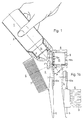
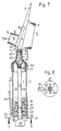
- the first embodiment shown in FIG. 1 has a storage container 1 designed as a handle part with an elastic, crushable and transparent wall 2.
- An application part 4 is screwed onto the container opening 3 of the storage container 1 and bears a projecting compartment tip 5, a comb part 6 with comb prongs 7 and a brush attachment 8.
- the compartment tip 5 forms an angle a of approximately 40 ° with the longitudinal axis of the storage container 1.
- the longitudinal axis of the comb teeth 7 forms an angle y of 75 ° with the longitudinal axis of the storage container 1.
- the longitudinal axis of the brush tufts 9 of the brush attachment 8 opposite the comb part forms an angle ⁇ of approximately 50 ° with the longitudinal axis of the storage container 1.
- the brush attachment 8 has, on the side facing the application part 4, a dovetail-shaped groove 10 which can be displaced on a dovetail-shaped spring 11 which is correspondingly formed on the application part 4 as a counterpart.
- the end of the dovetail-shaped spring 11 facing the storage container 1 carries one slot-shaped passage opening 13, which connects the interior 14 of the application part 4 with the interior of the storage container 1.
- the part of the brush attachment located above the passage opening 13 carries an elastic, slit-shaped rubber grommet 15 which, when the brush attachment 8 is removed, has been inserted from the dovetail-shaped groove 10 through a corresponding opening in the brush attachment 8.
- the slot-shaped rubber grommet 15 is surrounded by brush tufts 9 on both long sides and its outlet opening 15 b is surmounted by the latter.
- the application part 4 is unscrewed from the storage container 1 and the components of the hair color - hydrogen peroxide and the special hair color are filled in through the container opening 3.
- the quantity required can be read off on a scale attached to the outer wall of the container.
- the mixing position shown in FIG. 1a is obtained, in which the passage opening 13 is closed by the extension 10a.
- the components of the hair color are mixed with one another by kneading and shaking the wall 2.
- the brush attachment 8 is brought back into the order shown in FIG. 1 and the hair coloring process can thus be started.
- the user takes the hair color applicator in accordance with the working position shown in FIG.
- the slit-shaped rubber grommet 15 can take part in the brush movements at any time.
- the remaining hair color in the hair color applicator can be easily cleaned with warm water after removing the brush attachment 8 and after unscrewing the application part 4 from the storage container 1. Then the hair coloring process described above can be repeated as often as you like.
- the wall 2 of the storage container 1 made of material that is too stiff - generally injection-molded plastic - is used, it cannot be completely emptied when coloring the hair, as a result of which a certain residual amount must subsequently be rinsed out.
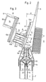
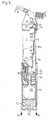
- the second embodiment shown in FIGS. 2 to 5 has the change or addition described below compared to the first embodiment.
- the application part 4 has slightly different geometric dimensions than that shown in FIG. 1.
- the compartment tip 5 forms an angle a of approximately 11 ° with the longitudinal axis of the storage container 1.
- the longitudinal axis of each comb prong 7 forms an angle y of approximately 82.5 ° with the longitudinal axis of the storage container 1.
- the longitudinal axis of each brush tuft 9 forms an angle a of approximately 70 ° with the longitudinal axis of the storage container 1.
- the storage container 1 has a cylindrical, transparent but solid wall 2, in the interior of which a piston 16 is arranged to be axially displaceable. With this piston, a piston rod 17 is axially fixed, but rotatably connected, which projects beyond the rear end of the storage container 1, as can be seen more clearly from FIGS. 4 and 5.
- the piston rod 17 carries on each of its diametrically opposite longitudinal sides a rack 19 and 20 which is firmly connected to it and which are fitted with sawtooth-shaped teeth 21.
- Claw-shaped extensions 23 of a transport device 22 engage in the teeth 21 of the piston rod 17 and are connected in an elastically resilient manner to a ring 24.
- the ring 24 is pressed in the direction of the free end 29 of the piston rod 17 by the compression spring 25, which is supported on the inner wall 26 of the closure cap 27.
- an actuating element 31 which comprises the piston rod 17 and is movably mounted about a swivel joint 32.
- the free end 33 of the actuating member 31 is connected in an articulated manner to an actuating rod 28 mounted on the outer wall of the storage container 1 in a cover 34 so as to be longitudinally displaceable.
- the actuating rod 28 has an actuating extension 35 at its end facing the application part 4, as can be seen from FIG. 4.
- the closure cap 27 is detachably screwed to the end of the storage container 1 remote from the application part 4 and is secured in a known manner against inadvertent unscrewing by an axially displaceable safety button (27a). (Fig. 5).
- a ball 37 fixed to a thread 36 with the piston 16 is arranged in the interior of the storage container 1 in the area between the piston 16 and the application part 4. Mixing the hair color is made considerably easier by this ball 37, as can be seen more clearly from FIG. 2. So that this ball 37 when necessary disassembly, e.g. when cleaning, not lost, it is secured against loss with the thread 36.
- the application part 4, which can optionally be removed from the storage container 1 has a pin 39 projecting axially in the direction of the storage container 1, the length of which is dimensioned such that when the application part 4 is placed between the ball 37 and the wall of the application part 4, a through opening 40 for the person to be exited Hair color remains free (Fig. 2).
- the end of the storage container 1 facing away from the application part 4 is optionally firmly closed by a closure cap 27 which has the inner wall 26 and the outer wall 30 and has an axial opening 41 for the piston rod 17.
- the axial opening 41 in the outer wall 30 carries two diametrically inwardly projecting projections 42 and 43, which cooperate with the side flanks of the racks 19 and 20 on the piston rod 17 such that by rotating the piston rod 17 - also in the piston 16, the does not have to turn - the transport position is set by 90 ° when one side tooth flank stops on the assigned side of the two projections 42 and 43 and when the other side tooth flank stops on the opposite side of the two projections 42 and 43 the filling position is set . In the filling position, the piston rod 17 with the piston 16 attached to it can be moved axially freely.
- the intermediate piece 46 carrying the screw thread 4a can optionally be removed from the remaining application part 4 by means of an additional screw thread 45.
- the end of the intermediate piece 46 facing the remaining application part 4 carries a threaded connector 47 with a smaller inside diameter in relation to the inner diameter of the container opening 3 of the storage container 1, rod 39 interacting with the ball 37 being firmly connected to the remaining part of the application part 4 (Fig. 2).
- the emptied storage container 1 with the intermediate piece 46 with its threaded connector 47 can now be placed directly on a large pack with the component to be filled and by overpressure, for. B. by a pump, with returning pistons 16 optionally filled until the end position shown in FIG. 5 is reached. If the storage container 1 is held with the intermediate piece 46 pointing downward, the ball 37 seals against the inner wall of the intermediate piece 46 due to the force of gravity and only opens when there is excess pressure.
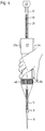
- a differently designed transport device 22 is used, in which the actuating member 31 has an actuating extension 35 projecting outwards, which in the rest position has an angle 8 of approximately 4 ° with the outer wall 2 of the storage container 1 .
- the arrangement is such that in the transport position when the actuating extension 35 is pressed against the outer wall 2 of the storage container 1, the piston rod 17 and the piston 16 connected therewith are transported in the direction of the application part 4.
- the actuation is essentially carried out by the ring finger and the smallest finger of the user.
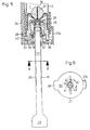
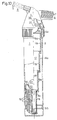
- the piston rod 17 is designed telescopically, in which the individual tube parts 18 forming the telescopic piston rod 17 each have an external or internal thread 18a, which engages in pairs, the piston 16 being fixed against rotation arranged in the cylindrical wall 2 and the end of the driven tube part 18 which is remote from the piston 16 is preferably connected in a rotationally fixed manner to the drive shaft 49 of the direct current motor 50.
- a preferably cylindrical housing part 51 containing the DC motor 50 and a rechargeable battery 52 can optionally be uncoupled from the storage container 1 by means of a coupling device for cleaning purposes.
- the inner wall of the housing part 51 faces the storage container 1.
- the housing part 51 has on its cylindrical outer side an axially displaceable, concentrically arranged locking sleeve 57, which is shown in FIG. 11 in the locking state.
- the inside of this locking sleeve 57 has a wide circumferential annular recess 59 which, when axially displaced against the force of a spring (not shown), comes to rest behind the knob-like projections 54 in the direction of arrow 60, as a result of which it is attached the counter member of the coupling device formed on the storage container 1 can spring the projections 54 radially outward until they engage in the annular groove 55 (FIG. 9).
- the spring not shown, the locking sleeve is released pushed back into the locking position shown.
- the battery 52 is recharged via the two contact springs 56 from a power supply charger, which is preferably designed as a stand, in the unused idle times.
- a power supply charger which is preferably designed as a stand, in the unused idle times.
- an actuation extension (not shown) (similar to the actuation extension 35 in FIG. 4) is also formed, via which an electrical switch for switching the DC motor 50 on and off is actuated.
Landscapes
- Cleaning And Drying Hair (AREA)
- Brushes (AREA)
- Cosmetics (AREA)
Abstract
Description
Die Erfindung betrifft ein Haarfarbeauftraggerät gemäß dem Oberbegriff in Patentanspruch 1.The invention relates to a hair color applicator according to the preamble of
Ein gattungsgleiches Haarfarbeauftraggerät ist beispielsweise aus der US-A 2 299 296 bekannt. Ein derartiges Gerät dient unter anderem zum Aufträgen einer Haarfarbe auf eine Haarsträhne mittels eines Auftrageteils, das mit einer Durchtrittsöffnung für eine Farbabgabe kommuniziert und wahlweise abnehmbar ist. Von Nachteil ist, daß in den Vorratsbehälter eine bereits gemischte Haarfarbe eingebracht werden muß, wodurch ein separater Mischbehälter benutzt werden muß. Ein weiterer Nachteil ist darin zu sehen, daß die Borstenbüschel ganz mit Farbe überflutet werden können, wodurch ein ungewolltes Tropfen der Farbe oder ein zu starker Farbauftrag auf Haarsträhnen resultiert.A hair dye applicator of the same type is known, for example, from US Pat. No. 2,299,296. Such a device is used, inter alia, for applying a hair color to a strand of hair by means of an application part which communicates with a passage opening for a color delivery and is optionally removable. The disadvantage is that an already mixed hair color must be introduced into the storage container, which means that a separate mixing container must be used. Another disadvantage is the fact that the tufts of bristles can be completely flooded with paint, which results in an unwanted dripping of the paint or too much paint on strands of hair.
Die Erfindung hat sich zur Aufgabe gestellt, eine neuartige Bauweise eines Haarfarbeauftragegerätes, insbesondere für cremeartige Haarfarbe anzugeben, bei der durch einfache konstruktive Maßnahmen der Befüllungs-, Misch- und Auftragevorgang erleichtert werden soll, wobei eine einwandfreie, ausreichende Farbmengenabgabe - insbesondere für den Haaransatz - erzielt werden soll.The invention has set itself the task of specifying a novel construction of a hair color application device, in particular for cream-like hair color, in which the filling, mixing and application process is to be facilitated by simple constructive measures, with a flawless, sufficient quantity of color - in particular for the hairline - should be achieved.
Diese Aufgabe wird gemäß der Erfindung durch das Kennzeichen des Patentanspruchs 1 gelöst. Durch die mittels des Bürstenaufsatzes verschlossene Durchtrittsöffnung kann beim Schütteln des Geräts zwecks Erzielung einer Flüssigkeitsmischung vorteilhafterweise keine Flüssigkeit unkontrolliert nach Außen treten, wodurch ein separater Mischbehälter eingespart wird. Zum Öffnen der Durchtrittsöffnung wird der Bürstenaufsatz verschoben, wodurch die Flüssigkeit mittels der schlitzförmige Gummitülle direkt bis nahe zu den freien Enden der Borstenbüschel für eine einwandfreie, ausreichende Flüssigkeitsabgabe gebracht wird, ohne die Elastizität der Bürste merklich einzuschränken.This object is achieved according to the invention by the characterizing part of
Es ist günstig, wenn eine Ausführungsform gemäß dem Kennzeichen des Unteranspruchs 8 ausgebildet ist. Es ist zweckmäßig, wenn diese Ausführungsform durch das Kennzeichen des Unteranspruchs 9 ergänzt wird.It is advantageous if an embodiment is designed according to the characterizing part of
Weitere Fortbildungen und Ausgestaltungen der Erfindung sind in den Unteransprüchen gekennzeichnet und werden nachstehend in Verbindung mit den Ausführungsbeispiele darstellenden, teilweise schematisch vereinfachten Figuren beschrieben. In diesen sind einander entsprechende Teile mit gleichen Bezugszeichen versehen, und es sind alle zum Verständnis der Erfindung nicht notwendigen Einzelheiten vorgelassen worden.Further developments and refinements of the invention are characterized in the subclaims and are described below in connection with the exemplary embodiments, partially schematically simplified figures. In these, corresponding parts are provided with the same reference numerals, and all details which are not necessary for understanding the invention have been provided.
Es zeigt:
- Fig. 1 eine teilweise geschnittene Seitenansicht einer ersten erfindungsgemäßen Ausführungsform, wobei der Behälter nicht vollständig, jedoch der Bürstenaufsatz in Auftragestellung dargestellt ist,
- Fig. 1a eine Seitenansicht eines Details der in Fig. 1 dargestellten Ausführungsform, bei der sich der Bürstenaufsatz in Mischstellung (verschlossene Austrittsöffnung) befindet,
- Fig. 2 eine teilweise geschnittene Seitenansicht einer zweiten erfindungsgemäßen Ausführungsform in entleerter Stellung wobei der Behälter nicht vollständig, jedoch der Bürstenaufsatz in Auftragestellung dargestellt ist,
- Fig. 3 den Bürstenaufsatz der in Fig. 2 gezeigten zweiten Ausführungsform, wobei die dargestellte Lage im Bezug auf Fig. 2 der Mischstellung entspricht,
- Fig. 4 eine Aufsicht, auf die um 90° gegenüber Fig. gedrehte zweite Ausführungsform in Arbeitsstellung bei der die Kammzinken auf die dem Betrachter zugewandten Seite oben zu liegen kommen und aus der die Arbeitshaltung beim Haarefärben ersichtlich ist,
- Fig. 5 einen Längsschnitt durch das vom Auftrageteil abgewendete Ende des Vorratsbehälters der in Fig. 2 gezeigten zweiten Ausführungsform jedoch in gefüllter Stellung und in einer Lage ähnlich Fig. 4,
- Fig. 6 einen Schnitt entlang der Linie A-B durch die in Fig. 5 gezeigten zweite Ausführungsform,
- Fig. 7 eine teilweise geschnittene Seitenansicht durch eine dritte erfindungsgemäße Ausführungsform in entleerter Stellung
- Fig. 8 einen Schnitt entlang der Linie C-D durch die in Fig. 7 gezeigte dritte Ausführungsform, und
- Fig. 9 eine teilweise geschnittene Seitenansicht einer weiteren Ausführungsform im zusammengekuppelten Zustand, wobei die linke Hälfte in gefüllter Stellung und die rechte Hälfte in entleerter Stellung dargestellt ist und der nicht vollständig dargestellte Auftrageteil demjenigen von Fig. 2 entspricht,
- Fig. 10 ein das eine Teil einer Koppelvorrichtung tragende Bauteil der in Fig. dargestellten Ausführungsform in vergrößertem Maßstab und
- Fig. 11 ein das andere Teil einer Koppelvorrichtung tragende Bauteil der in Fig. 9 dargestellten Ausführungsform in vergrößertem Maßstab.
- 1 is a partially sectioned side view of a first embodiment of the invention, the container is not shown completely, but the brush attachment is shown in the order,
- 1a is a side view of a detail of the embodiment shown in Fig. 1, in which the brush attachment is in the mixed position (closed outlet opening),
- 2 shows a partially sectioned side view of a second embodiment according to the invention in the emptied position, the container not being shown completely, but the brush attachment being shown in the order,
- 3 shows the brush attachment of the second embodiment shown in FIG. 2, the position shown in relation to FIG. 2 corresponding to the mixed position,
- 4 is a plan view of the second embodiment rotated by 90 ° with respect to FIG. 1 in the working position in which the comb teeth come to lie on the side facing the viewer and from which the working posture during hair dyeing can be seen,
- 5 shows a longitudinal section through the end of the storage container of the second embodiment shown in FIG. 2 facing away from the application part, but in the filled position and in a position similar to FIG. 4,
- 6 shows a section along the line AB through the second embodiment shown in FIG. 5,
- Fig. 7 is a partially sectioned side view through a third embodiment of the invention in the emptied position
- 8 shows a section along the line CD through the third embodiment shown in FIG. 7, and
- 9 is a partially sectioned side view of a further embodiment in the coupled state, the left half being shown in the filled position and the right half in the emptied position and the part of the application not shown completely corresponding to that of FIG. 2,
- 10 shows a part of a coupling device-carrying component of the embodiment shown in FIG. 1 on an enlarged scale and
- FIG. 11 shows a component of the embodiment shown in FIG. 9 carrying the other part of a coupling device on an enlarged scale.
Die in Figur 1 gezeigte erste Ausführungsform weist einen als Griffteil ausgebildeten Vorratsbehälter 1 mit einer elastischen, knautschbaren und durchsichtige Wandung 2 auf. Auf die Behälteröffnung 3 des Vorratsbehälters 1 ist ein Auftrageteil 4 aufgeschraubt, das eine vorragende Abteilspitze 5, ein Kammteil 6 mit Kammzinken 7 sowie einen Bürstenaufsatz 8 trägt. Die Abteilspitze 5 bildet mit der Längsachse des Vorratsbehälters 1 einen Winkel a von etwa 40°. Die Längsachse der Kammzinken 7 bilden mit der Längsachse des Vorratsbehälters 1 einen Winkel y von 75°. Während die Längsachse der Bürstenbüschel 9 des dem Kammteil gegenüberliegenden Bürstenaufsatz 8 mit der Längsachse des Vorratsbehälters 1 einen Winkel β von etwa 50° bildet. Der Bürstenaufsatz 8 weist auf der dem Auftrageteil 4 zugewendeten Seite eine schwalbenschwanzförmige Nut 10 auf, die auf einer entsprechend am Auftrageteil 4 als Gegenstück ausgebildeten schwalbenschwanzförmigen Feder 11 verschiebbar ist. Das dem Vorratsbehälter 1 zugewendete Ende der schwalbenschwanzförmigen Feder 11 trägt eine schlitzförmige Durchtrittsöffnung 13, die den Innenraum 14 des Aufrageteils 4 mit dem Innenraum des Vorratsbehälters 1 verbindet. Der über der Durchtrittsöffnung 13 liegende Teil des Bürstenaufsatzes trägt eine elastische schlitzförmige Gummitülle 15, die bei abgenommenen Bürstenaufsatz 8 von der schwalbenschwanzförmigen Nut 10 aus durch eine entsprechende Öffnung des Bürstenaufsatzes 8 eingesteckt worden ist. Die schlitzförmige Gummitülle 15 ist von beiden Längsseiten von Bürstenbüscheln 9 umgeben und ihre Austrittsöffnung 15 b wird von letzteren überragt.The first embodiment shown in FIG. 1 has a
Die Wirkung ist folgendermaßen:The effect is as follows:
Das Auftrageteil 4 wird vom Vorratsbehälter 1 abgeschraubt und durch die Behälteröffnung 3 die Bestandteile der Haarfarbe - Wasserstoffsuperoxyd sowie die spezielle Haarfarbe eingefüllt. Die jeweils benötigte Menge kann auf einer auf der Behälteraußenwandung angebrachten Skala abgelesen werden. Nach Aufschrauben des Auftrageteils 4 und Umstecken des Bürstenaufsatzes 8 erhält man die in Fig. 1a gezeigte Mischstellung, bei der die Durchtrittsöffnung 13 von dem Fortsatz 10a verschlossen wird. Durch Kneten und Schütteln der Wandung 2 werden die Komponenten der Haarfarbe miteinander vermischt. Danach wird der Bürstenaufsatz 8 wieder in die in Fig. 1 gezeigte Auftragestellung gebracht und der Haarfärbevorgang kann somit begonnen werden. Der Benutzer nimmt das Haarfarbeauftragegerät entsprechend der in Fig. 1 gezeigten Arbeitsstellung in die Hand, teilt mit der Abteilspitze 5 eine Haarsträhne ab, kämmt sie mit dem Kammteil 6 und trägt mit dem Bürstenaufsatz 8 unter leichtem Druck auf die Wandung 2 Haarfarbe auf die zu färbenden Haare auf. Hierbei wird die Haarfarbe durch die schlitzförmige Gummitülle 15 bis nahe zu den freien Enden der Bürstenbüschel 9 gebracht, wodurch insbesondere auch der Haaransatz ausreichend gefärbt werden kann. Durch ihre elastische Wandung kann die schlitzförmige Gummitülle 15 jederzeit die Bürstenbewegungen mitmachen.The
Nach erfolgter Haarfärbung kann die restliche im Haarfarbeauftragegerät verbliebene Haarfarbe leicht nach Abnehmen des Bürstenaufsatzes 8 und nach Abschrauben des Auftrageteils 4 vom Vorratsbehälter 1 mit warmem Wasser gereinigt werden. Danach kann der oben beschriebene Haarfärbevorgang beliebig oft wiederholt werden.After the hair has been colored, the remaining hair color in the hair color applicator can be easily cleaned with warm water after removing the
Damit beim Nachlassen des Druckes auf die Wandung 2 des Vorratsbehälters 1 der Druckausgleich sicher durch die schlitzförmige Gummihülle 15 erfolgen kann, sind in derem Inneren drei Längsstege 15a vorgesehen, die jeweils mit einer ihrer beiden Längswände fest verbunden sind. Zwischen diesen Längsstegen 15a kann bei im Inneren des Vorratsbehälters 1 erzeugtem Unterdruck die Luft zum Druckausgleich strömen, ohne daß ein Verkleben und somit ein Verschließen dieser Luftzutrittsöffnung eintritt.So that when the pressure on the
Wird die Wandung 2 des Vorratsbehälters 1 aus zu steifem Material - im allgemeinen spritzgegossenen Kunststoff - verwendet, kann dieser beim Haarfärben nicht völlig entleert werden, wodurch eine gewisse Restmenge anschließend ausgespült werden muß.If the
Um diesen Nachteil zu vermeiden, ist es günstig, wenn die nachfolgend beschriebene zweite erfindungsgemäße Ausführungsform verwendet wird.To avoid this disadvantage, it is advantageous if the second embodiment of the invention described below is used.
Die in Figur 2 bis 5 gezeigte zweite Ausführungsform weist gegenüber der ersten Ausführungsform nachfolgend beschriebene Änderung bzw. Ergänzung auf.The second embodiment shown in FIGS. 2 to 5 has the change or addition described below compared to the first embodiment.
Das Auftrageteil 4 besitzt etwas andere geometrische Abmessungen als das in Fig. 1 gezeigte. Hierbei bildet die Abteilsspitze 5 mit der Längsachse des Vorratsbehälters 1 einen Winkel a von etwa 11°. Die Längsachse jedes Kammzinken 7 bildet jeweils mit der Längsachse des Vorratsbehälters 1 einen Winkel y von etwa 82,5°. Während die Längsachse jedes Bürstenbüschels 9 mit der Längsachse des Vorratsbehälters 1 einen Winkel a von etwa 70° bildet. Der Vorratsbehälter 1 weist eine zylinderförmige durchsichtige jedoch feste Wandung 2 auf, in dessen Innerem ein Kolben 16 axial verschiebbar angeordnet ist. Mit diesem Kolben ist eine Kolbenstange 17 axial fest, jedoch drehbar verbunden, die über das hintere Ende des Vorratsbehälters 1 hinausragt, wie aus Fig. 4 und 5 besser ersichtlich.The
Die Kolbenstange 17 trägt an ihren diametral gegenüberliegenden Längsseiten je eine mit ihr fest verbundene Zahnstange 19 und 20, die mit sägezahnförmigen Zähnen 21 besetzt sind. In die Zähne 21 der Kolbenstange 17 greifen klauenförmige Fortsätze 23 einer Transportvorrichtung 22 ein, die elastisch federnd mit einem Ring 24 fest verbunden sind. Der Ring 24 wird durch die Druckfeder 25, die sich an der Innenwand 26 der Verschlußkappe 27 abstützt, in Richtung auf das freie Ende 29 der Kolbenstange 17 gedrückt. Im Zwischenraum zwischen Ring 24 und Außenwand 30 der Verschlußkappe 27 ist ein die Kolbenstange 17 umfaßendes Betätigungsglied 31 angeordnet, das um ein Drehgelenk 32 beweglich gelagert ist. Das freie Ende 33 des Betätigungsgliedes 31 ist mit einer an der Außenwand des Vorratsbehälters 1 in einer Abdeckung 34 längsverschiebbar gelagerten Betätigungsstange 28 gelenkig verbunden. Die Betätigungsstange 28 weist an ihrem dem Auftrageteil 4 zugewendeten Ende einen Betätigungsfortsatz 35 auf, wie aus Figur 4 ersichtlich.The
Bei Verschieben des Betätigungsfortsatzes 35 in Richtung auf das Auftrageteil 4 wird der Ring 24 und damit die klauenförmigen Fortsätze 23 in gleicher Richtung bewegt. Durch die sägezahnförmigen Zähne 21 wird in bekannter Weise die Kolbenstange in gleicher Richtung mitgenommen. Beim Loslassen des Betätigungsfortsatzes 35 drückt die Druckfeder 25 den Ring 24 in die Ausgangsstellung zurück, wobei die klauenförmigen Fortsätze 23 aus den Zähnen 21 ausklinken und hinter dem entsprechend nächsten bzw. nachstfolgenden Zahn 21 wieder einrasten. Durch jeden Betätigungshub des Betätigungsfortsatzes 35 erfolgt somit eine entsprechende Vorwärtsbewegung des Kolbens 16 in Richtung auf das Auftrageteil 4, wobei die im Inneren des Vorratsbehälters 1 enthaltene Haarfarbe über den Innenraum 14 zur Austrittsöffnung 15b des Bürstenaufsatzes 8 befördert wird.When the
Die Verschlußkappe 27 ist mit dem von dem Auftrageteil 4 entfernt liegenden Ende des Vorratsbehälters 1 lösbar verschraubt und durch eine axial verschiebbare Sicherungstaste (27a) in bekannter Weise gegen unbeabsichtigtes Abschrauben gesichert. (Fig. 5).The
Im Inneren des Vorratsbehälters 1 im Bereich zwischen Kolben 16 und Auftrageteil 4 ist eine an einem Faden 36 mit dem Kolben 16 fest verbundene Kugel 37 angeordnet. Durch diese Kugel 37 wird das Durchmischen der Haarfarbe erheblich erleichtert, wie aus Fig. 2 besser ersichtlich. Damit diese Kugel 37 bei einer erforderlichen Demontage, z.B. beim Reinigen, nicht verlorengeht, ist diese mit dem Faden 36 gegen Verlust gesichert. Weiterhin weist das vom Vorratsbehälter 1 wahlweise abnehmbare Auftrageteil 4 im Innern einen in Richtung auf den Vorratsbehälter 1 axial vorragenden Stift 39 auf, dessen Länge derart bemessen ist, daß bei aufgesetztem Auftrageteil 4 zwischen Kugel 37 und Wandung des Auftrageteils 4 eine Durchgangsöffnung 40 für die auszutretende Haarfarbe frei bleibt (Fig. 2).In the interior of the
Wie aus Fig. 5 und 6 besser ersichtlich ist, ist das vom Auftrageteil 4 abgewandte Ende des Vorratsbehälters 1 wahlweise durch eine die Innenwand 26 und die Außenwand 30 aufweisende Verschlußkappe 27 fest verschlossen, die eine axiale Öffnung 41 für die Kolbenstange 17 aufweist. Die axiale Öffnung 41 in der Außenwand 30 trägt zwei diametral nach innen vorragende Vorsprünge 42 bzw. 43, die mit den seitlichen Flanken der Zahnstangen 19 und 20 an der Kolbenstange 17 derart zusammenwirken, daß durch Verdrehen der Kolbenstange 17 - auch im Kolben 16, der sich nicht mitdrehen muß - um jeweils 90° bei Anschlag der einen seitlichen Zahnflanke an die zugeordnete Seite der beiden Vorsprünge 42 und 43 die Transportstellung eingestellt und bei Anschlag der jeweils anderen seitlichen Zahnflanke an die gegenüberliegende Seite der beiden Vorsprünge 42 und 43 die Füllstellung eingestellt ist. In der Füllstellung ist die Kolbenstange 17 mit dem daran befestigten Kolben 16 axial frei bewegbar.5 and 6, the end of the
Dass das Schraubgewinde 4a tragende Zwischenstück 46 ist mittels eines zusätzlichen Schraubengewindes 45 von dem übrigen Auftrageteil 4 wahlweise abnehmbar. Hierbei trägt das dem übrigen Auftrageteil 4 zugewandte Ende des Zwischenstückes 46 einen Gewindestutzen 47 mit einer in bezug auf den Innendurchmesser der Behälteröffnung 3 des Vorratsbehälters 1 kleineren lichten Durchmesser, wobei mit der Kugel 37 zusammenwirkende Stab 39 mit dem restlichen Teil des Auftrageteils 4 fest verbunden ist (Fig. 2). Beispielsweise kann jetzt der entleerte Vorratsbehälter 1 mit dem Zwischenstück 46 mit seinem Gewindestutzen 47 direkt auf eine Großpackung mit der zu füllenden Komponente aufgesetzt werden und durch Überdruck, z. B. durch eine Pumpe, bei zurückgleitenden Kolben 16 wahlweise so lange gefüllt werden, bis die in Fig. 5 gezeigte Endstellung erreicht ist. Wird der Vorratsbehälter 1 mit nach unten zeigender Zwischenstück 46 gehalten, so dichtet die Kugel 37 aufgrund der Schwerkraft mit der Innenwandung des Zwischenstückes 46 ab und öffnet nur bei Überdruck.The
Bei einer in Fig. 7 und 8 dargestellten dritten Ausführungsform wird eine anders ausgebildete Transportvorrichtung 22 verwendet, bei der das Betätigungsglied 31 einen nach außen vorragenden Betätigungsfortsatz 35 aufweist, der in Ruhestellung mit der Außenwand 2 des Vorratsbehälters 1 einen Winkel 8 von etwa 4° aufweist. Die Anordnung ist hierbei derart getroffen, daß in Transportstellung beim Andrücken des Betätigungsfortsatzes 35 an die Außenwand 2 des Vorratsbehälters 1 ein Transport der Kolbenstange 17 sowie des damit verbundenen Kolbens 16 in Richtung auf das Auftrageteil 4 hin erfolgt. Die Betätigung erfolgt in diesem Fall im wesentlichen durch den Ringfinger und den kleinsten Finger des Benutzers.In a third embodiment shown in FIGS. 7 and 8, a differently designed
Bei einer weiteren Ausführungsform gemäß Fig. 9 bis 11 ist abweichend, die Kolbenstange 17 teleskopartig ausgebildet, bei der die einzelnen, die teleskopartige Kolbenstange 17 bildenden Rohrteile 18 ein jeweils paarweise im Eingriff stehendes Außen- bzw. Innengewinde 18a aufweisen, wobei der Kolben 16 verdrehfest in der zylinderförmigen Wandung 2 angeordnet und das vom Kolben 16 entfernt liegende Ende des angetriebenen Rohrteiles 18 vorzugsweise mit der Antriebswelle 49 des Gleichstrommotors 50 verdrehfest verbunden ist. Zusätzlich ist ein den Gleichstrommotor 50 und eine wiederaufladbare Batterie 52 enthaltendes, vorzugsweise zylindrisches Gehäuseteil 51 wahlweise zu Reinigungszwecken vom Vorratsbehälter 1 mittels einer Koppelvorrichtung abkuppelbar.In a further embodiment according to FIGS. 9 to 11, the
Die Innenwand des Gehäuseteils 51 (Fig. 11) weist an ihrer dem Vorratsbehälter 1 zugewende-. ten Seite sich axial erstreckende rippenförmige Kupplungsklauen 53 mit je einem radial nach innen vorragenden noppenartigen Vorsprung 54 auf, die mit einer entsprechend am Vorratsbehälter 1 ausgebildeten Ringnut 55 als Koppelvorrichtung zusammenwirken.The inner wall of the housing part 51 (FIG. 11) faces the
Das Gehäuseteil 51 weist an seiner zylindrischen Außenseite eine darauf axial verschiebbare, konzentrisch angeordnete Verriegelungshülse 57 auf, die in Fig. 11 in verriegelnden Zustand dargestellt ist. Im mittleren Bereich der rippenförmigen Kupplungsklauen 53 weist die Innenseite dieser Verrieglungshülse 57 eine breite umlaufende ringförmige Ausnehmung 59 auf, die bei axialem Verschieben gegen die Kraft einer nicht dargestellten Feder in Richtung des Pfeiles 60 hinter den noppenartigen Vorsprüngen 54 zu liegen kommt, wodurch beim Aufstecken auf das am Vorratsbehälter 1 ausgebildete Gegenglied der Koppelvorrichtung die Vorsprünge 54 radial nach au- ßen federn können, bis diese in der Ringnut 55 (Fig. 9) einrasten. Durch die nicht dargestellte Feder wird beim Loslassen die Verriegelungshülse in die gezeigte Verriegelungsstellung zurückgedrückt.The
Die Batterie 52 wird über die beiden Kontaktfedern 56 aus einem vorzugsweise als Ständer ausgebildeten Ladegerät aus dem Stromnetz in den nichtbenutzten Standzeiten wieder aufgeladen. Am Vorratsbehälter 1 ist weiterhin ein nicht dargestellter Betätigungsfortsatz (ähnlich Betätigungsfortsatz 35 in Fig. 4) ausgebildet, über den ein elektrischer Schalter zum Ein- und Ausschalten des Gleichstrommotors 50 betätigt wird.The
Claims (21)
Priority Applications (1)
| Application Number | Priority Date | Filing Date | Title |
|---|---|---|---|
| AT81102669T ATE49341T1 (en) | 1980-04-10 | 1981-04-09 | HAIR COLOR APPLICATOR. |
Applications Claiming Priority (2)
| Application Number | Priority Date | Filing Date | Title |
|---|---|---|---|
| DE3013769A DE3013769C2 (en) | 1980-04-10 | 1980-04-10 | Hair color applicator |
| DE3013769 | 1980-04-10 |
Publications (3)
| Publication Number | Publication Date |
|---|---|
| EP0038024A2 EP0038024A2 (en) | 1981-10-21 |
| EP0038024A3 EP0038024A3 (en) | 1986-09-03 |
| EP0038024B1 true EP0038024B1 (en) | 1990-01-10 |
Family
ID=6099655
Family Applications (1)
| Application Number | Title | Priority Date | Filing Date |
|---|---|---|---|
| EP81102669A Expired - Lifetime EP0038024B1 (en) | 1980-04-10 | 1981-04-09 | Hair-dye applying apparatus |
Country Status (5)
| Country | Link |
|---|---|
| US (1) | US4592376A (en) |
| EP (1) | EP0038024B1 (en) |
| JP (1) | JPS56151005A (en) |
| AT (1) | ATE49341T1 (en) |
| DE (2) | DE3013769C2 (en) |
Cited By (2)
| Publication number | Priority date | Publication date | Assignee | Title |
|---|---|---|---|---|
| US6145513A (en) * | 1999-02-26 | 2000-11-14 | New Basics, Inc. | Hair dye applicator |
| USD519674S1 (en) | 2003-10-17 | 2006-04-25 | New Basics, Inc. | Hair fluid applicator |
Families Citing this family (37)
| Publication number | Priority date | Publication date | Assignee | Title |
|---|---|---|---|---|
| US4605026A (en) * | 1983-04-06 | 1986-08-12 | Nolin Rosemary D | Comb for dispensing treatment solution to hair |
| GB2174356A (en) * | 1985-05-03 | 1986-11-05 | Albyn Of Stonehaven Limited | Container with closure and spreader |
| DE3604811A1 (en) * | 1986-02-15 | 1987-08-20 | Leo Bussmeier | Device for handling liquid cosmetic products when treating the hair |
| DE3640352A1 (en) * | 1986-11-26 | 1988-06-09 | Leo Bussmeier | DEVICE FOR HANDLING LIQUIDS FOR THE TREATMENT OF THE HAIR AND FOR THE SAME APPLICATION |
| US4859105A (en) * | 1986-12-22 | 1989-08-22 | Davis Richard E | Applicator bottle |
| DE3702166A1 (en) * | 1987-01-26 | 1988-08-04 | Henkel Kgaa | HAIR FIBER DEVICE |
| DE3702167A1 (en) * | 1987-01-26 | 1988-08-04 | Henkel Kgaa | HAIR FIBER DEVICE |
| DE3702165A1 (en) * | 1987-01-26 | 1988-08-04 | Henkel Kgaa | HAIR FIBER DEVICE |
| US4813439A (en) * | 1987-06-09 | 1989-03-21 | Susan Morgan | Hair treatment solution applicator |
| US4846201A (en) * | 1987-10-20 | 1989-07-11 | Fuchs Kathryn J | Applicator bottle with metering means |
| DE3803692C1 (en) * | 1988-02-08 | 1989-04-27 | Henkel Kgaa, 4000 Duesseldorf, De | |
| JPH0290703U (en) * | 1988-12-28 | 1990-07-18 | ||
| US5056480A (en) * | 1990-09-28 | 1991-10-15 | Murray Sr Ralph | Liquid comb combination and method for its manufacture |
| US5289833A (en) * | 1992-03-19 | 1994-03-01 | Mcdonald Charles E | Multi-toothed dispenser, comb applicator and bottle |
| US5195545A (en) * | 1992-04-27 | 1993-03-23 | Thibodeaux Gregory W | Hair relaxant applicator apparatus |
| US5301695A (en) * | 1992-10-19 | 1994-04-12 | Wong Hilda C | Brush and method for hair treatment using bristle arrays of different densities and materials |
| US5307825A (en) * | 1993-01-13 | 1994-05-03 | Solomon Smith | Hair grooming device |
| IL120821A (en) * | 1997-05-11 | 2000-07-16 | Sofer Menachem | Hair dye dispenser |
| FR2782614B1 (en) * | 1998-09-01 | 2000-11-24 | Michel Laporte | DEVICE FOR APPLYING A PRODUCT TO HAIR, PARTICULARLY A COLORING PRODUCT |
| US5937864A (en) * | 1998-09-25 | 1999-08-17 | Diaz; Donne'j. | Hair coloring applicator with mixing chamber |
| US5913314A (en) * | 1998-10-05 | 1999-06-22 | Garrett; Michelle R. | Combination salon tool device |
| AU1051299A (en) | 1998-11-10 | 2000-05-29 | Montec Product Development Ltd. | Hair dye dispenser |
| US6915807B2 (en) * | 2000-02-23 | 2005-07-12 | Young Sik Choi | Hair setting device |
| DE10022565B4 (en) * | 2000-05-10 | 2013-10-02 | 3M Deutschland Gmbh | Device with telescopic piston |
| USD445953S1 (en) | 2000-07-07 | 2001-07-31 | Lynda L Smith | Hair care bottle with applicator |
| US20030140935A1 (en) * | 2002-01-30 | 2003-07-31 | Del Monte Anthony W. | Personal hairdresser |
| CA2493537A1 (en) * | 2002-07-25 | 2004-02-05 | Jae-Kun Lee | Dye container and hair dyeing device using the same |
| US20050133055A1 (en) * | 2002-08-19 | 2005-06-23 | Gus Stankovic | Fluid dispensing brush |
| US7044137B2 (en) * | 2002-08-23 | 2006-05-16 | Appliances Development Corporation | Hair treating device |
| HRP20030802A2 (en) * | 2003-10-03 | 2005-04-30 | Vrus-Pervan Iris | Precise hair colouring implement to form frosted and streaky hair and the method for protecting uncoloured hair |
| DE102004042617B4 (en) | 2004-09-01 | 2009-03-05 | Henkel Ag & Co. Kgaa | Applicator and hair treatment agent container |
| US20100095974A1 (en) * | 2008-10-21 | 2010-04-22 | Catherine Ann Laje | Tool for applying hair color |
| USD640470S1 (en) | 2010-08-10 | 2011-06-28 | Rose Spagnuolo | Hair highlighter nozzle |
| US8220469B1 (en) | 2010-12-01 | 2012-07-17 | Rose Spagnuolo | Hair highlighting applicator nozzle |
| FR3026282B1 (en) * | 2014-09-25 | 2016-12-09 | Oreal | APPLICATION SYSTEM FOR APPLYING A PRODUCT TO HAIR. |
| CN108851464B (en) * | 2018-07-12 | 2020-12-15 | 重庆市龙凤工艺品有限公司 | Folding comb |
| US12256821B1 (en) * | 2021-02-02 | 2025-03-25 | Colleen Garey | Scalp applicator |
Family Cites Families (38)
| Publication number | Priority date | Publication date | Assignee | Title |
|---|---|---|---|---|
| FR792254A (en) * | 1935-07-08 | 1935-12-26 | Brilliantine comb or other liquid product | |
| US2171591A (en) * | 1935-09-05 | 1939-09-05 | Henry D Minich | Brush |
| US2243774A (en) * | 1939-12-22 | 1941-05-27 | Victor J Resh | Dispensing device |
| US2313184A (en) * | 1940-09-25 | 1943-03-09 | Wadsworth Gordon | Combination toilet preparations dispenser |
| US2299295A (en) * | 1941-06-06 | 1942-10-20 | Joseph J Battle | Hair operator's instrument |
| US2299296A (en) * | 1941-10-21 | 1942-10-20 | Joseph J Battle | Hair operator's instrument |
| US2367346A (en) * | 1942-02-03 | 1945-01-16 | Pecora Paint Company | Calking gun and operating mechanism therefor |
| FR997257A (en) * | 1945-06-27 | 1952-01-03 | Liquid application device | |
| US2591831A (en) * | 1948-12-10 | 1952-04-08 | Gilbert B Knuff | Crayon or the like holder and feeding tube |
| FR1001756A (en) | 1949-12-01 | 1952-02-27 | Blush dispenser | |
| US2617431A (en) * | 1951-01-29 | 1952-11-11 | Gaspari Joseph | Hair-treating implement |
| US2768768A (en) * | 1953-02-27 | 1956-10-30 | Gibson Homans Company | Calking gun |
| DE1708738U (en) | 1953-09-24 | 1955-10-13 | Ewald Krauter | HAND APPLIANCE FOR TREATMENT OF HAIR WITH LIQUID OR PASTE-LIKE AGENTS, IN PARTICULAR FOR COLORING AND BLEACHING. |
| GB775900A (en) * | 1954-11-05 | 1957-05-29 | W A Mclellan Ltd | A combined washing and cleaning appliance for hand use |
| US2784603A (en) * | 1955-04-18 | 1957-03-12 | Harold B Collins | Holding means for calking gun plunger rods |
| US2793792A (en) * | 1955-04-19 | 1957-05-28 | James B Pilkington | Toothpaste dispenser |
| US2819723A (en) * | 1955-05-31 | 1958-01-14 | Jean Leclabart | Hair dyeing apparatus |
| US2845805A (en) * | 1957-09-18 | 1958-08-05 | Crewe Samuel | Duplex ratchet mechanism for calk guns |
| US2865383A (en) * | 1957-11-18 | 1958-12-23 | Kaley Flora Mcdougall | Apparatus for applying lotions, dyes, bleaches or like liquids to the hair roots or to the scalp |
| FR1258361A (en) * | 1960-03-02 | 1961-04-14 | Applicator with reservoir, in particular for hair dyes | |
| US3119142A (en) * | 1962-05-02 | 1964-01-28 | Kenneth E Fletcher | Fountain brush |
| US3402730A (en) * | 1965-05-24 | 1968-09-24 | Paul A. Lawrence | Hair-grooming device |
| FR1543996A (en) * | 1967-07-10 | 1968-10-31 | Hand gun for spraying putty | |
| US3517668A (en) * | 1967-10-16 | 1970-06-30 | Bio Neering Inc | Multiple dosage veterinary injection gun |
| DE1910433A1 (en) * | 1969-03-01 | 1970-09-10 | Scheel Dipl Ing Tilo | Device for applying liquid or paste-like agents |
| DE1959334A1 (en) * | 1969-11-26 | 1971-06-16 | Erwin Schuetz | Device as an accessory when laying perms |
| US3896822A (en) * | 1971-04-05 | 1975-07-29 | Eli Zimmerman | Brush applicator device |
| US3741310A (en) * | 1971-11-10 | 1973-06-26 | Kidde & Co Walter | Safety head arrangement for fire extinguisher |
| US3768691A (en) * | 1972-03-06 | 1973-10-30 | American Hospital Supply Corp | Disposable flatware container |
| DE2227930C2 (en) * | 1972-06-08 | 1974-04-18 | Rudolf 7057 Winnenden Blieberger | Spray device, especially for putty |
| FR2255869B1 (en) * | 1972-12-29 | 1977-10-28 | Shiseido Co Ltd | |
| US3973528A (en) * | 1975-02-28 | 1976-08-10 | Clairol Incorporated | Styling apparatus for hair |
| US4090522A (en) * | 1976-01-14 | 1978-05-23 | Donley Virgil L | Medicated comb for dandruff and other hair and scalp diseases |
| US4044724A (en) * | 1976-05-13 | 1977-08-30 | Hindes Limited | Grooming and dispensing brush head |
| US4294270A (en) * | 1977-09-19 | 1981-10-13 | Cochran Loretta L | Hair treating fluid applicator |
| DE2749074C2 (en) * | 1977-11-02 | 1988-01-21 | Fritz 8900 Augsburg Röhm | Hair dye |
| DE7927641U1 (en) * | 1979-09-28 | 1980-02-14 | Roehm, Fritz, 8900 Augsburg | HAIR FIBER DEVICE |
| US4331266A (en) * | 1980-07-03 | 1982-05-25 | Liqui-Box Corporation | Finger-actuated slideable-gate dispensing valve |
-
1980
- 1980-04-10 DE DE3013769A patent/DE3013769C2/en not_active Expired
-
1981
- 1981-03-23 JP JP4384781A patent/JPS56151005A/en active Pending
- 1981-04-03 US US06/250,704 patent/US4592376A/en not_active Expired - Fee Related
- 1981-04-09 AT AT81102669T patent/ATE49341T1/en not_active IP Right Cessation
- 1981-04-09 EP EP81102669A patent/EP0038024B1/en not_active Expired - Lifetime
- 1981-04-09 DE DE8181102669T patent/DE3177142D1/en not_active Expired - Fee Related
Cited By (2)
| Publication number | Priority date | Publication date | Assignee | Title |
|---|---|---|---|---|
| US6145513A (en) * | 1999-02-26 | 2000-11-14 | New Basics, Inc. | Hair dye applicator |
| USD519674S1 (en) | 2003-10-17 | 2006-04-25 | New Basics, Inc. | Hair fluid applicator |
Also Published As
| Publication number | Publication date |
|---|---|
| DE3177142D1 (en) | 1990-02-15 |
| ATE49341T1 (en) | 1990-01-15 |
| JPS56151005A (en) | 1981-11-21 |
| DE3013769C2 (en) | 1982-12-02 |
| US4592376A (en) | 1986-06-03 |
| EP0038024A2 (en) | 1981-10-21 |
| DE3013769A1 (en) | 1981-10-15 |
| EP0038024A3 (en) | 1986-09-03 |
Similar Documents
| Publication | Publication Date | Title |
|---|---|---|
| EP0038024B1 (en) | Hair-dye applying apparatus | |
| DE3610329C2 (en) | ||
| DE60126246T2 (en) | Material dispenser with applicator | |
| DE202018102538U1 (en) | Easily portable body trimmer with an inseparable comb attachment | |
| DE3884025T2 (en) | Brush. | |
| DE2318868C2 (en) | Device for applying a hair dye | |
| DE1782586A1 (en) | Manicure device | |
| DE2749074C2 (en) | Hair dye | |
| DE3814304A1 (en) | APPLICATION DEVICE | |
| EP0045370A2 (en) | Apparatus for partially dying the hair | |
| DE60316571T2 (en) | HAIR COLORING DEVICE WITH REMOVABLE BASE PART | |
| EP0276714A2 (en) | Hair-tinting apparatus | |
| DE870816C (en) | Hand paint press | |
| DE60115836T2 (en) | DEVICE FOR APPLYING AN ADDITIVE TO HAIR | |
| DE19828557C2 (en) | toothbrush | |
| DE2354236A1 (en) | Toothbrush with toothpaste magazine - has mechanism to press toothpaste out of magazine via channel to bristle end | |
| DE3050401C2 (en) | ||
| DE19647617A1 (en) | Dispensing and applying hair tint comprising two constituents | |
| DE7908402U1 (en) | SINGLE-HANDED DISPENSER FOR PASTE-LIKE SUBSTANCES | |
| EP0180019A2 (en) | Container for pasty substances and closure therefor | |
| CH300537A (en) | Dental care device. | |
| DE102011003121A1 (en) | Paint roller handpiece and paint applicator with such a paint roller hand piece | |
| DE613399C (en) | Toothbrush with dentifrice container | |
| DE532064C (en) | Application brush with paste feed | |
| DE8009816U1 (en) | HAIR COLOR APPLICATOR |
Legal Events
| Date | Code | Title | Description |
|---|---|---|---|
| PUAI | Public reference made under article 153(3) epc to a published international application that has entered the european phase |
Free format text: ORIGINAL CODE: 0009012 |
|
| AK | Designated contracting states |
Designated state(s): AT BE CH DE FR GB IT NL SE |
|
| 17P | Request for examination filed |
Effective date: 19810925 |
|
| PUAL | Search report despatched |
Free format text: ORIGINAL CODE: 0009013 |
|
| AK | Designated contracting states |
Kind code of ref document: A3 Designated state(s): AT BE CH DE FR GB IT LI NL SE |
|
| 17Q | First examination report despatched |
Effective date: 19890104 |
|
| GRAA | (expected) grant |
Free format text: ORIGINAL CODE: 0009210 |
|
| AK | Designated contracting states |
Kind code of ref document: B1 Designated state(s): AT BE CH DE FR GB IT LI NL SE |
|
| PG25 | Lapsed in a contracting state [announced via postgrant information from national office to epo] |
Ref country code: SE Effective date: 19900110 Ref country code: NL Effective date: 19900110 Ref country code: GB Effective date: 19900110 Ref country code: BE Effective date: 19900110 |
|
| REF | Corresponds to: |
Ref document number: 49341 Country of ref document: AT Date of ref document: 19900115 Kind code of ref document: T |
|
| ITF | It: translation for a ep patent filed | ||
| REF | Corresponds to: |
Ref document number: 3177142 Country of ref document: DE Date of ref document: 19900215 |
|
| PG25 | Lapsed in a contracting state [announced via postgrant information from national office to epo] |
Ref country code: AT Effective date: 19900409 |
|
| PG25 | Lapsed in a contracting state [announced via postgrant information from national office to epo] |
Ref country code: LI Effective date: 19900430 Ref country code: CH Effective date: 19900430 |
|
| ET | Fr: translation filed | ||
| NLV1 | Nl: lapsed or annulled due to failure to fulfill the requirements of art. 29p and 29m of the patents act | ||
| GBV | Gb: ep patent (uk) treated as always having been void in accordance with gb section 77(7)/1977 [no translation filed] | ||
| PLBE | No opposition filed within time limit |
Free format text: ORIGINAL CODE: 0009261 |
|
| STAA | Information on the status of an ep patent application or granted ep patent |
Free format text: STATUS: NO OPPOSITION FILED WITHIN TIME LIMIT |
|
| 26N | No opposition filed | ||
| REG | Reference to a national code |
Ref country code: CH Ref legal event code: PL |
|
| ITTA | It: last paid annual fee | ||
| PGFP | Annual fee paid to national office [announced via postgrant information from national office to epo] |
Ref country code: FR Payment date: 19940322 Year of fee payment: 14 |
|
| PGFP | Annual fee paid to national office [announced via postgrant information from national office to epo] |
Ref country code: DE Payment date: 19940329 Year of fee payment: 14 |
|
| PG25 | Lapsed in a contracting state [announced via postgrant information from national office to epo] |
Ref country code: FR Effective date: 19951229 |
|
| PG25 | Lapsed in a contracting state [announced via postgrant information from national office to epo] |
Ref country code: DE Effective date: 19960103 |
|
| REG | Reference to a national code |
Ref country code: FR Ref legal event code: ST |