EP0029476A1 - Rührwerk - Google Patents
Rührwerk Download PDFInfo
- Publication number
- EP0029476A1 EP0029476A1 EP80100216A EP80100216A EP0029476A1 EP 0029476 A1 EP0029476 A1 EP 0029476A1 EP 80100216 A EP80100216 A EP 80100216A EP 80100216 A EP80100216 A EP 80100216A EP 0029476 A1 EP0029476 A1 EP 0029476A1
- Authority
- EP
- European Patent Office
- Prior art keywords
- lantern
- agitator
- shaft
- seal
- lifting
- Prior art date
- Legal status (The legal status is an assumption and is not a legal conclusion. Google has not performed a legal analysis and makes no representation as to the accuracy of the status listed.)
- Withdrawn
Links
- 238000007789 sealing Methods 0.000 claims abstract description 26
- 210000004907 gland Anatomy 0.000 claims abstract description 6
- 238000003756 stirring Methods 0.000 claims description 10
- 230000005540 biological transmission Effects 0.000 description 14
- 238000012856 packing Methods 0.000 description 9
- 230000008878 coupling Effects 0.000 description 8
- 238000010168 coupling process Methods 0.000 description 8
- 238000005859 coupling reaction Methods 0.000 description 8
- 238000013461 design Methods 0.000 description 8
- 238000011161 development Methods 0.000 description 4
- 238000012549 training Methods 0.000 description 3
- 238000005452 bending Methods 0.000 description 2
- 230000008901 benefit Effects 0.000 description 2
- 238000010276 construction Methods 0.000 description 2
- 238000004519 manufacturing process Methods 0.000 description 2
- 238000012986 modification Methods 0.000 description 2
- 230000004048 modification Effects 0.000 description 2
- 239000000126 substance Substances 0.000 description 2
- 238000013459 approach Methods 0.000 description 1
- 229910010293 ceramic material Inorganic materials 0.000 description 1
- 230000008859 change Effects 0.000 description 1
- 230000001427 coherent effect Effects 0.000 description 1
- 230000001419 dependent effect Effects 0.000 description 1
- 238000006073 displacement reaction Methods 0.000 description 1
- 238000000605 extraction Methods 0.000 description 1
- 210000003746 feather Anatomy 0.000 description 1
- 238000007667 floating Methods 0.000 description 1
- 239000011521 glass Substances 0.000 description 1
- 230000002706 hydrostatic effect Effects 0.000 description 1
- 238000009434 installation Methods 0.000 description 1
- 238000005461 lubrication Methods 0.000 description 1
- 239000002184 metal Substances 0.000 description 1
- 238000000034 method Methods 0.000 description 1
- 231100000614 poison Toxicity 0.000 description 1
- 230000008569 process Effects 0.000 description 1
- 230000008439 repair process Effects 0.000 description 1
- 238000009420 retrofitting Methods 0.000 description 1
- 239000011435 rock Substances 0.000 description 1
- 238000000926 separation method Methods 0.000 description 1
- 238000003860 storage Methods 0.000 description 1
- 239000003440 toxic substance Substances 0.000 description 1
- 238000012546 transfer Methods 0.000 description 1
- 238000003466 welding Methods 0.000 description 1
Images


Classifications
-
- B—PERFORMING OPERATIONS; TRANSPORTING
- B01—PHYSICAL OR CHEMICAL PROCESSES OR APPARATUS IN GENERAL
- B01F—MIXING, e.g. DISSOLVING, EMULSIFYING OR DISPERSING
- B01F35/00—Accessories for mixers; Auxiliary operations or auxiliary devices; Parts or details of general application
- B01F35/40—Mounting or supporting mixing devices or receptacles; Clamping or holding arrangements therefor
- B01F35/41—Mounting or supporting stirrer shafts or stirrer units on receptacles
- B01F35/411—Mounting or supporting stirrer shafts or stirrer units on receptacles by supporting only one extremity of the shaft
- B01F35/4111—Mounting or supporting stirrer shafts or stirrer units on receptacles by supporting only one extremity of the shaft at the top of the receptacle
-
- B—PERFORMING OPERATIONS; TRANSPORTING
- B01—PHYSICAL OR CHEMICAL PROCESSES OR APPARATUS IN GENERAL
- B01F—MIXING, e.g. DISSOLVING, EMULSIFYING OR DISPERSING
- B01F35/00—Accessories for mixers; Auxiliary operations or auxiliary devices; Parts or details of general application
- B01F35/10—Maintenance of mixers
Definitions
- the invention relates to a stirrer intended for tight attachment to a container with filling to be stirred, with an attachment flange, a stirring shaft carrying a stirring tool, driven at its end facing away from the container (rear end) and with sealing elements arranged on the side of the attachment flange facing away from the container Sealing of the agitator shaft with respect to the interior of the container, a distance between the mounting flange and the drive elements of the agitator shaft being bridged by a supporting intermediate housing (lantern).
- the overall structure, in particular the drive design was generally a gearbox reducing the speed of an electric motor included, included in the problem associated with the easy interchangeability of the seals.
- the gearbox was seated on the support housing, which was designated as a lantern and had a window for the lateral removal of the seal, the lower part of which also surrounded the seal's own special housing, preferably a mechanical seal.
- a support housing (lantern) with a window for laterally removing only the inner wear parts of the mechanical seal was placed on the gear housing, but now only for storing and carrying, in particular the axial lifting of the gear output shaft with the inner ones Threaded elements enabling sealing elements are used.
- the separation of the formed here as a hollow shaft of the agitator shaft etriebeabtriebswelle G was carried out by removing a shaft passing through the hollow from the top is screwed into a cone of the agitator shaft anchor.
- the applicant further proposed a supporting element for the old seal to be removed and the new seal to be installed, appropriately height-adjustable on the support frame (lantern) about a vertical axis to be stored in cash, cf. DE-AS 1 809 018.
- the gearboxes always had to be specially adapted to the overall design, ie they had to be special gearboxes; the threaded elements used to generate axial stroke movements also represented special components. Both led to high manufacturing costs.
- a closed box called an intermediate housing was flanged onto the boiler, which enclosed the mechanical seal housed in a completely separate housing while leaving a larger space.
- a drive electric motor was flanged to the side of this intermediate housing. The clearance was used to accommodate lifting spindles that attacked the bottom of a gearbox mounted on the intermediate housing. Spindles corrode easily and seize quickly.
- gear housing On the top of the gear housing was a bearing body called a lantern for the upwardly extending gear shaft designed as a hollow shaft. This was connected to the agitator shaft by a clamp connection, which was hydraulically preloaded and mechanically in the clamped state could be held.
- the mechanical seal housing was flanged to the bottom of the gearbox housing. When the motor was uncoupled, the gear housing could be raised with the help of the lifting spindles together with the housing of the mechanical seal flanged to its base after loosening the clamp connection between the hollow shaft mounted in the gear housing and the agitator shaft so that the housing of the mechanical seal with it over the upper end the agitator shaft came.
- crank drive should be a manual drive or whether a special motor drive should be provided for the spindles, as well as the guidance of the gearbox to be lifted from the spindles over the end of the agitator shaft with the mechanical seal housing flanged to the bottom, which in the raised position with its contents between the lifting spindles had to be removed.
- crank drive should be a manual drive or whether a special motor drive should be provided for the spindles, as well as the guidance of the gearbox to be lifted from the spindles over the end of the agitator shaft with the mechanical seal housing flanged to the bottom, which in the raised position with its contents between the lifting spindles had to be removed.
- in the raised position "repair work, such as changing the sealing elements" could now be carried out in the seal housing.
- the invention has for its object to provide a suitable for the subsequent simple retrofitting of such older agitators, but otherwise a simpler overall construction of new agitators arrangement that facilitates the replacement of wear-subject sealing elements, in particular mechanical seal elements.
- the known measures to facilitate exchanging worn sealing elements should thereby avoided whenever possible and be replaced by simpler measures; in particular, it should be possible to use standard gearboxes, such as those that are marketed inexpensively in many types of specialty factories, e.g.
- a further development of the invention is that in addition to the hydraulic cylinder or cylinders between the boiler-fixed part, e.g. a mounting flange and the part of the lantern which carries the drive elements - most known types will be a lantern forming a coherent unitary component - guide bolts to the agitator shaft are arranged parallel to the axis. Guides for such bolts can be easily attached in the part that carries the drive elements and moves through the hydraulic cylinders when modernizing old agitators, e.g. by welding guide cams or flanges receiving guide bushes.
- the weight of the wearing parts of such a seal is only about the tenth part, that is about 40 to 50 kg.
- the feature mentioned was once known in such a way that a housing part replacing a special mechanical seal housing formed the lower part of the gear housing, cf. the above-mentioned DE-PS 1 750 468, further in the form that the mechanical seal housing was used as a stationary, load-bearing housing for further so-called intermediate housings or lantern parts to be placed thereon, as described in DE-AS 20 04 392, also mentioned above.
- the lantern in a first, with vertical arrangement of the agitator shaft lower, fixed on the mounting flange lantern part and a second, with vertical agitator shaft arrangement upper, also the agitator shaft drive including an associated gear and the agitator shaft bearing bearing, by means of an auxiliary drive relative to the first part movable in the axial direction movable part (lifting lantern) and that the sealing elements are arranged in the first part movable out of this in the axial direction.
- the sealing elements need not represent a mechanical seal, but can also be the elements of a stuffing box seal.
- the stirring need not be made separable ba ren parts together to be separable or be forming a transmission output shaft of its upper part.
- the agitator shaft carries a collar underneath the gland sealing elements arranged in the lower, fixed lantern part, and further that the second (upper ), movable lantern part, the "stroke lantern", has a centering collar which fits into the annular space delimited inward by the agitator shaft in the first (lower), stationary lantern part.
- a further development of the invention adapted to the use of mechanical seals, by means of which the arrangement of a detachable upper part of the agitator shaft is dependent, is that the unit, which is held together by a light cage and is formed from the mechanical seal elements, is fastened to the centering collar of the reciprocating lantern and is in operation is housed in the lower lantern part used as a stationary mechanical seal housing.
- the auxiliary drive of the reciprocating lantern should therefore be designed so that it delivers a power drive both upwards and downwards.
- hydraulic cylinders are used as auxiliary drives are also applied to the auxiliary drive.
- the hydraulic cylinders can also be used to approach the agitator shaft, the geometric axis of which forms the main geometric central axis of the entire agitator, so that bending and tilting moments acting on the lifting lantern can be kept to a minimum.
- the hydraulic cylinder is assigned at least one guide pin for the lifting lantern located opposite it and arranged axially parallel to the agitator shaft.
- the upper flange of the lower, stationary lamp part is triangular in plan view substantially, for example, has the shape of an equilateral triangle, in order to achieve a stable possible embodiment in spite of the slim overall structure, a double acting hydraulic cylinder —ommet-SSI g in one Corner of this triangle attached, while in the other two corners guide bolts are arranged, which in this case can have a slightly smaller cross section than if only one guide bolt diametrically opposite the hydraulic cylinder is provided. Even with the arrangement of two guide pins remains between these and the.
- Hydraulic cylinder a lot of free space on all sides, so that ß the inner parts of the mechanical seal, which were raised without their housing, from whose weight they are freed, can be easily removed from the side without special auxiliary devices; the introduction of the new mechanical seal parts is correspondingly convenient.
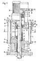
- a lower lantern part 7 is fastened by means of a flange 25 on a connecting flange 15 to be placed tightly on the opening of a pressure vessel.
- An upper lantern part, a " lifting lantern” 1 with a centering collar 6 engages in it in an axially displaceable manner.
- An upper flange 24 of the upper lantern part 1 carries a drive electric motor 19 and any gear 49 for driving a stirrer shaft 2 via an elastic coupling 16.
- the stirrer shaft 2 is mounted in the upper lantern part 1 at its rear end in a fixed bearing 13 and in one Distance therefrom in a floating bearing 14. When lifting and lowering the upper lantern part 1 with respect to the lower lantern part 7, the agitator shaft 2 is taken along via the fixed bearing 13.
- an annular space 20 is formed between the cylindrical cavity receiving the collar 6 of the upper lantern part and the stirring shaft 2, in which packing rings 5 are accommodated.
- packing rings 5 There are two layers of such packing rings, between which a lubrication ring 17 is arranged.
- the packing rings rest on a base ring 9, under which a collar 8 arranged on the agitator shaft 2 engages.
- the lower packing rings and the base ring are received by a sleeve 18 with which the lower Part of the lower lantern part 7 to protect it against originating from the kettle contents chemical stresses annually stresses annually, glat- t he t; the sleeve 18 can consist of metal or ceramic materials or can be rubberized.
- a hydraulic cylinder 3 is fastened in the upper flange 22 of the lower lantern part 7, the piston 21 of which engages the upper flange 24 of the upper lantern part 1.
- a double-acting hydraulic cylinder is required, which has screw connections 10 and 11 for connecting pressure oil hoses.
- the cylinder can be operated by means of a hydraulic hand pump, such as is used in workshops, for example, for removing or mounting roller bearings. ,
- Guide bolts 4 are also fastened in the upper flange 22 of the lower lantern part 7 and pass through guide bushes 12 which are provided in the lower flange 23 and in the upper flange 24 of the upper lantern part 1.
- the packing rings are subject to considerable wear due to temperature influences and, depending on the contents to be stirred, also due to chemical influences, so that they are often retightened or need to be renewed; they are occasionally even in a charred state, so that the automatic pushing out of these elements from the otherwise receiving annular space is a particular relief until they are freely accessible.
- the diameter of the connecting flange 15 can be small in relation to the height of the agitator, but on the other hand it can be chosen at will to suit the pressure vessel on which the agitator is to be placed. Without this changing the way the sealing elements are lifted, the drive of the agitator shaft 2 carried by the flange 24 of the upper lantern part 1 can undergo numerous modifications.
- the lifting lantern 1 In its lower position, the lifting lantern 1 is appropriately secured both against unintentional lifting, which could inadvertently interrupt the operating state of the seal, and against unintentional lowering from its raised position. Because hydraulic cylinders are used as an auxiliary drive for the lifting lantern, they can be secured by an electrical control of the control valves of the hydraulic cylinders; However, mechanical securing in the form of a clamp 41, which can be fitted between the flanges 23 and 55 of the lifting lantern 1 on the guide pin 4, has proven to be particularly simple and reliable. In its raised and lowered position, the lifting lantern, as shown in FIG. 1, can be mechanically secured very simply by pushing the clamp in the axial direction up or down against the surface of the flanges 23 or 55 and tightening it with a knob 40.
- a lower lantern part 7 is fastened by means of a flange 25 on a connecting flange 15 to be placed tightly on the opening of a pressure vessel.
- a centering collar 6 of an upper, movable lantern part, namely the lifting lantern 1 engages in it.
- the lifting lantern 1 has a lower flange 23 and an upper flange 24.
- the upper flange carries a drive electric motor 19 which drives the agitator shaft via a gear 49 and an elastic coupling 16.
- the agitator shaft 2 of the example according to FIGS. 1-3 is divided in the example according to FIG. 4.
- the upper shaft part 2 ' is not flanged directly to the agitator shaft 2, but via a flange sleeve 30 surrounding the agitator shaft 2, at the upper end of which the flange 34 is located.
- the upper shaft part 2 ' has at its lower end a bell-shaped extension 43 3 , in which a stepped end pin 44 of the agitator shaft 2 is inserted with the interposition of a feather key 42. The drive torque is transmitted from the upper shaft part 2 'to the agitator shaft 2 via this key.
- a cage 27 is screwed with screws 46, which combines the mechanical seal parts to form a unit 26.
- the mechanical seal parts sit on the flange sleeve 30.
- the cylindrical annular space 20 formed in the lower, fixed lantern part 7 receives the cage 27 with the mechanical seal unit 26; the lower stationary lantern part 7 is thus also a mechanical seal housing.
- a pipe section 38 is shrunk in concentrically with the geometric axis of the agitator shaft. In this way, a labyrinth seal is formed, which prevents leakage from occurring.
- a hydraulic cylinder 3 is fastened in the upper flange 22 of the lower, fixed lantern part 7, the piston 21 of which acts on the upper flange 24 of the lifting lantern 1.
- a double-acting hydraulic cylinder is again required, which e.g. Has formed as screw connections line connection couplings 10 and 11 for connecting pressure oil hoses.
- guide bolts 4 are fastened, which pass through guide bushes 12 attached in the lower flange 23 and in the upper flange 24 of the lifting lantern 1.
- the lifting lantern 1 can be raised by means of the hydraulic cylinder 3 without the connection between the flanges 34 and 45 having to be released.
- the lifting lantern 1 is raised, the cage 27 of the mechanical seal 26 screwed onto its centering collar 6 is taken along, as is the flange sleeve 30, until the parts have reached the position shown on the right in FIG. 4. If the screws 46 are loosened in this position, the old mechanical seal parts can be easily removed downwards and through Replace new parts to be inserted above.
- Sealing rings 48 are arranged in the inner jacket of the flange sleeve 30 and seal the flange sleeve in relation to the agitator shaft 2 in the operating position.
- the lifting lantern is expediently mechanically secured in the lowered or raised position by means of a toggle 40 and a clamp 41, as was described for the example according to FIGS. 1-3; the hydraulic cylinder then does not necessarily have to remain under pressure for the duration of the seal replacement.
- the hydraulic cylinders 3 and the guide pins 4 are subsequently attached to an agitator of a known type in which the lamp 5 0 a transmission carries 49 to the housing of a motor is flange 19 from below.
- the hydraulic cylinders 3 are fastened on a mounting flange 52.
- the transmission output shaft and the upper part 2 'of the agitator shaft are detachably connected to one another by a rigid coupling 54.
- the housing of a commercially available mechanical seal 51 has an upper flange 56.
- the reciprocating pistons of the hydraulic cylinders 3 engage here on the bottom of the housing of the transmission 49; instead, they could act on brackets rigidly connected to the lantern 50 if they cannot be housed within the lantern 50.
- the guide bolts 4, also fastened on the mounting flange 52, are guided in flanges 23 and 55 of the lantern 50; the flange 55 contains a guide bush for the bolt 4.
- the lantern 50 After the lantern 50 has been released from the boiler-fixed parts, it is raised by means of the hydraulic cylinders 3 into the position shown in FIG. 6 without loosening the rigid coupling 54 with the upper agitator shaft part 2 'which represents an intermediate piece.
- the housing of the mechanical seal 51 was previously by means of its flange 56, as is provided on many commercially available mechanical seals, and one Rigid connection elements containing removal aid 53 connected to the shaft part 2 '. Therefore, it is peeled off when starting up the L aterne the mechanical seal from the shaft stub 44th In the raised position, the removal and W iederein tract of the mechanical seal or its wear subset easily possible, as described by analogy to the example according to Fig. 4.
- the optional gear 49 can be omitted entirely in exceptional cases, so that the motor 19 then drives the agitator shaft directly via the elastic coupling 16.
- the overall arrangement can then be made particularly slim, without being interrupted in its upper part by a gear housing projecting beyond the circumference of the motor housing.
Landscapes
- Chemical & Material Sciences (AREA)
- Chemical Kinetics & Catalysis (AREA)
- Accessories For Mixers (AREA)
- Sealing Of Bearings (AREA)
- Sealing Devices (AREA)
- Mixers Of The Rotary Stirring Type (AREA)
- Mechanical Sealing (AREA)
Applications Claiming Priority (2)
| Application Number | Priority Date | Filing Date | Title |
|---|---|---|---|
| DE2946126 | 1979-11-15 | ||
| DE2946126A DE2946126C2 (de) | 1979-11-15 | 1979-11-15 | Ruhrwerk |
Publications (1)
| Publication Number | Publication Date |
|---|---|
| EP0029476A1 true EP0029476A1 (de) | 1981-06-03 |
Family
ID=6086059
Family Applications (1)
| Application Number | Title | Priority Date | Filing Date |
|---|---|---|---|
| EP80100216A Withdrawn EP0029476A1 (de) | 1979-11-15 | 1980-01-17 | Rührwerk |
Country Status (6)
| Country | Link |
|---|---|
| US (1) | US4383768A (OSRAM) |
| EP (1) | EP0029476A1 (OSRAM) |
| JP (1) | JPS6013734B2 (OSRAM) |
| DD (1) | DD150005A5 (OSRAM) |
| DE (1) | DE2946126C2 (OSRAM) |
| IN (1) | IN150637B (OSRAM) |
Cited By (2)
| Publication number | Priority date | Publication date | Assignee | Title |
|---|---|---|---|---|
| EP0492360A1 (en) * | 1990-12-26 | 1992-07-01 | General Signal Corporation | Mixer apparatus for high horsepower mixer applications where mixer components of large weight and size are supported |
| WO2014184434A3 (en) * | 2013-05-13 | 2015-03-05 | Outotec (Finland) Oy | A drive supporting structure and a drive support element |
Families Citing this family (20)
| Publication number | Priority date | Publication date | Assignee | Title |
|---|---|---|---|---|
| CH542699A (de) * | 1972-02-18 | 1973-10-15 | P Huerlimann Hans | Vorrichtung zum Behandeln von Stoffen |
| EP0111148A3 (de) * | 1982-11-26 | 1986-07-16 | Dipl.-Ing. H. List Industrielle Verfahrenstechnik | Rührapparat mit schlagempfindlicher Schutzschicht |
| US4535836A (en) * | 1983-10-18 | 1985-08-20 | Crepaco, Inc. | Vertically extending heat exchanger |
| US4556222A (en) * | 1984-10-29 | 1985-12-03 | Lewis Donald E | Auxiliary sealing system for fluid mixers |
| DE3512257A1 (de) * | 1985-04-03 | 1986-10-09 | Herfeld, Friedrich Walter, Dr., 5982 Neuenrade | Mischvorrichtung |
| JPS63293828A (ja) * | 1987-05-26 | 1988-11-30 | Nec Kyushu Ltd | 半導体基板処理装置 |
| US4753534A (en) * | 1987-05-28 | 1988-06-28 | General Signal Corp. | Mixing apparatus |
| FI90732C (fi) * | 1989-05-09 | 1994-03-25 | Ahlstroem Oy | Sekoitin |
| US5094542A (en) * | 1990-11-19 | 1992-03-10 | General Signal Corporation | Modular mixer system |
| DE4127873C2 (de) * | 1991-08-22 | 1995-02-23 | Reimelt Dietrich Kg | Kneteinrichtung für eine zu knetende Masse |
| EP0935718A4 (en) * | 1996-11-07 | 2001-03-14 | Gen Signal Corp | Transmission assembly |
| US5720486A (en) * | 1996-11-07 | 1998-02-24 | General Signal Corporation | Self-formed labyrinth seal |
| US6193409B1 (en) * | 1999-06-10 | 2001-02-27 | Paul Mueller Company | Tank agitator having a clean-in-place shaft and seal assembly |
| US20020181325A1 (en) * | 2001-06-05 | 2002-12-05 | Engel David J | Mixer seal and bearing apparatus and method |
| US8899594B2 (en) | 2012-12-21 | 2014-12-02 | Mcnish Corporation | Adjustable seal apparatus for mounting a mixing apparatus to a vessel |
| EP2990101B1 (fr) * | 2014-08-29 | 2019-09-11 | Milton Roy Europe | Systeme de démontage de l'étanchéité d'une rotule |
| CN112808056A (zh) * | 2021-02-01 | 2021-05-18 | 王峰 | 一种搅拌装置、反应容器以及分析仪器 |
| CN114453923B (zh) * | 2022-02-16 | 2022-07-29 | 冈田精机丹阳有限公司 | 一种凸轮和油压复合驱动的双交换数控转台 |
| CN117248413A (zh) * | 2023-08-24 | 2023-12-19 | 无锡泰特筑路机械有限公司 | 一种泡沫沥青温拌装置 |
| CN117165407A (zh) * | 2023-09-13 | 2023-12-05 | 广东碳源生物科技有限公司 | 一种具有可拆卸搅拌轴的发酵设备 |
Citations (8)
| Publication number | Priority date | Publication date | Assignee | Title |
|---|---|---|---|---|
| DE1226987B (de) * | 1961-05-23 | 1966-10-20 | Werner Winckelhaus | Ruehrwerksantrieb |
| CH467097A (de) * | 1967-02-24 | 1969-01-15 | Gerhard Kestermann Zahnraeder | Rührwerksantrieb |
| DE1809018A1 (de) * | 1968-11-15 | 1970-12-03 | Dieter Kupka | Ruehrwerk |
| DE2004392A1 (en) * | 1970-01-31 | 1971-08-12 | Kupka D | Agitator shaft seal changeable withoutdepressurising vessel |
| DE1632458A1 (de) * | 1968-01-09 | 1973-07-05 | Dieter Kupka | Ruehrwerk |
| DE1782266B1 (de) * | 1968-08-07 | 1974-05-30 | Dieter Kupka | Ruehrwerksantrieb |
| DE1750468B1 (de) * | 1968-05-04 | 1974-06-20 | Dieter Kupka | Ruehrwerksantrieb |
| GB2009839A (en) * | 1977-12-08 | 1979-06-20 | Westinghouse Electric Corp | Motor jacking apparatus |
Family Cites Families (3)
| Publication number | Priority date | Publication date | Assignee | Title |
|---|---|---|---|---|
| US2638364A (en) * | 1950-09-29 | 1953-05-12 | J H Day Company Inc | Stuffing box for dough mixers |
| DE1557104B2 (de) * | 1966-11-19 | 1970-06-18 | Gerhard Kestermann Zahnraeder | Ruehrwerksantrieb |
| DE2363237A1 (de) * | 1973-12-19 | 1975-06-26 | Von Roll Ag | Staender fuer die lagerung der ruehrerwelle eines ruehrbehaelters |
-
1979
- 1979-11-15 DE DE2946126A patent/DE2946126C2/de not_active Expired
-
1980
- 1980-01-17 EP EP80100216A patent/EP0029476A1/de not_active Withdrawn
- 1980-03-19 IN IN314/CAL/80A patent/IN150637B/en unknown
- 1980-04-09 DD DD80220304A patent/DD150005A5/de unknown
- 1980-05-01 JP JP55057165A patent/JPS6013734B2/ja not_active Expired
-
1982
- 1982-04-30 US US06/373,641 patent/US4383768A/en not_active Expired - Fee Related
Patent Citations (8)
| Publication number | Priority date | Publication date | Assignee | Title |
|---|---|---|---|---|
| DE1226987B (de) * | 1961-05-23 | 1966-10-20 | Werner Winckelhaus | Ruehrwerksantrieb |
| CH467097A (de) * | 1967-02-24 | 1969-01-15 | Gerhard Kestermann Zahnraeder | Rührwerksantrieb |
| DE1632458A1 (de) * | 1968-01-09 | 1973-07-05 | Dieter Kupka | Ruehrwerk |
| DE1750468B1 (de) * | 1968-05-04 | 1974-06-20 | Dieter Kupka | Ruehrwerksantrieb |
| DE1782266B1 (de) * | 1968-08-07 | 1974-05-30 | Dieter Kupka | Ruehrwerksantrieb |
| DE1809018A1 (de) * | 1968-11-15 | 1970-12-03 | Dieter Kupka | Ruehrwerk |
| DE2004392A1 (en) * | 1970-01-31 | 1971-08-12 | Kupka D | Agitator shaft seal changeable withoutdepressurising vessel |
| GB2009839A (en) * | 1977-12-08 | 1979-06-20 | Westinghouse Electric Corp | Motor jacking apparatus |
Cited By (2)
| Publication number | Priority date | Publication date | Assignee | Title |
|---|---|---|---|---|
| EP0492360A1 (en) * | 1990-12-26 | 1992-07-01 | General Signal Corporation | Mixer apparatus for high horsepower mixer applications where mixer components of large weight and size are supported |
| WO2014184434A3 (en) * | 2013-05-13 | 2015-03-05 | Outotec (Finland) Oy | A drive supporting structure and a drive support element |
Also Published As
| Publication number | Publication date |
|---|---|
| IN150637B (OSRAM) | 1982-11-20 |
| DD150005A5 (de) | 1981-08-12 |
| DE2946126A1 (de) | 1981-05-21 |
| DE2946126C2 (de) | 1986-08-14 |
| US4383768A (en) | 1983-05-17 |
| JPS6013734B2 (ja) | 1985-04-09 |
| JPS5670825A (en) | 1981-06-13 |
Similar Documents
| Publication | Publication Date | Title |
|---|---|---|
| EP0029476A1 (de) | Rührwerk | |
| DE2924234C2 (de) | Hydraulische Ausrückvorrichtung für eine Fahrzeug-Schaltkupplung | |
| DE2754736A1 (de) | Vorrichtung zur anbringung von endverschlusselementen an eine folge von behaelterruempfen | |
| DE2428819C3 (de) | Konverter | |
| DE1750468B1 (de) | Ruehrwerksantrieb | |
| DE60213368T2 (de) | Werkzeugmaschine mit hauptwellenausgleichsvorrichtung | |
| DE4106094A1 (de) | Ruehrwerksnutschenfilter | |
| DE2035698A1 (en) | Roll neck bearings - changed rapidly using a bayonet-type connection | |
| DE2604010A1 (de) | Hydraulische antriebseinrichtung fuer eine spanneinrichtung einer waelzfraesmaschine | |
| DE2535984C2 (de) | Vorrichtung zum Auswechseln eines Dichtkörpers eines Rührwerks | |
| DE68908977T2 (de) | Schaftlagervorrichtung. | |
| EP0213214B1 (de) | Rührwerk | |
| DE927951C (de) | Aufzug fuer Fahrzeuge od. dgl. | |
| DE7932268U1 (de) | Ruehrwerk | |
| DE1226987B (de) | Ruehrwerksantrieb | |
| DE1525492C (de) | Dichtungsanordnung | |
| DE3151554C2 (de) | Schmiervorrichtung für Getriebelager | |
| DE102021121654B3 (de) | Pumpenvorrichtung, Verfahren zur Durchführung eines Service bei einer Pumpenvorrichtung | |
| AT391095B (de) | Ruehrwerksgetriebe | |
| EP0268786B1 (de) | Verschluss für eine hydraulische Kolben-Zylinder-Einheit | |
| DE2004392B2 (de) | Rührwerkantrieb | |
| DE2418149B2 (de) | Feststellvorrichtung für Eintauchpumpen | |
| EP0412319B1 (de) | Behälterrührwerk mit lösbarer Kupplung | |
| DE3409464C2 (de) | Vorrichtung für Dichtungsteile einer aus einem Gehäuse austretenden, drehbaren Welle | |
| DE4028306A1 (de) | Ruehrwerk mit einrichtung zum dichtungsschnellwechsel |
Legal Events
| Date | Code | Title | Description |
|---|---|---|---|
| PUAI | Public reference made under article 153(3) epc to a published international application that has entered the european phase |
Free format text: ORIGINAL CODE: 0009012 |
|
| AK | Designated contracting states |
Designated state(s): AT CH FR GB NL |
|
| 17P | Request for examination filed |
Effective date: 19810514 |
|
| STAA | Information on the status of an ep patent application or granted ep patent |
Free format text: STATUS: THE APPLICATION IS DEEMED TO BE WITHDRAWN |
|
| 18D | Application deemed to be withdrawn |
Effective date: 19840229 |