WO2023276577A1 - 電池測定装置及び電池測定方法 - Google Patents
電池測定装置及び電池測定方法 Download PDFInfo
- Publication number
- WO2023276577A1 WO2023276577A1 PCT/JP2022/022905 JP2022022905W WO2023276577A1 WO 2023276577 A1 WO2023276577 A1 WO 2023276577A1 JP 2022022905 W JP2022022905 W JP 2022022905W WO 2023276577 A1 WO2023276577 A1 WO 2023276577A1
- Authority
- WO
- WIPO (PCT)
- Prior art keywords
- signal
- complex impedance
- electrical path
- battery
- abnormality
- Prior art date
- Legal status (The legal status is an assumption and is not a legal conclusion. Google has not performed a legal analysis and makes no representation as to the accuracy of the status listed.)
- Ceased
Links
Images


Classifications
-
- G—PHYSICS
- G01—MEASURING; TESTING
- G01R—MEASURING ELECTRIC VARIABLES; MEASURING MAGNETIC VARIABLES
- G01R31/00—Arrangements for testing electric properties; Arrangements for locating electric faults; Arrangements for electrical testing characterised by what is being tested not provided for elsewhere
- G01R31/36—Arrangements for testing, measuring or monitoring the electrical condition of accumulators or electric batteries, e.g. capacity or state of charge [SoC]
- G01R31/389—Measuring internal impedance, internal conductance or related variables
-
- G—PHYSICS
- G01—MEASURING; TESTING
- G01R—MEASURING ELECTRIC VARIABLES; MEASURING MAGNETIC VARIABLES
- G01R31/00—Arrangements for testing electric properties; Arrangements for locating electric faults; Arrangements for electrical testing characterised by what is being tested not provided for elsewhere
- G01R31/36—Arrangements for testing, measuring or monitoring the electrical condition of accumulators or electric batteries, e.g. capacity or state of charge [SoC]
- G01R31/382—Arrangements for monitoring battery or accumulator variables, e.g. SoC
- G01R31/3842—Arrangements for monitoring battery or accumulator variables, e.g. SoC combining voltage and current measurements
-
- G—PHYSICS
- G01—MEASURING; TESTING
- G01R—MEASURING ELECTRIC VARIABLES; MEASURING MAGNETIC VARIABLES
- G01R35/00—Testing or calibrating of apparatus covered by the other groups of this subclass
-
- H—ELECTRICITY
- H01—ELECTRIC ELEMENTS
- H01M—PROCESSES OR MEANS, e.g. BATTERIES, FOR THE DIRECT CONVERSION OF CHEMICAL ENERGY INTO ELECTRICAL ENERGY
- H01M10/00—Secondary cells; Manufacture thereof
- H01M10/42—Methods or arrangements for servicing or maintenance of secondary cells or secondary half-cells
- H01M10/48—Accumulators combined with arrangements for measuring, testing or indicating the condition of cells, e.g. the level or density of the electrolyte
-
- G—PHYSICS
- G01—MEASURING; TESTING
- G01R—MEASURING ELECTRIC VARIABLES; MEASURING MAGNETIC VARIABLES
- G01R31/00—Arrangements for testing electric properties; Arrangements for locating electric faults; Arrangements for electrical testing characterised by what is being tested not provided for elsewhere
- G01R31/36—Arrangements for testing, measuring or monitoring the electrical condition of accumulators or electric batteries, e.g. capacity or state of charge [SoC]
- G01R31/392—Determining battery ageing or deterioration, e.g. state of health
-
- G—PHYSICS
- G01—MEASURING; TESTING
- G01R—MEASURING ELECTRIC VARIABLES; MEASURING MAGNETIC VARIABLES
- G01R31/00—Arrangements for testing electric properties; Arrangements for locating electric faults; Arrangements for electrical testing characterised by what is being tested not provided for elsewhere
- G01R31/36—Arrangements for testing, measuring or monitoring the electrical condition of accumulators or electric batteries, e.g. capacity or state of charge [SoC]
- G01R31/396—Acquisition or processing of data for testing or for monitoring individual cells or groups of cells within a battery
-
- G—PHYSICS
- G01—MEASURING; TESTING
- G01R—MEASURING ELECTRIC VARIABLES; MEASURING MAGNETIC VARIABLES
- G01R31/00—Arrangements for testing electric properties; Arrangements for locating electric faults; Arrangements for electrical testing characterised by what is being tested not provided for elsewhere
- G01R31/50—Testing of electric apparatus, lines, cables or components for short-circuits, continuity, leakage current or incorrect line connections
- G01R31/54—Testing for continuity
-
- Y—GENERAL TAGGING OF NEW TECHNOLOGICAL DEVELOPMENTS; GENERAL TAGGING OF CROSS-SECTIONAL TECHNOLOGIES SPANNING OVER SEVERAL SECTIONS OF THE IPC; TECHNICAL SUBJECTS COVERED BY FORMER USPC CROSS-REFERENCE ART COLLECTIONS [XRACs] AND DIGESTS
- Y02—TECHNOLOGIES OR APPLICATIONS FOR MITIGATION OR ADAPTATION AGAINST CLIMATE CHANGE
- Y02E—REDUCTION OF GREENHOUSE GAS [GHG] EMISSIONS, RELATED TO ENERGY GENERATION, TRANSMISSION OR DISTRIBUTION
- Y02E60/00—Enabling technologies; Technologies with a potential or indirect contribution to GHG emissions mitigation
- Y02E60/10—Energy storage using batteries
Definitions
- the present disclosure relates to a battery measuring device and a battery measuring method.
- Patent Document 1 it is determined whether or not there is an abnormality in the detection line based on the difference in voltage detection when the short-circuit switches corresponding to adjacent battery cells are controlled to turn on and off. As a result, in addition to disconnection of the detection line, defects such as an increase in the wiring resistance of the detection line due to poor connection or the like can be appropriately detected as abnormalities in the detection line.
- the detection line is usually wired on the circuit board, and on the detection line between the battery monitoring circuit and the battery cell, there are harnesses and connectors for connecting the battery cell and the detection line, fuses, Elements such as beads, filter circuits, etc. are typically provided. Therefore, when the short-circuit switch is turned on and off, the voltage drops temporarily due to the magnitude of these resistances and the influence of the filter circuit, degrading the detection accuracy of the measured voltage. Therefore, when the short-circuit switch is turned on and off, it is necessary to wait until the voltage is restored before measuring the voltage. Therefore, when it is necessary to measure the voltage frequently, there is a problem that the time for turning on and off the short-circuiting switch cannot be secured.
- the present disclosure has been made in view of the above problems, and an object thereof is to provide a battery measuring device and a battery measuring method capable of detecting an abnormality and a sign of an abnormality while suppressing deterioration of measurement accuracy. It is in.
- a battery measuring device for measuring the state of a storage battery that solves the above problems is provided on a first electrical path connecting a positive electrode and a negative electrode of the storage battery, and outputs a predetermined AC signal from the storage battery, or and a signal control unit for inputting a predetermined AC signal to and a second electrical path connecting between the positive electrode and the negative electrode, through the second electrical path, voltage fluctuation of the storage battery with respect to the AC signal a voltage measurement unit for inputting a voltage change, a calculation unit for calculating information on the complex impedance based on the voltage fluctuation, and a determination unit for determining an abnormality and a sign of an abnormality in the second electrical path based on the information on the complex impedance. And prepare.
- a battery measuring method for solving the above problems is implemented by a battery measuring device for measuring the state of a storage battery, and utilizes a signal control section provided on a first electrical path connecting the positive electrode and the negative electrode of the storage battery. a signal control step of outputting a predetermined AC signal from the storage battery or inputting a predetermined AC signal to the storage battery; and a voltage measuring unit provided on a second electrical path connecting the positive electrode and the negative electrode.
- a voltage acquisition step of acquiring voltage fluctuations of the storage battery with respect to the AC signal via the second electrical path a calculation step of calculating information about a complex impedance based on the voltage fluctuations, and the complex and a determining step of determining an abnormality and a sign of an abnormality in the second electrical path based on the information about the impedance.
- the voltage of the storage battery fluctuates according to the AC signal, and information about the complex impedance can be calculated based on the voltage fluctuation.
- This complex impedance not only reflects the state of the accumulator, but also the state of the second electrical path. Therefore, it is possible to determine the abnormality of the second electrical path and its sign from the information on the complex impedance.
- the voltage fluctuation is measured in the second electrical path, only a minute current flows compared to the current flowing in the first electrical path. In other words, even if the current in the first electrical path is stopped, the resulting voltage fluctuation is very small. Therefore, when measuring the voltage of the storage battery using the voltage measuring unit, even if the AC signal on the first electric path is stopped, the degree of voltage drop is small. Therefore, even if the voltage is acquired at arbitrary timing, it is possible to suppress the deterioration of the voltage measurement accuracy. Alternatively, the waiting time until the voltage becomes normal can be shortened.
- FIG. 1 is a schematic configuration diagram of a power supply system
- FIG. 2 is a block diagram showing the configuration of the battery measuring device
- FIG. 3 is a schematic diagram showing a connection mode between the battery measuring device and the battery cell
- FIG. 4 is a flowchart of impedance calculation processing
- 5, (a) is a diagram showing the real part and the imaginary part of the complex impedance when the connection is poor
- (b) is a diagram showing the real part and the imaginary part of the complex impedance when the connection is good
- FIG. 1 is a schematic configuration diagram of a power supply system
- FIG. 2 is a block diagram showing the configuration of the battery measuring device
- FIG. 3 is a schematic diagram showing a connection mode between the battery measuring device and the battery cell
- FIG. 4 is a flowchart of impedance calculation processing
- 5 is a diagram showing the real part and the imaginary part of the complex impedance when the connection is poor
- (b) is a diagram showing the real part and the imaginary part of the complex im
- FIG. 6 is a flowchart of abnormality determination processing
- 7 (a) is a diagram showing the real part of the complex impedance at the time of poor connection
- (b) is a diagram showing the real part of the complex impedance at the time of disconnection
- (c) is a diagram showing the real part of the complex impedance at the time of abnormality of the battery cell.
- FIG. 4 is a diagram showing the real part of the complex impedance
- FIG. 8 is a schematic diagram showing a connection mode between a battery measuring device and a battery cell in another example
- FIG. 9 is a schematic diagram showing a connection mode between a battery measuring device and a battery cell in another example
- FIG. 10 is a schematic diagram showing a connection mode between a battery measuring device and a battery cell in another example.
- a power supply system 10 includes a motor 20 as a rotating electrical machine, an inverter 30 as a power converter that supplies a three-phase current to the motor 20, a rechargeable battery 40, and a rechargeable battery 40. 40, and an ECU 60 for controlling the motor 20 and the like.
- the motor 20 is the vehicle's main engine, and can transmit power to drive wheels (not shown).
- a three-phase permanent magnet synchronous motor is used as the motor 20 .
- the inverter 30 is composed of a full bridge circuit having the same number of upper and lower arms as the number of phases of the phase windings, and by turning on and off the switches (semiconductor switching elements) provided in each arm, current flows in each phase winding. adjusted.
- the inverter 30 is provided with an inverter control device (not shown), and the inverter control device controls energization by turning on and off each switch in the inverter 30 based on various detection information in the motor 20 and requests for power running and power generation. to implement.
- the inverter control device supplies electric power from the assembled battery 40 to the motor 20 via the inverter 30 to drive the motor 20 in power running mode.
- the inverter control device causes the motor 20 to generate power based on the power from the drive wheels, converts the generated power via the inverter 30 and supplies it to the assembled battery 40 to charge the assembled battery 40 .
- the assembled battery 40 is electrically connected to the motor 20 via the inverter 30 .
- the assembled battery 40 has a terminal voltage of, for example, 100 V or more, and is configured by connecting a plurality of battery modules 41 in series.
- the battery module 41 is configured by connecting a plurality of battery cells 42 in series.
- As the battery cell 42 for example, a lithium ion storage battery or a nickel metal hydride storage battery can be used.
- Each battery cell 42 is a storage battery having an electrolyte and a plurality of electrodes.
- a positive terminal of an electrical load such as an inverter 30 is connected to a positive power supply path L1 connected to a positive power supply terminal of the assembled battery 40 .
- a negative terminal of an electrical load such as the inverter 30 is connected to the negative power supply path L2 connected to the negative power supply terminal of the assembled battery 40 .
- a relay switch SMR system main relay switch
- the battery measuring device 50 is a device that measures the state of charge (SOC) and the state of deterioration (SOH) of each battery cell 42 .
- the battery measuring device 50 is connected to the ECU 60 and outputs the state of each battery cell 42 and the like. The configuration of the battery measuring device 50 will be described later.
- the ECU 60 requests the inverter control device for power running and power generation based on various information.
- the various information includes, for example, accelerator and brake operation information, vehicle speed, the state of the assembled battery 40, and the like.
- a battery measuring device 50 As shown in FIG. 2, in the first embodiment, a battery measuring device 50 is provided so that the state of each battery cell 42 can be measured and monitored.
- the battery measuring device 50 includes an ASIC section 50a, a filter section 55, and a current modulation circuit 56.
- the ASIC unit 50 a includes a stabilized power supply unit 51 , an input/output unit 52 , a microcomputer unit 53 as a calculation unit, and a communication unit 54 .
- the stabilized power supply unit 51 is connected to the power supply line of the battery cell 42 and supplies the power supplied from the battery cell 42 to the input/output unit 52, the microcomputer unit 53, and the communication unit 54.
- the input/output unit 52, the microcomputer unit 53, and the communication unit 54 are driven based on this electric power.
- the input/output unit 52 is connected to the battery cell 42 to be measured. Specifically, the input/output unit 52 has a DC voltage input terminal 57 capable of inputting (measuring) a DC voltage from the battery cell 42 .
- the DC voltage input terminal 57 is connected to the battery cell 42 via a third electrical path 83 for voltage detection.
- a filter section 55 is provided in the third electrical path 83 between the battery cell 42 and the DC voltage input terminal 57 . That is, between the positive terminal 57a and the negative terminal 57b of the DC voltage input terminal 57, an RC filter 55a as a filter circuit and a Zener diode 55b as a protective element are provided. In other words, the RC filter 55a, the Zener diode 55b, and the like are connected in parallel to the battery cell 42 .
- the input/output unit 52 also has a response signal input terminal 58 for inputting a response signal (voltage fluctuation) reflecting the internal complex impedance information of the battery cell 42 between terminals of the battery cell 42 .
- the response signal input terminal 58 is connected to the battery cell 42 via a second electrical path 82 as shown in FIG. That is, the positive terminal of the response signal input terminal 58 is connected to the positive power supply terminal 71a of the battery cell 42 via the second electrical path 82, and the negative terminal of the response signal input terminal 58 is connected to the second electrical path 82. is connected to the negative electrode side power supply terminal 71b of the battery cell 42 via the .
- the second electrical path 82 and the third electrical path 83 are provided independently, but they may share some or all of them.
- the input/output unit 52 functions as a voltage measurement unit.
- the positive electrode side power terminal 71a and the negative electrode side power terminal 71b of the battery cell 42 are each connected to an electrode (positive electrode or negative electrode).
- the response signal input terminal 58 is desirably connected to a portion closest to the electrodes among the connectable portions of the positive power terminal 71a and the negative power terminal 71b.
- the connecting point of the DC voltage input terminal 57 is preferably the point closest to the electrode or the next closest point after the connecting point of the response signal input terminal 58 . This minimizes the effect of voltage drop due to main current or equalization current.
- the input/output unit 52 is connected to a current modulation circuit 56 as a signal control unit, and outputs an instruction signal to the current modulation circuit 56 to instruct a sine wave signal (AC signal) to be output from the battery cell 42. It has an instruction signal output terminal 59a for output.
- the input/output unit 52 also has a feedback signal input terminal 59b.
- the feedback signal input terminal 59b receives the alternating current actually output from the battery cell 42 (flowing through the first electrical path 81) via the current modulation circuit 56 as a feedback signal (measured alternating current, that is, the measured value). ).
- the input/output unit 52 is connected to the microcomputer unit 53, and includes a DC voltage input from the DC voltage input terminal 57, a response signal input from the response signal input terminal 58, and a feedback signal input from the feedback signal input terminal 59b. etc. to the microcomputer unit 53 .
- the input/output unit 52 has an AD converter inside and is configured to convert an input analog signal into a digital signal and output the digital signal to the microcomputer unit 53 .
- the input/output unit 52 is configured to input an instruction signal from the microcomputer unit 53, and is configured to output the instruction signal to the current modulation circuit 56 from the instruction signal output terminal 59a.
- the input/output unit 52 has a DA converter inside, converts a digital signal input from the microcomputer unit 53 into an analog signal, and outputs an instruction signal to the current modulation circuit 56.
- the AC signal (sine wave signal) instructed by the instruction signal to the current modulation circuit 56 is DC biased so that the sine wave signal does not become a negative current (backflow to the battery cell 42). It's becoming
- the current modulation circuit 56 is a circuit that outputs a predetermined AC signal (sine wave signal) using the battery cell 42 to be measured as a power source. As shown in FIG. 3, the current modulation circuit 56 is arranged on the first electrical path 81 connecting the positive power terminal 71a and the negative power terminal 71b of the battery cell 42. As shown in FIG. In this embodiment, the first electrical path 81 and the second electrical path 82 are provided independently.
- the current modulation circuit 56 includes a semiconductor switch element 56a (e.g., MOSFET) as a switch section, and a resistor 56b as a shunt resistor connected in series with the semiconductor switch element 56a.
- the drain terminal of the semiconductor switch element 56a is connected to the positive electrode side power terminal 71a of the battery cell 42 via the first electric path 81, and the source terminal of the semiconductor switch element 56a is connected in series to one end of the resistor 56b. .
- the other end of the resistor 56b is connected to the negative power terminal 71b of the battery cell 42 via the first electrical path 81.
- the semiconductor switch element 56a is configured to be able to adjust the amount of energization between the drain terminal and the source terminal.
- a resistor may be inserted in series in the current modulation circuit in order to adjust the voltage applied to the semiconductor switch element 56a.
- the current modulation circuit 56 is provided with a current detection amplifier 56c as a current measuring section connected to both ends of the resistor 56b.
- the current detection amplifier 56c detects an alternating current flowing through the resistor 56b (that is, an alternating current flowing through the first electrical path 81) and outputs the detection result to the feedback signal input terminal 59b of the input/output unit 52 as a feedback signal.
- the current modulation circuit 56 is provided with a feedback circuit 56d.
- the feedback circuit 56d is configured to receive the instruction signal from the instruction signal output terminal 59a of the input/output unit 52 and the feedback signal from the current detection amplifier 56c. Then, the instruction signal and the feedback signal are compared, and the result is output to the gate terminal of the semiconductor switch element 56a.
- the semiconductor switch element 56a Based on the signal from the feedback circuit 56d, the semiconductor switch element 56a applies a voltage between the gate and the source so that the battery cell 42 outputs a sine wave signal (predetermined AC signal) indicated by the instruction signal. Adjust to adjust the amount of current between drain and source. If there is an error between the waveform instructed by the instruction signal and the waveform actually flowing through the resistor 56b, the semiconductor switch element 56a corrects the error based on the signal from the feedback circuit 56d. Adjust the amount of current so that This stabilizes the AC signal (sine wave signal) flowing through the resistor 56b.
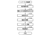
- the battery measuring device 50 executes the impedance calculation process shown in FIG. 4 at predetermined intervals.
- the microcomputer section 53 first sets the measurement frequency of the complex impedance (step S101).
- the measurement frequency is set from frequencies within a predetermined measurement range.
- Step S102 corresponds to the signal control step.
- the input/output unit 52 converts it into an analog signal by the DA converter and outputs it to the current modulation circuit 56 .
- the current modulation circuit 56 uses the battery cell 42 as a power source to output an AC signal.
- the semiconductor switch element 56a adjusts the amount of current so that the battery cell 42 outputs the AC signal indicated by the instruction signal. As a result, an AC signal is output from the battery cell 42 .
- the input/output unit 52 receives the voltage fluctuation through a response signal input terminal 58 and outputs it to the microcomputer unit 53 as a response signal. At that time, the signal is converted into a digital signal by an AD converter and output.
- the microcomputer unit 53 After executing step S102, the microcomputer unit 53 inputs a response signal from the input/output unit 52 (step S103). Further, the microcomputer unit 53 acquires the alternating current flowing through the resistor 56b of the current modulation circuit 56 as a feedback signal (step S104). Specifically, the microcomputer unit 53 inputs the feedback signal output from the current detection amplifier 56c via the input/output unit 52 . Note that instead of the feedback signal, a value proportional to the instruction signal instructing the current modulation circuit 56 may be acquired. Step S103 corresponds to the voltage acquisition step.
- the microcomputer unit 53 calculates information regarding the complex impedance of the battery cell 42 based on the response signal and the feedback signal (measured alternating current) (step S105).
- the microcomputer unit 53 calculates information about the complex impedance of the battery cell 42 by two-phase lock-in detection of the response signal using the feedback signal as a reference signal. That is, the microcomputer unit 53 calculates all of the real part, the imaginary part, the absolute value, and the phase of the complex impedance based on the real part of the response signal, the imaginary part of the response signal, the real part of the current signal, and the imaginary part of the current signal. Or calculate either.
- Step S105 corresponds to the calculation step.
- the microcomputer unit 53 outputs the calculation result to the ECU 60 via the communication unit 54 (step S106). Then, the calculation process ends.
- the ECU 60 creates, for example, a complex impedance plane plot (Cole-Cole plot) based on the calculation results, and grasps the characteristics of the electrodes, the electrolyte, and the like. For example, the state of charge (SOC) and the state of deterioration (SOH) are grasped.
- SOC state of charge
- SOH state of deterioration
- the complex impedance at a specific frequency is measured at regular time intervals, and changes in SOC, SOH, battery temperature, etc. during running may be grasped based on the time change of the complex impedance at the specific frequency.
- the complex impedance at a specific frequency may be measured at time intervals such as every day, every round, or every year, and changes in SOH or the like may be grasped based on the time change in the complex impedance at the specific frequency.
- the battery measuring device 50 is configured to be able to determine an abnormality in the battery cell 42 based on the calculated complex impedance, and is configured to be able to determine an abnormality and a sign of an abnormality in the second electrical path 82.
- the abnormality of the second electrical path 82 specifically means disconnection in the second electrical path 82 .
- Disconnection refers to a state in which the connection is completely cut off and electricity cannot be supplied. More specifically, in the middle of an electrical path, the conductor is cut off and is connected only by the insulating film that covers the conductor, or in the middle of the electrical path, the path is completely cut off and an insulating layer of air is created. This state is called disconnection. In terms of an equivalent circuit, it can be said that when the wire is disconnected, a large resistance is placed on the path by the insulating coating or the insulating layer made of air.
- a sign of an abnormality in the second electrical path 82 is a state of connection failure or wiring failure. In the following description, they may be collectively referred to as poor connection or the like.
- a connection failure or a wiring failure is a state in which the electrical path is about to be cut off even though electricity is supplied, and the resistance of the electrical path is increased or fluctuates more than usual.
- the second electrical path 82 has wiring impedances 82a and 82b and an inter-wiring impedance 82c.
- the wiring impedances 82a and 82b are obtained by synthesizing impedances based on various circuit elements arranged on wirings and paths.
- the inter-wiring impedance 82c is obtained by synthesizing the impedance based on the circuit elements arranged between the paths and the stray capacitance.
- the calculated complex impedance Z is It is affected not only by the internal complex impedance of the battery cell 42, but also by their wiring impedances 82a and 82b and inter-wiring impedance 82c.
- the wiring resistance in the second electrical path 82 generally increases, so that the wiring impedances 82a and 82b and the inter-wiring impedance 82c also change.
- FIG. 5(a) shows the real part (left figure) and imaginary part (right figure) of the complex impedance calculated when a connection failure or the like occurs.
- FIG. 5B shows the real part (left figure) and the imaginary part (right figure) of the complex impedance calculated when the connection and wiring are good.
- FIG. 5 shows measurements taken under the same conditions multiple times.
- the imaginary part of the complex impedance is a value related to the capacitive component of the path. Further, even if the resistance component increases due to poor connection or the like, the effect on the capacitance component is small (there is little change). Therefore, even if a connection failure or the like occurs, it is considered that the imaginary part of the complex impedance measured by applying an AC signal can be measured in substantially the same manner as long as the current is being supplied.
- this principle is used to determine an abnormality and a sign of an abnormality in the second electrical path 82 as described below.
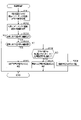
- Abnormality determination processing executed by the microcomputer unit 53 will be described with reference to FIG.
- the abnormality determination process is executed, for example, after the impedance calculation process.
- the microcomputer unit 53 acquires the real part and the imaginary part of the complex impedance at a specific frequency equal to or higher than the predetermined frequency f1 from the complex impedance calculated this time (step S201).
- the real part and the imaginary part obtained in step S201 may be referred to as current values.
- the microcomputer unit 53 acquires the real part and the imaginary part of the complex impedance at the specific frequency from the previously calculated complex impedance (step S202).
- the real part and the imaginary part acquired in step S202 may be referred to as previous values. It is desirable that the elapsed time from the previous calculation to the current calculation be a short time such that the measurement conditions including the state of the battery cell 42 (SOC, voltage, SOH, etc.) do not change. As long as it is determined that the measurement conditions are the same, there is no problem even if the elapsed time is long.
- the microcomputer unit 53 compares the real parts of the obtained complex impedances, and determines whether the difference between the current value and the previous value is equal to or greater than the first threshold (step S203). If the determination result is negative, the microcomputer unit 53 terminates the abnormality determination process.
- the first threshold is a threshold that indicates at least that a connection failure or the like has occurred, and is determined in advance by experiments or the like.
- step S204 the microcomputer unit 53 compares the imaginary parts of the acquired complex impedances, and determines whether the difference between the current value and the previous value is less than the second threshold (step S204).
- the second threshold is a threshold indicating that a disconnection or an abnormality has occurred in the battery cell 42, and is determined in advance by experiments or the like. If the determination result is affirmative, the microcomputer unit 53 determines that there is a possibility that poor connection or the like has occurred in the second electrical path 82 as a sign of abnormality in the second electrical path 82 (step S205). Then, the microcomputer unit 53 notifies the ECU 60 and the like that there is a possibility that a connection failure or the like has occurred in the second electric path 82, and terminates the abnormality determination process.
- step S204 determines that the current value of the real part of the complex impedance is greater than the previous value and that the difference is equal to or greater than the first threshold. It is determined whether or not the battery abnormality determination value is greater than or equal to (step S206). If the determination result is affirmative, the microcomputer unit 53 determines that there is a possibility that an abnormality has occurred in the battery cell 42 (step S207). Then, the microcomputer unit 53 notifies the ECU 60 and the like that there is a possibility that an abnormality has occurred in the battery cell 42, and terminates the abnormality determination process.
- step S208 the microcomputer section 53 determines that there is a possibility that the second electrical path 82 is disconnected. For example, when the current value of the real part of the complex impedance is smaller than the previous value by a first threshold value or more, the microcomputer 53 determines that there is a high possibility that the second electrical path 82 is disconnected. Then, the abnormality determination process ends.
- the microcomputer unit 53 has a function as a determination unit by executing abnormality determination processing. Further, steps S201 to S208 of the abnormality determination process correspond to determination steps. By performing the impedance calculation process and the abnormality determination process, the battery measuring method is performed by the battery measuring device 50 .
- the battery measuring device 50 measures the voltage variation via the second electrical path 82 and calculates information about the complex impedance based on the measured voltage variation.
- This complex impedance reflects not only the internal state of the battery cell 42 but also the state of the second electrical path 82 . Therefore, the microcomputer unit 53 can determine the abnormality of the second electrical path 82 and its sign from the information about the complex impedance.
- the second electrical path 82 and the third electrical path 83 are lines for detecting voltage, the current flowing through the first electrical path 81 is detected in the second electrical path 82 and the third electrical path 83 when measuring the voltage fluctuation. Only a small amount of current flows compared to In other words, even if the current in the first electrical path 81 is stopped, the resulting voltage fluctuation is very small. Therefore, when measuring the voltage of the battery cell 42 via the second electrical path 82 or the third electrical path 83, even if the AC signal on the first electrical path 81 is stopped, the second electrical path 82 and the third electrical path The degree of voltage drop in electrical path 83 is small. Therefore, even if the voltage is acquired at arbitrary timing, it is possible to suppress the deterioration of the voltage measurement accuracy. Alternatively, the waiting time until the voltage becomes normal can be shortened.
- the resistance component of the second electrical path 82 increases or fluctuates.
- the capacitive component of the second electrical path 82 is less likely to change.
- the complex impedance is measured based on the voltage fluctuation according to the AC signal, it can be measured as long as the current can be supplied even if a connection failure or the like occurs. Therefore, it is possible to determine poor connection or the like, which is a sign of abnormality, based on the complex impedance.
- the microcomputer unit 53 determines that the difference between the current value and the previous value in the imaginary part of the complex impedance is less than the second threshold. , it is determined that there is a possibility that a connection failure or wiring failure has occurred in the second electrical path 82, which is a sign of an abnormality. Further, when the difference between the current value and the previous value in the real part of the complex impedance is greater than or equal to the first threshold, the microcomputer 53 determines that the difference between the current value and the previous value in the imaginary part of the complex impedance is greater than or equal to the second threshold.
- the battery cell 42 has an abnormality or the second electrical path 82 has an abnormality such as a disconnection.
- the complex impedance it is possible to determine whether there is a connection failure or the like in the second electrical path 82 or whether there is a disconnection in the second electrical path 82 or an abnormality in the battery cell 42 .
- the real part of the complex impedance basically tends to increase.
- the second electrical path 82 is disconnected, the real part of the complex impedance becomes extremely small. Therefore, when the difference between the current value and the previous value in the imaginary part of the complex impedance is equal to or greater than the second threshold, the microcomputer unit 53 determines that the current value is greater than the previous value for the real part of the complex impedance.
- the difference is greater than or equal to the battery abnormality determination value, which is larger than the first threshold, it is determined that there is a possibility that the battery cell 42 is abnormal. Thereby, disconnection of the second electric path 82 and abnormality of the battery cell 42 can be distinguished.
- the microcomputer unit 53 determines an abnormality and a sign of an abnormality in the second electrical path 82 when the measured frequency of the AC signal is equal to or higher than the predetermined frequency f1. As a result, erroneous determination can be suppressed.
- the microcomputer unit 53 compares the current value and the previous value of the complex impedance. good too.
- the microcomputer unit 53 may refer to the history of the complex impedance to determine an abnormality and a sign of an abnormality. Specifically, as shown in FIG. 7A, the microcomputer unit 53 sets the difference between the imaginary part of the complex impedance for the Nth time (N is an arbitrary integer) and the N+1th time as the second threshold value in the predetermined period T10. If the difference between the N-th time and the N+1-th time in the real part of the complex impedance is equal to or greater than the first threshold value even though it is less than can be determined.
- the predetermined period is desirably a short period of time such that the measurement conditions including the state of the battery cell 42 (SOC, voltage, SOH, etc.) do not change. However, if it is determined that the measurement conditions are the same, there is no problem even if the predetermined time is long.
- the microcomputer unit 53 determines that the difference between the value of the real part of the complex impedance before the Nth time and the value after the N+1th time is continuously equal to or greater than the first threshold value. In some cases, it may be determined that a disconnection has occurred in the second electrical path 82 .
- the microcomputer unit 53 determines that the value of the real part of the complex impedance after the N+1th time becomes larger than the value before the Nth time, and the value before the Nth time and the value after the N+1th time are different. is continuously equal to or greater than the battery abnormality determination value, it may be determined that the battery cell 42 is abnormal.
- the microcomputer unit 53 may determine that there is a possibility of disconnection when the values of the real part and the imaginary part of the complex impedance cannot be measured.
- the real part or the imaginary part of the complex impedance, or both, in the originally measurable frequency range continues to stick to the vicinity of the maximum value (or minimum value) of the measurable range. , or when either state occurs alternately.
- the microcomputer unit 53 may determine an abnormality (disconnection, etc.) of the first electrical path 81 based on the feedback signal. Specifically, the microcomputer unit 53 compares the feedback signal, which is the measurement result, with the instructed AC signal, and if there is a difference equal to or greater than a predetermined threshold or if the feedback signal cannot be detected, It may be determined that the first electrical path 81 is abnormal.
- part of the wiring in the first electrical path 81 may be shared with part of the wiring in the second electrical path 82 .
- common wirings are illustrated as common wirings 101 and 102 .
- the value of the real part of the complex impedance becomes at least ten times as large as before the breakage.
- the value of the real part of the measured complex impedance increases, or the dispersion of the real part increases as shown in FIG. If the value of the real part of the complex impedance doubles or more, it can be determined that an omen has occurred.
- the measurement frequency is equal to or higher than the predetermined frequency f1, the imaginary part will not vary.
- the second electrical path 82 may be directly connected to the electrodes in the housing case.
- the battery cell 42 includes an electrode body 44 including an electrolytic solution (electrolyte), a positive electrode 43a, a negative electrode 43b, and a separator disposed between the positive electrode 43a and the negative electrode 43b.
- the electrode body 44 is configured by winding a laminate of a positive electrode 43a, a negative electrode 43b, and a separator.
- the positive electrode 43a and the negative electrode 43b are connected to a positive power supply terminal 71a and a negative power supply terminal 71b, respectively.
- the positive power terminal 71 a and the negative power terminal 71 b are connected to the first electrical path 81 .
- the second electric path 82 extends into the storage case 45 and is connected to the positive electrode 43 a and the negative electrode 43 b inside the storage case 45 . As a result, the effect of voltage drop can be minimized.
- the AC signal was output from the battery cell 42, but an AC signal (AC current or AC voltage) may be input to the battery cell 42 from an external power supply to give disturbance.
- an AC signal may be input that equalizes the amount of charge and the amount of discharge so that the state of charge (SOC, etc.) of the battery cell 42 does not change due to the input of the AC signal.
- SOC state of charge
- the external power source may be one mounted on the vehicle or may be a device outside the vehicle.
- an AC signal may be input/output to/from a plurality of battery cells 42 connected in series.
- the battery measuring device 50 may measure the state of a storage battery other than the mounted battery 40 .
- the battery measuring device 50 of the above embodiment may be employed in HEVs, EVs, PHVs, auxiliary batteries, electric airplanes, electric motorcycles, and electric ships as vehicles. Moreover, in the above embodiment, the battery cells 42 may be connected in parallel.
- the microcomputer unit 53 does not need to calculate the complex impedance, and may calculate information about the complex impedance based on the response signal and the current signal and output it to an external device such as the ECU 60 .
- the information about the complex impedance is, for example, intermediate progress (for example, only the real and imaginary parts of the current and voltage) necessary for calculating the absolute value of the complex impedance, the phase difference, and the like.
- an external device may be caused to calculate the final result, that is, the absolute value of the complex impedance, the phase difference, and the like.
- an external device may determine whether the second electrical path 82 is abnormal or the like.
- the method of analyzing the response signal (voltage fluctuation) for each measurement frequency, and measuring and calculating the amplitude, phase, etc. of the complex impedance may be any method, for example, not limited to lock-in detection, Heterodyne detection, Fourier transform, etc. may be used.
- lock-in detection two-phase detection
- the feedback signal detection signal
- the measured AC signal and the response signal voltage fluctuation
- the measured voltage fluctuations and AC currents may be stored, and analysis may be performed sequentially for each measurement frequency based on the stored voltage fluctuations and AC currents. In other words, it is not necessary to analyze voltage fluctuations for a plurality of AC signals at the same time.
- the AC signal in the above embodiment is a sine wave signal, it may be changed arbitrarily as long as it is an AC signal, and may be a rectangular wave, a triangular wave, or the like.
- the disclosure in this specification is not limited to the illustrated embodiments.
- the disclosure encompasses the illustrated embodiments and variations thereon by those skilled in the art.
- the disclosure is not limited to the combinations of parts and/or elements shown in the embodiments.
- the disclosure can be implemented in various combinations.
- the disclosure can have additional parts that can be added to the embodiments.
- the disclosure encompasses omitting parts and/or elements of the embodiments.
- the disclosure encompasses permutations or combinations of parts and/or elements between one embodiment and another.
- the disclosed technical scope is not limited to the description of the embodiments.
- the disclosed technical scope is indicated by the description of the claims, and should be understood to include all modifications within the meaning and range of equivalents to the description of the claims.
- the controller and techniques described in this disclosure may be implemented by a dedicated computer provided by configuring a processor and memory programmed to perform one or more functions embodied by the computer program.
- the controls and techniques described in this disclosure may be implemented by a dedicated computer provided by configuring the processor with one or more dedicated hardware logic circuits.
- the control units and techniques described in this disclosure can be implemented by a combination of a processor and memory programmed to perform one or more functions and a processor configured by one or more hardware logic circuits. It may also be implemented by one or more dedicated computers configured.
- the computer program may also be stored as computer-executable instructions on a computer-readable non-transitional tangible recording medium.
Landscapes
- Physics & Mathematics (AREA)
- General Physics & Mathematics (AREA)
- Engineering & Computer Science (AREA)
- Manufacturing & Machinery (AREA)
- Chemical & Material Sciences (AREA)
- Chemical Kinetics & Catalysis (AREA)
- Electrochemistry (AREA)
- General Chemical & Material Sciences (AREA)
- Secondary Cells (AREA)
- Testing Of Short-Circuits, Discontinuities, Leakage, Or Incorrect Line Connections (AREA)
- Measurement Of Current Or Voltage (AREA)
Priority Applications (3)
| Application Number | Priority Date | Filing Date | Title |
|---|---|---|---|
| CN202280046392.8A CN117597592A (zh) | 2021-06-29 | 2022-06-07 | 电池测定装置以及电池测定方法 |
| DE112022003290.1T DE112022003290T5 (de) | 2021-06-29 | 2022-06-07 | Batteriemessvorrichtung und batteriemessverfahren |
| US18/397,239 US12571849B2 (en) | 2021-06-29 | 2023-12-27 | Battery measurement device and battery measurement method |
Applications Claiming Priority (2)
| Application Number | Priority Date | Filing Date | Title |
|---|---|---|---|
| JP2021107923A JP7540403B2 (ja) | 2021-06-29 | 2021-06-29 | 電池測定装置及び電池測定方法 |
| JP2021-107923 | 2021-06-29 |
Related Child Applications (1)
| Application Number | Title | Priority Date | Filing Date |
|---|---|---|---|
| US18/397,239 Continuation US12571849B2 (en) | 2021-06-29 | 2023-12-27 | Battery measurement device and battery measurement method |
Publications (1)
| Publication Number | Publication Date |
|---|---|
| WO2023276577A1 true WO2023276577A1 (ja) | 2023-01-05 |
Family
ID=84690286
Family Applications (1)
| Application Number | Title | Priority Date | Filing Date |
|---|---|---|---|
| PCT/JP2022/022905 Ceased WO2023276577A1 (ja) | 2021-06-29 | 2022-06-07 | 電池測定装置及び電池測定方法 |
Country Status (5)
| Country | Link |
|---|---|
| US (1) | US12571849B2 (https=) |
| JP (1) | JP7540403B2 (https=) |
| CN (1) | CN117597592A (https=) |
| DE (1) | DE112022003290T5 (https=) |
| WO (1) | WO2023276577A1 (https=) |
Families Citing this family (5)
| Publication number | Priority date | Publication date | Assignee | Title |
|---|---|---|---|---|
| JP7540403B2 (ja) | 2021-06-29 | 2024-08-27 | 株式会社デンソー | 電池測定装置及び電池測定方法 |
| JP7775720B2 (ja) * | 2022-01-20 | 2025-11-26 | 株式会社デンソー | 二次電池システム |
| JPWO2023162751A1 (https=) * | 2022-02-25 | 2023-08-31 | ||
| JP2024044887A (ja) * | 2022-09-21 | 2024-04-02 | 株式会社デンソー | 2次電池の熱暴走予兆検知装置、及び2次電池の熱暴走予兆検知プログラム |
| WO2025244460A1 (ko) * | 2024-05-23 | 2025-11-27 | 주식회사 엘지에너지솔루션 | 배터리 진단 장치 및 방법 |
Citations (8)
| Publication number | Priority date | Publication date | Assignee | Title |
|---|---|---|---|---|
| JP2007085772A (ja) * | 2005-09-20 | 2007-04-05 | Toyota Motor Corp | バッテリ状態検知装置、バッテリ状態検知方法 |
| JP2014134467A (ja) * | 2013-01-10 | 2014-07-24 | Toyota Motor Corp | 二次電池の状態診断方法 |
| JP2018032558A (ja) * | 2016-08-25 | 2018-03-01 | トヨタ自動車株式会社 | リチウムイオン二次電池の診断装置および診断方法 |
| JP2018179652A (ja) * | 2017-04-07 | 2018-11-15 | 学校法人早稲田大学 | 組電池、電池モジュールおよび電池モジュールの評価方法 |
| JP2020532271A (ja) * | 2017-09-04 | 2020-11-05 | 日産自動車株式会社 | バッテリーセルを監視ユニットに接続する配線の状態を判定する方法、および対応する監視ユニット |
| JP2021012135A (ja) * | 2019-07-08 | 2021-02-04 | 株式会社デンソー | 絶縁抵抗検出装置 |
| JP2021012065A (ja) * | 2019-07-04 | 2021-02-04 | 株式会社デンソー | 電池監視装置 |
| JP2021077516A (ja) * | 2019-11-08 | 2021-05-20 | 学校法人早稲田大学 | 電池システムおよび電池状態予測方法 |
Family Cites Families (76)
| Publication number | Priority date | Publication date | Assignee | Title |
|---|---|---|---|---|
| DE69516351T2 (de) | 1994-09-21 | 2000-12-07 | Matsushita Electric Industrial Co., Ltd. | Sekundäre Lithium Feststoffbatterie |
| US5680031A (en) | 1996-03-26 | 1997-10-21 | Norvik Traction Inc. | Method and apparatus for charging batteries |
| US6037778A (en) | 1997-11-05 | 2000-03-14 | Stat Engineering Company, L.L.C. | Electronic battery testing device and method for testing batteries |
| US6167349A (en) | 1998-04-02 | 2000-12-26 | Btech, Inc. | Battery parameter measurement |
| US6369577B1 (en) | 2001-03-02 | 2002-04-09 | Dhc Specialty Corp. | Electronic battery tester |
| JP3839761B2 (ja) | 2001-09-14 | 2006-11-01 | 松下電器産業株式会社 | バッテリ制御装置 |
| KR20070051916A (ko) | 2004-08-25 | 2007-05-18 | 닛본 덴끼 가부시끼가이샤 | 내부 임피던스 검출 장치, 내부 임피던스 검출 방법,열화도 검출 장치 및 열화도 검출 방법 |
| US7977919B1 (en) | 2005-04-06 | 2011-07-12 | Rf Micro Devices, Inc. | Over-voltage protection accounting for battery droop |
| EP1933158B1 (en) | 2005-09-16 | 2018-04-25 | The Furukawa Electric Co., Ltd. | Secondary cell degradation judgment method, secondary cell degradation judgment device, and power supply system |
| US7675293B2 (en) | 2006-05-04 | 2010-03-09 | Battelle Energy Alliance, Llc | Method and apparatus for in-situ characterization of energy storage and energy conversion devices |
| US7956615B1 (en) | 2007-02-27 | 2011-06-07 | Rf Micro Devices, Inc. | Utilizing computed battery resistance as a battery-life indicator in a mobile terminal |
| JP4968088B2 (ja) | 2008-01-24 | 2012-07-04 | トヨタ自動車株式会社 | 電池システム、車両、電池搭載機器 |
| EP2272722B1 (en) | 2009-07-01 | 2015-04-08 | Denso Corporation | Power source apparatus for vehicle |
| JP2011024395A (ja) | 2009-07-21 | 2011-02-03 | Ricoh Co Ltd | 充電装置と電子機器 |
| US8332342B1 (en) | 2009-11-19 | 2012-12-11 | The United States of America as represented by the Administrator of the National Aeronautics & Space Administration (NASA) | Model-based prognostics for batteries which estimates useful life and uses a probability density function |
| JP4888577B2 (ja) | 2010-04-12 | 2012-02-29 | トヨタ自動車株式会社 | 非水電解液型リチウムイオン二次電池システム,そのシステムにおけるリチウム析出判定方法,および,そのシステムを搭載する車両 |
| US11397216B2 (en) | 2010-05-21 | 2022-07-26 | Qnovo Inc. | Battery adaptive charging using a battery model |
| US11397215B2 (en) | 2010-05-21 | 2022-07-26 | Qnovo Inc. | Battery adaptive charging using battery physical phenomena |
| GB201014384D0 (en) | 2010-08-27 | 2010-10-13 | Imp Innovations Ltd | Battery monitoring in electric vehicles, hybrid electric vehicles and other applications |
| JP5716828B2 (ja) | 2011-08-03 | 2015-05-13 | トヨタ自動車株式会社 | 二次電池の劣化状態推定装置および劣化状態推定方法 |
| US9325193B2 (en) | 2011-08-15 | 2016-04-26 | Shawn P. Kelly | Apparatus and method for accurate energy device state-of-charge (SoC) monitoring and control using real-time state-of-health (SoH) data |
| WO2013085996A1 (en) | 2011-12-05 | 2013-06-13 | The Goverment Of The United States Of Amreica, As Represented By The Secretary Of The Navy | Battery health monitoring system and method |
| WO2013132592A1 (ja) | 2012-03-06 | 2013-09-12 | トヨタ自動車株式会社 | 硫化物固体電池システム及び硫化物固体電池の制御方法 |
| US9070546B2 (en) | 2012-09-07 | 2015-06-30 | Semiconductor Energy Laboratory Co., Ltd. | Semiconductor device |
| JP5974849B2 (ja) | 2012-11-19 | 2016-08-23 | 株式会社デンソー | 電池監視装置 |
| JP5929880B2 (ja) | 2013-12-09 | 2016-06-08 | 株式会社デンソー | 電池制御装置 |
| JP6370581B2 (ja) | 2014-03-28 | 2018-08-08 | 学校法人早稲田大学 | 電気化学解析装置および電気化学システム |
| JP6361920B2 (ja) | 2014-09-05 | 2018-07-25 | トヨタ自動車株式会社 | リチウムイオン電池 |
| JP6164503B2 (ja) | 2015-06-25 | 2017-07-19 | トヨタ自動車株式会社 | 二次電池の内部抵抗推定方法および出力制御方法 |
| US10534038B2 (en) | 2015-06-26 | 2020-01-14 | Japan Aerospace Exploration Agency | Method and system for estimating state of charge or depth of discharge of battery, and method and system for evaluating health of battery |
| JP6615011B2 (ja) | 2016-03-09 | 2019-12-04 | 日立オートモティブシステムズ株式会社 | 電池管理システム、電池システムおよびハイブリッド車両制御システム |
| WO2018051866A1 (ja) | 2016-09-14 | 2018-03-22 | 富士電機株式会社 | 鉛蓄電池装置、鉛蓄電池の制御装置、鉛蓄電池の制御方法 |
| JP6512230B2 (ja) | 2017-01-26 | 2019-05-15 | トヨタ自動車株式会社 | 電池システムおよび推定システム |
| JP6863054B2 (ja) | 2017-04-28 | 2021-04-21 | トヨタ自動車株式会社 | 二次電池システム |
| JP6881154B2 (ja) | 2017-08-23 | 2021-06-02 | トヨタ自動車株式会社 | 二次電池の劣化状態推定方法および二次電池システム |
| US10594145B1 (en) | 2017-11-17 | 2020-03-17 | Amazon Technologies, Inc. | Method for operation of device using battery state of health |
| CN110495012A (zh) | 2017-11-22 | 2019-11-22 | Tdk株式会社 | 电池组 |
| JP6933109B2 (ja) | 2017-11-29 | 2021-09-08 | トヨタ自動車株式会社 | 二次電池の劣化状態推定方法および二次電池システム |
| JP6958412B2 (ja) | 2018-02-14 | 2021-11-02 | 株式会社デンソー | 二次電池の異常判定装置 |
| JP6969464B2 (ja) | 2018-03-19 | 2021-11-24 | トヨタ自動車株式会社 | 二次電池システムおよび二次電池の劣化状態推定方法 |
| KR102002859B1 (ko) | 2018-03-26 | 2019-07-23 | 숭실대학교산학협력단 | 배터리 진단 기능을 갖는 충전기 및 그 제어방법 |
| CN112041695B (zh) | 2018-05-07 | 2023-09-29 | 三菱电机株式会社 | 电池劣化检测装置以及电池温度推测装置 |
| JP7115035B2 (ja) | 2018-05-25 | 2022-08-09 | 株式会社デンソー | 電池寿命推定装置 |
| JP6973334B2 (ja) | 2018-08-30 | 2021-11-24 | トヨタ自動車株式会社 | 二次電池の劣化状態推定方法および二次電池システム |
| US11054481B2 (en) | 2019-03-19 | 2021-07-06 | Battelle Energy Alliance, Llc | Multispectral impedance determination under dynamic load conditions |
| JP7363086B2 (ja) | 2019-04-26 | 2023-10-18 | 株式会社Gsユアサ | 推定装置、推定方法 |
| JP7172838B2 (ja) | 2019-04-26 | 2022-11-16 | 株式会社デンソー | 電池監視装置 |
| JP7522542B2 (ja) | 2019-07-17 | 2024-07-25 | 株式会社デンソー | 電池監視装置 |
| US11614493B2 (en) | 2019-08-12 | 2023-03-28 | Nissan Motor Co., Ltd. | Secondary battery short-circuiting assessment device, short-circuiting assessment method, and short-circuiting assessment system |
| JP7124812B2 (ja) | 2019-09-30 | 2022-08-24 | 株式会社デンソー | 電池状態推定装置 |
| WO2021131184A1 (ja) | 2019-12-26 | 2021-07-01 | ビークルエナジージャパン株式会社 | 電池制御装置及び電池システム |
| DE112021000699T5 (de) | 2020-01-24 | 2022-11-24 | Denso Corporation | Batteriemessvorrichtung |
| US11585862B2 (en) | 2020-02-28 | 2023-02-21 | Denso Corporation | Battery deterioration prediction system |
| US12431728B2 (en) | 2020-04-17 | 2025-09-30 | Iontra Inc | Systems and methods for electrochemical device charging and discharging |
| JP7339927B2 (ja) | 2020-06-23 | 2023-09-06 | 株式会社Soken | 温度推定装置 |
| JP2022007515A (ja) | 2020-06-26 | 2022-01-13 | 株式会社デンソー | 電池診断システム |
| JP7405043B2 (ja) | 2020-09-02 | 2023-12-26 | トヨタ自動車株式会社 | 二次電池の評価方法 |
| KR20220062223A (ko) | 2020-11-06 | 2022-05-16 | 현대자동차주식회사 | 차량 배터리 관리 시스템 및 방법 |
| JP7347451B2 (ja) | 2021-01-13 | 2023-09-20 | 株式会社豊田中央研究所 | 検出装置、管理装置及び検出方法 |
| JP7468395B2 (ja) | 2021-02-17 | 2024-04-16 | 株式会社デンソー | 二次電池の制御装置 |
| KR20220132941A (ko) | 2021-03-24 | 2022-10-04 | 주식회사 엘지에너지솔루션 | 배터리 분류 장치 및 방법 |
| JP7495372B2 (ja) | 2021-04-02 | 2024-06-04 | 株式会社Soken | インピーダンス算出装置及び電池管理システム |
| JP7214253B2 (ja) | 2021-05-12 | 2023-01-30 | 東洋システム株式会社 | 電池性能評価装置および電池性能評価方法 |
| JP7517256B2 (ja) | 2021-06-10 | 2024-07-17 | 株式会社デンソー | 電池測定装置及び電池状態測定方法 |
| JP7503027B2 (ja) | 2021-06-29 | 2024-06-19 | 株式会社Soken | 電池測定システム |
| JP7540403B2 (ja) | 2021-06-29 | 2024-08-27 | 株式会社デンソー | 電池測定装置及び電池測定方法 |
| JP7619186B2 (ja) | 2021-06-30 | 2025-01-22 | 株式会社デンソー | 電池測定装置 |
| JP7559688B2 (ja) | 2021-06-30 | 2024-10-02 | 株式会社デンソー | 電池測定装置及び電池測定方法 |
| KR20230037096A (ko) | 2021-09-08 | 2023-03-16 | 주식회사 엘지에너지솔루션 | 배터리 교환 장치, 배터리 상태 진단 서버 장치 및 방법, 그리고 이를 포함하는 배터리 교환 시스템 |
| JP7639947B2 (ja) | 2021-12-28 | 2025-03-05 | 株式会社デンソー | 電池診断システム |
| EP4478068A4 (en) | 2022-02-07 | 2025-06-04 | Denso Corporation | SECONDARY BATTERY STATE DETECTION DEVICE, LEARNING UNIT, AND SECONDARY BATTERY STATE DETECTION METHOD |
| JP7586122B2 (ja) | 2022-03-30 | 2024-11-19 | 株式会社デンソー | 2次電池のインピーダンス測定装置 |
| JP2024010570A (ja) | 2022-07-12 | 2024-01-24 | 株式会社デンソー | 2次電池の熱暴走予兆検知装置、及び2次電池の熱暴走予兆検知方法 |
| JP2024044887A (ja) | 2022-09-21 | 2024-04-02 | 株式会社デンソー | 2次電池の熱暴走予兆検知装置、及び2次電池の熱暴走予兆検知プログラム |
| JP2024062634A (ja) | 2022-10-25 | 2024-05-10 | 株式会社デンソー | 電池認証システム |
| US20240304878A1 (en) | 2023-03-07 | 2024-09-12 | GM Global Technology Operations LLC | Lithium metal battery prognostic of impending capacity failure |
-
2021
- 2021-06-29 JP JP2021107923A patent/JP7540403B2/ja active Active
-
2022
- 2022-06-07 CN CN202280046392.8A patent/CN117597592A/zh active Pending
- 2022-06-07 DE DE112022003290.1T patent/DE112022003290T5/de active Pending
- 2022-06-07 WO PCT/JP2022/022905 patent/WO2023276577A1/ja not_active Ceased
-
2023
- 2023-12-27 US US18/397,239 patent/US12571849B2/en active Active
Patent Citations (8)
| Publication number | Priority date | Publication date | Assignee | Title |
|---|---|---|---|---|
| JP2007085772A (ja) * | 2005-09-20 | 2007-04-05 | Toyota Motor Corp | バッテリ状態検知装置、バッテリ状態検知方法 |
| JP2014134467A (ja) * | 2013-01-10 | 2014-07-24 | Toyota Motor Corp | 二次電池の状態診断方法 |
| JP2018032558A (ja) * | 2016-08-25 | 2018-03-01 | トヨタ自動車株式会社 | リチウムイオン二次電池の診断装置および診断方法 |
| JP2018179652A (ja) * | 2017-04-07 | 2018-11-15 | 学校法人早稲田大学 | 組電池、電池モジュールおよび電池モジュールの評価方法 |
| JP2020532271A (ja) * | 2017-09-04 | 2020-11-05 | 日産自動車株式会社 | バッテリーセルを監視ユニットに接続する配線の状態を判定する方法、および対応する監視ユニット |
| JP2021012065A (ja) * | 2019-07-04 | 2021-02-04 | 株式会社デンソー | 電池監視装置 |
| JP2021012135A (ja) * | 2019-07-08 | 2021-02-04 | 株式会社デンソー | 絶縁抵抗検出装置 |
| JP2021077516A (ja) * | 2019-11-08 | 2021-05-20 | 学校法人早稲田大学 | 電池システムおよび電池状態予測方法 |
Also Published As
| Publication number | Publication date |
|---|---|
| JP7540403B2 (ja) | 2024-08-27 |
| US12571849B2 (en) | 2026-03-10 |
| DE112022003290T5 (de) | 2024-04-18 |
| JP2023005756A (ja) | 2023-01-18 |
| US20240125863A1 (en) | 2024-04-18 |
| CN117597592A (zh) | 2024-02-23 |
Similar Documents
| Publication | Publication Date | Title |
|---|---|---|
| JP7540403B2 (ja) | 電池測定装置及び電池測定方法 | |
| CN113711420B (zh) | 电池监控装置 | |
| US11644512B2 (en) | Battery monitoring device | |
| JP7259614B2 (ja) | 電池監視装置 | |
| US20230090001A1 (en) | Battery diagnostic system | |
| US9851413B2 (en) | Method and apparatus for estimating current | |
| JP7559688B2 (ja) | 電池測定装置及び電池測定方法 | |
| JP7552776B2 (ja) | 電池監視装置 | |
| CN118946815A (zh) | 二次电池的阻抗测定装置 | |
| KR102701207B1 (ko) | 배터리 절연 진단 장치 | |
| US20240133967A1 (en) | Battery measurement device | |
| JP2014134467A (ja) | 二次電池の状態診断方法 | |
| JP6706688B2 (ja) | 電池制御装置 | |
| US12529731B2 (en) | Battery measurement apparatus and battery state measurement method | |
| WO2020003850A1 (ja) | 集積回路、電池監視装置、及び、電池監視システム | |
| CN111443298A (zh) | 测量组件、高压电池、机动车和用于确定复阻抗的方法 | |
| US20250076353A1 (en) | System and method for isolation resistance measurement | |
| US20240120763A1 (en) | Method for controlling battery banks and battery system using the same | |
| US20250224452A1 (en) | Current collector diagnosis | |
| JP2021018946A (ja) | 電池監視装置 | |
| KR102679746B1 (ko) | Dc 링크 커패시터 및 방전 저항의 고장 진단 시스템 및 그 동작 방법 |
Legal Events
| Date | Code | Title | Description |
|---|---|---|---|
| 121 | Ep: the epo has been informed by wipo that ep was designated in this application |
Ref document number: 22832734 Country of ref document: EP Kind code of ref document: A1 |
|
| WWE | Wipo information: entry into national phase |
Ref document number: 202280046392.8 Country of ref document: CN |
|
| WWE | Wipo information: entry into national phase |
Ref document number: 112022003290 Country of ref document: DE |
|
| 122 | Ep: pct application non-entry in european phase |
Ref document number: 22832734 Country of ref document: EP Kind code of ref document: A1 |