WO2023157337A1 - 車両制御装置 - Google Patents
車両制御装置 Download PDFInfo
- Publication number
- WO2023157337A1 WO2023157337A1 PCT/JP2022/029187 JP2022029187W WO2023157337A1 WO 2023157337 A1 WO2023157337 A1 WO 2023157337A1 JP 2022029187 W JP2022029187 W JP 2022029187W WO 2023157337 A1 WO2023157337 A1 WO 2023157337A1
- Authority
- WO
- WIPO (PCT)
- Prior art keywords
- steering
- control
- lane
- vehicle
- steering torque
- Prior art date
- Legal status (The legal status is an assumption and is not a legal conclusion. Google has not performed a legal analysis and makes no representation as to the accuracy of the status listed.)
- Ceased
Links
Images


Classifications
-
- B—PERFORMING OPERATIONS; TRANSPORTING
- B62—LAND VEHICLES FOR TRAVELLING OTHERWISE THAN ON RAILS
- B62D—MOTOR VEHICLES; TRAILERS
- B62D15/00—Steering not otherwise provided for
- B62D15/02—Steering position indicators ; Steering position determination; Steering aids
- B62D15/025—Active steering aids, e.g. helping the driver by actively influencing the steering system after environment evaluation
-
- B—PERFORMING OPERATIONS; TRANSPORTING
- B60—VEHICLES IN GENERAL
- B60W—CONJOINT CONTROL OF VEHICLE SUB-UNITS OF DIFFERENT TYPE OR DIFFERENT FUNCTION; CONTROL SYSTEMS SPECIALLY ADAPTED FOR HYBRID VEHICLES; ROAD VEHICLE DRIVE CONTROL SYSTEMS FOR PURPOSES NOT RELATED TO THE CONTROL OF A PARTICULAR SUB-UNIT
- B60W30/00—Purposes of road vehicle drive control systems not related to the control of a particular sub-unit, e.g. of systems using conjoint control of vehicle sub-units
- B60W30/10—Path keeping
- B60W30/12—Lane keeping
-
- B—PERFORMING OPERATIONS; TRANSPORTING
- B60—VEHICLES IN GENERAL
- B60W—CONJOINT CONTROL OF VEHICLE SUB-UNITS OF DIFFERENT TYPE OR DIFFERENT FUNCTION; CONTROL SYSTEMS SPECIALLY ADAPTED FOR HYBRID VEHICLES; ROAD VEHICLE DRIVE CONTROL SYSTEMS FOR PURPOSES NOT RELATED TO THE CONTROL OF A PARTICULAR SUB-UNIT
- B60W50/00—Details of control systems for road vehicle drive control not related to the control of a particular sub-unit, e.g. process diagnostic or vehicle driver interfaces
- B60W50/08—Interaction between the driver and the control system
- B60W50/082—Selecting or switching between different modes of propelling
-
- B—PERFORMING OPERATIONS; TRANSPORTING
- B60—VEHICLES IN GENERAL
- B60W—CONJOINT CONTROL OF VEHICLE SUB-UNITS OF DIFFERENT TYPE OR DIFFERENT FUNCTION; CONTROL SYSTEMS SPECIALLY ADAPTED FOR HYBRID VEHICLES; ROAD VEHICLE DRIVE CONTROL SYSTEMS FOR PURPOSES NOT RELATED TO THE CONTROL OF A PARTICULAR SUB-UNIT
- B60W50/00—Details of control systems for road vehicle drive control not related to the control of a particular sub-unit, e.g. process diagnostic or vehicle driver interfaces
- B60W50/08—Interaction between the driver and the control system
- B60W50/10—Interpretation of driver requests or demands
-
- B—PERFORMING OPERATIONS; TRANSPORTING
- B62—LAND VEHICLES FOR TRAVELLING OTHERWISE THAN ON RAILS
- B62D—MOTOR VEHICLES; TRAILERS
- B62D6/00—Arrangements for automatically controlling steering depending on driving conditions sensed and responded to, e.g. control circuits
-
- B—PERFORMING OPERATIONS; TRANSPORTING
- B60—VEHICLES IN GENERAL
- B60W—CONJOINT CONTROL OF VEHICLE SUB-UNITS OF DIFFERENT TYPE OR DIFFERENT FUNCTION; CONTROL SYSTEMS SPECIALLY ADAPTED FOR HYBRID VEHICLES; ROAD VEHICLE DRIVE CONTROL SYSTEMS FOR PURPOSES NOT RELATED TO THE CONTROL OF A PARTICULAR SUB-UNIT
- B60W2510/00—Input parameters relating to a particular sub-units
- B60W2510/20—Steering systems
- B60W2510/202—Steering torque
-
- B—PERFORMING OPERATIONS; TRANSPORTING
- B62—LAND VEHICLES FOR TRAVELLING OTHERWISE THAN ON RAILS
- B62D—MOTOR VEHICLES; TRAILERS
- B62D6/00—Arrangements for automatically controlling steering depending on driving conditions sensed and responded to, e.g. control circuits
- B62D6/007—Arrangements for automatically controlling steering depending on driving conditions sensed and responded to, e.g. control circuits adjustable by the driver, e.g. sport mode
Definitions
- the present invention relates to a vehicle control device that executes driving assistance.
- Lane keep (LK) control is a convenience function that reduces the driver's driving load by maintaining the vehicle in the center of the driving lane through steering control.
- LK control requires steering control that does not give a sense of discomfort in each state.
- Patent Document 1 describes a vehicle control device that smoothly and appropriately switches the driving state by determining an override in automatic driving during LK control.
- ⁇ The override determination unit 11 of the traveling control device 10 has a first operation mode in which coordinated control of automatic operation and manual operation is performed, and a second operation mode in which automatic operation is suspended and manual operation is allowed. It is determined which of the two stages of the operation mode and the operation mode override condition is satisfied.Then, by switching the operation mode according to the stage of the override by the operation mode switching unit 12, the operation state can be smoothly and appropriately controlled. You can switch.”
- the present invention has been made in view of the above problems, and its object is to provide a vehicle control device that realizes driver's preferred steering control characteristics while maintaining lane tracing during LK control.
- one representative vehicle control system of the present invention includes a lane shape detection unit for detecting the shape of the lane around the vehicle, and a steering wheel for detecting the steering torque of the driver driving the vehicle. a torque detection unit; a lane maintenance control unit that calculates a steering command for maintaining the vehicle in the lane based on the detected lane shape; and a steering control unit that controls the steering of the vehicle based on the steering command from the lane maintenance control unit.
- a steering control unit wherein the lane keeping control unit has a plurality of control characteristics including at least a first control characteristic and a second control characteristic that can be selected according to the driver's preference; selects the first or second control characteristic based on switching information input in advance, calculates a steering control amount necessary to maintain running in the lane, and based on the selected control characteristic This is achieved by correcting the calculated steering control amount to calculate the steering command.
- FIG. 1 is a block diagram of a vehicle control device according to Embodiment 1 of the present invention
- FIG. 1 is a configuration diagram of an LK steering control ECU according to Embodiment 1 of the present invention
- FIG. 4 is a flowchart of an LK steering control ECU according to Embodiment 1 of the present invention
- 4 is a setting example of an operation screen according to the first embodiment of the present invention
- 4 is a steering gain map showing steering gains according to the first embodiment of the present invention
- 3 is another example of a steering gain map showing steering gains according to the first embodiment of the present invention
- 3 is another example of a steering gain map showing steering gains according to the first embodiment of the present invention
- FIG. 5 is a steering gain map showing steering gains according to Embodiment 2 of the present invention
- FIG. 8 is a steering gain map showing steering gains according to Embodiment 3 of the present invention
- FIG. 11 is a steering gain map showing steering gains according to Embodiment 4 of the present invention
- FIG. 1 is a block diagram showing the configuration of a vehicle control device according to Embodiment 1 of the present invention.
- the vehicle control device 1 is mounted on a vehicle (self-vehicle).
- the vehicle control device 1 performs steering control during LK control, and particularly performs control for realizing cooperation between steering control by LK control and steering operation by the driver.
- the vehicle control device 1 includes an LK steering control ECU 10, a steering control ECU 12, a steering actuator 14, a lane shape sensor 4, a vehicle behavior sensor 6, and an HMI 8.
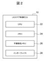
- FIG. 2 is a diagram showing the configuration of the LK steering control ECU 10.
- FIG. ECU is an abbreviation for electronic control unit, and is an electronic control circuit having a microcomputer as a component.
- the LK steering control ECU 10 includes a CPU 22, a memory 24, a nonvolatile memory 26, an interface 28, and the like.
- the CPU 22 includes at least one processor and/or circuit.
- Memory 24 includes, for example, RAM.
- Nonvolatile memory 26 includes, for example, flash memory and ROM.
- the CPU 22 uses the memory 24 as a work memory to execute program codes (instructions) stored in the nonvolatile memory 26 . Thereby, the CPU 22 can execute the processing described below.
- the steering control ECU 12 also has a similar configuration.
- the LK steering control ECU 10 and the steering control ECU 12 may be integrated into one ECU. Additionally, one or more ECUs may be added to perform the processes described below.
- a lane shape sensor (lane shape detection unit) 4 detects and acquires lane shape information about the surrounding area of the vehicle.
- the vehicle peripheral area includes a front area, a right area, and a left area of the vehicle.
- the lane shape information includes lane marking information related to lane markings (for example, white lines) that exist in the area surrounding the vehicle.
- the lane marking information includes the positions of multiple lane markings that define lanes, parameters related to the lane markings, and the like.
- the parameters related to the lane marking include the curvature of the lane marking, the lateral position of the vehicle with respect to the lane marking (the position in the width direction of the road), the yaw angle of the vehicle with respect to the lane marking, and the like.
- the lane shape sensor 4 may be any type of sensor as long as it can acquire the above lane marking information.
- the vehicle behavior sensor (steering torque detection unit) 6 detects and acquires sensor information about the vehicle behavior of the own vehicle, such as information about the driver's steering and the running speed of the own vehicle.
- the information about the driver's steering includes the steering angle of the driver driving the own vehicle, the steering torque, and the like.
- the switching information by the HMI 8 acquires the input information of the control characteristics (explained later) selected by the driver.
- the HMI 8 is composed of switches, a touch panel, etc. that can be operated by the driver who drives the vehicle.
- the LK steering control ECU (lane keeping control unit) 10 reads the information acquired by the lane shape sensor 4, the vehicle behavior sensor 6, and the HMI 8, and maintains traveling within the lane based on the acquired (detected) lane shape (lane A steering command for performing a maintenance run is calculated and output to the steering control ECU 12 (details will be described later).
- the steering control ECU (steering control unit) 12 calculates an instruction (operation amount) for controlling the steering of the vehicle according to the steering command received from the LK steering control ECU 10 and outputs it to the steering actuator 14 .
- the steering actuator 14 is incorporated in the steering mechanism of the vehicle.
- the steering actuator 14 includes a motor for steering the steered wheels (left front wheel and right front wheel) of the vehicle.
- the steering actuator 14 is configured to control the steered wheels of the vehicle according to an instruction (operation amount) from the steering control ECU 12 .
- LK control by LK steering control ECU 10 As mentioned above, the driver's steering wheel operation state during LK control can be divided into two states: "the driver operates the steering wheel intentionally" and “the driver does not actively operate the steering wheel, relying on system functions". There are two control modes. Regarding the requirement for steering control that does not cause discomfort in each of the two control modes for the LK control, the following problems will be described again.
- the system is equipped with multiple lane-keeping modes with different control characteristics, allowing the driver to select the preferred lane-keeping mode and cooperate with the driver. This is handled by switching control characteristics (steering gain).
- the steering gain is increased to increase the amount of torque assist, allowing the driver to keep the lane with a small amount of operation. Therefore, the driver can obtain a system-oriented steering feeling.
- the steering gain is reduced to reduce the amount of torque assist, which requires a large driver operation to keep the lane, and the driver's main steering feeling can be obtained. can be done.
- this problem can be solved by providing the system with a lane-keeping mode that enables the desired steering feeling and allowing the driver to select his or her preference.
- the difference in steering gain between multiple lane-keeping modes is set to be small, thereby suppressing the influence of the steering torque sensor error (steer torque sensor noise) while driving. , the steps in the control characteristics can be reduced.
- the LK steering control ECU 10 includes an LK steering control amount calculation unit 52, a lane keep mode determination unit 54, a correction amount calculation unit 56, and a steering command calculation unit 58, as shown in FIG. is provided as a function block.
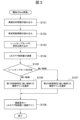
- the LK control by the LK steering control ECU 10 and the operation of each functional block of the LK steering control ECU 10 will be described in detail with reference to the flowchart of FIG.
- This embodiment relates to the cooperation between the driver's steering operation and the steering control while the vehicle is running under the LK control, and is an example showing that the driver can select the desired steering control characteristic to eliminate the sense of incongruity.
- FIG. 10 A flowchart of the LK steering control ECU 10 is shown in FIG. This embodiment is a process that is performed once in a fixed period of time (for example, 50 ms), and its flow will be described below.
- step S101 general lane shape detection results (white line curvature, yaw angle, lateral position, etc.) used in LK control are read (from the lane shape sensor 4).
- step S102 sensor information (vehicle speed, steering angle, steering torque, etc.) related to vehicle behavior used in LK control is read (from the vehicle behavior sensor 6).
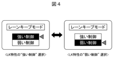
- step S103 which is the lane keeping mode selection process of this embodiment, the lane keeping mode selected by the driver using a switch, touch panel, or the like is read (from the HMI 8).
- Fig. 4 shows an image of selecting from the display of the meter screen with the switch.
- step S104 LK steering control amount calculation unit 52
- the LK steering control amount required for lane keeping traveling on the system is calculated from the information read in steps S101 and S102.
- step S105 (lane keeping mode determination unit 54), the lane keeping mode selected by the driver according to his/her preference is determined from the information read in step S103.
- step S106 If the lane keep mode is "weak control”, proceed to step S106; if "strong control”, proceed to step S107.
- step S106 correction amount calculation unit 56
- a steering gain for weak control is calculated according to a preset first control characteristic.
- the first control characteristic is a steering gain map
- the steering gain is calculated using the torque sensor value (absolute value) that detects the driver's steering operation amount from this steering gain map, and the process proceeds to step S108.
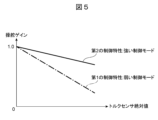
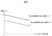
- FIG. 5 shows an image diagram of the steering gain map.
- step S107 correction amount calculation unit 56
- a steering gain for strong control is calculated according to a preset second control characteristic.
- the set value of the steering gain is set larger than that for the first control characteristic to clarify the difference between the control characteristics.
- the steering gain is calculated using the torque sensor value (absolute value) that detects the driver's steering operation amount, and the process proceeds to step S108.
- FIG. 5 shows an image diagram of the steering gain map.
- the steering gain map uses the torque sensor value (absolute value) that detects the driver's steering operation amount as an input, and calculates the steering gain as a correction amount for correcting the LK steering control amount and reflecting it in the steering command. It is a map that defines the relationship between the torque sensor value (absolute value) and the steering gain for output.
- the correction amount calculation unit 56 of the LK steering control ECU 10 selects a first control characteristic (weak control mode) and a second control characteristic (strong control mode) that can be selected according to the driver's preference as the control characteristic of the steering gain map. mode) is set in advance (see FIG. 5).
- the correction amount calculation unit 56 calculates the first control characteristic ( Weak control mode) or the second control characteristic (strong control mode). Then, the correction amount calculation section 56 calculates a steering gain as a correction amount (in other words, corresponding to the torque sensor value) using the torque sensor value according to the selected control characteristic.
- the first and second control characteristics of the steering gain map are set such that the steering gain continuously decreases from the default (1 time) as the torque sensor value increases. .
- the steering gain of the second control characteristic is greater than the steering gain of the first control characteristic (in other words, the steering gain of the second control characteristic is greater than the steering gain of the second control characteristic). is set so that the steering gain of the control characteristic of is small).
- the difference between the steering gains of the first and second control characteristics is set to increase (change) as the torque sensor value increases.
- the setting value of the steering gain of the second control characteristic is larger than that of the first control characteristic (weak control mode), and the first control characteristic is set mainly by the driver's input, If the second control characteristic is set mainly based on the input of the system (the LK steering control ECU 10), the setting example of the steering gain map is not limited to the example shown in FIG.
- the set value of the steering gain of the first control characteristic when the torque sensor value is 0 may be less than the default (1 time).
- the difference between the steering gains of the first and second control characteristics may be constant regardless of the magnitude of the torque sensor value.
- the steering gains of the first and second control characteristics may be constant regardless of the magnitude of the torque sensor value (steering gain g1 of the first control characteristics ⁇ second control Characteristic steering gain g2). Also, although not shown, the steering gain of only one of the first and second control characteristics may be made constant.
- the steering gains of the first and second control characteristics are continuous with respect to the torque sensor value (input steering torque). ), but need not be continuous.
- step S108 steering command calculation unit 58
- the result obtained by multiplying the LK steering control amount obtained in step S104 by the steering gain corresponding to the lane keep mode obtained in step S106 or step S107 is output to the steering control ECU 12 as a steering command.
- the driver selects a preferred lane keeping mode, and the steering gain (first or with the second control characteristic), it is possible to realize the steering control that the driver prefers.
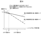
- FIG. 8 shows an image diagram of the steering gain map of the second embodiment.
- the first and second control characteristics reduce the difference between both steering gains and set the steering gain to default (1 time).
- the characteristics are set to be the same (in other words, the characteristics are set to be the same).
- the torque sensor value is lower than a predetermined value (t1)
- different characteristics are set according to the height of the torque sensor value.
- the torque sensor value is higher than a predetermined value (t1)
- the first and second control characteristics are set based on the steering intervention from the driver, the first control characteristic is mainly set by the driver's input, and the second control characteristic is set by the system ( Since the input of the LK steering control ECU 10) is mainly set, when the torque sensor value is higher than the predetermined value (t1), the first control characteristic provides a lower steering gain than the second control characteristic. set to output.
- the steering gains of the first and second control characteristics are set so as to be continuous (have continuity) with respect to the torque sensor value (input steering torque). However, it does not have to be continuous (for example, before and after a predetermined value (t1)).
- the difference between both steering gains is reduced (for example, both steering gains are made to match), and the steering gain approaches the default (1 time). It is possible to suppress the influence of steering torque sensor noise, and control characteristics that emphasize lane tracing can be realized without steps. Even when three or more lane keep mode control characteristics are set, the same effect can be obtained by adding them by this means.
- Example 3 describes the effects of other settings for the first and second control characteristics of Example 1.
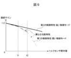
- FIG. 9 shows an image diagram of the steering gain map of the third embodiment.
- the first and second control characteristics reduce the difference between the steering gains of both steering gains when the torque sensor value is lower than the predetermined value (t1).
- the characteristics are set to be equivalent (in other words, the characteristics are set to be equivalent).
- the torque sensor value is higher than the predetermined value (t1)
- different characteristics are set according to the height of the torque sensor value. That is, here, when the torque sensor value is higher than the predetermined value (t1), the steering gain of the first and second control characteristics increases as the torque sensor value increases. It is set so that the difference (corresponding to the characteristic difference) increases (changes).
- the first control characteristic includes a steering gain characteristic that is output when the torque sensor value is lower than a predetermined value (t2: t2>t1), and an output when the torque sensor value is higher than the predetermined value (t2).
- the steering gain characteristics are set to be different.
- the characteristic of the steering gain is the gradient or degree of change of the steering gain with respect to the torque sensor value (input steering torque value). More specifically, the first control characteristic is such that the slope (decrease slope) of the steering gain that is output when the torque sensor value is lower than the predetermined value (t2) is higher than the predetermined value (t2). is set to be smaller than the gradient (decrease gradient) of the steering gain that is output in this case.
- the characteristic of the steering gain that is output around the predetermined values (t1, t2) is changed. You may change the characteristic of the steering gain which carries out.
- the steering gains of the first and second control characteristics are set so as to be continuous (have continuity) with respect to the torque sensor value (input steering torque). However, it does not have to be continuous (for example, before and after a predetermined value (t1, t2)).
- the first and second control characteristics are set with different slopes before and after the predetermined values (t1, t2), thereby further widening the range of the characteristics of the LK control.
- t1, t2 the predetermined values
- the optimum steering feeling can be realized by increasing the change (gradient) of the steering gain with respect to the driver's operation.
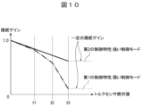
- FIG. 10 shows an image diagram of the steering gain map of the fourth embodiment.
- each of the first and second control characteristics has a characteristic of It is set to be constant (specifically, to output a constant steering gain).
- the steering gains of the first and second control characteristics are set so as to be continuous (have continuity) with respect to the torque sensor value (input steering torque). but need not be continuous (for example, before and after the reference value (t3)).
- the first and second control characteristics are set so that the steering gain is constant in sections where the steering torque is large.
- the steering control amount of the system is determined by the steering gain x the amount of deviation from the center of the lane. By keeping the steering gain constant, the amount of steering control makes it easier to grasp the deviation from the center of the lane. It is possible to communicate the situation.
- the vehicle control device 1 of this embodiment includes a lane shape detection unit (lane shape sensor 4) that detects the shape of the lane around the vehicle, and a steering torque (steer torque) of the driver driving the vehicle.
- lane shape detection unit lane shape sensor 4
- steering torque steering torque
- a steering torque detection unit (vehicle behavior sensor 6) that detects the torque sensor value of the sensor), and a lane maintenance control unit (LK steering control ECU 10 ), and a steering control unit (steering control ECU 12) that controls steering of the vehicle based on a steering command from the lane maintenance control unit (LK steering control ECU 10), and the lane maintenance control unit (LK steering control ECU 10 ) has a plurality of control characteristics including at least a first control characteristic and a second control characteristic that can be selected according to the driver's preference, and switching information input in advance (from the HMI 8) according to the driver's preference. Based on, the first or second control characteristic is selected, the steering control amount required to maintain the running in the lane is calculated, and the selected control characteristic (steering gain calculated by) Based on this, the calculated steering control amount is corrected to calculate the steering command.
- the first and second control characteristics are set based on steering intervention from the driver detected by the steering torque detection unit (vehicle behavior sensor 6).
- the second control characteristic is set mainly by the input of the lane keeping control unit (LK steering control ECU 10) (that is, the value output by the first control characteristic is the second control characteristic). lower than the value that the characteristic outputs).
- the vehicle control device 1 that realizes the driver's preferred steering control characteristics while maintaining lane tracing during LK control.
- each of the above configurations, functions, processing units, processing means, etc. may be realized in hardware, for example, by designing a part or all of them with an integrated circuit.
- each of the above configurations, functions, etc. may be realized by software by a processor interpreting and executing a program for realizing each function.
- Information such as programs, tables, and files that implement each function can be stored in storage devices such as memory, hard disks, SSDs (Solid State Drives), or recording media such as IC cards, SD cards, and DVDs.
- control lines and information lines indicate what is considered necessary for explanation, and not all control lines and information lines are necessarily indicated on the product. In practice, it may be considered that almost all configurations are interconnected.
- vehicle control device 4 lane shape sensor (lane shape detection unit) 6 Vehicle behavior sensor (steering torque detector) 8 HMIs 10 LK steering control ECU (lane keeping control unit) 12 steering control ECU (steering control unit) 14 steering actuator 52 LK steer control amount calculator 54 lane keep mode determination unit 56 correction amount calculator 58 steering command calculator
Landscapes
- Engineering & Computer Science (AREA)
- Automation & Control Theory (AREA)
- Transportation (AREA)
- Mechanical Engineering (AREA)
- Human Computer Interaction (AREA)
- Chemical & Material Sciences (AREA)
- Combustion & Propulsion (AREA)
- Steering Control In Accordance With Driving Conditions (AREA)
Abstract
Description
(車両制御装置の構成)
図1は、本発明の実施例1に係る車両制御装置の構成を示したブロック図である。車両制御装置1は、車両(自車両)に搭載される。車両制御装置1は、LK制御中にステア制御を行うものであり、特に、LK制御によるステア制御とドライバによるステア操作との協調を実現する制御を行うものである。
前述のように、LK制御中のドライバのハンドル操作状態は、「ドライバが意思を持ってハンドルを操作する状態」と「システムの機能に頼り、ドライバがハンドルを積極的に操作しない状態」の2つの制御モードがある。LK制御に対する2つの制御モードそれぞれの状態において違和感のないステア制御が要求される点に関して、以下の問題点を再度説明する。
本実施例2は、実施例1の第1、第2の制御特性について、他の設定による効果を説明する。図8に、本実施例2の操舵ゲインマップのイメージ図を示す。
本実施例3は、実施例1の第1、第2の制御特性について、他の設定による効果を説明する。図9に、本実施例3の操舵ゲインマップのイメージ図を示す。
本実施例4は、実施例1の第1、第2の制御特性について、他の設定による効果を説明する。図10に、本実施例4の操舵ゲインマップのイメージ図を示す。
以上で説明したように、本実施例の車両制御装置1は、車両の周辺の車線形状を検知する車線形状検知部(車線形状センサ4)と、前記車両を運転するドライバの操舵トルク(ステアトルクセンサのトルクセンサ値)を検知する操舵トルク検知部(車両挙動センサ6)と、前記検知した車線形状に基づいて車線内の走行を維持する操舵指令を演算する車線維持制御部(LKステア制御ECU10)と、前記車線維持制御部(LKステア制御ECU10)からの操舵指令に基づいて前記車両の操舵を制御する操舵制御部(操舵制御ECU12)とを備え、前記車線維持制御部(LKステア制御ECU10)は、ドライバの好みに応じて選択可能な第1の制御特性と第2の制御特性を少なくとも含む複数の制御特性を有し、ドライバの好みに応じて予め(HMI8から)入力された切替情報に基づき、前記第1又は第2の制御特性を選択し、前記車線内の走行を維持するために必要な操舵制御量を演算するとともに、前記選択した制御特性(により算出される操舵ゲイン)に基づいて前記演算した操舵制御量を補正して前記操舵指令を演算する。
4 車線形状センサ(車線形状検知部)
6 車両挙動センサ(操舵トルク検知部)
8 HMI
10 LKステア制御ECU(車線維持制御部)
12 操舵制御ECU(操舵制御部)
14 操舵アクチュエータ
52 LKステア制御量演算部
54 レーンキープモード判定部
56 補正量演算部
58 操舵指令演算部
Claims (9)
- 車両の周辺の車線形状を検知する車線形状検知部と、
前記車両を運転するドライバの操舵トルクを検知する操舵トルク検知部と、
前記検知した車線形状に基づいて車線内の走行を維持する操舵指令を演算する車線維持制御部と、
前記車線維持制御部からの操舵指令に基づいて前記車両の操舵を制御する操舵制御部とを備え、
前記車線維持制御部は、
ドライバの好みに応じて選択可能な第1の制御特性と第2の制御特性を少なくとも含む複数の制御特性を有し、
ドライバの好みに応じて予め入力された切替情報に基づき、前記第1又は第2の制御特性を選択し、
前記車線内の走行を維持するために必要な操舵制御量を演算し、前記選択した制御特性に基づいて前記演算した操舵制御量を補正して前記操舵指令を演算することを特徴とする車両制御装置。 - 請求項1に記載の車両制御装置であって、
前記第1及び第2の制御特性は、入力される操舵トルクの値が所定値よりも低い場合は、同等の特性となるように設定され、入力される操舵トルクの値が所定値よりも高い場合は、入力される操舵トルクの値の高さに応じて異なる特性となるように設定されることを特徴とする車両制御装置。 - 請求項2に記載の車両制御装置であって、
前記第1及び第2の制御特性は、前記入力される操舵トルクの値が前記所定値よりも高い場合は、前記入力される操舵トルクの値が高くなるにつれて特性差が大きくなるように設定されることを特徴とする車両制御装置。 - 請求項2に記載の車両制御装置であって、
前記第1及び第2の制御特性はそれぞれ、前記入力される操舵トルクの値が前記所定値よりも大きい基準値よりも高い場合は、前記入力される操舵トルクの値の高さに関わらず一定の特性を有することを特徴とする車両制御装置。 - 請求項1に記載の車両制御装置であって、
前記第1及び第2の制御特性は、前記操舵トルク検知部が検知する前記ドライバからの操舵介入に基づき設定され、
前記第1の制御特性は前記ドライバの入力が主体として設定され、前記第2の制御特性は当該車線維持制御部の入力が主体として設定されることを特徴とする車両制御装置。 - 請求項5に記載の車両制御装置であって、
前記第1及び第2の制御特性は、入力される操舵トルクの値が所定値よりも低い場合は、同等の特性となるように設定され、入力される操舵トルクの値が所定値よりも高い場合は、入力される操舵トルクの値の高さに応じて異なる特性となるように設定され、
前記入力される操舵トルクの値が前記所定値よりも高い場合は、前記第1の制御特性は、前記第2の制御特性よりも低い値を出力することを特徴とする車両制御装置。 - 請求項5に記載の車両制御装置であって、
前記第1及び第2の制御特性は、入力される操舵トルクの値が所定値よりも低い場合は、同等の特性となるように設定され、入力される操舵トルクの値が所定値よりも高い場合は、入力される操舵トルクの値の高さに応じて異なる特性となるように設定され、
前記第1の制御特性は、前記入力される操舵トルクの値が前記所定値とは異なる他の所定値よりも低い場合に出力する操舵ゲインの特性と、前記入力される操舵トルクの値が前記他の所定値よりも高い場合に出力する操舵ゲインの特性が異なることを特徴とする車両制御装置。 - 請求項7に記載の車両制御装置であって、
前記第1の制御特性は、前記入力される操舵トルクの値が前記他の所定値よりも低い場合に出力する操舵ゲインの操舵トルクに対する勾配が、前記入力される操舵トルクの値が前記他の所定値よりも高い場合に出力する操舵ゲインの操舵トルクに対する勾配よりも小さいことを特徴とする車両制御装置。 - 請求項1に記載の車両制御装置であって、
前記第1及び第2の制御特性はそれぞれ、入力される操舵トルクに対して連続性を有することを特徴とする車両制御装置。
Priority Applications (4)
| Application Number | Priority Date | Filing Date | Title |
|---|---|---|---|
| US18/834,651 US12662117B2 (en) | 2022-02-15 | 2022-07-28 | Vehicle control device |
| CN202280090494.XA CN118632803A (zh) | 2022-02-15 | 2022-07-28 | 车辆控制装置 |
| DE112022005775.0T DE112022005775T5 (de) | 2022-02-15 | 2022-07-28 | Fahrzeugsteuervorrichtung |
| JP2024500931A JP7706006B2 (ja) | 2022-02-15 | 2022-07-28 | 車両制御装置 |
Applications Claiming Priority (2)
| Application Number | Priority Date | Filing Date | Title |
|---|---|---|---|
| JP2022021400 | 2022-02-15 | ||
| JP2022-021400 | 2022-02-15 |
Publications (1)
| Publication Number | Publication Date |
|---|---|
| WO2023157337A1 true WO2023157337A1 (ja) | 2023-08-24 |
Family
ID=87577849
Family Applications (1)
| Application Number | Title | Priority Date | Filing Date |
|---|---|---|---|
| PCT/JP2022/029187 Ceased WO2023157337A1 (ja) | 2022-02-15 | 2022-07-28 | 車両制御装置 |
Country Status (5)
| Country | Link |
|---|---|
| US (1) | US12662117B2 (ja) |
| JP (1) | JP7706006B2 (ja) |
| CN (1) | CN118632803A (ja) |
| DE (1) | DE112022005775T5 (ja) |
| WO (1) | WO2023157337A1 (ja) |
Cited By (3)
| Publication number | Priority date | Publication date | Assignee | Title |
|---|---|---|---|---|
| JP2025048570A (ja) * | 2023-09-22 | 2025-04-03 | トヨタ自動車株式会社 | 車両制御装置、車両制御方法及び車両制御プログラム |
| JP2025094556A (ja) * | 2023-12-13 | 2025-06-25 | トヨタ自動車株式会社 | 車両の運転支援制御装置及び運転支援制御方法 |
| JP2025122299A (ja) * | 2024-02-08 | 2025-08-21 | トヨタ自動車株式会社 | 車両の運転支援制御装置、車両の運転支援制御方法及びそのプログラム |
Families Citing this family (1)
| Publication number | Priority date | Publication date | Assignee | Title |
|---|---|---|---|---|
| WO2023175928A1 (ja) * | 2022-03-18 | 2023-09-21 | 日産自動車株式会社 | 運転支援方法及び運転支援装置 |
Citations (3)
| Publication number | Priority date | Publication date | Assignee | Title |
|---|---|---|---|---|
| JP2006264624A (ja) * | 2005-03-25 | 2006-10-05 | Daimler Chrysler Ag | 車線維持支援装置 |
| JP2016159781A (ja) * | 2015-03-02 | 2016-09-05 | 富士重工業株式会社 | 車両の走行制御装置 |
| JP2017202720A (ja) * | 2016-05-10 | 2017-11-16 | 本田技研工業株式会社 | 車両制御システム、車両制御方法、および車両制御プログラム |
Family Cites Families (69)
| Publication number | Priority date | Publication date | Assignee | Title |
|---|---|---|---|---|
| JP4170417B2 (ja) * | 1997-07-01 | 2008-10-22 | 本田技研工業株式会社 | 電動パワーステアリング装置 |
| JP2998928B2 (ja) * | 1997-07-14 | 2000-01-17 | 本田技研工業株式会社 | 電動パワーステアリング装置 |
| JP3968401B2 (ja) * | 1999-07-28 | 2007-08-29 | カヤバ工業株式会社 | 電動式パワーステアリング装置 |
| JP3649119B2 (ja) * | 2000-12-12 | 2005-05-18 | 日産自動車株式会社 | レーンキープアシスト制御装置 |
| US6678594B2 (en) * | 2001-02-02 | 2004-01-13 | Delphi Technologies, Inc. | User-configurable steering control for steer-by-wire systems |
| AU2003236009A1 (en) * | 2002-04-11 | 2003-10-20 | Nsk Ltd. | Vehicle capable of changing vehicle characteristics |
| JP3763472B2 (ja) * | 2002-09-30 | 2006-04-05 | 三菱電機株式会社 | 電動パワーステアリング制御装置 |
| JP4721279B2 (ja) * | 2006-03-29 | 2011-07-13 | 富士重工業株式会社 | 車線追従支援装置 |
| JP4866644B2 (ja) * | 2006-04-10 | 2012-02-01 | オムロンオートモーティブエレクトロニクス株式会社 | 感性識別装置、アシスト力制御装置、アシスト力設定装置、感性識別方法、アシスト力制御方法、アシスト力設定方法、感性識別プログラム、アシスト力制御プログラム、アシスト力設定プログラム、および記録媒体 |
| JP4419997B2 (ja) * | 2006-08-28 | 2010-02-24 | トヨタ自動車株式会社 | 電動パワーステアリング装置 |
| EP2017162B1 (en) * | 2007-07-19 | 2013-06-12 | Nissan Motor Co., Ltd. | In-lane running support system, automobile and in-lane running support method |
| KR101102144B1 (ko) * | 2009-11-17 | 2012-01-02 | 주식회사 만도 | 차선 유지 제어 방법 및 시스템 |
| WO2011111121A1 (ja) * | 2010-03-12 | 2011-09-15 | トヨタ自動車株式会社 | 操舵支援装置 |
| US8965633B2 (en) * | 2011-09-02 | 2015-02-24 | GM Global Technology Operations LLC | System and method for speed adaptive steering override detection during automated lane centering |
| MX355582B (es) * | 2012-10-04 | 2018-04-24 | Nissan Motor | Dispositivo de control de direccion. |
| US8880287B2 (en) * | 2013-03-06 | 2014-11-04 | GM Global Technology Operations LLC | Steering-wheel-hold detection for lane keeping assist feature |
| JP5951116B2 (ja) * | 2013-04-08 | 2016-07-13 | 三菱電機株式会社 | 操舵制御装置および操舵制御方法 |
| JP6213724B2 (ja) * | 2013-09-24 | 2017-10-18 | 日立オートモティブシステムズ株式会社 | パワーステアリング装置 |
| JP5920990B2 (ja) * | 2013-09-27 | 2016-05-24 | 富士重工業株式会社 | 車両のレーンキープ制御装置 |
| JP6156077B2 (ja) * | 2013-11-08 | 2017-07-05 | トヨタ自動車株式会社 | 車両制御装置 |
| KR102183049B1 (ko) * | 2014-04-14 | 2020-11-25 | 주식회사 만도 | Lkas와 연동하는 적응 순항 제어 시스템 및 그의 정속 제어 방법 |
| JP2016222180A (ja) * | 2015-06-02 | 2016-12-28 | 富士重工業株式会社 | 車両操舵制御装置 |
| WO2016199799A1 (ja) * | 2015-06-11 | 2016-12-15 | 日本精工株式会社 | 電動パワーステアリング装置 |
| KR102342142B1 (ko) * | 2015-07-29 | 2021-12-23 | 주식회사 만도모빌리티솔루션즈 | 차선유지 제어방법 및 그 장치 |
| CN107531280B (zh) * | 2015-07-31 | 2019-08-30 | 日立汽车系统株式会社 | 车辆用操舵辅助控制装置 |
| EP3178724B1 (en) * | 2015-12-08 | 2018-10-24 | Volvo Car Corporation | Vehicle steering arrangement, autonomous vehicle steering arrangement, a vehicle, and a method of steering a vehicle |
| CN108701414B (zh) * | 2016-03-31 | 2021-10-08 | 本田技研工业株式会社 | 车辆控制装置、车辆控制方法及存储介质 |
| JP6429203B2 (ja) * | 2016-05-19 | 2018-11-28 | 本田技研工業株式会社 | 車両制御システム、車両制御方法、および車両制御プログラム |
| CN106394668B (zh) * | 2016-09-28 | 2019-02-01 | 北京汽车股份有限公司 | 汽车转向模式的切换方法、系统及汽车 |
| JP6345225B1 (ja) * | 2016-12-21 | 2018-06-20 | 三菱電機株式会社 | 車両用操舵システムおよびレーンキープシステム |
| JP6528786B2 (ja) * | 2017-01-13 | 2019-06-12 | トヨタ自動車株式会社 | 車両の運転支援装置 |
| JP6509940B2 (ja) * | 2017-05-10 | 2019-05-08 | 本田技研工業株式会社 | 運転支援装置および運転支援方法 |
| KR102277285B1 (ko) * | 2017-06-30 | 2021-07-14 | 현대모비스 주식회사 | 후륜 조향 제어 장치 및 방법 |
| US10543853B2 (en) * | 2017-07-05 | 2020-01-28 | Toyota Motor Engineering & Manufacturing North America, Inc. | Systems and methods for providing collaborative control of a vehicle |
| JP7144947B2 (ja) * | 2018-03-14 | 2022-09-30 | 本田技研工業株式会社 | 車両制御装置 |
| DE102018205674A1 (de) * | 2018-04-13 | 2019-10-17 | Deere & Company | Verfahren zur Beeinflussung der Lenkcharakteristik eines landwirtschaftlichen Traktors |
| DE102018210320A1 (de) * | 2018-06-25 | 2020-01-02 | Bayerische Motoren Werke Aktiengesellschaft | Fahrsystem mit einer per Lenkeingriff deaktivierbaren automatisierten Querführung sowie Verfahren zum Deaktivieren einer automatisierten Querführung |
| JP7110812B2 (ja) * | 2018-08-06 | 2022-08-02 | マツダ株式会社 | 車両制御装置および車両制御方法 |
| KR102688999B1 (ko) * | 2018-12-20 | 2024-07-29 | 에이치엘만도 주식회사 | 드라이브 모드 설정 장치 및 드라이브 모드 설정 방법 |
| JP7099970B2 (ja) * | 2019-02-08 | 2022-07-12 | 本田技研工業株式会社 | 車両制御装置 |
| JP6976280B2 (ja) * | 2019-03-28 | 2021-12-08 | 本田技研工業株式会社 | 車両制御装置、車両制御方法、及びプログラム |
| JP7043450B2 (ja) * | 2019-03-28 | 2022-03-29 | 本田技研工業株式会社 | 車両制御装置、車両制御方法、及びプログラム |
| DE102019206980B4 (de) * | 2019-05-14 | 2023-06-22 | Volkswagen Aktiengesellschaft | Verfahren und Lenkungssteuergerät zum Ermitteln einer Stellgröße für das Einstellen eines Servolenkmoments bei einem Fahrzeuglenksystem |
| JP7256958B2 (ja) * | 2019-05-27 | 2023-04-13 | 株式会社ジェイテクト | 電動パワーステアリング装置 |
| JP7272241B2 (ja) * | 2019-11-18 | 2023-05-12 | トヨタ自動車株式会社 | 車両走行制御装置及び車両制御システム |
| JP7537947B2 (ja) * | 2020-08-27 | 2024-08-21 | 株式会社Subaru | 車載システム |
| US12097913B2 (en) * | 2020-08-28 | 2024-09-24 | Polaris Industries Inc. | Vehicle steering systems and methods |
| KR102925228B1 (ko) * | 2020-09-09 | 2026-02-06 | 현대모비스 주식회사 | 차량의 조향 제어 시스템 및 방법 |
| CN115461261B (zh) * | 2020-12-28 | 2023-05-16 | 本田技研工业株式会社 | 车辆控制系统及车辆控制方法 |
| CN114802418B (zh) * | 2021-01-20 | 2024-01-26 | 丰田自动车株式会社 | 转向操纵系统与转向操纵系统的控制方法 |
| JP7780342B2 (ja) * | 2022-01-17 | 2025-12-04 | 本田技研工業株式会社 | 把持検出装置 |
| JP7422798B2 (ja) * | 2022-03-25 | 2024-01-26 | 本田技研工業株式会社 | 運転支援装置、車両、運転支援方法、およびプログラム |
| US12208834B2 (en) * | 2022-03-31 | 2025-01-28 | Caterpillar Inc. | Systems and methods for machine steering |
| JP7537462B2 (ja) * | 2022-03-31 | 2024-08-21 | トヨタ自動車株式会社 | 運転支援装置、運転支援方法及び、プログラム |
| EP4506223B1 (en) * | 2022-04-05 | 2026-05-06 | Nissan Motor Co., Ltd. | Travel assistance method and travel assistance device |
| US20230347919A1 (en) * | 2022-04-28 | 2023-11-02 | Toyota Research Institute, Inc. | Hand friction estimation for estimating guardian user or chauffeur safety driver preference |
| US20230347887A1 (en) * | 2022-04-28 | 2023-11-02 | Toyota Research Institute, Inc. | Systems and methods for driver-preferred lane biasing |
| GB202207467D0 (en) * | 2022-05-20 | 2022-07-06 | Agco Int Gmbh | A steering system and a method of controlling a steering system |
| JP7448588B2 (ja) * | 2022-06-23 | 2024-03-12 | 本田技研工業株式会社 | 運転支援装置、運転支援方法、およびプログラム |
| CN115783039B (zh) * | 2022-12-23 | 2025-07-25 | 小米汽车科技有限公司 | 车辆线控转向系统的扭矩补偿方法及相关装置 |
| JP7816198B2 (ja) * | 2023-01-27 | 2026-02-18 | トヨタ自動車株式会社 | 車両用操舵支援装置及び操舵支援方法 |
| JP7592117B2 (ja) * | 2023-03-28 | 2024-11-29 | 本田技研工業株式会社 | 車両並びにその制御装置及び制御方法 |
| US12428059B2 (en) * | 2023-08-14 | 2025-09-30 | Atieva, Inc. | Manual lane biasing mode for ADAS |
| US20250128760A1 (en) * | 2023-10-20 | 2025-04-24 | Ford Global Technologies, Llc | Methods and apparatus to adjust a steering angle of a vehicle in a self-driving mode |
| US20250155325A1 (en) * | 2023-11-14 | 2025-05-15 | Illinois Tool Works Inc. | Methods and systems for testing coupled hybrid dynamic systems |
| CN121843859A (zh) * | 2023-12-08 | 2026-04-10 | 安斯泰莫株式会社 | 车辆控制装置以及车辆控制方法 |
| JP2025097145A (ja) * | 2023-12-18 | 2025-06-30 | トヨタ自動車株式会社 | 車両操作システム |
| JP7834127B2 (ja) * | 2024-03-28 | 2026-03-23 | 本田技研工業株式会社 | 車両用制御プログラム、車両用制御装置、および車両制御方法 |
| US12497094B2 (en) * | 2024-04-05 | 2025-12-16 | GM Global Technology Operations LLC | Collaborative steering in steer-by-wire systems for automated driving |
-
2022
- 2022-07-28 JP JP2024500931A patent/JP7706006B2/ja active Active
- 2022-07-28 US US18/834,651 patent/US12662117B2/en active Active
- 2022-07-28 CN CN202280090494.XA patent/CN118632803A/zh active Pending
- 2022-07-28 DE DE112022005775.0T patent/DE112022005775T5/de active Pending
- 2022-07-28 WO PCT/JP2022/029187 patent/WO2023157337A1/ja not_active Ceased
Patent Citations (3)
| Publication number | Priority date | Publication date | Assignee | Title |
|---|---|---|---|---|
| JP2006264624A (ja) * | 2005-03-25 | 2006-10-05 | Daimler Chrysler Ag | 車線維持支援装置 |
| JP2016159781A (ja) * | 2015-03-02 | 2016-09-05 | 富士重工業株式会社 | 車両の走行制御装置 |
| JP2017202720A (ja) * | 2016-05-10 | 2017-11-16 | 本田技研工業株式会社 | 車両制御システム、車両制御方法、および車両制御プログラム |
Cited By (4)
| Publication number | Priority date | Publication date | Assignee | Title |
|---|---|---|---|---|
| JP2025048570A (ja) * | 2023-09-22 | 2025-04-03 | トヨタ自動車株式会社 | 車両制御装置、車両制御方法及び車両制御プログラム |
| JP2025094556A (ja) * | 2023-12-13 | 2025-06-25 | トヨタ自動車株式会社 | 車両の運転支援制御装置及び運転支援制御方法 |
| US12686386B2 (en) | 2023-12-13 | 2026-07-21 | Toyota Jidosha Kabushiki Kaisha | Driving assistance control apparatus for vehicle, driving assistance control method for vehicle, and non-transitory storage medium storing program thereof |
| JP2025122299A (ja) * | 2024-02-08 | 2025-08-21 | トヨタ自動車株式会社 | 車両の運転支援制御装置、車両の運転支援制御方法及びそのプログラム |
Also Published As
| Publication number | Publication date |
|---|---|
| JPWO2023157337A1 (ja) | 2023-08-24 |
| US12662117B2 (en) | 2026-06-23 |
| CN118632803A (zh) | 2024-09-10 |
| JP7706006B2 (ja) | 2025-07-10 |
| DE112022005775T5 (de) | 2024-12-12 |
| US20250136107A1 (en) | 2025-05-01 |
Similar Documents
| Publication | Publication Date | Title |
|---|---|---|
| JP7706006B2 (ja) | 車両制御装置 | |
| JP6863011B2 (ja) | 操舵制御装置 | |
| CN105980238B (zh) | 车辆转向控制装置 | |
| EP1867557B1 (en) | Vehicle steering system | |
| JP2017518923A (ja) | パワーステアリングの管理方法、及び、その管理モジュール | |
| JP2538939B2 (ja) | 車両の舵角制御装置 | |
| JP7705466B2 (ja) | 車両の電動機械式操舵手段を制御するためのシステム及び方法 | |
| KR20180062958A (ko) | 차선 내 주행 지원 장치 | |
| CN105711640A (zh) | 确定用于调节操纵设备的结果额定值的方法和装置及车辆 | |
| US12043254B2 (en) | Vehicle control device and vehicle control method | |
| EP1426267A2 (en) | Steering control device | |
| JP2022060934A (ja) | 車両の車線逸脱抑制制御装置 | |
| JP2003118610A (ja) | 電動パワーステアリング制御装置 | |
| JP2016107658A (ja) | 車両の操舵制御装置及び車両の操舵制御方法 | |
| JP7032262B2 (ja) | 車両の操舵制御装置 | |
| JP2012126359A (ja) | 操舵装置 | |
| JP2014144745A (ja) | 車両の走行制御装置 | |
| JP2024072643A (ja) | 操舵制御装置 | |
| JP2021054337A (ja) | 操舵制御装置及び操舵制御方法 | |
| JP2020104735A (ja) | 車両制御方法及び車両制御装置 | |
| JP2002193120A (ja) | 電動パワーステアリング装置 | |
| CN116963956A (zh) | 用于影响车辆行为的设备和方法 | |
| JP4438132B2 (ja) | 車両用操舵制御装置 | |
| KR101951213B1 (ko) | LKAS와 FlexSteer의 협조제어를 통한 MDPS 제어 방법 | |
| KR20130091523A (ko) | Lkas의 성능 향상 장치 및 방법 |
Legal Events
| Date | Code | Title | Description |
|---|---|---|---|
| 121 | Ep: the epo has been informed by wipo that ep was designated in this application |
Ref document number: 22927235 Country of ref document: EP Kind code of ref document: A1 |
|
| ENP | Entry into the national phase |
Ref document number: 2024500931 Country of ref document: JP Kind code of ref document: A |
|
| WWE | Wipo information: entry into national phase |
Ref document number: 202280090494.X Country of ref document: CN |
|
| WWE | Wipo information: entry into national phase |
Ref document number: 18834651 Country of ref document: US Ref document number: 112022005775 Country of ref document: DE |
|
| 122 | Ep: pct application non-entry in european phase |
Ref document number: 22927235 Country of ref document: EP Kind code of ref document: A1 |
|
| WWP | Wipo information: published in national office |
Ref document number: 18834651 Country of ref document: US |
|
| WWG | Wipo information: grant in national office |
Ref document number: 18834651 Country of ref document: US |