WO2022243782A1 - 正極活物質の作製方法、正極、リチウムイオン二次電池、移動体、蓄電システム、及び電子機器 - Google Patents
正極活物質の作製方法、正極、リチウムイオン二次電池、移動体、蓄電システム、及び電子機器 Download PDFInfo
- Publication number
- WO2022243782A1 WO2022243782A1 PCT/IB2022/054259 IB2022054259W WO2022243782A1 WO 2022243782 A1 WO2022243782 A1 WO 2022243782A1 IB 2022054259 W IB2022054259 W IB 2022054259W WO 2022243782 A1 WO2022243782 A1 WO 2022243782A1
- Authority
- WO
- WIPO (PCT)
- Prior art keywords
- positive electrode
- active material
- electrode active
- source
- lithium
- Prior art date
Links
- 239000007774 positive electrode material Substances 0.000 title claims abstract description 294
- 238000004519 manufacturing process Methods 0.000 title claims abstract description 56
- 238000003860 storage Methods 0.000 title claims description 84
- HBBGRARXTFLTSG-UHFFFAOYSA-N Lithium ion Chemical compound [Li+] HBBGRARXTFLTSG-UHFFFAOYSA-N 0.000 title claims description 40
- 229910001416 lithium ion Inorganic materials 0.000 title claims description 40
- PQXKHYXIUOZZFA-UHFFFAOYSA-M lithium fluoride Chemical compound [Li+].[F-] PQXKHYXIUOZZFA-UHFFFAOYSA-M 0.000 claims abstract description 189
- 229910052744 lithium Inorganic materials 0.000 claims abstract description 137
- WHXSMMKQMYFTQS-UHFFFAOYSA-N Lithium Chemical compound [Li] WHXSMMKQMYFTQS-UHFFFAOYSA-N 0.000 claims abstract description 126
- 239000000203 mixture Substances 0.000 claims abstract description 121
- PXHVJJICTQNCMI-UHFFFAOYSA-N Nickel Chemical compound [Ni] PXHVJJICTQNCMI-UHFFFAOYSA-N 0.000 claims abstract description 102
- 239000011777 magnesium Substances 0.000 claims abstract description 85
- 229910052749 magnesium Inorganic materials 0.000 claims abstract description 81
- FYYHWMGAXLPEAU-UHFFFAOYSA-N Magnesium Chemical compound [Mg] FYYHWMGAXLPEAU-UHFFFAOYSA-N 0.000 claims abstract description 80
- 239000002131 composite material Substances 0.000 claims abstract description 71
- GUTLYIVDDKVIGB-UHFFFAOYSA-N cobalt atom Chemical compound [Co] GUTLYIVDDKVIGB-UHFFFAOYSA-N 0.000 claims abstract description 68
- 229910052731 fluorine Inorganic materials 0.000 claims abstract description 67
- 229910017052 cobalt Inorganic materials 0.000 claims abstract description 66
- 239000010941 cobalt Substances 0.000 claims abstract description 66
- 239000011737 fluorine Substances 0.000 claims abstract description 66
- YCKRFDGAMUMZLT-UHFFFAOYSA-N Fluorine atom Chemical compound [F] YCKRFDGAMUMZLT-UHFFFAOYSA-N 0.000 claims abstract description 63
- 229910052782 aluminium Inorganic materials 0.000 claims abstract description 59
- XAGFODPZIPBFFR-UHFFFAOYSA-N aluminium Chemical compound [Al] XAGFODPZIPBFFR-UHFFFAOYSA-N 0.000 claims abstract description 56
- 229910052788 barium Inorganic materials 0.000 claims abstract description 51
- 229910052759 nickel Inorganic materials 0.000 claims abstract description 51
- DSAJWYNOEDNPEQ-UHFFFAOYSA-N barium atom Chemical compound [Ba] DSAJWYNOEDNPEQ-UHFFFAOYSA-N 0.000 claims abstract description 49
- 229910001632 barium fluoride Inorganic materials 0.000 claims abstract description 39
- OYLGJCQECKOTOL-UHFFFAOYSA-L barium fluoride Chemical compound [F-].[F-].[Ba+2] OYLGJCQECKOTOL-UHFFFAOYSA-L 0.000 claims abstract description 38
- 238000002156 mixing Methods 0.000 claims abstract description 35
- ORUIBWPALBXDOA-UHFFFAOYSA-L magnesium fluoride Chemical compound [F-].[F-].[Mg+2] ORUIBWPALBXDOA-UHFFFAOYSA-L 0.000 claims abstract description 32
- 229910001635 magnesium fluoride Inorganic materials 0.000 claims abstract description 27
- 238000010438 heat treatment Methods 0.000 claims description 126
- 229910016036 BaF 2 Inorganic materials 0.000 claims description 47
- 239000007784 solid electrolyte Substances 0.000 claims description 35
- 239000003792 electrolyte Substances 0.000 claims description 20
- 239000003575 carbonaceous material Substances 0.000 claims description 5
- 239000013078 crystal Substances 0.000 description 196
- 239000000654 additive Substances 0.000 description 191
- 230000000996 additive effect Effects 0.000 description 191
- 239000010410 layer Substances 0.000 description 102
- 239000000463 material Substances 0.000 description 85
- OKTJSMMVPCPJKN-UHFFFAOYSA-N Carbon Chemical compound [C] OKTJSMMVPCPJKN-UHFFFAOYSA-N 0.000 description 83
- 229910021389 graphene Inorganic materials 0.000 description 82
- 239000002245 particle Substances 0.000 description 73
- -1 graphene compound Chemical class 0.000 description 67
- 239000002344 surface layer Substances 0.000 description 65
- 229910052723 transition metal Inorganic materials 0.000 description 58
- 150000003624 transition metals Chemical class 0.000 description 57
- 238000000034 method Methods 0.000 description 53
- 239000011149 active material Substances 0.000 description 51
- QVGXLLKOCUKJST-UHFFFAOYSA-N atomic oxygen Chemical compound [O] QVGXLLKOCUKJST-UHFFFAOYSA-N 0.000 description 51
- 229910052760 oxygen Inorganic materials 0.000 description 51
- 239000001301 oxygen Substances 0.000 description 51
- 230000006870 function Effects 0.000 description 43
- 239000004020 conductor Substances 0.000 description 36
- 238000007599 discharging Methods 0.000 description 35
- 239000007773 negative electrode material Substances 0.000 description 35
- 235000002639 sodium chloride Nutrition 0.000 description 34
- FAPWRFPIFSIZLT-UHFFFAOYSA-M Sodium chloride Chemical group [Na+].[Cl-] FAPWRFPIFSIZLT-UHFFFAOYSA-M 0.000 description 33
- 239000012298 atmosphere Substances 0.000 description 32
- 239000011780 sodium chloride Substances 0.000 description 31
- 239000004065 semiconductor Substances 0.000 description 28
- 210000004027 cell Anatomy 0.000 description 27
- 238000010586 diagram Methods 0.000 description 26
- 239000010408 film Substances 0.000 description 26
- 229910018871 CoO 2 Inorganic materials 0.000 description 25
- 229910015118 LiMO Inorganic materials 0.000 description 25
- 238000002441 X-ray diffraction Methods 0.000 description 25
- 238000006243 chemical reaction Methods 0.000 description 24
- 239000008151 electrolyte solution Substances 0.000 description 24
- 230000002829 reductive effect Effects 0.000 description 22
- 102100027368 Histone H1.3 Human genes 0.000 description 21
- 101001009450 Homo sapiens Histone H1.3 Proteins 0.000 description 21
- 229910012851 LiCoO 2 Inorganic materials 0.000 description 21
- 230000001965 increasing effect Effects 0.000 description 21
- 239000011230 binding agent Substances 0.000 description 20
- 238000009826 distribution Methods 0.000 description 20
- 229910052751 metal Inorganic materials 0.000 description 20
- 230000008859 change Effects 0.000 description 18
- 238000005259 measurement Methods 0.000 description 18
- 239000000523 sample Substances 0.000 description 18
- 230000000694 effects Effects 0.000 description 17
- MCMNRKCIXSYSNV-UHFFFAOYSA-N Zirconium dioxide Chemical compound O=[Zr]=O MCMNRKCIXSYSNV-UHFFFAOYSA-N 0.000 description 16
- 150000001450 anions Chemical class 0.000 description 16
- 229910000625 lithium cobalt oxide Inorganic materials 0.000 description 16
- BFZPBUKRYWOWDV-UHFFFAOYSA-N lithium;oxido(oxo)cobalt Chemical compound [Li+].[O-][Co]=O BFZPBUKRYWOWDV-UHFFFAOYSA-N 0.000 description 16
- 239000002184 metal Substances 0.000 description 16
- ZOXJGFHDIHLPTG-UHFFFAOYSA-N Boron Chemical compound [B] ZOXJGFHDIHLPTG-UHFFFAOYSA-N 0.000 description 14
- XUIMIQQOPSSXEZ-UHFFFAOYSA-N Silicon Chemical compound [Si] XUIMIQQOPSSXEZ-UHFFFAOYSA-N 0.000 description 14
- 230000005540 biological transmission Effects 0.000 description 14
- 229910052796 boron Inorganic materials 0.000 description 14
- 150000001875 compounds Chemical class 0.000 description 14
- 238000002149 energy-dispersive X-ray emission spectroscopy Methods 0.000 description 14
- 230000001976 improved effect Effects 0.000 description 14
- 229910052710 silicon Inorganic materials 0.000 description 14
- 239000010703 silicon Substances 0.000 description 14
- 239000011701 zinc Substances 0.000 description 14
- RTAQQCXQSZGOHL-UHFFFAOYSA-N Titanium Chemical compound [Ti] RTAQQCXQSZGOHL-UHFFFAOYSA-N 0.000 description 13
- 238000000354 decomposition reaction Methods 0.000 description 13
- 229910052733 gallium Inorganic materials 0.000 description 13
- 229910052719 titanium Inorganic materials 0.000 description 13
- 239000010936 titanium Substances 0.000 description 13
- GYHNNYVSQQEPJS-UHFFFAOYSA-N Gallium Chemical compound [Ga] GYHNNYVSQQEPJS-UHFFFAOYSA-N 0.000 description 12
- 238000004458 analytical method Methods 0.000 description 12
- 238000011156 evaluation Methods 0.000 description 12
- 229910002804 graphite Inorganic materials 0.000 description 12
- 239000010439 graphite Substances 0.000 description 12
- 229910052738 indium Inorganic materials 0.000 description 12
- WPBNNNQJVZRUHP-UHFFFAOYSA-L manganese(2+);methyl n-[[2-(methoxycarbonylcarbamothioylamino)phenyl]carbamothioyl]carbamate;n-[2-(sulfidocarbothioylamino)ethyl]carbamodithioate Chemical compound [Mn+2].[S-]C(=S)NCCNC([S-])=S.COC(=O)NC(=S)NC1=CC=CC=C1NC(=S)NC(=O)OC WPBNNNQJVZRUHP-UHFFFAOYSA-L 0.000 description 12
- 238000002844 melting Methods 0.000 description 12
- 230000008018 melting Effects 0.000 description 12
- 238000010298 pulverizing process Methods 0.000 description 12
- LIVNPJMFVYWSIS-UHFFFAOYSA-N silicon monoxide Chemical compound [Si-]#[O+] LIVNPJMFVYWSIS-UHFFFAOYSA-N 0.000 description 12
- 239000002904 solvent Substances 0.000 description 12
- 239000012535 impurity Substances 0.000 description 11
- APFVFJFRJDLVQX-UHFFFAOYSA-N indium atom Chemical compound [In] APFVFJFRJDLVQX-UHFFFAOYSA-N 0.000 description 11
- XEEYBQQBJWHFJM-UHFFFAOYSA-N Iron Chemical compound [Fe] XEEYBQQBJWHFJM-UHFFFAOYSA-N 0.000 description 10
- 150000001768 cations Chemical class 0.000 description 10
- 230000007547 defect Effects 0.000 description 10
- 238000009792 diffusion process Methods 0.000 description 10
- 229920000642 polymer Polymers 0.000 description 10
- 238000001878 scanning electron micrograph Methods 0.000 description 10
- 238000000859 sublimation Methods 0.000 description 10
- 230000008022 sublimation Effects 0.000 description 10
- 229910052799 carbon Inorganic materials 0.000 description 9
- 238000001816 cooling Methods 0.000 description 9
- 238000001514 detection method Methods 0.000 description 9
- 229910052698 phosphorus Inorganic materials 0.000 description 9
- OIFBSDVPJOWBCH-UHFFFAOYSA-N Diethyl carbonate Chemical compound CCOC(=O)OCC OIFBSDVPJOWBCH-UHFFFAOYSA-N 0.000 description 8
- KMTRUDSVKNLOMY-UHFFFAOYSA-N Ethylene carbonate Chemical compound O=C1OCCO1 KMTRUDSVKNLOMY-UHFFFAOYSA-N 0.000 description 8
- 239000002033 PVDF binder Substances 0.000 description 8
- OAICVXFJPJFONN-UHFFFAOYSA-N Phosphorus Chemical compound [P] OAICVXFJPJFONN-UHFFFAOYSA-N 0.000 description 8
- 239000011651 chromium Substances 0.000 description 8
- 238000001704 evaporation Methods 0.000 description 8
- 230000008020 evaporation Effects 0.000 description 8
- 239000012212 insulator Substances 0.000 description 8
- 239000011574 phosphorus Substances 0.000 description 8
- 229920002981 polyvinylidene fluoride Polymers 0.000 description 8
- CSCPPACGZOOCGX-UHFFFAOYSA-N Acetone Chemical compound CC(C)=O CSCPPACGZOOCGX-UHFFFAOYSA-N 0.000 description 7
- 239000004743 Polypropylene Substances 0.000 description 7
- 229910045601 alloy Inorganic materials 0.000 description 7
- 239000000956 alloy Substances 0.000 description 7
- PNEYBMLMFCGWSK-UHFFFAOYSA-N aluminium oxide Inorganic materials [O-2].[O-2].[O-2].[Al+3].[Al+3] PNEYBMLMFCGWSK-UHFFFAOYSA-N 0.000 description 7
- 229920002678 cellulose Chemical class 0.000 description 7
- 239000001913 cellulose Chemical class 0.000 description 7
- 238000004140 cleaning Methods 0.000 description 7
- 230000007797 corrosion Effects 0.000 description 7
- 238000005260 corrosion Methods 0.000 description 7
- 230000006866 deterioration Effects 0.000 description 7
- 230000005496 eutectics Effects 0.000 description 7
- CPLXHLVBOLITMK-UHFFFAOYSA-N magnesium oxide Inorganic materials [Mg]=O CPLXHLVBOLITMK-UHFFFAOYSA-N 0.000 description 7
- 230000007246 mechanism Effects 0.000 description 7
- TWNQGVIAIRXVLR-UHFFFAOYSA-N oxo(oxoalumanyloxy)alumane Chemical compound O=[Al]O[Al]=O TWNQGVIAIRXVLR-UHFFFAOYSA-N 0.000 description 7
- 125000004430 oxygen atom Chemical group O* 0.000 description 7
- 229920001155 polypropylene Polymers 0.000 description 7
- 230000003746 surface roughness Effects 0.000 description 7
- 229910052725 zinc Inorganic materials 0.000 description 7
- VAYTZRYEBVHVLE-UHFFFAOYSA-N 1,3-dioxol-2-one Chemical compound O=C1OC=CO1 VAYTZRYEBVHVLE-UHFFFAOYSA-N 0.000 description 6
- WEVYAHXRMPXWCK-UHFFFAOYSA-N Acetonitrile Chemical compound CC#N WEVYAHXRMPXWCK-UHFFFAOYSA-N 0.000 description 6
- VYZAMTAEIAYCRO-UHFFFAOYSA-N Chromium Chemical compound [Cr] VYZAMTAEIAYCRO-UHFFFAOYSA-N 0.000 description 6
- KRHYYFGTRYWZRS-UHFFFAOYSA-N Fluorane Chemical compound F KRHYYFGTRYWZRS-UHFFFAOYSA-N 0.000 description 6
- PWHULOQIROXLJO-UHFFFAOYSA-N Manganese Chemical compound [Mn] PWHULOQIROXLJO-UHFFFAOYSA-N 0.000 description 6
- SECXISVLQFMRJM-UHFFFAOYSA-N N-Methylpyrrolidone Chemical compound CN1CCCC1=O SECXISVLQFMRJM-UHFFFAOYSA-N 0.000 description 6
- HCHKCACWOHOZIP-UHFFFAOYSA-N Zinc Chemical compound [Zn] HCHKCACWOHOZIP-UHFFFAOYSA-N 0.000 description 6
- QCWXUUIWCKQGHC-UHFFFAOYSA-N Zirconium Chemical compound [Zr] QCWXUUIWCKQGHC-UHFFFAOYSA-N 0.000 description 6
- 239000006230 acetylene black Substances 0.000 description 6
- 229920003235 aromatic polyamide Polymers 0.000 description 6
- 230000008901 benefit Effects 0.000 description 6
- 229910052804 chromium Inorganic materials 0.000 description 6
- 238000004891 communication Methods 0.000 description 6
- 239000010949 copper Substances 0.000 description 6
- 238000003795 desorption Methods 0.000 description 6
- 229910052748 manganese Inorganic materials 0.000 description 6
- 239000011572 manganese Substances 0.000 description 6
- 150000002739 metals Chemical class 0.000 description 6
- 229910052758 niobium Inorganic materials 0.000 description 6
- 239000010955 niobium Substances 0.000 description 6
- GUCVJGMIXFAOAE-UHFFFAOYSA-N niobium atom Chemical compound [Nb] GUCVJGMIXFAOAE-UHFFFAOYSA-N 0.000 description 6
- 230000008569 process Effects 0.000 description 6
- 229910001220 stainless steel Inorganic materials 0.000 description 6
- 239000010935 stainless steel Substances 0.000 description 6
- 229910052720 vanadium Inorganic materials 0.000 description 6
- GPPXJZIENCGNKB-UHFFFAOYSA-N vanadium Chemical compound [V]#[V] GPPXJZIENCGNKB-UHFFFAOYSA-N 0.000 description 6
- 229920003169 water-soluble polymer Polymers 0.000 description 6
- 229910052726 zirconium Inorganic materials 0.000 description 6
- 229920002134 Carboxymethyl cellulose Polymers 0.000 description 5
- KRHYYFGTRYWZRS-UHFFFAOYSA-M Fluoride anion Chemical compound [F-] KRHYYFGTRYWZRS-UHFFFAOYSA-M 0.000 description 5
- 230000005536 Jahn Teller effect Effects 0.000 description 5
- 229920003171 Poly (ethylene oxide) Polymers 0.000 description 5
- UCKMPCXJQFINFW-UHFFFAOYSA-N Sulphide Chemical compound [S-2] UCKMPCXJQFINFW-UHFFFAOYSA-N 0.000 description 5
- KLARSDUHONHPRF-UHFFFAOYSA-N [Li].[Mn] Chemical compound [Li].[Mn] KLARSDUHONHPRF-UHFFFAOYSA-N 0.000 description 5
- 230000002411 adverse Effects 0.000 description 5
- 239000004760 aramid Substances 0.000 description 5
- 229910021383 artificial graphite Inorganic materials 0.000 description 5
- 230000015572 biosynthetic process Effects 0.000 description 5
- 239000003990 capacitor Substances 0.000 description 5
- 239000000919 ceramic Substances 0.000 description 5
- 229910052802 copper Inorganic materials 0.000 description 5
- 238000000605 extraction Methods 0.000 description 5
- 125000000524 functional group Chemical group 0.000 description 5
- 238000003780 insertion Methods 0.000 description 5
- 230000037431 insertion Effects 0.000 description 5
- 150000002500 ions Chemical class 0.000 description 5
- 229910052742 iron Inorganic materials 0.000 description 5
- 229910044991 metal oxide Inorganic materials 0.000 description 5
- 150000004706 metal oxides Chemical class 0.000 description 5
- 229910052750 molybdenum Inorganic materials 0.000 description 5
- 229910021421 monocrystalline silicon Inorganic materials 0.000 description 5
- 239000004570 mortar (masonry) Substances 0.000 description 5
- 239000012071 phase Substances 0.000 description 5
- 229920005989 resin Polymers 0.000 description 5
- 239000011347 resin Substances 0.000 description 5
- 239000002002 slurry Substances 0.000 description 5
- 239000007787 solid Substances 0.000 description 5
- 229910052717 sulfur Inorganic materials 0.000 description 5
- 229910018626 Al(OH) Inorganic materials 0.000 description 4
- RYGMFSIKBFXOCR-UHFFFAOYSA-N Copper Chemical compound [Cu] RYGMFSIKBFXOCR-UHFFFAOYSA-N 0.000 description 4
- UQSXHKLRYXJYBZ-UHFFFAOYSA-N Iron oxide Chemical compound [Fe]=O UQSXHKLRYXJYBZ-UHFFFAOYSA-N 0.000 description 4
- ZOKXTWBITQBERF-UHFFFAOYSA-N Molybdenum Chemical compound [Mo] ZOKXTWBITQBERF-UHFFFAOYSA-N 0.000 description 4
- 229910018661 Ni(OH) Inorganic materials 0.000 description 4
- VYPSYNLAJGMNEJ-UHFFFAOYSA-N Silicium dioxide Chemical compound O=[Si]=O VYPSYNLAJGMNEJ-UHFFFAOYSA-N 0.000 description 4
- NINIDFKCEFEMDL-UHFFFAOYSA-N Sulfur Chemical compound [S] NINIDFKCEFEMDL-UHFFFAOYSA-N 0.000 description 4
- 239000012300 argon atmosphere Substances 0.000 description 4
- 239000011324 bead Substances 0.000 description 4
- 229910010293 ceramic material Inorganic materials 0.000 description 4
- 239000011248 coating agent Substances 0.000 description 4
- 238000000576 coating method Methods 0.000 description 4
- 239000000428 dust Substances 0.000 description 4
- 229920001971 elastomer Polymers 0.000 description 4
- 230000005684 electric field Effects 0.000 description 4
- 238000010894 electron beam technology Methods 0.000 description 4
- 150000002222 fluorine compounds Chemical class 0.000 description 4
- 230000004907 flux Effects 0.000 description 4
- 239000011888 foil Substances 0.000 description 4
- 229910052732 germanium Inorganic materials 0.000 description 4
- 229910052735 hafnium Inorganic materials 0.000 description 4
- VBJZVLUMGGDVMO-UHFFFAOYSA-N hafnium atom Chemical compound [Hf] VBJZVLUMGGDVMO-UHFFFAOYSA-N 0.000 description 4
- 238000001095 inductively coupled plasma mass spectrometry Methods 0.000 description 4
- 239000011810 insulating material Substances 0.000 description 4
- AMXOYNBUYSYVKV-UHFFFAOYSA-M lithium bromide Chemical compound [Li+].[Br-] AMXOYNBUYSYVKV-UHFFFAOYSA-M 0.000 description 4
- 239000000395 magnesium oxide Substances 0.000 description 4
- 239000002931 mesocarbon microbead Substances 0.000 description 4
- VNWKTOKETHGBQD-UHFFFAOYSA-N methane Chemical compound C VNWKTOKETHGBQD-UHFFFAOYSA-N 0.000 description 4
- 239000011733 molybdenum Substances 0.000 description 4
- 229910000480 nickel oxide Inorganic materials 0.000 description 4
- 150000004767 nitrides Chemical class 0.000 description 4
- 230000036961 partial effect Effects 0.000 description 4
- 230000002093 peripheral effect Effects 0.000 description 4
- BASFCYQUMIYNBI-UHFFFAOYSA-N platinum Chemical compound [Pt] BASFCYQUMIYNBI-UHFFFAOYSA-N 0.000 description 4
- 229920002647 polyamide Polymers 0.000 description 4
- 230000009467 reduction Effects 0.000 description 4
- 239000005060 rubber Substances 0.000 description 4
- 238000007789 sealing Methods 0.000 description 4
- 125000006850 spacer group Chemical group 0.000 description 4
- 239000007858 starting material Substances 0.000 description 4
- 239000011593 sulfur Substances 0.000 description 4
- 238000005211 surface analysis Methods 0.000 description 4
- 230000002195 synergetic effect Effects 0.000 description 4
- YTZKOQUCBOVLHL-UHFFFAOYSA-N tert-butylbenzene Chemical compound CC(C)(C)C1=CC=CC=C1 YTZKOQUCBOVLHL-UHFFFAOYSA-N 0.000 description 4
- 229910052721 tungsten Inorganic materials 0.000 description 4
- XLYOFNOQVPJJNP-UHFFFAOYSA-N water Substances O XLYOFNOQVPJJNP-UHFFFAOYSA-N 0.000 description 4
- HEZMWWAKWCSUCB-PHDIDXHHSA-N (3R,4R)-3,4-dihydroxycyclohexa-1,5-diene-1-carboxylic acid Chemical compound O[C@@H]1C=CC(C(O)=O)=C[C@H]1O HEZMWWAKWCSUCB-PHDIDXHHSA-N 0.000 description 3
- OYPRJOBELJOOCE-UHFFFAOYSA-N Calcium Chemical group [Ca] OYPRJOBELJOOCE-UHFFFAOYSA-N 0.000 description 3
- 229910021583 Cobalt(III) fluoride Inorganic materials 0.000 description 3
- RTZKZFJDLAIYFH-UHFFFAOYSA-N Diethyl ether Chemical compound CCOCC RTZKZFJDLAIYFH-UHFFFAOYSA-N 0.000 description 3
- XEKOWRVHYACXOJ-UHFFFAOYSA-N Ethyl acetate Chemical compound CCOC(C)=O XEKOWRVHYACXOJ-UHFFFAOYSA-N 0.000 description 3
- 229910002984 Li7La3Zr2O12 Inorganic materials 0.000 description 3
- 229910013290 LiNiO 2 Inorganic materials 0.000 description 3
- 229910013870 LiPF 6 Inorganic materials 0.000 description 3
- WMFOQBRAJBCJND-UHFFFAOYSA-M Lithium hydroxide Chemical compound [Li+].[OH-] WMFOQBRAJBCJND-UHFFFAOYSA-M 0.000 description 3
- 239000004677 Nylon Substances 0.000 description 3
- 239000004372 Polyvinyl alcohol Substances 0.000 description 3
- 238000003991 Rietveld refinement Methods 0.000 description 3
- 238000003917 TEM image Methods 0.000 description 3
- GWEVSGVZZGPLCZ-UHFFFAOYSA-N Titan oxide Chemical compound O=[Ti]=O GWEVSGVZZGPLCZ-UHFFFAOYSA-N 0.000 description 3
- 229910052785 arsenic Inorganic materials 0.000 description 3
- 125000004429 atom Chemical group 0.000 description 3
- QVQLCTNNEUAWMS-UHFFFAOYSA-N barium oxide Chemical compound [Ba]=O QVQLCTNNEUAWMS-UHFFFAOYSA-N 0.000 description 3
- JFDZBHWFFUWGJE-UHFFFAOYSA-N benzonitrile Chemical compound N#CC1=CC=CC=C1 JFDZBHWFFUWGJE-UHFFFAOYSA-N 0.000 description 3
- 229910052791 calcium Inorganic materials 0.000 description 3
- 239000011575 calcium Chemical group 0.000 description 3
- 238000004364 calculation method Methods 0.000 description 3
- 239000001768 carboxy methyl cellulose Substances 0.000 description 3
- 235000010948 carboxy methyl cellulose Nutrition 0.000 description 3
- 239000008112 carboxymethyl-cellulose Substances 0.000 description 3
- 229910000428 cobalt oxide Inorganic materials 0.000 description 3
- 239000012141 concentrate Substances 0.000 description 3
- 239000000470 constituent Substances 0.000 description 3
- 229920001577 copolymer Polymers 0.000 description 3
- 238000000151 deposition Methods 0.000 description 3
- 230000008021 deposition Effects 0.000 description 3
- 238000006073 displacement reaction Methods 0.000 description 3
- 230000005611 electricity Effects 0.000 description 3
- 238000010828 elution Methods 0.000 description 3
- 125000001153 fluoro group Chemical group F* 0.000 description 3
- GNPVGFCGXDBREM-UHFFFAOYSA-N germanium atom Chemical compound [Ge] GNPVGFCGXDBREM-UHFFFAOYSA-N 0.000 description 3
- 239000011521 glass Substances 0.000 description 3
- 150000004676 glycans Chemical class 0.000 description 3
- 150000004820 halides Chemical class 0.000 description 3
- 230000006872 improvement Effects 0.000 description 3
- 238000009830 intercalation Methods 0.000 description 3
- 230000002687 intercalation Effects 0.000 description 3
- 229910052746 lanthanum Inorganic materials 0.000 description 3
- FZLIPJUXYLNCLC-UHFFFAOYSA-N lanthanum atom Chemical compound [La] FZLIPJUXYLNCLC-UHFFFAOYSA-N 0.000 description 3
- 230000014759 maintenance of location Effects 0.000 description 3
- 239000007769 metal material Substances 0.000 description 3
- 229910021382 natural graphite Inorganic materials 0.000 description 3
- ZKATWMILCYLAPD-UHFFFAOYSA-N niobium pentoxide Inorganic materials O=[Nb](=O)O[Nb](=O)=O ZKATWMILCYLAPD-UHFFFAOYSA-N 0.000 description 3
- 229920001778 nylon Polymers 0.000 description 3
- GNRSAWUEBMWBQH-UHFFFAOYSA-N oxonickel Chemical compound [Ni]=O GNRSAWUEBMWBQH-UHFFFAOYSA-N 0.000 description 3
- 229920003229 poly(methyl methacrylate) Polymers 0.000 description 3
- 229920002239 polyacrylonitrile Polymers 0.000 description 3
- 239000004926 polymethyl methacrylate Substances 0.000 description 3
- 229920001282 polysaccharide Polymers 0.000 description 3
- 239000005017 polysaccharide Substances 0.000 description 3
- 229920002451 polyvinyl alcohol Polymers 0.000 description 3
- 238000001144 powder X-ray diffraction data Methods 0.000 description 3
- 230000002265 prevention Effects 0.000 description 3
- 230000001681 protective effect Effects 0.000 description 3
- 238000010926 purge Methods 0.000 description 3
- 239000002994 raw material Substances 0.000 description 3
- 239000011435 rock Substances 0.000 description 3
- 150000003839 salts Chemical class 0.000 description 3
- 239000011734 sodium Substances 0.000 description 3
- 238000003786 synthesis reaction Methods 0.000 description 3
- XROWMBWRMNHXMF-UHFFFAOYSA-J titanium tetrafluoride Chemical compound [F-].[F-].[F-].[F-].[Ti+4] XROWMBWRMNHXMF-UHFFFAOYSA-J 0.000 description 3
- 230000005068 transpiration Effects 0.000 description 3
- WFKWXMTUELFFGS-UHFFFAOYSA-N tungsten Chemical compound [W] WFKWXMTUELFFGS-UHFFFAOYSA-N 0.000 description 3
- 239000010937 tungsten Substances 0.000 description 3
- 229910052727 yttrium Inorganic materials 0.000 description 3
- VWQVUPCCIRVNHF-UHFFFAOYSA-N yttrium atom Chemical compound [Y] VWQVUPCCIRVNHF-UHFFFAOYSA-N 0.000 description 3
- LNAZSHAWQACDHT-XIYTZBAFSA-N (2r,3r,4s,5r,6s)-4,5-dimethoxy-2-(methoxymethyl)-3-[(2s,3r,4s,5r,6r)-3,4,5-trimethoxy-6-(methoxymethyl)oxan-2-yl]oxy-6-[(2r,3r,4s,5r,6r)-4,5,6-trimethoxy-2-(methoxymethyl)oxan-3-yl]oxyoxane Chemical compound CO[C@@H]1[C@@H](OC)[C@H](OC)[C@@H](COC)O[C@H]1O[C@H]1[C@H](OC)[C@@H](OC)[C@H](O[C@H]2[C@@H]([C@@H](OC)[C@H](OC)O[C@@H]2COC)OC)O[C@@H]1COC LNAZSHAWQACDHT-XIYTZBAFSA-N 0.000 description 2
- FSSPGSAQUIYDCN-UHFFFAOYSA-N 1,3-Propane sultone Chemical compound O=S1(=O)CCCO1 FSSPGSAQUIYDCN-UHFFFAOYSA-N 0.000 description 2
- RYHBNJHYFVUHQT-UHFFFAOYSA-N 1,4-Dioxane Chemical compound C1COCCO1 RYHBNJHYFVUHQT-UHFFFAOYSA-N 0.000 description 2
- YEJRWHAVMIAJKC-UHFFFAOYSA-N 4-Butyrolactone Chemical compound O=C1CCCO1 YEJRWHAVMIAJKC-UHFFFAOYSA-N 0.000 description 2
- SBLRHMKNNHXPHG-UHFFFAOYSA-N 4-fluoro-1,3-dioxolan-2-one Chemical compound FC1COC(=O)O1 SBLRHMKNNHXPHG-UHFFFAOYSA-N 0.000 description 2
- 229910000838 Al alloy Inorganic materials 0.000 description 2
- KLZUFWVZNOTSEM-UHFFFAOYSA-K Aluminium flouride Chemical compound F[Al](F)F KLZUFWVZNOTSEM-UHFFFAOYSA-K 0.000 description 2
- QPLDLSVMHZLSFG-UHFFFAOYSA-N Copper oxide Chemical compound [Cu]=O QPLDLSVMHZLSFG-UHFFFAOYSA-N 0.000 description 2
- XTHFKEDIFFGKHM-UHFFFAOYSA-N Dimethoxyethane Chemical compound COCCOC XTHFKEDIFFGKHM-UHFFFAOYSA-N 0.000 description 2
- IAZDPXIOMUYVGZ-UHFFFAOYSA-N Dimethylsulphoxide Chemical compound CS(C)=O IAZDPXIOMUYVGZ-UHFFFAOYSA-N 0.000 description 2
- LFQSCWFLJHTTHZ-UHFFFAOYSA-N Ethanol Chemical compound CCO LFQSCWFLJHTTHZ-UHFFFAOYSA-N 0.000 description 2
- 239000001856 Ethyl cellulose Substances 0.000 description 2
- ZZSNKZQZMQGXPY-UHFFFAOYSA-N Ethyl cellulose Chemical compound CCOCC1OC(OC)C(OCC)C(OCC)C1OC1C(O)C(O)C(OC)C(CO)O1 ZZSNKZQZMQGXPY-UHFFFAOYSA-N 0.000 description 2
- 229910002601 GaN Inorganic materials 0.000 description 2
- JMASRVWKEDWRBT-UHFFFAOYSA-N Gallium nitride Chemical compound [Ga]#N JMASRVWKEDWRBT-UHFFFAOYSA-N 0.000 description 2
- 229920002153 Hydroxypropyl cellulose Polymers 0.000 description 2
- KFZMGEQAYNKOFK-UHFFFAOYSA-N Isopropanol Chemical compound CC(C)O KFZMGEQAYNKOFK-UHFFFAOYSA-N 0.000 description 2
- 229910010238 LiAlCl 4 Inorganic materials 0.000 description 2
- 229910015643 LiMn 2 O 4 Inorganic materials 0.000 description 2
- 229910000572 Lithium Nickel Cobalt Manganese Oxide (NCM) Inorganic materials 0.000 description 2
- 229910021569 Manganese fluoride Inorganic materials 0.000 description 2
- 238000005481 NMR spectroscopy Methods 0.000 description 2
- 229910052779 Neodymium Inorganic materials 0.000 description 2
- 229910019142 PO4 Inorganic materials 0.000 description 2
- 239000004952 Polyamide Substances 0.000 description 2
- 239000004698 Polyethylene Substances 0.000 description 2
- 229910004298 SiO 2 Inorganic materials 0.000 description 2
- 229920002472 Starch Polymers 0.000 description 2
- WYURNTSHIVDZCO-UHFFFAOYSA-N Tetrahydrofuran Chemical compound C1CCOC1 WYURNTSHIVDZCO-UHFFFAOYSA-N 0.000 description 2
- ATJFFYVFTNAWJD-UHFFFAOYSA-N Tin Chemical compound [Sn] ATJFFYVFTNAWJD-UHFFFAOYSA-N 0.000 description 2
- XLOMVQKBTHCTTD-UHFFFAOYSA-N Zinc monoxide Chemical compound [Zn]=O XLOMVQKBTHCTTD-UHFFFAOYSA-N 0.000 description 2
- RUFZJUYWZZUTJE-UHFFFAOYSA-J [F-].[F-].[F-].[F-].F.F.[Na+].[Al+3] Chemical compound [F-].[F-].[F-].[F-].F.F.[Na+].[Al+3] RUFZJUYWZZUTJE-UHFFFAOYSA-J 0.000 description 2
- FBDMTTNVIIVBKI-UHFFFAOYSA-N [O-2].[Mn+2].[Co+2].[Ni+2].[Li+] Chemical compound [O-2].[Mn+2].[Co+2].[Ni+2].[Li+] FBDMTTNVIIVBKI-UHFFFAOYSA-N 0.000 description 2
- 230000002159 abnormal effect Effects 0.000 description 2
- 230000005856 abnormality Effects 0.000 description 2
- 239000002253 acid Substances 0.000 description 2
- NIXOWILDQLNWCW-UHFFFAOYSA-N acrylic acid group Chemical group C(C=C)(=O)O NIXOWILDQLNWCW-UHFFFAOYSA-N 0.000 description 2
- 238000005275 alloying Methods 0.000 description 2
- WNROFYMDJYEPJX-UHFFFAOYSA-K aluminium hydroxide Chemical compound [OH-].[OH-].[OH-].[Al+3] WNROFYMDJYEPJX-UHFFFAOYSA-K 0.000 description 2
- 229910052787 antimony Inorganic materials 0.000 description 2
- RQNWIZPPADIBDY-UHFFFAOYSA-N arsenic atom Chemical compound [As] RQNWIZPPADIBDY-UHFFFAOYSA-N 0.000 description 2
- YKYOUMDCQGMQQO-UHFFFAOYSA-L cadmium dichloride Chemical class Cl[Cd]Cl YKYOUMDCQGMQQO-UHFFFAOYSA-L 0.000 description 2
- WUKWITHWXAAZEY-UHFFFAOYSA-L calcium difluoride Chemical compound [F-].[F-].[Ca+2] WUKWITHWXAAZEY-UHFFFAOYSA-L 0.000 description 2
- 239000006229 carbon black Substances 0.000 description 2
- 229910002091 carbon monoxide Inorganic materials 0.000 description 2
- 125000003178 carboxy group Chemical group [H]OC(*)=O 0.000 description 2
- 239000003054 catalyst Substances 0.000 description 2
- QCCDYNYSHILRDG-UHFFFAOYSA-K cerium(3+);trifluoride Chemical compound [F-].[F-].[F-].[Ce+3] QCCDYNYSHILRDG-UHFFFAOYSA-K 0.000 description 2
- 229910021563 chromium fluoride Inorganic materials 0.000 description 2
- 229910001429 cobalt ion Inorganic materials 0.000 description 2
- XLJKHNWPARRRJB-UHFFFAOYSA-N cobalt(2+) Chemical compound [Co+2] XLJKHNWPARRRJB-UHFFFAOYSA-N 0.000 description 2
- YCYBZKSMUPTWEE-UHFFFAOYSA-L cobalt(ii) fluoride Chemical compound F[Co]F YCYBZKSMUPTWEE-UHFFFAOYSA-L 0.000 description 2
- IVMYJDGYRUAWML-UHFFFAOYSA-N cobalt(ii) oxide Chemical compound [Co]=O IVMYJDGYRUAWML-UHFFFAOYSA-N 0.000 description 2
- 230000001419 dependent effect Effects 0.000 description 2
- 238000011161 development Methods 0.000 description 2
- 230000018109 developmental process Effects 0.000 description 2
- 229920005994 diacetyl cellulose Polymers 0.000 description 2
- QDOXWKRWXJOMAK-UHFFFAOYSA-N dichromium trioxide Chemical compound O=[Cr]O[Cr]=O QDOXWKRWXJOMAK-UHFFFAOYSA-N 0.000 description 2
- CTNMMTCXUUFYAP-UHFFFAOYSA-L difluoromanganese Chemical compound F[Mn]F CTNMMTCXUUFYAP-UHFFFAOYSA-L 0.000 description 2
- AJNVQOSZGJRYEI-UHFFFAOYSA-N digallium;oxygen(2-) Chemical compound [O-2].[O-2].[O-2].[Ga+3].[Ga+3] AJNVQOSZGJRYEI-UHFFFAOYSA-N 0.000 description 2
- IEJIGPNLZYLLBP-UHFFFAOYSA-N dimethyl carbonate Chemical compound COC(=O)OC IEJIGPNLZYLLBP-UHFFFAOYSA-N 0.000 description 2
- 230000005672 electromagnetic field Effects 0.000 description 2
- 230000008030 elimination Effects 0.000 description 2
- 238000003379 elimination reaction Methods 0.000 description 2
- 229920001249 ethyl cellulose Polymers 0.000 description 2
- 235000019325 ethyl cellulose Nutrition 0.000 description 2
- JBTWLSYIZRCDFO-UHFFFAOYSA-N ethyl methyl carbonate Chemical compound CCOC(=O)OC JBTWLSYIZRCDFO-UHFFFAOYSA-N 0.000 description 2
- FKRCODPIKNYEAC-UHFFFAOYSA-N ethyl propionate Chemical compound CCOC(=O)CC FKRCODPIKNYEAC-UHFFFAOYSA-N 0.000 description 2
- 238000004880 explosion Methods 0.000 description 2
- 230000002349 favourable effect Effects 0.000 description 2
- 239000000835 fiber Substances 0.000 description 2
- 239000000446 fuel Substances 0.000 description 2
- 229910001195 gallium oxide Inorganic materials 0.000 description 2
- GAEKPEKOJKCEMS-UHFFFAOYSA-N gamma-valerolactone Chemical compound CC1CCC(=O)O1 GAEKPEKOJKCEMS-UHFFFAOYSA-N 0.000 description 2
- 239000007789 gas Substances 0.000 description 2
- 239000011245 gel electrolyte Substances 0.000 description 2
- 230000005484 gravity Effects 0.000 description 2
- 238000000227 grinding Methods 0.000 description 2
- 230000036541 health Effects 0.000 description 2
- 230000020169 heat generation Effects 0.000 description 2
- HCDGVLDPFQMKDK-UHFFFAOYSA-N hexafluoropropylene Chemical group FC(F)=C(F)C(F)(F)F HCDGVLDPFQMKDK-UHFFFAOYSA-N 0.000 description 2
- 125000002887 hydroxy group Chemical group [H]O* 0.000 description 2
- AMWRITDGCCNYAT-UHFFFAOYSA-L hydroxy(oxo)manganese;manganese Chemical compound [Mn].O[Mn]=O.O[Mn]=O AMWRITDGCCNYAT-UHFFFAOYSA-L 0.000 description 2
- 239000001863 hydroxypropyl cellulose Substances 0.000 description 2
- 235000010977 hydroxypropyl cellulose Nutrition 0.000 description 2
- KLRHPHDUDFIRKB-UHFFFAOYSA-M indium(i) bromide Chemical compound [Br-].[In+] KLRHPHDUDFIRKB-UHFFFAOYSA-M 0.000 description 2
- 239000002608 ionic liquid Substances 0.000 description 2
- SHXXPRJOPFJRHA-UHFFFAOYSA-K iron(iii) fluoride Chemical compound F[Fe](F)F SHXXPRJOPFJRHA-UHFFFAOYSA-K 0.000 description 2
- 238000005304 joining Methods 0.000 description 2
- KWGKDLIKAYFUFQ-UHFFFAOYSA-M lithium chloride Chemical compound [Li+].[Cl-] KWGKDLIKAYFUFQ-UHFFFAOYSA-M 0.000 description 2
- IIPYXGDZVMZOAP-UHFFFAOYSA-N lithium nitrate Chemical compound [Li+].[O-][N+]([O-])=O IIPYXGDZVMZOAP-UHFFFAOYSA-N 0.000 description 2
- 239000000155 melt Substances 0.000 description 2
- 229920000609 methyl cellulose Polymers 0.000 description 2
- TZIHFWKZFHZASV-UHFFFAOYSA-N methyl formate Chemical compound COC=O TZIHFWKZFHZASV-UHFFFAOYSA-N 0.000 description 2
- 239000001923 methylcellulose Substances 0.000 description 2
- 235000010981 methylcellulose Nutrition 0.000 description 2
- 238000001000 micrograph Methods 0.000 description 2
- QEFYFXOXNSNQGX-UHFFFAOYSA-N neodymium atom Chemical compound [Nd] QEFYFXOXNSNQGX-UHFFFAOYSA-N 0.000 description 2
- DBJLJFTWODWSOF-UHFFFAOYSA-L nickel(ii) fluoride Chemical compound F[Ni]F DBJLJFTWODWSOF-UHFFFAOYSA-L 0.000 description 2
- BFDHFSHZJLFAMC-UHFFFAOYSA-L nickel(ii) hydroxide Chemical compound [OH-].[OH-].[Ni+2] BFDHFSHZJLFAMC-UHFFFAOYSA-L 0.000 description 2
- 239000011255 nonaqueous electrolyte Substances 0.000 description 2
- 150000002892 organic cations Chemical class 0.000 description 2
- UJMWVICAENGCRF-UHFFFAOYSA-N oxygen difluoride Chemical compound FOF UJMWVICAENGCRF-UHFFFAOYSA-N 0.000 description 2
- 238000012856 packing Methods 0.000 description 2
- AOLPZAHRYHXPLR-UHFFFAOYSA-I pentafluoroniobium Chemical compound F[Nb](F)(F)(F)F AOLPZAHRYHXPLR-UHFFFAOYSA-I 0.000 description 2
- NFVUDQKTAWONMJ-UHFFFAOYSA-I pentafluorovanadium Chemical compound [F-].[F-].[F-].[F-].[F-].[V+5] NFVUDQKTAWONMJ-UHFFFAOYSA-I 0.000 description 2
- 230000000737 periodic effect Effects 0.000 description 2
- 229910052697 platinum Inorganic materials 0.000 description 2
- 239000002798 polar solvent Substances 0.000 description 2
- 229920000573 polyethylene Polymers 0.000 description 2
- 229920001451 polypropylene glycol Polymers 0.000 description 2
- 229920001343 polytetrafluoroethylene Polymers 0.000 description 2
- 239000004810 polytetrafluoroethylene Substances 0.000 description 2
- NROKBHXJSPEDAR-UHFFFAOYSA-M potassium fluoride Chemical compound [F-].[K+] NROKBHXJSPEDAR-UHFFFAOYSA-M 0.000 description 2
- 238000002360 preparation method Methods 0.000 description 2
- 238000012545 processing Methods 0.000 description 2
- RUOJZAUFBMNUDX-UHFFFAOYSA-N propylene carbonate Chemical compound CC1COC(=O)O1 RUOJZAUFBMNUDX-UHFFFAOYSA-N 0.000 description 2
- 238000011084 recovery Methods 0.000 description 2
- 239000004627 regenerated cellulose Substances 0.000 description 2
- WOCIAKWEIIZHES-UHFFFAOYSA-N ruthenium(iv) oxide Chemical compound O=[Ru]=O WOCIAKWEIIZHES-UHFFFAOYSA-N 0.000 description 2
- 238000007086 side reaction Methods 0.000 description 2
- 238000007873 sieving Methods 0.000 description 2
- 229910021332 silicide Inorganic materials 0.000 description 2
- FVBUAEGBCNSCDD-UHFFFAOYSA-N silicide(4-) Chemical compound [Si-4] FVBUAEGBCNSCDD-UHFFFAOYSA-N 0.000 description 2
- HBMJWWWQQXIZIP-UHFFFAOYSA-N silicon carbide Chemical compound [Si+]#[C-] HBMJWWWQQXIZIP-UHFFFAOYSA-N 0.000 description 2
- 229910010271 silicon carbide Inorganic materials 0.000 description 2
- 229910052814 silicon oxide Inorganic materials 0.000 description 2
- 239000002356 single layer Substances 0.000 description 2
- PUZPDOWCWNUUKD-UHFFFAOYSA-M sodium fluoride Chemical compound [F-].[Na+] PUZPDOWCWNUUKD-UHFFFAOYSA-M 0.000 description 2
- 239000007790 solid phase Substances 0.000 description 2
- 238000001179 sorption measurement Methods 0.000 description 2
- 239000008107 starch Substances 0.000 description 2
- 235000019698 starch Nutrition 0.000 description 2
- 238000003756 stirring Methods 0.000 description 2
- 229920003048 styrene butadiene rubber Polymers 0.000 description 2
- 239000000126 substance Substances 0.000 description 2
- 239000013589 supplement Substances 0.000 description 2
- 229910052715 tantalum Inorganic materials 0.000 description 2
- GUVRBAGPIYLISA-UHFFFAOYSA-N tantalum atom Chemical compound [Ta] GUVRBAGPIYLISA-UHFFFAOYSA-N 0.000 description 2
- 238000012360 testing method Methods 0.000 description 2
- 229910052718 tin Inorganic materials 0.000 description 2
- XOLBLPGZBRYERU-UHFFFAOYSA-N tin dioxide Chemical compound O=[Sn]=O XOLBLPGZBRYERU-UHFFFAOYSA-N 0.000 description 2
- OGIDPMRJRNCKJF-UHFFFAOYSA-N titanium oxide Inorganic materials [Ti]=O OGIDPMRJRNCKJF-UHFFFAOYSA-N 0.000 description 2
- FTBATIJJKIIOTP-UHFFFAOYSA-K trifluorochromium Chemical compound F[Cr](F)F FTBATIJJKIIOTP-UHFFFAOYSA-K 0.000 description 2
- BYMUNNMMXKDFEZ-UHFFFAOYSA-K trifluorolanthanum Chemical compound F[La](F)F BYMUNNMMXKDFEZ-UHFFFAOYSA-K 0.000 description 2
- BHHYHSUAOQUXJK-UHFFFAOYSA-L zinc fluoride Chemical compound F[Zn]F BHHYHSUAOQUXJK-UHFFFAOYSA-L 0.000 description 2
- OMQSJNWFFJOIMO-UHFFFAOYSA-J zirconium tetrafluoride Chemical compound F[Zr](F)(F)F OMQSJNWFFJOIMO-UHFFFAOYSA-J 0.000 description 2
- SEPPVOUBHWNCAW-FNORWQNLSA-N (E)-4-oxonon-2-enal Chemical compound CCCCCC(=O)\C=C\C=O SEPPVOUBHWNCAW-FNORWQNLSA-N 0.000 description 1
- PFNQVRZLDWYSCW-UHFFFAOYSA-N (fluoren-9-ylideneamino) n-naphthalen-1-ylcarbamate Chemical compound C12=CC=CC=C2C2=CC=CC=C2C1=NOC(=O)NC1=CC=CC2=CC=CC=C12 PFNQVRZLDWYSCW-UHFFFAOYSA-N 0.000 description 1
- ZZXUZKXVROWEIF-UHFFFAOYSA-N 1,2-butylene carbonate Chemical compound CCC1COC(=O)O1 ZZXUZKXVROWEIF-UHFFFAOYSA-N 0.000 description 1
- VDFVNEFVBPFDSB-UHFFFAOYSA-N 1,3-dioxane Chemical compound C1COCOC1 VDFVNEFVBPFDSB-UHFFFAOYSA-N 0.000 description 1
- WKBPZYKAUNRMKP-UHFFFAOYSA-N 1-[2-(2,4-dichlorophenyl)pentyl]1,2,4-triazole Chemical compound C=1C=C(Cl)C=C(Cl)C=1C(CCC)CN1C=NC=N1 WKBPZYKAUNRMKP-UHFFFAOYSA-N 0.000 description 1
- RNFJDJUURJAICM-UHFFFAOYSA-N 2,2,4,4,6,6-hexaphenoxy-1,3,5-triaza-2$l^{5},4$l^{5},6$l^{5}-triphosphacyclohexa-1,3,5-triene Chemical compound N=1P(OC=2C=CC=CC=2)(OC=2C=CC=CC=2)=NP(OC=2C=CC=CC=2)(OC=2C=CC=CC=2)=NP=1(OC=1C=CC=CC=1)OC1=CC=CC=C1 RNFJDJUURJAICM-UHFFFAOYSA-N 0.000 description 1
- UHOPWFKONJYLCF-UHFFFAOYSA-N 2-(2-sulfanylethyl)isoindole-1,3-dione Chemical compound C1=CC=C2C(=O)N(CCS)C(=O)C2=C1 UHOPWFKONJYLCF-UHFFFAOYSA-N 0.000 description 1
- VSKJLJHPAFKHBX-UHFFFAOYSA-N 2-methylbuta-1,3-diene;styrene Chemical compound CC(=C)C=C.C=CC1=CC=CC=C1.C=CC1=CC=CC=C1 VSKJLJHPAFKHBX-UHFFFAOYSA-N 0.000 description 1
- OYOKPDLAMOMTEE-UHFFFAOYSA-N 4-chloro-1,3-dioxolan-2-one Chemical compound ClC1COC(=O)O1 OYOKPDLAMOMTEE-UHFFFAOYSA-N 0.000 description 1
- LLBZPESJRQGYMB-UHFFFAOYSA-N 4-one Natural products O1C(C(=O)CC)CC(C)C11C2(C)CCC(C3(C)C(C(C)(CO)C(OC4C(C(O)C(O)C(COC5C(C(O)C(O)CO5)OC5C(C(OC6C(C(O)C(O)C(CO)O6)O)C(O)C(CO)O5)OC5C(C(O)C(O)C(C)O5)O)O4)O)CC3)CC3)=C3C2(C)CC1 LLBZPESJRQGYMB-UHFFFAOYSA-N 0.000 description 1
- 206010000117 Abnormal behaviour Diseases 0.000 description 1
- NLHHRLWOUZZQLW-UHFFFAOYSA-N Acrylonitrile Chemical compound C=CC#N NLHHRLWOUZZQLW-UHFFFAOYSA-N 0.000 description 1
- 102100031786 Adiponectin Human genes 0.000 description 1
- 229910017692 Ag3Sn Inorganic materials 0.000 description 1
- 229910018072 Al 2 O 3 Inorganic materials 0.000 description 1
- 229910000967 As alloy Inorganic materials 0.000 description 1
- BTBUEUYNUDRHOZ-UHFFFAOYSA-N Borate Chemical compound [O-]B([O-])[O-] BTBUEUYNUDRHOZ-UHFFFAOYSA-N 0.000 description 1
- 229910052684 Cerium Inorganic materials 0.000 description 1
- 229910018992 CoS0.89 Inorganic materials 0.000 description 1
- 229910018989 CoSb Inorganic materials 0.000 description 1
- 229910019050 CoSn2 Inorganic materials 0.000 description 1
- 229910021582 Cobalt(II) fluoride Inorganic materials 0.000 description 1
- 229910021503 Cobalt(II) hydroxide Inorganic materials 0.000 description 1
- 229910018471 Cu6Sn5 Inorganic materials 0.000 description 1
- 238000004435 EPR spectroscopy Methods 0.000 description 1
- 229910005391 FeSn2 Inorganic materials 0.000 description 1
- 235000015842 Hesperis Nutrition 0.000 description 1
- 101000775469 Homo sapiens Adiponectin Proteins 0.000 description 1
- 235000012633 Iberis amara Nutrition 0.000 description 1
- DGAQECJNVWCQMB-PUAWFVPOSA-M Ilexoside XXIX Chemical compound C[C@@H]1CC[C@@]2(CC[C@@]3(C(=CC[C@H]4[C@]3(CC[C@@H]5[C@@]4(CC[C@@H](C5(C)C)OS(=O)(=O)[O-])C)C)[C@@H]2[C@]1(C)O)C)C(=O)O[C@H]6[C@@H]([C@H]([C@@H]([C@H](O6)CO)O)O)O.[Na+] DGAQECJNVWCQMB-PUAWFVPOSA-M 0.000 description 1
- JGFBQFKZKSSODQ-UHFFFAOYSA-N Isothiocyanatocyclopropane Chemical compound S=C=NC1CC1 JGFBQFKZKSSODQ-UHFFFAOYSA-N 0.000 description 1
- 239000002227 LISICON Substances 0.000 description 1
- 229910017574 La2/3-xLi3xTiO3 Inorganic materials 0.000 description 1
- 229910017575 La2/3−xLi3xTiO3 Inorganic materials 0.000 description 1
- 229910006210 Li1+xAlxTi2-x(PO4)3 Inorganic materials 0.000 description 1
- 229910006212 Li1+xAlxTi2−x(PO4)3 Inorganic materials 0.000 description 1
- 229910003730 Li1.07Al0.69Ti1.46 (PO4)3 Inorganic materials 0.000 description 1
- 229910009511 Li1.5Al0.5Ge1.5(PO4)3 Inorganic materials 0.000 description 1
- 229910003405 Li10GeP2S12 Inorganic materials 0.000 description 1
- 229910005313 Li14ZnGe4O16 Inorganic materials 0.000 description 1
- 229910011939 Li2.6 Co0.4 N Inorganic materials 0.000 description 1
- 229910007860 Li3.25Ge0.25P0.75S4 Inorganic materials 0.000 description 1
- 229910013936 Li3.25P0.95S4 Inorganic materials 0.000 description 1
- 229910012850 Li3PO4Li4SiO4 Inorganic materials 0.000 description 1
- 229910002986 Li4Ti5O12 Inorganic materials 0.000 description 1
- 229910015015 LiAsF 6 Inorganic materials 0.000 description 1
- 229910013063 LiBF 4 Inorganic materials 0.000 description 1
- 229910013375 LiC Inorganic materials 0.000 description 1
- 229910001559 LiC4F9SO3 Inorganic materials 0.000 description 1
- 229910000552 LiCF3SO3 Inorganic materials 0.000 description 1
- 229910013684 LiClO 4 Inorganic materials 0.000 description 1
- 229910010586 LiFeO 2 Inorganic materials 0.000 description 1
- 229910010707 LiFePO 4 Inorganic materials 0.000 description 1
- 229910016104 LiNi1 Inorganic materials 0.000 description 1
- 229910003005 LiNiO2 Inorganic materials 0.000 description 1
- 229910013467 LiNixCoyMnzO2 Inorganic materials 0.000 description 1
- 229910018688 LixC6 Inorganic materials 0.000 description 1
- RJUFJBKOKNCXHH-UHFFFAOYSA-N Methyl propionate Chemical compound CCC(=O)OC RJUFJBKOKNCXHH-UHFFFAOYSA-N 0.000 description 1
- 229910019688 Mg2Ge Inorganic materials 0.000 description 1
- 229910019752 Mg2Si Inorganic materials 0.000 description 1
- 229910019743 Mg2Sn Inorganic materials 0.000 description 1
- 229910016964 MnSb Inorganic materials 0.000 description 1
- 239000002228 NASICON Substances 0.000 description 1
- 229910005099 Ni3Sn2 Inorganic materials 0.000 description 1
- 229920000459 Nitrile rubber Polymers 0.000 description 1
- 239000000020 Nitrocellulose Substances 0.000 description 1
- 229920002319 Poly(methyl acrylate) Polymers 0.000 description 1
- 239000005062 Polybutadiene Substances 0.000 description 1
- 239000004642 Polyimide Substances 0.000 description 1
- 229920002367 Polyisobutene Polymers 0.000 description 1
- 239000004793 Polystyrene Substances 0.000 description 1
- XBDQKXXYIPTUBI-UHFFFAOYSA-M Propionate Chemical compound CCC([O-])=O XBDQKXXYIPTUBI-UHFFFAOYSA-M 0.000 description 1
- 238000001237 Raman spectrum Methods 0.000 description 1
- KJTLSVCANCCWHF-UHFFFAOYSA-N Ruthenium Chemical compound [Ru] KJTLSVCANCCWHF-UHFFFAOYSA-N 0.000 description 1
- 101000849522 Saccharomyces cerevisiae (strain ATCC 204508 / S288c) 40S ribosomal protein S13 Proteins 0.000 description 1
- 229910018320 SbSn Inorganic materials 0.000 description 1
- BQCADISMDOOEFD-UHFFFAOYSA-N Silver Chemical compound [Ag] BQCADISMDOOEFD-UHFFFAOYSA-N 0.000 description 1
- 229910010342 TiF4 Inorganic materials 0.000 description 1
- 229920002978 Vinylon Polymers 0.000 description 1
- 229910007379 Zn3N2 Inorganic materials 0.000 description 1
- HFCVPDYCRZVZDF-UHFFFAOYSA-N [Li+].[Co+2].[Ni+2].[O-][Mn]([O-])(=O)=O Chemical compound [Li+].[Co+2].[Ni+2].[O-][Mn]([O-])(=O)=O HFCVPDYCRZVZDF-UHFFFAOYSA-N 0.000 description 1
- JFBZPFYRPYOZCQ-UHFFFAOYSA-N [Li].[Al] Chemical compound [Li].[Al] JFBZPFYRPYOZCQ-UHFFFAOYSA-N 0.000 description 1
- HMPRYWSTSPTPFI-UHFFFAOYSA-N [Li].[F] Chemical compound [Li].[F] HMPRYWSTSPTPFI-UHFFFAOYSA-N 0.000 description 1
- ZYXUQEDFWHDILZ-UHFFFAOYSA-N [Ni].[Mn].[Li] Chemical compound [Ni].[Mn].[Li] ZYXUQEDFWHDILZ-UHFFFAOYSA-N 0.000 description 1
- FDLZQPXZHIFURF-UHFFFAOYSA-N [O-2].[Ti+4].[Li+] Chemical compound [O-2].[Ti+4].[Li+] FDLZQPXZHIFURF-UHFFFAOYSA-N 0.000 description 1
- 238000010521 absorption reaction Methods 0.000 description 1
- 230000001133 acceleration Effects 0.000 description 1
- KXKVLQRXCPHEJC-UHFFFAOYSA-N acetic acid trimethyl ester Natural products COC(C)=O KXKVLQRXCPHEJC-UHFFFAOYSA-N 0.000 description 1
- 239000000853 adhesive Substances 0.000 description 1
- 230000001070 adhesive effect Effects 0.000 description 1
- BTGRAWJCKBQKAO-UHFFFAOYSA-N adiponitrile Chemical compound N#CCCCCC#N BTGRAWJCKBQKAO-UHFFFAOYSA-N 0.000 description 1
- 150000001298 alcohols Chemical class 0.000 description 1
- 125000001931 aliphatic group Chemical group 0.000 description 1
- 150000003863 ammonium salts Chemical class 0.000 description 1
- WATWJIUSRGPENY-UHFFFAOYSA-N antimony atom Chemical compound [Sb] WATWJIUSRGPENY-UHFFFAOYSA-N 0.000 description 1
- 239000000010 aprotic solvent Substances 0.000 description 1
- 239000007864 aqueous solution Substances 0.000 description 1
- AYJRCSIUFZENHW-UHFFFAOYSA-L barium carbonate Chemical compound [Ba+2].[O-]C([O-])=O AYJRCSIUFZENHW-UHFFFAOYSA-L 0.000 description 1
- 150000001553 barium compounds Chemical class 0.000 description 1
- RQPZNWPYLFFXCP-UHFFFAOYSA-L barium dihydroxide Chemical compound [OH-].[OH-].[Ba+2] RQPZNWPYLFFXCP-UHFFFAOYSA-L 0.000 description 1
- 229910001863 barium hydroxide Inorganic materials 0.000 description 1
- IWOUKMZUPDVPGQ-UHFFFAOYSA-N barium nitrate Chemical compound [Ba+2].[O-][N+]([O-])=O.[O-][N+]([O-])=O IWOUKMZUPDVPGQ-UHFFFAOYSA-N 0.000 description 1
- TZCXTZWJZNENPQ-UHFFFAOYSA-L barium sulfate Chemical compound [Ba+2].[O-]S([O-])(=O)=O TZCXTZWJZNENPQ-UHFFFAOYSA-L 0.000 description 1
- JRPBQTZRNDNNOP-UHFFFAOYSA-N barium titanate Chemical compound [Ba+2].[Ba+2].[O-][Ti]([O-])([O-])[O-] JRPBQTZRNDNNOP-UHFFFAOYSA-N 0.000 description 1
- 229910002113 barium titanate Inorganic materials 0.000 description 1
- 229910052790 beryllium Inorganic materials 0.000 description 1
- ATBAMAFKBVZNFJ-UHFFFAOYSA-N beryllium atom Chemical group [Be] ATBAMAFKBVZNFJ-UHFFFAOYSA-N 0.000 description 1
- 229910052797 bismuth Inorganic materials 0.000 description 1
- JCXGWMGPZLAOME-UHFFFAOYSA-N bismuth atom Chemical compound [Bi] JCXGWMGPZLAOME-UHFFFAOYSA-N 0.000 description 1
- 230000036772 blood pressure Effects 0.000 description 1
- 230000036760 body temperature Effects 0.000 description 1
- PWLNAUNEAKQYLH-UHFFFAOYSA-N butyric acid octyl ester Natural products CCCCCCCCOC(=O)CCC PWLNAUNEAKQYLH-UHFFFAOYSA-N 0.000 description 1
- 229910052793 cadmium Inorganic materials 0.000 description 1
- BDOSMKKIYDKNTQ-UHFFFAOYSA-N cadmium atom Chemical compound [Cd] BDOSMKKIYDKNTQ-UHFFFAOYSA-N 0.000 description 1
- 239000002134 carbon nanofiber Substances 0.000 description 1
- 229910021393 carbon nanotube Inorganic materials 0.000 description 1
- 239000002041 carbon nanotube Substances 0.000 description 1
- 239000006182 cathode active material Substances 0.000 description 1
- ZMIGMASIKSOYAM-UHFFFAOYSA-N cerium Chemical group [Ce][Ce][Ce][Ce][Ce][Ce][Ce][Ce][Ce][Ce][Ce][Ce][Ce][Ce][Ce][Ce][Ce][Ce][Ce][Ce][Ce][Ce][Ce][Ce][Ce][Ce][Ce][Ce][Ce][Ce][Ce][Ce][Ce][Ce][Ce][Ce][Ce][Ce] ZMIGMASIKSOYAM-UHFFFAOYSA-N 0.000 description 1
- 239000007795 chemical reaction product Substances 0.000 description 1
- 239000003638 chemical reducing agent Substances 0.000 description 1
- 238000000975 co-precipitation Methods 0.000 description 1
- ASKVAEGIVYSGNY-UHFFFAOYSA-L cobalt(ii) hydroxide Chemical compound [OH-].[OH-].[Co+2] ASKVAEGIVYSGNY-UHFFFAOYSA-L 0.000 description 1
- WZJQNLGQTOCWDS-UHFFFAOYSA-K cobalt(iii) fluoride Chemical compound F[Co](F)F WZJQNLGQTOCWDS-UHFFFAOYSA-K 0.000 description 1
- 239000000571 coke Substances 0.000 description 1
- 230000000052 comparative effect Effects 0.000 description 1
- 239000006258 conductive agent Substances 0.000 description 1
- 238000011109 contamination Methods 0.000 description 1
- BERDEBHAJNAUOM-UHFFFAOYSA-N copper(I) oxide Inorganic materials [Cu]O[Cu] BERDEBHAJNAUOM-UHFFFAOYSA-N 0.000 description 1
- 238000012937 correction Methods 0.000 description 1
- 230000008878 coupling Effects 0.000 description 1
- 238000010168 coupling process Methods 0.000 description 1
- 238000005859 coupling reaction Methods 0.000 description 1
- 229910052955 covellite Inorganic materials 0.000 description 1
- 238000005336 cracking Methods 0.000 description 1
- KRFJLUBVMFXRPN-UHFFFAOYSA-N cuprous oxide Chemical compound [O-2].[Cu+].[Cu+] KRFJLUBVMFXRPN-UHFFFAOYSA-N 0.000 description 1
- 230000003247 decreasing effect Effects 0.000 description 1
- 238000009831 deintercalation Methods 0.000 description 1
- 210000001787 dendrite Anatomy 0.000 description 1
- 238000013461 design Methods 0.000 description 1
- CRHLEZORXKQUEI-UHFFFAOYSA-N dialuminum;cobalt(2+);oxygen(2-) Chemical compound [O-2].[O-2].[O-2].[O-2].[O-2].[Al+3].[Al+3].[Co+2].[Co+2] CRHLEZORXKQUEI-UHFFFAOYSA-N 0.000 description 1
- 238000002050 diffraction method Methods 0.000 description 1
- SBZXBUIDTXKZTM-UHFFFAOYSA-N diglyme Chemical compound COCCOCCOC SBZXBUIDTXKZTM-UHFFFAOYSA-N 0.000 description 1
- QXYJCZRRLLQGCR-UHFFFAOYSA-N dioxomolybdenum Chemical compound O=[Mo]=O QXYJCZRRLLQGCR-UHFFFAOYSA-N 0.000 description 1
- KZHJGOXRZJKJNY-UHFFFAOYSA-N dioxosilane;oxo(oxoalumanyloxy)alumane Chemical compound O=[Si]=O.O=[Si]=O.O=[Al]O[Al]=O.O=[Al]O[Al]=O.O=[Al]O[Al]=O KZHJGOXRZJKJNY-UHFFFAOYSA-N 0.000 description 1
- 239000002612 dispersion medium Substances 0.000 description 1
- 238000002848 electrochemical method Methods 0.000 description 1
- 239000011267 electrode slurry Substances 0.000 description 1
- 230000005674 electromagnetic induction Effects 0.000 description 1
- 238000002524 electron diffraction data Methods 0.000 description 1
- 238000000921 elemental analysis Methods 0.000 description 1
- 238000005516 engineering process Methods 0.000 description 1
- 230000007613 environmental effect Effects 0.000 description 1
- 125000003700 epoxy group Chemical group 0.000 description 1
- 150000002170 ethers Chemical class 0.000 description 1
- 230000005669 field effect Effects 0.000 description 1
- 238000010304 firing Methods 0.000 description 1
- 239000003063 flame retardant Substances 0.000 description 1
- 229920001973 fluoroelastomer Polymers 0.000 description 1
- 239000006232 furnace black Substances 0.000 description 1
- 239000002223 garnet Substances 0.000 description 1
- 238000004868 gas analysis Methods 0.000 description 1
- 239000003365 glass fiber Substances 0.000 description 1
- PCHJSUWPFVWCPO-UHFFFAOYSA-N gold Chemical compound [Au] PCHJSUWPFVWCPO-UHFFFAOYSA-N 0.000 description 1
- 229910052737 gold Inorganic materials 0.000 description 1
- 239000010931 gold Substances 0.000 description 1
- 229910021469 graphitizable carbon Inorganic materials 0.000 description 1
- 229910052736 halogen Inorganic materials 0.000 description 1
- 150000002367 halogens Chemical class 0.000 description 1
- 229910021385 hard carbon Inorganic materials 0.000 description 1
- 238000001027 hydrothermal synthesis Methods 0.000 description 1
- 150000004679 hydroxides Chemical class 0.000 description 1
- 238000010191 image analysis Methods 0.000 description 1
- 238000003384 imaging method Methods 0.000 description 1
- WPYVAWXEWQSOGY-UHFFFAOYSA-N indium antimonide Chemical compound [Sb]#[In] WPYVAWXEWQSOGY-UHFFFAOYSA-N 0.000 description 1
- 229910003437 indium oxide Inorganic materials 0.000 description 1
- PJXISJQVUVHSOJ-UHFFFAOYSA-N indium(iii) oxide Chemical group [O-2].[O-2].[O-2].[In+3].[In+3] PJXISJQVUVHSOJ-UHFFFAOYSA-N 0.000 description 1
- 230000001939 inductive effect Effects 0.000 description 1
- 238000009413 insulation Methods 0.000 description 1
- 230000010354 integration Effects 0.000 description 1
- 229910052741 iridium Inorganic materials 0.000 description 1
- GKOZUEZYRPOHIO-UHFFFAOYSA-N iridium atom Chemical compound [Ir] GKOZUEZYRPOHIO-UHFFFAOYSA-N 0.000 description 1
- JEIPFZHSYJVQDO-UHFFFAOYSA-N iron(III) oxide Inorganic materials O=[Fe]O[Fe]=O JEIPFZHSYJVQDO-UHFFFAOYSA-N 0.000 description 1
- 150000002576 ketones Chemical class 0.000 description 1
- 238000003475 lamination Methods 0.000 description 1
- 238000007561 laser diffraction method Methods 0.000 description 1
- 239000007788 liquid Substances 0.000 description 1
- 150000002641 lithium Chemical class 0.000 description 1
- 229910000664 lithium aluminum titanium phosphates (LATP) Inorganic materials 0.000 description 1
- XGZVUEUWXADBQD-UHFFFAOYSA-L lithium carbonate Chemical compound [Li+].[Li+].[O-]C([O-])=O XGZVUEUWXADBQD-UHFFFAOYSA-L 0.000 description 1
- 229910052808 lithium carbonate Inorganic materials 0.000 description 1
- DEUISMFZZMAAOJ-UHFFFAOYSA-N lithium dihydrogen borate oxalic acid Chemical compound B([O-])(O)O.C(C(=O)O)(=O)O.C(C(=O)O)(=O)O.[Li+] DEUISMFZZMAAOJ-UHFFFAOYSA-N 0.000 description 1
- HSZCZNFXUDYRKD-UHFFFAOYSA-M lithium iodide Inorganic materials [Li+].[I-] HSZCZNFXUDYRKD-UHFFFAOYSA-M 0.000 description 1
- RSNHXDVSISOZOB-UHFFFAOYSA-N lithium nickel Chemical compound [Li].[Ni] RSNHXDVSISOZOB-UHFFFAOYSA-N 0.000 description 1
- IDBFBDSKYCUNPW-UHFFFAOYSA-N lithium nitride Chemical compound [Li]N([Li])[Li] IDBFBDSKYCUNPW-UHFFFAOYSA-N 0.000 description 1
- ACFSQHQYDZIPRL-UHFFFAOYSA-N lithium;bis(1,1,2,2,2-pentafluoroethylsulfonyl)azanide Chemical compound [Li+].FC(F)(F)C(F)(F)S(=O)(=O)[N-]S(=O)(=O)C(F)(F)C(F)(F)F ACFSQHQYDZIPRL-UHFFFAOYSA-N 0.000 description 1
- URIIGZKXFBNRAU-UHFFFAOYSA-N lithium;oxonickel Chemical compound [Li].[Ni]=O URIIGZKXFBNRAU-UHFFFAOYSA-N 0.000 description 1
- 229920002521 macromolecule Polymers 0.000 description 1
- ZLNQQNXFFQJAID-UHFFFAOYSA-L magnesium carbonate Chemical compound [Mg+2].[O-]C([O-])=O ZLNQQNXFFQJAID-UHFFFAOYSA-L 0.000 description 1
- 239000001095 magnesium carbonate Substances 0.000 description 1
- 229910000021 magnesium carbonate Inorganic materials 0.000 description 1
- 150000002681 magnesium compounds Chemical class 0.000 description 1
- VTHJTEIRLNZDEV-UHFFFAOYSA-L magnesium dihydroxide Chemical compound [OH-].[OH-].[Mg+2] VTHJTEIRLNZDEV-UHFFFAOYSA-L 0.000 description 1
- 239000000347 magnesium hydroxide Substances 0.000 description 1
- 229910001862 magnesium hydroxide Inorganic materials 0.000 description 1
- AXZKOIWUVFPNLO-UHFFFAOYSA-N magnesium;oxygen(2-) Chemical compound [O-2].[Mg+2] AXZKOIWUVFPNLO-UHFFFAOYSA-N 0.000 description 1
- 239000000696 magnetic material Substances 0.000 description 1
- 238000001646 magnetic resonance method Methods 0.000 description 1
- 238000012423 maintenance Methods 0.000 description 1
- IPJKJLXEVHOKSE-UHFFFAOYSA-L manganese dihydroxide Chemical compound [OH-].[OH-].[Mn+2] IPJKJLXEVHOKSE-UHFFFAOYSA-L 0.000 description 1
- ZAUUZASCMSWKGX-UHFFFAOYSA-N manganese nickel Chemical compound [Mn].[Ni] ZAUUZASCMSWKGX-UHFFFAOYSA-N 0.000 description 1
- 238000013507 mapping Methods 0.000 description 1
- 229940017219 methyl propionate Drugs 0.000 description 1
- 229910052953 millerite Inorganic materials 0.000 description 1
- 229910052863 mullite Inorganic materials 0.000 description 1
- UUIQMZJEGPQKFD-UHFFFAOYSA-N n-butyric acid methyl ester Natural products CCCC(=O)OC UUIQMZJEGPQKFD-UHFFFAOYSA-N 0.000 description 1
- URLJKFSTXLNXLG-UHFFFAOYSA-N niobium(5+);oxygen(2-) Chemical compound [O-2].[O-2].[O-2].[O-2].[O-2].[Nb+5].[Nb+5] URLJKFSTXLNXLG-UHFFFAOYSA-N 0.000 description 1
- 229920001220 nitrocellulos Polymers 0.000 description 1
- 229910052757 nitrogen Inorganic materials 0.000 description 1
- 229910021470 non-graphitizable carbon Inorganic materials 0.000 description 1
- 238000009828 non-uniform distribution Methods 0.000 description 1
- 239000004745 nonwoven fabric Substances 0.000 description 1
- 239000011368 organic material Substances 0.000 description 1
- 239000003960 organic solvent Substances 0.000 description 1
- 230000001151 other effect Effects 0.000 description 1
- 230000003647 oxidation Effects 0.000 description 1
- 238000007254 oxidation reaction Methods 0.000 description 1
- 230000033116 oxidation-reduction process Effects 0.000 description 1
- 239000000075 oxide glass Substances 0.000 description 1
- 239000000123 paper Substances 0.000 description 1
- 239000013618 particulate matter Substances 0.000 description 1
- 238000002161 passivation Methods 0.000 description 1
- 239000010452 phosphate Substances 0.000 description 1
- 230000000704 physical effect Effects 0.000 description 1
- 229920000233 poly(alkylene oxides) Polymers 0.000 description 1
- 229920001495 poly(sodium acrylate) polymer Polymers 0.000 description 1
- 229920005569 poly(vinylidene fluoride-co-hexafluoropropylene) Polymers 0.000 description 1
- 229920002857 polybutadiene Polymers 0.000 description 1
- 229920000728 polyester Polymers 0.000 description 1
- 229920000139 polyethylene terephthalate Polymers 0.000 description 1
- 239000005020 polyethylene terephthalate Substances 0.000 description 1
- 229920001721 polyimide Polymers 0.000 description 1
- 229920000098 polyolefin Polymers 0.000 description 1
- 229920001296 polysiloxane Polymers 0.000 description 1
- 229920002223 polystyrene Polymers 0.000 description 1
- 229920002635 polyurethane Polymers 0.000 description 1
- 239000004814 polyurethane Substances 0.000 description 1
- 229920002689 polyvinyl acetate Polymers 0.000 description 1
- 239000011118 polyvinyl acetate Substances 0.000 description 1
- 229920000915 polyvinyl chloride Polymers 0.000 description 1
- 239000004800 polyvinyl chloride Substances 0.000 description 1
- 239000011148 porous material Substances 0.000 description 1
- 239000000843 powder Substances 0.000 description 1
- 238000003825 pressing Methods 0.000 description 1
- 239000000047 product Substances 0.000 description 1
- 239000003223 protective agent Substances 0.000 description 1
- 238000004080 punching Methods 0.000 description 1
- 230000005855 radiation Effects 0.000 description 1
- 230000011514 reflex Effects 0.000 description 1
- 230000002787 reinforcement Effects 0.000 description 1
- 238000011160 research Methods 0.000 description 1
- 229910052707 ruthenium Inorganic materials 0.000 description 1
- 229910052706 scandium Inorganic materials 0.000 description 1
- SIXSYDAISGFNSX-UHFFFAOYSA-N scandium atom Chemical compound [Sc] SIXSYDAISGFNSX-UHFFFAOYSA-N 0.000 description 1
- 238000001350 scanning transmission electron microscopy Methods 0.000 description 1
- 238000000790 scattering method Methods 0.000 description 1
- 238000005204 segregation Methods 0.000 description 1
- SBIBMFFZSBJNJF-UHFFFAOYSA-N selenium;zinc Chemical compound [Se]=[Zn] SBIBMFFZSBJNJF-UHFFFAOYSA-N 0.000 description 1
- 239000000377 silicon dioxide Substances 0.000 description 1
- 229910052709 silver Inorganic materials 0.000 description 1
- 239000004332 silver Substances 0.000 description 1
- 229910052708 sodium Inorganic materials 0.000 description 1
- NNMHYFLPFNGQFZ-UHFFFAOYSA-M sodium polyacrylate Chemical compound [Na+].[O-]C(=O)C=C NNMHYFLPFNGQFZ-UHFFFAOYSA-M 0.000 description 1
- 229910021384 soft carbon Inorganic materials 0.000 description 1
- 238000010532 solid phase synthesis reaction Methods 0.000 description 1
- 239000006104 solid solution Substances 0.000 description 1
- 239000000243 solution Substances 0.000 description 1
- 229910052596 spinel Inorganic materials 0.000 description 1
- 239000011029 spinel Substances 0.000 description 1
- 238000001694 spray drying Methods 0.000 description 1
- 238000004544 sputter deposition Methods 0.000 description 1
- 230000006641 stabilisation Effects 0.000 description 1
- 238000011105 stabilization Methods 0.000 description 1
- 230000000087 stabilizing effect Effects 0.000 description 1
- 239000000758 substrate Substances 0.000 description 1
- IAHFWCOBPZCAEA-UHFFFAOYSA-N succinonitrile Chemical compound N#CCCC#N IAHFWCOBPZCAEA-UHFFFAOYSA-N 0.000 description 1
- 150000004763 sulfides Chemical class 0.000 description 1
- 239000002203 sulfidic glass Substances 0.000 description 1
- HXJUTPCZVOIRIF-UHFFFAOYSA-N sulfolane Chemical compound O=S1(=O)CCCC1 HXJUTPCZVOIRIF-UHFFFAOYSA-N 0.000 description 1
- SFZCNBIFKDRMGX-UHFFFAOYSA-N sulfur hexafluoride Chemical compound FS(F)(F)(F)(F)F SFZCNBIFKDRMGX-UHFFFAOYSA-N 0.000 description 1
- 229960000909 sulfur hexafluoride Drugs 0.000 description 1
- 150000008053 sultones Chemical class 0.000 description 1
- 230000008093 supporting effect Effects 0.000 description 1
- 229920002994 synthetic fiber Polymers 0.000 description 1
- 239000012209 synthetic fiber Substances 0.000 description 1
- TXEYQDLBPFQVAA-UHFFFAOYSA-N tetrafluoromethane Chemical compound FC(F)(F)F TXEYQDLBPFQVAA-UHFFFAOYSA-N 0.000 description 1
- YLQBMQCUIZJEEH-UHFFFAOYSA-N tetrahydrofuran Natural products C=1C=COC=1 YLQBMQCUIZJEEH-UHFFFAOYSA-N 0.000 description 1
- RBYFNZOIUUXJQD-UHFFFAOYSA-J tetralithium oxalate Chemical compound [Li+].[Li+].[Li+].[Li+].[O-]C(=O)C([O-])=O.[O-]C(=O)C([O-])=O RBYFNZOIUUXJQD-UHFFFAOYSA-J 0.000 description 1
- 239000010409 thin film Substances 0.000 description 1
- QHGNHLZPVBIIPX-UHFFFAOYSA-N tin(II) oxide Inorganic materials [Sn]=O QHGNHLZPVBIIPX-UHFFFAOYSA-N 0.000 description 1
- 238000012546 transfer Methods 0.000 description 1
- 150000003623 transition metal compounds Chemical class 0.000 description 1
- 229910000314 transition metal oxide Inorganic materials 0.000 description 1
- 238000007740 vapor deposition Methods 0.000 description 1
- 239000012808 vapor phase Substances 0.000 description 1
- 239000004034 viscosity adjusting agent Substances 0.000 description 1
- 239000013585 weight reducing agent Substances 0.000 description 1
- 238000003466 welding Methods 0.000 description 1
- 210000000707 wrist Anatomy 0.000 description 1
- 229910009207 xMxN Inorganic materials 0.000 description 1
- YVTHLONGBIQYBO-UHFFFAOYSA-N zinc indium(3+) oxygen(2-) Chemical compound [O--].[Zn++].[In+3] YVTHLONGBIQYBO-UHFFFAOYSA-N 0.000 description 1
- 239000011787 zinc oxide Substances 0.000 description 1
Images


Classifications
-
- H—ELECTRICITY
- H01—ELECTRIC ELEMENTS
- H01M—PROCESSES OR MEANS, e.g. BATTERIES, FOR THE DIRECT CONVERSION OF CHEMICAL ENERGY INTO ELECTRICAL ENERGY
- H01M10/00—Secondary cells; Manufacture thereof
- H01M10/05—Accumulators with non-aqueous electrolyte
- H01M10/052—Li-accumulators
- H01M10/0525—Rocking-chair batteries, i.e. batteries with lithium insertion or intercalation in both electrodes; Lithium-ion batteries
-
- H—ELECTRICITY
- H01—ELECTRIC ELEMENTS
- H01M—PROCESSES OR MEANS, e.g. BATTERIES, FOR THE DIRECT CONVERSION OF CHEMICAL ENERGY INTO ELECTRICAL ENERGY
- H01M10/00—Secondary cells; Manufacture thereof
- H01M10/05—Accumulators with non-aqueous electrolyte
- H01M10/056—Accumulators with non-aqueous electrolyte characterised by the materials used as electrolytes, e.g. mixed inorganic/organic electrolytes
- H01M10/0561—Accumulators with non-aqueous electrolyte characterised by the materials used as electrolytes, e.g. mixed inorganic/organic electrolytes the electrolyte being constituted of inorganic materials only
- H01M10/0562—Solid materials
-
- H—ELECTRICITY
- H01—ELECTRIC ELEMENTS
- H01M—PROCESSES OR MEANS, e.g. BATTERIES, FOR THE DIRECT CONVERSION OF CHEMICAL ENERGY INTO ELECTRICAL ENERGY
- H01M4/00—Electrodes
- H01M4/02—Electrodes composed of, or comprising, active material
- H01M4/13—Electrodes for accumulators with non-aqueous electrolyte, e.g. for lithium-accumulators; Processes of manufacture thereof
- H01M4/131—Electrodes based on mixed oxides or hydroxides, or on mixtures of oxides or hydroxides, e.g. LiCoOx
-
- H—ELECTRICITY
- H01—ELECTRIC ELEMENTS
- H01M—PROCESSES OR MEANS, e.g. BATTERIES, FOR THE DIRECT CONVERSION OF CHEMICAL ENERGY INTO ELECTRICAL ENERGY
- H01M4/00—Electrodes
- H01M4/02—Electrodes composed of, or comprising, active material
- H01M4/13—Electrodes for accumulators with non-aqueous electrolyte, e.g. for lithium-accumulators; Processes of manufacture thereof
- H01M4/133—Electrodes based on carbonaceous material, e.g. graphite-intercalation compounds or CFx
-
- H—ELECTRICITY
- H01—ELECTRIC ELEMENTS
- H01M—PROCESSES OR MEANS, e.g. BATTERIES, FOR THE DIRECT CONVERSION OF CHEMICAL ENERGY INTO ELECTRICAL ENERGY
- H01M4/00—Electrodes
- H01M4/02—Electrodes composed of, or comprising, active material
- H01M4/36—Selection of substances as active materials, active masses, active liquids
- H01M4/48—Selection of substances as active materials, active masses, active liquids of inorganic oxides or hydroxides
- H01M4/52—Selection of substances as active materials, active masses, active liquids of inorganic oxides or hydroxides of nickel, cobalt or iron
- H01M4/525—Selection of substances as active materials, active masses, active liquids of inorganic oxides or hydroxides of nickel, cobalt or iron of mixed oxides or hydroxides containing iron, cobalt or nickel for inserting or intercalating light metals, e.g. LiNiO2, LiCoO2 or LiCoOxFy
-
- H—ELECTRICITY
- H01—ELECTRIC ELEMENTS
- H01M—PROCESSES OR MEANS, e.g. BATTERIES, FOR THE DIRECT CONVERSION OF CHEMICAL ENERGY INTO ELECTRICAL ENERGY
- H01M4/00—Electrodes
- H01M4/02—Electrodes composed of, or comprising, active material
- H01M2004/026—Electrodes composed of, or comprising, active material characterised by the polarity
- H01M2004/028—Positive electrodes
-
- H—ELECTRICITY
- H01—ELECTRIC ELEMENTS
- H01M—PROCESSES OR MEANS, e.g. BATTERIES, FOR THE DIRECT CONVERSION OF CHEMICAL ENERGY INTO ELECTRICAL ENERGY
- H01M2300/00—Electrolytes
- H01M2300/0017—Non-aqueous electrolytes
- H01M2300/0065—Solid electrolytes
-
- Y—GENERAL TAGGING OF NEW TECHNOLOGICAL DEVELOPMENTS; GENERAL TAGGING OF CROSS-SECTIONAL TECHNOLOGIES SPANNING OVER SEVERAL SECTIONS OF THE IPC; TECHNICAL SUBJECTS COVERED BY FORMER USPC CROSS-REFERENCE ART COLLECTIONS [XRACs] AND DIGESTS
- Y02—TECHNOLOGIES OR APPLICATIONS FOR MITIGATION OR ADAPTATION AGAINST CLIMATE CHANGE
- Y02E—REDUCTION OF GREENHOUSE GAS [GHG] EMISSIONS, RELATED TO ENERGY GENERATION, TRANSMISSION OR DISTRIBUTION
- Y02E60/00—Enabling technologies; Technologies with a potential or indirect contribution to GHG emissions mitigation
- Y02E60/10—Energy storage using batteries
Definitions
- One aspect of the present invention relates to a product, method, or manufacturing method. Alternatively, the invention relates to a process, machine, manufacture, or composition of matter.
- One embodiment of the present invention relates to semiconductor devices, display devices, light-emitting devices, power storage devices, lighting devices, electronic devices, or manufacturing methods thereof.
- one embodiment of the present invention particularly relates to a method for manufacturing a positive electrode active material or a positive electrode active material.
- one embodiment of the present invention relates to a positive electrode.
- one embodiment of the present invention relates to a secondary battery.
- one embodiment of the present invention relates to a personal digital assistant, a power storage system, a vehicle, or the like each including a secondary battery.
- semiconductor devices refer to all devices that can function by utilizing semiconductor characteristics
- electro-optical devices, semiconductor circuits, and electronic devices are all semiconductor devices.
- electronic equipment refers to all devices having a positive electrode active material, a secondary battery, or a power storage device. All information terminal devices and the like having devices are electronic devices.
- the power storage device generally refers to elements and devices having a power storage function.
- a power storage device also referred to as a secondary battery
- a lithium ion secondary battery such as a lithium ion secondary battery, a lithium ion capacitor, an electric double layer capacitor, and the like.
- lithium-ion secondary batteries which have high output and high energy density
- portable information terminals such as mobile phones, smart phones, and notebook computers, portable music players, digital cameras, medical equipment, household power storage systems, and industrial power storage systems.
- next-generation clean energy vehicles such as hybrid vehicles (HV), electric vehicles (EV), or plug-in hybrid vehicles (PHV), etc.
- HV hybrid vehicles
- EV electric vehicles
- PSV plug-in hybrid vehicles
- composite oxides such as lithium cobalt oxide and nickel-cobalt-lithium manganese oxide, which have a layered rock salt structure, are widely used. These materials have high capacity and high discharge voltage, which are useful characteristics as active materials for power storage devices. exposed to In such a high potential state, a large amount of lithium is desorbed, so that the stability of the crystal structure is lowered, and deterioration during charge-discharge cycles may increase.
- positive electrode active materials possessed by positive electrodes of secondary batteries have been actively improved toward secondary batteries with high capacity and high stability (e.g., Patent Documents 1 to 3). ).
- JP 2018-088400 A WO2018/203168 pamphlet JP 2020-140954 A
- an object of one embodiment of the present invention is to provide a method for manufacturing a positive electrode active material that is stable in a high potential state (also referred to as a high voltage charged state) and/or a high temperature state. Another object is to provide a method for manufacturing a positive electrode active material with excellent charge-discharge cycle characteristics. Another object is to provide a method for manufacturing a positive electrode active material with high charge/discharge capacity. Another object is to provide a method for manufacturing a secondary battery with high reliability and safety.
- Another object of one embodiment of the present invention is to provide a positive electrode active material that is stable in a high potential state and/or a high temperature state. Another object is to provide a positive electrode active material with excellent charge-discharge cycle characteristics. Another object is to provide a positive electrode active material with high charge/discharge capacity. Another object is to provide a highly reliable or safe secondary battery.
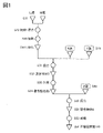
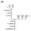
- a composite oxide containing lithium and cobalt is mixed with a barium source, a magnesium source, and a fluorine source to form a first composite oxide containing barium fluoride, magnesium fluoride, and lithium fluoride.
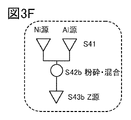
- a step of preparing a mixture a step of heating the first mixture at a temperature of 800° C. or higher and 1100° C. or lower for 2 hours or more, mixing the first mixture with a nickel source and an aluminum source, 2, and heating the second mixture at a temperature of 800 ° C. or higher and 1100 ° C.
- a composite oxide containing lithium and cobalt is mixed with a barium source, a magnesium source, and a fluorine source to obtain a second compound containing barium fluoride, magnesium fluoride, and lithium fluoride.
- a step of preparing a mixture of 1 a step of heating the first mixture at a temperature of 800° C. or more and 1100° C. or less for 2 hours or more, and mixing the first mixture with a nickel source and an aluminum source.
- Another aspect of the present invention is a positive electrode having a positive electrode active material produced using the method for producing a positive electrode active material according to any one of the above.
- Another aspect of the present invention is a lithium ion secondary battery having a negative electrode, an electrolyte, and the positive electrode described above.
- the negative electrode preferably contains a carbonaceous material.
- the electrolyte preferably has a solid electrolyte.
- Another aspect of the present invention is a moving body having the lithium-ion secondary battery according to any one of the above.
- Another aspect of the present invention is a power storage system having the lithium ion secondary battery according to any one of the above.
- Another aspect of the present invention is an electronic device having the lithium ion secondary battery according to any one of the above.
- a method for manufacturing a positive electrode active material that is stable in a high potential state (also referred to as a high voltage charged state) and/or a high temperature state can be provided.
- a method for manufacturing a positive electrode active material with excellent charge-discharge cycle characteristics can be provided.
- a method for manufacturing a positive electrode active material with high charge-discharge capacity can be provided.
- one embodiment of the present invention can provide a method for manufacturing a highly reliable or safe secondary battery.
- one embodiment of the present invention can provide a positive electrode active material that is stable in a high potential state and/or a high temperature state.
- a positive electrode active material with excellent charge-discharge cycle characteristics.
- a positive electrode active material having a large charge/discharge capacity can be provided.
- a highly reliable or safe secondary battery can be provided.
- one embodiment of the present invention can provide novel substances, active material particles, electrodes, secondary batteries, power storage devices, or manufacturing methods thereof. Further, one embodiment of the present invention can provide a method for manufacturing a secondary battery or a secondary battery having one or more characteristics selected from high purity, high performance, and high reliability. .
- FIG. 1 is a flowchart showing steps for manufacturing a positive electrode active material which is one embodiment of the present invention.
- FIG. 2 is a flowchart showing steps for manufacturing a positive electrode active material which is one embodiment of the present invention.
- 3A to 3F are flowcharts showing steps for manufacturing a positive electrode active material which is one embodiment of the present invention.
- 4A1 to 4C2 are cross-sectional views of positive electrode active materials.
- FIG. 5 illustrates the charge depth and crystal structure of the positive electrode active material of one embodiment of the present invention.
- FIG. 6 is an XRD pattern calculated from the crystal structure.
- FIG. 7 is a diagram for explaining the charge depth and crystal structure of the positive electrode active material of the comparative example.
- FIG. 8 is an XRD pattern calculated from the crystal structure.
- FIG. 9A is an exploded perspective view of the coin-type secondary battery
- FIG. 9B is a perspective view of the coin-type secondary battery
- FIG. 9C is a cross-sectional perspective view thereof.
- FIG. 10A shows an example of a cylindrical secondary battery.
- FIG. 10B shows an example of a cylindrical secondary battery.
- FIG. 10C shows an example of a plurality of cylindrical secondary batteries.
- FIG. 10D shows an example of a power storage system having a plurality of cylindrical secondary batteries.
- 11A and 11B are diagrams for explaining an example of a secondary battery
- FIG. 11C is a diagram showing the state inside the secondary battery.
- 12A to 12C are diagrams illustrating examples of secondary batteries.
- 13A and 13B are diagrams showing the appearance of a secondary battery.
- 14A to 14C are diagrams illustrating a method for manufacturing a secondary battery.
- 15A to 15C are diagrams showing configuration examples of battery packs.
- 16A and 16B are cross-sectional views of active material layers when a graphene compound is used as a conductive material.
- 17A and 17B are diagrams illustrating an example of a secondary battery.
- 18A to 18C are diagrams illustrating examples of secondary batteries.
- 19A and 19B are diagrams illustrating an example of a secondary battery.
- 20A is a perspective view of a battery pack showing one embodiment of the present invention
- FIG. 20B is a block diagram of the battery pack
- FIG. 20C is a block diagram of a vehicle having a motor.
- 21A to 21E are diagrams illustrating an example of a moving object.
- FIG. 22A and 22B are diagrams illustrating a power storage device according to one embodiment of the present invention.
- 23A is a diagram showing an electric bicycle
- FIG. 23B is a diagram showing a secondary battery of the electric bicycle
- FIG. 23C is a diagram explaining an electric motorcycle.
- 24A to 24D are diagrams illustrating examples of electronic devices.
- FIG. 25A shows an example of a wearable device
- FIG. 25B shows a perspective view of a wristwatch-type device
- FIG. 25C is a diagram illustrating a side view of the wristwatch-type device.
- FIG. 25D is a diagram illustrating an example of a wireless earphone.
- Figures 26A and 26B are SEM images of the example.
- 27A and 27B are SEM images of the example.
- Figures 28A and 28B are SEM images of the example.
- 29A and 29B are graphs showing the cycle characteristics of the half-cell of Example.
- composite oxide refers to an oxide containing multiple types of metal elements in its structure.
- crystal planes and directions are indicated by Miller indices. Crystallographic planes and orientations are represented by a bar above the numbers in terms of crystallography. ) may be attached.
- individual orientations that indicate directions within the crystal are [ ]
- collective orientations that indicate all equivalent directions are ⁇ >
- individual planes that indicate crystal planes are ( )
- collective planes that have equivalent symmetry are ⁇ ⁇ to express each.
- (hkil) as well as (hkl) may be used for the Miller indices of trigonal and hexagonal crystals such as R-3m. where i is -(h+k).
- the layered rock salt type crystal structure of a composite oxide containing lithium and a transition metal has a rock salt type ion arrangement in which cations and anions are alternately arranged, and the transition metal and It refers to a crystal structure in which lithium can be diffused two-dimensionally because each lithium is regularly arranged to form a two-dimensional plane.
- the layered rock salt type crystal structure may be a structure in which the lattice of the rock salt type crystal is distorted.
- a rock salt-type crystal structure refers to a structure in which cations and anions are arranged alternately. A part of the crystal structure may have a defect of cations or anions.
- the active material is sometimes referred to as active material particles, but there are various shapes, and the shape is not limited to particles.
- the shape of the active material (active material particles) in one cross section may be elliptical, rectangular, trapezoidal, triangular, square with rounded corners, or asymmetrical in addition to circular.
- the smooth state of the surface of the active material can be said to have a surface roughness of at least 10 nm or less when surface unevenness information is quantified from measurement data in one cross section of the active material.
- one cross section is a cross section obtained when observing with a scanning transmission electron microscope (STEM), for example.
- STEM scanning transmission electron microscope
- the theoretical capacity of the positive electrode active material is the amount of electricity when all of the lithium that can be intercalated and desorbed from the positive electrode active material is desorbed.
- LiCoO 2 has a theoretical capacity of 274 mAh/g
- LiNiO 2 has a theoretical capacity of 275 mAh/g
- LiMn 2 O 4 has a theoretical capacity of 148 mAh/g.
- the amount of lithium that can be intercalated and deintercalated remaining in the positive electrode active material is indicated by x in the composition formula, for example, x in Li x CoO 2 or x in Li x MO 2 (M is a transition metal element).
- Li x CoO 2 in this specification can be appropriately read as Li x MO 2 .
- x (theoretical capacity ⁇ charge capacity)/theoretical capacity.
- Li 0.2 CoO 2 or x 0.2.
- a small x in Li x CoO 2 means, for example, 0.1 ⁇ x ⁇ 0.24.
- the term “discharging is completed” refers to a state in which the voltage becomes 2.5 V (counter electrode lithium) or less at a current of 100 mA/g, for example.
- the discharge voltage drops sharply before the discharge voltage reaches 2.5 V, so assume that the discharge is terminated under the above conditions.
- the charge capacity and/or discharge capacity used to calculate x in Li x CoO 2 is preferably measured under conditions where there is no or little influence of short circuit and/or decomposition of the electrolyte.
- the data of a secondary battery in which a sudden change in capacity, which is thought to be caused by a short circuit, has occurred should not be used for calculating x.
- Step S11 a lithium source (Li source) and a transition metal source (M source) are respectively prepared as starting materials of lithium and transition metal.
- the lithium source it is preferable to use a compound containing lithium.
- a compound containing lithium for example, lithium carbonate, lithium hydroxide, lithium nitrate, or lithium fluoride can be used.
- the lithium source preferably has a high purity, and for example, a material with a purity of 99.99% or higher is preferably used.
- the transition metal can be selected from elements listed in Groups 3 to 11 of the periodic table, and at least one of manganese, cobalt, and nickel is used, for example.
- the transition metal only cobalt is used, only nickel is used, two kinds of cobalt and manganese are used, two kinds of cobalt and nickel are used, or three kinds of cobalt, manganese and nickel are used. be.
- the resulting positive electrode active material has lithium cobalt oxide (LCO), and when cobalt, manganese, and nickel are used, the resulting positive electrode active material is nickel-cobalt-lithium manganate (NCM ).
- the transition metal source it is preferable to use a compound containing the transition metal.
- oxides or hydroxides of the metals exemplified as the transition metals can be used.
- Cobalt oxide, cobalt hydroxide, and the like can be used as the cobalt source.
- Manganese oxide, manganese hydroxide, or the like can be used as a manganese source.
- nickel source nickel oxide, nickel hydroxide, or the like can be used.
- aluminum source aluminum oxide, aluminum hydroxide, or the like can be used.
- the transition metal source has a high purity. 99.999%) or higher is preferably used. Impurities in the positive electrode active material can be controlled by using a high-purity material. As a result, the capacity of the secondary battery is increased and/or the reliability of the secondary battery is improved.
- the transition metal source has high crystallinity, for example, it should have single crystal grains.
- TEM transmission electron microscope
- STEM scanning transmission electron microscope
- HAADF-STEM high angle scattering annular dark field scanning transmission electron microscope
- ABF-STEM annular dark field scanning transmission electron microscope
- XRD X-ray diffraction
- the method for evaluating the crystallinity described above can be applied not only to the transition metal source but also to the evaluation of other crystallinity.
- the two or more transition metal sources when two or more transition metal sources are used, it is preferable to prepare the two or more transition metal sources in such a ratio (mixing ratio) that the resulting composite oxide can have a layered rock salt crystal structure.
- Step S12 the lithium source and the transition metal source are pulverized and mixed to produce a mixed material. Grinding and mixing can be dry or wet. The wet method is preferred because it can be pulverized into smaller pieces.
- a solvent if the method is wet. Examples of solvents that can be used include ketones such as acetone, alcohols such as ethanol and isopropanol, ethers, dioxane, acetonitrile, and N-methyl-2-pyrrolidone (NMP). It is more preferable to use an aprotic solvent that is less likely to react with lithium. In this embodiment, dehydrated acetone with a purity of 99.5% or higher is used.
- the lithium source and the transition metal source are mixed with dehydrated acetone with a purity of 99.5% or more and with a water content of 10 ppm or less, followed by pulverization and mixing.
- dehydrated acetone with the above purity, possible impurities can be reduced.
- a ball mill, bead mill, or the like can be used for mixing.
- a ball mill it is preferable to use alumina balls or zirconia balls as grinding media. Zirconia balls are preferable because they emit less impurities.
- the peripheral speed should be 100 mm/s or more and 2000 mm/s or less in order to suppress contamination from the media. In this embodiment, the peripheral speed is 838 mm/s (rotational speed: 400 rpm, ball mill diameter: 40 mm).
- step S13 shown in FIG. 1 the mixed material is heated.
- This step may be referred to as firing or first heating in order to distinguish it from the subsequent heating step.
- the heating temperature is preferably 700° C. or higher and 1200° C. or lower, more preferably 800° C. or higher and 1100° C. or lower.
- the heating temperature is more preferably 900°C or higher and 1000°C or lower, more preferably about 950°C.
- the temperature is preferably 1000° C. or higher and 1200° C. or lower. If the temperature is too low, decomposition and melting of the lithium source and transition metal source may be insufficient.
- the heating time is preferably 1 hour or more and 100 hours or less, preferably 2 hours or more and 20 hours or less.
- the rate of temperature increase depends on the temperature reached by the heating temperature, but is preferably 80°C/h or more and 250°C/h or less. For example, when heating at 1000° C. for 10 hours, the temperature should be raised at 200° C./h.
- Heating is preferably carried out in an atmosphere with little water such as dry air, for example, an atmosphere with a dew point of -50°C or lower, more preferably -80°C or lower. In this embodiment mode, heating is performed in an atmosphere with a dew point of -93°C. Further, in order to suppress impurities that may be mixed into the material, the concentrations of impurities such as CH 4 , CO, CO 2 and H 2 in the heating atmosphere should each be 5 ppb (parts per billion) or less.
- An atmosphere containing oxygen is preferable as the heating atmosphere.
- the heating atmosphere there is a method of continuously introducing dry air into the reaction chamber.
- the flow rate of dry air is preferably 2 L/min or more and 10 L/min or less.
- the process by which oxygen is continuously supplied to the reaction chamber and is flowing through the reaction chamber is called flow.
- the heating atmosphere is an atmosphere containing oxygen
- a method in which oxygen is not supplied to the reaction chamber may be used.
- the reaction chamber may be decompressed and then filled with oxygen to prevent the oxygen from entering or exiting the reaction chamber. This is called purging.
- the pressure in the reaction chamber is controlled by a differential pressure gauge, the pressure is reduced to -970 hPa and then oxygen is filled up to 50 hPa.
- Cooling after heating may be natural cooling, but it is preferable if the cooling time from the specified temperature to room temperature is within 10 hours or more and 50 hours or less. However, cooling to room temperature is not necessarily required, and cooling to a temperature that the next step allows is sufficient.
- Heating in this process may be performed by a rotary kiln or a roller hearth kiln. Heating by a rotary kiln can be performed while stirring in either a continuous system or a batch system.
- a crucible can be used as a container for heating, and the material of the container is preferably alumina.
- Alumina crucible is a material that does not easily release impurities. In this embodiment, an alumina crucible with a purity of 99.9% is used. It is preferable to place a lid on the crucible and heat it. Evaporation or sublimation of materials can be prevented.
- a flat-bottomed container called a pod or setter may be used instead of the crucible.
- Mullite Al 2 O 3 —SiO 2 ceramics
- Alumina mortar is a material that does not easily release impurities. Specifically, an alumina mortar with a purity of 90% or higher, preferably 99% or higher is used. Note that the same heating conditions as in step S13 can be applied to the later-described heating process other than step S13.
- a composite oxide (LiMO 2 ) having a transition metal can be obtained in step S14 shown in FIG.
- cobalt for example lithium cobaltate can be obtained, denoted LiCoO 2 .
- a composite oxide may be produced by a coprecipitation method.
- a composite oxide may also be produced by a hydrothermal method.
- step S19 the additive element X and the additive element Y may be added to the composite oxide to the extent that a layered rock salt type crystal structure can be obtained. Details of the step of obtaining the additive element X source (X source) and the step of obtaining the additive element Y source (Y source) shown in FIG. 1 will be described with reference to FIGS. 3A to 3D.
- step S22 shown in FIG. 3A an X source to be added to the composite oxide is prepared.
- the additive element X is barium (Ba)
- a barium source (Ba source) can be prepared as the X source.
- a fluorine source (F source) may also be included.
- FIG. 3A shows an example in which a Ba source and an F source are prepared in step S22.
- Ba source for example, barium fluoride (BaF 2 ), barium oxide (BaO), barium hydroxide (Ba(OH) 2 ), barium nitrate (Ba(NO 3 ) 2 ), barium sulfate (BaSO 4 ) or barium carbonate (BaCO 3 ) and the like can be used.
- BaF 2 barium fluoride
- BaO barium oxide
- Ba(OH) 2 barium hydroxide
- Ba(NO 3 ) 2 barium nitrate
- BaSO 4 barium sulfate
- BaCO 3 barium carbonate
- F sources include lithium fluoride (LiF), magnesium fluoride ( MgF2 ), aluminum fluoride ( AlF3 ), titanium fluoride ( TiF4 ), cobalt fluoride ( CoF2 , CoF3 ), and nickel fluoride.
- lithium fluoride is preferable because it has a relatively low melting point of 848° C. and is easily melted in a heating step to be described later.
- Ba source and an F source As the X source, it is preferable to use barium fluoride as the Ba source and lithium fluoride as the F source because they have a eutectic point.
- the Ba source and F source prepared in step S22 are pulverized.
- the Ba source and the F source may be pulverized independently as shown in step S23a of FIG. 3A, or pulverized while mixing the Ba source and the F source as shown in step S23b of FIG. 3B. good too.
- Pulverization or pulverization and mixing can be performed by selecting from the pulverization and mixing conditions described in step S12 of FIG.
- pulverization for the X source may not be performed.
- Step S24a/S24b the above pulverized or pulverized and mixed material can be recovered to obtain the X source.
- an X source with multiple starting materials can be referred to as a mixture.
- Either the step shown in FIG. 3A or the step shown in FIG. 3B may be adopted as the step of obtaining the X source.
- Step S25 a Y source to be added to the composite oxide is prepared. It is desirable to further have a fluorine source (F source) as the Y source.
- F source fluorine source
- 3C and 3D show an example of preparing a magnesium source (Mg source) and a fluorine source (F source) in step S25.
- the additive element Y is selected from magnesium, calcium, fluorine, aluminum, nickel, cobalt, manganese, titanium, zirconium, yttrium, vanadium, chromium, niobium, lanthanum, hafnium, zinc, silicon, sulfur, phosphorus, and boron. can be used.
- the Y source can be called a magnesium source.
- Magnesium fluoride, magnesium oxide, magnesium hydroxide, magnesium carbonate, or the like can be used as the magnesium source.
- the Y source can be called a fluorine source.
- the fluorine source include lithium fluoride (LiF), magnesium fluoride (MgF 2 ), aluminum fluoride (AlF 3 ), titanium fluoride (TiF 4 ), cobalt fluoride (CoF 2 , CoF 3 ) and fluorine.
- Magnesium fluoride can be used as both a fluorine source and a magnesium source.
- Lithium fluoride can also be used as a lithium source.
- the fluorine source may also be gaseous, such as fluorine ( F2), carbon fluoride, sulfur fluoride, or oxygen fluoride ( OF2 , O2F2 , O3F2 , O4F2 , O2F ). may be used and mixed in the atmosphere in the heating step described later. Also, a plurality of fluorine sources as described above may be used.
- lithium fluoride (LiF) is prepared as the fluorine source
- magnesium fluoride (MgF 2 ) is prepared as the magnesium source.
- the amount of lithium fluoride increases, there is a concern that the amount of lithium becomes excessive and the cycle characteristics deteriorate.
- the term “near” means a value larger than 0.9 times and smaller than 1.1 times the value.
- Either the step shown in FIG. 3C or the step shown in FIG. 3D may be adopted as the step of obtaining the Y source.
- 3 ⁇ y ⁇ 10 and 4 ⁇ z ⁇ 7, more preferably 3 ⁇ y ⁇ 5 and 4 ⁇ z ⁇ 4.6 are expected to improve battery characteristics. It is preferable because it can be done.
- the effect of lowering the heating temperature in step S33, which will be described later, can be expected.
- Step S26a/S26b> the Mg source and F source prepared in step S25 are pulverized.
- the Mg source and F source may be pulverized independently as shown in step S26a of FIG. 3C, or the Mg source and F source may be mixed and pulverized as shown in step S26b of FIG. 3D. good too.
- Pulverization or pulverization and mixing can be performed by selecting from the pulverization and mixing conditions described in step S12 of FIG.
- a heating process may be performed after step S26b if necessary.
- the heating process can be performed by selecting from the heating conditions described in step S13.
- the heating time is preferably 2 hours or longer, and the heating temperature is preferably 800° C. or higher and 1100° C. or lower.
- Step S27a/S27b the above pulverized or pulverized and mixed material can be recovered to obtain the Y source.
- a Y source with multiple starting materials can be referred to as a mixture.
- the particle diameters of the mixture in step S24a or step S24b and the mixture in step S27a or step S27b preferably have a D50 (median diameter) of 50 nm or more and 10 ⁇ m or less, more preferably 100 nm or more and 3 ⁇ m or less. Even when one kind of material is used as the additive element source, the D50 (median diameter) is preferably 50 nm or more and 10 ⁇ m or less, more preferably 100 nm or more and 3 ⁇ m or less.
- Such a finely divided mixture allows the mixture to uniformly adhere to the surfaces of the particles of the composite oxide when mixed with the composite oxide in a later step.
- Cheap When the mixture is uniformly adhered to the surface of the composite oxide, it is preferable because barium and magnesium are easily distributed or diffused uniformly in the surface layer of the composite oxide after heating. A region in which barium and magnesium are distributed can also be called a surface layer portion. If there is a region that does not contain barium and magnesium in the surface layer, it may be difficult to form an O3'-type crystal structure, which will be described later, in the charged state.
- step S31 Next, in step S31 shown in FIG. 1, the composite oxide, the X source, and the Y source are mixed.
- the mixing in step S31 is preferably under milder conditions than the mixing in step S12 so as not to destroy the particles of the composite oxide.
- the number of revolutions is smaller or the time is shorter than the mixing in step S12.
- the conditions for the dry method are milder than those for the wet method.
- a ball mill, bead mill, kneader, or the like can be used.
- zirconia balls as media.
- the mixing is performed in a dry room with a dew point of -100°C or higher and -10°C or lower.
- step S32 of FIG. 1 the mixed materials are recovered to obtain a mixture 903.
- the molar ratio of barium fluoride (BaF 2 ) contained in the additive element X in step S19 and magnesium fluoride (MgF 2 ) contained in the additive element Y is maintained. Further, in the mixture 903, the molar ratio of the lithium fluoride (LiF) contained in the additional element X and the additional element Y in step S19 and the barium fluoride (BaF 2 ) contained in the additional element X is maintained.
- step S33 shown in FIG. 1 the mixture 903 is heated. It can be implemented by selecting from the heating temperatures described in step S13.
- the heating time is preferably 2 hours or more. This step may be referred to as second heating.
- the heating temperature is supplemented here.
- the lower limit of the heating temperature in step S33 needs to be higher than or equal to the temperature at which the reaction between the composite oxide (LiMO 2 ) and the X and Y sources proceeds.
- the temperature at which the reaction proceeds may be any temperature at which interdiffusion of the elements of LiMO 2 and the X source and Y source occurs, and may be lower than the melting temperature of these materials. Taking oxides as an example, it is known that solid-phase diffusion occurs from 0.757 times the melting temperature T m (Tammann temperature T d ). Therefore, the heating temperature in step S33 may be 500° C. or higher.
- the reaction proceeds more easily.
- the eutectic point of LiF and BaF 2 is around 765° C.
- the lower limit of the heating temperature in step S33 is preferably 765° C. or higher.
- the eutectic point of LiF and MgF 2 is around 742° C., so the lower limit of the heating temperature in step S33 is preferably 742° C. or higher.
- the heating temperature in step S33 is preferably 654° C. or higher, more preferably 742° C. or higher, and more preferably 775° C. or higher.
- the upper limit of the heating temperature is less than the decomposition temperature of LiMO 2 (the decomposition temperature of LiCoO 2 is 1130° C.). At temperatures near the decomposition temperature, there is concern that LiMO 2 will decompose, albeit in a very small amount. Therefore, it is more preferably 1000° C. or lower, more preferably 950° C. or lower, and even more preferably 900° C. or lower.
- the heating temperature in step S33 is preferably 500° C. or higher and 1130° C. or lower, more preferably 500° C. or higher and 1000° C. or lower, even more preferably 500° C. or higher and 950° C. or lower, and further preferably 500° C. or higher and 900° C. or lower. preferable.
- the temperature is preferably 654°C or higher and 1130°C or lower, more preferably 654°C or higher and 1000°C or lower, even more preferably 654°C or higher and 950°C or lower, and even more preferably 654°C or higher and 900°C or lower.
- the temperature is preferably 742°C or higher and 1130°C or lower, more preferably 742°C or higher and 1000°C or lower, even more preferably 742°C or higher and 950°C or lower, and even more preferably 742°C or higher and 900°C or lower.
- the temperature is preferably 765°C or higher and 1130°C or lower, more preferably 765°C or higher and 1000°C or lower, even more preferably 765°C or higher and 950°C or lower, and even more preferably 765°C or higher and 900°C or lower.
- the heating temperature in step S33 is preferably lower than that in step S13.
- the mixture 903 when the mixture 903 is heated, it is preferable to control the partial pressure of fluorine or fluoride caused by the fluorine source or the like in a heating furnace or a heating vessel such as a crucible within an appropriate range.
- some materials such as LiF, which is a lithium source, function as a flux in some cases.
- the heating temperature can be lowered to below the decomposition temperature of the composite oxide (LiMO 2 ), for example, 654 ° C. or higher and 950 ° C. or lower. of the positive electrode active material can be produced.
- LiF has a lower specific gravity than oxygen in a gaseous state
- LiF may evaporate or sublime by heating, and the evaporation or sublimation reduces LiF in the mixture 903 .
- the function as a flux is weakened. Therefore, it is necessary to perform heating while suppressing evaporation or sublimation of LiF.
- LiF is not used as a lithium source or the like, there is a possibility that Li on the surface of LiMO 2 reacts with F in the fluorine source to generate LiF, which evaporates or sublimes. Therefore, even if a fluoride having a higher melting point than LiF is used, it is necessary to similarly suppress evaporation or sublimation.
- the mixture 903 in an atmosphere containing LiF, that is, to heat the mixture 903 in a state where the partial pressure of LiF in the heating furnace is high.
- Such heating can suppress transpiration or sublimation of LiF in the mixture 903 .
- the heating in this step is preferably performed so that the particles of the mixture 903 do not adhere to each other. If the particles of the mixture 903 adhere to each other during heating, the contact area with oxygen in the atmosphere is reduced, and the diffusion path of the additive element X and the additive element Y (for example, barium, magnesium, and fluorine) is inhibited.
- the additional element X and the additional element Y may not be uniformly distributed in the part. Therefore, in order to make the surface smooth in this step, it is better that the particles do not adhere to each other.
- the additive element X and the additive element Y are uniformly distributed on the surface layer, a positive electrode active material that is smooth and has few irregularities can be obtained. Therefore, in order to maintain or smoothen the surface after the heating in step S13 in this step, it is preferable that the particles do not adhere to each other.
- the flow rate of the oxygen-containing atmosphere in the kiln when heating with a rotary kiln, it is preferable to control the flow rate of the oxygen-containing atmosphere in the kiln. For example, it is preferable to reduce the flow rate of the oxygen-containing atmosphere, to purge the atmosphere first and not to supply oxygen after introducing the oxygen atmosphere into the kiln, and the like. If oxygen is supplied and oxygen flows in the above atmosphere, the fluorine source may evaporate or sublimate, which is not preferable for making the surface smooth.
- the mixture 903 can be heated in an atmosphere containing LiF, for example, by placing a lid on the container containing the mixture 903 .
- the heating time varies depending on conditions such as the heating temperature, the particle size of LiMO 2 in step S14, and the composition. Lower temperatures or shorter times may be preferred for smaller particles than for larger particles.
- the heating temperature is preferably 600° C. or higher and 950° C. or lower, for example.
- the heating time is, for example, preferably 3 hours or longer, more preferably 10 hours or longer, and even more preferably 60 hours or longer.
- the cooling time after heating is, for example, 10 hours or more and 50 hours or less.
- the heating temperature is preferably 600° C. or higher and 950° C. or lower.
- the heating time is, for example, preferably 1 hour or more and 10 hours or less, more preferably about 2 hours.
- the cooling time after heating is, for example, 10 hours or more and 50 hours or less.
- Step S34> the material heated in step S33 is recovered to obtain a composite oxide containing the additive element X and the additive element Y.
- FIG. It is also called a second composite oxide to distinguish it from the composite oxide in step S14.
- step S40 shown in FIG. 1 an additive element Z source is added.
- An example of using nickel and aluminum as the additive element Z will be described with reference to FIGS. 3E and 3F.
- the additive element Z is selected from magnesium, calcium, fluorine, aluminum, nickel, cobalt, manganese, titanium, zirconium, yttrium, vanadium, chromium, niobium, lanthanum, hafnium, zinc, silicon, sulfur, phosphorus, and boron. can be used.
- nickel and aluminum are selected as the additive element Z
- nickel oxide, nickel hydroxide, etc. can be used as the nickel source.
- Aluminum oxide, aluminum hydroxide, and the like can be used as the aluminum source.
- Step S41 In step S41 shown in FIGS. 3E and 3F, a nickel source (Ni source) and an aluminum source (Al source) are prepared.
- Ni source Ni source
- Al source aluminum source
- Step S42a/S42b> the Ni source and Al source prepared in step S41 are pulverized.
- the Ni source and the Al source may be pulverized independently as shown in step S42a of FIG. 3E, or the Ni source and the Al source are mixed and pulverized as shown in step S42b of FIG. 3F. good too.
- Step S43a/S43b > Next, in step S43a shown in FIG. 3E or step S43b shown in FIG. 3F, the above pulverized or pulverized and mixed material can be recovered to obtain the additive element Z source (Z source).
- Z source additive element Z source
- Either the step shown in FIG. 3E or the step shown in FIG. 3F may be adopted as the step of obtaining the additive element Z source.
- steps S51 to S53 shown in FIG. 1 can be manufactured under the same conditions as steps S31 to S34.
- the mixture 904 of step S52 is heated in step S53.
- the heating conditions in step S53 may be a lower temperature and a shorter time than in step S33.
- the heating in step S53 may be referred to as third heating.
- ⁇ Preparation method 2 of positive electrode active material>> A method for manufacturing a positive electrode active material, which is another embodiment of the present invention, will be described with reference to FIGS. Steps S11 to S14 can be performed in the same manner as described in ⁇ Method 1 for Producing Positive Electrode Active Material>>.
- Additional element X, additional element Y, and additional element Z may be added to the composite oxide obtained in step S14 to the extent that a layered rock salt type crystal structure can be obtained.
- the additive element X, the additive element Y, and the additive element Z are added to the composite oxide at the same time.
- the step of obtaining the additive element X source and the step of obtaining the additive element Y source can be performed in the same manner as described in ⁇ Positive electrode active material manufacturing method 1>>.
- Either the step shown in FIG. 3A or the step shown in FIG. 3B may be adopted as the step of obtaining the additive element X source.
- Either the step shown in FIG. 3C or the step shown in FIG. 3D may be adopted as the step of obtaining the additive element Y source.
- the step of obtaining the additive element Z source shown in FIG. 2 can be performed in the same manner as the step of obtaining the additive element Z source described in ⁇ Positive electrode active material manufacturing method 1>>. Either the step shown in FIG. 3E or the step shown in FIG. 3F may be adopted as the step of obtaining the additive element Z source.
- the molar ratio of barium fluoride (BaF 2 ) contained in the additive element X source in S19 and magnesium fluoride (MgF 2 ) contained in the additive element Y source and the fluoride contained in the additive element Y in step S19 The molar ratio between lithium (LiF) and barium fluoride (BaF 2 ) contained in the additive element X may be set in the same manner as described in ⁇ Method 1 for Preparing Positive Electrode Active Material>>.
- step S31 Next, in step S31 shown in FIG. 2, the composite oxide, the X source, the Y source, and the Z source are mixed.
- the mixing in step S31 is preferably under milder conditions than the mixing in step S12 so as not to destroy the particles of the composite oxide.
- the number of revolutions is smaller or the time is shorter than the mixing in step S12.
- the conditions for the dry method are milder than those for the wet method.
- a ball mill, bead mill, kneader, or the like can be used.
- zirconia balls as media.
- the mixing is performed in a dry room with a dew point of -100°C or higher and -10°C or lower.
- step S32 of FIG. 2 the mixed materials are recovered to obtain a mixture 905.
- step S33 the mixture 905 is heated. It can be implemented by selecting from the heating temperatures described in step S13.
- the heating time is preferably 2 hours or more.
- the heating temperature is supplemented here.
- the lower limit of the heating temperature in step S33 needs to be higher than or equal to the temperature at which the reaction between the composite oxide (LiMO 2 ) and the X, Y and Z sources proceeds.
- the temperature at which the reaction proceeds may be any temperature at which interdiffusion of elements of LiMO 2 and the X source, Y source, and Z source occurs, and may be lower than the melting temperature of these materials. Taking oxides as an example, it is known that solid-phase diffusion occurs from 0.757 times the melting temperature T m (Tamman temperature T d ). Therefore, the heating temperature in step S33 may be 500° C. or higher.
- the reaction proceeds more easily.
- the eutectic point of LiF and BaF 2 is around 765° C.
- the lower limit of the heating temperature in step S33 is preferably 765° C. or higher.
- the eutectic point of LiF and MgF 2 is around 742° C., so the lower limit of the heating temperature in step S33 is preferably 742° C. or higher.
- the heating temperature in step S33 is preferably 654° C. or higher, more preferably 742° C. or higher, and more preferably 775° C. or higher.
- the upper limit of the heating temperature is less than the decomposition temperature of LiMO 2 (the decomposition temperature of LiCoO 2 is 1130° C.). At temperatures near the decomposition temperature, there is concern that LiMO 2 will decompose, albeit in a very small amount. Therefore, it is more preferably 1000° C. or lower, more preferably 950° C. or lower, and even more preferably 900° C. or lower.
- the heating temperature in step S33 is preferably 500° C. or higher and 1130° C. or lower, more preferably 500° C. or higher and 1000° C. or lower, even more preferably 500° C. or higher and 950° C. or lower, and further preferably 500° C. or higher and 900° C. or lower. preferable.
- the temperature is preferably 654°C or higher and 1130°C or lower, more preferably 654°C or higher and 1000°C or lower, even more preferably 654°C or higher and 950°C or lower, and even more preferably 654°C or higher and 900°C or lower.
- the temperature is preferably 742°C or higher and 1130°C or lower, more preferably 742°C or higher and 1000°C or lower, even more preferably 742°C or higher and 950°C or lower, and even more preferably 742°C or higher and 900°C or lower.
- the temperature is preferably 765°C or higher and 1130°C or lower, more preferably 765°C or higher and 1000°C or lower, even more preferably 765°C or higher and 950°C or lower, and even more preferably 765°C or higher and 900°C or lower.
- the mixture 905 when the mixture 905 is heated, it is preferable to control the partial pressure of fluorine or fluoride caused by the fluorine source or the like in the heating furnace or the heating vessel such as the crucible within an appropriate range.
- some materials such as LiF, which is a Li source, may function as a flux.
- the heating temperature can be lowered to below the decomposition temperature of the composite oxide (LiMO 2 ), for example, 654 ° C. or higher and 950 ° C. or lower. of the positive electrode active material can be produced.
- LiF has a lower specific gravity than oxygen in a gaseous state
- LiF may evaporate or sublime by heating, and the evaporation or sublimation reduces LiF in the mixture 905 .
- the function as a flux is weakened. Therefore, it is necessary to perform heating while suppressing evaporation or sublimation of LiF.
- LiF is not used as a lithium source or the like, there is a possibility that Li on the surface of LiMO 2 reacts with F in the fluorine source to generate LiF, which evaporates or sublimes. Therefore, even if a fluoride having a higher melting point than LiF is used, it is necessary to similarly suppress evaporation or sublimation.
- the mixture 905 in an atmosphere containing LiF, that is, to heat the mixture 905 in a state where the partial pressure of LiF in the heating furnace is high.
- Such heating can suppress transpiration or sublimation of LiF in the mixture 905 .
- the heating in this step is preferably performed so that the particles of the mixture 905 do not adhere to each other. If the particles of the mixture 905 adhere to each other during heating, the contact area with oxygen in the atmosphere is reduced, and the diffusion path of the additive element X and the additive element Y (for example, barium, magnesium, and fluorine) is inhibited.
- the additional element X and the additional element Y may not be uniformly distributed in the part. Therefore, in order to make the surface smooth in this step, it is better that the particles do not adhere to each other.
- additive element X and the additive element Y are uniformly distributed on the surface layer, a positive electrode active material that is smooth and has few irregularities can be obtained.
- the flow rate of the oxygen-containing atmosphere in the kiln when heating with a rotary kiln, it is preferable to control the flow rate of the oxygen-containing atmosphere in the kiln. For example, it is preferable to reduce the flow rate of the oxygen-containing atmosphere, to purge the atmosphere first and not to supply oxygen after introducing the oxygen atmosphere into the kiln, and the like. If oxygen is supplied and oxygen flows in the above atmosphere, the fluorine source may evaporate or sublimate, which is not preferable for making the surface smooth.
- the mixture 905 can be heated in an atmosphere containing LiF, for example, by placing a lid on the container containing the mixture 905 .
- the heating time varies depending on conditions such as the heating temperature, the particle size of LiMO 2 in step S14, and the composition. Lower temperatures or shorter times may be preferred for smaller particles than for larger particles.
- the heating temperature is preferably 600° C. or higher and 950° C. or lower, for example.
- the heating time is, for example, preferably 3 hours or longer, more preferably 10 hours or longer, and even more preferably 60 hours or longer.
- the cooling time after heating is, for example, 10 hours or more and 50 hours or less.
- the heating temperature is preferably 600° C. or higher and 950° C. or lower.
- the heating time is, for example, preferably 1 hour or more and 10 hours or less, more preferably about 2 hours.
- the cooling time after heating is, for example, 10 hours or more and 50 hours or less.
- Step S34> the material heated in step S ⁇ b>33 is recovered to obtain the positive electrode active material 100 .
- the F source was added as part of the X source and part of the Y source, but the F source may be added as either the X source or the Y source. good.
- the composite oxide When the composite oxide has cobalt as a transition metal, it can be read as a composite oxide containing cobalt.
- This embodiment can be used in combination with other embodiments.
- FIGS. 4A1 and 4A2 are cross-sectional views of the positive electrode active material 100 that is one embodiment of the present invention.
- FIGS. 4B1 and 4B2 show enlarged views of the vicinity of AB in FIG. 4A1.
- FIGS. 4C1 and 4C2 show enlarged views of the vicinity of CD in FIG. 4A1.
- the positive electrode active material 100 has a surface layer portion 100a and an inner portion 100b.
- the dashed line indicates the boundary between the surface layer portion 100a and the inner portion 100b.
- part of the grain boundary 101 is indicated by a dashed line.
- FIG. 4A2 also shows embedded portions 102 such as recesses, cracks, depressions, and V-shaped cross-sections that the positive electrode active material 100 has.
- 4A2 also shows the unevenly distributed portion 103.
- FIG. The unevenly distributed portion 103 is a region where the additive elements (additive element X, additive element Y, and/or additive element Z) of the positive electrode active material 100 are unevenly distributed.
- the surface layer portion 100a of the positive electrode active material 100 is, for example, within 50 nm from the surface toward the inside, more preferably within 35 nm from the surface toward the inside, and still more preferably within 20 nm from the surface toward the inside. It refers to a region within 10 nm, most preferably within 10 nm from the surface toward the inside. Surfaces caused by cracks and/or cracks may also be referred to as surfaces.
- the surface layer portion 100a may be referred to as a near-surface region or a near-surface region. A region deeper than the surface layer portion 100a of the positive electrode active material is called an inner portion 100b.
- the interior 100b may also be referred to as an interior region or the like.
- the concentration of additive elements (additional element X, additive element Y, and additive element Z) described later is preferably higher in the surface layer part 100a than in the inner part 100b. Further, the additive elements (additive element X, additive element Y, and additive element Z) preferably have a concentration gradient. When there are a plurality of additive elements (additive element X, additive element Y, and additive element Z), it is preferable that the depth of the concentration peak from the surface differs depending on the additive element.
- the additive element X and the additive element Y preferably have a concentration gradient that increases from the inside 100b toward the surface, as shown by the gradation in FIG. 4B1.
- Examples of additive element X and additive element Y that preferably have such a concentration gradient include barium, magnesium, fluorine, titanium, silicon, phosphorus, boron, and calcium.
- Another additive element Z preferably has a concentration gradient and a concentration peak in a region deeper than that in FIG. 4B1, as shown by the gradation in FIG. 4B2.
- the concentration peak may exist in the surface layer portion 100a or may be deeper than the surface layer portion 100a.
- the additive element Z preferably has a peak in the region of 5 nm or more and 50 nm or less from the surface toward the inside. Examples of additive elements Z that preferably have such a concentration gradient include aluminum and manganese.
- the crystal structure continuously changes from the inside 100b toward the surface. is preferred.
- the positive electrode active material 100 contains lithium, a transition metal M, oxygen, an additive element X, an additive element Y, and an additive element Z.
- the positive electrode active material 100 has a structure in which additive elements are added to a composite oxide represented by LiMO 2 .
- a positive electrode active material to which an additive element is added may also be called a composite oxide.
- the transition metal M contained in the positive electrode active material 100 it is preferable to use a metal capable of forming a layered rock salt-type composite oxide belonging to the space group R-3m together with lithium.
- a metal capable of forming a layered rock salt-type composite oxide belonging to the space group R-3m together with lithium For example, at least one of manganese, cobalt and nickel can be used. That is, as the transition metal M included in the positive electrode active material 100, only cobalt may be used, only nickel may be used, two kinds of cobalt and manganese, or two kinds of cobalt and nickel may be used, Cobalt, manganese, and nickel may be used.
- the positive electrode active material 100 includes lithium cobaltate, lithium nickelate, lithium cobaltate in which cobalt is partially replaced with manganese, lithium cobaltate in which cobalt is partially replaced by nickel, and nickel-manganese-lithium cobaltate. It can have a composite oxide containing lithium and transition metal M, such as.
- the layered rock salt type composite oxide has a two-dimensional lithium ion diffusion path and is suitable for the lithium ion insertion/extraction reaction.
- the transition metal M contained in the positive electrode active material 100 when 75 atomic % or more, preferably 90 atomic % or more, and more preferably 95 atomic % or more of cobalt is used as the transition metal M contained in the positive electrode active material 100, synthesis is relatively easy, handling is easy, and excellent cycle characteristics are obtained. and many other advantages. Further, if nickel is contained in addition to cobalt within the above range as the transition metal M, the shift of the layered structure composed of octahedrons of the transition metal and oxygen may be suppressed. Therefore, the crystal structure may become more stable particularly in a charged state at a high temperature, which is preferable.
- the transition metal M does not necessarily contain manganese.
- the weight of manganese contained in positive electrode active material 100 is preferably, for example, 600 ppm or less, more preferably 100 ppm or less.
- the raw material becomes cheaper than when cobalt is abundant. Also, the charge/discharge capacity per weight may increase, which is preferable.
- the transition metal M does not necessarily contain nickel.
- the weight of nickel contained in positive electrode active material 100 is, for example, 600 ppm or less, more preferably 100 ppm or less.
- additive elements included in the positive electrode active material 100 include barium, magnesium, fluorine, aluminum, titanium, zirconium, vanadium, iron, chromium, niobium, cobalt, arsenic, zinc, At least one of silicon, sulfur, phosphorus and boron is preferably used. These additive elements may further stabilize the crystal structure of the positive electrode active material 100 as described later.
- the positive electrode active material 100 includes lithium cobaltate to which barium, magnesium and fluorine are added, lithium cobaltate to which barium, magnesium and aluminum are added, nickel-lithium cobaltate to which barium, magnesium and fluorine are added, barium, Lithium cobalt-aluminate doped with magnesium and nickel, Lithium nickel-cobalt-aluminate, Lithium nickel-cobalt-aluminate doped with barium, magnesium and fluorine, Nickel-manganese doped with barium, magnesium and fluorine - Lithium cobaltate and the like.
- the additive element may also be referred to as a mixture, a part of raw materials, an impurity element, or the like.
- the additive elements do not necessarily include magnesium, fluorine, aluminum, titanium, zirconium, vanadium, iron, chromium, niobium, cobalt, arsenic, zinc, silicon, sulfur, phosphorus, or boron.
- the concentration of the additive element is high in the surface layer portion 100a.
- the concentration gradient of the additive elements (additional element X, additive element Y, and additive element Z) possessed by the positive electrode active material 100 is preferably the same across the entire surface layer portion 100a of the positive electrode active material 100. It can be said that it is preferable that the reinforcement derived from the high concentration of the additive element exists homogeneously in the surface layer portion 100a. Even if a part of the surface layer portion 100a is reinforced, if there is an unreinforced portion, stress may concentrate on the unreinforced portion. If the stress concentrates on a portion of the particles, defects such as cracks may occur there, leading to cracking of the positive electrode active material and a decrease in charge/discharge capacity.
- the term “homogeneous” refers to a phenomenon in which a certain element (eg, A) is distributed in a specific region with similar characteristics in a solid composed of multiple elements (eg, A, B, and C). Note that it is sufficient that the concentrations of the elements in the specific regions are substantially the same. For example, the difference in element concentration between specific regions may be within 10%. Specific regions include, for example, a surface layer portion, surface, convex portion, concave portion, inner portion, and the like.
- FIG. 4C1 shows an example of the distribution of additive element X and additive element Y near C-D in FIG. 4A1.
- FIG. 4C2 shows an example of distribution of the additional element Z near CD.
- the vicinity of C-D has a layered rock salt type crystal structure of R-3m, and the surface is (001) oriented.
- the (001) oriented surface may have a different distribution of additive elements (additive element X, additive element Y, and additive element Z) from other surfaces.
- additive element X, additive element Y, and additive element Z additive elements from other surfaces.
- the (001) oriented surface and its surface layer portion 100a may have a lower concentration of at least one of the additional element X, the additional element Y, and the additional element Z compared to other orientations.
- at least one of the additive element X, the additive element Y, and the additive element Z on the (001) oriented surface and its surface layer portion 100a may be below the detection limit.
- the (001) plane on which the MO 2 layer exists is relatively stable, since the MO 2 layer consisting of transition metal M and oxygen octahedrons is relatively stable. No lithium ion diffusion path is exposed on the (001) plane.
- the surface other than the (001) orientation and the surface layer portion 100a are important regions for maintaining the diffusion path of lithium ions, and at the same time, they are the regions where lithium ions are first desorbed, so they tend to be unstable. Therefore, it is preferable to reinforce the surface other than the (001) orientation and the surface layer portion 100a in order to maintain the crystal structure of the positive electrode active material 100 as a whole.
- the distributions of the additive elements are as shown in FIGS. 4B1 and 4B2. It is preferable to have a distribution as shown in .
- the peak position of the additive element may be shallow, the concentration of the additive element may be low, or the additive element may be absent.
- the manufacturing method in which the additive element is mixed and heated afterward is mainly the additive element (additive element X, additive element Y, and additive element Z) spreads, the distribution of the additive elements (additive element X, additive element Y, and additive element Z) on the surface other than the (001) plane and its surface layer portion 100a can be easily controlled within a preferable range.
- the additive elements included in the positive electrode active material 100 of one embodiment of the present invention, when the positive electrode active material 100 has the grain boundary 101, in addition to the distribution described above, It is more preferable that part of the segregation occurs at the grain boundary 101 and its vicinity.
- the grain boundary 101 of the positive electrode active material 100 and its vicinity have a higher barium concentration, magnesium concentration, and/or aluminum concentration than other regions of the interior 100b. Also, it is preferable that the fluorine concentration in the grain boundary 101 and its vicinity is higher than that in other regions of the interior 100b.
- the grain boundary 101 is one of planar defects. Therefore, like the particle surface, it tends to become unstable and the crystal structure tends to start changing. Therefore, if the barium concentration, magnesium concentration, and/or aluminum concentration at and near the grain boundaries 101 are high, the change in crystal structure can be more effectively suppressed.
- the barium concentration, magnesium concentration, aluminum concentration, and/or fluorine concentration at and near the grain boundaries are high, cracks occur along the grain boundaries 101 of the particles of the positive electrode active material 100 of one embodiment of the present invention. Even when cracks occur, the barium concentration, magnesium concentration, aluminum concentration, and/or fluorine concentration increases near the surface caused by the cracks. Therefore, the corrosion resistance to hydrofluoric acid or the like can be enhanced even in the positive electrode active material after cracks have occurred.
- the vicinity of the grain boundary 101 means a region from the grain boundary to about 50 nm.
- a grain boundary is a plane with a change in the arrangement of atoms, and can be observed with an electron microscope image. Specifically, it refers to a portion where the angle formed by repetition of bright lines and dark lines in an electron microscope image changes by more than 5 degrees, or a portion where the crystal structure cannot be observed.
- the positive electrode active material 100 may have recesses, cracks, depressions, V-shaped cross sections, and the like. These are one of the defects, and repeated charging and discharging may cause elution of the transition metal M, collapse of the crystal structure, cracks in the main body, desorption of oxygen, and the like. However, if the embedding portion 102 exists so as to embed these, the elution of the transition metal M can be suppressed. Therefore, the positive electrode active material 100 can have excellent reliability and cycle characteristics.
- the positive electrode active material 100 may have an unevenly distributed portion 103 as a region where the additive elements (additive element X, additive element Y and/or additive element Z) are unevenly distributed.
- the unevenly distributed portion 103 may have a convex shape.
- the additive elements (additive element X, additive element Y, and additive element Z) of the positive electrode active material 100 may adversely affect the insertion and extraction of lithium if they are excessive.
- the additive element also referred to as an impurity element
- the additive element needs to have an appropriate concentration in the positive electrode active material 100, but the adjustment is not easy.
- the positive electrode active material 100 has a region where the additive element is unevenly distributed, part of the excessive additive element can be removed from the inside 100b of the positive electrode active material 100, and the additive element concentration in the inside 100b is appropriate. can do.
- This makes it possible to suppress an increase in internal resistance, a decrease in charge/discharge capacity, and the like when used as a secondary battery.
- the ability to suppress an increase in the internal resistance of a secondary battery is an extremely favorable characteristic particularly in high-rate charging/discharging, for example, charging/discharging at 2C or higher.
- the positive electrode active material 100 having a region where the additive element is unevenly distributed it is allowed to mix the additive element in excess to some extent in the manufacturing process. Therefore, the margin in production is widened, which is preferable.
- uneven distribution means that the concentration of an element in a certain area is different from that in other areas. It may be said to be segregated, precipitated, heterogeneous, biased, high concentration or low concentration, and the like.
- the positive electrode active material 100 including the additive element X, the additive element Y, and/or the additive element Z in the surface layer portion 100a of one embodiment of the present invention even if lithium is released from the positive electrode active material 100 by charging, the transition metal and oxygen
- the surface layer portion 100a having a high concentration of the additive element X, the additive element Y, and/or the additive element Z, ie, the outer peripheral portion of the particle, is reinforced so that the layered structure composed of the octahedrons is not broken.
- the surface layer portion 100a having a high concentration of the additive element X, the additive element Y, and/or the additive element Z is at least part of the surface layer portion of the particle, preferably half or more of the surface layer portion of the particle, more preferably the surface layer portion of the particle. is preferably provided in the entire area of
- the concentration gradient region of the additive element X, the additive element Y, and/or the additive element Z is at least part of the surface layer portion of the particle, preferably half of the surface layer portion of the particle. It is desirable that the above regions, more preferably the entire surface layer region of the particles, be provided with such a layer. This is because, even if the surface layer portion 100a is partially reinforced, if there is a non-reinforced portion, stress may concentrate on the non-reinforced portion, which is not preferable. If the stress is concentrated in a part of the particles, defects such as closed cracks and cracks may occur from there, leading to a decrease in charge/discharge capacity.
- Aluminum, gallium, boron, and indium are trivalent and can exist at transition metal sites in the layered rocksalt crystal structure. Gallium, aluminum, boron, and indium can suppress elution of surrounding transition metals. Also, gallium, aluminum, boron, and indium can suppress cation mixing of surrounding transition metals (transition metals moving to lithium sites). In addition, since gallium, aluminum, boron, and indium have strong bonding strength with oxygen, desorption of oxygen from around gallium, aluminum, boron, and indium can be suppressed. Therefore, when one or more of gallium, aluminum, boron, and indium is included as the additive element Z, the positive electrode active material 100 whose crystal structure does not easily collapse even after repeated charging and discharging can be obtained.
- Magnesium is bivalent and is more stable in the lithium site than in the transition metal site in the layered rock salt crystal structure, so it easily enters the lithium site.
- the layered rock salt crystal structure can be easily maintained.
- magnesium since magnesium has a strong binding force with oxygen, it is possible to suppress desorption of oxygen around magnesium. Magnesium is preferable because it does not adversely affect the insertion and extraction of lithium during charging and discharging if the concentration is appropriate. However, an excess may adversely affect lithium insertion and desorption.
- Fluorine is a monovalent anion, and if part of the oxygen in the surface layer portion 100a is replaced with fluorine, the lithium desorption energy is reduced. This is because the change in the valence of cobalt ions accompanying lithium elimination differs depending on the presence or absence of fluorine. , due to different redox potentials of cobalt ions. Therefore, when a part of oxygen is replaced with fluorine in the surface layer portion 100a of the positive electrode active material 100, it can be said that desorption and insertion of lithium ions in the vicinity of fluorine easily occur. Therefore, when used in a secondary battery, charge/discharge characteristics, rate characteristics, etc. are improved, which is preferable.
- Titanium oxide is known to have superhydrophilicity. Therefore, by using the positive electrode active material 100 including titanium oxide in the surface layer portion 100a, wettability to a highly polar solvent may be improved. When used as a secondary battery, the interface between the positive electrode active material 100 and the highly polar electrolyte solution is in good contact, and an increase in resistance may be suppressed. Note that in this specification and the like, the electrolytic solution may be read as an electrolyte.
- the voltage of the positive electrode generally increases as the charging voltage of the secondary battery increases.
- a positive electrode active material of one embodiment of the present invention has a stable crystal structure even at high voltage. Since the crystal structure of the positive electrode active material is stable in a charged state, it is possible to suppress a decrease in capacity that accompanies repeated charging and discharging.
- the short circuit of the secondary battery not only causes problems in the charging operation and/or discharging operation of the secondary battery, but also may cause heat generation and ignition.
- the positive electrode active material 100 of one embodiment of the present invention suppresses short-circuit current even at high charging voltage. Therefore, a secondary battery having both high capacity and safety can be obtained.
- a secondary battery using the positive electrode active material 100 of one embodiment of the present invention preferably satisfies high capacity, excellent charge-discharge cycle characteristics, and safety at the same time.
- the concentration gradient of the additive element can be evaluated using, for example, energy dispersive X-ray spectroscopy (EDX).
- EDX can be used in combination with SEM or STEM.
- EDX ray analysis evaluation along a line connecting two points is sometimes called EDX ray analysis.
- EDX surface analysis measuring while scanning a rectangular area and two-dimensionally evaluating the area.
- EDX ray analysis may also be used to extract linear region data from EDX surface analysis and evaluate the distribution of atomic concentrations in the positive electrode active material.
- the point at which the characteristic X-ray detection value of a certain element is maximized is sometimes called a concentration peak.
- EDX surface analysis for example, elemental mapping
- the peak of the concentration of the additive element can be analyzed.
- the point at which the characteristic X-ray detection value of barium and/or magnesium in the surface layer portion 100a is maximum is from the surface of the positive electrode active material 100 toward the center to a depth of 50 nm. It preferably exists, more preferably up to a depth of 30 nm, and even more preferably up to a depth of 20 nm.
- the point at which the characteristic X-ray detection value of a certain element is the maximum value is sometimes called the concentration peak of the element.
- the distribution of aluminum in the positive electrode active material 100 overlap with the distribution of barium and/or magnesium. Therefore, when EDX-ray analysis is performed, the point at which the characteristic X-ray detection value of aluminum in the surface layer portion 100a is maximized preferably exists within a depth of 50 nm from the surface of the positive electrode active material 100 toward the center. More preferably, it exists up to 40 nm, and even more preferably up to 30 nm in depth.
- the distribution of barium, magnesium, and aluminum in the positive electrode active material 100 preferably has overlapping regions with different concentration peaks.
- the barium and magnesium concentration peaks are preferably located closer to the surface of the positive electrode active material 100 than the aluminum concentration peaks, and the barium, magnesium, and aluminum It is preferable to have areas where the distributions overlap.
- the point at which the characteristic X-ray detection value of barium is maximized and the point at which the characteristic X-ray detection value of magnesium is maximized are closer to the positive electrode active point than the point at which the characteristic X-ray detection value of aluminum is maximized. It is preferably located on the surface side of the material 100 and preferably has a region where characteristic X-rays of barium, magnesium and aluminum are detected.
- LiCoO 2 lithium cobalt oxide
- Examples of materials having a layered rock salt crystal structure include composite oxides represented by LiMO 2 .
- the Jahn-Teller effect in transition metal compounds is known to vary in strength depending on the number of electrons in the d-orbital of the transition metal.
- FIG. 5 to 8 describe the case where cobalt is used as the transition metal M contained in the positive electrode active material.
- the positive electrode active material shown in FIG. 7 is lithium cobalt oxide (LiCoO 2 ) that does not substantially contain additive element X, additive element Y, and additive element Z.
- the crystal structure of the lithium cobalt oxide shown in FIG. 7 changes depending on the charging depth. In other words, when expressed as Li x CoO 2 , the crystal structure changes depending on the lithium occupancy x of the lithium site.
- the depth of charge is a value that indicates how much capacity is charged based on the theoretical capacity of the positive electrode active material, in other words, how much lithium is desorbed from the positive electrode.
- the theoretical capacity is 274 mAh/
- LiCoO2 lithium cobalt oxide
- LiNixCoyMnzO2 ( x + y + z 1)
- LiCoO 2 (0 ⁇ x ⁇ 1) is expressed as LiCoO 2 where x is 1 when the charging depth is 0, and x is 0.5 when the charging depth is 0.5.
- the charge depth is 0.8
- it is represented as Li 0.2 CoO 2 where x is 0.2.
- the CoO 2 layer is a structure in which an octahedral structure in which six oxygen atoms are coordinated to cobalt is continuous in a plane with shared edges.
- This structure has one CoO 2 layer in the unit cell. Therefore, it is sometimes called a monoclinic O1-type crystal structure.
- Lithium cobalt oxide when x is about 0.12 has a crystal structure of space group R-3m.
- This structure can also be said to be a structure in which a CoO 2 structure such as P-3m1(O1) and a LiCoO 2 structure such as R-3m(O3) are alternately laminated. Therefore, this crystal structure is sometimes called an H1-3 type crystal structure.
- the H1-3 type crystal structure has twice the number of cobalt atoms per unit cell as other structures.
- the c-axis of the H1-3 type crystal structure is shown in a figure where the c-axis of the H1-3 type crystal structure is 1/2 of the unit cell in order to facilitate comparison with other crystal structures.
- the coordinates of cobalt and oxygen in the unit cell are Co (0, 0, 0.42150 ⁇ 0.00016), O 1 (0, 0, 0.27671 ⁇ 0.00045) , O 2 (0, 0, 0.11535 ⁇ 0.00045).
- O1 and O2 are each oxygen atoms.
- the H1-3 type crystal structure is thus represented by a unit cell with one cobalt and two oxygens.
- the O3′-type crystal structure of one embodiment of the present invention is preferably represented by a unit cell using one cobalt and one oxygen.
- the lithium cobalt oxide repeats a crystal structure change (that is, non-equilibrium phase change) between the H1-3 type crystal structure and the R-3m(O3) structure in the discharged state. It will be.
- the difference in volume is also large.
- the difference in volume between the H1-3 type crystal structure and the O3 type crystal structure in the discharged state is 3.0% or more.
- the crystal structure of lithium cobalt oxide collapses when it is repeatedly charged and discharged at high voltage. Collapse of the crystal structure causes deterioration of cycle characteristics. The collapse of the crystal structure reduces the number of sites where lithium can stably exist, and makes it difficult to intercalate and deintercalate lithium.
- the positive electrode active material 100 of one embodiment of the present invention can reduce displacement of the CoO 2 layer during repeated high-voltage charging and discharging. Furthermore, the change in volume can be reduced. Therefore, the positive electrode active material of one embodiment of the present invention can achieve excellent cycle characteristics. Further, the positive electrode active material of one embodiment of the present invention can have a stable crystal structure in a high-voltage charged state. Therefore, when the positive electrode active material of one embodiment of the present invention is kept in a high-voltage charged state, short-circuiting is unlikely to occur in some cases. In such a case, the safety is further improved, which is preferable.
- the change in the crystal structure between the fully discharged state and the charged state at a high voltage and the difference in volume for the same number of transition metal M atoms are small. .
- the crystal structure of the positive electrode active material 100 before and after charging and discharging is shown in FIG.
- the positive electrode active material 100 is a composite oxide containing lithium, cobalt as a transition metal M, and oxygen.
- the inside 100b of the positive electrode active material 100 has a crystal structure different from the H1-3 type crystal structure in the case of a sufficiently charged depth of charge.
- This structure is assigned to the space group R-3m, and the ions of cobalt, magnesium, etc. occupy six oxygen-coordinated positions.
- the symmetry of the CoO 2 layer in this structure is the same as that of the O3 type. Therefore, this structure is referred to as an O3′-type crystal structure in this specification and the like.
- magnesium is present in a thin amount between the CoO 2 layers, that is, in the lithium sites.
- halogen such as fluorine is present randomly and thinly at the oxygen site.
- the crystal structure of the O3′ type is similar to the crystal structure of the CdCl 2 type, although it has lithium randomly between the layers.
- change in the crystal structure is suppressed more than a conventional positive electrode active material when a large amount of lithium is desorbed by charging at a high voltage. For example, as shown by the dashed line in FIG. 5, there is little displacement of the CoO 2 layer in these crystal structures.
- the positive electrode active material 100 of one embodiment of the present invention has a highly stable crystal structure even when the charging voltage is high.
- the charging voltage at which the H1-3 type crystal structure is obtained for example, the charging voltage at which the R-3m(O3) crystal structure can be maintained even at a voltage of about 4.6 V based on the potential of lithium metal.
- the O3' type crystal structure can be obtained even at a higher charging voltage, for example, at a voltage of 4.65 V or more and 4.7 V or less with respect to the potential of lithium metal.
- H1-3 type crystals may be observed.
- the charging voltage is such that the crystal structure of R-3m (O) can be maintained.
- the O3' type crystal structure can be obtained even at a higher charging voltage, for example, at 4.35 V or more and 4.55 V or less with respect to the potential of lithium metal.
- the crystal structure is less likely to collapse even when charging and discharging are repeated at high voltage.
- the coordinates of cobalt and oxygen in the unit cell are Co (0, 0, 0.5), O (0, 0, x), and the range of 0.20 ⁇ x ⁇ 0.25 can be shown in
- An additional element Y such as magnesium, randomly and thinly present between the CoO 2 layers, that is, at the lithium site, has the effect of suppressing the displacement of the CoO 2 layers. Therefore, the presence of magnesium between the CoO 2 layers tends to result in an O3' type crystal structure. Therefore, magnesium is added to at least part of the surface layer portion of the particles of the positive electrode active material 100 of one embodiment of the present invention, preferably half or more of the surface layer portion of the particles, more preferably the entire surface layer portion of the particles, It is desirable to have Heat treatment is preferably performed in the manufacturing process of the positive electrode active material 100 of one embodiment of the present invention in order to distribute magnesium over the entire surface layer portion of the particles.
- a fluorine compound to the lithium cobaltate before the heat treatment for distributing magnesium over the entire surface layer.
- Adding a fluorine compound lowers the melting point of lithium cobalt oxide. By lowering the melting point, it becomes easier to distribute magnesium over the entire surface layer of the particles at a temperature at which cation mixing is unlikely to occur.
- the presence of the fluorine compound is expected to improve corrosion resistance to hydrofluoric acid generated by decomposition of the electrolytic solution.
- the number of magnesium atoms in the positive electrode active material of one embodiment of the present invention is preferably 0.001 to 0.1 times the number of atoms of the transition metal M, and more preferably more than 0.01 times and less than 0.04 times. Preferably, about 0.02 times is more preferable. Alternatively, it is preferably 0.001 times or more and less than 0.04. Alternatively, it is preferably 0.01 times or more and 0.1 times or less.
- the concentration of magnesium shown here may be, for example, a value obtained by performing an elemental analysis of the entire particle of the positive electrode active material using ICP-MS or the like, or may be a value of the raw material composition in the process of producing the positive electrode active material. may be based.
- transition metals such as nickel and manganese, and gallium, aluminum, boron, and indium are preferably present at cobalt sites, and some may be present at lithium sites. Less is. Also, magnesium is preferably present at the lithium site. Oxygen may be partially substituted with fluorine.
- the positive electrode active material of one embodiment of the present invention is a positive electrode active material that is resistant to deterioration at high charge/discharge voltage due to the synergistic effect of including the additive element X, the additive element Y, and the additive element Z.
- the capacity of the positive electrode active material may decrease as the content of the additive element X, the additive element Y, and the additive element Z included in the positive electrode active material 100 of one embodiment of the present invention increases.
- the entry of gallium, aluminum, boron, or indium into the transition metal site may prevent nearby lithium ions from contributing to charging and discharging.
- the amount of lithium that contributes to charge/discharge may decrease due to entry of barium or magnesium into the lithium site.
- excess barium may produce barium compounds that do not contribute to charge/discharge, or excess magnesium may produce magnesium compounds that do not contribute to charge/discharge.
- the symmetry of the oxygen atoms is slightly different between the O3-type crystal structure and the O3'-type crystal structure. Specifically, in the O3-type crystal structure, the oxygen atoms are aligned along the dotted line, whereas in the O3′-type crystal structure the oxygen atoms are not strictly aligned. This is because, in the O3′ type crystal structure, tetravalent cobalt increased as lithium decreased, causing Jahn-Teller strain to increase and the octahedral structure of CoO 6 to be distorted. In addition, the repulsion between oxygen atoms in the CoO 2 layer increased with the decrease in lithium, which also affects the results.
- the surface layer portion 100a of the positive electrode active material 100 of one embodiment of the present invention preferably has a higher concentration of the additive element Y, such as magnesium and fluorine, than the inner portion 100b and has a composition different from that of the inner portion 100b. Moreover, it is preferable that the composition has a stable crystal structure at room temperature (25° C.). Therefore, the surface layer portion 100a may have a crystal structure different from that of the inner portion 100b. For example, at least part of the surface layer portion 100a of the positive electrode active material 100 of one embodiment of the present invention may have a rock salt crystal structure. Moreover, when the surface layer portion 100a and the inner portion 100b have different crystal structures, it is preferable that the crystal orientations of the surface layer portion 100a and the inner portion 100b substantially match.
- the additive element Y such as magnesium and fluorine
- the anions of layered rock salt crystals and rock salt crystals have a cubic close-packed structure (face-centered cubic lattice structure).
- the O3' type crystal is also presumed to have a cubic close-packed structure of anions.
- a structure in which three layers of negative ions are mutually shifted and stacked, such as ABCABC is referred to as a cubic close-packed structure. Therefore, anions do not have to form a strictly cubic lattice.
- the analysis results do not necessarily match the theory.
- FFT Fast Fourier Transform
- spots may appear at positions slightly different from their theoretical positions. For example, if the orientation with respect to the theoretical position is 5 degrees or less, or 2.5 degrees or less, it can be said that a cubic close-packed structure is obtained.
- Anions in the (111) plane of the cubic crystal structure have a triangular lattice.
- the layered rocksalt type has a space group R-3m and has a rhombohedral structure, but is generally represented by a compound hexagonal lattice to facilitate understanding of the structure, and the (0001) plane of the layered rocksalt type has a hexagonal lattice.
- the cubic (111) triangular lattice has the same atomic arrangement as the (0001) hexagonal lattice of the layered rocksalt type. It can be said that the orientation of the cubic close-packed structure is aligned when both lattices are consistent.
- the space group of the layered rocksalt crystal and the O3′ crystal is R-3m, which is different from the space group Fm-3m of the rocksalt crystal (the space group of general rocksalt crystals) and Fd-3m.
- the Miller indices of the crystal planes satisfying the above conditions are different between the layered rocksalt type crystal and the O3′ type crystal, and the rocksalt type crystal.
- the orientation of the crystals is approximately the same. be.
- TEM Transmission Electron Microscope, transmission electron microscope
- STEM Sccanning Transmission Electron Microscope, scanning transmission electron microscope
- HAADF-STEM High-angle Annular Dark Field Scanning TEM, high-angle scattering annular dark-field scanning transmission electron microscope
- ABF-STEM Annular Bright-Field Scanning Transmission Electron Microscope, annular bright-field scanning transmission electron microscope
- electron beam diffraction pattern FFT pattern such as TEM image, etc.
- XRD X-ray Diffraction, X-ray diffraction
- neutron beam diffraction etc.
- the surface layer portion 100a has only MgO or only a structure in which MgO and CoO (II) form a solid solution, it becomes difficult to intercalate and deintercalate lithium. Therefore, the surface layer portion 100a must contain at least cobalt, also contain lithium in a discharged state, and must have a lithium intercalation/deintercalation path. Also, the concentration of cobalt is preferably higher than that of magnesium.
- the additive element X is preferably located in the surface layer portion 100a of the particles of the positive electrode active material 100 of one embodiment of the present invention.
- the positive electrode active material 100 of one embodiment of the present invention may be covered with a film containing the additive element X.
- the grain boundary is also a planar defect. Therefore, like the crystal surface, it tends to become unstable and the crystal structure tends to start changing. Therefore, if the concentration of the additive element X and/or the additive element Y at the grain boundary and its vicinity is high, the change in the crystal structure can be suppressed more effectively.
- the concentration of the additive element X, the additive element Y, and/or the additive element Z at and near the grain boundaries is high, cracks occur along the grain boundaries of the particles of the positive electrode active material 100 of one embodiment of the present invention. Even in this case, the concentration of additive element X, additive element Y, and/or additive element Z increases in the vicinity of the surface caused by cracks. Therefore, the corrosion resistance to hydrofluoric acid can be improved even in the positive electrode active material after cracks have occurred.
- the positive electrode active material is the positive electrode active material 100 of one embodiment of the present invention that exhibits an O3′-type crystal structure when charged at a high voltage
- XRD electron beam diffraction of the positive electrode charged at a high voltage
- ESR electron spin resonance
- NMR nuclear magnetic resonance
- XRD can analyze the symmetry of transition metals such as cobalt in the positive electrode active material with high resolution, can compare the crystallinity level and crystal orientation, and can analyze the periodic strain and crystallite size of the lattice. It is preferable in that sufficient accuracy can be obtained even if the positive electrode obtained by disassembling the secondary battery is measured as it is.
- the positive electrode active material 100 of one embodiment of the present invention is characterized by little change in crystal structure between a high-voltage charged state and a discharged state.
- a material in which the crystal structure, which changes significantly from the discharged state when charged at a high voltage, accounts for 50 wt % or more is not preferable because it cannot withstand charging and discharging at a high voltage.
- the desired crystal structure may not be obtained only by adding an additive element. For example, even if lithium cobalt oxide containing magnesium and fluorine is common, when the O3′ type crystal structure becomes 60% or more when charged at a high voltage, the H1-3 type crystal structure becomes 50%.
- the O3' type crystal structure becomes almost 100%, and when the predetermined voltage is further increased, an H1-3 type crystal structure may occur. Therefore, in order to determine whether the material is the positive electrode active material 100 of one embodiment of the present invention, analysis of the crystal structure such as XRD is necessary.
- the positive electrode active material in a charged or discharged state at a high voltage may undergo a change in crystal structure when exposed to the atmosphere.
- the crystal structure of the O3' type may change to the crystal structure of the H1-3 type. Therefore, all samples are preferably handled in an inert atmosphere such as an argon atmosphere.
- High-voltage charging for determining whether a certain composite oxide is the positive electrode active material 100 of one embodiment of the present invention is performed by, for example, preparing a coin cell (CR2032 type, diameter 20 mm, height 3.2 mm) using lithium as a counter electrode. can be charged.
- the positive electrode can be obtained by coating a positive electrode current collector made of aluminum foil with a slurry obtained by mixing a positive electrode active material, a conductive material, and a binder.
- Lithium metal can be used as the counter electrode.
- the potential of the secondary battery and the potential of the positive electrode are different. Voltage and potential in this specification and the like are the potential of the positive electrode unless otherwise specified.
- LiPF 6 lithium hexafluorophosphate
- EC ethylene carbonate
- DEC diethyl carbonate
- VC 2 wt % vinylene carbonate
- a polypropylene porous film with a thickness of 25 ⁇ m can be used for the separator.
- the positive electrode can and the negative electrode can, those made of stainless steel (SUS) can be used.
- SUS stainless steel
- the coin cell produced under the above conditions is charged at an arbitrary voltage (for example, 4.6V, 4.65V or 4.7V) at a constant current of 0.5C, and then charged at a constant voltage until the current reaches 0.01C.
- 1C can be 137 mA/g or 200 mA/g.
- the active material weight of one coin cell is 10 mg and 1 C is 137 mA/g, 0.5 C corresponds to charging at 0.685 mA.
- the temperature should be 25°C.
- the coin cell After charging in this manner, the coin cell is dismantled in an argon atmosphere glove box and the positive electrode is taken out to obtain a positive electrode active material with a deep charging depth.
- XRD can be performed in a sealed container with an argon atmosphere.
- XRD XRD
- the device and conditions for XRD measurement are not particularly limited. For example, it can be measured using the following apparatus and conditions.
- XRD device D8 ADVANCE manufactured by Bruker AXS X-ray source: CuK ⁇ 1 -line output: 40KV, 40mA Slit width: Div. Slit, 0.5° Detector: LynxEye Scanning method: 2 ⁇ / ⁇ continuous scan Measurement range (2 ⁇ ): 15° to 90° Step width (2 ⁇ ): 0.01° setting Counting time: 1 second/step Sample table rotation: 15 rpm
- FIG. 6 shows an ideal powder XRD pattern by CuK ⁇ 1 rays calculated from the model of the O3′ type crystal structure.
- FIG. 8 shows an ideal powder XRD pattern by CuK ⁇ 1 radiation calculated from the H1-3 type crystal structure model.
- the patterns of LiCoO 2 (O3) and CoO 2 (O1) were created using Reflex Powder Diffraction, which is one of the modules of Materials Studio (BIOVIA) from the crystal structure information obtained from ICSD (Inorganic Crystal Structure Database).
- the pattern of the O3′ type crystal structure was estimated from the XRD pattern of the positive electrode active material of one embodiment of the present invention, and TOPAS ver.3 (Bruker Crystal structure analysis software manufactured by Co., Ltd.) was used for fitting, and an XRD pattern was created in the same manner as the others.
- the positive electrode active material 100 of one embodiment of the present invention has an O3'-type crystal structure when charged at a high voltage, not all particles need to have an O3'-type crystal structure. It may contain other crystal structures, or may be partially amorphous. However, when the XRD pattern is subjected to Rietveld analysis, the O3 'type crystal structure is preferably 50% or more, more preferably 60% or more, and even more preferably 66% or more. If the O3' type crystal structure is 50% or more, preferably 60% or more, and still more preferably 66% or more, the positive electrode active material can have sufficiently excellent cycle characteristics.
- the O3' type crystal structure is preferably 35% or more, more preferably 40% or more, and 43% when Rietveld analysis is performed. It is more preferable that it is above.
- each diffraction peak after charging is sharp, that is, the half width is narrow.
- the half-value width differs depending on the XRD measurement conditions and/or the value of 2 ⁇ even for peaks generated from the same crystal phase.
- the half width is preferably 0.2 ° or less, more preferably 0.15 ° or less, and 0.12 ° or less. More preferred. Note that not all peaks necessarily satisfy this requirement. If some of the peaks satisfy this requirement, it can be said that the crystallinity of the crystal phase is high. Such high crystallinity contributes to stabilization of the crystal structure after charging.
- the crystallite size of the O3′ type crystal structure possessed by the particles of the positive electrode active material is reduced to only about 1/10 that of LiCoO 2 (O3) in the discharged state. Therefore, even under the same XRD measurement conditions as for the positive electrode before charging and discharging, a clear peak of the O3' type crystal structure can be confirmed in the high voltage charged state.
- the crystallite size is small and the peak is broad and small, even if a part of it can have a structure similar to the O3′ type crystal structure. The crystallite size can be obtained from the half width of the XRD peak.
- the positive electrode active material of one embodiment of the present invention is less affected by the Jahn-Teller effect.
- the positive electrode active material of one embodiment of the present invention preferably has a layered rock salt crystal structure and mainly contains cobalt as a transition metal.
- the above-described additive element X and/or additive element Y may be included in addition to cobalt as long as the effect of the Jahn-Teller effect is small. good.
- XRD analysis of the layered rock salt crystal structure of the particles of the positive electrode active material in a state in which charging and discharging are not performed or in a discharged state shows that 2 ⁇ is 18.50. 19.30° or less, and a second peak is observed at 2 ⁇ of 38.00° or more and 38.80° or less.
- the peak appearing in the powder XRD pattern reflects the crystal structure of the inside 100b of the positive electrode active material 100, which occupies most of the volume of the positive electrode active material 100.
- the crystal structure of the surface layer portion 100a, the crystal grain boundaries 101, and the like can be analyzed by electron beam diffraction of a cross section of the positive electrode active material 100, or the like.
- the positive electrode active material 100 of one embodiment of the present invention preferably has a smooth surface with few unevenness.
- the fact that the surface is smooth and has few irregularities indicates that the surfaces of the additive element Y source and the composite oxide were melted in the manufacturing process of the positive electrode active material 100 . Therefore, this is one factor indicating that the distribution of the concentration of the additive element Y in the surface layer portion 100a is uniform, or that the concentration gradient of the additive element Y is gentle.
- the fact that the surface is smooth and has little unevenness can be determined from, for example, a cross-sectional SEM image or a cross-sectional TEM image of the positive electrode active material 100, the specific surface area of the positive electrode active material 100, or the like.
- the smoothness of the surface can be quantified from the cross-sectional SEM image of the positive electrode active material 100 as follows.
- the positive electrode active material 100 is processed by FIB or the like to expose the cross section. At this time, it is preferable to cover the positive electrode active material 100 with a protective film, a protective agent, or the like.
- the surface roughness of the positive electrode active material is the surface roughness of at least 400 nm of the outer circumference of the particle.
- the root mean square (RMS) surface roughness which is an index of roughness, is less than 3 nm, preferably less than 1 nm, more preferably less than 0.5 nm ( RMS) surface roughness.
- the image processing software for noise processing, interface extraction, etc. is not particularly limited, but for example, "ImageJ" can be used.
- the spreadsheet software is not particularly limited, but for example, Microsoft Office Excel can be used.
- the smoothness of the surface of the positive electrode active material 100 can be quantified also from the ratio between the actual specific surface area A R measured by the gas adsorption method using the constant volume method and the ideal specific surface area A i . can.
- the ideal specific surface area A i is obtained by calculation assuming that all particles have the same diameter as D50, the same weight, and an ideal sphere shape.
- the median diameter D50 can be measured with a particle size distribution meter or the like using a laser diffraction/scattering method.
- the specific surface area can be measured by, for example, a specific surface area measuring device using a gas adsorption method based on a constant volume method.
- the ratio A R /A i between the ideal specific surface area A i (in the case of a true sphere) determined from the median diameter D50 and the actual specific surface area A R is 1 or more. It is preferably 2 or less.
- the median diameter of the positive electrode active material 100 is preferably 1 ⁇ m or more and 100 ⁇ m or less, more preferably 2 ⁇ m or more and 40 ⁇ m or less, and even more preferably 5 ⁇ m or more and 30 ⁇ m or less.
- FIG. 9A is an exploded perspective view of a coin-type (single-layer flat type) secondary battery
- FIG. 9B is an external view
- FIG. 9C is a cross-sectional view thereof.
- Coin-type secondary batteries are mainly used in small electronic devices. In this specification and the like, coin-type batteries include button-type batteries.
- FIG. 9A in order to make it easier to understand, it is a schematic diagram so that the overlapping of members (vertical relationship and positional relationship) can be understood. Therefore, FIG. 9A and FIG. 9B are not completely matched corresponding diagrams.
- the positive electrode 304, separator 310, negative electrode 307, spacer 322, and washer 312 are stacked. These are sealed with a negative electrode can 302 and a positive electrode can 301 .
- a gasket for sealing is not shown in FIG. 9A.
- the spacer 322 and the washer 312 are used to protect the inside or fix the position inside the can when the positive electrode can 301 and the negative electrode can 302 are pressure-bonded. Spacers 322 and washers 312 are made of stainless steel or an insulating material.
- a positive electrode 304 has a laminated structure in which a positive electrode active material layer 306 is formed on a positive electrode current collector 305 .
- a separator 310 and a ring-shaped insulator 313 are arranged so as to cover the side and top surfaces of the positive electrode 304, respectively.
- the separator 310 has a larger planar area than the positive electrode 304 .
- FIG. 9B is a perspective view of a completed coin-type secondary battery.
- a positive electrode can 301 that also serves as a positive electrode terminal and a negative electrode can 302 that also serves as a negative electrode terminal are insulated and sealed with a gasket 303 made of polypropylene or the like.
- the positive electrode 304 is formed of a positive electrode current collector 305 and a positive electrode active material layer 306 provided so as to be in contact therewith.
- the negative electrode 307 is formed of a negative electrode current collector 308 and a negative electrode active material layer 309 provided so as to be in contact therewith.
- the negative electrode 307 is not limited to a laminated structure, and may be a lithium metal foil or a lithium-aluminum alloy foil.
- the positive electrode 304 and the negative electrode 307 used in the coin-shaped secondary battery 300 may each have an active material layer formed only on one side of the current collector.
- the positive electrode can 301 and the negative electrode can 302 can be made of metals such as nickel, aluminum, titanium, etc., which are corrosion resistant to the electrolyte, alloys thereof, and alloys of these with other metals (for example, stainless steel). can. In addition, it is preferable to coat with nickel, aluminum, or the like in order to prevent corrosion due to an electrolyte or the like.
- the positive electrode can 301 and the negative electrode can 302 are electrically connected to the positive electrode 304 and the negative electrode 307, respectively.
- the negative electrode 307, the positive electrode 304 and the separator 310 are immersed in an electrolytic solution, and as shown in FIG. 301 and negative electrode can 302 are pressure-bonded via gasket 303 to manufacture coin-shaped secondary battery 300 .
- the coin-type secondary battery 300 with high capacity, high charge/discharge capacity, and excellent cycle characteristics can be obtained. Note that in the case of a secondary battery having a solid electrolyte layer between the negative electrode 307 and the positive electrode 304, the separator 310 may be omitted.
- a cylindrical secondary battery 616 has a positive electrode cap (battery cover) 601 on its top surface and battery cans (armor cans) 602 on its side and bottom surfaces.
- the positive electrode cap 601 and the battery can (outer can) 602 are insulated by a gasket (insulating packing) 610 .
- FIG. 10B is a diagram schematically showing a cross section of a cylindrical secondary battery.
- the cylindrical secondary battery shown in FIG. 10B has a positive electrode cap (battery cover) 601 on the top surface and battery cans (armored cans) 602 on the side and bottom surfaces.
- the positive electrode cap 601 and the battery can (outer can) 602 are insulated by a gasket (insulating packing) 610 .
- a battery element in which a strip-shaped positive electrode 604 and a strip-shaped negative electrode 606 are wound with a separator 605 interposed therebetween is provided inside a hollow cylindrical battery can 602 .
- the battery element is wound around the central axis.
- Battery can 602 is closed at one end and open at the other end.
- the battery can 602 may be made of a metal such as nickel, aluminum, or titanium that is resistant to corrosion by the electrolyte, an alloy thereof, or an alloy of these metals with other metals (for example, stainless steel). can.
- the battery element in which the positive electrode, the negative electrode, and the separator are wound is sandwiched between a pair of insulating plates 608 and 609 facing each other.
- a non-aqueous electrolyte (not shown) is filled inside the battery can 602 in which the battery element is provided. The same non-aqueous electrolyte as used in coin-type secondary batteries can be used.
- FIGS. 10A to 10D illustrate the secondary battery 616 in which the height of the cylinder is greater than the diameter of the cylinder, but the invention is not limited to this.
- the diameter of the cylinder may be a secondary battery that is larger than the height of the cylinder. With such a configuration, for example, the size of the secondary battery can be reduced.
- a positive electrode terminal (positive collector lead) 603 is connected to the positive electrode 604
- a negative electrode terminal (negative collector lead) 607 is connected to the negative electrode 606 .
- a metal material such as aluminum can be used for both the positive electrode terminal 603 and the negative electrode terminal 607 .
- the positive electrode terminal 603 and the negative electrode terminal 607 are resistance welded to the safety valve mechanism 613 and the bottom of the battery can 602, respectively.
- the safety valve mechanism 613 is electrically connected to the positive electrode cap 601 via a PTC element (Positive Temperature Coefficient) 611 .
- the safety valve mechanism 613 disconnects the electrical connection between the positive electrode cap 601 and the positive electrode 604 when the increase in internal pressure of the battery exceeds a predetermined threshold.
- the PTC element 611 is a thermal resistance element whose resistance increases when the temperature rises, and the increase in resistance limits the amount of current to prevent abnormal heat generation.
- Barium titanate (BaTiO 3 ) semiconductor ceramics or the like can be used for the PTC element.
- FIG. 10C shows an example of the power storage system 615.
- a power storage system 615 includes a plurality of secondary batteries 616 .
- the positive electrode of each secondary battery contacts and is electrically connected to a conductor 624 separated by an insulator 625 .
- Conductor 624 is electrically connected to control circuit 620 via wiring 623 .
- a negative electrode of each secondary battery is electrically connected to the control circuit 620 through a wiring 626 .
- a protection circuit or the like that prevents overcharge or overdischarge can be applied as the control circuit 620 .
- FIG. 10D shows an example of a power storage system 615.
- FIG. A power storage system 615 includes a plurality of secondary batteries 616 that are sandwiched between a conductive plate 628 and a conductive plate 614 .
- the plurality of secondary batteries 616 are electrically connected to the conductive plates 628 and 614 by wirings 627 .
- the plurality of secondary batteries 616 may be connected in parallel, may be connected in series, or may be connected in series after being connected in parallel.
- a plurality of secondary batteries 616 may be connected in series after being connected in parallel.
- a temperature control device may be provided between the plurality of secondary batteries 616 .
- the secondary battery 616 When the secondary battery 616 is overheated, it can be cooled by the temperature control device, and when the secondary battery 616 is too cold, it can be heated by the temperature control device. Therefore, the performance of power storage system 615 is less likely to be affected by the outside air temperature.
- the power storage system 615 is electrically connected to the control circuit 620 via wiring 621 and wiring 622 .
- the wiring 621 is electrically connected to the positive electrodes of the plurality of secondary batteries 616 through the conductive plate 628
- the wiring 622 is electrically connected to the negative electrodes of the plurality of secondary batteries 616 through the conductive plate 614 .
- FIG. 11 A structural example of a secondary battery will be described with reference to FIGS. 11 and 12.
- FIG. 11 A structural example of a secondary battery will be described with reference to FIGS. 11 and 12.
- FIG. 11 A structural example of a secondary battery will be described with reference to FIGS. 11 and 12.
- a secondary battery 913 shown in FIG. 11A has a wound body 950 provided with terminals 951 and 952 inside a housing 930 .
- the wound body 950 is immersed in the electrolytic solution inside the housing 930 .
- the terminal 952 is in contact with the housing 930, and the terminal 951 is not in contact with the housing 930 by using an insulating material or the like.
- the housing 930 is shown separately for the sake of convenience. exist.
- a metal material such as aluminum
- a resin material can be used as the housing 930.
- the housing 930 shown in FIG. 11A may be made of a plurality of materials.
- a housing 930a and a housing 930b are attached together, and a wound body 950 is provided in a region surrounded by the housings 930a and 930b.
- An insulating material such as organic resin can be used as the housing 930a.
- a material such as an organic resin for the surface on which the antenna is formed shielding of the electric field by the secondary battery 913 can be suppressed.
- an antenna may be provided inside the housing 930a.
- a metal material, for example, can be used as the housing 930b.
- a wound body 950 has a negative electrode 931 , a positive electrode 932 , and a separator 933 .
- the wound body 950 is a wound body in which the negative electrode 931 and the positive electrode 932 are laminated with the separator 933 interposed therebetween, and the laminated sheet is wound. Note that the negative electrode 931, the positive electrode 932, and the separator 933 may be stacked more than once.
- the secondary battery 913 may have a wound body 950a as shown in FIGS. 12A to 12C.
- a wound body 950 a illustrated in FIG. 12A includes a negative electrode 931 , a positive electrode 932 , and a separator 933 .
- the negative electrode 931 has a negative electrode active material layer 931a.
- the positive electrode 932 has a positive electrode active material layer 932a.
- the secondary battery 913 having high capacity, high charge/discharge capacity, and excellent cycle characteristics can be obtained.
- the separator 933 has a wider width than the negative electrode active material layer 931a and the positive electrode active material layer 932a, and is wound so as to overlap with the negative electrode active material layer 931a and the positive electrode active material layer 932a.
- the width of the negative electrode active material layer 931a is wider than that of the positive electrode active material layer 932a.
- the wound body 950a having such a shape is preferable because of its good safety and productivity.
- the negative electrode 931 is electrically connected to the terminal 951 as shown in FIG. 12B.
- Terminal 951 is electrically connected to terminal 911a.
- the positive electrode 932 is electrically connected to the terminal 952 .
- Terminal 952 is electrically connected to terminal 911b.
- the casing 930 covers the wound body 950a and the electrolytic solution to form a secondary battery 913.
- the housing 930 is preferably provided with a safety valve, an overcurrent protection element, and the like.
- the safety valve is a valve that opens the interior of housing 930 at a predetermined internal pressure in order to prevent battery explosion.
- the secondary battery 913 may have a plurality of wound bodies 950a. By using a plurality of wound bodies 950a, the secondary battery 913 with higher charge/discharge capacity can be obtained.
- the description of the secondary battery 913 illustrated in FIGS. 11A to 11C can be referred to for other elements of the secondary battery 913 illustrated in FIGS. 12A and 12B.
- FIGS. 13A and 13B show an example of an external view of an example of a laminated secondary battery.
- 13A and 13B have a positive electrode 503, a negative electrode 506, a separator 507, an outer package 509, a positive electrode lead electrode 510 and a negative electrode lead electrode 511.
- FIG. 13A and 13B have a positive electrode 503, a negative electrode 506, a separator 507, an outer package 509, a positive electrode lead electrode 510 and a negative electrode lead electrode 511.
- the positive electrode 503 has a positive electrode current collector 501 , and the positive electrode active material layer 502 is formed on the surface of the positive electrode current collector 501 .
- the positive electrode 503 has a region where the positive electrode current collector 501 is partially exposed (hereinafter referred to as a tab region).
- the negative electrode 506 has a negative electrode current collector 504 , and the negative electrode active material layer 505 is formed on the surface of the negative electrode current collector 504 .
- the negative electrode 506 has a region where the negative electrode current collector 504 is partially exposed, that is, a tab region.
- the area and shape of the tab regions of the positive and negative electrodes are not limited to the example shown in FIG. 14A.
- FIG. 14B shows the negative electrode 506, separator 507 and positive electrode 503 stacked.
- an example is shown in which five sets of negative electrodes and four sets of positive electrodes are used. It can also be called a laminate consisting of a negative electrode, a separator, and a positive electrode.
- the tab regions of the positive electrode 503 are joined together, and the positive electrode lead electrode 510 is joined to the tab region of the outermost positive electrode.
- For joining for example, ultrasonic welding or the like may be used.
- bonding between the tab regions of the negative electrode 506 and bonding of the negative electrode lead electrode 511 to the tab region of the outermost negative electrode are performed.
- the negative electrode 506 , the separator 507 and the positive electrode 503 are arranged on the outer package 509 .
- the exterior body 509 is bent at the portion indicated by the dashed line. After that, the outer peripheral portion of the exterior body 509 is joined. For example, thermocompression bonding or the like may be used for joining. At this time, a region (hereinafter referred to as an introduction port) that is not joined is provided in a part (or one side) of the exterior body 509 so that the electrolytic solution can be introduced later.
- an introduction port a region (hereinafter referred to as an introduction port) that is not joined is provided in a part (or one side) of the exterior body 509 so that the electrolytic solution can be introduced later.
- the electrolytic solution is introduced into the exterior body 509 through an inlet provided in the exterior body 509 . It is preferable to introduce the electrolytic solution under a reduced pressure atmosphere or an inert atmosphere. And finally, the inlet is joined. In this manner, a laminated secondary battery 500 can be manufactured.
- the secondary battery 500 having high capacity, high charge/discharge capacity, and excellent cycle characteristics can be obtained.
- FIGS. 15A to 15C An example of a secondary battery pack of one embodiment of the present invention that can be wirelessly charged using an antenna will be described with reference to FIGS. 15A to 15C.
- FIG. 15A is a diagram showing the appearance of the secondary battery pack 531, which has a thin rectangular parallelepiped shape (also called a thick flat plate shape).
- FIG. 15B is a diagram illustrating the configuration of the secondary battery pack 531. As shown in FIG.
- the secondary battery pack 531 has a circuit board 540 and a secondary battery 513 .
- a label 529 is attached to the secondary battery 513 .
- Circuit board 540 is secured by seal 515 .
- the secondary battery pack 531 has an antenna 517 .
- the inside of the secondary battery 513 may have a structure having a wound body or a structure having a laminated body.
- the secondary battery pack 531 has a control circuit 590 on a circuit board 540 as shown in FIG. 15B. Also, the circuit board 540 is electrically connected to the terminals 514 . In addition, the circuit board 540 is electrically connected to the antenna 517 , one of the positive and negative leads 551 and the other of the positive and negative leads 552 of the secondary battery 513 .
- FIG. 15C it may have a circuit system 590 a provided on the circuit board 540 and a circuit system 590 b electrically connected to the circuit board 540 via the terminals 514 .
- antenna 517 is not limited to a coil shape, and may be linear or plate-shaped, for example. Further, antennas such as planar antennas, aperture antennas, traveling wave antennas, EH antennas, magnetic field antennas, and dielectric antennas may be used. Alternatively, antenna 517 may be a planar conductor. This flat conductor can function as one of conductors for electric field coupling. That is, the antenna 517 may function as one of the two conductors of the capacitor. As a result, electric power can be exchanged not only by electromagnetic fields and magnetic fields, but also by electric fields.
- the secondary battery pack 531 has a layer 519 between the antenna 517 and the secondary battery 513 .
- the layer 519 has a function of shielding an electromagnetic field generated by the secondary battery 513, for example.
- a magnetic material for example, can be used as the layer 519 .
- the positive electrode has a positive electrode active material layer 200 and a positive electrode current collector.
- the positive electrode active material layer contains a positive electrode active material and may contain a conductive material and a binder.
- the positive electrode active material the positive electrode active material 100 manufactured using the manufacturing method described in the above embodiment is used.
- the positive electrode active material layer 200 includes a granular positive electrode active material 100, graphene or a graphene compound 201 as a conductive material, and a binder (not shown).
- a graphene compound as a conductive material is particularly effective for secondary batteries that require rapid charging and rapid discharging.
- secondary batteries for two-wheeled or four-wheeled vehicles, secondary batteries for drones, and the like are sometimes required to have rapid charging and discharging characteristics.
- mobile electronic devices and the like may require quick charge characteristics.
- Rapid charging and rapid discharging may also be referred to as high rate charging and high rate discharging. For example, it refers to charging and discharging at 1C, 2C, or 5C or higher.
- sheet-like graphene or graphene compounds 201 are dispersed approximately uniformly inside the positive electrode active material layer 200.
- the graphene or graphene compound 201 is schematically represented by a thick line, but it is actually a thin film having a thickness of a single layer or multiple layers of carbon molecules.
- the plurality of graphenes or graphene compounds 201 are formed so as to partially cover the plurality of granular positive electrode active materials 100 or adhere to the surfaces of the plurality of granular positive electrode active materials 100, and thus are in surface contact with each other. ing.
- a mesh-like graphene compound sheet (hereinafter referred to as a graphene compound net or graphene net) can be formed by bonding a plurality of graphenes or graphene compounds.
- the graphene net covers the active material, the graphene net can also function as a binder that binds the active materials together. Therefore, the amount of binder can be reduced or not used, and the ratio of the active material to the electrode volume or electrode weight can be improved. That is, the charge/discharge capacity of the secondary battery can be increased.
- the active material layer after completion preferably contains reduced graphene oxide.
- graphene oxide which has extremely high dispersibility in a polar solvent
- the graphene or the graphene compound 201 can be dispersed substantially uniformly inside the positive electrode active material layer 200. The solvent is removed by volatilization from the dispersion medium containing the uniformly dispersed graphene oxide, and the graphene oxide is reduced.
- the graphene or the graphene compound 201 remaining in the positive electrode active material layer 200 partially overlaps and is in surface contact with each other. By being dispersed, a three-dimensional conductive path can be formed.
- graphene oxide may be reduced by heat treatment or by using a reducing agent, for example.
- the graphene or graphene compound 201 enables surface contact with low contact resistance. Electrical conductivity between the positive electrode active material 100 and the graphene or the graphene compound 201 can be improved. Therefore, the ratio of the positive electrode active material 100 in the positive electrode active material layer 200 can be increased. Thereby, the discharge capacity of the secondary battery can be increased.
- a graphene compound which is a conductive material
- a conductive path can be formed with the graphene compound between the active materials.
- the positive electrode active material layer 200 a mixture of the positive electrode active material described in the previous embodiment and another positive electrode active material may be used.
- Examples of other positive electrode active materials include composite oxides having an olivine-type crystal structure, a layered rock salt-type crystal structure, or a spinel-type crystal structure.
- compounds such as LiFePO 4 , LiFeO 2 , LiNiO 2 , LiMn 2 O 4 , V 2 O 5 , Cr 2 O 5 and MnO 2 can be mentioned.
- a lithium-manganese composite oxide represented by a composition formula of LiaMnbMcOd can be used as another positive electrode active material.
- the element M is preferably a metal element other than lithium and manganese, silicon, or phosphorus, and more preferably nickel.
- the composition of metal, silicon, phosphorus, etc. in the entire particles of the lithium-manganese composite oxide can be measured using, for example, ICP-MS (inductively coupled plasma mass spectrometry).
- the oxygen composition of the entire lithium-manganese composite oxide particles can be measured using, for example, EDX (energy dispersive X-ray spectroscopy). In addition, it can be obtained by using valence evaluation of molten gas analysis and XAFS (X-ray absorption fine structure) analysis in combination with ICP-MS analysis.
- the lithium-manganese composite oxide is an oxide containing at least lithium and manganese, and includes chromium, cobalt, aluminum, nickel, iron, magnesium, molybdenum, zinc, indium, gallium, copper, titanium, niobium, silicon, and at least one element selected from the group consisting of phosphorus and the like.
- the conductive material is also called a conductive aid or a conductive agent, and a carbon material is used.
- a conductive aid or a conductive agent
- a carbon material is used.
- Carbon black is a typical carbon material used as a conductive material.
- graphene or a graphene compound may be used as the conductive material.
- graphene compounds refer to multi-layer graphene, multi-graphene, graphene oxide, multi-layer graphene oxide, multi-graphene oxide, reduced graphene oxide, reduced multi-layer graphene oxide, reduced multi-graphene oxide, and graphene quantum dots.
- a graphene compound refers to a compound that contains carbon, has a shape such as a plate shape or a sheet shape, and has a two-dimensional structure formed of six-membered carbon rings. The two-dimensional structure formed by the six-membered carbon rings may be called a carbon sheet.
- the graphene compound may have functional groups.
- the graphene compound preferably has a bent shape.
- the graphene compound may be rolled up like carbon nanofibers.
- graphene oxide refers to one that contains carbon and oxygen, has a sheet-like shape, and has a functional group, particularly an epoxy group, a carboxy group, or a hydroxy group.
- reduced graphene oxide refers to one that contains carbon and oxygen, has a sheet-like shape, and has a two-dimensional structure formed of six-membered carbon rings. It can be called a carbon sheet.
- a single sheet of reduced graphene oxide functions, but a plurality of layers may be stacked.
- the reduced graphene oxide preferably has a portion where the carbon concentration is higher than 80 atomic % and the oxygen concentration is higher than or equal to 2 atomic % and lower than or equal to 15 atomic %. With such carbon concentration and oxygen concentration, it is possible to function as a conductive material with high conductivity even in a small amount.
- the reduced graphene oxide preferably has an intensity ratio G/D of 1 or more between the G band and the D band in a Raman spectrum. Even a small amount of reduced graphene oxide having such an intensity ratio can function as a conductive material with high conductivity.
- Graphene and graphene compounds may have excellent electrical properties such as high electrical conductivity and excellent physical properties such as high flexibility and high mechanical strength.
- graphene and graphene compounds have a sheet-like shape.
- Graphene and graphene compounds may have curved surfaces, allowing surface contact with low contact resistance.
- the graphene or graphene compound preferably covers 80% or more of the area of the active material.
- the graphene or graphene compound is preferably wrapped around at least part of the active material particles. Moreover, it is preferable that the graphene or graphene compound overlaps at least part of the active material particles. Moreover, it is preferable that the shape of the graphene or graphene compound matches at least part of the shape of the active material particles.
- the shape of the active material particles refers to, for example, unevenness possessed by a single active material particle or unevenness formed by a plurality of active material particles. Moreover, it is preferable that the graphene or graphene compound surrounds at least part of the active material particles. Also, the graphene or graphene compound may have holes.
- active material particles with a small particle size for example, active material particles of 1 ⁇ m or less
- the specific surface area of the active material particles is large, and more conductive paths connecting the active material particles are required.
- graphene or a graphene compound that can efficiently form a conductive path even in a small amount.
- Rapid charging and rapid discharging may also be referred to as high rate charging and high rate discharging. For example, it refers to charging and discharging at 1C, 2C, or 5C or higher.
- a material used for forming graphene or a graphene compound may be mixed with graphene or a graphene compound and used for the active material layer.
- particles used as catalysts in forming the graphene compound may be mixed with the graphene compound.
- catalysts for forming graphene compounds include particles containing silicon oxide (SiO 2 , SiO x (x ⁇ 2)), aluminum oxide, iron, nickel, ruthenium, iridium, platinum, copper, germanium, and the like. .
- the particles preferably have a median diameter (D50) of 1 ⁇ m or less, more preferably 100 nm or less.
- ⁇ Binder> As the binder, it is preferable to use rubber materials such as styrene-butadiene rubber (SBR), styrene-isoprene-styrene rubber, acrylonitrile-butadiene rubber, butadiene rubber, and ethylene-propylene-diene copolymer. Fluororubber can also be used as the binder.
- SBR styrene-butadiene rubber
- styrene-isoprene-styrene rubber acrylonitrile-butadiene rubber
- butadiene rubber butadiene rubber
- Fluororubber can also be used as the binder.
- the binder it is preferable to use, for example, a water-soluble polymer.
- Polysaccharides for example, can be used as the water-soluble polymer.
- cellulose derivatives such as carboxymethyl cellulose (CMC), methyl cellulose, ethyl cellulose, hydroxypropyl cellulose, diacetyl cellulose, regenerated cellulose, and starch can be used. Further, it is more preferable to use these water-soluble polymers in combination with the aforementioned rubber material.
- Binders may be used in combination with more than one of the above.
- a material having a particularly excellent viscosity adjusting effect may be used in combination with another material.
- rubber materials and the like are excellent in adhesive strength and elasticity, it may be difficult to adjust the viscosity when they are mixed with a solvent. In such a case, for example, it is preferable to mix with a material having a particularly excellent viscosity-adjusting effect.
- a water-soluble polymer may be used as a material having a particularly excellent viscosity-adjusting effect.
- the aforementioned polysaccharides such as carboxymethyl cellulose (CMC), methyl cellulose, ethyl cellulose, hydroxypropyl cellulose and diacetyl cellulose, cellulose derivatives such as regenerated cellulose, and starch are used. be able to.
- cellulose derivatives such as carboxymethyl cellulose is increased by making them into salts such as sodium or ammonium salts of carboxymethyl cellulose, making it easier to exert its effect as a viscosity modifier.
- the higher solubility can also enhance the dispersibility with the active material and other constituents when preparing the electrode slurry.
- cellulose and cellulose derivatives used as binders for electrodes also include salts thereof.
- the water-soluble polymer stabilizes the viscosity by dissolving in water, and can stably disperse the active material and other materials combined as a binder, such as styrene-butadiene rubber, in the aqueous solution.
- a binder such as styrene-butadiene rubber
- it since it has a functional group, it is expected to be stably adsorbed on the surface of the active material.
- many cellulose derivatives such as carboxymethyl cellulose are materials having functional groups such as hydroxyl groups or carboxyl groups. Due to the presence of functional groups, the macromolecules interact with each other, and the surface of the active material is widely covered. There is expected.
- the passive film is a film having no electrical conductivity or a film having extremely low electrical conductivity.
- the passivation film suppresses electrical conductivity and allows lithium ions to conduct.
- ⁇ Positive collector> As the current collector, highly conductive materials such as metals such as stainless steel, gold, platinum, aluminum and titanium, and alloys thereof can be used. Moreover, it is preferable that the material used for the positive electrode current collector does not elute at the potential of the positive electrode. Alternatively, an aluminum alloy added with an element that improves heat resistance, such as silicon, titanium, neodymium, scandium, or molybdenum, can be used. Alternatively, a metal element that forms silicide by reacting with silicon may be used.
- Metal elements that react with silicon to form silicide include zirconium, titanium, hafnium, vanadium, niobium, tantalum, chromium, molybdenum, tungsten, cobalt, and nickel.
- the shape of the current collector may be foil, plate, sheet, net, punching metal, expanded metal, or the like.
- a current collector having a thickness of 5 ⁇ m or more and 30 ⁇ m or less is preferably used.
- the negative electrode has a negative electrode active material layer and a negative electrode current collector. Moreover, the negative electrode active material layer may have a conductive material and a binder.
- an element capable of performing charge-discharge reaction by alloying/dealloying reaction with lithium can be used.
- materials containing at least one of silicon, tin, gallium, aluminum, germanium, lead, antimony, bismuth, silver, zinc, cadmium, indium, etc. can be used.
- Such an element has a larger capacity than carbon, and silicon in particular has a high theoretical capacity of 4200 mAh/g. Therefore, it is preferable to use silicon for the negative electrode active material.
- Compounds containing these elements may also be used.
- elements capable of undergoing charge/discharge reactions by alloying/dealloying reactions with lithium, compounds containing such elements, and the like are sometimes referred to as alloy-based materials.
- SiO refers to silicon monoxide, for example.
- SiO can be represented as SiO x .
- x preferably has a value of 1 or close to 1.
- x is preferably 0.2 or more and 1.5 or less, and preferably 0.3 or more and 1.2 or less.
- graphite graphitizable carbon (soft carbon), non-graphitizable carbon (hard carbon), carbon nanotube, graphene, carbon black, etc. may be used.
- Graphite includes artificial graphite and natural graphite.
- artificial graphite include mesocarbon microbeads (MCMB), coke-based artificial graphite, and pitch-based artificial graphite.
- Spherical graphite having a spherical shape can be used here as the artificial graphite.
- MCMB may have a spherical shape and are preferred.
- MCMB is also relatively easy to reduce its surface area and may be preferred.
- natural graphite include flake graphite and spherical natural graphite.
- Graphite exhibits a potential as low as lithium metal when lithium ions are intercalated into graphite (at the time of formation of a lithium-graphite intercalation compound) (0.05 V or more and 0.3 V or less vs. Li/Li + ). As a result, a lithium-ion secondary battery using graphite can exhibit a high operating voltage. Furthermore, graphite is preferable because it has advantages such as relatively high capacity per unit volume, relatively small volume expansion, low cost, and high safety compared to lithium metal.
- titanium dioxide TiO2
- lithium titanium oxide Li4Ti5O12
- lithium - graphite intercalation compound LixC6
- niobium pentoxide Nb2O5
- oxide Oxides such as tungsten (WO 2 ) and molybdenum oxide (MoO 2 ) can be used.
- Li 2.6 Co 0.4 N 3 exhibits a large charge/discharge capacity (900 mAh/g, 1890 mAh/cm 3 ) and is preferable.
- lithium ions are contained in the negative electrode active material, so that it can be combined with materials such as V 2 O 5 and Cr 3 O 8 that do not contain lithium ions as the positive electrode active material, which is preferable.
- materials such as V 2 O 5 and Cr 3 O 8 that do not contain lithium ions as the positive electrode active material, which is preferable.
- a composite nitride of lithium and a transition metal can be used as the negative electrode active material by preliminarily desorbing the lithium ions contained in the positive electrode active material.
- a material that causes a conversion reaction can also be used as the negative electrode active material.
- transition metal oxides such as cobalt oxide (CoO), nickel oxide (NiO), and iron oxide (FeO) that do not form an alloy with lithium may be used as the negative electrode active material.
- oxides such as Fe2O3 , CuO , Cu2O , RuO2 and Cr2O3 , sulfides such as CoS0.89 , NiS and CuS, and Zn3N2 , Cu 3 N, Ge 3 N 4 and other nitrides, NiP 2 , FeP 2 and CoP 3 and other phosphides, and FeF 3 and BiF 3 and other fluorides.
- Lithium can also be used as the negative electrode active material.
- foil-shaped lithium can be provided on the negative electrode current collector.
- lithium may be provided on the negative electrode current collector by a vapor phase method such as a vapor deposition method or a sputtering method.
- lithium may be deposited on the negative electrode current collector by an electrochemical method in a solution containing lithium ions.
- the same materials as the conductive material and binder that the positive electrode active material layer can have can be used.
- the negative electrode current collector in addition to the same material as the positive electrode current collector, copper or the like can be used.
- the negative electrode current collector it is preferable to use a material that does not alloy with carrier ions such as lithium.
- a negative electrode that does not have a negative electrode active material can be used as another form of the negative electrode of the present invention.
- lithium can be deposited on the negative electrode current collector during charging, and lithium can be eluted from the negative electrode current collector during discharging. Therefore, in a state other than a fully discharged state, the negative electrode collector has lithium on it.
- the negative electrode current collector may have a film for uniform deposition of lithium.
- a film for uniform deposition of lithium for example, a solid electrolyte having lithium ion conductivity can be used.
- the solid electrolyte a sulfide grain-based solid electrolyte, an oxide-based solid electrolyte, a polymer-based solid electrolyte, or the like can be used.
- the polymer solid electrolyte is suitable as a film for uniform deposition of lithium because it is relatively easy to form a uniform film on the negative electrode current collector.
- a negative electrode current collector having unevenness can be used.
- the concave portions of the negative electrode current collector become cavities in which lithium contained in the negative electrode current collector is easily deposited, so that when lithium is deposited, it is suppressed to form a dendrite shape. can do.
- an electrolytic solution containing a solvent and an electrolyte dissolved in the solvent can be used.
- aprotic organic solvents are preferred, such as ethylene carbonate (EC), propylene carbonate (PC), butylene carbonate, chloroethylene carbonate, vinylene carbonate, ⁇ -butyrolactone, ⁇ -valerolactone, and dimethyl carbonate.
- DMC diethyl carbonate
- DEC diethyl carbonate
- EMC ethyl methyl carbonate
- methyl formate methyl acetate, ethyl acetate, methyl propionate, ethyl propionate, propyl propionate, methyl butyrate, 1,3-dioxane, 1,4 - one of dioxane, dimethoxyethane (DME), dimethyl sulfoxide, diethyl ether, methyl diglyme, acetonitrile, benzonitrile, tetrahydrofuran, sulfolane, sultone, etc., or two or more of these in any combination and ratio can be used in
- Ionic liquids consist of cations and anions, including organic cations and anions.
- Organic cations used in the electrolytic solution include aliphatic onium cations such as quaternary ammonium cations, tertiary sulfonium cations and quaternary phosphonium cations, and aromatic cations such as imidazolium cations and pyridinium cations.
- Anions used in the electrolytic solution include monovalent amide anions, monovalent methide anions, fluorosulfonate anions, perfluoroalkylsulfonate anions, tetrafluoroborate anions, perfluoroalkylborate anions, and hexafluorophosphate anions. , or perfluoroalkyl phosphate anions.
- electrolytes dissolved in the above solvents include LiPF 6 , LiClO 4 , LiAsF 6 , LiBF 4 , LiAlCl 4 , LiSCN, LiBr, LiI, Li 2 SO 4 , Li 2 B 10 Cl 10 and Li 2 B 12 .
- the electrolytic solution used in the power storage device is preferably a highly purified electrolytic solution containing only a small amount of particulate matter or elements other than constituent elements of the electrolytic solution (hereinafter also simply referred to as "impurities").
- the weight ratio of impurities to the electrolytic solution is preferably 1% or less, preferably 0.1% or less, and more preferably 0.01% or less.
- vinylene carbonate propane sultone (PS), tert-butylbenzene (TBB), fluoroethylene carbonate (FEC), lithium bis(oxalate)borate (LiBOB), dinitrile compounds such as succinonitrile and adiponitrile, etc.
- PS propane sultone
- TB tert-butylbenzene
- FEC fluoroethylene carbonate
- LiBOB lithium bis(oxalate)borate
- dinitrile compounds such as succinonitrile and adiponitrile, etc.
- concentration of the additive may be, for example, 0.1 wt % or more and 5 wt % or less with respect to the solvent in which the electrolyte is dissolved.
- a polymer gel electrolyte in which a polymer is swollen with an electrolytic solution may be used.
- silicone gel acrylic gel, acrylonitrile gel, polyethylene oxide gel, polypropylene oxide gel, fluorine polymer gel, etc.
- polymers having a polyalkylene oxide structure such as polyethylene oxide (PEO), PVDF, polyacrylonitrile, copolymers containing them, and the like can be used.
- PVDF-HFP which is a copolymer of PVDF and hexafluoropropylene (HFP)
- the polymer formed may also have a porous geometry.
- separators examples include fibers containing cellulose such as paper, non-woven fabrics, glass fibers, ceramics, synthetic fibers using nylon (polyamide), vinylon (polyvinyl alcohol-based fiber), polyester, acrylic, polyolefin, and polyurethane. can be used.
- the separator may have a multilayer structure.
- an organic material film such as polypropylene or polyethylene can be coated with a ceramic material, a fluorine material, a polyamide material, or a mixture thereof.
- the ceramic material for example, aluminum oxide particles, silicon oxide particles, or the like can be used.
- PVDF, polytetrafluoroethylene, or the like can be used as the fluorine-based material.
- the polyamide-based material for example, nylon, aramid (meta-aramid, para-aramid) and the like can be used.
- Coating with a ceramic material improves oxidation resistance, so it is possible to suppress the deterioration of the separator during high-voltage charging and improve the reliability of the secondary battery.
- the separator and the electrode are more likely to adhere to each other, and the output characteristics can be improved.
- Coating with a polyamide-based material, particularly aramid improves the heat resistance, so that the safety of the secondary battery can be improved.
- both sides of a polypropylene film may be coated with a mixed material of aluminum oxide and aramid.
- a polypropylene film may be coated with a mixed material of aluminum oxide and aramid on the surface thereof in contact with the positive electrode, and coated with a fluorine-based material on the surface thereof in contact with the negative electrode.
- a secondary battery 400 of one embodiment of the present invention includes a positive electrode 410, a solid electrolyte layer 420, and a negative electrode 430.
- the cathode 410 has a cathode current collector 413 and a cathode active material layer 414 .
- a positive electrode active material layer 414 includes a positive electrode active material 411 and a solid electrolyte 421 .
- the positive electrode active material 100 obtained in the above embodiment is used as the positive electrode active material 411 .
- the positive electrode active material layer 414 may contain a conductive material and a binder.
- the solid electrolyte layer 420 has a solid electrolyte 421 .
- the solid electrolyte layer 420 is located between the positive electrode 410 and the negative electrode 430 and is a region having neither the positive electrode active material 411 nor the negative electrode active material 431 .
- the negative electrode 430 has a negative electrode current collector 433 and a negative electrode active material layer 434 .
- a negative electrode active material layer 434 includes a negative electrode active material 431 and a solid electrolyte 421 . Further, the negative electrode active material layer 434 may contain a conductive material and a binder. Note that when metal lithium is used as the negative electrode active material 431, it is not necessary to form particles, so the negative electrode 430 without the solid electrolyte 421 can be formed as shown in FIG. 17B.
- the use of metallic lithium for the negative electrode 430 is preferable because the energy density of the secondary battery 400 can be improved.
- solid electrolyte 421 included in the solid electrolyte layer 420 for example, a sulfide-based solid electrolyte, an oxide-based solid electrolyte, a halide-based solid electrolyte, or the like can be used.
- Sulfide - based solid electrolytes include thiolysicone - based ( Li10GeP2S12 , Li3.25Ge0.25P0.75S4 , etc.), sulfide glass ( 70Li2S , 30P2S5 , 30Li2 S.26B2S3.44LiI , 63Li2S.36SiS2.1Li3PO4 , 57Li2S.38SiS2.5Li4SiO4 , 50Li2S.50GeS2 , etc. ) , sulfide crystallized glass ( Li7 P 3 S 11 , Li 3.25 P 0.95 S 4 etc.).
- a sulfide-based solid electrolyte has advantages such as being a material with high conductivity, being able to be synthesized at a low temperature, and being relatively soft so that a conductive path is easily maintained even after charging and discharging.
- oxide-based solid electrolytes include materials having a perovskite crystal structure (La2 /3- xLi3xTiO3 , etc.) and materials having a NASICON crystal structure (Li1 + YAlYTi2 -Y ( PO4) 3 ).
- Oxide-based solid electrolytes have the advantage of being stable in the air.
- Halide-based solid electrolytes include LiAlCl 4 , Li 3 InBr 6 , LiF, LiCl, LiBr, LiI, and the like. Composite materials in which pores of porous aluminum oxide or porous silica are filled with these halide-based solid electrolytes can also be used as solid electrolytes.
- Li1 + xAlxTi2 -x ( PO4) 3 ( 0 ⁇ x ⁇ 1) (hereinafter referred to as LATP) having a NASICON-type crystal structure is aluminum and titanium in the secondary battery 400 of one embodiment of the present invention. Since it contains an element that may be contained in the positive electrode active material used in , a synergistic effect can be expected for improving cycle characteristics, which is preferable. Also, an improvement in productivity can be expected by reducing the number of processes.
- a NASICON-type crystal structure is a compound represented by M 2 (XO 4 ) 3 (M: transition metal, X: S, P, As, Mo, W, etc.), and MO 6 It has a structure in which octahedrons and XO 4 tetrahedrons share vertices and are three-dimensionally arranged.
- the shape of the exterior body and the secondary battery Various materials and shapes can be used for the exterior body of the secondary battery 400 of one embodiment of the present invention, but it preferably has a function of pressurizing the positive electrode, the solid electrolyte layer, and the negative electrode.
- FIG. 18 is an example of a cell that evaluates materials for an all-solid-state battery.
- FIG. 18A is a schematic cross-sectional view of the evaluation cell.
- the evaluation cell has a lower member 761, an upper member 762, and a fixing screw or wing nut 764 for fixing them.
- a plate 753 is pressed to secure the evaluation material.
- An insulator 766 is provided between a lower member 761 made of stainless steel and an upper member 762 .
- An O-ring 765 is provided between the upper member 762 and the set screw 763 for sealing.
- FIG. 18B is an enlarged perspective view of the periphery of this evaluation material.
- FIG. 18C As an evaluation material, an example of lamination of a positive electrode 750a, a solid electrolyte layer 750b, and a negative electrode 750c is shown, and a cross-sectional view is shown in FIG. 18C. The same symbols are used for the same parts in FIGS. 18A to 18C.
- the electrode plate 751 and the lower member 761 electrically connected to the positive electrode 750a correspond to a positive electrode terminal. It can be said that the electrode plate 753 and the upper member 762 electrically connected to the negative electrode 750c correspond to a negative electrode terminal.
- the electrical resistance and the like can be measured while pressing the evaluation material through the electrode plate 751 and the electrode plate 753 .
- a highly airtight package for the exterior body of the secondary battery of one embodiment of the present invention.
- a ceramic package or resin package can be used.
- sealing the exterior body it is preferable to shut off the outside air and perform the sealing in a closed atmosphere, for example, in a glove box.
- FIG. 19A shows a perspective view of a secondary battery of one embodiment of the present invention having an exterior body and shape different from those in FIG.
- the secondary battery of FIG. 19A has external electrodes 771 and 772 and is sealed with an exterior body having a plurality of package members.
- FIG. 19B shows an example of a cross section cut along the dashed line in FIG. 19A.
- a laminate having a positive electrode 750a, a solid electrolyte layer 750b, and a negative electrode 750c includes a package member 770a having a flat plate provided with an electrode layer 773a, a frame-shaped package member 770b, and a package member 770c having a flat plate provided with an electrode layer 773b. , and has a sealed structure.
- the package members 770a, 770b, 770c can be made of insulating materials such as resin materials and ceramics.
- the external electrode 771 is electrically connected to the positive electrode 750a through the electrode layer 773a and functions as a positive electrode terminal.
- the external electrode 772 is electrically connected to the negative electrode 750c through the electrode layer 773b and functions as a negative electrode terminal.
- FIG. 20C shows an example of application to an electric vehicle (EV).
- EV electric vehicle
- the electric vehicle is equipped with first batteries 1301a and 1301b as secondary batteries for main driving, and a second battery 1311 that supplies power to an inverter 1312 that starts the motor 1304.
- the second battery 1311 is also called cranking battery (also called starter battery).
- the second battery 1311 only needs to have a high output and does not need a large capacity so much, and the capacity of the second battery 1311 is smaller than that of the first batteries 1301a and 1301b.
- the internal structure of the first battery 1301a may be the wound type shown in FIG. 11A or 12C, or the laminated type shown in FIG. 13A or 13B. Further, the all-solid-state battery of Embodiment 4 may be used as the first battery 1301a. By using the all-solid-state battery of Embodiment 4 for the first battery 1301a, the capacity can be increased, the safety can be improved, and the size and weight can be reduced.
- first batteries 1301a and 1301b are connected in parallel
- three or more batteries may be connected in parallel.
- the first battery 1301a can store sufficient electric power
- the first battery 1301b may be omitted.
- a large amount of electric power can be extracted by forming a battery pack including a plurality of secondary batteries.
- a plurality of secondary batteries may be connected in parallel, may be connected in series, or may be connected in series after being connected in parallel.
- a plurality of secondary batteries is also called an assembled battery.
- a secondary battery for vehicle has a service plug or a circuit breaker that can cut off high voltage without using a tool in order to cut off power from a plurality of secondary batteries.
- the power of the first batteries 1301a and 1301b is mainly used to rotate the motor 1304, but is also used to power 42V in-vehicle components (electric power steering (power steering) 1307, heater 1308, defogger 1309).
- the first battery 1301a is also used to rotate the rear motor 1317 when the rear wheel has the rear motor 1317 .
- the second battery 1311 supplies power to 14V vehicle-mounted components (audio 1313, power window 1314, lamps 1315, etc.) via the DCDC circuit 1310.
- the first battery 1301a will be described with reference to FIG. 20A.
- FIG. 20A shows an example in which nine square secondary batteries 1300 are used as one battery pack 1415 .
- Nine square secondary batteries 1300 are connected in series, one electrode is fixed by a fixing portion 1413 made of an insulator, and the other electrode is fixed by a fixing portion 1414 made of an insulator.
- an example of fixing by fixing portions 1413 and 1414 is shown; Since it is assumed that the vehicle is subject to vibration or shaking from the outside (road surface, etc.), it is preferable to fix a plurality of secondary batteries using fixing portions 1413 and 1414 and a battery housing box.
- One electrode is electrically connected to the control circuit portion 1320 through a wiring 1421 .
- the other electrode is electrically connected to the control circuit section 1320 by wiring 1422 .
- control circuit portion 1320 may use a memory circuit including a transistor using an oxide semiconductor.
- a charge control circuit or a battery control system including a memory circuit including a transistor using an oxide semiconductor is sometimes called a BTOS (battery operating system or battery oxide semiconductor).
- oxides include In-M-Zn oxide (element M is aluminum, gallium, tin, yttrium, copper, vanadium, beryllium, boron, titanium, iron, nickel, germanium, zirconium, molybdenum, lanthanum, cerium, A metal oxide such as one or more selected from neodymium, hafnium, tantalum, tungsten, or magnesium may be used.
- In-M-Zn oxides that can be applied as oxides are preferably CAAC-OS (C-Axis Aligned Crystalline Oxide Semiconductor) and CAC-OS (Cloud-Aligned Composite Oxide Semiconductor).
- a CAAC-OS is an oxide semiconductor that includes a plurality of crystal regions, and the c-axes of the plurality of crystal regions are oriented in a specific direction. Note that the specific direction is the thickness direction of the CAAC-OS film, the normal direction to the formation surface of the CAAC-OS film, or the normal direction to the surface of the CAAC-OS film.
- a crystalline region is a region having periodicity in atomic arrangement. If the atomic arrangement is regarded as a lattice arrangement, the crystalline region is also a region with a uniform lattice arrangement.
- CAAC-OS has a region where a plurality of crystal regions are connected in the a-b plane direction, and the region may have strain.
- the strain refers to a portion where the orientation of the lattice arrangement changes between a region with a uniform lattice arrangement and another region with a uniform lattice arrangement in a region where a plurality of crystal regions are connected. That is, CAAC-OS is an oxide semiconductor that is c-axis oriented and has no obvious orientation in the ab plane direction.
- a CAC-OS is, for example, one structure of a material in which elements constituting a metal oxide are unevenly distributed with a size of 0.5 nm or more and 10 nm or less, preferably 1 nm or more and 3 nm or less, or in the vicinity thereof.
- the metal oxide one or more metal elements are unevenly distributed, and the region having the metal element has a size of 0.5 nm or more and 10 nm or less, preferably 1 nm or more and 3 nm or less, or a size in the vicinity thereof.
- the mixed state is also called mosaic or patch.
- CAC-OS is a structure in which the material is separated into a first region and a second region to form a mosaic shape, and the first region is distributed in the film (hereinafter, also referred to as a cloud shape). ). That is, CAC-OS is a composite metal oxide in which the first region and the second region are mixed.
- the atomic ratios of In, Ga, and Zn to the metal elements constituting the CAC-OS in the In--Ga--Zn oxide are denoted by [In], [Ga], and [Zn], respectively.
- the first region is a region where [In] is larger than [In] in the composition of the CAC-OS film.
- the second region is a region where [Ga] is greater than [Ga] in the composition of the CAC-OS film.
- the first region is a region in which [In] is larger than [In] in the second region and [Ga] is smaller than [Ga] in the second region.
- the second region is a region in which [Ga] is larger than [Ga] in the first region and [In] is smaller than [In] in the first region.
- the first region is a region whose main component is indium oxide, indium zinc oxide, or the like.
- the second region is a region containing gallium oxide, gallium zinc oxide, or the like as a main component. That is, the first region can be rephrased as a region containing In as a main component. Also, the second region can be rephrased as a region containing Ga as a main component.
- a clear boundary between the first region and the second region may not be observed.
- a region containing In as the main component (first 1 region) and a region containing Ga as a main component (second region) are unevenly distributed and can be confirmed to have a mixed structure.
- the conductivity attributed to the first region and the insulation attributed to the second region complementarily act to provide a switching function (on/off function).
- a switching function on/off function
- CAC-OS a part of the material has a conductive function
- a part of the material has an insulating function
- the whole material has a semiconductor function.
- Oxide semiconductors have a variety of structures, each with different characteristics.
- the oxide semiconductor of one embodiment of the present invention includes two types of an amorphous oxide semiconductor, a polycrystalline oxide semiconductor, an a-like OS, a CAC-OS, an nc-OS (nanocrystalline oxide semiconductor), and a CAAC-OS. You may have more than
- the control circuit portion 1320 may be formed using unipolar transistors.
- a transistor using an oxide semiconductor for a semiconductor layer has a wider operating ambient temperature of ⁇ 40° C. or more and 150° C. or less than a single-crystal Si transistor, and even if the secondary battery is heated, the change in characteristics is greater than that of a single-crystal Si transistor. small.
- the off-state current of a transistor using an oxide semiconductor is below the lower limit of measurement regardless of the temperature even at 150° C. However, the off-state current characteristics of a single crystal Si transistor are highly dependent on temperature.
- a single crystal Si transistor has an increased off-current and does not have a sufficiently large current on/off ratio.
- the control circuitry 1320 can improve safety. Further, by combining the positive electrode active material 100 obtained in the above-described embodiment with a secondary battery using the positive electrode for the positive electrode, a synergistic effect regarding safety can be obtained.
- the control circuit unit 1320 using a memory circuit including a transistor using an oxide semiconductor can also function as an automatic control device for a secondary battery against the cause of instability such as a micro-short.
- Functions that eliminate the causes of secondary battery instability include overcharge prevention, overcurrent prevention, overheat control during charging, maintenance of cell balance in assembled batteries, overdischarge prevention, fuel gauge, and temperature control.
- a micro-short refers to a minute short circuit inside a secondary battery. It refers to a phenomenon in which a small amount of short-circuit current flows in the part. Since a large voltage change occurs in a relatively short period of time and even at a small location, the abnormal voltage value may affect subsequent estimation of the charge/discharge state of the secondary battery.
- micro-shorts One of the causes of micro-shorts is that the non-uniform distribution of the positive electrode active material caused by repeated charging and discharging causes localized concentration of current in a portion of the positive electrode and a portion of the negative electrode, resulting in a separator failure. It is said that a micro short-circuit occurs due to the generation of a portion where a part fails or the generation of a side reaction product due to a side reaction.
- control circuit unit 1320 not only detects micro-shorts, but also detects the terminal voltage of the secondary battery and manages the charging/discharging state of the secondary battery. For example, both the output transistor of the charging circuit and the cut-off switch can be turned off almost simultaneously to prevent overcharging.
- FIG. 20B An example of a block diagram of the battery pack 1415 shown in FIG. 20A is shown in FIG. 20B.
- the control circuit section 1320 has at least a switch section 1324 including a switch that prevents overdischarge, a control circuit 1322 that controls the switch section 1324, and a voltage measurement section for the first battery 1301a.
- the control circuit unit 1320 is set with an upper limit voltage and a lower limit voltage of the secondary battery to be used, and limits the upper limit of the current from the outside, the upper limit of the output current to the outside, and the like. The range from the lower limit voltage to the upper limit voltage of the secondary battery is within the voltage range recommended for use.
- the control circuit unit 1320 controls the switch unit 1324 to prevent over-discharging and over-charging, it can also be called a protection circuit.
- control circuit 1322 detects a voltage that is likely to cause overcharging
- the switch of the switch section 1324 is turned off to cut off the current.
- a PTC element may be provided in the charging/discharging path to provide a function of interrupting the current according to the temperature rise.
- the control circuit section 1320 also has an external terminal 1325 (+IN) and an external terminal 1326 (-IN).
- the switch portion 1324 can be formed by combining an n-channel transistor and a p-channel transistor.
- the switch unit 1324 is not limited to a switch having a Si transistor using single crystal silicon. indium), SiC (silicon carbide), ZnSe (zinc selenide), GaN (gallium nitride), GaO x (gallium oxide; x is a real number greater than 0), and the like.
- a memory element using an OS transistor can be freely arranged by stacking it on a circuit using a Si transistor or the like, integration can be easily performed.
- an OS transistor can be manufactured using a manufacturing apparatus similar to that of a Si transistor, it can be manufactured at low cost. That is, the control circuit portion 1320 using an OS transistor can be stacked on the switch portion 1324 and integrated into one chip. Since the volume occupied by the control circuit section 1320 can be reduced, miniaturization is possible.
- the first batteries 1301a and 1301b mainly supply power to 42V system (high voltage system) in-vehicle equipment, and the second battery 1311 supplies power to 14V system (low voltage system) in-vehicle equipment.
- the second battery 1311 may use a lead-acid battery, an all-solid battery, or an electric double layer capacitor.
- the all-solid-state battery of Embodiment 4 may be used.
- the capacity can be increased, and the size and weight can be reduced.
- the regenerated energy from the rotation of the tire 1316 is sent to the motor 1304 via the gear 1305 and charged to the second battery 1311 via the control circuit section 1321 from the motor controller 1303 and the battery controller 1302 .
- the first battery 1301 a is charged from the battery controller 1302 via the control circuit unit 1320 .
- the battery controller 1302 charges the first battery 1301b through the control circuit unit 1320 . In order to efficiently charge the regenerated energy, it is desirable that the first batteries 1301a and 1301b be capable of rapid charging.
- the battery controller 1302 can set the charging voltage and charging current of the first batteries 1301a and 1301b.
- the battery controller 1302 can set charging conditions according to the charging characteristics of the secondary battery to be used and perform rapid charging.
- the outlet of the charger or the connection cable of the charger is electrically connected to the battery controller 1302 .
- Electric power supplied from an external charger charges the first batteries 1301 a and 1301 b via the battery controller 1302 .
- Some chargers are provided with a control circuit and do not use the function of the battery controller 1302. In order to prevent overcharging, the first batteries 1301a and 1301b are charged via the control circuit unit 1320. is preferred.
- the outlet of the charger or the connection cable of the charger is provided with a control circuit.
- the control circuit section 1320 is sometimes called an ECU (Electronic Control Unit).
- the ECU is connected to a CAN (Controller Area Network) provided in the electric vehicle.
- CAN is one of serial communication standards used as an in-vehicle LAN.
- the ECU includes a microcomputer.
- the ECU uses a CPU or a GPU.
- External chargers installed at charging stands, etc. include 100V outlets, 200V outlets, and 3-phase 200V and 50kW. Also, the battery can be charged by receiving power supply from an external charging facility by a non-contact power supply method or the like.
- the secondary battery of the present embodiment described above uses the positive electrode active material 100 obtained in the embodiment described above.
- using graphene as a conductive material even if the electrode layer is thickened and the amount supported is increased, the reduction in capacity is suppressed and the high capacity is maintained. can.
- a traveling distance of 500 km or more per charge without increasing the weight ratio of the secondary battery to the total weight of the vehicle. be able to.
- the operating voltage of the secondary battery can be increased by using the positive electrode active material 100 described in the above embodiment. capacity can be increased. Further, by using the positive electrode active material 100 described in the above embodiment for the positive electrode, it is possible to provide a vehicle secondary battery having excellent cycle characteristics.
- the secondary battery shown in any one of FIGS. 10D, 12C, and 20A when installed in a vehicle, it can be used in hybrid vehicles (HV), electric vehicles (EV), plug-in hybrid vehicles (PHV), etc. A generation of clean energy vehicles can be realized.
- agricultural machinery, motorized bicycles including electric assist bicycles, motorcycles, electric wheelchairs, electric carts, small or large ships, submarines, aircraft such as fixed wing aircraft and rotary wing aircraft, rockets, artificial satellites, space probes,
- the secondary battery can also be mounted on transportation vehicles such as planetary probes and spacecraft.
- the secondary battery of one embodiment of the present invention can be a high-capacity secondary battery. Therefore, the secondary battery of one embodiment of the present invention is suitable for miniaturization and weight reduction, and can be suitably used for transportation vehicles.
- FIGS. 21A to 21E illustrate a transportation vehicle or the like as an example of a moving object using one embodiment of the present invention.
- a vehicle 2001 shown in FIG. 21A is an electric vehicle that uses an electric motor as a power source for running. Alternatively, it is a hybrid vehicle in which an electric motor and an engine can be appropriately selected and used as power sources for running.
- a secondary battery is mounted in a vehicle, an example of the secondary battery described in Embodiment 3 is installed at one or more places.
- a car 2001 shown in FIG. 21A has a battery pack 2200, and the battery pack has a secondary battery module to which a plurality of secondary batteries are connected. Furthermore, it is preferable to have a charging control device electrically connected to the secondary battery module.
- the automobile 2001 can be charged by receiving power from an external charging facility by a plug-in method, a contactless power supply method, or the like to the secondary battery of the automobile 2001 .
- the charging method and the standard of the connector may be appropriately performed by a predetermined method such as CHAdeMO (registered trademark) or Combo.
- the charging device may be a charging station provided in a commercial facility, or may be a household power source.
- plug-in technology can charge a secondary battery mounted on the vehicle 2001 with power supplied from the outside. Charging can be performed by converting AC power into DC power via a conversion device such as an ACDC converter.
- a power receiving device can be mounted on a vehicle, and power can be supplied from a power transmission device on the ground in a contactless manner for charging.
- this non-contact power supply system it is possible to charge the vehicle not only while the vehicle is stopped but also while the vehicle is running by installing a power transmission device on the road or the outer wall.
- power may be transmitted and received between two vehicles.
- a solar battery may be provided on the exterior of the vehicle, and the secondary battery may be charged while the vehicle is stopped and while the vehicle is running.
- An electromagnetic induction method or a magnetic resonance method can be used for such contactless power supply.
- FIG. 21B shows a large transport vehicle 2002 with electrically controlled motors as an example of a transport vehicle.
- the secondary battery module of the transportation vehicle 2002 has, for example, a four-cell unit of secondary batteries having a nominal voltage of 3.0 V or more and 5.0 V or less, and has a maximum voltage of 170 V in which 48 cells are connected in series. Except for the number of secondary batteries forming the secondary battery module of the battery pack 2201, the function is the same as that of FIG. 21A, so the description is omitted.
- FIG. 21C shows, as an example, a large transport vehicle 2003 with electrically controlled motors.
- the secondary battery module of the transportation vehicle 2003 has a maximum voltage of 600 V, which is obtained by connecting in series one hundred or more secondary batteries having a nominal voltage of 3.0 V to 5.0 V, for example.
- a secondary battery using the positive electrode active material 100 described in the above embodiment as a positive electrode a secondary battery having good rate characteristics and charge/discharge cycle characteristics can be manufactured, and the performance of the transportation vehicle 2003 can be improved. And it can contribute to longer life.
- 21A except that the number of secondary batteries forming the secondary battery module of the battery pack 2202 is different, description thereof will be omitted.
- FIG. 21D shows an aircraft 2004 having an engine that burns fuel as an example.
- the aircraft 2004 shown in FIG. 21D can be said to be part of a transport vehicle as it has wheels for take-off and landing.
- Aircraft 2004 has a battery pack 2203 including a secondary battery module configured by connecting a plurality of secondary batteries and a charging control device.
- the secondary battery module of aircraft 2004 has a maximum voltage of 32V, for example, eight 4V secondary batteries connected in series. Except for the number of secondary batteries forming the secondary battery module of the battery pack 2203, the function is the same as that of FIG. 21A, so the description is omitted.
- FIG. 21E also shows satellite 8800 as an example.
- a satellite 8800 shown in FIG. 21E has a secondary battery 8801 .
- the secondary battery 8801 the example of the secondary battery described in Embodiment 3 can be used. Since the artificial satellite 8800 is used in extremely cold outer space, it is desirable that the secondary battery 8801 be mounted inside the artificial satellite 8800 while being covered with a heat insulating member.
- the house illustrated in FIG. 22A includes a power storage device 2612 including a secondary battery that is one embodiment of the present invention and a solar panel 2610.
- the power storage device 2612 is electrically connected to the solar panel 2610 through a wiring 2611 or the like. Alternatively, the power storage device 2612 and the ground-mounted charging device 2604 may be electrically connected.
- a power storage device 2612 can be charged with power obtained from the solar panel 2610 . Electric power stored in power storage device 2612 can be used to charge a secondary battery of vehicle 2603 via charging device 2604 .
- Power storage device 2612 is preferably installed in the underfloor space. By installing in the space under the floor, the space above the floor can be effectively used. Alternatively, power storage device 2612 may be installed on the floor.
- the power stored in the power storage device 2612 can also be supplied to other electronic devices in the house. Therefore, the use of the power storage device 2612 according to one embodiment of the present invention as an uninterruptible power supply makes it possible to use the electronic device even when power cannot be supplied from a commercial power supply due to a power failure or the like.
- FIG. 22B illustrates an example of a power storage device according to one embodiment of the present invention.
- a power storage device 791 according to one embodiment of the present invention is installed in an underfloor space 796 of a building 799.
- the power storage device 791 may be provided with the control circuit described in Embodiment 5, and a secondary battery whose positive electrode is the positive electrode active material 100 obtained in the above embodiment can be used as the power storage device 791 for a long time.
- the power storage device 791 can have a long life.
- a control device 790 is installed in the power storage device 791, and the control device 790 is connected to the distribution board 703, the power storage controller 705 (also referred to as a control device), the display 706, and the router 709 by wiring. electrically connected.
- Electric power is sent from the commercial power source 701 to the distribution board 703 via the service wire attachment portion 710 . Electric power is sent to the distribution board 703 from the power storage device 791 and the commercial power supply 701, and the distribution board 703 distributes the sent power to the general load via an outlet (not shown). 707 and power storage system load 708 .
- General loads 707 are, for example, electrical equipment such as televisions and personal computers, and power storage system loads 708 are, for example, electrical equipment such as microwave ovens, refrigerators, and air conditioners.
- the power storage controller 705 has a measurement unit 711, a prediction unit 712, and a planning unit 713.
- the measuring unit 711 has a function of measuring the amount of electric power consumed by the general load 707 and the power storage system load 708 during a day (for example, from 00:00 to 24:00).
- the measurement unit 711 may also have a function of measuring the amount of power in the power storage device 791 and the amount of power supplied from the commercial power source 701 .
- the prediction unit 712 predicts the demand to be consumed by the general load 707 and the storage system load 708 during the next day based on the amount of power consumed by the general load 707 and the storage system load 708 during the day. It has a function of predicting power consumption.
- the planning unit 713 also has a function of planning charging and discharging of the power storage device 791 based on the amount of power demand predicted by the prediction unit 712 .
- the amount of power consumed by the general load 707 and the power storage system load 708 measured by the measurement unit 711 can be confirmed by the display 706 .
- FIG. 23A illustrates an example of an electric bicycle using the power storage device of one embodiment of the present invention.
- the power storage device of one embodiment of the present invention can be applied to the electric bicycle 8700 illustrated in FIG. 23A.
- a power storage device of one embodiment of the present invention includes, for example, a plurality of storage batteries and a protection circuit.
- the electric bicycle 8700 includes a power storage device 8702.
- the power storage device 8702 can supply electricity to a motor that assists the driver.
- the power storage device 8702 is portable, and is shown removed from the bicycle in FIG. 23B.
- the power storage device 8702 includes a plurality of storage batteries 8701 included in the power storage device of one embodiment of the present invention, and the remaining battery power and the like can be displayed on a display portion 8703 .
- the power storage device 8702 also includes a control circuit 8704 capable of controlling charging of the secondary battery or detecting an abnormality, one example of which is shown in Embodiment 5.
- the control circuit 8704 is electrically connected to the positive and negative electrodes of the storage battery 8701 .
- control circuit 8704 may be provided with the small solid secondary battery shown in FIGS. 19A and 19B.
- the control circuit 8704 By providing the small solid secondary battery shown in FIGS. 19A and 19B in the control circuit 8704, power can be supplied to hold data in the memory circuit included in the control circuit 8704 for a long time.
- the positive electrode active material 100 obtained in the above-described embodiment with a secondary battery using the positive electrode for the positive electrode, a synergistic effect regarding safety can be obtained.
- the secondary battery using the positive electrode active material 100 obtained in the above embodiment as a positive electrode and the control circuit 8704 can greatly contribute to the elimination of accidents such as fire caused by the secondary battery.
- FIG. 23C illustrates an example of a motorcycle using the power storage device of one embodiment of the present invention.
- the power storage device 8602 can supply electricity to the turn signal lights 8603 .
- the power storage device 8602 in which a plurality of secondary batteries using the positive electrode active material 100 obtained in the above embodiment as a positive electrode is housed can have a high capacity and can contribute to miniaturization.
- the power storage device 8602 can be stored in the storage space 8604 under the seat.
- the power storage device 8602 can be stored in the underseat storage 8604 even if the underseat storage 8604 is small.
- a secondary battery which is one embodiment of the present invention, in an electronic device
- electronic devices that implement secondary batteries include television devices (also referred to as televisions or television receivers), monitors for computers, digital cameras, digital video cameras, digital photo frames, mobile phones (mobile phones, Also referred to as a mobile phone device), a portable game machine, a personal digital assistant, a sound reproducing device, a large game machine such as a pachinko machine, and the like.
- Portable information terminals include notebook personal computers, tablet terminals, electronic book terminals, mobile phones, and the like.
- FIG. 24A shows an example of a mobile phone.
- a mobile phone 2100 includes a display unit 2102 incorporated in a housing 2101, operation buttons 2103, an external connection port 2104, a speaker 2105, a microphone 2106, and the like.
- the mobile phone 2100 has a secondary battery 2107 .
- the secondary battery 2107 By including the secondary battery 2107 in which the positive electrode active material 100 described in the above embodiment is used for the positive electrode, the capacity can be increased, and a structure that can cope with the space saving associated with the downsizing of the housing is realized. be able to.
- the mobile phone 2100 can execute various applications such as mobile phone, e-mail, reading and creating text, playing music, Internet communication, and computer games.
- the operation button 2103 can have various functions such as time setting, power on/off operation, wireless communication on/off operation, manner mode execution/cancellation, and power saving mode execution/cancellation.
- the operating system installed in the mobile phone 2100 can freely set the functions of the operation buttons 2103 .
- the mobile phone 2100 is capable of performing standardized short-range wireless communication. For example, by intercommunicating with a headset capable of wireless communication, hands-free communication is also possible.
- the mobile phone 2100 has an external connection port 2104, and can directly exchange data with other information terminals via connectors. Also, charging can be performed via the external connection port 2104 . Note that the charging operation may be performed by wireless power supply without using the external connection port 2104 .
- the mobile phone 2100 preferably has a sensor.
- sensors for example, a fingerprint sensor, a pulse sensor, a human body sensor such as a body temperature sensor, a touch sensor, a pressure sensor, an acceleration sensor, etc. are preferably mounted.
- FIG. 24B is an unmanned aerial vehicle 2300 having multiple rotors 2302 .
- Unmanned aerial vehicle 2300 may also be referred to as a drone.
- Unmanned aerial vehicle 2300 has a secondary battery 2301 that is one embodiment of the present invention, a camera 2303, and an antenna (not shown).
- Unmanned aerial vehicle 2300 can be remotely operated via an antenna.
- a secondary battery using the positive electrode active material 100 obtained in the above embodiment as a positive electrode has a high energy density and is highly safe, so that it can be used safely for a long time. It is suitable as a secondary battery to be mounted on.
- FIG. 24C shows an example of a robot.
- a robot 6400 shown in FIG. 24C includes a secondary battery 6409, an illuminance sensor 6401, a microphone 6402, an upper camera 6403, a speaker 6404, a display unit 6405, a lower camera 6406 and an obstacle sensor 6407, a moving mechanism 6408, an arithmetic device, and the like.
- the microphone 6402 has a function of detecting the user's speech and environmental sounds. Also, the speaker 6404 has a function of emitting sound. Robot 6400 can communicate with a user using microphone 6402 and speaker 6404 .
- the display unit 6405 has a function of displaying various information.
- the robot 6400 can display information desired by the user on the display unit 6405 .
- the display portion 6405 may include a touch panel.
- the display unit 6405 may be a detachable information terminal, which is installed at a fixed position of the robot 6400 to enable charging and data transfer.
- the upper camera 6403 and the lower camera 6406 have the function of imaging the surroundings of the robot 6400.
- the obstacle sensor 6407 can detect the presence or absence of an obstacle in the direction in which the robot 6400 moves forward using the movement mechanism 6408 .
- the robot 6400 uses an upper camera 6403, a lower camera 6406, and an obstacle sensor 6407 to recognize the surrounding environment and can move safely.
- a robot 6400 includes a secondary battery 6409 according to one embodiment of the present invention and a semiconductor device or an electronic component in its internal region.
- a secondary battery using the positive electrode active material 100 obtained in the above embodiment as a positive electrode has a high energy density and is highly safe, so that it can be used safely for a long time. It is suitable as the secondary battery 6409 to be mounted.
- FIG. 24D shows an example of a cleaning robot.
- the cleaning robot 6300 has a display unit 6302 arranged on the upper surface of a housing 6301, a plurality of cameras 6303 arranged on the side surfaces, a brush 6304, an operation button 6305, a secondary battery 6306, various sensors, and the like.
- the cleaning robot 6300 is provided with tires, a suction port, and the like.
- the cleaning robot 6300 can run by itself, detect dust 6310, and suck the dust from a suction port provided on the bottom surface.
- the cleaning robot 6300 can analyze images captured by the camera 6303 and determine the presence or absence of obstacles such as walls, furniture, or steps. Further, when an object such as wiring that is likely to get entangled in the brush 6304 is detected by image analysis, the rotation of the brush 6304 can be stopped.
- Cleaning robot 6300 includes a secondary battery 6306 according to one embodiment of the present invention and a semiconductor device or an electronic component in its internal region.
- a secondary battery using the positive electrode active material 100 obtained in the above embodiment as a positive electrode has a high energy density and is highly safe, so that it can be used safely for a long time. It is suitable as the secondary battery 6306 to be mounted on the
- FIG. 25A shows an example of a wearable device.
- a wearable device uses a secondary battery as a power source.
- wearable devices that can be charged not only by wires with exposed connectors but also by wireless charging are being developed. Desired.
- the secondary battery which is one embodiment of the present invention can be mounted in a spectacles-type device 4000 as shown in FIG. 25A.
- the glasses-type device 4000 has a frame 4000a and a display section 4000b.
- the spectacles-type device 4000 that is lightweight, has a good weight balance, and can be used continuously for a long time can be obtained.
- a secondary battery using the positive electrode active material 100 obtained in the above embodiment as a positive electrode has a high energy density, and can realize a structure that can cope with space saving due to downsizing of the housing.
- a secondary battery that is one embodiment of the present invention can be mounted in the headset device 4001 .
- the headset type device 4001 has at least a microphone section 4001a, a flexible pipe 4001b, and an earphone section 4001c.
- a secondary battery can be provided in the flexible pipe 4001b or the earphone part 4001c.
- a secondary battery using the positive electrode active material 100 obtained in the above embodiment as a positive electrode has a high energy density, and can realize a structure that can cope with space saving due to downsizing of the housing.
- the device 4002 that can be attached directly to the body can be equipped with the secondary battery that is one embodiment of the present invention.
- a secondary battery 4002b can be provided in a thin housing 4002a of the device 4002 .
- a secondary battery using the positive electrode active material 100 obtained in the above embodiment as a positive electrode has a high energy density, and can realize a structure that can cope with space saving due to downsizing of the housing.
- the device 4003 that can be attached to clothes can be equipped with a secondary battery that is one embodiment of the present invention.
- a secondary battery 4003b can be provided in a thin housing 4003a of the device 4003 .
- a secondary battery using the positive electrode active material 100 obtained in the above embodiment as a positive electrode has a high energy density, and can realize a structure that can cope with space saving due to downsizing of the housing.
- a secondary battery that is one embodiment of the present invention can be mounted in the belt-type device 4006 .
- the belt-type device 4006 has a belt portion 4006a and a wireless power supply receiving portion 4006b, and a secondary battery can be mounted in the inner region of the belt portion 4006a.
- a secondary battery using the positive electrode active material 100 obtained in the above embodiment as a positive electrode has a high energy density, and can realize a structure that can cope with space saving due to downsizing of the housing.
- a secondary battery that is one embodiment of the present invention can be mounted in the wristwatch-type device 4005 .
- a wristwatch-type device 4005 has a display portion 4005a and a belt portion 4005b, and a secondary battery can be provided in the display portion 4005a or the belt portion 4005b.
- a secondary battery using the positive electrode active material 100 obtained in the above embodiment as a positive electrode has a high energy density, and can realize a structure that can cope with space saving due to downsizing of the housing.
- the display unit 4005a can display not only the time but also various information such as incoming e-mails and phone calls.
- the wristwatch-type device 4005 is a type of wearable device that is directly wrapped around the arm, it may be equipped with a sensor that measures the user's pulse, blood pressure, and the like. It is possible to accumulate data on the amount of exercise and health of the user and manage the health.
- FIG. 25B shows a perspective view of the wristwatch-type device 4005 removed from the arm.
- FIG. 25C shows a state in which a secondary battery 913 is built in the internal area.
- a secondary battery 913 is the secondary battery described in Embodiment 3.
- the secondary battery 913 is provided so as to overlap with the display portion 4005a, can have high density and high capacity, and is small and lightweight.
- the wristwatch-type device 4005 is required to be small and lightweight.
- a small secondary battery 913 can be used.
- FIG. 25D shows an example of wireless earphones. Although a wireless earphone having a pair of main bodies 4100a and 4100b is illustrated here, they are not necessarily a pair.
- the main bodies 4100a and 4100b have a driver unit 4101, an antenna 4102, and a secondary battery 4103.
- a display portion 4104 may be provided.
- the case 4110 has a secondary battery 4111 . Moreover, it is preferable to have a board on which circuits such as a wireless IC and a charging control IC are mounted, and a charging terminal. Further, it may have a display portion, buttons, and the like.
- the main bodies 4100a and 4100b can wirelessly communicate with other electronic devices such as smartphones. As a result, sound data and the like sent from other electronic devices can be reproduced by the main bodies 4100a and 4100b. Also, if the main bodies 4100a and 4100b have microphones, the sound acquired by the microphones can be sent to another electronic device, and the sound data processed by the electronic device can be sent back to the main bodies 4100a and 4100b for reproduction. . As a result, it can also be used as a translator, for example.
- the secondary battery 4111 of the case 4110 can be charged to the secondary battery 4103 of the main body 4100a.
- the secondary batteries 4111 and 4103 the coin-shaped secondary battery, the cylindrical secondary battery, or the like described in the above embodiment can be used.
- a secondary battery in which the positive electrode active material 100 obtained in any of the above embodiments is used as a positive electrode has a high energy density, and by using the secondary batteries 4103 and 4111, space can be saved for miniaturization of wireless earphones. It is possible to realize a configuration that can cope with
- samples A to C were produced as positive electrode active materials with reference to the production method shown in FIG. 2 and FIGS. 3C and 3E, and their characteristics were analyzed.
- Example A A method for manufacturing sample A will be described.
- LiMO 2 in step S14 of FIG. 2 commercially available lithium cobaltate (Cellseed C-10N, manufactured by Nippon Kagaku Kogyo Co., Ltd.) having cobalt as the transition metal M and no particular additive element was prepared.
- BaF 2 was mixed in step S31 without being pulverized.
- MgF 2 and LiF were ground separately in a ball mill after being weighed. Specifically, MgF 2 and LiF, zirconia balls with a diameter of 1 mm, and dehydrated acetone were placed in separate zirconia pots, and stirred for 12 hours at a rotational speed of 400 rpm for pulverization. After that, the pulverized MgF 2 and LiF were separately sieved with a sieve having an opening of 300 ⁇ m to uniformize the particle size of each.
- Ni(OH) 2 and Al(OH) 3 were prepared as Z sources in step S20 of FIG.
- Ni(OH) 2 and Al(OH) 3 were weighed so that they each became 0.5 mol % with respect to LiCoO 2 , and then pulverized separately with a ball mill.
- Ni(OH) 2 and Al(OH) 3 , zirconia balls with a diameter of 1 mm, and dehydrated acetone were placed in separate zirconia pots and stirred for 12 hours at a rotation speed of 400 rpm for pulverization. .
- the pulverized Ni(OH) 2 and Al(OH) 3 were separately sieved with a sieve having an opening of 300 ⁇ m to uniformize the particle size of each. After that, mixing in step S31 was performed.
- step S31 in FIG. 2 lithium cobalt oxide and all the additive element sources were mixed with a kneader (rotation/revolution type mixer, Awatori Mixer, manufactured by Thinky Co., Ltd.). At this time, two cycles of stirring for 3 minutes were performed at a rotational speed of 2000 rpm. A mixture A was thus obtained.
- the combined ratio of Ba, Mg, Al, and Ni to cobalt in mixture A is 2 at %.
- mixture A was heated.
- the heating conditions were 850° C., 60 hours, and an oxygen atmosphere (5 L/min flow).
- a lid was placed over the crucible containing Mixture A during heating.
- the inside of the crucible was an atmosphere containing oxygen.
- An LCO containing Ba, Mg, F, Ni, and Al was obtained by heating.
- the positive electrode active material thus obtained was used as sample A.
- Sample B was prepared in the same manner as Sample A except that 2 and LiF were weighed.
- Sample C was prepared in the same manner as Sample A except that 2 and LiF were weighed.
- 26A and 26B are SEM images of sample A, and FIG. 26B is a partially enlarged view of FIG. 26A.
- 27A and 27B are SEM images of Sample B, and FIG. 27B is a partially enlarged view of FIG. 27A.
- 28A and 28B are SEM images of sample C, and FIG. 28B is a partially enlarged view of FIG. 28A.
- ⁇ Half-cell charge-discharge cycle characteristics> A half cell was assembled using the positive electrode active material of one embodiment of the present invention, and cycle characteristics were evaluated. The performance of the positive electrode alone is grasped by evaluating the cycle characteristics of the half cell.
- half cells for charge/discharge rates of 0.5C and 1C were assembled as test cells for cycle characteristics.
- the half-cell conditions are described below.
- a positive electrode was obtained through the above steps.
- the amount of active material supported on the positive electrode was about 7 mg/cm 2 .
- EC ethylene carbonate
- DEC diethyl carbonate
- VC vinylene carbonate
- LiPF 6 lithium hexafluorophosphate
- Polypropylene was used for the separator.
- Lithium metal was prepared as the counter electrode, a coin-shaped half cell equipped with the above positive electrode, etc. was formed, and the cycle characteristics were measured.
- Discharge rate is the relative ratio of current during discharge to battery capacity and is expressed in units of C.
- the current corresponding to 1C is X (A).
- X (A) When discharged at a current of 2X (A), it is said to be discharged at 2C, and when discharged at a current of X/5 (A), it is said to be discharged at 0.2C.
- the charging rate is the same.
- the cycle characteristics are shown in FIGS. 29A and 29B.
- the charge/discharge rate was 0.5C
- the battery was charged at a constant current of 0.5C to 4.60V, and then charged at a constant voltage until the current value reached 0.05C.
- the discharge was a constant current discharge at 0.5C to 2.5V.
- the charge/discharge rate was 1C
- the battery was charged at a constant current of 1C to 4.60V, and then charged at a constant voltage until the current value reached 0.1C.
- the discharge was carried out at a constant current of 1C to 2.5V.
- 1C was set to 200 mA/g here.
- the temperature was 45°C. Charging and discharging were repeated 50 times in this way.
- Figures 29A and 29B are the results of a charge/discharge cycle test performed at a charging voltage of 4.60 V and a measurement temperature of 45°C.
- FIG. 29A shows the results for a charging voltage of 4.60 V, a measurement temperature of 45° C., and a charge/discharge rate of 0.5 C
- FIG. 29B shows the results of a charge voltage of 4.60 V, a measurement temperature of 45° C., and a charge/discharge rate of 1 C.
- Both results are graphs showing changes in discharge capacity with respect to the number of cycles, the horizontal axis of the graph shows the number of cycles, and the discharge capacity retention rate (%: the maximum discharge capacity during 50 cycles is 100%).
- Table 1 shows the maximum discharge capacity value
- Table 2 shows the discharge capacity value after 50 cycles
- Table 3 shows the discharge capacity retention rate after 50 cycles.
- Positive electrode active material 100: positive electrode active material, 100a: surface layer portion, 100b: inside, 101: grain boundary, 102: embedded portion, 103: unevenly distributed portion, 200: positive electrode active material layer, 201: graphene compound, 300: secondary battery, 301 : Positive electrode can 302: Negative electrode can 303: Gasket 304: Positive electrode 305: Positive electrode current collector 306: Positive electrode active material layer 307: Negative electrode 308: Negative electrode current collector 309: Negative electrode active material layer 310 : separator, 312: washer, 313: ring-shaped insulator, 322: spacer, 400: secondary battery, 410: positive electrode, 411: positive electrode active material, 413: positive electrode current collector, 414: positive electrode active material layer, 420: Solid electrolyte layer, 421: Solid electrolyte, 430: Negative electrode, 431: Negative electrode active material, 433: Negative electrode current collector, 434: Negative electrode active material layer, 500: Secondary battery, 501: Positive electrode
Abstract
Description
図2は本発明の一態様である正極活物質の作製工程を示すフロー図である。
図3A乃至図3Fは本発明の一態様である正極活物質の作製工程を示すフロー図である。
図4A1乃至図4C2は正極活物質の断面図である。
図5は本発明の一態様の正極活物質の充電深度と結晶構造を説明する図である。
図6は結晶構造から計算されるXRDパターンである。
図7は比較例の正極活物質の充電深度と結晶構造を説明する図である。
図8は結晶構造から計算されるXRDパターンである。
図9Aはコイン型二次電池の分解斜視図であり、図9Bはコイン型二次電池の斜視図であり、図9Cはその断面斜視図である。
図10Aは、円筒型の二次電池の例を示す。図10Bは、円筒型の二次電池の例を示す。図10Cは、複数の円筒型の二次電池の例を示す。図10Dは、複数の円筒型の二次電池を有する蓄電システムの例を示す。
図11A及び図11Bは二次電池の例を説明する図であり、図11Cは二次電池の内部の様子を示す図である。
図12A乃至図12Cは二次電池の例を説明する図である。
図13A及び図13Bは二次電池の外観を示す図である。
図14A乃至図14Cは二次電池の作製方法を説明する図である。
図15A乃至図15Cは、電池パックの構成例を示す図である。
図16A及び図16Bは導電材としてグラフェン化合物を用いた場合の活物質層の断面図である。
図17A及び図17Bは二次電池の例を説明する図である。
図18A乃至図18Cは二次電池の例を説明する図である。
図19A及び図19Bは二次電池の例を説明する図である。
図20Aは本発明の一態様を示す電池パックの斜視図であり、図20Bは電池パックのブロック図であり、図20Cはモータを有する車両のブロック図である。
図21A乃至図21Eは、移動体の一例を説明する図である。
図22A及び図22Bは、本発明の一態様に係る蓄電装置を説明する図である。
図23Aは電動自転車を示す図であり、図23Bは電動自転車の二次電池を示す図であり、図23Cは電動バイクを説明する図である。
図24A乃至図24Dは、電子機器の一例を説明する図である。
図25Aはウェアラブルデバイスの例を示しており、図25Bは腕時計型デバイスの斜視図を示しており、図25Cは、腕時計型デバイスの側面を説明する図である。図25Dは、ワイヤレスイヤホンの例を説明する図である。
図26A及び図26Bは、実施例のSEM像である。
図27A及び図27Bは、実施例のSEM像である。
図28A及び図28Bは、実施例のSEM像である。
図29A及び図29Bは、実施例のハーフセルのサイクル特性を示すグラフである。
本実施の形態では、本発明を実施する一形態である正極活物質の作製方法について説明する。
<ステップS11>
図1に示すステップS11では、出発材料であるリチウム及び遷移金属の材料として、それぞれリチウム源(Li源)及び遷移金属源(M源)を準備する。
次に、図1に示すステップS12として、リチウム源及び遷移金属源を粉砕及び混合して、混合材料を作製する。粉砕及び混合は、乾式または湿式で行うことができる。湿式はより小さく解砕することができるため好ましい。湿式で行う場合は、溶媒を準備する。溶媒としてはアセトン等のケトン、エタノール及びイソプロパノール等のアルコール、エーテル、ジオキサン、アセトニトリル、N−メチル−2−ピロリドン(NMP)等を用いることができる。リチウムと反応が起こりにくい、非プロトン性溶媒を用いることがより好ましい。本実施の形態では、純度が99.5%以上の脱水アセトンを用いることとする。水分含有量を10ppm以下まで抑えた、純度が99.5%以上の脱水アセトンにリチウム源及び遷移金属源を混合して、解砕及び混合を行うと好適である。上記のような純度の脱水アセトンを用いることで、混入しうる不純物を低減することができる。
次に、図1に示すステップS13として、上記混合材料を加熱する。本工程は、後の加熱工程との区別のために、焼成または第1の加熱という場合がある。加熱温度は、700℃以上1200℃以下で行うことが好ましく、800℃以上1100℃以下で行うことがさらに好ましい。例えば、加熱温度は、900℃以上1000℃以下で行うことがより好ましく、950℃程度がさらに好ましい。または1000℃以上1200℃以下が好ましい。温度が低すぎると、リチウム源及び遷移金属源の分解及び溶融が不十分となるおそれがある。一方温度が高すぎると、リチウム源からリチウムが蒸散または昇華する、及び/または遷移金属源として用いる金属が過剰に還元される、などが原因となり欠陥が生じるおそれがある。当該欠陥とは、例えば遷移金属としてコバルトを用いる場合、過剰に還元されるとコバルトが3価から2価へ変化し、酸素欠陥などを誘発することがある。
以上の工程により、図1に示すステップS14で遷移金属を有する複合酸化物(LiMO2)を得ることができる。複合酸化物は、LiMO2で表されるリチウム複合酸化物の結晶構造を有すればよく、その組成が厳密にLi:M:O=1:1:2に限定されるものではない。遷移金属としてコバルトを用いた場合、例えばコバルト酸リチウムを得ることができ、LiCoO2で表される。組成については厳密にLi:Co:O=1:1:2に限定されるものではない。
図1に示すステップS19において、層状岩塩型の結晶構造をとりうる範囲で、複合酸化物に添加元素X及び添加元素Yを加えてもよい。図1に示す、添加元素X源(X源)を得るステップ及び添加元素Y源(Y源)を得るステップの詳細については、図3A乃至図3Dを用いて説明する。
図3Aに示すステップS22では、複合酸化物に添加するX源を用意する。添加元素Xをバリウム(Ba)とした場合、X源としてバリウム源(Ba源)を用意することができる。X源として、さらにフッ素源(F源)を有してもよい。図3AではステップS22において、Ba源及びF源を用意する例を示している。
次に、ステップS22において用意したBa源、F源と、を粉砕する。Ba源とF源の粉砕は、図3AのステップS23aに示すようにそれぞれ独立に粉砕してもよいし、図3BのステップS23bに示すようにBa源とF源とを混合しながら粉砕してもよい。粉砕、または、粉砕及び混合は、図1のステップS12で説明した粉砕及び混合の条件から選択して実施することができる。なお、X源としてBa源のみを用いる場合などは、X源とするための粉砕は行わなくてもよい。
次に、図3Aに示すステップS24aまたは図3Bに示すステップS24bでは、上記で粉砕、または、粉砕及び混合した材料を回収して、X源を得ることができる。なお、複数の出発材料を有するX源を混合物と呼ぶことができる。
図3C及び図3Dに示すステップS25では、複合酸化物に添加するY源を用意する。Y源として、さらにフッ素源(F源)を有することが望ましい。図3C及び図3DではステップS25において、マグネシウム源(Mg源)と、フッ素源(F源)と、を用意する例を示している。
次に、ステップS25において用意したMg源と、F源と、を粉砕する。Mg源とF源の粉砕は、図3CのステップS26aに示すようにそれぞれ独立に粉砕してもよいし、図3DのステップS26bに示すようにMg源とF源とを混合して粉砕してもよい。粉砕、または、粉砕及び混合は、図1のステップS12で説明した粉砕及び混合の条件から選択して実施することができる。
次に、図3Cに示すステップS27aまたは図3Dに示すステップS27bでは、上記で粉砕、または、粉砕及び混合した材料を回収して、Y源を得ることができる。なお、複数の出発材料を有するY源を混合物と呼ぶことができる。
次に、図1に示すステップS31では、複合酸化物と、X源と、Y源とを混合する。
次に、図1のステップS32において、上記で混合した材料を回収し、混合物903を得る。回収の際、必要に応じて解砕した後にふるいを実施してもよい。混合物903において、ステップS19の添加元素Xに含まれるフッ化バリウム(BaF2)と、添加元素Yに含まれるフッ化マグネシウム(MgF2)のモル比は維持されている。また混合物903において、ステップS19の添加元素X及び添加元素Yに含まれるフッ化リチウム(LiF)と、添加元素Xに含まれるフッ化バリウム(BaF2)のモル比は維持されている。
次に、図1に示すステップS33では、混合物903を加熱する。ステップS13で説明した加熱温度から選択して実施することができる。加熱時間は2時間以上が好ましい。本工程は、第2の加熱という場合がある。
次に、ステップS33で加熱した材料を回収し、添加元素X及び添加元素Yを有する複合酸化物を得る。ステップS14の複合酸化物と区別するため第2の複合酸化物とも呼ぶ。
図1に示すステップS40では、添加元素Z源を添加する。添加元素Zとしてニッケル及びアルミニウムを用いる場合の例を、図3E及び図3Fも参照しながら説明する。
図3E及び図3Fに示すステップS41ではニッケル源(Ni源)、及びアルミニウム源(Al源)を準備する。
次に、ステップS41において用意したNi源と、Al源と、を粉砕する。Ni源とAl源の粉砕は、図3EのステップS42aに示すようにそれぞれ独立に粉砕してもよいし、図3FのステップS42bに示すようにNi源とAl源とを混合して粉砕してもよい。
次に、図3Eに示すステップS43aまたは図3Fに示すステップS43bでは、上記で粉砕、または、粉砕及び混合した材料を回収して、添加元素Z源(Z源)を得ることができる。
次に、図1に示すステップS51乃至ステップS53は、ステップS31乃至ステップS34と同様の条件にて作製することができる。ステップS52の混合物904は、ステップS53で加熱される。このとき、ステップS53の加熱の条件はステップS33より低い温度且つ短い時間でよい。ステップS53の加熱は、第3の加熱という場合がある。以上の工程により、ステップS54では、本発明の一形態の正極活物質100を得ることができる。
また、本発明を実施する別の一形態である正極活物質の作製方法について図2を用いて説明する。ステップS11からS14については、《正極活物質の作製方法1》に記載した方法と同様に行うことができる。
層状岩塩型の結晶構造をとりうる範囲で、ステップS14で得た複合酸化物に添加元素X、添加元素Y、及び添加元素Zを加えてもよい。本正極活物質の作製方法では、正極活物質の作製方法1とは異なり、添加元素X、添加元素Y、及び添加元素Zを同時に当該複合酸化物に添加する。
次に、図2に示すステップS31では、複合酸化物と、X源と、Y源と、Z源とを混合する。
次に、図2のステップS32において、上記で混合した材料を回収し、混合物905を得る。回収の際、必要に応じて解砕した後にふるいを実施してもよい。
次に、図2に示すステップS33では、混合物905を加熱する。ステップS13で説明した加熱温度から選択して実施することができる。加熱時間は2時間以上が好ましい。
次に、ステップS33で加熱した材料を回収し、正極活物質100を得る。
本実施の形態では、図4乃至図8を用いて本発明の一態様の正極活物質について説明する。
図4A1及び図4A2は本発明の一態様である正極活物質100の断面図である。図4A1中のA−B付近を拡大した図を図4B1及び図4B2に示す。図4A1中のC−D付近を拡大した図を図4C1及び図4C2に示す。
正極活物質100は、リチウムと、遷移金属Mと、酸素と、添加元素Xと、添加元素Yと、添加元素Zと、を有する。正極活物質100はLiMO2で表される複合酸化物に添加元素が添加された構成を有する。ただし本発明の一態様の正極活物質はLiMO2で表されるリチウム複合酸化物の結晶構造を有すればよく、その組成が厳密にLi:M:O=1:1:2に限定されるものではない。また添加元素が添加された正極活物質も複合酸化物という場合がある。
本発明の一態様の正極活物質100が有する添加元素(添加元素X、添加元素Y及び添加元素Z)は、正極活物質100が結晶粒界101を有する場合、上記で説明した分布に加え、一部は結晶粒界101及びその近傍に偏析していることがより好ましい。
コバルト酸リチウム(LiCoO2)などの層状岩塩型の結晶構造を有する材料は、放電容量が高く、二次電池の正極活物質として優れることが知られている。層状岩塩型の結晶構造を有する材料として例えば、LiMO2で表される複合酸化物が挙げられる。
図7に示す正極活物質は、添加元素X、添加元素Y及び添加元素Zを実質的に有さないコバルト酸リチウム(LiCoO2)である。図7に示すコバルト酸リチウムは、充電深度によって結晶構造が変化する。換言すると、LixCoO2と表記する場合において、リチウムサイトのリチウムの占有率xに応じて結晶構造が変化する。
正極活物質が、高電圧で充電されたときO3’型結晶構造を示す本発明の一態様の正極活物質100であるか否かは、高電圧で充電された正極を、XRD、電子線回折、中性子線回折、電子スピン共鳴(ESR)、核磁気共鳴(NMR)等を用いて解析することで判断できる。特にXRDは、正極活物質が有するコバルト等の遷移金属の対称性を高分解能で解析できる、結晶性の高さ及び結晶の配向性を比較できる、格子の周期性歪み及び結晶子サイズの解析ができる、二次電池を解体して得た正極をそのまま測定しても十分な精度を得られる、等の点で好ましい。
ある複合酸化物が、本発明の一態様の正極活物質100であるか否かを判断するための高電圧充電は、例えば対極リチウムでコインセル(CR2032タイプ、直径20mm高さ3.2mm)を作製して充電することができる。
XRD測定の装置及び条件は特に限定されない。たとえば下記のような装置及び条件で測定することができる。
XRD装置 :Bruker AXS社製、D8 ADVANCE
X線源 :CuKα1線
出力 :40KV、40mA
スリット幅 :Div.Slit、0.5°
検出器:LynxEye
スキャン方式 :2θ/θ連続スキャン
測定範囲(2θ) :15°以上90°以下
ステップ幅(2θ) :0.01°設定
計数時間 :1秒間/ステップ
試料台回転 :15rpm
本発明の一態様の正極活物質100は、表面がなめらかで凹凸が少ないことが好ましい。表面がなめらかで凹凸が少ないことは、正極活物質100の作製工程において、添加元素Y源と複合酸化物の表面が溶融したことを示す。そのため、表層部100aにおける添加元素Yの濃度の分布が均一である、あるいは添加元素Yの濃度勾配がなだらかであることを示す一つの要素である。
本実施の形態では、先の実施の形態で説明した作製方法によって作製された正極活物質100を有する二次電池の複数種類の形状の例について説明する。
コイン型の二次電池の一例について説明する。図9Aはコイン型(単層偏平型)の二次電池の分解斜視図であり、図9Bは、外観図であり、図9Cは、その断面図である。コイン型の二次電池は主に小型の電子機器に用いられる。本明細書等において、コイン型電池は、ボタン型電池を含む。
円筒型の二次電池の例について図10Aを参照して説明する。円筒型の二次電池616は、図10Aに示すように、上面に正極キャップ(電池蓋)601を有し、側面及び底面に電池缶(外装缶)602を有している。これら正極キャップ601と電池缶(外装缶)602とは、ガスケット(絶縁パッキン)610によって絶縁されている。
二次電池の構造例について図11及び図12を用いて説明する。
次に、ラミネート型の二次電池の例について、外観図の一例を図13A及び図13Bに示す。図13A及び図13Bは、正極503、負極506、セパレータ507、外装体509、正極リード電極510及び負極リード電極511を有する。
ここで、図13Aに外観図を示すラミネート型二次電池の作製方法の一例について、図14B及び図14Cを用いて説明する。
アンテナを用いて無線充電が可能な本発明の一態様の二次電池パックの例について、図15A乃至図15Cを用いて説明する。
正極は、正極活物質層200及び正極集電体を有する。正極活物質層は正極活物質を有し、導電材及びバインダを有していてもよい。正極活物質には、先の実施の形態で説明した作製方法を用いて作製した正極活物質100を用いる。
導電材は、導電助剤、導電付与剤とも呼ばれ、炭素材料が用いられる。複数の活物質の間に導電材を付着させることで複数の活物質同士が電気的に接続され、導電性が高まる。なお、「付着」とは、活物質と導電材が物理的に密着していることのみを指しているのではなく、共有結合が生じる場合、ファンデルワールス力により結合する場合、活物質の表面の一部を導電材が覆う場合、活物質の表面凹凸に導電材がはまりこむ場合、互いに接していなくとも電気的に接続される場合などを含む概念とする。
バインダとしては、例えば、スチレン−ブタジエンゴム(SBR)、スチレン−イソプレン−スチレンゴム、アクリロニトリル−ブタジエンゴム、ブタジエンゴム、エチレン−プロピレン−ジエン共重合体などのゴム材料を用いることが好ましい。またバインダとして、フッ素ゴムを用いることができる。
集電体としては、ステンレス、金、白金、アルミニウム、チタン等の金属、及びこれらの合金など、導電性が高い材料をもちいることができる。また正極集電体に用いる材料は、正極の電位で溶出しないことが好ましい。また、シリコン、チタン、ネオジム、スカンジウム、モリブデンなどの耐熱性を向上させる元素が添加されたアルミニウム合金を用いることができる。また、シリコンと反応してシリサイドを形成する金属元素で形成してもよい。シリコンと反応してシリサイドを形成する金属元素としては、ジルコニウム、チタン、ハフニウム、バナジウム、ニオブ、タンタル、クロム、モリブデン、タングステン、コバルト、ニッケル等がある。集電体は、箔状、板状、シート状、網状、パンチングメタル状、エキスパンドメタル状等の形状を適宜用いることができる。集電体は、厚みが5μm以上30μm以下のものを用いるとよい。
負極は、負極活物質層及び負極集電体を有する。また、負極活物質層は、導電材及びバインダを有していてもよい。
電解質の一つの形態として、溶媒と、溶媒に溶解した電解質と、を有する電解液を用いることができる。電解液の溶媒としては、非プロトン性有機溶媒が好ましく、例えば、エチレンカーボネート(EC)、プロピレンカーボネート(PC)、ブチレンカーボネート、クロロエチレンカーボネート、ビニレンカーボネート、γ−ブチロラクトン、γ−バレロラクトン、ジメチルカーボネート(DMC)、ジエチルカーボネート(DEC)、エチルメチルカーボネート(EMC)、ギ酸メチル、酢酸メチル、酢酸エチル、プロピオン酸メチル、プロピオン酸エチル、プロピオン酸プロピル、酪酸メチル、1,3−ジオキサン、1,4−ジオキサン、ジメトキシエタン(DME)、ジメチルスルホキシド、ジエチルエーテル、メチルジグライム、アセトニトリル、ベンゾニトリル、テトラヒドロフラン、スルホラン、スルトン等のうちの1種、又はこれらのうちの2種以上を任意の組み合わせ及び比率で用いることができる。
セパレータとしては、例えば、紙をはじめとするセルロースを有する繊維、不織布、ガラス繊維、セラミックス、或いはナイロン(ポリアミド)、ビニロン(ポリビニルアルコール系繊維)、ポリエステル、アクリル、ポリオレフィン、ポリウレタンを用いた合成繊維等で形成されたものを用いることができる。
本実施の形態は、前述の実施の形態で得られる正極活物質100を用いて全固体電池を作製する例を示す。
本発明の一態様の二次電池400の外装体には、様々な材料及び形状のものを用いることができるが、正極、固体電解質層及び負極を加圧する機能を有することが好ましい。
本実施の形態は、円筒型の二次電池である図10Dとは異なる例である。図20Cを用いて電気自動車(EV)に適用する例を示す。
本実施の形態では、本発明の一態様である二次電池を建築物に実装する例について図22A及び図22Bを用いて説明する。
本実施の形態では、二輪車、自転車に本発明の一態様である蓄電装置を搭載する例を示す。
本実施の形態では、本発明の一態様である二次電池を電子機器に実装する例について説明する。二次電池を実装する電子機器として、例えば、テレビジョン装置(テレビ、又はテレビジョン受信機ともいう)、コンピュータ用などのモニタ、デジタルカメラ、デジタルビデオカメラ、デジタルフォトフレーム、携帯電話機(携帯電話、携帯電話装置ともいう)、携帯型ゲーム機、携帯情報端末、音響再生装置、パチンコ機などの大型ゲーム機などが挙げられる。携帯情報端末としてはノート型パーソナルコンピュータ、タブレット型端末、電子書籍端末、携帯電話機などがある。
サンプルAの作製方法を説明する。図2のステップS14のLiMO2として、遷移金属Mとしてコバルトを有し、添加元素を特に有さない市販のコバルト酸リチウム(日本化学工業株式会社製、セルシードC−10N)を用意した。
ステップS20にて、モル比がMgF2:BaF2=y:1としたときy=4となり、LiF:BaF2=z:1としたときz=4.33となるように、BaF2、MgF2及びLiFを秤量した他は、サンプルAと同様に作製したものを、サンプルBとした。
ステップS20にて、モル比がMgF2:BaF2=y:1としたときy=1となり、LiF:BaF2=z:1としたときz=3.33となるように、BaF2、MgF2及びLiFを秤量した他は、サンプルAと同様に作製したものを、サンプルCとした。
作製したサンプルA、サンプルB、及びサンプルCの分析として、SEM観察をおこなった。図26A及び図26BはサンプルAのSEM像であり、図26Bは図26Aの一部を拡大したものである。また、図27A及び図27BはサンプルBのSEM像であり、図27Bは図27Aの一部を拡大したものである。また、図28A及び図28BはサンプルCのSEM像であり、図28Bは図28Aの一部を拡大したものである。
本発明の一形態である正極活物質を用いて、ハーフセルを組み立ててサイクル特性を評価した。ハーフセルに対するサイクル特性評価により正極単体の性能を把握する。


Claims (13)
- リチウム及びコバルトを有する複合酸化物にバリウム源と、マグネシウム源と、フッ素源と、を混合して、フッ化バリウムとフッ化マグネシウムとフッ化リチウムとを有する第1の混合物を作製する工程と、
前記第1の混合物を800℃以上1100℃以下の温度で、2時間以上加熱する工程と、
前記第1の混合物に、ニッケル源と、アルミニウム源と、を混合して、第2の混合物を作製する工程と、
前記第2の混合物を800℃以上1100℃以下の温度で、2時間以上加熱する工程と、を有し、
前記第1の混合物における前記フッ化バリウムに対する前記フッ化マグネシウムのモル比は、MgF2:BaF2=y:1としたとき、yは0.5以上10以下を満たす、正極活物質の作製方法。 - リチウム及びコバルトを有する複合酸化物にバリウム源と、マグネシウム源と、フッ素源と、を混合して、フッ化バリウムとフッ化マグネシウムとフッ化リチウムとを有する第1の混合物を作製する工程と、
前記第1の混合物を800℃以上1100℃以下の温度で、2時間以上加熱する工程と、
前記第1の混合物に、ニッケル源と、アルミニウム源と、を混合して、第2の混合物を作製する工程と、
前記第2の混合物を800℃以上1100℃以下の温度で、2時間以上加熱する工程と、を有し、
前記第1の混合物における前記フッ化バリウムに対する前記フッ化リチウムのモル比は、LiF:BaF2=z:1としたとき、zは3以上7以下を満たす、正極活物質の作製方法。 - リチウム及びコバルトを有する複合酸化物にバリウム源と、マグネシウム源と、フッ素源と、を混合して、フッ化バリウムとフッ化マグネシウムとフッ化リチウムとを有する第1の混合物を作製する工程と、
前記第1の混合物を800℃以上1100℃以下の温度で、2時間以上加熱する工程と、
前記第1の混合物に、ニッケル源と、アルミニウム源と、を混合して、第2の混合物を作製する工程と、
前記第2の混合物を800℃以上1100℃以下の温度で、2時間以上加熱する工程と、を有し、
前記第1の混合物における前記フッ化バリウムに対する前記フッ化マグネシウムのモル比は、MgF2:BaF2=y:1としたとき、yは0.5以上10以下を満たし、
前記第1の混合物における前記フッ化バリウムに対する前記フッ化リチウムのモル比は、LiF:BaF2=z:1としたとき、zは3以上7以下を満たす、正極活物質の作製方法。 - リチウム及びコバルトを有する複合酸化物にバリウム源と、マグネシウム源と、フッ素源と、ニッケル源と、アルミニウム源と、を混合して、フッ化バリウムとフッ化マグネシウムとフッ化リチウムとを有する混合物を作製する工程と、
前記混合物を800℃以上1100℃以下の温度で、2時間以上加熱する工程と、を有し、
前記混合物における前記フッ化バリウムに対する前記フッ化マグネシウムのモル比は、MgF2:BaF2=y:1としたとき、yは0.5以上10以下を満たす、正極活物質の作製方法。 - リチウム及びコバルトを有する複合酸化物にバリウム源と、マグネシウム源と、フッ素源と、ニッケル源と、アルミニウム源と、を混合して、フッ化バリウムとフッ化マグネシウムとフッ化リチウムとを有する混合物を作製する工程と、
前記混合物を800℃以上1100℃以下の温度で、2時間以上加熱する工程と、を有し、
前記混合物における前記フッ化バリウムに対する前記フッ化リチウムのモル比は、LiF:BaF2=z:1としたとき、zは3以上7以下を満たす、正極活物質の作製方法。 - リチウム及びコバルトを有する複合酸化物にバリウム源と、マグネシウム源と、フッ素源と、ニッケル源と、アルミニウム源と、を混合して、フッ化バリウムとフッ化マグネシウムとフッ化リチウムとを有する混合物を作製する工程と、
前記混合物を800℃以上1100℃以下の温度で、2時間以上加熱する工程と、を有し、
前記混合物における前記フッ化バリウムに対する前記フッ化マグネシウムのモル比は、MgF2:BaF2=y:1としたとき、yは0.5以上10以下を満たし、
前記混合物における前記フッ化バリウムに対する前記フッ化リチウムのモル比は、LiF:BaF2=z:1としたとき、zは3以上7以下を満たす、正極活物質の作製方法。 - 請求項1乃至請求項6のいずれか一に記載の正極活物質の作製方法を用いて作製した正極活物質を有する、正極。
- 負極と、電解質と、請求項7に記載の正極と、を有する、リチウムイオン二次電池。
- 前記負極は、炭素系材料を有する、請求項8に記載の、リチウムイオン二次電池。
- 前記電解質は、固体電解質を有する、請求項8に記載の、リチウムイオン二次電池。
- 請求項8に記載のリチウムイオン二次電池を有する、移動体。
- 請求項8に記載のリチウムイオン二次電池を有する、蓄電システム。
- 請求項8に記載のリチウムイオン二次電池を有する、電子機器。
Priority Applications (3)
| Application Number | Priority Date | Filing Date | Title |
|---|---|---|---|
| CN202280036456.6A CN117461166A (zh) | 2021-05-21 | 2022-05-09 | 正极活性物质的制造方法、正极、锂离子二次电池、移动体、蓄电系统及电子设备 |
| KR1020237040777A KR20240011717A (ko) | 2021-05-21 | 2022-05-09 | 양극 활물질의 제작 방법, 양극, 리튬 이온 이차 전지, 이동체, 축전 시스템, 및 전자 기기 |
| JP2023521976A JPWO2022243782A1 (ja) | 2021-05-21 | 2022-05-09 |
Applications Claiming Priority (2)
| Application Number | Priority Date | Filing Date | Title |
|---|---|---|---|
| JP2021-086303 | 2021-05-21 | ||
| JP2021086303 | 2021-05-21 |
Publications (1)
| Publication Number | Publication Date |
|---|---|
| WO2022243782A1 true WO2022243782A1 (ja) | 2022-11-24 |
Family
ID=84141146
Family Applications (1)
| Application Number | Title | Priority Date | Filing Date |
|---|---|---|---|
| PCT/IB2022/054259 WO2022243782A1 (ja) | 2021-05-21 | 2022-05-09 | 正極活物質の作製方法、正極、リチウムイオン二次電池、移動体、蓄電システム、及び電子機器 |
Country Status (4)
| Country | Link |
|---|---|
| JP (1) | JPWO2022243782A1 (ja) |
| KR (1) | KR20240011717A (ja) |
| CN (1) | CN117461166A (ja) |
| WO (1) | WO2022243782A1 (ja) |
Citations (8)
| Publication number | Priority date | Publication date | Assignee | Title |
|---|---|---|---|---|
| JP2008536285A (ja) * | 2005-04-15 | 2008-09-04 | エナーセラミック インコーポレイテッド | フッ素化合物でコーティングされたリチウム二次電池用正極活物質及びその製造方法 |
| JP2009104805A (ja) * | 2007-10-19 | 2009-05-14 | Sony Corp | 正極活物質、正極および非水電解質二次電池 |
| WO2012176904A1 (ja) * | 2011-06-24 | 2012-12-27 | 旭硝子株式会社 | リチウムイオン二次電池用正極活物質の製造方法 |
| JP2013511129A (ja) * | 2009-11-11 | 2013-03-28 | エンビア・システムズ・インコーポレイテッド | リチウムイオン電池用のコーティングを施した正極材料 |
| JP2014531718A (ja) * | 2011-09-26 | 2014-11-27 | コリア エレクトロニクス テクノロジ インスティチュート | リチウム二次電池用正極活物質、その製造方法及びそれを含むリチウム二次電池 |
| WO2015002065A1 (ja) * | 2013-07-05 | 2015-01-08 | 旭硝子株式会社 | リチウムイオン二次電池用正極活物質の製造方法 |
| JP2016507878A (ja) * | 2013-02-01 | 2016-03-10 | トロノックス エルエルシー | 改善されたリチウムマンガン酸化物組成物 |
| JP2020140954A (ja) * | 2018-12-13 | 2020-09-03 | 株式会社半導体エネルギー研究所 | 正極活物質および正極活物質の作製方法、及び二次電池 |
Family Cites Families (2)
| Publication number | Priority date | Publication date | Assignee | Title |
|---|---|---|---|---|
| US20180145317A1 (en) | 2016-11-18 | 2018-05-24 | Semiconductor Energy Laboratory Co., Ltd. | Positive electrode active material, method for manufacturing positive electrode active material, and secondary battery |
| CN110603673A (zh) | 2017-05-03 | 2019-12-20 | 株式会社半导体能源研究所 | 正极活性物质的制造方法以及二次电池 |
-
2022
- 2022-05-09 CN CN202280036456.6A patent/CN117461166A/zh active Pending
- 2022-05-09 WO PCT/IB2022/054259 patent/WO2022243782A1/ja active Application Filing
- 2022-05-09 JP JP2023521976A patent/JPWO2022243782A1/ja active Pending
- 2022-05-09 KR KR1020237040777A patent/KR20240011717A/ko unknown
Patent Citations (8)
| Publication number | Priority date | Publication date | Assignee | Title |
|---|---|---|---|---|
| JP2008536285A (ja) * | 2005-04-15 | 2008-09-04 | エナーセラミック インコーポレイテッド | フッ素化合物でコーティングされたリチウム二次電池用正極活物質及びその製造方法 |
| JP2009104805A (ja) * | 2007-10-19 | 2009-05-14 | Sony Corp | 正極活物質、正極および非水電解質二次電池 |
| JP2013511129A (ja) * | 2009-11-11 | 2013-03-28 | エンビア・システムズ・インコーポレイテッド | リチウムイオン電池用のコーティングを施した正極材料 |
| WO2012176904A1 (ja) * | 2011-06-24 | 2012-12-27 | 旭硝子株式会社 | リチウムイオン二次電池用正極活物質の製造方法 |
| JP2014531718A (ja) * | 2011-09-26 | 2014-11-27 | コリア エレクトロニクス テクノロジ インスティチュート | リチウム二次電池用正極活物質、その製造方法及びそれを含むリチウム二次電池 |
| JP2016507878A (ja) * | 2013-02-01 | 2016-03-10 | トロノックス エルエルシー | 改善されたリチウムマンガン酸化物組成物 |
| WO2015002065A1 (ja) * | 2013-07-05 | 2015-01-08 | 旭硝子株式会社 | リチウムイオン二次電池用正極活物質の製造方法 |
| JP2020140954A (ja) * | 2018-12-13 | 2020-09-03 | 株式会社半導体エネルギー研究所 | 正極活物質および正極活物質の作製方法、及び二次電池 |
Also Published As
| Publication number | Publication date |
|---|---|
| JPWO2022243782A1 (ja) | 2022-11-24 |
| CN117461166A (zh) | 2024-01-26 |
| KR20240011717A (ko) | 2024-01-26 |
Similar Documents
| Publication | Publication Date | Title |
|---|---|---|
| US20230387394A1 (en) | Method for forming positive electrode active material, positive electrode, secondary battery, electronic device, power storage system, and vehicle | |
| WO2022106954A1 (ja) | 二次電池、蓄電システム、車両、および正極の作製方法 | |
| CN113165908A (zh) | 正极活性物质及二次电池 | |
| WO2021260487A1 (ja) | 二次電池、二次電池の作製方法、電子機器、及び車両 | |
| JP2022045353A (ja) | 二次電池の作製方法、および二次電池 | |
| JP2021093356A (ja) | 正極活物質、二次電池、電子機器 | |
| WO2022248968A1 (ja) | 電池、電子機器、蓄電システムおよび移動体 | |
| WO2022254284A1 (ja) | 二次電池、電子機器及び飛行体 | |
| JP2022120836A (ja) | 正極活物質の作製方法、二次電池および車両 | |
| JP2022045263A (ja) | 正極活物質、二次電池、二次電池の作製方法、電子機器、及び車両 | |
| WO2022243782A1 (ja) | 正極活物質の作製方法、正極、リチウムイオン二次電池、移動体、蓄電システム、及び電子機器 | |
| WO2022189889A1 (ja) | 複合酸化物の作製方法、正極、リチウムイオン二次電池、電子機器、蓄電システム、及び移動体 | |
| WO2022167885A1 (ja) | 正極活物質の製造方法、二次電池および車両 | |
| WO2022034414A1 (ja) | 二次電池、電子機器、車両、及び正極活物質の作製方法 | |
| WO2022038451A1 (ja) | 正極活物質の作製方法、および二次電池の作製方法 | |
| WO2023031729A1 (ja) | 正極および正極の作製方法 | |
| WO2021245562A1 (ja) | 正極活物質、正極活物質層、二次電池、電子機器、及び車両 | |
| WO2022038454A1 (ja) | 正極活物質の作製方法 | |
| WO2022023865A1 (ja) | 二次電池及びその作製方法 | |
| WO2022123389A1 (ja) | 正極、正極の作製方法、二次電池、電子機器、蓄電システムおよび車両 | |
| WO2023209475A1 (ja) | 正極活物質、正極、二次電池、電子機器および車両 | |
| WO2023047234A1 (ja) | 複合酸化物の作製方法、及びリチウムイオン電池の作製方法 | |
| WO2022172118A1 (ja) | 電極の作製方法 | |
| WO2023209474A1 (ja) | 正極活物質、リチウムイオン電池、電子機器、および車両 | |
| WO2023012579A1 (ja) | リチウムイオン電池 |
Legal Events
| Date | Code | Title | Description |
|---|---|---|---|
| 121 | Ep: the epo has been informed by wipo that ep was designated in this application |
Ref document number: 22804135 Country of ref document: EP Kind code of ref document: A1 |
|
| WWE | Wipo information: entry into national phase |
Ref document number: 2023521976 Country of ref document: JP |
|
| WWE | Wipo information: entry into national phase |
Ref document number: 18561360 Country of ref document: US |
|
| ENP | Entry into the national phase |
Ref document number: 20237040777 Country of ref document: KR Kind code of ref document: A |
|
| NENP | Non-entry into the national phase |
Ref country code: DE |