WO2022107277A1 - Procédé de commande de déplacement de véhicule et dispositif de commande de déplacement - Google Patents
Procédé de commande de déplacement de véhicule et dispositif de commande de déplacement Download PDFInfo
- Publication number
- WO2022107277A1 WO2022107277A1 PCT/JP2020/043201 JP2020043201W WO2022107277A1 WO 2022107277 A1 WO2022107277 A1 WO 2022107277A1 JP 2020043201 W JP2020043201 W JP 2020043201W WO 2022107277 A1 WO2022107277 A1 WO 2022107277A1
- Authority
- WO
- WIPO (PCT)
- Prior art keywords
- vehicle
- traveling
- lane
- control
- autonomous
- Prior art date
Links
- 238000000034 method Methods 0.000 title claims abstract description 58
- 230000008859 change Effects 0.000 claims abstract description 93
- 230000007423 decrease Effects 0.000 claims abstract description 15
- 230000033001 locomotion Effects 0.000 claims description 11
- 230000006870 function Effects 0.000 description 87
- 230000008569 process Effects 0.000 description 32
- 238000001514 detection method Methods 0.000 description 12
- 238000012545 processing Methods 0.000 description 11
- 230000007704 transition Effects 0.000 description 10
- 230000007246 mechanism Effects 0.000 description 5
- 238000010586 diagram Methods 0.000 description 4
- 230000001133 acceleration Effects 0.000 description 3
- 239000003550 marker Substances 0.000 description 3
- 125000002066 L-histidyl group Chemical group [H]N1C([H])=NC(C([H])([H])[C@](C(=O)[*])([H])N([H])[H])=C1[H] 0.000 description 2
- 230000009467 reduction Effects 0.000 description 2
- 230000004044 response Effects 0.000 description 2
- 238000013459 approach Methods 0.000 description 1
- 230000000994 depressogenic effect Effects 0.000 description 1
- 238000012423 maintenance Methods 0.000 description 1
- 238000012544 monitoring process Methods 0.000 description 1
Images

Classifications
-
- B—PERFORMING OPERATIONS; TRANSPORTING
- B60—VEHICLES IN GENERAL
- B60W—CONJOINT CONTROL OF VEHICLE SUB-UNITS OF DIFFERENT TYPE OR DIFFERENT FUNCTION; CONTROL SYSTEMS SPECIALLY ADAPTED FOR HYBRID VEHICLES; ROAD VEHICLE DRIVE CONTROL SYSTEMS FOR PURPOSES NOT RELATED TO THE CONTROL OF A PARTICULAR SUB-UNIT
- B60W60/00—Drive control systems specially adapted for autonomous road vehicles
- B60W60/001—Planning or execution of driving tasks
-
- B—PERFORMING OPERATIONS; TRANSPORTING
- B60—VEHICLES IN GENERAL
- B60W—CONJOINT CONTROL OF VEHICLE SUB-UNITS OF DIFFERENT TYPE OR DIFFERENT FUNCTION; CONTROL SYSTEMS SPECIALLY ADAPTED FOR HYBRID VEHICLES; ROAD VEHICLE DRIVE CONTROL SYSTEMS FOR PURPOSES NOT RELATED TO THE CONTROL OF A PARTICULAR SUB-UNIT
- B60W10/00—Conjoint control of vehicle sub-units of different type or different function
- B60W10/20—Conjoint control of vehicle sub-units of different type or different function including control of steering systems
-
- B—PERFORMING OPERATIONS; TRANSPORTING
- B60—VEHICLES IN GENERAL
- B60W—CONJOINT CONTROL OF VEHICLE SUB-UNITS OF DIFFERENT TYPE OR DIFFERENT FUNCTION; CONTROL SYSTEMS SPECIALLY ADAPTED FOR HYBRID VEHICLES; ROAD VEHICLE DRIVE CONTROL SYSTEMS FOR PURPOSES NOT RELATED TO THE CONTROL OF A PARTICULAR SUB-UNIT
- B60W30/00—Purposes of road vehicle drive control systems not related to the control of a particular sub-unit, e.g. of systems using conjoint control of vehicle sub-units
- B60W30/14—Adaptive cruise control
- B60W30/143—Speed control
-
- B—PERFORMING OPERATIONS; TRANSPORTING
- B60—VEHICLES IN GENERAL
- B60W—CONJOINT CONTROL OF VEHICLE SUB-UNITS OF DIFFERENT TYPE OR DIFFERENT FUNCTION; CONTROL SYSTEMS SPECIALLY ADAPTED FOR HYBRID VEHICLES; ROAD VEHICLE DRIVE CONTROL SYSTEMS FOR PURPOSES NOT RELATED TO THE CONTROL OF A PARTICULAR SUB-UNIT
- B60W30/00—Purposes of road vehicle drive control systems not related to the control of a particular sub-unit, e.g. of systems using conjoint control of vehicle sub-units
- B60W30/14—Adaptive cruise control
- B60W30/16—Control of distance between vehicles, e.g. keeping a distance to preceding vehicle
- B60W30/165—Automatically following the path of a preceding lead vehicle, e.g. "electronic tow-bar"
-
- B—PERFORMING OPERATIONS; TRANSPORTING
- B60—VEHICLES IN GENERAL
- B60W—CONJOINT CONTROL OF VEHICLE SUB-UNITS OF DIFFERENT TYPE OR DIFFERENT FUNCTION; CONTROL SYSTEMS SPECIALLY ADAPTED FOR HYBRID VEHICLES; ROAD VEHICLE DRIVE CONTROL SYSTEMS FOR PURPOSES NOT RELATED TO THE CONTROL OF A PARTICULAR SUB-UNIT
- B60W30/00—Purposes of road vehicle drive control systems not related to the control of a particular sub-unit, e.g. of systems using conjoint control of vehicle sub-units
- B60W30/18—Propelling the vehicle
- B60W30/18009—Propelling the vehicle related to particular drive situations
- B60W30/18163—Lane change; Overtaking manoeuvres
-
- B—PERFORMING OPERATIONS; TRANSPORTING
- B60—VEHICLES IN GENERAL
- B60W—CONJOINT CONTROL OF VEHICLE SUB-UNITS OF DIFFERENT TYPE OR DIFFERENT FUNCTION; CONTROL SYSTEMS SPECIALLY ADAPTED FOR HYBRID VEHICLES; ROAD VEHICLE DRIVE CONTROL SYSTEMS FOR PURPOSES NOT RELATED TO THE CONTROL OF A PARTICULAR SUB-UNIT
- B60W40/00—Estimation or calculation of non-directly measurable driving parameters for road vehicle drive control systems not related to the control of a particular sub unit, e.g. by using mathematical models
- B60W40/10—Estimation or calculation of non-directly measurable driving parameters for road vehicle drive control systems not related to the control of a particular sub unit, e.g. by using mathematical models related to vehicle motion
- B60W40/105—Speed
-
- B—PERFORMING OPERATIONS; TRANSPORTING
- B60—VEHICLES IN GENERAL
- B60W—CONJOINT CONTROL OF VEHICLE SUB-UNITS OF DIFFERENT TYPE OR DIFFERENT FUNCTION; CONTROL SYSTEMS SPECIALLY ADAPTED FOR HYBRID VEHICLES; ROAD VEHICLE DRIVE CONTROL SYSTEMS FOR PURPOSES NOT RELATED TO THE CONTROL OF A PARTICULAR SUB-UNIT
- B60W60/00—Drive control systems specially adapted for autonomous road vehicles
- B60W60/005—Handover processes
- B60W60/0053—Handover processes from vehicle to occupant
- B60W60/0055—Handover processes from vehicle to occupant only part of driving tasks shifted to occupants
-
- G—PHYSICS
- G08—SIGNALLING
- G08G—TRAFFIC CONTROL SYSTEMS
- G08G1/00—Traffic control systems for road vehicles
- G08G1/16—Anti-collision systems
- G08G1/167—Driving aids for lane monitoring, lane changing, e.g. blind spot detection
-
- B—PERFORMING OPERATIONS; TRANSPORTING
- B60—VEHICLES IN GENERAL
- B60K—ARRANGEMENT OR MOUNTING OF PROPULSION UNITS OR OF TRANSMISSIONS IN VEHICLES; ARRANGEMENT OR MOUNTING OF PLURAL DIVERSE PRIME-MOVERS IN VEHICLES; AUXILIARY DRIVES FOR VEHICLES; INSTRUMENTATION OR DASHBOARDS FOR VEHICLES; ARRANGEMENTS IN CONNECTION WITH COOLING, AIR INTAKE, GAS EXHAUST OR FUEL SUPPLY OF PROPULSION UNITS IN VEHICLES
- B60K31/00—Vehicle fittings, acting on a single sub-unit only, for automatically controlling vehicle speed, i.e. preventing speed from exceeding an arbitrarily established velocity or maintaining speed at a particular velocity, as selected by the vehicle operator
- B60K31/0008—Vehicle fittings, acting on a single sub-unit only, for automatically controlling vehicle speed, i.e. preventing speed from exceeding an arbitrarily established velocity or maintaining speed at a particular velocity, as selected by the vehicle operator including means for detecting potential obstacles in vehicle path
- B60K2031/005—Selecting more than one target vehicle, e.g. using several preceding vehicles as target
-
- B—PERFORMING OPERATIONS; TRANSPORTING
- B60—VEHICLES IN GENERAL
- B60W—CONJOINT CONTROL OF VEHICLE SUB-UNITS OF DIFFERENT TYPE OR DIFFERENT FUNCTION; CONTROL SYSTEMS SPECIALLY ADAPTED FOR HYBRID VEHICLES; ROAD VEHICLE DRIVE CONTROL SYSTEMS FOR PURPOSES NOT RELATED TO THE CONTROL OF A PARTICULAR SUB-UNIT
- B60W2554/00—Input parameters relating to objects
- B60W2554/40—Dynamic objects, e.g. animals, windblown objects
- B60W2554/404—Characteristics
- B60W2554/4041—Position
-
- B—PERFORMING OPERATIONS; TRANSPORTING
- B60—VEHICLES IN GENERAL
- B60W—CONJOINT CONTROL OF VEHICLE SUB-UNITS OF DIFFERENT TYPE OR DIFFERENT FUNCTION; CONTROL SYSTEMS SPECIALLY ADAPTED FOR HYBRID VEHICLES; ROAD VEHICLE DRIVE CONTROL SYSTEMS FOR PURPOSES NOT RELATED TO THE CONTROL OF A PARTICULAR SUB-UNIT
- B60W2554/00—Input parameters relating to objects
- B60W2554/40—Dynamic objects, e.g. animals, windblown objects
- B60W2554/404—Characteristics
- B60W2554/4042—Longitudinal speed
-
- B—PERFORMING OPERATIONS; TRANSPORTING
- B60—VEHICLES IN GENERAL
- B60W—CONJOINT CONTROL OF VEHICLE SUB-UNITS OF DIFFERENT TYPE OR DIFFERENT FUNCTION; CONTROL SYSTEMS SPECIALLY ADAPTED FOR HYBRID VEHICLES; ROAD VEHICLE DRIVE CONTROL SYSTEMS FOR PURPOSES NOT RELATED TO THE CONTROL OF A PARTICULAR SUB-UNIT
- B60W2554/00—Input parameters relating to objects
- B60W2554/80—Spatial relation or speed relative to objects
- B60W2554/804—Relative longitudinal speed
-
- G—PHYSICS
- G08—SIGNALLING
- G08G—TRAFFIC CONTROL SYSTEMS
- G08G1/00—Traffic control systems for road vehicles
- G08G1/09—Arrangements for giving variable traffic instructions
- G08G1/0962—Arrangements for giving variable traffic instructions having an indicator mounted inside the vehicle, e.g. giving voice messages
- G08G1/09623—Systems involving the acquisition of information from passive traffic signs by means mounted on the vehicle
-
- G—PHYSICS
- G08—SIGNALLING
- G08G—TRAFFIC CONTROL SYSTEMS
- G08G1/00—Traffic control systems for road vehicles
- G08G1/09—Arrangements for giving variable traffic instructions
- G08G1/0962—Arrangements for giving variable traffic instructions having an indicator mounted inside the vehicle, e.g. giving voice messages
- G08G1/09626—Arrangements for giving variable traffic instructions having an indicator mounted inside the vehicle, e.g. giving voice messages where the origin of the information is within the own vehicle, e.g. a local storage device, digital map
Definitions
- the present invention relates to a vehicle travel control method and a travel control device.
- a plurality of support levels may be set in the driving support mode that supports the driver's driving by using the autonomous driving control including the autonomous control of the traveling speed and the steering operation.
- the lane change is autonomously executed when the lane change is possible by using the map information and the vehicle position in the map information as in the above-mentioned prior art, the support after the lane change and before the lane change is performed. May not meet the level requirements. As a result, the level of support will decrease due to lane changes.
- An object to be solved by the present invention is to provide a travel control method and a travel control device capable of avoiding a decrease in the support level due to an autonomous lane change.
- a support level indicating a level at which autonomous driving control intervenes in the driving motion of the own vehicle is set in a driving support mode that assists the driver's driving operation by using autonomous driving control, and the own vehicle is set.
- FIG. 1 is a block diagram showing a configuration of a travel control device 1 for a vehicle (hereinafter, also referred to as “own vehicle”) according to the present embodiment.
- the travel control device 1 is also an embodiment for implementing the travel control method for a vehicle according to the present invention.
- the travel control device 1 includes a sensor 11, a vehicle position detection device 12, a map database 13, an in-vehicle device 14, a navigation device 15, a presentation device 16, an input device 17, a drive control device 18, and control.
- the device 19 is provided. These devices are connected by, for example, a CAN (Controller Area Network) or other in-vehicle LAN, and can transmit and receive information to and from each other.
- CAN Controller Area Network
- the sensor 11 detects the running state of the own vehicle.
- the sensor 11 includes a front camera that captures the front of the own vehicle, a rear camera that captures the rear of the own vehicle, and a side camera that captures the left and right sides of the own vehicle.
- the sensor 11 includes a front radar that detects an obstacle in front of the own vehicle, a rear radar that detects an obstacle behind the own vehicle, and a side radar that detects obstacles existing on the left and right sides of the own vehicle. Including radar such as.
- the sensor 11 includes a vehicle speed sensor that detects the vehicle speed of the own vehicle, a touch sensor (capacitance sensor) that detects the holding of the handle by the driver, a driver monitor that images the driver, and the like.
- the sensor 11 one of the plurality of sensors described above may be used, or two or more types of sensors may be used in combination.
- the detection result of the sensor 11 is acquired by the control device 19 at predetermined time intervals.
- the own vehicle position detection device 12 includes a GPS unit, a gyro sensor, a vehicle speed sensor, and the like.
- the own vehicle position detection device 12 detects radio waves transmitted from a plurality of satellite communications by the GPS unit, and periodically acquires the position information of the target vehicle (own vehicle). Further, the own vehicle position detection device 12 detects the current position of the target vehicle based on the acquired position information of the target vehicle, the angle change information acquired from the gyro sensor, and the vehicle speed acquired from the vehicle speed sensor.
- the position information of the target vehicle detected by the own vehicle position detection device 12 is acquired by the control device 19 at predetermined time intervals.
- the map database 13 is a memory that stores three-dimensional high-precision map information including location information of various facilities and specific points and is accessible from the control device 19.
- the three-dimensional high-precision map information is three-dimensional map information based on the road shape detected when traveling on an actual road using a data acquisition vehicle.
- the 3D high-precision map information, along with the map information, is detailed and highly accurate, such as the curved road and the size of the curve (for example, curvature or radius of curvature), the confluence of roads, branch points, toll stations, and the positions where the number of lanes is reduced.
- the position information of is the map information associated with the three-dimensional information.
- the in-vehicle device 14 is various devices mounted on the vehicle and operates by the operation of the driver. Such vehicle-mounted devices include steering wheels, accelerator pedals, brake pedals, turn signals, wipers, lights, horns, and other specific switches. When the in-vehicle device 14 is operated by the driver, the in-vehicle device 14 outputs the operation information to the control device 19.
- the navigation device 15 acquires the current position information of the own vehicle from the own vehicle position detection device 12, superimposes the position of the own vehicle on the map information for navigation, and displays it on a display or the like. Further, the navigation device 15 has a navigation function of setting a route to the destination and guiding the set route to the driver when the destination is set. With this navigation function, the navigation device 15 displays the route on the map of the display and informs the driver of the route by voice or the like.
- the presentation device 16 includes various displays such as a display included in the navigation device 15, a display incorporated in the rearview mirror, a display incorporated in the meter unit, and a head-up display projected on the windshield. Further, the presenting device 16 includes a device other than the display, such as a speaker of an audio device and a seat device in which a vibrating body is embedded. The presentation device 16 notifies the driver of various presentation information according to the control of the control device 19.
- the input device 17 is, for example, a device such as a button switch capable of inputting manually by a driver, a touch panel arranged on a display screen, or a microphone capable of inputting by voice of a driver.
- the driver can operate the input device 17 to input the setting information for the presentation information presented by the presentation device 16.
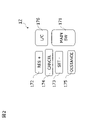
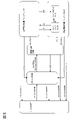
- FIG. 2 is a front view showing a part of the input device 17 of the present embodiment, and shows an example of a group of button switches arranged on the spokes of a handle or the like.
- the input device 17 is a button switch used when setting ON / OFF of the autonomous traveling control function (autonomous speed control function and autonomous steering control function) included in the control device 19.
- the input device 17 includes a main switch 171, a resume / accelerate switch 172, a set coast switch 173, a cancel switch 174, an inter-vehicle distance adjustment switch 175, and a lane change support switch 176.
- the main switch 171 is a switch that turns on / off the power of the system that realizes the autonomous speed control function and the autonomous steering control function of the control device 19.
- the resume / accelerate switch 172 stops the autonomous speed control function (OFF), then restarts the autonomous speed control function at the set speed before the OFF, increases the set speed, and controls after stopping following the preceding vehicle. It is a switch for restarting by the device 19.
- the set coast switch 173 is a switch that starts the autonomous speed control function at the traveling speed or lowers the set speed.
- the cancel switch 174 is a switch that turns off the autonomous speed control function.
- the inter-vehicle distance adjustment switch 175 is a switch for setting the inter-vehicle distance from the preceding vehicle, and is a switch for selecting one from a plurality of stages of settings such as short-distance, medium-distance, and long-distance.
- the lane change support switch 176 is a switch for instructing (accepting) the start of the lane change when the control device 19 confirms with the driver that the lane change has started. By operating the lane change support switch 176 for a longer time than a predetermined time after consenting to start the lane change, the approval of the lane change proposal by the control device 19 can be revoked.
- a direction indicator lever of a turn signal or a switch of another in-vehicle device 14 can be used as an input device 17.
- the control device 19 proposes whether or not to automatically change lanes
- the direction indicator lever is operated in the direction instead of the proposed lane change. Change lanes.
- the input device 17 outputs the input setting information to the control device 19.
- the drive control device 18 controls the running of the own vehicle. For example, when the own vehicle travels at a constant speed by the autonomous speed control function, the drive control device 18 accelerates and decelerates so that the own vehicle reaches the set speed, and maintains the traveling speed. Controls the operation of the drive mechanism and the braking operation. Further, the drive control device 18 similarly controls the operation of the drive mechanism and the brake even when the own vehicle follows the preceding vehicle by the autonomous speed control function.
- the drive control device 18 executes steering control of the own vehicle by controlling the operation of the steering actuator in addition to the operation control of the drive mechanism and the brake described above by the autonomous steering control function. For example, when the drive control device 18 executes lane keeping control by the autonomous steering control function, the drive control device 18 detects a lane marker in the own lane in which the own vehicle travels, and causes the own vehicle to travel in a predetermined position in the own lane. It controls the traveling position in the width direction of the own vehicle. Further, the drive control device 18 controls the traveling position in the width direction of the own vehicle so that the own vehicle changes lanes when the lane change support function is executed by the lane change support function described later.
- the drive control device 18 executes right / left turn support by the autonomous steering control function, the drive control device 18 performs traveling control for turning right or left at an intersection or the like.
- the drive control device 18 controls the traveling of the own vehicle according to the instruction of the control device 19 described later. Further, as a traveling control method by the drive control device 18, other known methods can also be used.
- the control device 19 includes a ROM (Read Only Memory) that stores a program for controlling the running of the own vehicle, a CPU (Central Processing Unit) that executes the program stored in the ROM, and an accessible storage device. It is equipped with a functioning RAM (RandomAccessMemory) and the like.
- RAM RandomAccessMemory
- MPU Micro Processing Unit
- DSP Digital Signal Processor
- ASIC Application Specific Integrated Circuit
- FPGA Field Programmable Gate Array
- the control device 19 has a traveling information acquisition function for acquiring information on the traveling state of the own vehicle by executing a program stored in the ROM by the CPU, a traveling scene determination function for determining the traveling scene of the own vehicle, and a self. It realizes an autonomous driving control function that autonomously controls the traveling speed and / or steering of the vehicle.
- the driving information acquisition function of the control device 19 is a function for the control device 19 to acquire driving information regarding the traveling state of the own vehicle.
- the control device 19 acquires image information outside the own vehicle captured by the front camera, the rear camera, and the side camera of the sensor 11 as driving information by the traveling information acquisition function. Further, the control device 19 acquires the detection results of the front radar, the rear radar, and the side radar as the travel information by the travel information acquisition function. Further, the control device 19 also acquires the vehicle speed information of the own vehicle detected by the vehicle speed sensor of the sensor 11 and the image information of the driver's face captured by the in-vehicle camera as the traveling information by the traveling information acquisition function.
- control device 19 acquires the current position information of the own vehicle from the own vehicle position detection device 12 as the running information by the traveling information acquisition function. Further, the control device 19 acquires the set destination and the route to the destination from the navigation device 15 as travel information by the travel information acquisition function. Further, the control device 19 uses a travel information acquisition function to provide travel information such as a curved road and the size of the curve (for example, curvature or radius of curvature), a confluence point, a branch point, a toll booth, and a position where the number of lanes is reduced. Is obtained from the map database 13. In addition, the control device 19 acquires the operation information of the vehicle-mounted device 14 by the driver from the vehicle-mounted device 14 as driving information by the traveling information acquisition function.
- travel information acquisition function to provide travel information such as a curved road and the size of the curve (for example, curvature or radius of curvature), a confluence point, a branch point, a toll booth, and a position where the number of lanes is reduced.
- the driving scene determination function of the control device 19 is a function of determining the driving scene in which the own vehicle is traveling by referring to the table stored in the ROM of the control device 19.
- a driving scene suitable for changing lanes or overtaking and a determination condition thereof are stored for each driving scene.
- the control device 19 refers to the table stored in the ROM by the traveling scene determination function, and determines whether or not the traveling scene of the own vehicle is a traveling scene suitable for, for example, changing lanes or overtaking.
- the control device 19 is detected by the traveling scene determination function, for example, the detection result by the front camera and the front radar included in the sensor 11, the vehicle speed of the own vehicle detected by the vehicle speed sensor, and the own vehicle position detection device 12. It is determined whether or not the own vehicle satisfies the above conditions based on the position information of the vehicle and the like. When the above conditions are satisfied, the control device 19 determines that the own vehicle is a "catch-up scene with the preceding vehicle".
- the autonomous travel control function of the control device 19 is a function for the control device 19 to autonomously control the travel of the own vehicle without depending on the operation of the driver.
- the autonomous travel control function of the control device 19 includes an autonomous speed control function for autonomously controlling the travel speed of the own vehicle and an autonomous steering control function for autonomously controlling the steering of the own vehicle.
- an autonomous speed control function for autonomously controlling the travel speed of the own vehicle
- an autonomous steering control function for autonomously controlling the steering of the own vehicle.
- ⁇ Autonomous speed control function> When the autonomous speed control function detects the preceding vehicle, the vehicle speed set by the driver is set as the upper limit, and the vehicle-to-vehicle distance is controlled so as to maintain the inter-vehicle distance according to the vehicle speed while following the preceding vehicle. While controlling the running motion of the own vehicle, it is a function of controlling the running motion of the own vehicle so that the vehicle runs at a constant speed at a vehicle speed set by the driver when the preceding vehicle is not detected. The former is also called inter-vehicle distance control, and the latter is also called constant speed control.
- the autonomous speed control function detects the speed limit of the traveling road from the road sign by the sensor 11, or acquires the speed limit from the map information of the map database 13, and automatically sets the speed limit to the set vehicle speed. May include a function to do.
- the driver To activate the autonomous speed control function, the driver first operates the resume / accelerate switch 172 or the set coast switch 173 of the input device 17 shown in FIG. 2 to input a desired traveling speed. For example, if the own vehicle is traveling at 70 km / h and the set coast switch 173 is pressed, the current traveling speed is set as it is, but if the speed desired by the driver is 80 km / h, resume acceleration is achieved.
- the switch 172 may be pressed multiple times to increase the set speed. On the contrary, assuming that the speed desired by the driver is 60 km / h, the set coast switch 173 may be pressed a plurality of times to reduce the set speed.
- inter-vehicle distance desired by the driver may be selected by operating the inter-vehicle distance adjustment switch 175 of the input device 17 shown in FIG. 2, for example, from a plurality of stages of settings such as short distance, medium distance, and long distance.
- the constant speed control is executed when it is detected by the front radar of the sensor 11 or the like that there is no preceding vehicle in front of the own lane.
- the control device 19 controls the operation of the drive mechanism such as the engine and the brake by the drive control device 18 while feeding back the vehicle speed data by the vehicle speed sensor so as to maintain the set running speed.
- Inter-vehicle distance control is executed when it is detected by the front radar of the sensor 11 or the like that a preceding vehicle exists in front of the own lane.
- the control device 19 feeds back the inter-vehicle distance data detected by the forward radar so as to maintain the set inter-vehicle distance with the set traveling speed as the upper limit, and the drive control device 18 causes the engine and the engine and the control device 19 to maintain the set inter-vehicle distance. Controls the operation of drive mechanisms such as brakes. If the preceding vehicle stops while traveling under the inter-vehicle distance control, the own vehicle also stops following the preceding vehicle.
- the own vehicle also starts and starts following running again by inter-vehicle distance control. If the own vehicle is stopped for more than 30 seconds, it will not start automatically even if the preceding vehicle starts, and if the preceding vehicle starts, press the resume / accelerate switch 172 or depress the accelerator pedal. , The follow-up running by the inter-vehicle distance control is started again.
- the autonomous steering control function is a function for the control device 19 to execute steering control of the own vehicle by controlling the operation of the steering actuator when a predetermined condition is satisfied during the execution of the above-mentioned autonomous speed control function.
- This autonomous steering control function includes, for example, a lane keeping function, a lane change support function, and the like.
- the lane keeping function is a function for assisting the driver in steering operation by controlling the steering actuator by the control device 19 so as to travel near the center of the lane, for example.
- the lane keeping function is also called a lane width direction maintenance function.
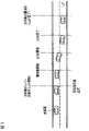
- FIG. 3 is a plan view showing a traveling scene in which a vehicle traveling in the own lane on the upper side of the drawing changes lanes to an adjacent lane on the lower side of the drawing on a road traveling from left to right in the drawing.
- the control device 19 turns on the turn signal when the driver operates the direction indicator lever, and when the preset lane change start condition is satisfied, the control device 19 changes the lane by the lane change support function.
- the lane change operation (hereinafter referred to as "LCP”), which is a series of processes of the above, is started.
- the control device 19 determines whether or not the lane change start condition is satisfied based on various driving information acquired by the driving information acquisition function by the lane change support function.
- the conditions for starting the lane change are not particularly limited, but the lane keep mode is in the hands-on mode, the hands-on judgment is in progress, the vehicle is traveling at a speed of 60 km / h or more, the lane is in the lane change direction, and the lane is changed. There is a space where you can change lanes in the destination lane, the type of lane marker can be changed, and the radius of curvature of the road is 250 m or more. Within 1 second after the driver operates the turn signal lever. It can be exemplified that all the conditions such as being satisfied are satisfied.
- the control device 19 determines that the lane change start condition is satisfied by the lane change support function even without the driver's instruction, the control device 19 notifies the driver by the presentation device 16 to propose the lane change to the driver. May be good.
- the lane keep mode of the hands-on mode will be described in detail later, but the autonomous speed control function and the lane keep function of the autonomous steering control function are being executed, and the driver's holding of the steering wheel is detected.
- “hands-on determination in progress” means a state in which the driver continues to hold the steering wheel.
- the control device 19 starts LCP by the lane change support function.
- the LCP includes lateral movement of the own vehicle to the adjacent lane and lane change maneuvering (hereinafter referred to as “LCM”) that actually moves to the adjacent lane.
- the control device 19 presents information indicating that the lane is automatically changed to the driver by the presenting device 16 while the LCP is being executed by the lane change support function, and calls attention to the surroundings.
- the control device 19 turns off the turn signal and starts executing the lane keeping function in the adjacent lane.
- a plurality of support levels are set in the driving support mode indicating the support mode in the driving operation support.
- the level of support is referred to as "support level”.
- the traveling operation of the present embodiment is various traveling operations including a lane change, for example, acceleration, deceleration, and steering to the right or left.
- the control device 19 autonomously controls the traveling of the own vehicle by combining the autonomous control of the traveling speed using the autonomous speed control function and the autonomous control of the steering operation using the autonomous steering control function by the lane change support function. , Achieve support for driving operations specified at each support level. That is, the control device 19 intervenes in the traveling motion of the vehicle within the range defined by each support level, and autonomously controls the traveling motion. For the traveling operation in which the control device 19 does not intervene, a manual operation by the driver is performed.
- the level of support is defined in, for example, SAE J3016: SEP2016, Taxonomy and Definitions for Terms Related to Driving Automation Systems for On-Road Motor Vehicles published by the American Society of Automotive Engineers (SAE). It can be set based on the level.
- support level 0 is a level at which the driver performs all the driving tasks necessary for the driving operation.
- the control device 19 continuously executes either autonomous speed control or autonomous steering control (not both at the same time) in a specific limited area, and the driver continuously executes either the autonomous speed control or the autonomous steering control of the own vehicle by the running speed of the own vehicle or steering.
- the level at which either steering (not both at the same time) is performed.
- control device 19 continuously executes autonomous speed control and autonomous steering control in a specific limited area, and the driver either runs the vehicle or steers the vehicle by steering (not both at the same time). ) Is the level to be executed.
- the support level 3 is a level at which the control device 19 continuously executes all driving tasks in a limited area.
- the support level 4 is a level at which the control device 19 executes all the operation tasks, and the response to the case where the control continuation is difficult is continuously executed in the limited area.
- Assistance level 5 is a level at which the control device 19 continuously and unlimitedly performs all driving tasks and responses to cases where continuation of control is difficult.
- Support level 1 corresponds to, for example, the control device 19 controlling the traveling speed of the own vehicle by autonomous speed control.
- the support level 2 corresponds to, for example, the control device 19 executing the lane keep mode of the hands-off mode by autonomous steering control. Therefore, the situation where the support level of the driving support mode is lowered is that, for example, when the own vehicle changes lanes from the own lane to the adjacent lane, the driving environment of the own vehicle changes and the control of the hands-off mode is continued. The condition is not satisfied, the lane keep mode of the hands-off mode cannot be maintained, and the vehicle shifts to the traveling speed control by the autonomous speed control.
- the support level of the driving support mode does not decrease while the own vehicle is autonomously following the preceding vehicle, and is maintained at least while the own vehicle is following at a traveling speed equal to or lower than the first traveling speed. It shall be done.
- the first traveling speed is such that the driver is required to monitor the autonomous traveling operation when the own vehicle autonomously follows the preceding vehicle by, for example, autonomous control of the traveling speed and the steering operation. It is a running speed that becomes.
- the first traveling speed can be set to a value within an appropriate range according to the traveling environment of the own vehicle such as the shape of the road and surrounding obstacles.
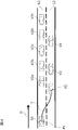
- FIG. 4 is a plan view showing a situation in which the own vehicle V1 travels on the road shown in FIG. 4, and the traveling direction of the road is the direction indicated by the arrow D in FIG.
- On the road there is a own lane L1 in which the own vehicle V1 travels and an adjacent lane L2 which is a lane adjacent to the own lane L1, and the preceding vehicles V2a to V2e travel in the own lane L1 and the preceding vehicles V3 and V4. Is traveling in the adjacent lane L2.
- FIG. 4 is a plan view showing a situation in which the own vehicle V1 travels on the road shown in FIG. 4, and the traveling direction of the road is the direction indicated by the arrow D in FIG.
- On the road there is a own lane L1 in which the own vehicle V1 travels and an adjacent lane L2 which is a lane adjacent to the own lane L1, and the preceding vehicles V2a to V2e travel in the own lane L1 and the preceding vehicles V3 and
- the adjacent lane L2 is a lane in which only a specific vehicle such as a carpool lane or a taxi lane can travel, and the own lane L1 is congested while the adjacent lane L2 is vacant. Further, it is assumed that the own vehicle V1 is executing the lane keep mode of the autonomous steering control / hands-off mode by following the preceding vehicle V2a.
- the control device 19 supports lane change in order to avoid congestion in the own lane L1 and maintain the set traveling speed.
- LCP from the own lane L1 to the adjacent lane L2 is started.
- the own vehicle V1 travels along the locus T from the traveling positions P1 to P2 by autonomous control by the control device 19.
- the own vehicle V1 cannot follow the preceding vehicle by changing lanes to the adjacent lane L2, and the support level of the driving support mode cannot be maintained. It will decrease.
- the driver's manual operation increases due to the autonomous lane change, which gives the driver a sense of discomfort.
- the driving information acquisition function uses a sensor 11 such as a front camera and a front radar.
- the preceding vehicle V3 traveling in the adjacent lane L2 is detected.
- the preceding vehicle V3 traveling in the adjacent lane L2 is not detected, in principle, the autonomous control of changing lanes of the own vehicle V1 is prohibited.
- the own vehicle is based on the traveling speed of the preceding vehicle V3 detected by the forward radar and the traveling speed of the own vehicle V1 detected by the vehicle speed sensor. It is determined whether or not V1 can follow the preceding vehicle V3.
- the own vehicle V1 it is determined whether or not the own vehicle V1 can follow the preceding vehicle V3 at a traveling speed equal to or lower than the first traveling speed. Then, when it is determined that the own vehicle V1 cannot follow the preceding vehicle V3, the autonomous control of changing the lane of the own vehicle V1 is prohibited.
- the control device 19 determines, for example, the traveling speed of the own vehicle V1 detected by the vehicle speed sensor and the traveling speed of the own vehicle V1 detected by the front radar. The difference from the traveling speed is calculated, and when the difference is equal to or less than a predetermined value, it is determined that the own vehicle V1 can follow the preceding vehicle V3.
- a predetermined value an appropriate value (for example, 0 to 10 km / h) can be set so that the own vehicle V1 can avoid a collision with the preceding vehicle V3.
- the predetermined time can be set to an appropriate time (for example, 5 to 10 seconds) at which the traveling state of the preceding vehicle V3 can be confirmed.
- the traveling speeds of the preceding vehicles V3 and V4 are detected, and the traveling speeds of the preceding vehicles V3 and V4 are used to detect a plurality of preceding vehicles V3 and V4.
- the average traveling speed of the vehicles V3 and V4 may be calculated and the average traveling speed may be set as the traveling speed of the preceding vehicle. Thereby, even when a plurality of preceding vehicles V3 and V4 are traveling in the adjacent lane L2, it is possible to appropriately determine whether or not the own vehicle V1 can follow the preceding vehicles V3 and V4.
- the number of preceding vehicles is not limited to two, and may be three or more.
- the own vehicle V1 follows the preceding vehicle V3 because the preceding vehicle traveling in the adjacent lane L2 is not detected or the traveling speed exceeds the first traveling speed. If it is determined that the vehicle cannot be changed, the autonomous control of changing the lane of the own vehicle V1 is prohibited. However, when the preceding vehicle traveling in the adjacent lane L2 is not detected, or when it is determined that the own vehicle V1 cannot follow the preceding vehicle V3, the own vehicle V1 before and after the lane change even if it does not follow the preceding vehicle.
- the second traveling speed which is the traveling speed at which the support level does not decrease
- the own vehicle V1 detects an obstacle in front by a sensor 11 such as a front camera and a front radar, and then can avoid the detected obstacle (for example, 60 km). / H) can be set. As a result, it is possible to avoid a situation in which the driver feels uncomfortable by continuing to drive in a congested lane.
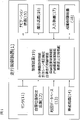
- FIG. 5 is a block diagram showing a state transition of each function established in the control device 19.
- the system shown in the figure means an autonomous traveling control system realized by the control device 19.
- the main switch 171 of FIG. 2 is turned on from the system OFF state shown in the figure, the system is put into the standby state. From this standby state, by turning on the set coast switch 173 or the resume acceleration switch 172 of FIG. 2, the autonomous speed control is activated.
- the above-mentioned constant speed control or inter-vehicle distance control is started, and the driver can drive his / her own vehicle simply by operating the steering wheel without stepping on the accelerator or the brake.
- the mode transitions to the lane keep mode of the autonomous steering control / hands-on mode.
- the condition (1) is not particularly limited, but the lane markers on both sides of the own vehicle are detected, the driver has a handle, the vehicle is traveling near the center of the lane, and the winker is activated. All conditions such as not having the wiper not operating at high speed (HI), and if there is a high-precision map, there are no tollhouses, exits, confluences, intersections, or lane reduction points within about 200 m ahead. Can be exemplified as the fact that is satisfied.
- the hands-on mode refers to a mode in which the autonomous steering control does not operate unless the driver holds the steering wheel
- the hands-off mode refers to a mode in which the autonomous steering control operates even if the driver releases his / her hand from the steering wheel.
- condition (2) in FIG. 5 If the condition (2) in FIG. 5 is satisfied while the lane keep mode of the autonomous steering control / hands-on mode is being executed, the mode transitions to the lane keep mode of the autonomous steering control / hands-off mode.
- the condition (2) is not particularly limited, but the vehicle is traveling on a motorway, is traveling on a road structurally separated from the oncoming lane, and is traveling on a road having a high-precision map. You are driving, you are driving at a vehicle speed below the speed limit, the GPS signal is valid, the driver has a handle, the driver is facing forward, and the toll booth is within about 800 m ahead.
- condition (3) in FIG. 5 is satisfied while the lane keep mode of the autonomous steering control / hands-off mode is being executed, the mode transitions to the lane keep mode of the autonomous steering control / hands-on mode.
- the condition (3) is not particularly limited, but the vehicle is traveling on a road other than a motorway, is traveling on a two-way traffic section, and is traveling on a road without a high-precision map.
- condition (4) in FIG. 5 is satisfied while the lane keep mode of the autonomous steering control / hands-off mode is being executed, the autonomous steering control is stopped and the process shifts to the autonomous speed control.
- the condition (4) is not particularly limited, but one of the following is that the lane markers on both sides of the own vehicle are not detected for a certain period of time, the driver operates the steering wheel, and the wiper operates at high speed (HI). It can be exemplified that the condition is satisfied. Further, if the condition (5) of FIG. 5 is satisfied while the lane keep mode of the autonomous steering control / hands-off mode is being executed, the autonomous steering control and the autonomous speed control are stopped and the state shifts to the standby state.
- the condition (5) is not particularly limited, but the driver operates the brake, the driver operates the cancel switch 174 in FIG. 2, the door of the own vehicle is opened, and the seat belt of the driver's seat is released. That, the seat sensor detected that the driver was no longer in the driver's seat, the select lever was other than "D” or "M”, the parking brake was activated, and the electronic stability control of the own vehicle It was turned off, the anti-skid device was activated, the snow mode was turned on, the emergency brake was activated, and after the vehicle stopped due to vehicle speed control, the stopped state continued for about 3 minutes.
- the front camera detected poor visibility such as dirt, backlight, rain / fog, etc., the front radar detected shielding, radio interference, the front radar detected axis misalignment, and the side. It can be exemplified that any of the conditions such as the radar detecting the shielding and the radio wave interference, and the side radar detecting the axis deviation are satisfied.
- condition (6) in FIG. 5 is satisfied while the autonomous steering control / hands-on mode is being executed, the autonomous steering control is stopped and the process shifts to the autonomous speed control.
- the condition (6) is not particularly limited, but the lane markers on both sides of the own vehicle are no longer detected, the driver operates the steering wheel, the driver operates the winker, and the wiper operates at high speed (HI). Either that, if there is a high-precision map, it became a tollhouse section, or that the front camera detected poor visibility that could not correctly recognize the object due to dirt, backlight, rain, fog, etc. You can exemplify what to do. Further, if the condition (7) of FIG.
- the condition (7) is not particularly limited, but the driver operates the brake, the driver operates the cancel switch 174 in FIG. 2, the door of the own vehicle is opened, and the seat belt of the driver's seat is released. That, the seating sensor detected that the driver was no longer in the driver's seat, the select lever was other than "D" or "M”, the parking brake was activated, and the electronic stability control of the own vehicle It was turned off, the anti-skid device was activated, the snow mode was turned on, the emergency brake was activated, and after the vehicle stopped due to vehicle speed control, the stopped state continued for about 3 minutes. It can be exemplified that any of the conditions such as the front radar detecting the shielding and the radio wave interference, and the front radar detecting the axis deviation are satisfied.
- the condition (8) in FIG. 5 is satisfied while the autonomous speed control is being executed, the state transitions to the standby state.
- the condition (8) is not particularly limited, but the driver operates the brake, the driver operates the cancel switch 174 in FIG. 2, the door of the own vehicle is opened, and the seat belt of the driver's seat is released. That, the seating sensor detected that the driver was no longer in the driver's seat, the select lever was other than "D” or "M”, the parking brake was activated, and the electronic stability control of the own vehicle It was turned off, the anti-skid device was activated, the snow mode was turned on, the emergency brake was activated, and after the vehicle stopped due to vehicle speed control, the stopped state continued for about 3 minutes. It can be exemplified that any of the conditions such as the front radar detecting the shielding and the radio wave interference, and the front radar detecting the axis deviation are satisfied.
- This condition (8) is not particularly limited, but is one of the conditions that the driver presses the lane change support switch 176 in FIG. 2 and the driver operates the turn signal when the system proposes a lane change. Can be exemplified as the fact that is satisfied.
- condition (10) in FIG. 5 is satisfied while the lane change mode of the autonomous steering control / hands-on mode is being executed, the mode transitions to the lane keep mode of the autonomous steering control / hands-on mode.
- This condition (10) is not particularly limited, but before the start of LCP, the speed limit was exceeded, before the start of LCP, the driver held the steering wheel and stepped on the accelerator pedal, and there was a slow car ahead. After pressing the lane change support switch 176 during the lane change proposal, the LCP could not be started within 10 seconds, and after pressing the lane change support switch 176 during the lane change proposal to drive according to the route.
- the LCP could not be started and the vehicle was too close to the branch, the actual LCM could not be started within 5 seconds after the LCP was activated, the LCP was started, and the vehicle speed was about 50 km / h before the LCM was started.
- the LCP was activated, there was no space in the adjacent lane required to change lanes before the LCM started, the driver canceled before the LCM started, and the lane marker was not before the LCM started. It was detected, it was determined that there was no adjacent lane L2 in the direction of changing lanes before the start of LCM, or there was no adjacent lane L2 within a certain distance ahead, and before the start of LCM, within a certain distance ahead.
- the driver did not have a handle within about 2 seconds after pressing the lane change support switch 176 while proposing a lane change when there was a slow car ahead without a handle, and the lane change to drive according to the route After pressing the lane change support switch 176 during the proposal, it was established under one of the conditions that the driver did not hold the handle within about 2 seconds), the driver turned off the winker, the LCP was completed, etc. It can be exemplified that any of the conditions is satisfied.
- the main switch 171 is turned off in any of the autonomous steering control / hands-off mode, autonomous steering control / hands-on mode, autonomous speed control, and standby state, the system is turned off.
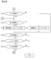
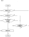
- 6A to 6B and FIG. 7 are flowcharts showing the traveling control process according to the present embodiment.
- 6A to 6B show basic travel control processing
- FIG. 7 shows a subroutine in step S10 of FIG. 6A.
- the travel control process described below is executed by the control device 19 at predetermined time intervals. Further, in the following, autonomous speed control and autonomous steering control are executed by the autonomous driving control function of the control device 19, and the vehicle is driven in the lane at a speed set by the driver in the width direction of the vehicle. It is assumed that lane keep control for controlling the traveling position is performed.
- step S1 of FIG. 6A the control device 19 determines whether or not the main switch 171 is ON.
- step S1: No the control device 19 repeats step S1 until the main switch 171 is turned ON.
- step S1: Yes the process proceeds to step S2.
- step S2 the control device 19 determines whether or not the driver has set the traveling speed. If the traveling speed is not set (step S2: No), the process returns to step S1, and the control device 19 repeats steps S1 and S2 until the traveling speed is set. On the other hand, if the traveling speed is set (step S2: Yes), the process proceeds to step S3.
- the traveling speed is set by the driver by operating the resume accelerator switch 172 or the set coast switch 173 of the input device 17 shown in FIG. 2 to input a desired traveling speed.
- step S3 the control device 19 detects whether or not there is a preceding vehicle in front of the lane in which the own vehicle travels by using the forward radar (sensor 11) that detects an obstacle in front of the own vehicle. ..
- the process proceeds to step S4, and the control device 19 executes the inter-vehicle distance control.
- step S5 the control device 19 executes constant speed control.
- the driver can drive the vehicle at a desired speed simply by operating the steering wheel without stepping on the accelerator or the brake.
- step S6 the condition (1) that the control device 19 transitions to the lane keep mode of the above-mentioned autonomous steering control / hands-on mode is satisfied. Determine if it holds. If the condition (1) is not satisfied (step S6: No), the process returns to step S3, and inter-vehicle distance control or constant speed control is continued. On the other hand, if the condition (1) is satisfied (step S6: Yes), the process proceeds to step S7.
- step S7 the control device 19 detects whether or not there is a preceding vehicle in front of the lane in which the own vehicle travels by using the forward radar (sensor 11) that detects an obstacle in front of the own vehicle.
- step S7: Yes the control device 19 proceeds to step S8 to execute the inter-vehicle distance control / lane keep mode.
- step S9 the control device 19 proceeds to step S9 to execute the constant speed control / lane keep mode. In this state, the execution process of the lane change support function in step S10 is performed. The details of step S10 will be described later.
- step S11 of FIG. 6B the control device 19 has the above-mentioned automatic steering control / hands-off. It is determined whether or not the condition (2) for transitioning to the mode is satisfied. If the condition (2) is satisfied (step S11: Yes), the process proceeds to step S12. On the other hand, if the condition (2) is not satisfied (step S11: No), the process proceeds to step S15 described later.
- step S12 in which the condition (2) for transitioning to the automatic steering control / hands-off mode is satisfied, the control device 19 uses the front radar (sensor 11) to detect an obstacle in front of the own vehicle, and the own vehicle moves. Detects whether or not there is a preceding vehicle in front of the driving lane.
- step S12: Yes the control device 19 proceeds to step S13 to execute inter-vehicle distance control, lane keep mode, and hands-off.
- step S12: No the control device 19 proceeds to step S14 to execute constant speed control, lane keep mode, and hands-off.
- step S15 the control device 19 detects whether or not there is a preceding vehicle in front of the lane in which the own vehicle travels by using the forward radar (sensor 11) that detects an obstacle in front of the own vehicle. .. If the preceding vehicle is not detected (step S15: No), the process returns to step S1, and the control device 19 continues the subsequent processing. On the other hand, when detecting the preceding vehicle (step S15: Yes), the control device 19 proceeds to step S16.
- step S16 similarly to step S6, the control device 19 determines whether or not the condition (1) for transitioning to the lane keep mode of the autonomous steering control / hands-on mode is satisfied. If the condition (1) is not satisfied (step S16: No), the process returns to step S1, and the control device 19 continues the subsequent processing. On the other hand, if the condition (1) is satisfied (step S16: Yes), the process proceeds to step S17.
- step S17 the control device 19 determines whether or not the condition (2) for transitioning to the automatic steering control / hands-off mode is satisfied, as in step S11. If the condition (2) is satisfied (step S17: Yes), the process returns to step S12 and the subsequent processing is continued. On the other hand, if the condition (2) is not satisfied (step S17: No), the process returns to step S1 and the control device 19 continues the subsequent processing.
- step S10 of FIG. 6A the process shown in FIG. 7 is executed as the execution process of the lane change support function.
- the control device 19 determines whether or not the own vehicle V1 needs to change lanes. For the determination, the route to the destination set by the navigation device 15 is used. If it is determined that the lane change is not necessary (step S21: No), the process proceeds to step S11 without executing the lane change support, and the traveling control process is continued. On the other hand, if it is determined that the lane change is necessary (step S21: Yes), the process proceeds to step S22.
- step S22 the control device 19 uses the front radar and the front camera (sensor 11) to detect an obstacle in front of the own vehicle V1 and travels in front of the own vehicle V1 in the adjacent lane L2. Detects if is present.
- step S22: Yes the process proceeds to step S23.
- step S22: No the process proceeds to step S24.
- step S23 the control device 19 determines whether or not the own vehicle V1 can follow the preceding vehicle V3 detected in step S22 at a traveling speed equal to or lower than the first traveling speed. For the determination, for example, the traveling speed of the own vehicle V1 detected by the vehicle speed sensor and the traveling speed of the preceding vehicle detected by the front radar are used, and for example, the difference in the traveling speed between the own vehicle V1 and the preceding vehicle V3 is determined. It is determined whether or not it is equal to or less than the set predetermined value.
- step S23: Yes If it is determined that the own vehicle V1 can follow the preceding vehicle V3 at a running speed equal to or lower than the first running speed (step S23: Yes), the process proceeds to step S25, and the control device 19 uses the lane change support function to support the own vehicle. Autonomous control of V1 lane change. On the other hand, if it is determined that the own vehicle V1 cannot follow the preceding vehicle V3 at a traveling speed equal to or lower than the first traveling speed (step S23: No), the process proceeds to step S24.
- step S24 the control device 19 lowers the support level of the own vehicle V1 before and after the lane change from the own lane L2 to the adjacent lane L2 even if the traveling speed of the own vehicle V1 does not follow the preceding vehicle V3. It is determined whether or not the running speed is equal to or less than the second running speed.
- the traveling speed of the own vehicle V1 is detected by using the vehicle speed sensor (sensor 11). If it is determined that the traveling speed of the own vehicle V1 is equal to or less than the second traveling speed (step S24: Yes), the process proceeds to step S25, and the control device 19 autonomously controls the lane change of the own vehicle V1 by the lane change support function. do. On the other hand, if it is determined that the traveling speed of the own vehicle V1 exceeds the second traveling speed (step S24: No), the vehicle proceeds to step S11 without executing the lane change support, and the traveling control process is continued.
- the driving support mode for supporting the driving operation of the driver by using the autonomous driving control including the autonomous control of the traveling speed and the steering operation is set.
- a support level is set to indicate how much autonomous driving control intervenes in the driving motion of the vehicle, and the support level is at least the first support level and the intervention of autonomous driving control rather than the first support level.
- the second support level is set, and the support level is set when the own vehicle V1 does not decrease from the first support level to the second support level while following the preceding vehicle V3 by autonomous driving control.
- the own vehicle V1 changes lanes from the own lane L1 in which the own vehicle V1 travels to the adjacent lane L2 of the own lane V1
- the preceding vehicle V3 traveling in the adjacent lane L2 is detected and the own vehicle V1 travels in the adjacent lane L2.
- the autonomous control of changing the lane of the own vehicle V1 is prohibited.
- the own vehicle V1 cannot follow the preceding vehicle, and the support level of the driving support mode cannot be maintained, and it is possible to avoid a decrease.
- the preceding vehicle V3 traveling in the adjacent lane L2 is detected, and when the preceding vehicle V3 traveling in the adjacent lane L2 is detected, the preceding vehicle V3 is detected. It is determined whether or not the own vehicle V1 can autonomously follow the detected preceding vehicle V3, and when it is determined that the own vehicle V1 cannot autonomously follow the detected preceding vehicle V3, the lane change of the own vehicle V1 is performed. Prohibit autonomous control of. Thereby, it is possible to determine whether or not the autonomous control of changing the lane of the own vehicle V1 is prohibited according to the traveling state of the preceding vehicle V3.
- the own vehicle V1 when it is determined whether or not the own vehicle V1 can autonomously follow the detected preceding vehicle V3, the own vehicle V1 travels.
- the speed and the traveling speed of the preceding vehicle V3 are detected, the difference between the traveling speed of the own vehicle V1 and the traveling speed of the preceding vehicle V3 is calculated, and when the difference is equal to or less than a predetermined value, the own vehicle V1 It is determined that the vehicle can follow the preceding vehicle V3. As a result, the collision between the own vehicle V1 and the preceding vehicle V3 can be further avoided.
- the situation where the difference between the travel speed of the own vehicle V1 and the travel speed of the preceding vehicle V3 is not more than a predetermined value is more than a predetermined time.
- the collision between the own vehicle V1 and the preceding vehicle V3 can be further avoided.
- the traveling speeds of the preceding vehicles V3 and V4 are detected and the preceding vehicles V3 and V4 are detected.
- the average traveling speed of the plurality of preceding vehicles V3 and V4 is calculated from the traveling speeds of the vehicles V3 and V4, and the average traveling speed is set as the traveling speed of the preceding vehicle.
- the driver monitors the autonomous travel operation when the own vehicle V1 autonomously follows the preceding vehicle by the autonomous travel control.
- the preceding vehicle V3 traveling in the adjacent lane L2 is detected in the case where the first traveling speed is set, the preceding traveling speed detected at the traveling speed equal to or lower than the first traveling speed is detected.
- the own vehicle V1 can autonomously follow the vehicle V3
- the own vehicle V1 Prohibit autonomous control of lane changes. As a result, it is possible to avoid a situation in which the driver needs to monitor due to autonomous lane change. As a result, it is possible to avoid a situation in which the driver feels uncomfortable that monitoring is required due to lane change support.
- the support level of the own vehicle V1 changes from the first support level to the second support level before and after the lane change even if the vehicle does not follow the preceding vehicle.
- the second traveling speed which is the traveling speed that does not decrease to the above
- the preceding vehicle V3 traveling in the adjacent lane L2 is not detected, or when the preceding vehicle V3 traveling in the adjacent lane L2 is autonomous.
- the adjacent lane L2 is a lane in which only a specific vehicle can travel. This makes it possible to determine whether or not autonomous control of lane change is prohibited according to the driving environment of the road.
- Driving control device 11 Sensor 12 ... Own vehicle position detection device 13 ... Map database 14 ... In-vehicle device 15 ... Navigation device 16 ... Presentation device 17 ... Input device 171 ... Main switch 172 ... Resume / accelerate switch 173 ... Set Coast switch 174 ... Cancel switch 175 ... Inter-vehicle adjustment switch 176 ... Lane change support switch 18 ... Drive control device 19 ... Control device V1 ... Own vehicle V2, V2a, V2b, V2c, V2d, V2e ... Leading vehicle (own lane) V3, V4 ... Leading vehicle (adjacent lane) L1 ... own lane L2 ... adjacent lane D ... traveling direction P1, P2 ... traveling position T ... locus
Landscapes
- Engineering & Computer Science (AREA)
- Transportation (AREA)
- Mechanical Engineering (AREA)
- Automation & Control Theory (AREA)
- Human Computer Interaction (AREA)
- Physics & Mathematics (AREA)
- Combustion & Propulsion (AREA)
- Chemical & Material Sciences (AREA)
- Mathematical Physics (AREA)
- General Physics & Mathematics (AREA)
- Control Of Driving Devices And Active Controlling Of Vehicle (AREA)
- Steering Control In Accordance With Driving Conditions (AREA)
- Traffic Control Systems (AREA)
Abstract
L'invention concerne un procédé de commande de déplacement dans lequel : au moins un premier niveau d'assistance et un second niveau d'assistance plus bas en termes de niveau d'intervention de commande de déplacement autonome que le premier niveau d'assistance sont définis en tant que niveaux d'assistance qui indiquent des niveaux pour déterminer dans quelle mesure une commande de déplacement autonome intervient dans l'opération de déplacement d'un véhicule ; et lorsqu'un véhicule hôte (V1) suit de manière autonome un véhicule précédent (V3) par le biais d'une commande de déplacement autonome et que le niveau d'assistance ne diminue pas du premier niveau d'assistance au second niveau d'assistance, si le véhicule hôte (V1) doit changer de voie à partir de la voie actuelle (L1) dans laquelle le véhicule hôte (V1) se déplace vers une voie adjacente (L2) qui est adjacente à la voie actuelle (L1), une tentative est effectuée pour détecter le véhicule précédent (V3) se déplaçant dans la voie adjacente (L2), et si aucun véhicule précédent se déplaçant dans la voie adjacente (L2) n'est détecté, une commande autonome du changement de voie par le véhicule hôte (V1) est interdite.
Priority Applications (5)
| Application Number | Priority Date | Filing Date | Title |
|---|---|---|---|
| PCT/JP2020/043201 WO2022107277A1 (fr) | 2020-11-19 | 2020-11-19 | Procédé de commande de déplacement de véhicule et dispositif de commande de déplacement |
| JP2022504046A JP7211552B2 (ja) | 2020-11-19 | 2020-11-19 | 車両の走行制御方法及び走行制御装置 |
| US17/630,844 US20230356741A1 (en) | 2020-11-19 | 2020-11-19 | Travel Control Method and Travel Control Apparatus for Vehicle |
| EP20946529.3A EP4250268A4 (fr) | 2020-11-19 | 2020-11-19 | Procédé de commande de déplacement de véhicule et dispositif de commande de déplacement |
| CN202080054880.4A CN114867650B (zh) | 2020-11-19 | 2020-11-19 | 车辆的行驶控制方法及行驶控制装置 |
Applications Claiming Priority (1)
| Application Number | Priority Date | Filing Date | Title |
|---|---|---|---|
| PCT/JP2020/043201 WO2022107277A1 (fr) | 2020-11-19 | 2020-11-19 | Procédé de commande de déplacement de véhicule et dispositif de commande de déplacement |
Publications (1)
| Publication Number | Publication Date |
|---|---|
| WO2022107277A1 true WO2022107277A1 (fr) | 2022-05-27 |
Family
ID=81708593
Family Applications (1)
| Application Number | Title | Priority Date | Filing Date |
|---|---|---|---|
| PCT/JP2020/043201 WO2022107277A1 (fr) | 2020-11-19 | 2020-11-19 | Procédé de commande de déplacement de véhicule et dispositif de commande de déplacement |
Country Status (5)
| Country | Link |
|---|---|
| US (1) | US20230356741A1 (fr) |
| EP (1) | EP4250268A4 (fr) |
| JP (1) | JP7211552B2 (fr) |
| CN (1) | CN114867650B (fr) |
| WO (1) | WO2022107277A1 (fr) |
Citations (4)
| Publication number | Priority date | Publication date | Assignee | Title |
|---|---|---|---|---|
| JP2017138900A (ja) | 2016-02-05 | 2017-08-10 | トヨタ自動車株式会社 | 車両制御システム |
| WO2018138768A1 (fr) * | 2017-01-24 | 2018-08-02 | 本田技研工業株式会社 | Système de commande de véhicule, procédé de commande de véhicule et programme de commande de véhicule |
| JP2020114699A (ja) * | 2019-01-17 | 2020-07-30 | 本田技研工業株式会社 | 車両の制御システム、車両の制御方法、およびプログラム |
| JP2020135195A (ja) * | 2019-02-15 | 2020-08-31 | 本田技研工業株式会社 | 車両制御装置、車両および車両制御方法 |
Family Cites Families (15)
| Publication number | Priority date | Publication date | Assignee | Title |
|---|---|---|---|---|
| JP4140239B2 (ja) * | 2002-01-16 | 2008-08-27 | 日産自動車株式会社 | 車両用走行制御装置 |
| JP4715754B2 (ja) * | 2007-01-10 | 2011-07-06 | 株式会社デンソー | 走行制御装置 |
| KR102329444B1 (ko) * | 2014-07-04 | 2021-11-24 | 주식회사 만도모빌리티솔루션즈 | 자동차의 제어 시스템 및 제어방법 |
| JP6394554B2 (ja) * | 2014-10-31 | 2018-09-26 | 株式会社デンソー | 運転支援装置 |
| JP2017001485A (ja) * | 2015-06-09 | 2017-01-05 | トヨタ自動車株式会社 | 車両の運転支援装置 |
| US20170123430A1 (en) * | 2015-10-30 | 2017-05-04 | Ford Global Technologies, Llc | In-path target selection during lane change |
| JP6327244B2 (ja) * | 2015-12-25 | 2018-05-23 | トヨタ自動車株式会社 | 車両制御装置 |
| JP6645649B2 (ja) * | 2016-02-17 | 2020-02-14 | 本田技研工業株式会社 | 車両制御装置、車両制御方法、および車両制御プログラム |
| KR102383427B1 (ko) * | 2016-12-16 | 2022-04-07 | 현대자동차주식회사 | 자율주행 제어 장치 및 방법 |
| JP6880747B2 (ja) * | 2017-01-10 | 2021-06-02 | いすゞ自動車株式会社 | 運転支援制御装置 |
| CN110657820A (zh) * | 2017-01-12 | 2020-01-07 | 御眼视觉技术有限公司 | 基于车辆活动的导航 |
| US20190027045A1 (en) * | 2017-07-18 | 2019-01-24 | Aptiv Technologies Limited | Automated vehicle guidance system |
| JPWO2019106788A1 (ja) * | 2017-11-30 | 2020-12-10 | 本田技研工業株式会社 | 車両制御装置、車両、及び車両制御方法 |
| JP6580115B2 (ja) * | 2017-12-18 | 2019-09-25 | 本田技研工業株式会社 | 自動運転車両の走行制御装置 |
| WO2020110186A1 (fr) * | 2018-11-27 | 2020-06-04 | 三菱電機株式会社 | Dispositif d'instruction de modification de plan de conduite et procédé d'instruction de modification de plan de conduite |
-
2020
- 2020-11-19 JP JP2022504046A patent/JP7211552B2/ja active Active
- 2020-11-19 WO PCT/JP2020/043201 patent/WO2022107277A1/fr unknown
- 2020-11-19 EP EP20946529.3A patent/EP4250268A4/fr active Pending
- 2020-11-19 US US17/630,844 patent/US20230356741A1/en active Pending
- 2020-11-19 CN CN202080054880.4A patent/CN114867650B/zh active Active
Patent Citations (4)
| Publication number | Priority date | Publication date | Assignee | Title |
|---|---|---|---|---|
| JP2017138900A (ja) | 2016-02-05 | 2017-08-10 | トヨタ自動車株式会社 | 車両制御システム |
| WO2018138768A1 (fr) * | 2017-01-24 | 2018-08-02 | 本田技研工業株式会社 | Système de commande de véhicule, procédé de commande de véhicule et programme de commande de véhicule |
| JP2020114699A (ja) * | 2019-01-17 | 2020-07-30 | 本田技研工業株式会社 | 車両の制御システム、車両の制御方法、およびプログラム |
| JP2020135195A (ja) * | 2019-02-15 | 2020-08-31 | 本田技研工業株式会社 | 車両制御装置、車両および車両制御方法 |
Non-Patent Citations (1)
| Title |
|---|
| See also references of EP4250268A4 |
Also Published As
| Publication number | Publication date |
|---|---|
| CN114867650A (zh) | 2022-08-05 |
| CN114867650B (zh) | 2023-11-14 |
| EP4250268A1 (fr) | 2023-09-27 |
| US20230356741A1 (en) | 2023-11-09 |
| JPWO2022107277A1 (fr) | 2022-05-27 |
| EP4250268A4 (fr) | 2024-01-03 |
| JP7211552B2 (ja) | 2023-01-24 |
Similar Documents
| Publication | Publication Date | Title |
|---|---|---|
| WO2020230551A1 (fr) | Procédé et dispositif de commande de déplacement de véhicule | |
| JP7143946B2 (ja) | 車両の走行制御方法及び走行制御装置 | |
| JP7140277B2 (ja) | 車両の走行制御方法及び走行制御装置 | |
| JP7164030B2 (ja) | 車両の走行制御方法及び走行制御装置 | |
| JP7434866B2 (ja) | 車両の走行制御方法および走行制御装置 | |
| WO2020230304A1 (fr) | Procédé de commande de déplacement de véhicule et dispositif de commande de déplacement | |
| JP2020185929A (ja) | 車両の走行制御方法及び走行制御装置 | |
| EP4074567A1 (fr) | Procédé de commande de conduite et dispositif de commande de conduite | |
| JP7156516B2 (ja) | 車両の走行制御方法及び走行制御装置 | |
| WO2021106159A1 (fr) | Procédé de commande de conduite et dispositif de commande de conduite | |
| WO2022107277A1 (fr) | Procédé de commande de déplacement de véhicule et dispositif de commande de déplacement | |
| RU2792474C1 (ru) | Способ управления вождением и устройство управления вождением | |
| WO2021106146A1 (fr) | Procédé de commande de déplacement et dispositif de commande de déplacement pour véhicule | |
| RU2817447C1 (ru) | Способ управления движением и устройство управления движением для транспортного средства | |
| JP2022072209A (ja) | 車両の走行制御方法及び走行制御装置 | |
| JP2022072222A (ja) | 車両の走行制御方法及び走行制御装置 | |
| JP2023059551A (ja) | 運転支援方法及び運転支援装置 | |
| JP2022079948A (ja) | 車両の走行制御方法及び走行制御装置 |
Legal Events
| Date | Code | Title | Description |
|---|---|---|---|
| ENP | Entry into the national phase |
Ref document number: 2022504046 Country of ref document: JP Kind code of ref document: A |
|
| 121 | Ep: the epo has been informed by wipo that ep was designated in this application |
Ref document number: 20946529 Country of ref document: EP Kind code of ref document: A1 |
|
| NENP | Non-entry into the national phase |
Ref country code: DE |
|
| ENP | Entry into the national phase |
Ref document number: 2020946529 Country of ref document: EP Effective date: 20230619 |