WO2020230304A1 - Procédé de commande de déplacement de véhicule et dispositif de commande de déplacement - Google Patents
Procédé de commande de déplacement de véhicule et dispositif de commande de déplacement Download PDFInfo
- Publication number
- WO2020230304A1 WO2020230304A1 PCT/JP2019/019390 JP2019019390W WO2020230304A1 WO 2020230304 A1 WO2020230304 A1 WO 2020230304A1 JP 2019019390 W JP2019019390 W JP 2019019390W WO 2020230304 A1 WO2020230304 A1 WO 2020230304A1
- Authority
- WO
- WIPO (PCT)
- Prior art keywords
- lane change
- lane
- vehicle
- function
- driver
- Prior art date
Links
- 238000000034 method Methods 0.000 title claims description 42
- 230000008859 change Effects 0.000 claims abstract description 236
- 230000004044 response Effects 0.000 claims abstract description 4
- 230000006870 function Effects 0.000 description 155
- 230000008569 process Effects 0.000 description 31
- 238000001514 detection method Methods 0.000 description 10
- 230000007246 mechanism Effects 0.000 description 9
- 239000003550 marker Substances 0.000 description 7
- 230000007704 transition Effects 0.000 description 7
- 230000001133 acceleration Effects 0.000 description 6
- 238000003825 pressing Methods 0.000 description 5
- 238000010586 diagram Methods 0.000 description 4
- 238000002485 combustion reaction Methods 0.000 description 2
- 230000000994 depressogenic effect Effects 0.000 description 2
- 125000002066 L-histidyl group Chemical group [H]N1C([H])=NC(C([H])([H])[C@](C(=O)[*])([H])N([H])[H])=C1[H] 0.000 description 1
- 238000005516 engineering process Methods 0.000 description 1
- 230000009467 reduction Effects 0.000 description 1
Images


Classifications
-
- B—PERFORMING OPERATIONS; TRANSPORTING
- B60—VEHICLES IN GENERAL
- B60W—CONJOINT CONTROL OF VEHICLE SUB-UNITS OF DIFFERENT TYPE OR DIFFERENT FUNCTION; CONTROL SYSTEMS SPECIALLY ADAPTED FOR HYBRID VEHICLES; ROAD VEHICLE DRIVE CONTROL SYSTEMS FOR PURPOSES NOT RELATED TO THE CONTROL OF A PARTICULAR SUB-UNIT
- B60W30/00—Purposes of road vehicle drive control systems not related to the control of a particular sub-unit, e.g. of systems using conjoint control of vehicle sub-units
- B60W30/18—Propelling the vehicle
- B60W30/18009—Propelling the vehicle related to particular drive situations
- B60W30/18163—Lane change; Overtaking manoeuvres
-
- B—PERFORMING OPERATIONS; TRANSPORTING
- B60—VEHICLES IN GENERAL
- B60W—CONJOINT CONTROL OF VEHICLE SUB-UNITS OF DIFFERENT TYPE OR DIFFERENT FUNCTION; CONTROL SYSTEMS SPECIALLY ADAPTED FOR HYBRID VEHICLES; ROAD VEHICLE DRIVE CONTROL SYSTEMS FOR PURPOSES NOT RELATED TO THE CONTROL OF A PARTICULAR SUB-UNIT
- B60W30/00—Purposes of road vehicle drive control systems not related to the control of a particular sub-unit, e.g. of systems using conjoint control of vehicle sub-units
- B60W30/14—Adaptive cruise control
- B60W30/143—Speed control
-
- B—PERFORMING OPERATIONS; TRANSPORTING
- B60—VEHICLES IN GENERAL
- B60W—CONJOINT CONTROL OF VEHICLE SUB-UNITS OF DIFFERENT TYPE OR DIFFERENT FUNCTION; CONTROL SYSTEMS SPECIALLY ADAPTED FOR HYBRID VEHICLES; ROAD VEHICLE DRIVE CONTROL SYSTEMS FOR PURPOSES NOT RELATED TO THE CONTROL OF A PARTICULAR SUB-UNIT
- B60W50/00—Details of control systems for road vehicle drive control not related to the control of a particular sub-unit, e.g. process diagnostic or vehicle driver interfaces
- B60W50/08—Interaction between the driver and the control system
- B60W50/10—Interpretation of driver requests or demands
-
- B—PERFORMING OPERATIONS; TRANSPORTING
- B60—VEHICLES IN GENERAL
- B60W—CONJOINT CONTROL OF VEHICLE SUB-UNITS OF DIFFERENT TYPE OR DIFFERENT FUNCTION; CONTROL SYSTEMS SPECIALLY ADAPTED FOR HYBRID VEHICLES; ROAD VEHICLE DRIVE CONTROL SYSTEMS FOR PURPOSES NOT RELATED TO THE CONTROL OF A PARTICULAR SUB-UNIT
- B60W50/00—Details of control systems for road vehicle drive control not related to the control of a particular sub-unit, e.g. process diagnostic or vehicle driver interfaces
- B60W50/08—Interaction between the driver and the control system
- B60W50/14—Means for informing the driver, warning the driver or prompting a driver intervention
-
- B—PERFORMING OPERATIONS; TRANSPORTING
- B60—VEHICLES IN GENERAL
- B60W—CONJOINT CONTROL OF VEHICLE SUB-UNITS OF DIFFERENT TYPE OR DIFFERENT FUNCTION; CONTROL SYSTEMS SPECIALLY ADAPTED FOR HYBRID VEHICLES; ROAD VEHICLE DRIVE CONTROL SYSTEMS FOR PURPOSES NOT RELATED TO THE CONTROL OF A PARTICULAR SUB-UNIT
- B60W60/00—Drive control systems specially adapted for autonomous road vehicles
- B60W60/001—Planning or execution of driving tasks
-
- B—PERFORMING OPERATIONS; TRANSPORTING
- B60—VEHICLES IN GENERAL
- B60W—CONJOINT CONTROL OF VEHICLE SUB-UNITS OF DIFFERENT TYPE OR DIFFERENT FUNCTION; CONTROL SYSTEMS SPECIALLY ADAPTED FOR HYBRID VEHICLES; ROAD VEHICLE DRIVE CONTROL SYSTEMS FOR PURPOSES NOT RELATED TO THE CONTROL OF A PARTICULAR SUB-UNIT
- B60W2540/00—Input parameters relating to occupants
- B60W2540/20—Direction indicator values
-
- B—PERFORMING OPERATIONS; TRANSPORTING
- B60—VEHICLES IN GENERAL
- B60W—CONJOINT CONTROL OF VEHICLE SUB-UNITS OF DIFFERENT TYPE OR DIFFERENT FUNCTION; CONTROL SYSTEMS SPECIALLY ADAPTED FOR HYBRID VEHICLES; ROAD VEHICLE DRIVE CONTROL SYSTEMS FOR PURPOSES NOT RELATED TO THE CONTROL OF A PARTICULAR SUB-UNIT
- B60W2540/00—Input parameters relating to occupants
- B60W2540/215—Selection or confirmation of options
-
- B—PERFORMING OPERATIONS; TRANSPORTING
- B60—VEHICLES IN GENERAL
- B60W—CONJOINT CONTROL OF VEHICLE SUB-UNITS OF DIFFERENT TYPE OR DIFFERENT FUNCTION; CONTROL SYSTEMS SPECIALLY ADAPTED FOR HYBRID VEHICLES; ROAD VEHICLE DRIVE CONTROL SYSTEMS FOR PURPOSES NOT RELATED TO THE CONTROL OF A PARTICULAR SUB-UNIT
- B60W2554/00—Input parameters relating to objects
- B60W2554/40—Dynamic objects, e.g. animals, windblown objects
- B60W2554/404—Characteristics
- B60W2554/4042—Longitudinal speed
-
- B—PERFORMING OPERATIONS; TRANSPORTING
- B60—VEHICLES IN GENERAL
- B60W—CONJOINT CONTROL OF VEHICLE SUB-UNITS OF DIFFERENT TYPE OR DIFFERENT FUNCTION; CONTROL SYSTEMS SPECIALLY ADAPTED FOR HYBRID VEHICLES; ROAD VEHICLE DRIVE CONTROL SYSTEMS FOR PURPOSES NOT RELATED TO THE CONTROL OF A PARTICULAR SUB-UNIT
- B60W2554/00—Input parameters relating to objects
- B60W2554/80—Spatial relation or speed relative to objects
- B60W2554/804—Relative longitudinal speed
-
- G—PHYSICS
- G08—SIGNALLING
- G08G—TRAFFIC CONTROL SYSTEMS
- G08G1/00—Traffic control systems for road vehicles
- G08G1/16—Anti-collision systems
- G08G1/167—Driving aids for lane monitoring, lane changing, e.g. blind spot detection
Definitions
- the present invention relates to a vehicle travel control method and a travel control device including autonomous driving control.
- Patent Document 1 As an automatic driving system mounted on a vehicle, when a driver is proposed to change lanes, a blinker operation in the direction opposite to the proposed direction is known to indicate disagreement with the lane change ( Patent Document 1).
- An object to be solved by the present invention is to provide a vehicle travel control method and a travel control device capable of reliably reflecting a driver's request for a lane change.
- the present invention presents lane change information to the driver as to whether or not to approve the execution of the lane change function, and changes the lane when the driver approves the execution of the lane change function. It has a driver trigger mode that changes lanes when a lane change instruction operation is performed. When the driver performs a lane change instruction operation after the lane change information is presented, the above problem is solved by executing the lane change function in the driver trigger mode.
- the lane change function in the driver trigger mode is executed, so that the driver's intention to change lanes can be respected. it can.
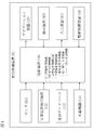
- FIG. 1 is a block diagram showing a configuration of a travel control device 1 of a vehicle (hereinafter, also referred to as own vehicle) according to the present embodiment.
- the vehicle travel control device 1 of the present embodiment is also an embodiment that implements the vehicle travel control method according to the present invention.
- the vehicle travel control device 1 according to the present embodiment includes a sensor 11, a vehicle position detection device 12, a map database 13, an in-vehicle device 14, a navigation device 15, and a presentation device 16.
- the input device 17, the drive control device 18, and the control device 19 are provided. These devices are connected by, for example, CAN (Controller Area Network) or other in-vehicle LAN in order to transmit and receive information to each other.
- CAN Controller Area Network
- the sensor 11 detects the running state of the own vehicle.
- the sensor 11 includes cameras such as a front camera that images the front of the own vehicle, a rear camera that images the rear of the own vehicle, and side cameras that image the left and right sides of the own vehicle.
- the sensor 11 includes a front radar that detects an obstacle in front of the own vehicle, a rear radar that detects an obstacle behind the own vehicle, and a side radar that detects obstacles existing on the left and right sides of the own vehicle. Etc. including radar.
- the sensor 11 includes a vehicle speed sensor that detects the vehicle speed of the own vehicle, a touch sensor (capacitance sensor) that detects the holding of the steering wheel by the driver, a driver monitor that images the driver, and the like.
- the sensor 11 may be configured to use one of the plurality of sensors described above, or may be configured to use two or more types of sensors in combination.
- the sensor 11 outputs the detection result to the control device 19 at predetermined time intervals.
- the own vehicle position detection device 12 includes a GPS unit, a gyro sensor, a vehicle speed sensor, and the like.
- the own vehicle position detection device 12 detects radio waves transmitted from a plurality of satellite communications by the GPS unit, and periodically acquires the position information of the target vehicle (own vehicle). Further, the own vehicle position detection device 12 detects the current position of the target vehicle based on the acquired position information of the target vehicle, the angle change information acquired from the gyro sensor, and the vehicle speed acquired from the vehicle speed sensor.
- the own vehicle position detection device 12 outputs the detected position information of the target vehicle to the control device 19 at predetermined time intervals.
- the map database 13 is a memory that stores three-dimensional high-precision map information including location information of various facilities and specific points and is accessible from the control device 19.
- the three-dimensional high-precision map information is three-dimensional map information based on the road shape detected when traveling on an actual road using a data acquisition vehicle.
- Three-dimensional high-precision map information, along with map information, provides detailed and highly accurate information such as curved roads and the size of the curves (for example, curvature or radius of curvature), road confluences, branch points, toll stations, and reduced lane numbers.
- the position information of is the map information associated with the three-dimensional information.
- the in-vehicle device 14 is various devices mounted on the vehicle and operates by the operation of the driver. Such in-vehicle devices include steering wheels, accelerator pedals, brake pedals, turn signals, wipers, lights, horns, and other specific switches. When the in-vehicle device 14 is operated by the driver, the in-vehicle device 14 outputs the operation information to the control device 19.
- the navigation device 15 acquires the current position information of the own vehicle from the own vehicle position detection device 12, superimposes the position of the own vehicle on the map information for navigation, and displays it on a display or the like. Further, the navigation device 15 has a navigation function of setting a route to the destination and guiding the set route to the driver when the destination is set. This navigation function displays the route on the map of the display and informs the driver of the route by voice or the like.
- the route set by the navigation device 15 is also used in the route travel support function included in the control device 19.
- the route driving support function is a function of autonomously driving the own vehicle to the destination based on the set route.
- the presentation device 16 includes various displays such as a display included in the navigation device 15, a display incorporated in a room mirror, a display incorporated in a meter unit, and a head-up display projected on a windshield. Further, the presentation device 16 includes a device other than the display, such as a speaker of an audio device and a seat device in which a vibrating body is embedded. The presentation device 16 notifies the driver of various presentation information according to the control of the control device 19.
- the input device 17 is, for example, a device such as a button switch capable of inputting manually by the driver, a touch panel arranged on the display screen, or a microphone capable of inputting by the driver's voice.
- the driver can operate the input device 17 to input the setting information for the presentation information presented by the presentation device 16.
- FIG. 2 is a front view showing a part of the input device 17 of the present embodiment, and shows an example including a group of button switches arranged on spokes of a handle or the like.
- the illustrated input device 17 is a button switch used when setting ON / OFF or the like of the autonomous driving control function (autonomous speed control function and autonomous steering control function) included in the control device 19.
- the input device 17 includes a main switch 171, a resume acceleration switch 172, a set coast switch 173, a cancel switch 174, an inter-vehicle distance adjustment switch 175, and a lane change support switch 176.
- the main switch 171 is a switch that turns on / off the power supply of the system that realizes the autonomous speed control function and the autonomous steering control function of the control device 19.
- the resume / accelerate switch 172 turns off the operation of the autonomous speed control function, then restarts the autonomous speed control function at the set speed before turning off, increases the set speed, stops following the preceding vehicle, and then restarts. It is a switch that lets you.
- the set coast switch 173 is a switch that starts the autonomous speed control function or lowers the set speed at the running speed.
- the cancel switch 174 is a switch that turns off the autonomous speed control function.
- the inter-vehicle distance adjustment switch 175 is a switch for setting the inter-vehicle distance from the preceding vehicle, and is a switch for selecting one from a plurality of stages of settings such as short distance, medium distance, and long distance.
- the lane change support switch 176 is a switch for instructing (accepting) the start of the lane change when the control device 19 confirms with the driver that the lane change has started. By operating the lane change support switch 176 for a longer time than a predetermined time after approving the start of the lane change, the approval of the lane change proposal by the control device 19 can be revoked.
- a direction indicator lever of a direction indicator and a switch of another in-vehicle device 14 can be used as an input device 17.
- the control device 19 proposes whether or not to automatically change lanes
- the direction indicator lever is operated in the direction instead of the proposed lane change. Change lanes.
- the input device 17 outputs the input setting information to the control device 19.
- the drive control device 18 controls the running of the own vehicle.
- the drive control device 18 is a drive mechanism for achieving acceleration / deceleration and traveling speed so that when the own vehicle travels at a constant speed at a set speed by the autonomous speed control function, the own vehicle has a set speed. Controls motion and braking motion. Further, the drive control device 18 also controls the operation of the drive mechanism and the brake in the same manner when the own vehicle follows the preceding vehicle by the autonomous speed control function.
- the operation control of the drive mechanism includes the operation of the internal combustion engine in the case of an engine vehicle and the operation of a traveling motor in the case of an electric vehicle system. Further, in the case of a hybrid vehicle, the torque distribution between the internal combustion engine and the traveling motor is included.
- the drive control device 18 executes steering control of the own vehicle by controlling the operation of the steering actuator in addition to the operation control of the drive mechanism and the brake described above by the autonomous steering control function. For example, when the drive control device 18 executes the lane keep control by the autonomous steering control function, the drive control device 18 detects the lane marker of the own lane in which the own vehicle travels, and causes the own vehicle to travel in a predetermined position in the own lane. Controls the traveling position of the own vehicle in the width direction. Further, when the drive control device 18 executes the lane change support function, the overtaking support function, or the route driving support function described later by the autonomous steering control function, the width direction of the own vehicle is such that the own vehicle changes lanes. Control the traveling position in.
- the drive control device 18 executes the right / left turn support function by the autonomous steering control function, the drive control device 18 performs traveling control for turning right or left at an intersection or the like.
- the drive control device 18 controls the traveling of the own vehicle according to the instruction of the control device 19 described later. Further, as a traveling control method by the drive control device 18, other known methods can also be used.
- the control device 19 includes a ROM (Read Only Memory) that stores a program for controlling the running of the own vehicle, a CPU (Central Processing Unit) that executes the program stored in the ROM, and an accessible storage device. It is equipped with a functioning RAM (Random Access Memory) and the like.
- ROM Read Only Memory
- CPU Central Processing Unit
- RAM Random Access Memory
- the operating circuit instead of or together with the CPU (Central Processing Unit), MPU (Micro Processing Unit), DSP (Digital Signal Processor), ASIC (Application Specific Integrated Circuit), FPGA (Field Programmable Gate Array), etc. Can be used.
- the control device 19 has a traveling information acquisition function for acquiring information on the traveling state of the own vehicle by executing a program stored in the ROM by the CPU, and autonomous driving for autonomously controlling the traveling speed and / or steering of the own vehicle. Realize control function.
- the traveling information acquisition function of the control device 19 is a function of acquiring traveling information regarding the traveling state of the own vehicle. For example, the control device 19 acquires image information of the outside of the vehicle captured by the front camera, the rear camera, and the side camera of the sensor 11 as the traveling information by the traveling information acquisition function. In addition, the control device 19 acquires the detection results of the front radar, the rear radar, and the side radar as driving information by the traveling information acquisition function. Further, the control device 19 also acquires the vehicle speed information of the own vehicle detected by the vehicle speed sensor of the sensor 11 and the image information of the driver's face captured by the in-vehicle camera as the traveling information by the traveling information acquisition function.
- control device 19 acquires the current position information of the own vehicle from the own vehicle position detection device 12 as the running information by the traveling information acquisition function.
- control device 19 acquires the set destination and the route to the destination from the navigation device 15 as travel information by the travel information acquisition function.
- the control device 19 uses a travel information acquisition function to provide travel information such as a curved road and the size of the curve (for example, curvature or radius of curvature), a confluence point, a branch point, a toll booth, and a position where the number of lanes is reduced. Is obtained from the map database 13.
- the control device 19 acquires the operation information of the in-vehicle device 14 by the driver as the traveling information from the in-vehicle device 14 by the traveling information acquisition function.
- the autonomous driving control function of the control device 19 is a function that autonomously controls the driving of the own vehicle without depending on the operation of the driver.
- the autonomous driving control function of the control device 19 includes an autonomous speed control function that autonomously controls the traveling speed of the own vehicle and an autonomous steering control function that autonomously controls the steering of the own vehicle.
- an autonomous speed control function that autonomously controls the traveling speed of the own vehicle
- an autonomous steering control function that autonomously controls the steering of the own vehicle.
- the autonomous speed control function is a function that, when detecting a preceding vehicle, sets the vehicle speed set by the driver as the upper limit and follows the preceding vehicle while performing inter-vehicle distance control so as to maintain the inter-vehicle distance according to the vehicle speed. ..
- the autonomous speed control function performs constant speed traveling at the vehicle speed set by the driver.
- the former is also called inter-vehicle distance control, and the latter is also called constant speed control.
- the autonomous speed control function detects the speed limit of the running road from the road sign by the sensor 11, or acquires the speed limit from the map information of the map database 13, and automatically sets the speed limit to the set vehicle speed. It may include a function to do.
- the driver To activate the autonomous speed control function, the driver first operates the resume acceleration switch 172 or the set coast switch 173 of the input device 17 shown in FIG. 2 to input a desired traveling speed. For example, if the own vehicle is running at 70 km / h and the set coast switch 173 is pressed, the current running speed is set as it is, but if the speed desired by the driver is 80 km / h, resume acceleration The set speed may be increased by pressing the switch 172 multiple times. On the contrary, assuming that the speed desired by the driver is 60 km / h, the set coast switch 173 may be pressed a plurality of times to lower the set speed.
- inter-vehicle distance desired by the driver may be selected by operating the inter-vehicle adjustment switch 175 of the input device 17 shown in FIG. 2, for example, from a plurality of stages of settings such as short distance, medium distance, and long distance.
- the constant speed control is executed when it is detected by the front radar of the sensor 11 or the like that there is no preceding vehicle in front of the own lane.
- the drive control device 18 controls the operation of the drive mechanism such as the engine and the brake while feeding back the vehicle speed data by the vehicle speed sensor so as to maintain the set running speed.
- Inter-vehicle distance control is executed when it is detected by the front radar of the sensor 11 or the like that a preceding vehicle exists in front of the own lane.
- the drive control device 18 feeds back the inter-vehicle distance data detected by the front radar so as to maintain the set inter-vehicle distance with the set traveling speed as the upper limit, and the drive mechanism such as the engine and the brake is used. Control the operation of. If the preceding vehicle stops while traveling under the inter-vehicle distance control, the own vehicle also stops following the preceding vehicle. Further, if the preceding vehicle starts within 30 seconds after the own vehicle has stopped, the own vehicle also starts and the following running by inter-vehicle distance control is started again.
- the autonomous steering control function is a function that executes steering control of the own vehicle by controlling the operation of the steering actuator when a predetermined condition is satisfied during the execution of the above-mentioned automatic speed control function.
- This autonomous steering control function includes, for example, a lane keeping function, a lane change support function, an overtaking support function, a route traveling support function, and the like.
- the lane-keeping function is a function that assists the driver in steering operation by controlling the steering actuator so as to travel near the center of the lane, for example.
- the lane keeping function is also called a lane width direction maintaining function.
- the lane change support function turns on the turn signal when the driver operates the direction indicator lever, and when the preset lane change start condition is satisfied, a series of lane change processes are performed.
- a certain lane change operation (hereinafter referred to as LCP) is started.
- the lane change support function determines whether or not the lane change start condition is satisfied based on various driving information acquired by the driving information acquisition function.
- the lane change start condition is not particularly limited, but it can be exemplified that all of the following conditions are satisfied.
- -Hands-on mode lane keep mode.
- Hands-on judgment is in progress. -The vehicle is traveling at a speed of 60 km / h or more.
- ⁇ There is a lane in the direction of lane change. ⁇ There is a space where you can change lanes in the destination lane. ⁇ The type of lane marker can be changed. -The radius of curvature of the road is 250 m or less. -Within 1 second after the driver operates the turn signal lever.
- the hands-on mode lane keep mode will be described in detail later, but is a state in which the autonomous speed control function and the lane keep function of the autonomous steering control function are being executed and the holding of the steering wheel by the driver is detected.
- “hands-on determination in progress” means a state in which the driver continues to hold the steering wheel.
- the lane change support function starts LCP when the lane change start condition is met.
- This LCP includes lateral movement of the own vehicle to the adjacent lane and lane change maneuvering (hereinafter, LCM) that actually moves to the adjacent lane.
- LCM lane change maneuvering
- the lane change support function presents information indicating that the lane is being changed automatically to the driver by the presenting device 16 to call attention to the surroundings.
- the lane change support function turns off the turn signal and starts executing the lane keeping function in the adjacent lane.
- the overtaking support function is a device that presents overtaking information when a preceding vehicle slower than the own vehicle exists in front of the own lane and satisfies a predetermined overtaking proposal condition set in advance.
- the overtaking information is information for proposing to the driver to overtake the preceding vehicle.
- the driver operates the lane change support switch 176 of the input device 17 to consent to the presentation of the overtaking information (corresponding to the consent input), and satisfies the preset overtaking start condition.
- the LCP described above is started.
- the overtaking support function determines whether or not the overtaking proposal condition and the overtaking start condition are satisfied based on various driving information acquired by the driving information acquisition function.
- the overtaking proposal condition is not particularly limited, but it can be exemplified that all of the following conditions are satisfied.
- -Hands-off mode lane keep mode -The vehicle is traveling at a speed of 60 km / h or more.
- ⁇ There is a lane in the direction of lane change.
- ⁇ There is a space in the destination lane where you can change lanes after 5 seconds.
- the type of lane marker can be changed.
- the radius of curvature of the road is 250 m or more.
- the speed of the own vehicle is 5 km / h or more slower than the set speed.
- -The speed of the preceding vehicle is 10 km / or more slower than the set speed.
- the distance between the own vehicle and the preceding vehicle is below a preset threshold value based on the speed difference between the own vehicle and the preceding vehicle. -The speed of the preceding vehicle in the lane to which the lane is changed satisfies the predetermined condition.
- the lane keep mode of the hands-off mode will be described in detail later, but is a mode in which the autonomous speed control function and the lane keep function of the autonomous steering control function are being executed and the driver does not need to hold the steering wheel.
- the condition that the speed of the preceding vehicle existing in the lane of the lane change destination satisfies a predetermined condition is applied differently depending on the type of the lane of the lane change destination. For example, on a multi-lane road with left-hand traffic, when changing lanes from the left lane to the right lane, the speed of the preceding vehicle in the left lane is about 5 km / km higher than the speed of the preceding vehicle in the right lane. The condition is that it is faster than h.
- the speed difference between the own vehicle and the preceding vehicle in the left lane is within about 5 km / h. Is a condition.
- the conditions regarding the relative speed difference between the own vehicle and the preceding vehicle are reversed on the right-hand traffic road.
- the overtaking support function turns on the turn signal and starts the LCP when the driver consents to the presentation of the overtaking information and satisfies a predetermined overtaking start condition set in advance.
- the overtaking start condition is not particularly limited, but it can be exemplified that all of the following conditions are satisfied.
- ⁇ Hands-on judgment is in progress. -The vehicle is traveling at a speed of 60 km / h or more. ⁇ There is a lane in the direction of lane change. ⁇ There is a space where you can change lanes in the destination lane. ⁇ The type of lane marker can be changed. -The radius of curvature of the road is 250 m or more.
- the speed of your vehicle is 5 km / h or more slower than the set speed (when changing lanes to the right lane by passing on the left).
- the speed of the preceding vehicle is 10 km / or more slower than the set speed (when changing lanes to the right lane by passing on the left).
- -It is within 10 seconds from the operation of the lane change support switch 176.
- the condition that the speed of the preceding vehicle is 10 km / or more slower than the set speed can be changed by the driver's setting, and the set speed after the change becomes the overtaking start condition.
- the speed that can be changed for example, 15 km / h and 20 k / can be selected in addition to 10 km / h.
- the condition that the speed of the preceding vehicle existing in the lane to which the lane is changed satisfies the predetermined condition is the same as the above-mentioned overtaking proposal condition.
- the overtaking support function starts LCP when the overtaking start condition is satisfied, and executes lateral movement to the adjacent lane and LCM. While the LCP is being executed, the overtaking support function presents information indicating that the lane is being changed automatically to the driver by the presenting device 16 to call attention to the surroundings. When the LCM is completed, the overtaking support function turns off the turn signal and starts executing the lane keeping function in the adjacent lane. Further, the overtaking support function proposes to the driver by the presenting device 16 that the driver returns to the original lane when the overtaking proposal condition is satisfied again after overtaking the preceding vehicle. If the driver accepts this proposal by operating the lane change support switch 176 of the input device 17 and satisfies the overtaking start condition, the overtaking support function returns the own vehicle to the original lane. Start LCP.
- the route travel support function has a branch point, a confluence point, an exit, a tollhouse, and other travel direction change points on the set route, the distance to the travel direction change point is within a predetermined distance, and the predetermined route.
- the route travel information is displayed by the presenting device 16 to propose a lane change to the travel direction change point.
- the route traveling support function starts LCP when the lane change proposal is accepted by the operation of the lane change support switch 176 and the predetermined route traveling start condition is satisfied.
- the route travel support function determines whether or not the route travel proposal condition and the route travel start condition are satisfied based on various travel information acquired by the travel information acquisition function.
- the normal navigation device 15 guides the route.
- the navigation function is executed.
- the route driving support function is from the right lane to the center lane when the route driving support function is within the first predetermined distance to the branch point (for example, about 2.5 km to 1.0 km before the branch point) and the route driving proposal conditions are satisfied. Propose a lane change to to based on route driving information.
- the first predetermined distance (also referred to as a lane change proposal section) is preset according to the number of lane changes required to move to the lane in which the traveling direction change point exists. For example, as shown in FIG. 6, when it is necessary to change lanes twice from the right lane to the left lane via the center lane, as illustrated, the distance to the branch point is about 2.5 km to 1.0 km before.
- the section becomes the first predetermined distance (lane change proposal section).
- the route driving proposal conditions are not particularly limited, but it can be exemplified that all of the following conditions are satisfied.
- -The destination is set by the navigation device 15.
- -The vehicle is traveling at a speed of 60 km / h or more.
- ⁇ There is a lane in the direction of lane change.
- ⁇ The type of lane marker can be changed.
- -The radius of curvature of the road is 250 m or more.
- the route driving information is presented in order to notify the driver that the lane change along the route is necessary.
- the route travel support function turns on the turn signal and starts LCP when the driver consents to the lane change for heading to the branch point and satisfies the route travel start condition.
- the route travel start condition is not particularly limited, but it can be exemplified that all of the following conditions are satisfied.
- ⁇ Hands-on judgment is in progress. -The vehicle is traveling at a speed of 60 km / h or more. ⁇ There is a lane in the direction of lane change. ⁇ There is a space where you can change lanes in the destination lane. ⁇ The type of lane marker can be changed. ⁇ You are driving in the lane change proposal section. -The radius of curvature of the road is 250 m or less.
- the route driving support function starts LCP when the route driving start condition is satisfied, and executes lateral movement to the central lane and LCM.
- the route driving support function turns off the turn signal and starts executing the lane keeping function in the central lane.
- the route driving support function presents information indicating that the lane is automatically changed to the driver by the presenting device 16 to call attention to the surroundings.
- the route driving support function is within a second predetermined distance to the branch point (for example, about 2.3 km to 700 m before the branch point) while the lane keep function is being executed in the central lane. If there is and the route travel start condition is satisfied, the direction indicator is turned on to start the second LCP, and the lane is changed from the center lane to the left lane. When the second LCM is completed, the route driving support function turns off the turn signal and starts executing the lane keeping function in the left lane.
- the route driving support function is within the third predetermined distance to the branch point (for example, about 800 m to 150 m before the branch point) while executing the lane keeping function in the left lane, and the route driving start condition is set. When it is satisfied, the turn signal is turned on. In addition, the route driving support function starts autonomous steering control from a point beyond the branch point to the branch road, and changes lanes from the left lane to the branch road. When the lane change to the branch road is completed, the route driving support function turns off the turn signal and starts executing the lane keeping function on the branch road.
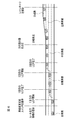
- FIG. 7 is a block diagram showing a state transition of each function established in the control device 19.
- the system shown in the figure means an autonomous driving control system realized by the control device 19.
- the main switch 171 of FIG. 2 When the main switch 171 of FIG. 2 is turned on from the system OFF state shown in the figure, the system goes into the standby state. From this standby state, the autonomous speed control is activated by turning on the set coast switch 173 or the resume acceleration switch 172 of FIG.
- the above-mentioned constant speed control or inter-vehicle distance control is started, and the driver can drive his / her own vehicle simply by operating the steering wheel without stepping on the accelerator or the brake.
- condition (1) of FIG. 7 If the condition (1) of FIG. 7 is satisfied while the autonomous speed control is being executed, the mode transitions to the lane keep mode of the autonomous steering control / hands-on mode.
- the condition (1) is not particularly limited, but it can be exemplified that all of the following conditions are satisfied. -Detects lane markers on both sides of the vehicle. ⁇ The driver has a steering wheel. ⁇ You are driving near the center of the lane. -The turn signal is not working. -The wiper is not operating at high speed (HI). ⁇ If there is a high-precision map, there are no tollhouses, exits, confluences, intersections, or points where the number of lanes is reduced within about 200 m ahead.
- the hands-on mode is a mode in which the autonomous steering control does not operate unless the driver holds the steering wheel
- the hands-off mode is a mode in which the autonomous steering control is activated even if the driver releases the steering wheel.
- the holding of the steering wheel by the driver is detected by the touch sensor of the sensor 11.
- condition (2) of FIG. 7 If the condition (2) of FIG. 7 is satisfied while the lane keep mode of the autonomous steering control / hands-on mode is being executed, the mode transitions to the lane keep mode of the autonomous steering control / hands-off mode.
- this condition (2) it can be exemplified that all of the following conditions are satisfied. ⁇ Your vehicle is traveling on a car-only road. ⁇ You are driving on a road that is structurally separated from the oncoming lane. ⁇ You are driving on a road with a high-precision map. ⁇ The vehicle is traveling at a speed below the speed limit. -GPS signals are valid. ⁇ The driver has a steering wheel. ⁇ The driver is facing forward.
- ⁇ There are no tollhouses, exits, confluences, intersections, or points where the number of lanes is reduced within about 800 m ahead. -There is no sharp curve of 100R or less within about 500m ahead. ⁇ Do not drive in a tunnel that exceeds 500 m from the tunnel entrance. ⁇ The accelerator pedal is not depressed. Whether or not the driver is facing forward is determined based on, for example, an image captured by the driver monitor camera of the sensor 11.
- the condition (3) is not particularly limited, but it can be exemplified that any of the following conditions is satisfied. ⁇ Your vehicle is traveling on a road other than a motorway. ⁇ You are driving in a two-way section. ⁇ You are driving on a road that does not have a high-precision map. ⁇ The vehicle is traveling at a speed that exceeds the speed limit. ⁇ GPS signals can no longer be received. -The driver did not turn forward within 5 seconds after the forward gaze alarm was activated.
- the driver monitor camera can no longer detect the driver.
- ⁇ There is a tollhouse, exit, merging, or reduction in the number of lanes about 800m ahead. -When the vehicle is traveling at a speed of less than about 40 km / h, there is a sharp curve of 100R or less within about 200 m ahead. -When the vehicle is traveling at a speed of about 40 km / h or more, there is a sharp curve of 170R or less within about 200 m ahead.
- the driver is holding the steering wheel and stepping on the accelerator pedal.
- ⁇ The approach alarm is activated.
- condition (4) of FIG. 7 is satisfied while the lane keep mode of the autonomous steering control / hands-off mode is being executed, the autonomous steering control is stopped and the process shifts to the autonomous speed control.
- the condition (4) is not particularly limited, but it can be exemplified that any of the following conditions is satisfied. -The lane markers on both sides of the vehicle are no longer detected for a certain period of time. -The driver is operating the steering wheel. -The wiper is operating at high speed (HI). The steering wheel operation by the driver is determined by detecting the torque applied to the steering wheel.
- condition (5) of FIG. 7 is satisfied while the lane keep mode of the autonomous steering control / hands-off mode is being executed, the autonomous steering control and the autonomous speed control are stopped and the state shifts to the standby state.
- the condition (5) is not particularly limited, but it can be exemplified that any of the following conditions is satisfied.
- ⁇ The driver operated the brake.
- the door of my vehicle has opened.
- the driver's seat belt was released.
- the seating sensor detected that the driver had left the driver's seat.
- the select lever is other than "D" or "M”.
- the parking brake has been activated.
- the electronic stability control of the vehicle has been turned off.
- the electronic stability control has been activated.
- -Snow mode has been turned on.
- the emergency brake was activated.
- the stopped state continued for about 3 minutes.
- the front camera detected poor visibility such as being unable to correctly recognize the object due to dirt, backlight, rain, fog, etc.
- the front radar detected shielding and radio interference.
- the forward radar detected an axis shift.
- Side radar detected shielding and radio interference.
- the side radar detected the axis deviation.
- condition (6) of FIG. 7 is satisfied while the autonomous steering control / hands-on mode is being executed, the autonomous steering control is stopped and the process shifts to the autonomous speed control.
- the condition (6) is not particularly limited, but it can be exemplified that any of the following conditions is satisfied. -The lane markers on both sides of the vehicle are no longer detected. ⁇ The driver operated the steering wheel. ⁇ The driver operated the turn signal lever. -The wiper operated at high speed (HI). ⁇ If there is a high-precision map, it becomes a tollhouse section. -The front camera detected poor visibility that could not correctly recognize the object due to dirt, backlight, rain, fog, etc.
- condition (7) of FIG. 7 is satisfied while the autonomous steering control / hands-on mode is being executed, the autonomous steering control and the autonomous speed control are stopped and the state shifts to the standby state.
- the condition (7) is not particularly limited, but it can be exemplified that any of the following conditions is satisfied.
- ⁇ The driver operated the brake.
- -The driver operated the cancel switch 174 in FIG.
- the door of my vehicle has opened.
- ⁇ The driver's seat belt was released.
- the seating sensor detected that the driver had left the driver's seat.
- the select lever is other than "D" or "M”.
- the parking brake has been activated.
- -The electronic stability control of the vehicle has been turned off. -The electronic stability control has been activated.
- the condition (8) of FIG. 7 is satisfied while the autonomous speed control is being executed, the state transitions to the standby state.
- the condition (8) is not particularly limited, but it can be exemplified that any of the following conditions is satisfied.
- ⁇ The river operated the brake.
- -The driver operated the cancel switch 174 in FIG.
- the door of my vehicle has opened.
- ⁇ The driver's seat belt was released.
- ⁇ The seating sensor detected that the driver had left the driver's seat.
- -The select lever is other than "D" or "M”.
- the parking brake has been activated.
- -The electronic stability control of the vehicle has been turned off.
- -The electronic stability control has been activated.
- -Snow mode has been turned on.
- the emergency brake was activated.
- ⁇ The front radar detected shielding and radio interference.
- ⁇ The forward radar detected an axis shift.
- condition (9) of FIG. 7 If the condition (9) of FIG. 7 is satisfied while the lane keep mode of the autonomous steering control / hands-off mode is being executed, the mode transitions to the lane change mode of the autonomous steering control / hands-on mode.
- the condition (8) is not particularly limited, but it can be exemplified that any of the following conditions is satisfied. -The system proposed a lane change based on the overtaking support function or the route driving support function, and the driver operated the lane change support switch 176. -The driver operated the turn signal lever to execute the lane change support mechanism.
- condition (10) of FIG. 7 is satisfied while the lane change mode of the autonomous steering control / hands-on mode is being executed, the mode transitions to the lane keep mode of the autonomous steering control / hands-on mode.
- the condition (10) is not particularly limited, but it can be exemplified that any of the following conditions is satisfied. -The speed limit was exceeded before the start of LCP. -Before the start of LCP, the driver held the steering wheel and stepped on the accelerator pedal. -LCP could not be started within 10 seconds after pressing the lane change support switch 176 while proposing a lane change when there was a slow car ahead.
- the hands-on alarm is activated when any of the following conditions is satisfied. -The driver did not hold the steering wheel within about 2 seconds after the LCP was activated. -The driver did not hold the steering wheel within about 2 seconds after pressing the lane change support switch 176 while proposing a lane change when there was a slow car ahead. -The driver did not hold the steering wheel within about 2 seconds after pressing the lane change support switch 176 while proposing a lane change to drive according to the route.
- the main switch 171 is turned off in any of the autonomous steering control / hands-off mode, autonomous steering control / hands-on mode, autonomous speed control, and standby state, the system is turned off.
- FIG. 8 is a flowchart showing the traveling control process according to the present embodiment.
- the control device 19 executes the travel control process described below at predetermined time intervals.
- lane change support control and overtaking which execute autonomous speed control and autonomous steering control by the autonomous driving control function of the control device 19, and realize the lane change support function, the overtaking support function, and the route driving support function, respectively. It will be described as being executed by the support control and the route driving support control.
- step S1 of FIG. 8 it is determined whether or not the main switch 171 of the control device 19 is ON, and if the main switch 171 is OFF, step S1 is repeated until it is turned ON. If the main switch 171 is ON, the process proceeds to step S2, and it is determined whether or not the traveling speed is set by the driver. If the traveling speed is not set, the process returns to step S1 and steps S1 and S2 are repeated until the traveling speed is set. The traveling speed is set by the driver by operating the resume acceleration switch 172 or the set coast switch 173 of the input device 17 shown in FIG. 2 to input a desired traveling speed.
- step S3 When the running speed is set, autonomous speed control is started.
- step S3 when the front radar (sensor 11) that detects an obstacle in front of the own vehicle is used to detect whether or not the preceding vehicle exists in front of the lane in which the own vehicle travels, and the preceding vehicle exists. Proceeds to step S4 to execute inter-vehicle distance control. If there is no preceding vehicle, the process proceeds to step S5 to execute constant speed control. As a result, the driver can drive the own vehicle at a desired speed simply by operating the steering wheel without stepping on the accelerator or the brake.
- step S6 Whether or not the condition (1) for transitioning to the above-mentioned autonomous steering control / hands-on mode lane keep mode is satisfied in step S6 while the inter-vehicle distance control in step S4 or the constant speed control in step S5 is being executed. To judge. If the condition (1) is satisfied, the process proceeds to step S7, and if the condition (1) is not satisfied, the process returns to step S3.
- step S7 it is detected whether or not there is a preceding vehicle in front of the lane in which the own vehicle is traveling by using the front radar (sensor 11) that detects an obstacle in front of the own vehicle. If there is a preceding vehicle, the process proceeds to step S8 to execute the inter-vehicle distance control / lane keep mode. If there is no preceding vehicle, the process proceeds to step S9 to execute the constant speed control / lane keep mode.
- step S12 determines whether there is a preceding vehicle. If there is a preceding vehicle, the process proceeds to step S12 to execute inter-vehicle distance control, lane keep mode, and hands-off. If there is no preceding vehicle, the process proceeds to step S13 to execute constant speed control, lane keep mode, and hands-off.
- step S14 it is determined whether or not the direction indicator lever has been operated by the driver.
- the condition (9) for transitioning to the lane change mode of the automatic steering / hands-on mode is satisfied, and the process proceeds to step S15.
- step S15 lane change support control is executed. When the lane change support control in step S15 is completed, the process returns to step S3. If the direction indicator lever is not operated by the driver in step S14, the process proceeds to step S16.
- step S16 it is determined whether or not there is a preceding vehicle slower than the set speed. If there is a preceding vehicle slower than the set speed, it is determined whether or not the condition (9) is satisfied, and if the condition (9) is satisfied, the mode shifts to the lane change mode of the automatic steering / hands-on mode. Then, the process proceeds to step S17.
- step S17 overtaking support control is executed. When the overtaking support control in step S17 is completed, the process returns to step S3. If there is no preceding vehicle slower than the set speed in step S16, the process proceeds to step S18.
- step S18 it is determined whether the navigation device 15 has a route to the destination. If no route has been set, the process returns to step 1. If a route to the destination is set in the navigation device 15 in step S18, the process proceeds to step S19. In step S19, it is determined whether or not a predetermined distance has been reached to a traveling direction change point such as a branch point existing on the route. When the predetermined distance has been reached to the traveling direction change point in step S19, it is determined whether or not the condition (9) is satisfied, and when the condition (9) is satisfied, the automatic steering / hands-on mode is set. The mode shifts to the lane change mode, and the process proceeds to step S20. In step S20, route traveling support control is executed. When the route travel support control in step S20 is completed, the process returns to step S3. If the predetermined distance has not been reached to the traveling direction change point in step S19, the process returns to step S1.
- the necessity of lane change support control, overtaking support control, and route driving support control is determined in order, but in reality, the necessity of each control is determined in parallel, and any of them is determined. If it becomes necessary to execute another support control during the execution of the support control of, the necessity of execution is arbitrated between the support controls, and the support control to be executed preferentially is determined.
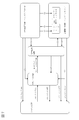
- control as shown in the flowchart shown in FIG. 9 is performed.
- the overtaking information by the overtaking support function is presented in step S30 and the direction indicator lever is operated in step S32 without inputting the consent for the overtaking information in step S31
- the lane change by the lane change support function is performed in step S33. Will be executed. As a result, the driver's intention to change lanes is prioritized.
- step S36 it is determined whether or not the lane change direction of the overtaking information and the operation direction of the direction indicator lever are the same.
- the process proceeds to step S37, and the lane change by the lane change support function is executed instead of the lane change by the overtaking support function.
- the driver's intention is prioritized. In this case, giving priority to the driver's intention to change lanes, in step S39, the lane change information for returning from the lane to which the lane is changed to the original lane is not presented.
- step S36 determines that the consent input has been canceled in step S38, and the overtaking support function is used.
- the lane change is canceled.
- the lane change by the overtaking support function is stopped in step S38.
- This predetermined time may use a predetermined threshold value, or may be changed based on, for example, the reason why the overtaking support function is executed. For example, since the speed of the preceding vehicle is slow, when overtaking the preceding vehicle, the predetermined time is set to about 10 seconds, and when the lane change required to proceed along the route by the route driving support function is 2 minutes and 30 seconds. It is about seconds.
- the vehicle travel control device 1 and the travel control method according to the present embodiment when a predetermined condition for executing the lane change is satisfied, the vehicle is changed to the lane by autonomous driving control.
- the driver is presented with lane change information as to whether or not to approve the execution of the lane change function, and in response to the presentation of the lane change information, the driver's consent input to consent to the execution of the lane change function is detected.
- it has a system trigger mode that executes the lane change function and a driver trigger mode that executes the lane change function when the driver performs a lane change instruction operation different from the consent input.
- the lane change function in the driver trigger mode is executed.
- the driver's intention to change lanes can be prioritized and the lane change function in the driver trigger mode can be executed.
- the driver when a predetermined condition for executing the lane change is satisfied, the driver is presented with lane change information as to whether or not to consent to the execution of the lane change function that causes the vehicle to change lanes by autonomous driving control.
- the system trigger mode that executes the lane change function when the driver's consent input to consent to the execution of the lane change function is detected, and the driver's consent input Is equipped with a driver trigger mode that executes a lane change function when a different predetermined lane change instruction operation is performed, and lane change information when a lane change instruction operation is performed after input of consent by the driver.
- the lane change function by the driver trigger mode is used instead of the lane change function by the system trigger mode. Run. If the lane change direction presented in the lane change information and the lane change direction instructed by the lane change instruction operation are opposite to each other, the consent input is cancelled. As a result, even if the driver approves the proposal for changing lanes in the system trigger mode, the driver's intention to change lanes can be prioritized and the lane change function in the driver trigger mode can be executed.
- the lane change information for returning from the lane change destination lane to the original lane is not presented. It is possible to give priority to the driver's intention to change lanes and continue driving in the lane to which the lane is changed.
- the operation unit that allows the driver to operate while holding the steering wheel is used for consent input and the direction indicator lever is used for lane change instruction operation, it is based on the consent to the system trigger mode and the driver's intention.
- the operation can be clearly separated from the lane change, and the occurrence of erroneous operation can be prevented.
- Driving control device 11 Sensor 12 ... Own vehicle position detection device 13 ... Map database 14 ... In-vehicle device 15 ... Navigation device 16 ... Presentation device 17 ... Input device 171 ... Main switch 172 ... Resume / accelerate switch 173 ... Set Coast switch 174 ... Cancel switch 175 ... Inter-vehicle adjustment switch 176 ... Lane change support switch 177 ... Display screen 178 ... ON button 179 ... OFF button 18 ... Drive control device 19 ... Control device
Landscapes
- Engineering & Computer Science (AREA)
- Automation & Control Theory (AREA)
- Transportation (AREA)
- Mechanical Engineering (AREA)
- Human Computer Interaction (AREA)
- Control Of Driving Devices And Active Controlling Of Vehicle (AREA)
- Traffic Control Systems (AREA)
Abstract
La présente invention présente des informations de changement de voie indiquant s'il faut autoriser l'exécution d'une fonction de changement automatique de voie, qui permet à un véhicule de réaliser un changement de voie par une commande de déplacement automatique, si une condition de début de la fonction de changement automatique de voie est satisfaite, et comprend : un mode de déclenchement par le système pour exécuter la fonction de changement automatique de voie si une entrée d'autorisation d'exécution de la fonction de changement automatique de voie est détectée en réponse à la présentation d'informations de changement de voie; et un mode de déclenchement par le conducteur pour exécuter la fonction de changement automatique de voie si une opération de commande de changement de voie qui est différente de l'entrée d'autorisation, est réalisée. Si l'opération de commande de changement de voie est réalisée après la présentation des informations de changement de voie, la fonction de changement automatique de voie selon le mode de déclenchement par le conducteur est exécutée.
Priority Applications (5)
| Application Number | Priority Date | Filing Date | Title |
|---|---|---|---|
| US17/609,833 US11505194B2 (en) | 2019-05-15 | 2019-05-15 | Vehicle travel control method and travel control device |
| CN201980096246.4A CN113811934B (zh) | 2019-05-15 | 2019-05-15 | 车辆的行驶控制方法及行驶控制装置 |
| PCT/JP2019/019390 WO2020230304A1 (fr) | 2019-05-15 | 2019-05-15 | Procédé de commande de déplacement de véhicule et dispositif de commande de déplacement |
| EP19928313.6A EP3971860A4 (fr) | 2019-05-15 | 2019-05-15 | Procédé de commande de déplacement de véhicule et dispositif de commande de déplacement |
| JP2021519214A JP7156517B2 (ja) | 2019-05-15 | 2019-05-15 | 車両の走行制御方法及び走行制御装置 |
Applications Claiming Priority (1)
| Application Number | Priority Date | Filing Date | Title |
|---|---|---|---|
| PCT/JP2019/019390 WO2020230304A1 (fr) | 2019-05-15 | 2019-05-15 | Procédé de commande de déplacement de véhicule et dispositif de commande de déplacement |
Publications (1)
| Publication Number | Publication Date |
|---|---|
| WO2020230304A1 true WO2020230304A1 (fr) | 2020-11-19 |
Family
ID=73289154
Family Applications (1)
| Application Number | Title | Priority Date | Filing Date |
|---|---|---|---|
| PCT/JP2019/019390 WO2020230304A1 (fr) | 2019-05-15 | 2019-05-15 | Procédé de commande de déplacement de véhicule et dispositif de commande de déplacement |
Country Status (5)
| Country | Link |
|---|---|
| US (1) | US11505194B2 (fr) |
| EP (1) | EP3971860A4 (fr) |
| JP (1) | JP7156517B2 (fr) |
| CN (1) | CN113811934B (fr) |
| WO (1) | WO2020230304A1 (fr) |
Cited By (3)
| Publication number | Priority date | Publication date | Assignee | Title |
|---|---|---|---|---|
| JP2021062696A (ja) * | 2019-10-11 | 2021-04-22 | 本田技研工業株式会社 | 車両制御装置、車両制御方法、およびプログラム |
| JP2021138246A (ja) * | 2020-03-04 | 2021-09-16 | 本田技研工業株式会社 | 車両制御装置及び車両制御方法 |
| CN114194193A (zh) * | 2021-01-11 | 2022-03-18 | 广东科学技术职业学院 | 一种控制车辆变道的方法 |
Families Citing this family (2)
| Publication number | Priority date | Publication date | Assignee | Title |
|---|---|---|---|---|
| JP7474136B2 (ja) * | 2020-06-30 | 2024-04-24 | 本田技研工業株式会社 | 制御装置、制御方法、およびプログラム |
| US20230237904A1 (en) * | 2022-01-24 | 2023-07-27 | Qualcomm Incorporated | Smart traffic management |
Citations (5)
| Publication number | Priority date | Publication date | Assignee | Title |
|---|---|---|---|---|
| JP2016071514A (ja) | 2014-09-29 | 2016-05-09 | 富士重工業株式会社 | 運転支援制御装置 |
| JP2016197390A (ja) * | 2015-04-03 | 2016-11-24 | 株式会社デンソー | 起動提案装置及び起動提案方法 |
| JP2018030479A (ja) * | 2016-08-25 | 2018-03-01 | スズキ株式会社 | 車両の走行制御装置 |
| JP2018092538A (ja) * | 2016-12-07 | 2018-06-14 | トヨタ自動車株式会社 | 車両走行制御装置 |
| JP2019043432A (ja) * | 2017-09-05 | 2019-03-22 | 本田技研工業株式会社 | 車両制御システム、車両制御方法、およびプログラム |
Family Cites Families (14)
| Publication number | Priority date | Publication date | Assignee | Title |
|---|---|---|---|---|
| JP4329088B2 (ja) | 1998-02-18 | 2009-09-09 | 株式会社エクォス・リサーチ | 車両制御装置 |
| US6577334B1 (en) | 1998-02-18 | 2003-06-10 | Kabushikikaisha Equos Research | Vehicle control |
| JP4565420B2 (ja) | 2000-11-22 | 2010-10-20 | マツダ株式会社 | 車線逸脱防止装置 |
| WO2015145606A1 (fr) * | 2014-03-26 | 2015-10-01 | 日産自動車株式会社 | Dispositif de présentation d'informations et procédé de présentation d'informations |
| JP6103716B2 (ja) * | 2014-06-17 | 2017-03-29 | 富士重工業株式会社 | 車両の走行制御装置 |
| JP5970513B2 (ja) * | 2014-09-29 | 2016-08-17 | 富士重工業株式会社 | 運転支援制御装置 |
| JP6332170B2 (ja) * | 2015-07-01 | 2018-05-30 | トヨタ自動車株式会社 | 自動運転制御装置 |
| EP3150465B1 (fr) * | 2015-10-01 | 2018-12-12 | Volvo Car Corporation | Procédé et système pour indiquer un changement de voie potentielle d'un véhicule |
| JP6517161B2 (ja) * | 2016-02-18 | 2019-05-22 | 本田技研工業株式会社 | 走行制御装置 |
| JP6464107B2 (ja) * | 2016-02-22 | 2019-02-06 | 本田技研工業株式会社 | 走行支援装置 |
| US10328973B2 (en) * | 2017-03-06 | 2019-06-25 | Ford Global Technologies, Llc | Assisting drivers with roadway lane changes |
| JP6693447B2 (ja) * | 2017-03-13 | 2020-05-13 | 株式会社デンソー | 走行制御装置 |
| JP6568559B2 (ja) * | 2017-09-13 | 2019-08-28 | 株式会社Subaru | 車両の走行制御装置 |
| JP7115184B2 (ja) * | 2018-09-26 | 2022-08-09 | トヨタ自動車株式会社 | 自動運転システム |
-
2019
- 2019-05-15 JP JP2021519214A patent/JP7156517B2/ja active Active
- 2019-05-15 EP EP19928313.6A patent/EP3971860A4/fr active Pending
- 2019-05-15 WO PCT/JP2019/019390 patent/WO2020230304A1/fr unknown
- 2019-05-15 US US17/609,833 patent/US11505194B2/en active Active
- 2019-05-15 CN CN201980096246.4A patent/CN113811934B/zh active Active
Patent Citations (5)
| Publication number | Priority date | Publication date | Assignee | Title |
|---|---|---|---|---|
| JP2016071514A (ja) | 2014-09-29 | 2016-05-09 | 富士重工業株式会社 | 運転支援制御装置 |
| JP2016197390A (ja) * | 2015-04-03 | 2016-11-24 | 株式会社デンソー | 起動提案装置及び起動提案方法 |
| JP2018030479A (ja) * | 2016-08-25 | 2018-03-01 | スズキ株式会社 | 車両の走行制御装置 |
| JP2018092538A (ja) * | 2016-12-07 | 2018-06-14 | トヨタ自動車株式会社 | 車両走行制御装置 |
| JP2019043432A (ja) * | 2017-09-05 | 2019-03-22 | 本田技研工業株式会社 | 車両制御システム、車両制御方法、およびプログラム |
Cited By (4)
| Publication number | Priority date | Publication date | Assignee | Title |
|---|---|---|---|---|
| JP2021062696A (ja) * | 2019-10-11 | 2021-04-22 | 本田技研工業株式会社 | 車両制御装置、車両制御方法、およびプログラム |
| JP2021138246A (ja) * | 2020-03-04 | 2021-09-16 | 本田技研工業株式会社 | 車両制御装置及び車両制御方法 |
| CN114194193A (zh) * | 2021-01-11 | 2022-03-18 | 广东科学技术职业学院 | 一种控制车辆变道的方法 |
| CN114194193B (zh) * | 2021-01-11 | 2023-06-27 | 广东科学技术职业学院 | 一种控制车辆变道的方法 |
Also Published As
| Publication number | Publication date |
|---|---|
| CN113811934A (zh) | 2021-12-17 |
| JP7156517B2 (ja) | 2022-10-19 |
| EP3971860A4 (fr) | 2022-12-14 |
| JPWO2020230304A1 (fr) | 2020-11-19 |
| CN113811934B (zh) | 2022-11-04 |
| EP3971860A1 (fr) | 2022-03-23 |
| US11505194B2 (en) | 2022-11-22 |
| US20220203993A1 (en) | 2022-06-30 |
Similar Documents
| Publication | Publication Date | Title |
|---|---|---|
| JP7140277B2 (ja) | 車両の走行制御方法及び走行制御装置 | |
| JP7143946B2 (ja) | 車両の走行制御方法及び走行制御装置 | |
| WO2020230551A1 (fr) | Procédé et dispositif de commande de déplacement de véhicule | |
| WO2020230304A1 (fr) | Procédé de commande de déplacement de véhicule et dispositif de commande de déplacement | |
| JP7164030B2 (ja) | 車両の走行制御方法及び走行制御装置 | |
| JP7434866B2 (ja) | 車両の走行制御方法および走行制御装置 | |
| JP7331450B2 (ja) | 車両の走行制御方法及び走行制御装置 | |
| JP7268433B2 (ja) | 車両用制御装置 | |
| JP7156516B2 (ja) | 車両の走行制御方法及び走行制御装置 | |
| US20230347926A1 (en) | Driving control method and driving control device | |
| WO2023089837A1 (fr) | Procédé d'aide au déplacement et dispositif d'aide au déplacement pour véhicule | |
| WO2023089835A1 (fr) | Procédé et dispositif d'aide au déplacement d'un véhicule | |
| JP7211552B2 (ja) | 車両の走行制御方法及び走行制御装置 | |
| WO2021106146A1 (fr) | Procédé de commande de déplacement et dispositif de commande de déplacement pour véhicule | |
| RU2780638C1 (ru) | Способ управления движением транспортного средства и устройство управления движением | |
| WO2022195775A1 (fr) | Procédé de commande de déplacement et dispositif de commande de déplacement pour un véhicule | |
| RU2780639C1 (ru) | Способ управления движением и устройство управления движением для транспортного средства | |
| WO2024013997A1 (fr) | Procédé d'aide à la conduite et dispositif d'aide à la conduite | |
| WO2024013996A1 (fr) | Procédé d'aide à la conduite et dispositif d'aide à la conduite pour véhicule |
Legal Events
| Date | Code | Title | Description |
|---|---|---|---|
| 121 | Ep: the epo has been informed by wipo that ep was designated in this application |
Ref document number: 19928313 Country of ref document: EP Kind code of ref document: A1 |
|
| ENP | Entry into the national phase |
Ref document number: 2021519214 Country of ref document: JP Kind code of ref document: A |
|
| NENP | Non-entry into the national phase |
Ref country code: DE |
|
| ENP | Entry into the national phase |
Ref document number: 2019928313 Country of ref document: EP Effective date: 20211215 |