WO2020230551A1 - Procédé et dispositif de commande de déplacement de véhicule - Google Patents
Procédé et dispositif de commande de déplacement de véhicule Download PDFInfo
- Publication number
- WO2020230551A1 WO2020230551A1 PCT/JP2020/017234 JP2020017234W WO2020230551A1 WO 2020230551 A1 WO2020230551 A1 WO 2020230551A1 JP 2020017234 W JP2020017234 W JP 2020017234W WO 2020230551 A1 WO2020230551 A1 WO 2020230551A1
- Authority
- WO
- WIPO (PCT)
- Prior art keywords
- vehicle
- control
- autonomous
- target point
- lane
- Prior art date
Links
- 238000000034 method Methods 0.000 title claims description 37
- 238000003860 storage Methods 0.000 claims abstract description 10
- 230000008859 change Effects 0.000 description 74
- 230000006870 function Effects 0.000 description 62
- 230000008569 process Effects 0.000 description 22
- 230000006399 behavior Effects 0.000 description 13
- 238000001514 detection method Methods 0.000 description 13
- 230000007704 transition Effects 0.000 description 8
- 230000001133 acceleration Effects 0.000 description 7
- 238000012790 confirmation Methods 0.000 description 7
- 238000010586 diagram Methods 0.000 description 7
- 230000004397 blinking Effects 0.000 description 6
- 238000012545 processing Methods 0.000 description 6
- 238000003825 pressing Methods 0.000 description 5
- 230000007246 mechanism Effects 0.000 description 4
- 230000009467 reduction Effects 0.000 description 3
- 238000002485 combustion reaction Methods 0.000 description 2
- 125000002066 L-histidyl group Chemical group [H]N1C([H])=NC(C([H])([H])[C@](C(=O)[*])([H])N([H])[H])=C1[H] 0.000 description 1
- 238000013459 approach Methods 0.000 description 1
- 230000000994 depressogenic effect Effects 0.000 description 1
- 238000009826 distribution Methods 0.000 description 1
- 239000000284 extract Substances 0.000 description 1
- 238000012423 maintenance Methods 0.000 description 1
- 238000002360 preparation method Methods 0.000 description 1
Images


Classifications
-
- B—PERFORMING OPERATIONS; TRANSPORTING
- B60—VEHICLES IN GENERAL
- B60W—CONJOINT CONTROL OF VEHICLE SUB-UNITS OF DIFFERENT TYPE OR DIFFERENT FUNCTION; CONTROL SYSTEMS SPECIALLY ADAPTED FOR HYBRID VEHICLES; ROAD VEHICLE DRIVE CONTROL SYSTEMS FOR PURPOSES NOT RELATED TO THE CONTROL OF A PARTICULAR SUB-UNIT
- B60W30/00—Purposes of road vehicle drive control systems not related to the control of a particular sub-unit, e.g. of systems using conjoint control of vehicle sub-units
- B60W30/14—Adaptive cruise control
- B60W30/143—Speed control
-
- B—PERFORMING OPERATIONS; TRANSPORTING
- B62—LAND VEHICLES FOR TRAVELLING OTHERWISE THAN ON RAILS
- B62D—MOTOR VEHICLES; TRAILERS
- B62D15/00—Steering not otherwise provided for
- B62D15/02—Steering position indicators ; Steering position determination; Steering aids
- B62D15/025—Active steering aids, e.g. helping the driver by actively influencing the steering system after environment evaluation
-
- B—PERFORMING OPERATIONS; TRANSPORTING
- B60—VEHICLES IN GENERAL
- B60W—CONJOINT CONTROL OF VEHICLE SUB-UNITS OF DIFFERENT TYPE OR DIFFERENT FUNCTION; CONTROL SYSTEMS SPECIALLY ADAPTED FOR HYBRID VEHICLES; ROAD VEHICLE DRIVE CONTROL SYSTEMS FOR PURPOSES NOT RELATED TO THE CONTROL OF A PARTICULAR SUB-UNIT
- B60W30/00—Purposes of road vehicle drive control systems not related to the control of a particular sub-unit, e.g. of systems using conjoint control of vehicle sub-units
- B60W30/10—Path keeping
- B60W30/12—Lane keeping
-
- B—PERFORMING OPERATIONS; TRANSPORTING
- B60—VEHICLES IN GENERAL
- B60W—CONJOINT CONTROL OF VEHICLE SUB-UNITS OF DIFFERENT TYPE OR DIFFERENT FUNCTION; CONTROL SYSTEMS SPECIALLY ADAPTED FOR HYBRID VEHICLES; ROAD VEHICLE DRIVE CONTROL SYSTEMS FOR PURPOSES NOT RELATED TO THE CONTROL OF A PARTICULAR SUB-UNIT
- B60W50/00—Details of control systems for road vehicle drive control not related to the control of a particular sub-unit, e.g. process diagnostic or vehicle driver interfaces
- B60W50/06—Improving the dynamic response of the control system, e.g. improving the speed of regulation or avoiding hunting or overshoot
-
- B—PERFORMING OPERATIONS; TRANSPORTING
- B60—VEHICLES IN GENERAL
- B60W—CONJOINT CONTROL OF VEHICLE SUB-UNITS OF DIFFERENT TYPE OR DIFFERENT FUNCTION; CONTROL SYSTEMS SPECIALLY ADAPTED FOR HYBRID VEHICLES; ROAD VEHICLE DRIVE CONTROL SYSTEMS FOR PURPOSES NOT RELATED TO THE CONTROL OF A PARTICULAR SUB-UNIT
- B60W50/00—Details of control systems for road vehicle drive control not related to the control of a particular sub-unit, e.g. process diagnostic or vehicle driver interfaces
- B60W50/08—Interaction between the driver and the control system
- B60W50/082—Selecting or switching between different modes of propelling
-
- B—PERFORMING OPERATIONS; TRANSPORTING
- B60—VEHICLES IN GENERAL
- B60W—CONJOINT CONTROL OF VEHICLE SUB-UNITS OF DIFFERENT TYPE OR DIFFERENT FUNCTION; CONTROL SYSTEMS SPECIALLY ADAPTED FOR HYBRID VEHICLES; ROAD VEHICLE DRIVE CONTROL SYSTEMS FOR PURPOSES NOT RELATED TO THE CONTROL OF A PARTICULAR SUB-UNIT
- B60W60/00—Drive control systems specially adapted for autonomous road vehicles
- B60W60/001—Planning or execution of driving tasks
-
- B—PERFORMING OPERATIONS; TRANSPORTING
- B62—LAND VEHICLES FOR TRAVELLING OTHERWISE THAN ON RAILS
- B62D—MOTOR VEHICLES; TRAILERS
- B62D15/00—Steering not otherwise provided for
- B62D15/02—Steering position indicators ; Steering position determination; Steering aids
- B62D15/025—Active steering aids, e.g. helping the driver by actively influencing the steering system after environment evaluation
- B62D15/0255—Automatic changing of lane, e.g. for passing another vehicle
-
- G—PHYSICS
- G06—COMPUTING; CALCULATING OR COUNTING
- G06V—IMAGE OR VIDEO RECOGNITION OR UNDERSTANDING
- G06V20/00—Scenes; Scene-specific elements
- G06V20/50—Context or environment of the image
- G06V20/56—Context or environment of the image exterior to a vehicle by using sensors mounted on the vehicle
-
- G—PHYSICS
- G08—SIGNALLING
- G08G—TRAFFIC CONTROL SYSTEMS
- G08G1/00—Traffic control systems for road vehicles
- G08G1/16—Anti-collision systems
- G08G1/167—Driving aids for lane monitoring, lane changing, e.g. blind spot detection
-
- B—PERFORMING OPERATIONS; TRANSPORTING
- B60—VEHICLES IN GENERAL
- B60W—CONJOINT CONTROL OF VEHICLE SUB-UNITS OF DIFFERENT TYPE OR DIFFERENT FUNCTION; CONTROL SYSTEMS SPECIALLY ADAPTED FOR HYBRID VEHICLES; ROAD VEHICLE DRIVE CONTROL SYSTEMS FOR PURPOSES NOT RELATED TO THE CONTROL OF A PARTICULAR SUB-UNIT
- B60W50/00—Details of control systems for road vehicle drive control not related to the control of a particular sub-unit, e.g. process diagnostic or vehicle driver interfaces
- B60W2050/0062—Adapting control system settings
- B60W2050/0075—Automatic parameter input, automatic initialising or calibrating means
- B60W2050/0095—Automatic control mode change
- B60W2050/0096—Control during transition between modes
-
- B—PERFORMING OPERATIONS; TRANSPORTING
- B60—VEHICLES IN GENERAL
- B60W—CONJOINT CONTROL OF VEHICLE SUB-UNITS OF DIFFERENT TYPE OR DIFFERENT FUNCTION; CONTROL SYSTEMS SPECIALLY ADAPTED FOR HYBRID VEHICLES; ROAD VEHICLE DRIVE CONTROL SYSTEMS FOR PURPOSES NOT RELATED TO THE CONTROL OF A PARTICULAR SUB-UNIT
- B60W2420/00—Indexing codes relating to the type of sensors based on the principle of their operation
- B60W2420/40—Photo, light or radio wave sensitive means, e.g. infrared sensors
- B60W2420/403—Image sensing, e.g. optical camera
-
- B—PERFORMING OPERATIONS; TRANSPORTING
- B60—VEHICLES IN GENERAL
- B60W—CONJOINT CONTROL OF VEHICLE SUB-UNITS OF DIFFERENT TYPE OR DIFFERENT FUNCTION; CONTROL SYSTEMS SPECIALLY ADAPTED FOR HYBRID VEHICLES; ROAD VEHICLE DRIVE CONTROL SYSTEMS FOR PURPOSES NOT RELATED TO THE CONTROL OF A PARTICULAR SUB-UNIT
- B60W2552/00—Input parameters relating to infrastructure
- B60W2552/53—Road markings, e.g. lane marker or crosswalk
-
- B—PERFORMING OPERATIONS; TRANSPORTING
- B60—VEHICLES IN GENERAL
- B60W—CONJOINT CONTROL OF VEHICLE SUB-UNITS OF DIFFERENT TYPE OR DIFFERENT FUNCTION; CONTROL SYSTEMS SPECIALLY ADAPTED FOR HYBRID VEHICLES; ROAD VEHICLE DRIVE CONTROL SYSTEMS FOR PURPOSES NOT RELATED TO THE CONTROL OF A PARTICULAR SUB-UNIT
- B60W2556/00—Input parameters relating to data
- B60W2556/40—High definition maps
-
- B—PERFORMING OPERATIONS; TRANSPORTING
- B60—VEHICLES IN GENERAL
- B60W—CONJOINT CONTROL OF VEHICLE SUB-UNITS OF DIFFERENT TYPE OR DIFFERENT FUNCTION; CONTROL SYSTEMS SPECIALLY ADAPTED FOR HYBRID VEHICLES; ROAD VEHICLE DRIVE CONTROL SYSTEMS FOR PURPOSES NOT RELATED TO THE CONTROL OF A PARTICULAR SUB-UNIT
- B60W2710/00—Output or target parameters relating to a particular sub-units
- B60W2710/20—Steering systems
-
- B—PERFORMING OPERATIONS; TRANSPORTING
- B60—VEHICLES IN GENERAL
- B60W—CONJOINT CONTROL OF VEHICLE SUB-UNITS OF DIFFERENT TYPE OR DIFFERENT FUNCTION; CONTROL SYSTEMS SPECIALLY ADAPTED FOR HYBRID VEHICLES; ROAD VEHICLE DRIVE CONTROL SYSTEMS FOR PURPOSES NOT RELATED TO THE CONTROL OF A PARTICULAR SUB-UNIT
- B60W2720/00—Output or target parameters relating to overall vehicle dynamics
- B60W2720/10—Longitudinal speed
Definitions
- the present invention relates to a vehicle travel control method and a travel control device including autonomous driving control.
- This application claims priority based on Japanese Patent Application No. 2019-92431 of the Japanese patent application filed on May 15, 2019, and the above-mentioned designated countries are permitted to be incorporated by reference to the literature. Incorporate the content of the application into this application by reference and make it part of the description of this application.
- the map curvature stored in the traveling lane on the road map of the vehicle is read, and the map curvature is determined.
- the leading curvature based on the traveling locus of the preceding vehicle to be followed and the estimated lateral position deviation based on the vehicle speed of the own vehicle are obtained, and the estimated lateral position deviation is added to the lateral position of the own vehicle to drive the own vehicle along the traveling lane.
- An object to be solved by the present invention is to provide a vehicle travel control method and a travel control device capable of suppressing the behavior of the vehicle when switching the autonomous control of the vehicle.
- the map information of the storage medium is obtained from the autonomous control of the vehicle using the information recognized from the camera image before the vehicle enters the unrecognizable area.
- the above problem is solved by switching to the autonomous control of the vehicle using.
- the behavior of the vehicle can be suppressed when switching the autonomous control of the vehicle.
- FIG. 1 is a block diagram showing a configuration of a vehicle travel control device 1 according to the present embodiment.
- the vehicle travel control device 1 of the present embodiment is also an embodiment that implements the vehicle travel control method according to the present invention.
- the vehicle travel control device 1 according to the present embodiment includes a sensor 11, a vehicle position detection device 12, a map database 13, an in-vehicle device 14, a presentation device 15, and an input device 16.
- a drive control device 17 and a control device 18 are provided. These devices are connected by, for example, CAN (Controller Area Network) or other in-vehicle LAN in order to transmit and receive information to each other.
- CAN Controller Area Network
- the sensor 11 detects the running state of the own vehicle. For example, as the sensor 11, a front camera that images the front of the own vehicle, a rear camera that images the rear of the own vehicle, a front radar that detects an obstacle in front of the own vehicle, and a rear that detects an obstacle behind the own vehicle. Radar, side radar that detects obstacles on the left and right sides of the vehicle, vehicle speed sensor that detects the vehicle speed of the vehicle, touch sensor (capacity sensor) that detects whether the driver has a handle ) And an in-vehicle camera that captures the driver.
- the sensor 11 may be configured to use one of the plurality of sensors described above, or may be configured to use two or more types of sensors in combination.
- the detection result of the sensor 11 is output to the control device 18 at predetermined time intervals.
- the own vehicle position detection device 12 is composed of a GPS unit, a gyro sensor, a vehicle speed sensor, etc., detects radio waves transmitted from a plurality of satellite communications by the GPS unit, and periodically obtains position information of the target vehicle (own vehicle).
- the current position of the target vehicle is detected based on the acquired position information of the target vehicle, the angle change information acquired from the gyro sensor, and the vehicle speed acquired from the vehicle speed sensor.
- the position information of the target vehicle detected by the own vehicle position detection device 12 is output to the control device 18 at predetermined time intervals.
- the map database 13 is a memory that stores three-dimensional high-precision map information including location information of various facilities and specific points and is accessible from the control device 18.
- the three-dimensional high-precision map information stored in the map database 13 is three-dimensional map information based on the road shape detected when traveling on an actual road using a data acquisition vehicle, and is a curved road together with the map information. And detailed and highly accurate position information such as the size of the curve (for example, curvature or radius of curvature), road confluence, branch point, tollgate, lane reduction position, service area / parking area, etc.
- the map information associated with is the map information associated with.
- the in-vehicle device 14 is various devices mounted on the vehicle and operates by being operated by the driver. Such vehicle-mounted devices include steering, accelerator pedals, brake pedals, navigation devices, turn signals, wipers, lights, horns, and other specific switches. When the in-vehicle device 14 is operated by the driver, the information is output to the control device 18.
- the presentation device 15 for example, a display included in the navigation device, a display incorporated in the room mirror, a display incorporated in the meter unit, a head-up display projected on the windshield, a speaker included in the audio device, and a vibrating body are embedded. It is a device such as a windshield seat device.
- the presenting device 15 notifies the driver of the presented information and the lane change information, which will be described later, according to the control of the control device 18.
- the input device 16 is, for example, a device such as a button switch capable of inputting manually by the driver, a touch panel arranged on the display screen, or a microphone capable of inputting by the driver's voice.
- the driver can operate the input device 16 to input the setting information for the presentation information presented by the presentation device 15.
- FIG. 2 is a front view showing a part of the input device 16 of the present embodiment, and shows an example including a group of button switches arranged on the spokes of the steering wheel.
- the illustrated input device 16 is a button switch used when setting ON / OFF of the autonomous speed control function and the autonomous steering control function included in the control device 18, and includes a main switch 161 and a resume / accelerate switch 162. It includes a set coast switch 163, a cancel switch 164, an inter-vehicle distance adjustment switch 165, and a lane change support switch 166.
- the main switch 161 is a switch that turns on / off the power supply of the system that realizes the autonomous speed control function and the autonomous steering control function of the control device 18.
- the resume / accelerate switch 162 turns off the operation of the autonomous speed control function, then restarts the autonomous speed control function at the set speed before turning off, increases the set speed, stops following the preceding vehicle, and then restarts. It is a switch that lets you.
- the set coast switch 163 is a switch that starts the autonomous speed control function or lowers the set speed at the running speed.
- the cancel switch 164 is a switch that turns off the autonomous speed control function.
- the inter-vehicle distance adjustment switch 165 is a switch for setting the inter-vehicle distance from the preceding vehicle, and is a switch for selecting one from a plurality of stages of settings such as short distance, medium distance, and long distance.
- the lane change support switch 166 is a switch for instructing (accepting) the start of the lane change when the control device 18 confirms with the driver that the lane change has started.
- a direction indicator or a switch of another in-vehicle device 14 can be used as an input device 16 to inquire whether the control device 18 automatically changes lanes. On the other hand, by turning on the switch of the turn signal, the driver can input the consent or permission to change lanes. The setting information input by the input device 16 is output to the control device 18.
- the drive control device 17 controls the running of the own vehicle. For example, when the own vehicle travels at a constant speed at a set speed or follows the preceding vehicle by the autonomous speed control function, the drive control device 17 causes the own vehicle to reach the set speed or precedes the vehicle. Operation of the drive mechanism to achieve acceleration / deceleration and running speed so that the distance between the own vehicle and the preceding vehicle is constant when there is a vehicle (in the case of an engine vehicle, the operation of the internal combustion engine, In the electric vehicle system, the operation of the traveling motor is included, and in the hybrid vehicle, the torque distribution between the internal combustion engine and the traveling motor is also included) and the braking operation is controlled.
- a vehicle in the case of an engine vehicle, the operation of the internal combustion engine, In the electric vehicle system, the operation of the traveling motor is included, and in the hybrid vehicle, the torque distribution between the internal combustion engine and the traveling motor is also included
- the autonomous steering control function detects the lane mark of the lane in which the own vehicle travels (hereinafter, also referred to as the own lane), and the width of the own vehicle so that the own vehicle travels in the own lane, for example, in the center.
- the own vehicle performs lane change control such as overtaking the preceding vehicle or changing the driving direction by the lane change support function, the overtaking support function or the route driving support function.
- the operation of the steering actuator is controlled in addition to the operation of the drive mechanism and the braking operation to realize the acceleration / deceleration and the traveling speed. By doing so, the steering control of the own vehicle is executed.
- the drive control device 17 controls the traveling of the own vehicle according to the instruction of the control device 18 described later. Further, as a traveling control method by the drive control device 17, other known methods can also be used.
- the control device 18 includes a ROM (Read Only Memory) that stores a program for controlling the running of the own vehicle, a CPU (Central Processing Unit) that executes the program stored in the ROM, and an accessible storage device. It consists of a functioning RAM (Random Access Memory).
- ROM Read Only Memory
- CPU Central Processing Unit
- RAM Random Access Memory
- the control device 18 autonomously controls the traveling speed and / or steering of the own vehicle and the traveling information acquisition function that acquires information on the traveling state of the own vehicle by executing the program stored in the ROM by the CPU (processor). It realizes an autonomous driving control function (including an autonomous speed control function that autonomously controls the traveling speed of the own vehicle and an autonomous steering control function that autonomously controls the steering of the own vehicle).
- an autonomous driving control function including an autonomous speed control function that autonomously controls the traveling speed of the own vehicle and an autonomous steering control function that autonomously controls the steering of the own vehicle.
- the driving information acquisition function of the control device 18 is a function of acquiring driving information regarding the traveling state of the own vehicle.
- the control device 18 travels by using the travel information acquisition function to obtain image information outside the vehicle captured by the front camera and the rear camera included in the sensor 11 and detection results by the front radar, the rear radar, and the side radar. Get as information.
- the control device 18 also acquires the vehicle speed information of the own vehicle detected by the vehicle speed sensor included in the sensor 11 and the image information of the driver's face captured by the in-vehicle camera as the traveling information by the traveling information acquisition function.
- control device 18 acquires the information on the current position of the own vehicle from the own vehicle position detection device 12 as the running information by the traveling information acquisition function. Further, the control device 18 uses the traveling information acquisition function to obtain a curved road and the size of the curve (for example, curvature or radius of curvature), a confluence point, a branch point, a tollhouse, a position where the number of lanes is reduced, a service area (SA) / Position information such as a parking area (PA) is acquired from the map database 13 as traveling information. In addition, the control device 18 acquires the operation information of the in-vehicle device 14 by the driver as the traveling information from the in-vehicle device 14 by the traveling information acquisition function.
- SA service area
- PA parking area
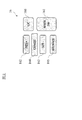
- FIG. 3 is a block diagram of the map database 13 and the control device 18.
- the control device 18 has a first memory 18a, a second memory 18b, a data acquisition unit 18c, and a travel control unit 18d.
- the first memory 18a is a memory that temporarily stores the data acquired from the map database 13.
- the storage capacity of the first memory 18a is smaller than the storage capacity of the map database 13.
- the second memory 18b is a memory that temporarily stores the data acquired from the first memory 18a.
- the storage capacity of the second memory 18b is smaller than the storage capacity of the first memory 18a.
- the data acquisition unit 18c is a functional block of the driving information acquisition function.
- the data acquisition unit 18c saves and deletes the first memory 18a and the second memory 18b. Further, the data acquisition unit 18c acquires data necessary for autonomous control from the data stored in the second memory 18b according to the traveling state of the own vehicle, and outputs the data to the traveling control unit 18d.
- the travel control unit 18d is a functional block of the autonomous travel control function.
- the map database 13 stores data of a specific area such as all over Japan.
- the data stored in the map database 13 is used for route search in the navigation system.
- the data acquisition unit 18c stores the road information within a predetermined range with respect to the current position of the own vehicle in the first memory 18a among the map information stored in the map database 13.
- the data acquisition unit 18c stores the road information from the current position of the own vehicle to a predetermined distance (for example, 2 km) ahead in the first memory 18a.
- the vehicle information stored in the first memory 18a is information such as a lane center line, a lane mark (white line), a speed limit, and a sign.
- the data acquisition unit 18c stores the road information in a predetermined range with respect to the current position of the own vehicle in the second memory 18b among the road information stored in the first memory 18a.
- the data acquisition unit 18c stores the road information from the current position of the own vehicle to a predetermined distance (for example, 1 km) ahead in the second memory 18b.
- a predetermined distance for example, 1 km
- the predetermined distance to be stored in the memory is the second memory 18b rather than the first memory 18a. Is shorter.
- the data acquisition unit 18c acquires only the road information necessary for autonomous control from the road information stored in the second memory 18b, and outputs it to the travel control unit 18d. At this time, if the travel road of the vehicle can be limited among the plurality of lanes, the data acquisition unit 18c selectively acquires the road information of the road on which the vehicle travels and outputs it to the travel control unit 18d. .. In other words, the data acquisition unit 18c extracts the road information stored in the second memory 18b when the traveling road of the vehicle can be limited among the plurality of vehicles, and transmits the extracted road information to the traveling control unit 18d. Output.
- the data acquisition unit 18c limits the driving road of the vehicle from a plurality of lanes based on the driver's operation and / or the traveling route. For example, when the road ahead of the current position of the own vehicle is branched and the driver operates the blinker and blinks the blinker lamp on the left side, the data acquisition unit 18c will perform the road on the left side of the branched roads. Limited to.
- the case where the vehicle leaves the tollhouse from the highway and heads for the general road is set and the own vehicle is approaching the interchange will be explained as an example.
- the vehicle The driving road can be limited.
- the road information of the main line and the road information of the branched road are stored in the second memory 18b, and the data acquisition unit 18c selectively selects the road information of the branched road due to the blinking of the winker. And outputs the selected road information to the travel control unit 18d.
- Road information is selectively acquired and output to the traveling control unit 18d. Since the road information of the lane that is not related to the autonomous control of the own vehicle is not input to the travel control unit 18d and the road information necessary for the autonomous control of the own vehicle is input, the calculation load in the travel control unit 18d is increased. Can be reduced.
- the autonomous driving control function of the control device 18 is a function that autonomously controls the driving of the own vehicle without depending on the operation of the driver.
- the autonomous driving speed control function that autonomously controls the traveling speed of the own vehicle and the steering of the own vehicle are autonomous. Includes an autonomous steering control function to control.
- the autonomous speed control function and the autonomous steering control function of the present embodiment will be described.
- the autonomous speed control function detects a preceding vehicle, it follows the preceding vehicle while performing inter-vehicle distance control so as to maintain the inter-vehicle distance according to the vehicle speed, with the vehicle speed set by the driver as the upper limit.
- the vehicle is not detected, it is a function to drive at a constant speed at the vehicle speed set by the driver.
- the former is also called inter-vehicle distance control, and the latter is also called constant speed control.
- the function of automatically setting the speed of the speed limit sign to the set vehicle speed may be included.
- the driver To activate the autonomous speed control function, the driver first operates the resume accelerator switch 162 or the set coast switch 163 of the input device 16 shown in FIG. 2 to input a desired traveling speed. For example, if the own vehicle is running at 70 km / h and the set coast switch 163 is pressed, the current running speed is set as it is, but if the speed desired by the driver is 80 km / h, resume acceleration The set speed may be increased by pressing the switch 162 multiple times. On the contrary, assuming that the speed desired by the driver is 60 km / h, the set coast switch 163 may be pressed a plurality of times to lower the set speed.
- inter-vehicle distance desired by the driver may be selected by operating the inter-vehicle adjustment switch 165 of the input device 16 shown in FIG. 2 and selecting one from a plurality of stages of settings such as short distance, medium distance, and long distance.
- the constant speed control uses a sensor 11 such as a front radar that detects an obstacle in front of the own vehicle to detect that there is no preceding vehicle in front of the lane in which the own vehicle is traveling, and the driving is set by the driver.
- the drive control device 17 controls the operation of the drive mechanism such as the engine and the brake while feeding back the vehicle speed data from the vehicle speed sensor so as to maintain the speed.
- the inter-vehicle distance control is based on the presence of a preceding vehicle (the vehicle immediately in front of the own vehicle) in front of the lane in which the own vehicle is traveling by using a sensor 11 such as a front radar that detects an obstacle in front of the own vehicle and the inter-vehicle distance.
- the drive control device 17 feeds back the inter-vehicle distance data from the sensor 11 (front radar) so as to maintain the inter-vehicle distance set by the driver with the traveling speed set by the driver as the upper limit while detecting the above. It controls the operation of drive mechanisms such as the engine and brakes.
- the own vehicle also stops following the preceding vehicle, and if the preceding vehicle starts within 30 seconds after the own vehicle stops, the own vehicle also starts. , Starts follow-up driving by inter-vehicle distance control again. If your vehicle has stopped for more than 30 seconds, it will not start automatically even if the preceding vehicle starts, and if you press the resume acceleration switch 162 or depress the accelerator pedal after the preceding vehicle starts. , Starts follow-up driving by inter-vehicle distance control again.
- the autonomous steering control function is a function that executes steering control of the own vehicle by controlling the operation of the steering actuator.
- a lane keeping function (lane width direction maintenance function) that controls the steering to drive near the center of the lane and assists the driver in steering, and controls the steering when the driver operates the winker lever, which is necessary for changing lanes.
- Lane change support function that supports various steering operations, when a vehicle slower than the set vehicle speed is detected ahead, the display confirms whether to overtake the driver, and if the driver operates the consent switch, the steering is controlled and the overtaking operation is performed.
- the driver will be asked if he / she will change lanes.
- the route driving support function is a function that controls the steering, vehicle speed, and blinker so that the own vehicle travels along the traveling route when the traveling route to the destination is set.
- FIG. 4A is a diagram for explaining a traveling locus and a target point when a vehicle travels from the main lane to the branch lane on a branch road.
- FIG. 4B is a schematic view showing a part of the traveling locus and the target point of FIG. 4A.
- the X-axis shows the coordinate axes in the lateral direction (vehicle width direction) of the vehicle
- the Y-axis shows the coordinate axes in the vehicle traveling direction on the main line.
- lane A is a branch lane connecting the main lane to the tollhouse.
- the main lane includes lanes B and C, and lane C is the overtaking lane.
- the control device 180 calculates the travel route to the destination.
- the control device 180 executes a lane keeping function and a lane change function in order to travel according to the traveling route.
- the control device 180 executes each function based on the information recognized by the camera image and the map information stored in the database 13. Since the information that can be recognized by the camera image indicates the actual driving environment, when the lane mark can be recognized from the camera image, the control device 180 preferentially uses the information recognized from the camera image to vehicle the vehicle. Autonomously control. In the branch road as shown in FIG. 4A, a dotted boundary line is drawn between the main lane and the branch lane, but many vehicles heading from the main lane to the branch lane travel across this boundary line.
- the control device 180 autonomously controls the vehicle based on the map information stored in the database 13.
- an area where a feature to be recognized for autonomous control, such as a lane mark and / or an obstacle, cannot be recognized from the camera image is specified in advance as an unrecognizable area.
- the unrecognizable area indicates an area where the external situation of the vehicle cannot be recognized by the camera image.
- Information on the size and position of the unrecognizable area is stored in advance in the map database 13.
- the control device 180 refers to the map database 13 and determines whether or not there is an unrecognizable area on the travel route calculated by the vehicle. If the unrecognizable area is on the travel route, the vehicle will travel in the unrecognizable area. In the unrecognizable area, the lane keeping function cannot be activated by using the information recognized from the camera image.
- the control device 180 uses the road information stored in the map database instead of the camera image to lane. Execute the keep function and / or the lane change function. That is, when the vehicle is not traveling in the unrecognizable area, the control device 180 autonomously controls the vehicle using the information recognized from the camera image, and when traveling in the unrecognizable area, the control device 180 is the camera. Instead of images, the road information stored in the map database is used to autonomously control the vehicle.
- the center line of the lane included in the map information is used as the traveling locus of the vehicle.
- the target point is set at a position separated from the current position of the own vehicle by a predetermined traveling time (for example, 1.25 seconds).
- a predetermined traveling time for example, 1.25 seconds.
- the autonomous control based on the camera image is switched to the autonomous control based on the map information before the vehicle enters the unrecognizable area. ing.
- the control device 180 specifies a predetermined area R including the branch path as an unrecognizable area.
- the unrecognizable area A includes at least a boundary line between the main lane and the branch lane and a part of the branch lane.
- the control device 180 sets the lane change start point P because it is necessary to change lanes from the main lane to the branch lane at the branch road of the interchange.
- the lane change start point is a point at which steering control is started so that the vehicle moves in the lateral direction (vehicle width direction).
- the control device 180 sets the lane change start point P on the lane B.
- the lane change start point P is set at a position in front of the point O where the branch lane starts by a predetermined distance.
- the lane change start point P is set on lane B.
- the lane change start points are set on lane B and lane C, respectively.
- the distance from the lane change start point set on lane C to the lane change start point set on lane B is the direction of travel of the vehicle, and the branch lane starts from the lane change start point set on lane B.
- the distance is set longer than the distance to the point O.
- the control device 180 sets an intention confirmation point Q for confirming the user's intention to change lanes at a position a predetermined distance before the lane change start point P.
- the control device 180 confirms with the driver whether to change lanes by displaying the display.
- the data acquisition unit 18c of the control device 180 acquires the road information of the lane A, which is a branch lane, and does not acquire the road information of the lanes B and C.
- the data acquisition unit 18c of the control device 180 acquires the road information of the lane A, which is a branch lane, and the roads of the lanes B and C. Do not get information.
- the timing at which the data acquisition unit 18c of the control device 180 acquires the road information of the lane A may be at the start of blinking of the blinker or after the start of blinking of the blinker. Since the blinker starts blinking when the own vehicle reaches the lane change start point P, the data acquisition unit 18c of the control device 180 may acquire the information of the lane A in accordance with the blinking of the blinker. ..
- Lane B is the same road on which the vehicle is currently traveling.
- the control device 180 uses the lane keeping function to recognize the lane mark from the camera image and then controls the steering so as to travel near the center of the lane B. Then, when the intention to change lanes is confirmed and the own vehicle reaches the lane change start point P, the control device 180 recognizes the lane mark from the camera image by the lane change support function, and then changes the lane.
- the steering is controlled so that the position of the vehicle passes through the target point on the traveling locus. As a result, the vehicle moves laterally so that the distance between the current position of the vehicle and the lane mark on the right side increases.
- the control device 180 sets a control switching point at the branch road while executing the camera control in preparation for switching from the camera control to the map control.
- the control switching points are, for example, the center line between the left and right lane marks recognized from the camera image (or an extension line obtained by extending the center line) and the lane included in the map information (the lane including the branch lane). It is set at the intersection with the center line (or an extension line that extends the center line).
- the control switching point is set at a position where the lateral deviation from the extended line (extended line) is less than a predetermined length.
- the control switching point is outside the unrecognizable area and is set at a position on the center line of the lane B.
- the control switching point is set at the position of the lane change start point P.
- the control device 180 switches from camera control to map control.
- autonomous control of the vehicle is executed so that the vehicle travels along the center line of the lane included in the road information A, and the vehicle travels on the branch lane.
- the control device 180 calculates the timing for switching from map control to camera control while the vehicle is traveling in the unrecognizable area or after the vehicle has passed the unrecognizable area.
- the control device 180 calculates a target point (hereinafter, also referred to as a first target point) using a camera image while traveling in the unrecognizable area or after passing through the unrecognizable area. If the lane mark cannot be stably recognized from the camera image in the unrecognizable area, the first target point is calculated after the lane mark can be recognized. Further, the control device 180 calculates a target point (hereinafter, also referred to as a second target point) using the road information A. Then, the control device 180 switches from map control to camera control when the difference between the first target point and the second target point is equal to or less than a predetermined value.
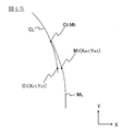
- the curve C L represents the running locus is calculated from the camera image
- the curve M L represents the running locus is calculated from the map information (road information A).
- the first target point C is represented by the position (X c , Y c )
- the second target point M is represented by the position (X M , Y M ).
- the angle ( ⁇ C ) of the angle formed by the line segment connecting the origin and the first target point C and the X axis is calculated.
- the current position of the vehicle is set as the origin
- the angle ( ⁇ M ) of the angle formed by the line segment connecting the origin and the second target point M and the X axis is calculated.
- the angle ( ⁇ C , ⁇ M ) is calculated by the following equations (1) and (2).
- the control device 180 determines whether or not the condition of the following equation (3) is satisfied.
- control device 180 switches from map control to camera control and autonomously makes the vehicle so that the position of the vehicle passes the first target point. Control.
- the angle ( ⁇ C1 ) calculated with respect to the first target point C 1 and the angle ( ⁇ M1 ) calculated with respect to the second target point M 1 and the difference are threshold values ( ⁇ th). ) Greater. Therefore, at the timing when the second target point M 1 is calculated, the control device 180 continues the map control. The angle ( ⁇ C2 ) calculated with respect to the first target point C 2 and the angle ( ⁇ M2 ) calculated with respect to the second target point M 2 and the difference are smaller than the threshold value ( ⁇ th ). Therefore, the control device 180 switches from map control to camera control at the timing when the own vehicle passes the first target point C 2 . As a result, it is possible to prevent the behavior of the vehicle from becoming large when switching from map control to camera control.
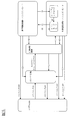
- FIG. 5 is a block diagram showing a state transition of each function established in the control device 18.
- the system means an autonomous driving control system realized by the control device 18.
- the main switch 161 of FIG. 2 When the main switch 161 of FIG. 2 is turned on from the system OFF state shown in the figure, the system goes into the standby state. From this standby state, the autonomous speed control is activated by turning on the set coast switch 163 or the resume acceleration switch 162 of FIG.
- the above-mentioned constant speed control or inter-vehicle distance control is started, and the driver can drive his / her own vehicle simply by operating the steering wheel without stepping on the accelerator or the brake.
- the mode transitions to the lane keep mode of the autonomous steering control / hands-on mode.
- the condition (1) is not particularly limited, but the lane marks on both sides of the own vehicle are detected, the driver has the steering wheel, the vehicle is traveling near the center of the lane, and the winker is activated. Not doing, the wiper is not operating at high speed (HI), if there is a high-precision map, there are no tollhouses, exits, confluences, intersections, lane reduction points, etc. within about 200 m ahead. It can be illustrated that the conditions are satisfied.
- the hands-on mode refers to a mode in which the autonomous steering control does not operate unless the driver holds the steering wheel
- the hands-off mode refers to a mode in which the autonomous steering control operates even if the driver releases the steering wheel.
- condition (2) in FIG. 5 If the condition (2) in FIG. 5 is satisfied while the lane keep mode of the autonomous steering control / hands-on mode is being executed, the mode transitions to the lane keep mode of the autonomous steering control / hands-off mode.
- the condition (2) is not particularly limited, but the vehicle is traveling on a motorway, is traveling on a road structurally separated from the oncoming lane, and is traveling on a road having a high-precision map. You must be driving, you are driving at a vehicle speed below the speed limit, the GPS signal is valid, the driver has a handle, the driver is facing forward, and the toll booth is within about 800 m ahead.
- condition (3) of FIG. 5 is satisfied while the lane keep mode of the autonomous steering control / hands-off mode is being executed, the mode transitions to the lane keep mode of the autonomous steering control / hands-on mode.
- the condition (3) is not particularly limited, but the vehicle is traveling on a road other than a motorway, is traveling on a two-way traffic section, and is traveling on a road without a high-precision map.
- condition (4) in FIG. 5 is satisfied while the lane keep mode of the autonomous steering control / hands-off mode is being executed, the autonomous steering control is stopped and the process shifts to the autonomous speed control.
- the condition (4) is not particularly limited, but one of the following is that the lane marks on both sides of the own vehicle are not detected for a certain period of time, the driver operates the steering wheel, and the wiper operates at high speed (HI). It can be illustrated that the condition of is satisfied. Further, if the condition (5) of FIG. 5 is satisfied while the lane keep mode of the autonomous steering control / hands-off mode is being executed, the autonomous steering control and the autonomous speed control are stopped and the state shifts to the standby state.
- the condition (5) is not particularly limited, but the driver operates the brake, the driver operates the cancel switch 164 in FIG. 2, the door of the own vehicle is opened, and the driver's seat belt is released. That, the seating sensor detected that the driver had left the driver's seat, the select lever was other than "D” or "M”, the parking brake was activated, and the vehicle's electronic stability control was turned off. , The electronic stability control has been activated, the snow mode has been turned on, the emergency brake has been activated, the vehicle has stopped due to vehicle speed control, and the vehicle has been stopped for about 3 minutes. However, it detected poor visibility such as dirt, backlight, rain / fog, etc.
- the front radar detected shielding, radio interference, the front radar detected misalignment, and the side radar It can be exemplified that any of the conditions such as shielding, detection of radio interference, and detection of axis deviation by the side radar is satisfied.
- condition (6) in FIG. 5 is satisfied while the autonomous steering control / hands-on mode is being executed, the autonomous steering control is stopped and the process shifts to the autonomous speed control.
- the condition (6) is not particularly limited, but the lane marks on both sides of the own vehicle are no longer detected, the driver operates the steering wheel, the driver operates the blinker, and the wiper operates at high speed (HI).
- HI high speed
- One of the conditions was that the vehicle was in the tollhouse section when there was a high-precision map, and that the front camera detected poor visibility that could not correctly recognize the object due to dirt, backlight, rain, fog, etc. It can be illustrated that it is established. Further, if the condition (7) of FIG.
- the condition (7) is not particularly limited, but the driver operates the brake, the driver operates the cancel switch 164 in FIG. 2, the door of the own vehicle is opened, and the driver's seat belt is released. That, the seating sensor detected that the driver had left the driver's seat, the select lever was other than "D" or "M”, the parking brake was activated, and the vehicle's electronic stability control was turned off. , The electronic stability control was activated, the snow mode was turned on, the emergency brake was activated, the vehicle stopped due to vehicle speed control, and then the stopped state continued for about 3 minutes, front radar. It can be exemplified that any of the conditions such as shielding, detection of radio interference, and detection of axis deviation by the front radar is satisfied.
- the condition (8) in FIG. 5 is satisfied while the autonomous speed control is being executed, the state transitions to the standby state.
- the condition (8) is not particularly limited, but the driver operates the brake, the driver operates the cancel switch 164 in FIG. 2, the door of the own vehicle is opened, and the driver's seat belt is released. That, the seating sensor detected that the driver had left the driver's seat, the select lever was other than "D” or "M”, the parking brake was activated, and the vehicle's electronic stability control was turned off. , The electronic stability control was activated, the snow mode was turned on, the emergency brake was activated, the vehicle stopped due to vehicle speed control, and the stopped state continued for about 3 minutes, front radar. It can be exemplified that any of the conditions such as shielding, detection of radio interference, and detection of axis deviation by the front radar is satisfied.
- condition (9) in FIG. 5 is satisfied while the lane keep mode of the autonomous steering control / hands-off mode is being executed, the mode transitions to the lane change mode of the autonomous steering control / hands-on mode.
- This condition (9) is not particularly limited, but is one of the conditions that the driver presses the lane change support switch 166 in FIG. 2 and the driver operates the blinker when the system proposes a lane change. Can be exemplified as the establishment of.
- condition (10) in FIG. 5 is satisfied while the lane change mode of the autonomous steering control / hands-on mode is being executed, the mode transitions to the lane keep mode of the autonomous steering control / hands-on mode.
- the condition (10) is not particularly limited, but the speed limit is exceeded before the start of the lane change operation (hereinafter referred to as LCP), and the driver holds the steering wheel and depresses the accelerator pedal before the start of the LCP.
- LCP could not be started within 10 seconds after pressing the lane change support switch 166 during the lane change proposal when there was a slow vehicle ahead, and the lane change support switch during the lane change proposal to drive according to the route.
- the main switch 161 is turned off in any of the autonomous steering control / hands-off mode, the autonomous steering control / hands-on mode, the autonomous speed control, and the standby state, the system is turned off.
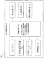
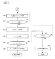
- FIGS. 6A to 6C are flowcharts showing the traveling control process according to the present embodiment.
- the travel control process described below is executed by the control device 18 at predetermined time intervals.
- the autonomous driving control function of the control device 18 executes autonomous speed control and autonomous steering control, and the width direction of the own vehicle so that the own vehicle travels in the lane at a speed set by the driver. While the lane keep control for controlling the traveling position in the above is being performed, it is assumed that the interchange is approaching and the vehicle is traveling on a route that requires a lane change in order to travel according to the traveling route.
- step S1 of FIG. 6A it is determined whether or not the main switch 161 of the control device 18 is ON, and if the main switch 161 is OFF, step S1 is repeated until it is turned ON. If the main switch 161 is ON, the process proceeds to step S2, and it is determined whether or not the traveling speed is set by the driver. If the traveling speed is not set, the process returns to step S1 and steps S1 and S2 are repeated until the traveling speed is set. The traveling speed is set by the driver by operating the resume acceleration switch 162 or the set coast switch 163 of the input device 16 shown in FIG. 2 to input a desired traveling speed.
- step S3 the front radar (sensor 11) that detects an obstacle in front of the own vehicle is used to detect whether or not there is a preceding vehicle in front of the lane in which the own vehicle is traveling, and if there is a preceding vehicle. Proceeds to step S4 to execute inter-vehicle distance control, and if there is no preceding vehicle, proceeds to step S5 to execute constant speed control.
- the driver can drive the own vehicle at a desired speed simply by operating the steering wheel without stepping on the accelerator or the brake.
- step S6 Whether or not the condition (1) for transitioning to the above-mentioned autonomous steering control / hands-on mode lane keep mode is satisfied in step S6 while the inter-vehicle distance control in step S4 or the constant speed control in step S5 is being executed. To judge. If the condition (1) is satisfied, the process proceeds to step S7, and if the condition (1) is not satisfied, the process returns to step S2.
- step S7 the front radar (sensor 11) that detects an obstacle in front of the own vehicle is used to detect whether or not there is a preceding vehicle in front of the lane in which the own vehicle is traveling, and if there is a preceding vehicle. Proceeds to step S8 to execute the inter-vehicle distance control / lane keep mode, and if there is no preceding vehicle, proceeds to step S9 to execute the constant speed control / lane keep mode.
- the autonomous control in step S8 or step S9 is a control based on a camera image.
- step S10 of FIG. 6B While the inter-vehicle distance control / lane keep mode in step S8 or the constant speed control / lane keep mode in step S9 is being executed, it is determined in step S10 of FIG. 6B that the destination is set. If the destination has not been set, the process returns to step S2 of FIG. 6A. If the destination has been set, the process proceeds to step S11 to execute route traveling support. In route driving support, when it is necessary to change lanes in order to drive according to the driving route, a lane change start point and an intention confirmation point for confirming the intention to change lanes are set. In step S12, the map information stored in the map database 13 is referred to, and an unrecognizable area is specified on the traveling route.
- step S13 it is determined whether or not the current position of the vehicle has reached the intention confirmation point, and if it has not reached the intention confirmation point, the process returns to step S11, and if it reaches the intention confirmation point, the lane is changed.
- a display screen is displayed on the display to confirm the driver's intention as to whether or not to do so.
- step S14 it is determined whether or not there is an intention to change lanes. After the display is displayed, if the driver operates the consent switch, it is determined that there is an intention to change lanes, and the process proceeds to step S15. If the consent switch is not operated, it is determined that there is no intention to change lanes. , Step S18.
- step S15 it is determined whether or not the lane changeable condition is satisfied.
- the lane changeable condition is the condition shown in FIG. 5 (9). However, if the conditions of FIG. 5 (9) include the recognition of the lane mark and the space of the adjacent lane required for changing lanes, the lane set in the determination process of step S15. These conditions are excluded from the modifiable conditions. If the lane changeable condition is satisfied, the process proceeds to step S16, and if the lane changeable condition is not satisfied, the process proceeds to step S19.
- step S16 it is determined whether or not the current position of the vehicle has reached the lane change start point, and if the vehicle has reached the lane change start point, the process proceeds to step S17, and if the vehicle has not reached the lane change start point, the process proceeds to step S17. Return to step S16. If the vehicle does not follow the travel route before reaching the lane change start point (for example, when the vehicle moves to a lane adjacent to the current lane), the process proceeds to step S19.
- step S17 the control device 180 starts blinking the blinker.
- step S18 the control device 180 acquires the road information of lane A, which is a branch lane, from the road information stored in the second memory 18b, and proceeds to step S20. If the current position of the vehicle reaches the intention confirmation point or the lane change start point and the information on the branch lane has already been acquired, the road information of the lane A ahead of the already acquired branch lane is acquired. To do.
- step S19 the control device 180 acquires the road information of the main lanes B and C among the road information stored in the second memory 18b, and returns to step S2 of FIG. 6A.
- step S20 the autonomous control based on the camera image is switched to the autonomous control based on the map information, and the lane change support is executed.
- the lane change support in step S20 is executed in the hands-on mode.
- the target point M is calculated using the road information of the lane A, and the steering is controlled so that the vehicle passes the target point M.
- the calculation of the target point M is repeated at a predetermined cycle, and the steering is controlled so that the vehicle passes each of the calculated target points M.
- step S21 it is determined whether or not the lane mark can be recognized from the camera image, and if the lane mark can be recognized, the process proceeds to step S22, and if the lane mark cannot be recognized, the process returns to step S20.
- the determination timing in step S21 may be performed after a predetermined time has elapsed from the time when the autonomous control based on the camera image is switched to the autonomous control based on the map information, for example.
- the length of the predetermined time may be set to be equal to or longer than the length of time from the start to the completion of the lane change.
- step S22 the target points C and M are calculated. That is, the target point C is calculated in addition to the target point M.
- step S23 the angle ( ⁇ C , ⁇ M ) is calculated.
- step S24 the difference between the first target point and the second target point (
- the autonomous control based on the map information is switched to the autonomous control based on the camera image (S29).
- the lane change in the branch road is completed, and the autonomous control based on the map information is switched to the autonomous control based on the camera image while the vehicle is traveling in the branch lane.
- ) when a is larger than the threshold value ([Delta] [theta] th) is the threshold value ([Delta] [theta] th) larger than the state given It is determined whether or not the time (for example, 10 seconds) has elapsed. If the predetermined time (for example, 10 seconds) has not elapsed, the process returns to step S22, and if the predetermined time (for example, 10 seconds) has elapsed, the autonomous steering control is turned off and the steering operation is switched to the driver.
- the time for example, 10 seconds
- step S20 Since the control flow after step S20 is executed in the hands-on mode, when the automatic steering control is turned off in step S27, the driver is holding the steering wheel, and the driver can smoothly perform the steering operation.
- the difference between the first target point (target point C) and the second target point (target point M) is large. If you switch from map control to camera control in this state, the behavior of the vehicle will increase. Therefore, in the present embodiment, when the difference between the first target point (target point C) and the second target point (target point M) is large for a predetermined time or longer, the autonomous steering control is turned off. Therefore, it is possible to prevent the behavior of the vehicle from becoming large when the control is switched.
- the vehicle travel control device 1 and the travel control method according to the present embodiment when the unrecognizable area is on the travel route of the vehicle, before the vehicle enters the unrecognizable area. , Switch from autonomous control based on camera images (corresponding to "first autonomous control” of the present invention) to autonomous control based on map information (corresponding to "second autonomous control” of the present invention).
- the autonomous control based on the camera image is the autonomous control of the vehicle using the information recognized from the camera image
- the autonomous control based on the map information is the autonomous control of the vehicle using the map information of the map database 13.
- the difference between the first target point and the second target point is equal to or less than a predetermined value after switching from the first autonomous control to the second autonomous control.
- the second autonomous control is switched to the first autonomous control.
- the difference between the first target point and the second target point is larger than the predetermined value after switching from the first autonomous control to the second autonomous control. If the state continues for a predetermined time or longer, the autonomous steering control function is turned off. As a result, it is possible to prevent the map control from being switched to the camera control in a state where the difference between the first target point and the second target point is large, and to prevent the behavior of the vehicle from becoming large.
- the difference between the first target point and the second target point is larger than the predetermined value after switching from the first autonomous control to the second autonomous control. In that case, the second autonomous control is continued. As a result, it is possible to prevent the map control from being switched to the camera control in a state where the difference between the first target point and the second target point is large, and to prevent the behavior of the vehicle from becoming large.
Landscapes
- Engineering & Computer Science (AREA)
- Mechanical Engineering (AREA)
- Automation & Control Theory (AREA)
- Transportation (AREA)
- Human Computer Interaction (AREA)
- Physics & Mathematics (AREA)
- General Physics & Mathematics (AREA)
- Combustion & Propulsion (AREA)
- Chemical & Material Sciences (AREA)
- Multimedia (AREA)
- Theoretical Computer Science (AREA)
- Traffic Control Systems (AREA)
- Control Of Driving Devices And Active Controlling Of Vehicle (AREA)
- Steering Control In Accordance With Driving Conditions (AREA)
Abstract
La présente invention utilise une fonction de commande de vitesse autonome qui commande de manière autonome la vitesse de déplacement d'un véhicule et une fonction de commande de direction autonome qui commande de manière autonome la direction du véhicule pour commander de manière autonome le véhicule, et lorsqu'il est possible de reconnaître l'état externe du véhicule à l'aide d'une image capturée d'une caméra disposée sur le véhicule, utilise les informations reconnues à partir de l'image capturée pour exécuter une première commande autonome pour commander de manière autonome le véhicule, acquiert des informations indiquant l'état externe du véhicule à partir d'informations cartographiques stockées dans un support de stockage fourni dans le véhicule, utilise les informations acquises pour exécuter une seconde commande autonome pour commander de manière autonome le véhicule, identifie une zone non reconnaissable pour laquelle l'état externe du véhicule ne peut pas être reconnu à l'aide de l'image capturée, et lorsque la zone non reconnaissable se trouve sur l'itinéraire de déplacement du véhicule, commute de la première commande autonome à la seconde commande autonome avant que le véhicule ne pénètre dans la zone non reconnaissable.
Priority Applications (4)
| Application Number | Priority Date | Filing Date | Title |
|---|---|---|---|
| EP20805045.0A EP3971866B1 (fr) | 2019-05-15 | 2020-04-21 | Procédé et dispositif de commande de déplacement de véhicule |
| US17/609,847 US11926320B2 (en) | 2019-05-15 | 2020-04-21 | Vehicle travel control method and vehicle travel control device |
| CN202080035779.4A CN113826153B (zh) | 2019-05-15 | 2020-04-21 | 车辆的行驶控制方法及行驶控制装置 |
| JP2021519331A JP7347503B2 (ja) | 2019-05-15 | 2020-04-21 | 車両の走行制御方法及び走行制御装置 |
Applications Claiming Priority (2)
| Application Number | Priority Date | Filing Date | Title |
|---|---|---|---|
| JP2019092431 | 2019-05-15 | ||
| JP2019-092431 | 2019-05-15 |
Publications (1)
| Publication Number | Publication Date |
|---|---|
| WO2020230551A1 true WO2020230551A1 (fr) | 2020-11-19 |
Family
ID=73289971
Family Applications (1)
| Application Number | Title | Priority Date | Filing Date |
|---|---|---|---|
| PCT/JP2020/017234 WO2020230551A1 (fr) | 2019-05-15 | 2020-04-21 | Procédé et dispositif de commande de déplacement de véhicule |
Country Status (5)
| Country | Link |
|---|---|
| US (1) | US11926320B2 (fr) |
| EP (1) | EP3971866B1 (fr) |
| JP (1) | JP7347503B2 (fr) |
| CN (1) | CN113826153B (fr) |
| WO (1) | WO2020230551A1 (fr) |
Cited By (2)
| Publication number | Priority date | Publication date | Assignee | Title |
|---|---|---|---|---|
| JP7376634B2 (ja) | 2022-03-22 | 2023-11-08 | 本田技研工業株式会社 | 車両制御装置、車両制御方法、およびプログラム |
| JP7449971B2 (ja) | 2022-03-25 | 2024-03-14 | 本田技研工業株式会社 | 車両制御装置、車両制御方法、およびプログラム |
Families Citing this family (8)
| Publication number | Priority date | Publication date | Assignee | Title |
|---|---|---|---|---|
| CN110018632B (zh) * | 2018-06-22 | 2020-10-09 | 长城汽车股份有限公司 | 一种车辆变道控制方法和装置 |
| JP7238707B2 (ja) * | 2019-09-09 | 2023-03-14 | トヨタ自動車株式会社 | 車両運転支援装置 |
| KR20210114689A (ko) * | 2020-03-11 | 2021-09-24 | 주식회사 만도 | 차량 및 그 제어 방법 |
| JP2022060077A (ja) * | 2020-10-02 | 2022-04-14 | 株式会社Subaru | 自動操舵制御装置 |
| JP7225185B2 (ja) * | 2020-11-26 | 2023-02-20 | 本田技研工業株式会社 | 車両制御装置、車両制御方法、およびプログラム |
| FR3120041B1 (fr) * | 2021-02-23 | 2023-01-06 | Psa Automobiles Sa | Procede et dispositif de determination d’une consigne de deceleration d’un vehicule autonome |
| US20230150494A1 (en) * | 2021-11-16 | 2023-05-18 | GM Global Technology Operations LLC | System and methods for engagement in hands-off lane centering applications |
| CN114312838B (zh) * | 2021-12-29 | 2023-07-28 | 上海洛轲智能科技有限公司 | 一种车辆的控制方法、装置及存储介质 |
Citations (5)
| Publication number | Priority date | Publication date | Assignee | Title |
|---|---|---|---|---|
| JP2010083312A (ja) * | 2008-09-30 | 2010-04-15 | Fuji Heavy Ind Ltd | 車両の運転支援装置 |
| JP2017041070A (ja) * | 2015-08-19 | 2017-02-23 | ソニー株式会社 | 車両制御装置と車両制御方法と情報処理装置および交通情報提供システム |
| JP2018073010A (ja) * | 2016-10-26 | 2018-05-10 | パイオニア株式会社 | 移動体制御装置、移動体制御方法、および、移動体制御装置用プログラム |
| JP2019038396A (ja) | 2017-08-25 | 2019-03-14 | 株式会社Subaru | 車両の運転支援装置 |
| JP2019092431A (ja) | 2017-11-22 | 2019-06-20 | 小橋工業株式会社 | 農作業機 |
Family Cites Families (9)
| Publication number | Priority date | Publication date | Assignee | Title |
|---|---|---|---|---|
| TWI453615B (zh) * | 2011-11-25 | 2014-09-21 | 智慧型行車紀錄與檢視系統 | |
| CN104411558B (zh) | 2012-07-06 | 2017-09-22 | 丰田自动车株式会社 | 车辆的行驶控制装置 |
| JP6410655B2 (ja) * | 2015-03-31 | 2018-10-24 | アイシン・エィ・ダブリュ株式会社 | 道路形状検出システム、道路形状検出方法及びコンピュータプログラム |
| JP6474307B2 (ja) * | 2015-04-27 | 2019-02-27 | アイシン・エィ・ダブリュ株式会社 | 自動運転支援システム、自動運転支援方法及びコンピュータプログラム |
| CN107560622A (zh) * | 2016-07-01 | 2018-01-09 | 板牙信息科技(上海)有限公司 | 一种基于行车图像导航的方法与设备 |
| KR102581359B1 (ko) * | 2016-09-02 | 2023-09-20 | 엘지전자 주식회사 | 차량용 사용자 인터페이스 장치 및 차량 |
| US10606276B2 (en) * | 2016-09-30 | 2020-03-31 | Faraday & Future Inc. | User data-based autonomous vehicle system |
| JP2019043432A (ja) * | 2017-09-05 | 2019-03-22 | 本田技研工業株式会社 | 車両制御システム、車両制御方法、およびプログラム |
| KR20190063845A (ko) * | 2017-11-30 | 2019-06-10 | 삼성전자주식회사 | 차로 유지 보조 방법 및 장치 |
-
2020
- 2020-04-21 WO PCT/JP2020/017234 patent/WO2020230551A1/fr unknown
- 2020-04-21 JP JP2021519331A patent/JP7347503B2/ja active Active
- 2020-04-21 CN CN202080035779.4A patent/CN113826153B/zh active Active
- 2020-04-21 EP EP20805045.0A patent/EP3971866B1/fr active Active
- 2020-04-21 US US17/609,847 patent/US11926320B2/en active Active
Patent Citations (5)
| Publication number | Priority date | Publication date | Assignee | Title |
|---|---|---|---|---|
| JP2010083312A (ja) * | 2008-09-30 | 2010-04-15 | Fuji Heavy Ind Ltd | 車両の運転支援装置 |
| JP2017041070A (ja) * | 2015-08-19 | 2017-02-23 | ソニー株式会社 | 車両制御装置と車両制御方法と情報処理装置および交通情報提供システム |
| JP2018073010A (ja) * | 2016-10-26 | 2018-05-10 | パイオニア株式会社 | 移動体制御装置、移動体制御方法、および、移動体制御装置用プログラム |
| JP2019038396A (ja) | 2017-08-25 | 2019-03-14 | 株式会社Subaru | 車両の運転支援装置 |
| JP2019092431A (ja) | 2017-11-22 | 2019-06-20 | 小橋工業株式会社 | 農作業機 |
Cited By (2)
| Publication number | Priority date | Publication date | Assignee | Title |
|---|---|---|---|---|
| JP7376634B2 (ja) | 2022-03-22 | 2023-11-08 | 本田技研工業株式会社 | 車両制御装置、車両制御方法、およびプログラム |
| JP7449971B2 (ja) | 2022-03-25 | 2024-03-14 | 本田技研工業株式会社 | 車両制御装置、車両制御方法、およびプログラム |
Also Published As
| Publication number | Publication date |
|---|---|
| EP3971866A4 (fr) | 2022-07-06 |
| EP3971866A1 (fr) | 2022-03-23 |
| CN113826153B (zh) | 2024-01-02 |
| CN113826153A (zh) | 2021-12-21 |
| JP7347503B2 (ja) | 2023-09-20 |
| JPWO2020230551A1 (fr) | 2020-11-19 |
| US11926320B2 (en) | 2024-03-12 |
| EP3971866B1 (fr) | 2024-02-28 |
| US20220219692A1 (en) | 2022-07-14 |
Similar Documents
| Publication | Publication Date | Title |
|---|---|---|
| WO2020230551A1 (fr) | Procédé et dispositif de commande de déplacement de véhicule | |
| JP7143946B2 (ja) | 車両の走行制御方法及び走行制御装置 | |
| JP7140277B2 (ja) | 車両の走行制御方法及び走行制御装置 | |
| CN113811470B (zh) | 车辆的行驶控制方法及行驶控制装置 | |
| JP7331450B2 (ja) | 車両の走行制御方法及び走行制御装置 | |
| JP7156517B2 (ja) | 車両の走行制御方法及び走行制御装置 | |
| JP2021091282A (ja) | 車両の走行制御方法および走行制御装置 | |
| EP3971060B1 (fr) | Procédé et dispositif de commande de déplacement de véhicule | |
| EP4309969A1 (fr) | Procédé de commande de déplacement et dispositif de commande de déplacement pour un véhicule | |
| WO2022107277A1 (fr) | Procédé de commande de déplacement de véhicule et dispositif de commande de déplacement | |
| RU2792474C1 (ru) | Способ управления вождением и устройство управления вождением | |
| WO2023089837A1 (fr) | Procédé d'aide au déplacement et dispositif d'aide au déplacement pour véhicule | |
| WO2021106146A1 (fr) | Procédé de commande de déplacement et dispositif de commande de déplacement pour véhicule |
Legal Events
| Date | Code | Title | Description |
|---|---|---|---|
| 121 | Ep: the epo has been informed by wipo that ep was designated in this application |
Ref document number: 20805045 Country of ref document: EP Kind code of ref document: A1 |
|
| ENP | Entry into the national phase |
Ref document number: 2021519331 Country of ref document: JP Kind code of ref document: A |
|
| NENP | Non-entry into the national phase |
Ref country code: DE |
|
| ENP | Entry into the national phase |
Ref document number: 2020805045 Country of ref document: EP Effective date: 20211215 |