WO2021106146A1 - Procédé de commande de déplacement et dispositif de commande de déplacement pour véhicule - Google Patents
Procédé de commande de déplacement et dispositif de commande de déplacement pour véhicule Download PDFInfo
- Publication number
- WO2021106146A1 WO2021106146A1 PCT/JP2019/046584 JP2019046584W WO2021106146A1 WO 2021106146 A1 WO2021106146 A1 WO 2021106146A1 JP 2019046584 W JP2019046584 W JP 2019046584W WO 2021106146 A1 WO2021106146 A1 WO 2021106146A1
- Authority
- WO
- WIPO (PCT)
- Prior art keywords
- vehicle
- speed
- vehicle speed
- lane
- traveling
- Prior art date
Links
- 238000000034 method Methods 0.000 title claims abstract description 96
- 230000008859 change Effects 0.000 claims description 200
- 230000001133 acceleration Effects 0.000 claims description 75
- 230000007423 decrease Effects 0.000 claims description 4
- 230000006870 function Effects 0.000 description 197
- 230000008569 process Effects 0.000 description 52
- 238000001514 detection method Methods 0.000 description 21
- 238000012545 processing Methods 0.000 description 10
- 230000007704 transition Effects 0.000 description 8
- 239000003550 marker Substances 0.000 description 7
- 230000007246 mechanism Effects 0.000 description 6
- 238000003825 pressing Methods 0.000 description 5
- 238000010586 diagram Methods 0.000 description 4
- 238000002474 experimental method Methods 0.000 description 4
- 230000004044 response Effects 0.000 description 3
- 125000002066 L-histidyl group Chemical group [H]N1C([H])=NC(C([H])([H])[C@](C(=O)[*])([H])N([H])[H])=C1[H] 0.000 description 2
- 238000002485 combustion reaction Methods 0.000 description 2
- 238000013459 approach Methods 0.000 description 1
- 230000006399 behavior Effects 0.000 description 1
- 230000000994 depressogenic effect Effects 0.000 description 1
- 238000005516 engineering process Methods 0.000 description 1
- 230000009467 reduction Effects 0.000 description 1
Images


Classifications
-
- B—PERFORMING OPERATIONS; TRANSPORTING
- B60—VEHICLES IN GENERAL
- B60W—CONJOINT CONTROL OF VEHICLE SUB-UNITS OF DIFFERENT TYPE OR DIFFERENT FUNCTION; CONTROL SYSTEMS SPECIALLY ADAPTED FOR HYBRID VEHICLES; ROAD VEHICLE DRIVE CONTROL SYSTEMS FOR PURPOSES NOT RELATED TO THE CONTROL OF A PARTICULAR SUB-UNIT
- B60W30/00—Purposes of road vehicle drive control systems not related to the control of a particular sub-unit, e.g. of systems using conjoint control of vehicle sub-units
- B60W30/14—Adaptive cruise control
-
- B—PERFORMING OPERATIONS; TRANSPORTING
- B60—VEHICLES IN GENERAL
- B60W—CONJOINT CONTROL OF VEHICLE SUB-UNITS OF DIFFERENT TYPE OR DIFFERENT FUNCTION; CONTROL SYSTEMS SPECIALLY ADAPTED FOR HYBRID VEHICLES; ROAD VEHICLE DRIVE CONTROL SYSTEMS FOR PURPOSES NOT RELATED TO THE CONTROL OF A PARTICULAR SUB-UNIT
- B60W50/00—Details of control systems for road vehicle drive control not related to the control of a particular sub-unit, e.g. process diagnostic or vehicle driver interfaces
- B60W50/08—Interaction between the driver and the control system
- B60W50/14—Means for informing the driver, warning the driver or prompting a driver intervention
Definitions
- the present invention relates to a vehicle travel control method and a travel control device including autonomous travel control.
- Patent Document 1 In a steering support device equipped with a function to limit the vehicle speed so as not to exceed the upper limit vehicle speed determined according to the curve shape, when the speed of the vehicle is limited, or the speed of the vehicle within a predetermined time It is known that the lane change support control is not started when it is predicted that the lane change support control will be applied (Patent Document 1).
- the lane cannot be changed at a vehicle speed exceeding the set vehicle speed. Therefore, for example, when the own vehicle travels at the vehicle speed set by the driver, the own vehicle may catch up with the preceding vehicle but cannot overtake, and may have to decelerate to follow the preceding vehicle. Due to such traveling behavior of the own vehicle, the opportunity to change lanes may be missed.
- the problem to be solved by the present invention is to provide a vehicle travel control method and a travel control device capable of suppressing missed opportunities for lane change when controlling the travel operation of the own vehicle accompanied by a lane change. It is to be.
- the present invention is a case of controlling the traveling motion of the own vehicle accompanied by a lane change, and when the traveling motion is not completed at the vehicle speed set by the driver, the vehicle speed is set higher than the vehicle speed set by the driver. Solve the above problems.
- the present invention when controlling the traveling operation of the own vehicle accompanied by the lane change, it is possible to suppress the missed opportunity of the lane change.
- FIG. 1 is a plan view (No. 1) showing one of the traveling operations of the own vehicle controlled by the traveling control device of the vehicle according to the present invention.
- FIG. 2 is a plan view (No. 2) showing one of the traveling operations of the own vehicle controlled by the traveling control device of the vehicle according to the present invention.
- FIG. 3 is a plan view (No. 3) showing one of the traveling operations of the own vehicle controlled by the traveling control device of the vehicle according to the present invention.
- FIG. 1 is a block diagram showing a configuration of a travel control device 1 of a vehicle (hereinafter, also referred to as own vehicle) according to the present embodiment.
- the vehicle travel control device 1 of the present embodiment is also an embodiment that implements the vehicle travel control method according to the present invention.
- the vehicle travel control device 1 according to the present embodiment includes a sensor 11, a vehicle position detection device 12, a map database 13, an in-vehicle device 14, a navigation device 15, and a presentation device 16.
- the input device 17, the drive control device 18, and the control device 19 are provided. These devices are connected by, for example, CAN (Controller Area Network) or other in-vehicle LAN in order to send and receive information to and from each other.
- CAN Controller Area Network
- the sensor 11 detects the running state of the own vehicle.
- the sensor 11 includes cameras such as a front camera that images the front of the own vehicle, a rear camera that images the rear of the own vehicle, and side cameras that image the left and right sides of the own vehicle.
- the sensor 11 is a front radar that detects an obstacle in front of the own vehicle, a rear radar that detects an obstacle behind the own vehicle, and a side radar that detects obstacles existing on the left and right sides of the own vehicle. Etc. including radar.
- the sensor 11 includes a vehicle speed sensor that detects the vehicle speed of the own vehicle, a touch sensor (capacitance sensor) that detects the holding of the steering wheel by the driver, a driver monitor that images the driver, and the like.
- the sensor 11 may be configured to use one of the plurality of sensors described above, or may be configured to use two or more types of sensors in combination.
- the sensor 11 outputs the detection result to the control device 19 at predetermined time intervals.
- the own vehicle position detection device 12 includes a GPS unit, a gyro sensor, a vehicle speed sensor, and the like.
- the own vehicle position detection device 12 detects radio waves transmitted from a plurality of satellite communications by the GPS unit, and periodically acquires the position information of the target vehicle (own vehicle). Further, the own vehicle position detecting device 12 detects the current position of the target vehicle based on the acquired position information of the target vehicle, the angle change information acquired from the gyro sensor, and the vehicle speed acquired from the vehicle speed sensor.
- the own vehicle position detection device 12 outputs the detected position information of the target vehicle to the control device 19 at predetermined time intervals.
- the map database 13 is a memory that stores three-dimensional high-precision map information including location information of various facilities and specific points and is accessible from the control device 19.
- the three-dimensional high-precision map information is three-dimensional map information based on the road shape detected when traveling on an actual road using a data acquisition vehicle.
- Three-dimensional high-precision map information, along with map information, provides detailed and highly accurate information such as curved roads and the size of the curves (for example, curvature or radius of curvature), road confluences, branch points, toll stations, and reduced lane numbers.
- the position information of is the map information associated with the three-dimensional information.
- the in-vehicle device 14 is various devices mounted on the vehicle and operates by the operation of the driver. Such in-vehicle devices include steering wheels, accelerator pedals, brake pedals, turn signals, wipers, lights, horns, and other specific switches. When the in-vehicle device 14 is operated by the driver, the in-vehicle device 14 outputs the operation information to the control device 19.
- the navigation device 15 acquires the current position information of the own vehicle from the own vehicle position detection device 12, superimposes the position of the own vehicle on the map information for navigation, and displays it on a display or the like. Further, the navigation device 15 has a navigation function of setting a route to the destination and guiding the set route to the driver when the destination is set. This navigation function displays the route on the map of the display and informs the driver of the route by voice or the like.
- the route set by the navigation device 15 is also used in the route travel support function included in the control device 19.
- the route driving support function is a function of autonomously driving the own vehicle to the destination based on the set route.
- the presentation device 16 includes various displays such as a display included in the navigation device 15, a display incorporated in a rearview mirror, a display incorporated in a meter unit, and a head-up display projected on a windshield. Further, the presentation device 16 includes a device other than the display, such as a speaker of an audio device and a seat device in which a vibrating body is embedded. The presentation device 16 notifies the driver of various presentation information according to the control of the control device 19.
- the input device 17 is, for example, a device such as a button switch capable of inputting manually by a driver, a touch panel arranged on a display screen, or a microphone capable of inputting by voice of a driver.
- the driver can operate the input device 17 to input the setting information for the presentation information presented by the presentation device 16.
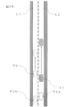
- FIG. 2 is a front view showing a part of the input device 17 of the present embodiment, and shows an example including a group of button switches arranged on spokes of a handle or the like.
- the illustrated input device 17 is a button switch used when setting ON / OFF or the like of the autonomous traveling control function (autonomous speed control function and autonomous steering control function) included in the control device 19.
- the input device 17 includes a main switch 171, a resume acceleration switch 172, a set coast switch 173, a cancel switch 174, an inter-vehicle distance adjustment switch 175, and a lane change support switch 176.
- the main switch 171 is a switch that turns on / off the power supply of the system that realizes the autonomous speed control function and the autonomous steering control function of the control device 19.
- the resume / accelerate switch 172 turns off the operation of the autonomous speed control function, then restarts the autonomous speed control function at the set speed before the OFF, increases the set speed, stops following the preceding vehicle, and then restarts. It is a switch that makes you do it.
- the set coast switch 173 is a switch that starts the autonomous speed control function at the traveling speed or lowers the set speed.
- the cancel switch 174 is a switch that turns off the autonomous speed control function.
- the inter-vehicle distance adjustment switch 175 is a switch for setting the inter-vehicle distance from the preceding vehicle, and is a switch for selecting one from a plurality of stages of settings such as short distance, medium distance, and long distance.
- the lane change support switch 176 is a switch for instructing (accepting) the start of the lane change when the control device 19 confirms with the driver that the lane change has started. By operating the lane change support switch 176 for a longer time than a predetermined time after approving the start of the lane change, the approval of the lane change proposal by the control device 19 can be revoked.
- a direction indicator lever of a direction indicator and a switch of another in-vehicle device 14 can be used as an input device 17.
- the control device 19 proposes whether or not to automatically change lanes
- the direction indicator lever is operated in the direction in which the direction indicator lever is operated instead of the proposed lane change. Change lanes.
- the input device 17 outputs the input setting information to the control device 19.
- the drive control device 18 controls the running of the own vehicle. For example, when the own vehicle travels at a constant speed by the autonomous speed control function, the drive control device 18 accelerates and decelerates so that the own vehicle reaches the set speed, and maintains the traveling speed. Controls the operation of the drive mechanism and the braking operation. Further, the drive control device 18 similarly controls the operation of the drive mechanism and the brake even when the own vehicle follows the preceding vehicle by the autonomous speed control function.
- the operation control of the drive mechanism includes the operation of the internal combustion engine in the case of an engine vehicle and the operation of a traveling motor in the case of an electric vehicle system. Further, in the case of a hybrid vehicle, the torque distribution between the internal combustion engine and the traveling motor is included.
- the drive control device 18 executes steering control of the own vehicle by controlling the operation of the steering actuator in addition to the operation control of the drive mechanism and the brake described above by the autonomous steering control function. For example, when the drive control device 18 executes lane keeping control by the autonomous steering control function, the drive control device 18 detects a lane marker in the own lane in which the own vehicle travels, and causes the own vehicle to travel in a predetermined position in the own lane. Controls the traveling position of the own vehicle in the width direction. Further, when the drive control device 18 executes the lane change support function, the overtaking support function, or the route traveling support function described later by the autonomous steering control function, the width direction of the own vehicle is such that the own vehicle changes lanes. Controls the traveling position in.
- the drive control device 18 executes the right / left turn support function by the autonomous steering control function, the drive control device 18 performs traveling control for turning right or left at an intersection or the like.
- the drive control device 18 controls the traveling of the own vehicle according to the instruction of the control device 19 described later. Further, as a traveling control method by the drive control device 18, other known methods can also be used.
- the control device 19 includes a ROM (Read Only Memory) that stores a program for controlling the running of the own vehicle, a CPU (Central Processing Unit) that executes the program stored in the ROM, and an accessible storage device. It is equipped with a functioning RAM (Random Access Memory) and the like.
- ROM Read Only Memory
- CPU Central Processing Unit
- RAM Random Access Memory
- the operating circuit instead of or together with the CPU (Central Processing Unit), MPU (Micro Processing Unit), DSP (Digital Signal Processor), ASIC (Application Specific Integrated Circuit), FPGA (Field Programmable Gate Array), etc. Can be used.
- the control device 19 has a running information acquisition function for acquiring information on the running state of the own vehicle by executing a program stored in the ROM by the CPU, a running scene determination function for determining the running scene of the own vehicle, and a self. It realizes an autonomous driving control function that autonomously controls the traveling speed and / or steering of the vehicle.
- the driving information acquisition function of the control device 19 is a function of acquiring driving information regarding the traveling state of the own vehicle.
- the control device 19 acquires the image information of the outside of the vehicle captured by the front camera, the rear camera, and the side camera of the sensor 11 as the traveling information by the traveling information acquisition function.
- the control device 19 acquires the detection results of the front radar, the rear radar, and the side radar as driving information by the traveling information acquisition function.
- the control device 19 also acquires the vehicle speed information of the own vehicle detected by the vehicle speed sensor of the sensor 11 and the image information of the driver's face captured by the in-vehicle camera as the traveling information by the traveling information acquisition function.
- control device 19 acquires the current position information of the own vehicle from the own vehicle position detection device 12 as the running information by the traveling information acquisition function.
- control device 19 acquires the set destination and the route to the destination from the navigation device 15 as travel information by the travel information acquisition function.
- the control device 19 uses a travel information acquisition function to provide travel information such as a curved road and the size of the curve (for example, curvature or radius of curvature), a confluence point, a branch point, a toll booth, and a position where the number of lanes is reduced. Is obtained from the map database 13.
- the control device 19 acquires the operation information of the in-vehicle device 14 by the driver as the traveling information from the in-vehicle device 14 by the traveling information acquisition function.
- the traveling scene determination function of the control device 19 is a function of determining a traveling scene in which the own vehicle is traveling by referring to the table stored in the ROM of the control device 19.
- a driving scene suitable for changing lanes or overtaking and a determination condition thereof are stored for each driving scene.
- the control device 19 refers to the table stored in the ROM by the traveling scene determination function, and determines whether or not the traveling scene of the own vehicle is a traveling scene suitable for, for example, changing lanes or overtaking.
- the control device 19 uses the traveling scene determination function, for example, the detection result by the front camera or the front radar included in the sensor 11, the vehicle speed of the own vehicle detected by the vehicle speed sensor, and the own vehicle position detection device 12 by the own vehicle position detection device 12. It is determined whether or not the own vehicle satisfies the above conditions based on the position information of the vehicle, and if the above conditions are satisfied, it is determined that the own vehicle is a "catch-up scene with the preceding vehicle".
- the autonomous travel control function of the control device 19 is a function that autonomously controls the travel of the own vehicle without depending on the operation of the driver.
- the autonomous travel control function of the control device 19 includes an autonomous speed control function that autonomously controls the traveling speed of the own vehicle and an autonomous steering control function that autonomously controls the steering of the own vehicle.
- an autonomous speed control function that autonomously controls the traveling speed of the own vehicle
- an autonomous steering control function that autonomously controls the steering of the own vehicle.
- the autonomous speed control function is a function that follows the preceding vehicle while performing inter-vehicle distance control so as to maintain the inter-vehicle distance according to the vehicle speed by setting the vehicle speed set by the driver as the upper limit. ..
- the autonomous speed control function performs constant speed traveling at the vehicle speed set by the driver.
- the former is also called inter-vehicle distance control, and the latter is also called constant speed control.
- the autonomous speed control function detects the speed limit of the traveling road from the road sign by the sensor 11, or acquires the speed limit from the map information of the map database 13, and automatically sets the speed limit to the set vehicle speed. It may include a function to do.
- the driver To activate the autonomous speed control function, the driver first operates the resume acceleration switch 172 or the set coast switch 173 of the input device 17 shown in FIG. 2 to input a desired traveling speed. For example, if the own vehicle is traveling at 70 km / h and the set coast switch 173 is pressed, the current traveling speed is set as it is, but if the speed desired by the driver is 80 km / h, resume acceleration is achieved. The set speed may be increased by pressing the switch 172 multiple times. On the contrary, assuming that the speed desired by the driver is 60 km / h, the set coast switch 173 may be pressed a plurality of times to lower the set speed.
- inter-vehicle distance desired by the driver may be selected by operating the inter-vehicle adjustment switch 175 of the input device 17 shown in FIG. 2, for example, from a plurality of stages of settings such as short distance, medium distance, and long distance.
- the constant speed control is executed when it is detected by the front radar of the sensor 11 or the like that there is no preceding vehicle in front of the own lane.
- the drive control device 18 controls the operation of the drive mechanism such as the engine and the brake while feeding back the vehicle speed data by the vehicle speed sensor so as to maintain the set running speed.
- Inter-vehicle distance control is executed when it is detected by the front radar of the sensor 11 or the like that a preceding vehicle exists in front of the own lane.
- the drive control device 18 feeds back the inter-vehicle distance data detected by the front radar so as to maintain the set inter-vehicle distance with the set traveling speed as the upper limit, and the drive mechanism such as the engine and the brake is used. Control the operation of. If the preceding vehicle stops while traveling under the inter-vehicle distance control, the own vehicle also stops following the preceding vehicle. Further, if the preceding vehicle starts within 30 seconds after the own vehicle has stopped, the own vehicle also starts and the following running by inter-vehicle distance control is started again.
- the autonomous speed control function of the present embodiment is a function of controlling the traveling speed of the own vehicle up to the first vehicle speed, which is the vehicle speed set by the driver, except when a predetermined condition is satisfied.
- the first vehicle speed which is the vehicle speed set by the driver
- the autonomous speed control function first determines whether or not the predetermined running motion is completed at the first vehicle speed. To do. Then, when it is determined that the predetermined traveling operation is completed at the first vehicle speed, the first vehicle speed is maintained.
- the second vehicle speed higher than the first vehicle speed set by the driver is temporarily set, and the second vehicle speed is set as the upper limit vehicle speed.
- temporarily setting the second vehicle speed means that after changing the vehicle speed setting of the own vehicle from the first vehicle speed to the second vehicle speed, the set vehicle speed is not maintained at the second vehicle speed, but is predetermined. It means that the speed is returned from the second vehicle speed to the first vehicle speed when the above conditions are satisfied. For example, the set vehicle speed is returned from the second vehicle speed to the first vehicle speed after the predetermined traveling operation of the own vehicle is completed.
- the predetermined traveling operation performed here is various traveling operations including at least one of lane change, overtaking, or change of traveling direction.
- the predetermined traveling operation includes at least the fact that the own vehicle overtakes the preceding vehicle by using the overtaking support function when the preceding vehicle is detected in front of the own vehicle.
- the predetermined driving operation is to at least change the lane of the own vehicle to the adjacent lane by using the route driving support function when the own lane in which the own vehicle travels merges with the adjacent lane adjacent to the own lane.
- the predetermined traveling operation includes at least changing the traveling direction of the own vehicle toward the branch road by using the route traveling support function when there is a branch road in the right lane.
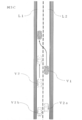
- FIGS. 3A to 3 show an example of control of the traveling operation according to the present embodiment.
- the traveling scene shown in FIG. 3A is when there is a preceding vehicle V2 traveling at a traveling speed slower than the first vehicle speed, which is the set speed of the own vehicle V1, in front of the own vehicle V1 traveling in the left traveling lane L1. , It is assumed that the own vehicle V1 overtakes the preceding vehicle V2.
- the own vehicle V1 when the own vehicle V1 catches up with the preceding vehicle V2 as shown in FIG. 3A, the own vehicle V1 can first overtake the preceding vehicle V2 within a predetermined time by the autonomous speed control function. Determine if. The traveling speed of the preceding vehicle V2 is detected by a sensor 11 (for example, a front camera and a front radar). The control device 19 determines whether or not the own vehicle V1 can overtake the preceding vehicle V2 within a predetermined time based on the first vehicle speed detected by the sensor 11 and the traveling speed of the preceding vehicle V2.
- the predetermined time is, for example, a general time (for example, 15 to 20 seconds) required for overtaking the preceding vehicle V2 determined by experience or experiment.
- the predetermined time may be the time until the traveling speed of the own vehicle V1 is limited when the traveling speed is restricted in front of the own vehicle V1 due to a curved road or the like, or the predetermined time may be the time until the traveling speed of the own vehicle V1 is restricted.
- the predetermined time may be the time until the own vehicle V1 reaches the merging point.
- the own vehicle V1 can overtake the preceding vehicle V2 within the general time required for overtaking.
- the control device 19 determines that the traveling operation is completed within a predetermined time by the autonomous speed control function. According to this judgment, as shown in FIG. 3A, the own vehicle V1 changes lanes from the left traveling lane L1 to the right overtaking lane L2 while maintaining the first vehicle speed set by the driver, and changes the right overtaking lane L2 to the first. Drive at one vehicle speed. This lane change is performed by using the overtaking support function of the autonomous steering control function described later.
- the own vehicle V1 After changing lanes, the own vehicle V1 travels in the overtaking lane L2 on the right side as shown in FIG. 3B. Since the difference between the first vehicle speed and the traveling speed of the preceding vehicle V2 is large, the own vehicle V1 traveling in the overtaking lane L2 on the right side is the preceding vehicle traveling in the left traveling lane L1 without increasing the vehicle speed of the own vehicle V1. It can overtake V2 in a short time. Then, after overtaking the preceding vehicle V2, as shown in FIG. 3C, the own vehicle V1 changes lanes from the right overtaking lane L2 to the left traveling lane L1 and enters in front of the preceding vehicle V2. In this way, the overtaking operation of the own vehicle V1 is completed.
- the control device 19 determines that the traveling operation is not completed within the predetermined time by the autonomous speed control function. ..
- the control device 19 of the present embodiment uses the autonomous speed control function to move from the first vehicle speed set by the driver. Change the vehicle speed of the own vehicle V1 to the second vehicle speed, which is also high.
- the method of setting the second vehicle speed is not particularly limited, but for example, within the general time required for overtaking based on the traveling speed of the preceding vehicle V2 detected by the sensor 11 and the general time required for overtaking. The vehicle speed at which overtaking is completed can be calculated back and this can be used as the second vehicle speed.
- the vehicle speed obtained by adding a predetermined vehicle speed (for example, 5 km / h to 10 km / h) to the first vehicle speed may be used as the second vehicle speed, or a predetermined ratio (for example,) to the first vehicle speed.
- the vehicle speed obtained by increasing the vehicle speed (5% to 10%) may be used as the second vehicle speed.
- the control device 19 of the present embodiment may automatically change the setting of the traveling speed of the own vehicle V1 from the first vehicle speed to the second vehicle speed by the autonomous speed control function without intervening the operation of the driver. .. Alternatively, the control device 19 may obtain the driver's consent before changing the vehicle speed of the own vehicle V1 by the autonomous speed control function.
- the request for consent to the driver can be made by notifying the driver with a presentation device 16 such as a display provided in the navigation device 15. Then, the driver operates the lane change support switch 176 of the input device 17 and inputs a response of consent, permission, or refusal to the control device 19.
- the control device 19 of the present embodiment accelerates the own vehicle V1 in order to increase the vehicle speed of the own vehicle V1 from the first vehicle speed to the second vehicle speed, and here, accelerates from the first vehicle speed to the second vehicle speed.
- the acceleration at that time may be an acceleration larger than the acceleration when accelerating from a vehicle speed lower than the first vehicle speed to the first vehicle speed (hereinafter, referred to as "first acceleration”) (hereinafter, referred to as "second acceleration"). This is to reduce the time required for overtaking.
- the first acceleration is set within the range of acceleration that is considered to be comfortable to ride, which is obtained from experience or experiment.
- the method of setting the second acceleration is not particularly limited, but for example, an acceleration that completes the acceleration within the general time required for changing lanes (for example, 4 to 8 seconds) is calculated and used as the second acceleration. be able to.
- the acceleration obtained by adding a predetermined acceleration for example, 0.5 m / s 2 to 5.0 m / s 2
- the second acceleration may be an acceleration obtained by increasing the acceleration by a predetermined ratio (for example, 5% to 10%).
- control device 19 of the present embodiment completes the acceleration from the first vehicle speed to the second vehicle speed during the lane change by the autonomous speed control function, but the acceleration may be completed before the start of the lane change. .. This is to prevent the driver from missing the opportunity to change lanes in the overtaking driving operation.
- the own vehicle V1 changes lanes as shown in FIG. 3A while accelerating from the first vehicle speed set by the driver to the second vehicle speed. This lane change is performed by using the overtaking support function of the autonomous steering control function described later. After changing lanes, the own vehicle V1 travels in the overtaking lane L2 on the right side as shown in FIG. 3B. Due to the difference between the second vehicle speed and the traveling speed of the preceding vehicle V2, the own vehicle V1 traveling in the overtaking lane L2 on the right side can overtake the preceding vehicle V2 traveling in the traveling lane L1 on the left side. Then, after overtaking the preceding vehicle V2, as shown in FIG.
- the own vehicle V1 changes lanes from the right overtaking lane L2 to the left traveling lane L1 and enters in front of the preceding vehicle V2. In this way, the overtaking operation of the own vehicle V1 is completed. After the overtaking operation is completed, the traveling speed of the own vehicle V1 is returned from the second vehicle speed to the first vehicle speed.
- the second vehicle speed is set to another.
- the vehicle speed may be set to be higher than the vehicle speed of the vehicle V2a. This is to secure a sufficient distance between the vehicle and the other vehicle V2a.
- the traveling operation in which the own vehicle V1 overtakes the preceding vehicle V2 when the own vehicle V1 detects the following vehicle V2b traveling behind the own vehicle V1 while traveling in the left traveling lane L1, the second vehicle speed is set. , The vehicle speed may be set to be higher than the vehicle speed of the following vehicle V2b.
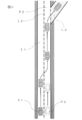
- FIG. 4 shows another example of control of the running motion according to the present embodiment.
- the traveling scene shown in FIG. 4 when the traveling lane L1 on the left side on which the own vehicle V1 travels merges with the overtaking lane L2 on the right side in front of the own vehicle V1, another vehicle V3 exists in the overtaking lane L2 on the right side. It is intended for such a situation.
- the own vehicle V1 needs to change lanes from the traveling lane L1 on the left side to the overtaking lane L2 on the adjacent right side. This lane change operation needs to be completed by the time the own vehicle V1 reaches the confluence point P1 between the traveling lane L1 on the left side and the adjacent overtaking lane L2 on the right side.
- the control device 19 of the present embodiment uses the autonomous speed control function based on the traveling speed of the other vehicle V3 traveling in the overtaking lane L2 on the right side and the remaining distance from the current position of the own vehicle V1 to the merging point P1. It is determined whether or not the lane change of the own vehicle V1 is completed within a predetermined time.
- the predetermined time of this traveling scene is, for example, the time required for the own vehicle V1 to reach the merging point P1 from the current position.
- the traveling speed of the other vehicle V3 traveling in the overtaking lane L2 on the right side is detected by a sensor 11 (for example, a side camera and a side radar).
- the control device 19 determines that the traveling operation is completed within a predetermined time by the autonomous speed control function. According to this determination, as shown in FIG. 4, the own vehicle V1 changes lanes so as to enter in front of the other vehicle V3 while maintaining the first vehicle speed set by the driver. This lane change is performed by using the lane change support function or the route driving support function described later. In this way, by the confluence point P1, the own vehicle V1 completes the lane change to the overtaking lane L2 on the right side.
- the control device 19 determines that the traveling operation is not completed within the predetermined time by the autonomous speed control function.
- the control device 19 of the present embodiment has the first vehicle speed set by the driver by the autonomous speed control function.
- the vehicle speed of the own vehicle V1 is changed to a higher second vehicle speed.
- the method of setting the second vehicle speed is not particularly limited, but is based on, for example, the traveling speed of the other vehicle V3 traveling in the overtaking lane L2 on the right side and the remaining distance from the current position of the own vehicle V1 to the merging point P1.
- the second vehicle speed is set so that the lane change of the own vehicle V1 is completed within a predetermined time.
- the control device 19 of the present embodiment may automatically change the setting of the traveling speed of the own vehicle V1 from the first vehicle speed to the second vehicle speed by the autonomous speed control function without intervening the operation of the driver. ..
- the control device 19 of the present embodiment may obtain the driver's consent before changing the vehicle speed of the own vehicle V1 by the autonomous speed control function.
- the request for consent to the driver can be made by notifying the driver with a presentation device 16 such as a display provided in the navigation device 15. Then, the driver operates the lane change support switch 176 of the input device 17 and inputs a response of consent, permission, or refusal to the control device 19.
- the own vehicle V1 can be the other vehicle V3 as shown in FIG. Can be overtaken and the lane change to the overtaking lane L2 on the right side can be completed by the confluence point P1.
- This lane change can be performed by using the lane change support function or the route driving support function described later. After the lane change operation is completed, the traveling speed of the own vehicle V1 is returned from the second vehicle speed to the first vehicle speed.
- the control device 19 of the present embodiment accelerates the own vehicle V1 in order to increase the vehicle speed of the own vehicle V1 from the first vehicle speed to the second vehicle speed, and here, when accelerating from the first vehicle speed to the second vehicle speed.
- the acceleration of may be a second acceleration larger than the first acceleration. This is to shorten the time required for overtaking.
- the first acceleration is set within the range of acceleration that is considered to be comfortable to ride, which is obtained from experience or experiment.
- the method of setting the second acceleration is not particularly limited, but for example, an acceleration that completes the acceleration within the general time required for changing lanes can be calculated and used as the second acceleration.
- the acceleration obtained by adding a predetermined acceleration (for example, 0.5 m / s 2 to 5.0 m / s 2 ) to the first acceleration may be used as the second acceleration, or with respect to the first acceleration.
- the second acceleration may be an acceleration obtained by increasing the acceleration by a predetermined ratio (for example, 5% to 10%).
- the control device 19 of the present embodiment completes the acceleration from the first vehicle speed to the second vehicle speed during the lane change by the autonomous speed control function, but the acceleration may be completed before the start of the lane change. .. This is to prevent the driver from missing the opportunity to change lanes in the overtaking driving operation.
- FIG. 5 shows yet another example of control of a series of traveling operations according to the present embodiment.
- the own vehicle V1 traveling in the left traveling lane L1 makes a traveling direction toward the branch road L3 on the right overtaking lane L2 side.
- branch roads such as exits of motorways exist on the left side of the driving lane L1
- branch roads such as exits on the right side of the overtaking lane L2. It may exist.
- the own vehicle V1 In order to change the traveling direction toward the branch road L3, the own vehicle V1 needs to change the lane from the traveling lane L1 on the left side to the adjacent overtaking lane L2 on the right side, and further change the traveling direction toward the branch road L3. There is. This series of traveling operations needs to be completed by the time the own vehicle V1 reaches the branch point P2 of the branch road L3. Even in such a case, the control device 19 of the present embodiment has an opportunity to change lanes when controlling the traveling motion of the own vehicle V1 as in the case of controlling the traveling motion as shown in FIGS. 3A to 4. Suppress the loss of.
- the control device 19 of the present embodiment uses the autonomous speed control function based on the traveling speed of the other vehicle V3 traveling in the overtaking lane L2 on the right side and the remaining distance from the current position of the own vehicle V1 to the branch point P2. It is determined whether or not the change of the traveling direction is completed within a predetermined time.
- the predetermined time of this traveling scene is, for example, the time required for the own vehicle V1 to reach the branch point P2 from the current position.
- the traveling speed of the other vehicle V3 traveling in the overtaking lane L2 on the right side is detected by a sensor 11 (for example, a side camera and a side radar).
- the control device 19 determines that the series of traveling operations is completed within a predetermined time by the autonomous speed control function. According to this determination, as shown in FIG. 5, the own vehicle V1 changes lanes so as to enter in front of the other vehicle V3 while maintaining the first vehicle speed set by the driver. Then, by the time the own vehicle V1 reaches the branch point P2, the traveling direction of the own vehicle V1 is changed toward the branch road L3. This lane change and travel direction change are performed by using the lane change support function and the route travel support function, which will be described later. In this way, by the branch point P2, the own vehicle V1 completes the change of the traveling direction toward the branch road L3.
- the control device 19 determines that the traveling operation is not completed within the predetermined time by the autonomous speed control function.
- the control device 19 of the present embodiment is set by the driver by the autonomous speed control function.
- the vehicle speed of the own vehicle V1 is changed to the second vehicle speed higher than the one vehicle speed.
- the method of setting the second vehicle speed is not particularly limited, but is determined based on, for example, the traveling speed of another vehicle V3 traveling in the overtaking lane L2 on the right side and the remaining distance from the current position of the own vehicle V1 to the branch point P2. Set the second vehicle speed so that the change of the traveling direction of the own vehicle V1 is completed within the time.
- the control device 19 of the present embodiment may automatically change the setting of the traveling speed of the own vehicle V1 from the first vehicle speed to the second vehicle speed by the autonomous speed control function without intervening the operation of the driver. ..
- the control device 19 of the present embodiment may obtain the driver's consent before changing the vehicle speed of the own vehicle V1 by the autonomous speed control function.
- the request for consent to the driver can be made by notifying the driver with a presentation device 16 such as a display provided in the navigation device 15. Then, the driver operates the lane change support switch 176 of the input device 17 and inputs a response of consent, permission, or refusal to the control device 19.
- the own vehicle V1 is the other vehicle V3.
- the branch point P2 the lane change to the right overtaking lane L2 and the change of the traveling direction toward the branch road L3 can be completed.
- This lane change and travel direction change can be performed by using the lane change support function and the route travel support function, which will be described later.
- the traveling speed of the own vehicle V1 is returned from the second vehicle speed to the first vehicle speed.
- the control device 19 of the present embodiment accelerates the own vehicle V1 in order to increase the vehicle speed of the own vehicle V1 from the first vehicle speed to the second vehicle speed, and here, when accelerating from the first vehicle speed to the second vehicle speed.
- the acceleration of may be a second acceleration larger than the first acceleration. This is to reduce the time required for overtaking.
- the first acceleration is set within the range of acceleration that is considered to be comfortable to ride, which is obtained from experience or experiment.
- the method of setting the second acceleration is not particularly limited, but for example, an acceleration that completes the acceleration within the general time required for changing lanes can be calculated and used as the second acceleration.
- the acceleration obtained by adding a predetermined acceleration (for example, 0.5 m / s 2 to 5.0 m / s 2 ) to the first acceleration may be used as the second acceleration, or with respect to the first acceleration.
- the second acceleration may be an acceleration obtained by increasing the acceleration by a predetermined ratio (for example, 5% to 10%).
- the control device 19 of the present embodiment completes the acceleration from the first vehicle speed to the second vehicle speed during the lane change by the autonomous speed control function, but the acceleration may be completed before the start of the lane change. .. This is to prevent the driver from missing the opportunity to change lanes in the overtaking driving operation.
- the control device 19 of the present embodiment is, for example, when the first vehicle speed set by the driver is smaller than a predetermined value or more than the speed limit of the road on which the own vehicle travels.
- the second vehicle speed may be set.
- the control device 19 sets the vehicle speed of the own vehicle to the second vehicle speed.
- the method for setting the second vehicle speed is not particularly limited, but for example, the difference between the first vehicle speed and the speed limit can be set to be a predetermined value (for example, 5 km / h to 10 km / h) or less.
- the autonomous steering control function is a function that executes steering control of the own vehicle by controlling the operation of the steering actuator when a predetermined condition is satisfied during the execution of the above-mentioned automatic speed control function.
- This autonomous steering control function includes, for example, a lane keeping function, a lane change support function, an overtaking support function, a route traveling support function, and the like.
- the lane keeping function is a function that assists the driver in steering operation by controlling the steering actuator so as to travel near the center of the lane, for example.
- the lane keeping function is also called a lane width direction maintaining function.
- the lane change support function turns on the turn signal when the driver operates the direction indicator lever, and when the preset lane change start condition is satisfied, the lane change support function is a series of processes for changing the lane.
- a certain lane change operation (hereinafter referred to as "LCP") is started.
- the lane change support function determines whether or not the lane change start condition is satisfied based on various driving information acquired by the driving information acquisition function.
- the conditions for starting the lane change are not particularly limited, but the lane keep mode of the hands-on mode, the hands-on judgment is being made, the vehicle is traveling at a speed of 60 km / h or more, the lane is in the lane change direction, and the lane is changed.
- the lane keep mode of the hands-on mode will be described in detail later, but is a state in which the autonomous speed control function and the lane keep function of the autonomous steering control function are being executed and the holding of the steering wheel by the driver is detected.
- “hands-on determination in progress” means a state in which the driver continues to hold the steering wheel.
- the lane change support function starts LCP when the lane change start condition is met.
- This LCP includes lateral movement of the own vehicle to the adjacent lane and lane change maneuvering (hereinafter, referred to as “LCM”) that actually moves to the adjacent lane.
- LCM lane change maneuvering
- the lane change support function presents information indicating that the lane is being changed automatically to the driver by the presenting device 16 to call attention to the surroundings.
- the lane change support function turns off the turn signal and starts executing the lane keeping function in the adjacent lane.
- the overtaking support function presents overtaking information when a preceding vehicle slower than the own vehicle exists in front of the own lane and satisfies a predetermined overtaking proposal condition set in advance.
- the overtaking information is information for proposing to the driver to overtake the preceding vehicle.
- the driver operates the lane change support switch 176 of the input device 17 to consent to the presentation of the overtaking information (corresponding to the consent input), and satisfies the preset overtaking start condition.
- the LCP described above is started.
- the overtaking support function determines whether or not the overtaking proposal condition and the overtaking start condition are satisfied based on various driving information acquired by the driving information acquisition function.
- the conditions for overtaking proposals are not particularly limited, but are in the hands-off mode lane keep mode, driving at a speed of 60 km / h or more, having a lane in the lane change direction, and 5 seconds in the lane change destination lane.
- the type of lane marker can be changed
- the radius of curvature of the road is 250 m or more
- the speed of your vehicle is 5 km / h or more slower than the set speed
- the preceding vehicle The speed is 10 km / or more slower than the set speed
- the distance between the own vehicle and the preceding vehicle is less than the preset threshold based on the speed difference between the own vehicle and the preceding vehicle, and the lane change destination. It can be exemplified that all the conditions such as the speed of the preceding vehicle existing in the lane satisfying a predetermined condition are satisfied.
- the lane keep mode of the hands-off mode will be described in detail later, but is a mode in which the autonomous speed control function and the lane keep function of the autonomous steering control function are being executed and the driver does not need to hold the steering wheel.
- the condition that the speed of the preceding vehicle existing in the lane of the lane change destination satisfies a predetermined condition is applied differently depending on the type of the lane of the lane change destination. For example, on a multi-lane road with left-hand traffic, when changing lanes from the left lane to the right lane, the speed of the preceding vehicle in the left lane is about 5 km / km higher than the speed of the preceding vehicle in the right lane. The condition is that it is faster than h.
- the speed difference between the own vehicle and the preceding vehicle in the left lane is within about 5 km / h. Is a condition.
- the conditions regarding the relative speed difference between the own vehicle and the preceding vehicle are reversed on the right-hand traffic road.
- the overtaking support function turns on the turn signal and starts LCP when the driver consents to the presentation of overtaking information and satisfies the predetermined overtaking start condition set in advance.
- the conditions for starting overtaking are not particularly limited, but the lane keep mode of the hands-on mode, the hands-on judgment is being made, the vehicle is traveling at a speed of 60 km / h or more, there is a lane in the lane change direction, and the lane is changed.
- the condition that the speed of the preceding vehicle is 10 km / h or more slower than the set speed can be changed by the driver's setting, and the set speed after the change becomes the overtaking start condition.
- the speed that can be changed for example, 15 km / h and 20 km / h can be selected in addition to 10 km / h.
- the condition that the speed of the preceding vehicle existing in the lane to which the lane is changed satisfies the predetermined condition is the same as the above-mentioned overtaking proposal condition.
- the overtaking support function starts LCP when the overtaking start condition is satisfied, and executes lateral movement to the adjacent lane and LCM.
- the overtaking support function presents information indicating that the lane is automatically changed to the driver by the presenting device 16 while executing the LCP, and calls attention to the surroundings.
- the overtaking support function turns off the turn signal and starts executing the lane keeping function in the adjacent lane.
- the overtaking support function proposes to the driver by the presenting device 16 that the driver returns to the original lane as shown in FIG. 8 when the overtaking proposal condition is satisfied again after overtaking the preceding vehicle. If the driver accepts this proposal by operating the lane change support switch 176 of the input device 17 and satisfies the overtaking start condition, the overtaking support function returns the own vehicle to the original lane. Start LCP.
- the route travel support function has a branch point, a confluence point, an exit, a toll booth, and other travel direction change points on the set route, the distance to the travel direction change point is within a predetermined distance, and the predetermined route.
- the route travel information is presented by the presenting device 16 to propose a lane change to the travel direction change point.
- the route traveling support function starts LCP when the lane change proposal is accepted by the operation of the lane change support switch 176 and the predetermined route traveling start condition is satisfied.
- the route travel support function determines whether or not the route travel proposal condition and the route travel start condition are satisfied based on various travel information acquired by the travel information acquisition function.
- the normal navigation device 15 guides the route.
- the navigation function is executed.
- the route driving support function is from the right lane to the center lane when the route driving support function is within the first predetermined distance to the branch point (for example, about 2.5 km to 1.0 km before the branch point) and the route driving proposal conditions are satisfied. Propose a lane change to the route based on route driving information.
- the first predetermined distance (also referred to as a lane change proposal section) is preset according to the number of lane changes required to move to the lane in which the traveling direction change point exists. For example, as shown in FIG. 9, when it is necessary to change lanes twice from the right lane to the left lane via the center lane, as illustrated, the distance to the branch point is about 2.5 km to 1.0 km before.
- the section becomes the first predetermined distance (lane change proposal section).
- the route driving proposal conditions are not particularly limited, but the destination is set by the navigation device 15, the lane keep mode is in the hands-off mode, the vehicle is traveling at a speed of 60 km / h or more, and the lane is reached. It can be exemplified that all the conditions such as that there is a lane in the changing direction, that the type of lane marker can be changed, and that the radius of curvature of the road is 250 m or more are satisfied. In the route driving proposal condition, even if there is no space where the lane can be changed at the lane change destination, the route driving information is presented in order to notify the driver that the lane change along the route is necessary.
- the route driving support function turns on the turn signal and starts LCP when the driver consents to the lane change to go to the branch point and the route driving start condition is satisfied.
- the conditions for starting route driving are not particularly limited, but the lane keep mode of the hands-on mode, the hands-on judgment is being made, the vehicle is traveling at a speed of 60 km / h or more, there is a lane in the lane change direction, and the lane. There is a space where you can change lanes in the destination lane, the type of lane marker can be changed, you are driving in the lane change proposal section, and the radius of curvature of the road is 250 m or more. It can be exemplified that all the conditions are satisfied.
- the route driving support function starts LCP when the route driving start condition is satisfied, and executes lateral movement to the central lane and LCM.
- the route driving support function turns off the turn signal and starts executing the lane keeping function in the central lane.
- the route driving support function presents information indicating that the lane is automatically changed to the driver by the presenting device 16 while executing the LCP, and calls attention to the surroundings.
- the route driving support function is within a second predetermined distance to the branch point (for example, about 2.3 km to 700 m before the branch point) while the lane keep function is being executed in the central lane. If there is, and the route traveling start condition is satisfied, the direction indicator is turned on to start the second LCP, and the lane is changed from the center lane to the left lane. When the second LCM is completed, the route driving support function turns off the turn signal and starts executing the lane keeping function in the left lane.
- the route driving support function is within a third predetermined distance to the branch point (for example, about 800 m to 150 m before the branch point) while executing the lane keeping function in the left lane, and the route driving start condition is set. When it is satisfied, the turn signal is turned on. In addition, the route driving support function starts autonomous steering control from a point beyond the branch point to the branch road, and changes lanes from the left lane to the branch road. When the lane change to the branch road is completed, the route driving support function turns off the turn signal and starts executing the lane keeping function on the branch road.
- FIG. 10 is a block diagram showing a state transition of each function established in the control device 19.
- the system shown in the figure means an autonomous traveling control system realized by the control device 19.
- the main switch 171 of FIG. 2 When the main switch 171 of FIG. 2 is turned on from the system OFF state shown in the figure, the system is put into the standby state. From this standby state, the autonomous speed control is activated by turning on the set coast switch 173 or the resume acceleration switch 172 of FIG.
- the above-mentioned constant speed control or inter-vehicle distance control is started, and the driver can drive his / her own vehicle simply by operating the steering wheel without stepping on the accelerator or the brake.
- the mode transitions to the lane keep mode of the autonomous steering control / hands-on mode.
- the condition (1) is not particularly limited, but the lane markers on both sides of the own vehicle are detected, the driver has the steering wheel, the vehicle is traveling near the center of the lane, and the winker is activated. All conditions such as not being, the wiper not operating at high speed (HI), and if there is a high-precision map, there are no toll booths, exits, confluences, intersections, or lane reduction points within about 200 m ahead. Can be illustrated.
- the hands-on mode refers to a mode in which the autonomous steering control does not operate unless the driver holds the steering wheel
- the hands-off mode refers to a mode in which the autonomous steering control operates even if the driver releases his / her hand from the steering wheel.
- condition (2) in FIG. 10 If the condition (2) in FIG. 10 is satisfied while the lane keep mode of the autonomous steering control / hands-on mode is being executed, the mode transitions to the lane keep mode of the autonomous steering control / hands-off mode.
- the condition (2) is not particularly limited, but the vehicle is traveling on a motorway, is traveling on a road structurally separated from the oncoming lane, and is traveling on a road having a high-precision map. You must be driving, you are driving at a vehicle speed below the speed limit, the GPS signal is valid, the driver has a handle, the driver is facing forward, and the tollgate is within about 800 m ahead.
- condition (3) of FIG. 10 is satisfied while the lane keep mode of the autonomous steering control / hands-off mode is being executed, the mode shifts to the lane keep mode of the autonomous steering control / hands-on mode.
- the condition (3) is not particularly limited, but the vehicle is traveling on a road other than a motorway, is traveling on a two-way traffic section, and is traveling on a road without a high-precision map.
- condition (4) of FIG. 10 is satisfied while the lane keep mode of the autonomous steering control / hands-off mode is being executed, the autonomous steering control is stopped and the process shifts to the autonomous speed control.
- the condition (4) is not particularly limited, but one of the following is that the lane markers on both sides of the own vehicle are not detected for a certain period of time, the driver operates the steering wheel, and the wiper operates at high speed (HI). It can be exemplified that the condition is satisfied. Further, if the condition (5) of FIG. 10 is satisfied while the lane keep mode of the autonomous steering control / hands-off mode is being executed, the autonomous steering control and the autonomous speed control are stopped and the state shifts to the standby state.
- the condition (5) is not particularly limited, but the driver operates the brake, the driver operates the cancel switch 174 in FIG. 2, the door of the own vehicle is opened, and the seat belt of the driver's seat is released. That, the seating sensor detected that the driver was no longer in the driver's seat, the select lever was other than "D” or "M”, the parking brake was activated, and the vehicle's electronic stability control was turned off. , The electronic stability control has been activated, the snow mode has been turned on, the emergency brake has been activated, the vehicle has stopped due to vehicle speed control, and the vehicle has been stopped for about 3 minutes. However, it detected poor visibility such as dirt, backlight, rain / fog, etc.
- the front radar detected shielding, radio interference, the front radar detected misalignment, and the side radar It can be exemplified that any of the conditions such as shielding, detection of radio wave interference, and detection of axis deviation by the side radar is satisfied.
- condition (6) of FIG. 10 is satisfied while the autonomous steering control / hands-on mode is being executed, the autonomous steering control is stopped and the process shifts to the autonomous speed control.
- the condition (6) is not particularly limited, but the lane markers on both sides of the own vehicle are no longer detected, the driver operates the steering wheel, the driver operates the blinker, and the wiper operates at high speed (HI). Either that, if there is a high-precision map, it became a tollhouse section, or that the front camera detected poor visibility that could not correctly recognize the object due to dirt, backlight, rain, fog, etc. You can exemplify what to do. Further, if the condition (7) of FIG.
- the condition (7) is not particularly limited, but the driver operates the brake, the driver operates the cancel switch 174 in FIG. 2, the door of the own vehicle is opened, and the seat belt of the driver's seat is released. That, the seating sensor detected that the driver had left the driver's seat, the select lever was other than "D" or "M”, the parking brake was activated, and the vehicle's electronic stability control was turned off. , The electronic stability control was activated, the snow mode was turned on, the emergency brake was activated, the vehicle stopped due to vehicle speed control, and then the stopped state continued for about 3 minutes, front radar. It can be exemplified that any of the conditions such as shielding, detection of radio wave interference, and detection of axis deviation by the front radar is satisfied.
- the condition (8) in FIG. 10 is satisfied while the autonomous speed control is being executed, the state transitions to the standby state.
- the condition (8) is not particularly limited, but the driver operates the brake, the driver operates the cancel switch 174 in FIG. 2, the door of the own vehicle is opened, and the seat belt of the driver's seat is released. That, the seating sensor detected that the driver had left the driver's seat, the select lever was other than "D” or "M”, the parking brake was activated, and the vehicle's electronic stability control was turned off. , The electronic stability control was activated, the snow mode was turned on, the emergency brake was activated, the vehicle stopped due to vehicle speed control, and then the stopped state continued for about 3 minutes, front radar. It can be exemplified that any of the conditions such as shielding, detection of radio wave interference, and detection of axis deviation by the front radar is satisfied.
- condition (9) in FIG. 10 If the condition (9) in FIG. 10 is satisfied while the lane keep mode of the autonomous steering control / hands-off mode is being executed, the mode transitions to the lane change mode of the autonomous steering control / hands-on mode.
- the condition (8) is not particularly limited, but is one of the conditions that the driver presses the lane change support switch 176 in FIG. 2 when the system proposes a lane change, and that the driver operates the blinker. Can be illustrated.
- condition (10) of FIG. 10 is satisfied while the lane change mode of the autonomous steering control / hands-on mode is being executed, the mode transitions to the lane keep mode of the autonomous steering control / hands-on mode.
- This condition (10) is not particularly limited, but the speed limit was exceeded before the start of the LCP, the driver held the steering wheel and stepped on the accelerator pedal before the start of the LCP, and there was a slow car ahead. After pressing the lane change support switch 176 during the lane change proposal, the LCP could not be started within 10 seconds, and after pressing the lane change support switch 176 during the lane change proposal to drive according to the route.
- the LCP could not be started and the vehicle was too close to the branch, the actual LCM could not be started within 5 seconds after the LCP was activated, the LCP was started, and the vehicle speed was about 50 km / h before the LCM was started.
- the LCP was activated, there was no space in the adjacent lane required to change lanes before starting the LCM, the driver canceled before the start of the LCM, and the lane marker was not before the start of the LCM. It was detected, before the start of LCM, it was judged that there was no adjacent lane in the direction to change lanes, or there was no adjacent lane within a certain distance ahead, and before the start of LCM, the radius of curvature within a certain distance ahead.
- the driver did not have a handle within about 2 seconds after pressing the lane change support switch 176 during the lane change proposal when there was a slow car ahead, during the lane change proposal to drive according to the route After pressing the lane change support switch 176, it is established under one of the conditions that the driver did not hold the handle within about 2 seconds), the driver turned off the winker, the LCP was completed, etc. It can be exemplified that the condition is satisfied.
- the main switch 171 is turned off in any of the autonomous steering control / hands-off mode, the autonomous steering control / hands-on mode, the autonomous speed control, and the standby state, the system is turned off.
- FIGS. 11A to 12B are flowcharts showing the traveling control process according to the present embodiment.
- 11A to 11B show the basic processing of the traveling control process according to the present embodiment
- FIGS. 12A to 12B show the subroutine of step S10 of FIG. 11A.
- steps S1 of FIG. 11A will be described in order.
- the travel control process described below is executed by the control device 19 at predetermined time intervals.
- the autonomous driving control function of the control device 19 executes autonomous speed control and autonomous steering control, and the width direction of the own vehicle so that the own vehicle travels in the lane at a speed set by the driver. It will be described that the lane keep control for controlling the traveling position in the above is performed.
- step S1 of FIG. 11A the control device 19 determines whether or not the main switch 171 is ON. When the main switch 171 is OFF, the control device 19 repeats step S1 until the main switch 171 is turned ON. On the other hand, when the main switch 171 is ON, the process proceeds to step S2.
- step S2 the control device 19 determines whether or not the driver has set the traveling speed.
- the traveling speed set by the driver in step S2 is the first vehicle speed. If the traveling speed is not set, the process returns to step S1, and the control device 19 repeats steps S1 and S2 until the traveling speed is set. On the other hand, if the traveling speed is set, the process proceeds to step S3.
- the traveling speed is set by the driver by operating the resume acceleration switch 172 or the set coast switch 173 of the input device 17 shown in FIG. 2 to input a desired traveling speed.
- step S3 the control device 19 detects whether or not there is a preceding vehicle in front of the lane in which the own vehicle travels by using the forward radar (sensor 11) that detects an obstacle in front of the own vehicle.
- the process proceeds to step S4, and the control device 19 executes the inter-vehicle distance control.
- step S5 the control device 19 executes constant speed control.
- the driver can drive the vehicle at a desired speed simply by operating the steering wheel without stepping on the accelerator or the brake.
- step S6 the condition (1) for the control device 19 to transition to the lane keep mode of the autonomous steering control / hands-on mode described above is satisfied. Determine whether or not to do so. If the condition (1) is satisfied, the process proceeds to step S7, and if the condition (1) is not satisfied, the process returns to step S1.
- step S7 the control device 19 detects whether or not there is a preceding vehicle in front of the lane in which the own vehicle is traveling by using the front radar (sensor 11) that detects an obstacle in front of the own vehicle.
- the control device 19 proceeds to step S8 to execute the inter-vehicle distance control / lane keep mode.
- step S9 executes the constant speed control / lane keep mode. In this state, the execution processing of the lane change support function, the overtaking support function, or the route traveling support function in step S10 is performed. The details of step S10 will be described later.
- step S11 of FIG. 11B the control device 19 sets the automatic steering control / hands-off mode described above. It is determined whether or not the condition (2) for transitioning to is satisfied. If the condition (2) is satisfied, the process proceeds to step S12, and if the condition (2) is not satisfied, the process proceeds to step S15.
- step S12 in which the condition (2) for transitioning to the automatic steering control / hands-off mode is satisfied, the control device 19 uses the forward radar (sensor 11) that detects an obstacle in front of the own vehicle, and the own vehicle travels. Detects whether or not there is a preceding vehicle in front of the lane. When detecting the preceding vehicle, the control device 19 proceeds to step S13 to execute inter-vehicle distance control, lane keep mode, and hands-off. On the other hand, when the preceding vehicle is not detected, the control device 19 proceeds to step S14 to execute constant speed control, lane keep mode, and hands-off.
- step S15 the control device 19 detects whether or not there is a preceding vehicle in front of the lane in which the own vehicle is traveling by using the front radar (sensor 11) that detects an obstacle in front of the own vehicle.
- the control device 19 proceeds to step S16.
- step S16 similarly to step S6, the control device 19 determines whether or not the condition (1) for transitioning to the lane keep mode of the autonomous steering control / hands-on mode is satisfied, and when the condition (1) is satisfied. Proceeds to step S17.
- step S17 similarly to step S11, the control device 19 determines whether or not the condition (2) for transitioning to the automatic steering control / hands-off mode is satisfied, and if the condition (2) is satisfied, the step. Return to S12 and continue the subsequent processing.
- the process returns to step S1 and the control device 19 continues the subsequent processing.
- FIGS. 12A to 12B The driving control processing of the lane change support function, the route driving support function, and the overtaking support function in step S10 is shown in FIGS. 12A to 12B.
- FIG. 12A is a flowchart showing the steps before the start of the lane change operation (LCP)
- FIG. 12B is a flowchart showing the steps from the start to the end of the lane change operation.
- steps S21 of FIG. 12A will be described in order.
- step S21 of FIG. 12A the control device 19 determines whether or not the control start condition by any of the lane change support function, the overtaking support function, and the route driving support function is satisfied.
- the control device 19 includes the traveling speed of the own vehicle / other vehicle obtained from the sensor 11, the distance between the own vehicle and the other vehicle, the position information of the own vehicle obtained from the own vehicle position detection device 12, and the map database 13. This judgment is made based on the map information obtained from. If none of the control start conditions by these functions are satisfied, the process proceeds to step S11 in FIG. 11B without performing a traveling operation such as changing lanes. On the other hand, if the control start condition by any of the functions is satisfied, the process proceeds to step S22.
- step S22 the control device 19 determines whether or not the function satisfying the control start condition is the overtaking support function. If the function satisfying the start condition is the overtaking support function, the process proceeds to step S29 described later. On the other hand, if the function satisfying the start condition is the lane change support function or the route driving support function, the process proceeds to step S23.
- step S23 before changing lanes by the lane change support function or the route driving support function, whether there is another vehicle in the lane to be changed by using the sensor 11 (front camera, rear camera, and side radar). Judge whether or not. If no other vehicle is detected in the lane to be changed in step S23, the process proceeds to step S43 in FIG. 12B, and the lane change operation is started while maintaining the first vehicle speed set by the driver. On the other hand, if another vehicle is detected in the lane to which the lane is changed in step S23, the process proceeds to step S24.
- step S24 the control device 19 determines whether or not the traveling operation for changing lanes is completed within a predetermined time even while maintaining the first vehicle speed set by the driver.
- the control device 19 is obtained from the traveling speed of the own vehicle and the other vehicle obtained from the sensor 11, the distance between the own vehicle and the other vehicle, the position information of the own vehicle obtained from the own vehicle position detection device 12, and the map database 13. Make a judgment based on the map information. If it is determined that the driving operation for changing lanes is completed within a predetermined time even while maintaining the first vehicle speed set by the driver, the process proceeds to step S43 in FIG. 12B, and the lane is maintained while maintaining the first vehicle speed set by the driver. Start the change operation. On the other hand, if it is determined that the driving operation for changing lanes is not completed within the predetermined time while maintaining the first vehicle speed set by the driver, the process proceeds to step S25.
- step S25 the control device 19 determines the second vehicle speed with respect to the current first vehicle speed set by the driver, and when the set vehicle speed is set to the second vehicle speed, the traveling operation of changing lanes is completed within a predetermined time. Determine if. If it is determined that the traveling operation for changing lanes is not completed within the predetermined time even at the second vehicle speed, the process proceeds to step S11 in FIG. 11B without performing the traveling operation such as changing lanes. On the other hand, if it is determined that the traveling operation for changing lanes is completed within a predetermined time at the second vehicle speed, the process proceeds to step S26.
- step S26 the control device 19 detects the speed limit of the traveling lane in which the own vehicle is traveling by the traveling information acquisition function, and compares the speed limit with the second vehicle speed. If the second vehicle speed is higher than the speed limit, the process proceeds to step S11 in FIG. 11B without controlling the lane change and performing a traveling operation such as changing the lane. On the other hand, if the second vehicle speed is lower than the speed limit, the process proceeds to step S27.
- step S27 the control device 19 asks the driver for consent to change the setting of the traveling speed of the own vehicle from the first vehicle speed to the second vehicle speed. If the driver refuses to change the vehicle speed, the process proceeds to step S11 in FIG. 11B without performing a running operation such as changing lanes. On the other hand, if the driver approves the change in the vehicle speed, the process proceeds to step S28, and the traveling speed of the own vehicle is set to the second vehicle speed. Then, the process proceeds to step S31 of FIG. 12B, and the control device 19 starts the lane change operation.
- step S22 if the function satisfying the start condition is the overtaking support function, the process proceeds to step S29.
- the control device 19 starts running control by the overtaking support function when there is a preceding vehicle traveling at a vehicle speed slower than the vehicle speed of the own vehicle in front of the own vehicle. Therefore, the traveling scene in step S29 is a scene in which a preceding vehicle traveling at a vehicle speed slower than the first vehicle speed exists in front of the own vehicle traveling at the first vehicle speed set by the driver.
- step S29 the control device 19 determines whether or not a series of running operations overtaking the preceding vehicle is completed within a predetermined time while maintaining the first vehicle speed set by the driver.
- the control device 19 makes a determination based on the traveling speeds of the own vehicle and the preceding vehicle obtained from the sensor 11, the position information of the own vehicle obtained from the own vehicle position detection device 12, and the map information obtained from the map database 13. .. If it is determined that a series of running operations will be completed within a predetermined time while maintaining the first vehicle speed set by the driver, the process proceeds to step S43 in FIG. 12B, and the lane change operation is performed while maintaining the first vehicle speed set by the driver. To start. On the other hand, if it is determined that the series of traveling operations is not completed within the predetermined time while maintaining the first vehicle speed set by the driver, the process proceeds to step S30.
- step S30 the control device 19 determines the second vehicle speed with respect to the current first vehicle speed set by the driver, and when the set vehicle speed is set to the second vehicle speed, a series of running operations overtaking the preceding vehicle within a predetermined time. Determine if is complete. If it is determined that the series of traveling operations is not completed within the predetermined time even at the second vehicle speed, the process proceeds to step S11 in FIG. 11B without performing driving operations such as changing lanes. On the other hand, if it is determined that the series of traveling operations is completed within the predetermined time at the second vehicle speed, the process proceeds to step S26. When the process proceeds to step S26, the processes of steps S26 to S28 are as described above.
- step S31 on the left side of FIG. 12B the traveling speed of the own vehicle is set to the second vehicle speed.
- step S43 on the right side of FIG. 12B the traveling speed of the own vehicle is still set to the first vehicle speed.
- step S31 the routine of the lane change operation in which the traveling speed of the own vehicle is set to the second vehicle speed, starting from step S31, will be described.
- step S31 the control device 19 starts the lane change operation and proceeds to step S32.
- step S32 the control device 19 instructs the drive control device 18 to start accelerating from the first vehicle speed in order to increase the traveling speed of the own vehicle to the set second vehicle speed, and proceeds to step S33.
- step S33 the control device 19 executes steering control, starts the lateral movement of the own vehicle and the subsequent traveling operation of changing lanes, and proceeds to step S34.
- step S34 the control device 19 instructs the drive control device 18 to complete the acceleration when the traveling speed of the own vehicle reaches the second vehicle speed during the lane change.
- step S33 and step S34 the order of step S33 and step S34 is switched. Then, the process proceeds from step S34 to step S35, and in step S35, the control device 19 completes the traveling operation of changing lanes. After the traveling operation for changing lanes is completed in step S35, the process proceeds to step S36.
- step S36 the control device 19 determines whether or not the lane change operation currently being performed is due to the overtaking support function. If the lane change operation does not depend on the overtaking support function, that is, the lane change support function or the route travel support function, the process proceeds to step S41, and the traveling speed setting of the own vehicle is returned from the second vehicle speed to the first vehicle speed. On the other hand, if it is a lane change operation by the overtaking support function, the process proceeds to step S37.
- step S37 the control device 19 instructs the drive control device 18 to drive the own vehicle at a constant speed at the second vehicle speed in the overtaking lane, and proceeds to step S38.
- step S38 the control device 19 determines whether or not the own vehicle traveling at a constant speed at the second vehicle speed has overtaken the preceding vehicle.
- the control device 19 detects the preceding vehicle with the sensor 11 (rear camera and side radar) and determines whether or not the overtaking is completed. If it is determined that the overtaking of the preceding vehicle has not been completed, the process returns to step S37, and the own vehicle continues to run at a constant speed at the second vehicle speed. On the other hand, if it is determined that the overtaking of the preceding vehicle is completed, the process proceeds to step S39.
- step S39 the control device 19 instructs the drive control device 18 to perform steering control.
- the driving operation of lateral movement and subsequent lane change is started so that the own vehicle enters in front of the preceding vehicle.
- step S40 the control device 19 completes the traveling operation of changing lanes, and proceeds to step S41.
- step S41 the control device 19 returns the setting of the traveling speed of the own vehicle from the second vehicle speed to the first vehicle speed, and proceeds to step S42.
- step S42 the control device 19 ends the lane change operation, and proceeds to step 11 of FIG. 11B.
- step S43 the control device 19 starts the lane change operation while maintaining the first vehicle speed set by the driver, and proceeds to step S44.
- step S44 the control device 19 starts the traveling operation of lateral movement and subsequent lane change, and proceeds to step S45.
- step S45 the control device 19 completes the traveling operation of changing lanes.
- step S46 it is determined whether or not the lane change operation currently being performed is due to the overtaking support function. If the lane change operation does not depend on the overtaking support function, that is, the lane change support function or the route traveling support function, the process proceeds to step S42 and the lane change operation ends. On the other hand, if it is a lane change operation by the overtaking support function, the process proceeds to step S47.
- step S47 the control device 19 instructs the drive control device 18 to drive the own vehicle at a constant speed at the first vehicle speed in the overtaking lane, and proceeds to step S48.
- step S48 the control device 19 determines whether or not the own vehicle traveling at a constant speed at the first vehicle speed has overtaken the preceding vehicle.
- the control device 19 detects the preceding vehicle with the sensor 11 (rear camera and side radar) and determines whether or not the overtaking is completed. If it is determined that the overtaking of the preceding vehicle has not been completed, the process returns to step S47, and the own vehicle continues to run at a constant speed at the first vehicle speed. On the other hand, if it is determined that the overtaking of the preceding vehicle is completed, the process proceeds to step S49.
- step S49 the control device 19 instructs the drive control device 18 to perform steering control.
- the driving operation of lateral movement and subsequent lane change is started so that the own vehicle enters in front of the preceding vehicle.
- step S50 the control device 19 completes the traveling operation of changing lanes, and proceeds to step S42.
- step S42 the control device 19 ends the lane change operation and proceeds to step 11 of FIG. 11B.
- the vehicle travel control device 1 and the travel control method according to the present embodiment when controlling the travel operation of the own vehicle, which is at least one of lane change, overtaking, and change in travel direction.
- the traveling operation of the own vehicle accompanied by the lane change is controlled by setting the second vehicle speed higher than the vehicle speed set by the driver. In some cases, it is possible to prevent the vehicle from missing the opportunity to change lanes.
- the driver is set by returning the vehicle speed of the own vehicle from the second vehicle speed to the first vehicle speed after the predetermined driving operation is completed. It is possible to shorten the time for traveling at a vehicle speed exceeding the speed.
- the vehicle travel control device 1 and the travel control method according to the present embodiment when accelerating from the first vehicle speed to the second vehicle speed, when accelerating from a vehicle speed lower than the first vehicle speed to the first vehicle speed.
- a second acceleration that is larger than the set first acceleration it is possible to complete the acceleration of the own vehicle in a short time, suppress the hindrance of other vehicles from traveling, and perform driving operations including lane changes. You can go smoothly.
- the acceleration from the first vehicle speed to the second vehicle speed is controlled so as to be performed before the start of the lane change or during the lane change. , It is possible to smoothly perform driving operations including lane change.
- the vehicle travel control device 1 and the travel control method according to the present embodiment it is presented to the driver that the traveling speed of the own vehicle is changed from the first vehicle speed to the second vehicle speed before being set to the second vehicle speed. By doing so, it is possible to suppress a change in the traveling speed against the driver's will.
- the vehicle speed of the own vehicle is set to the second vehicle speed, so that the surrounding other vehicles can be detected.
- the distance between the vehicle and the vehicle can be secured.
- the vehicle travel control device 1 and the travel control method according to the present embodiment another vehicle traveling behind the own lane in which the own vehicle is traveling, or another vehicle traveling behind the adjacent lane adjacent to the own lane, etc.
- the vehicle speed of the own vehicle By setting the vehicle speed of the own vehicle to the second vehicle speed when the vehicle is detected, it is possible to secure the inter-vehicle distance from the other vehicle approaching from the rear of the own vehicle before and after the lane change.
- the own vehicle overtakes the preceding vehicle by overtaking the preceding vehicle traveling in front of the own vehicle in the own lane in which the own vehicle travels. In some cases, it is possible to prevent the vehicle from missing the opportunity to change lanes.
- the second vehicle speed is set to be equal to or higher than the vehicle speed of the other vehicle.
- the second vehicle speed is set to the following vehicle.
- the vehicle speed By setting the vehicle speed to be higher than the vehicle speed, it is possible to alert the following vehicle to change lanes first, and even if the following vehicle also starts the overtaking operation during the overtaking operation of the own vehicle, the own vehicle is behind. It is possible to secure the inter-vehicle distance with the following vehicle approaching from.
- the road ahead on which the own vehicle travels merges from the own lane in which the own vehicle travels to the adjacent lane adjacent to the own lane to lane. If the number decreases, or if the distance from the current position of the own vehicle to the confluence of the own lane and the adjacent lane is less than or equal to the predetermined distance, the second vehicle speed can be set to drive to the confluence. The operation can be completed.
- the vehicle travel control device 1 and the travel control method according to the present embodiment when the first vehicle speed is smaller than the speed limit of the road on which the own vehicle travels by a predetermined value or more, the vehicle speed of the own vehicle is set to the second vehicle speed. By setting to, the distance between the vehicle and other vehicles can be secured.
- the vehicle travel control device 1 and the travel control method according to the present embodiment when the own vehicle changes lanes from the traveling lane to the overtaking lane, the vehicle speed is set to the second vehicle speed to overtake. It is possible to secure the inter-vehicle distance from other vehicles traveling in the lane.
- the vehicle speed is set to the second vehicle speed.
- the vehicle speed is set to the second vehicle speed.
- Driving control device 11 Sensor 12 ... Vehicle position detection device 13 ... Map database 14 ... In-vehicle device 15 ... Navigation device 16 ... Presentation device 17 ... Input device 171 ... Main switch 172 ... Resume / accelerate switch 173 ... Set / Coast switch 174 ... Cancel switch 175 ... Inter-vehicle adjustment switch 176 ... Lane change support switch 18 ... Drive control device 19 ... Control device V1 ... Own vehicle V2 ... Leading vehicle V2a ... Other vehicle V2b ... Following vehicle V3 ... Other vehicle L1 ... Driving lane L2 ... Overtaking lane L3 ... Branch road P1 ... Confluence point P2 ... Branch point
Landscapes
- Engineering & Computer Science (AREA)
- Automation & Control Theory (AREA)
- Transportation (AREA)
- Mechanical Engineering (AREA)
- Human Computer Interaction (AREA)
- Traffic Control Systems (AREA)
- Control Of Driving Devices And Active Controlling Of Vehicle (AREA)
Abstract
L'invention concerne un procédé de commande de déplacement concernant des véhicules qui permet d'effectuer une régulation autonome de la vitesse de déplacement de son propre véhicule (V1) de manière à maintenir une première vitesse du véhicule définie par un conducteur et d'effectuer une commande autonome de changement de voie de son propre véhicule (V1) lorsqu'une condition prédéterminée est satisfaite, le procédé de commande de déplacement déterminant, lors de la commande de l'opération de déplacement prédéterminée de son propre véhicule (V1) correspondant à au moins un changement de voie, un dépassement, et un changement de direction de déplacement, si l'opération de déplacement prédéterminée sera achevée à la première vitesse du véhicule, et lors de la détermination selon laquelle l'opération de déplacement prédéterminée sera achevée à la première vitesse du véhicule, règle la vitesse de son propre véhicule (V1) à la première vitesse pour commander l'opération de déplacement prédéterminée, tandis que, lors de la détermination que l'opération de déplacement prédéterminée ne sera pas achevée à la première vitesse du véhicule, règle la vitesse de son propre véhicule (V1) à une seconde vitesse supérieure à la première vitesse pour commander l'opération de déplacement prédéterminée ; et un dispositif de commande de déplacement (1).
Priority Applications (2)
| Application Number | Priority Date | Filing Date | Title |
|---|---|---|---|
| JP2021561070A JPWO2021106146A1 (fr) | 2019-11-28 | 2019-11-28 | |
| PCT/JP2019/046584 WO2021106146A1 (fr) | 2019-11-28 | 2019-11-28 | Procédé de commande de déplacement et dispositif de commande de déplacement pour véhicule |
Applications Claiming Priority (1)
| Application Number | Priority Date | Filing Date | Title |
|---|---|---|---|
| PCT/JP2019/046584 WO2021106146A1 (fr) | 2019-11-28 | 2019-11-28 | Procédé de commande de déplacement et dispositif de commande de déplacement pour véhicule |
Publications (1)
| Publication Number | Publication Date |
|---|---|
| WO2021106146A1 true WO2021106146A1 (fr) | 2021-06-03 |
Family
ID=76128883
Family Applications (1)
| Application Number | Title | Priority Date | Filing Date |
|---|---|---|---|
| PCT/JP2019/046584 WO2021106146A1 (fr) | 2019-11-28 | 2019-11-28 | Procédé de commande de déplacement et dispositif de commande de déplacement pour véhicule |
Country Status (2)
| Country | Link |
|---|---|
| JP (1) | JPWO2021106146A1 (fr) |
| WO (1) | WO2021106146A1 (fr) |
Citations (6)
| Publication number | Priority date | Publication date | Assignee | Title |
|---|---|---|---|---|
| JP2014000900A (ja) * | 2012-06-19 | 2014-01-09 | Toyota Motor Corp | 車両制御装置 |
| JP2016009201A (ja) * | 2014-06-20 | 2016-01-18 | 富士重工業株式会社 | 車両の運転支援装置 |
| JP2016088504A (ja) * | 2014-10-31 | 2016-05-23 | 株式会社デンソー | 運転支援装置 |
| JP2016215917A (ja) * | 2015-05-22 | 2016-12-22 | トヨタ自動車株式会社 | 車速制限装置及び車速制御装置 |
| WO2018123344A1 (fr) * | 2016-12-27 | 2018-07-05 | 本田技研工業株式会社 | Dispositif de commande de véhicule, procédé de commande de véhicule, et programme |
| JP2019014383A (ja) * | 2017-07-07 | 2019-01-31 | いすゞ自動車株式会社 | 車速制御装置及び車速制御方法 |
-
2019
- 2019-11-28 WO PCT/JP2019/046584 patent/WO2021106146A1/fr active Application Filing
- 2019-11-28 JP JP2021561070A patent/JPWO2021106146A1/ja active Pending
Patent Citations (6)
| Publication number | Priority date | Publication date | Assignee | Title |
|---|---|---|---|---|
| JP2014000900A (ja) * | 2012-06-19 | 2014-01-09 | Toyota Motor Corp | 車両制御装置 |
| JP2016009201A (ja) * | 2014-06-20 | 2016-01-18 | 富士重工業株式会社 | 車両の運転支援装置 |
| JP2016088504A (ja) * | 2014-10-31 | 2016-05-23 | 株式会社デンソー | 運転支援装置 |
| JP2016215917A (ja) * | 2015-05-22 | 2016-12-22 | トヨタ自動車株式会社 | 車速制限装置及び車速制御装置 |
| WO2018123344A1 (fr) * | 2016-12-27 | 2018-07-05 | 本田技研工業株式会社 | Dispositif de commande de véhicule, procédé de commande de véhicule, et programme |
| JP2019014383A (ja) * | 2017-07-07 | 2019-01-31 | いすゞ自動車株式会社 | 車速制御装置及び車速制御方法 |
Also Published As
| Publication number | Publication date |
|---|---|
| JPWO2021106146A1 (fr) | 2021-06-03 |
Similar Documents
| Publication | Publication Date | Title |
|---|---|---|
| JP7143946B2 (ja) | 車両の走行制御方法及び走行制御装置 | |
| JP7140277B2 (ja) | 車両の走行制御方法及び走行制御装置 | |
| WO2020230551A1 (fr) | Procédé et dispositif de commande de déplacement de véhicule | |
| JP7164030B2 (ja) | 車両の走行制御方法及び走行制御装置 | |
| JP7434866B2 (ja) | 車両の走行制御方法および走行制御装置 | |
| JP7156517B2 (ja) | 車両の走行制御方法及び走行制御装置 | |
| JP7331450B2 (ja) | 車両の走行制御方法及び走行制御装置 | |
| JP7156516B2 (ja) | 車両の走行制御方法及び走行制御装置 | |
| JP7287498B2 (ja) | 運転制御方法及び運転制御装置 | |
| WO2021106159A1 (fr) | Procédé de commande de conduite et dispositif de commande de conduite | |
| WO2021106146A1 (fr) | Procédé de commande de déplacement et dispositif de commande de déplacement pour véhicule | |
| WO2022107277A1 (fr) | Procédé de commande de déplacement de véhicule et dispositif de commande de déplacement | |
| RU2792474C1 (ru) | Способ управления вождением и устройство управления вождением | |
| WO2023089837A1 (fr) | Procédé d'aide au déplacement et dispositif d'aide au déplacement pour véhicule | |
| WO2023089835A1 (fr) | Procédé et dispositif d'aide au déplacement d'un véhicule | |
| EP4309969A1 (fr) | Procédé de commande de déplacement et dispositif de commande de déplacement pour un véhicule | |
| RU2780639C1 (ru) | Способ управления движением и устройство управления движением для транспортного средства | |
| JP2022072222A (ja) | 車両の走行制御方法及び走行制御装置 | |
| JP2022072209A (ja) | 車両の走行制御方法及び走行制御装置 | |
| JP2023069806A (ja) | 車両の走行制御方法及び走行制御装置 | |
| JP2022079948A (ja) | 車両の走行制御方法及び走行制御装置 |
Legal Events
| Date | Code | Title | Description |
|---|---|---|---|
| 121 | Ep: the epo has been informed by wipo that ep was designated in this application |
Ref document number: 19954161 Country of ref document: EP Kind code of ref document: A1 |
|
| ENP | Entry into the national phase |
Ref document number: 2021561070 Country of ref document: JP Kind code of ref document: A |
|
| NENP | Non-entry into the national phase |
Ref country code: DE |
|
| 122 | Ep: pct application non-entry in european phase |
Ref document number: 19954161 Country of ref document: EP Kind code of ref document: A1 |