WO2020230551A1 - 車両の走行制御方法及び走行制御装置 - Google Patents
車両の走行制御方法及び走行制御装置 Download PDFInfo
- Publication number
- WO2020230551A1 WO2020230551A1 PCT/JP2020/017234 JP2020017234W WO2020230551A1 WO 2020230551 A1 WO2020230551 A1 WO 2020230551A1 JP 2020017234 W JP2020017234 W JP 2020017234W WO 2020230551 A1 WO2020230551 A1 WO 2020230551A1
- Authority
- WO
- WIPO (PCT)
- Prior art keywords
- vehicle
- control
- autonomous
- target point
- lane
- Prior art date
Links
- 238000000034 method Methods 0.000 title claims description 37
- 238000003860 storage Methods 0.000 claims abstract description 10
- 230000008859 change Effects 0.000 description 74
- 230000006870 function Effects 0.000 description 62
- 230000008569 process Effects 0.000 description 22
- 230000006399 behavior Effects 0.000 description 13
- 238000001514 detection method Methods 0.000 description 13
- 230000007704 transition Effects 0.000 description 8
- 230000001133 acceleration Effects 0.000 description 7
- 238000012790 confirmation Methods 0.000 description 7
- 238000010586 diagram Methods 0.000 description 7
- 230000004397 blinking Effects 0.000 description 6
- 238000012545 processing Methods 0.000 description 6
- 238000003825 pressing Methods 0.000 description 5
- 230000007246 mechanism Effects 0.000 description 4
- 230000009467 reduction Effects 0.000 description 3
- 238000002485 combustion reaction Methods 0.000 description 2
- 125000002066 L-histidyl group Chemical group [H]N1C([H])=NC(C([H])([H])[C@](C(=O)[*])([H])N([H])[H])=C1[H] 0.000 description 1
- 238000013459 approach Methods 0.000 description 1
- 230000000994 depressogenic effect Effects 0.000 description 1
- 238000009826 distribution Methods 0.000 description 1
- 239000000284 extract Substances 0.000 description 1
- 238000012423 maintenance Methods 0.000 description 1
- 238000002360 preparation method Methods 0.000 description 1
Images


Classifications
-
- B—PERFORMING OPERATIONS; TRANSPORTING
- B60—VEHICLES IN GENERAL
- B60W—CONJOINT CONTROL OF VEHICLE SUB-UNITS OF DIFFERENT TYPE OR DIFFERENT FUNCTION; CONTROL SYSTEMS SPECIALLY ADAPTED FOR HYBRID VEHICLES; ROAD VEHICLE DRIVE CONTROL SYSTEMS FOR PURPOSES NOT RELATED TO THE CONTROL OF A PARTICULAR SUB-UNIT
- B60W30/00—Purposes of road vehicle drive control systems not related to the control of a particular sub-unit, e.g. of systems using conjoint control of vehicle sub-units, or advanced driver assistance systems for ensuring comfort, stability and safety or drive control systems for propelling or retarding the vehicle
- B60W30/14—Adaptive cruise control
- B60W30/143—Speed control
-
- B—PERFORMING OPERATIONS; TRANSPORTING
- B62—LAND VEHICLES FOR TRAVELLING OTHERWISE THAN ON RAILS
- B62D—MOTOR VEHICLES; TRAILERS
- B62D15/00—Steering not otherwise provided for
- B62D15/02—Steering position indicators ; Steering position determination; Steering aids
- B62D15/025—Active steering aids, e.g. helping the driver by actively influencing the steering system after environment evaluation
-
- B—PERFORMING OPERATIONS; TRANSPORTING
- B60—VEHICLES IN GENERAL
- B60W—CONJOINT CONTROL OF VEHICLE SUB-UNITS OF DIFFERENT TYPE OR DIFFERENT FUNCTION; CONTROL SYSTEMS SPECIALLY ADAPTED FOR HYBRID VEHICLES; ROAD VEHICLE DRIVE CONTROL SYSTEMS FOR PURPOSES NOT RELATED TO THE CONTROL OF A PARTICULAR SUB-UNIT
- B60W30/00—Purposes of road vehicle drive control systems not related to the control of a particular sub-unit, e.g. of systems using conjoint control of vehicle sub-units, or advanced driver assistance systems for ensuring comfort, stability and safety or drive control systems for propelling or retarding the vehicle
- B60W30/10—Path keeping
- B60W30/12—Lane keeping
-
- B—PERFORMING OPERATIONS; TRANSPORTING
- B60—VEHICLES IN GENERAL
- B60W—CONJOINT CONTROL OF VEHICLE SUB-UNITS OF DIFFERENT TYPE OR DIFFERENT FUNCTION; CONTROL SYSTEMS SPECIALLY ADAPTED FOR HYBRID VEHICLES; ROAD VEHICLE DRIVE CONTROL SYSTEMS FOR PURPOSES NOT RELATED TO THE CONTROL OF A PARTICULAR SUB-UNIT
- B60W50/00—Details of control systems for road vehicle drive control not related to the control of a particular sub-unit, e.g. process diagnostic or vehicle driver interfaces
- B60W50/06—Improving the dynamic response of the control system, e.g. improving the speed of regulation or avoiding hunting or overshoot
-
- B—PERFORMING OPERATIONS; TRANSPORTING
- B60—VEHICLES IN GENERAL
- B60W—CONJOINT CONTROL OF VEHICLE SUB-UNITS OF DIFFERENT TYPE OR DIFFERENT FUNCTION; CONTROL SYSTEMS SPECIALLY ADAPTED FOR HYBRID VEHICLES; ROAD VEHICLE DRIVE CONTROL SYSTEMS FOR PURPOSES NOT RELATED TO THE CONTROL OF A PARTICULAR SUB-UNIT
- B60W50/00—Details of control systems for road vehicle drive control not related to the control of a particular sub-unit, e.g. process diagnostic or vehicle driver interfaces
- B60W50/08—Interaction between the driver and the control system
- B60W50/082—Selecting or switching between different modes of propelling
-
- B—PERFORMING OPERATIONS; TRANSPORTING
- B60—VEHICLES IN GENERAL
- B60W—CONJOINT CONTROL OF VEHICLE SUB-UNITS OF DIFFERENT TYPE OR DIFFERENT FUNCTION; CONTROL SYSTEMS SPECIALLY ADAPTED FOR HYBRID VEHICLES; ROAD VEHICLE DRIVE CONTROL SYSTEMS FOR PURPOSES NOT RELATED TO THE CONTROL OF A PARTICULAR SUB-UNIT
- B60W60/00—Drive control systems specially adapted for autonomous road vehicles
- B60W60/001—Planning or execution of driving tasks
-
- B—PERFORMING OPERATIONS; TRANSPORTING
- B62—LAND VEHICLES FOR TRAVELLING OTHERWISE THAN ON RAILS
- B62D—MOTOR VEHICLES; TRAILERS
- B62D15/00—Steering not otherwise provided for
- B62D15/02—Steering position indicators ; Steering position determination; Steering aids
- B62D15/025—Active steering aids, e.g. helping the driver by actively influencing the steering system after environment evaluation
- B62D15/0255—Automatic changing of lane, e.g. for passing another vehicle
-
- G—PHYSICS
- G06—COMPUTING; CALCULATING OR COUNTING
- G06V—IMAGE OR VIDEO RECOGNITION OR UNDERSTANDING
- G06V20/00—Scenes; Scene-specific elements
- G06V20/50—Context or environment of the image
- G06V20/56—Context or environment of the image exterior to a vehicle by using sensors mounted on the vehicle
-
- G—PHYSICS
- G08—SIGNALLING
- G08G—TRAFFIC CONTROL SYSTEMS
- G08G1/00—Traffic control systems for road vehicles
- G08G1/16—Anti-collision systems
- G08G1/167—Driving aids for lane monitoring, lane changing, e.g. blind spot detection
-
- B—PERFORMING OPERATIONS; TRANSPORTING
- B60—VEHICLES IN GENERAL
- B60W—CONJOINT CONTROL OF VEHICLE SUB-UNITS OF DIFFERENT TYPE OR DIFFERENT FUNCTION; CONTROL SYSTEMS SPECIALLY ADAPTED FOR HYBRID VEHICLES; ROAD VEHICLE DRIVE CONTROL SYSTEMS FOR PURPOSES NOT RELATED TO THE CONTROL OF A PARTICULAR SUB-UNIT
- B60W50/00—Details of control systems for road vehicle drive control not related to the control of a particular sub-unit, e.g. process diagnostic or vehicle driver interfaces
- B60W2050/0062—Adapting control system settings
- B60W2050/0075—Automatic parameter input, automatic initialising or calibrating means
- B60W2050/0095—Automatic control mode change
- B60W2050/0096—Control during transition between modes
-
- B—PERFORMING OPERATIONS; TRANSPORTING
- B60—VEHICLES IN GENERAL
- B60W—CONJOINT CONTROL OF VEHICLE SUB-UNITS OF DIFFERENT TYPE OR DIFFERENT FUNCTION; CONTROL SYSTEMS SPECIALLY ADAPTED FOR HYBRID VEHICLES; ROAD VEHICLE DRIVE CONTROL SYSTEMS FOR PURPOSES NOT RELATED TO THE CONTROL OF A PARTICULAR SUB-UNIT
- B60W2420/00—Indexing codes relating to the type of sensors based on the principle of their operation
- B60W2420/40—Photo or light sensitive means, e.g. infrared sensors
- B60W2420/403—Image sensing, e.g. optical camera
-
- B—PERFORMING OPERATIONS; TRANSPORTING
- B60—VEHICLES IN GENERAL
- B60W—CONJOINT CONTROL OF VEHICLE SUB-UNITS OF DIFFERENT TYPE OR DIFFERENT FUNCTION; CONTROL SYSTEMS SPECIALLY ADAPTED FOR HYBRID VEHICLES; ROAD VEHICLE DRIVE CONTROL SYSTEMS FOR PURPOSES NOT RELATED TO THE CONTROL OF A PARTICULAR SUB-UNIT
- B60W2552/00—Input parameters relating to infrastructure
- B60W2552/53—Road markings, e.g. lane marker or crosswalk
-
- B—PERFORMING OPERATIONS; TRANSPORTING
- B60—VEHICLES IN GENERAL
- B60W—CONJOINT CONTROL OF VEHICLE SUB-UNITS OF DIFFERENT TYPE OR DIFFERENT FUNCTION; CONTROL SYSTEMS SPECIALLY ADAPTED FOR HYBRID VEHICLES; ROAD VEHICLE DRIVE CONTROL SYSTEMS FOR PURPOSES NOT RELATED TO THE CONTROL OF A PARTICULAR SUB-UNIT
- B60W2556/00—Input parameters relating to data
- B60W2556/40—High definition maps
-
- B—PERFORMING OPERATIONS; TRANSPORTING
- B60—VEHICLES IN GENERAL
- B60W—CONJOINT CONTROL OF VEHICLE SUB-UNITS OF DIFFERENT TYPE OR DIFFERENT FUNCTION; CONTROL SYSTEMS SPECIALLY ADAPTED FOR HYBRID VEHICLES; ROAD VEHICLE DRIVE CONTROL SYSTEMS FOR PURPOSES NOT RELATED TO THE CONTROL OF A PARTICULAR SUB-UNIT
- B60W2710/00—Output or target parameters relating to a particular sub-units
- B60W2710/20—Steering systems
-
- B—PERFORMING OPERATIONS; TRANSPORTING
- B60—VEHICLES IN GENERAL
- B60W—CONJOINT CONTROL OF VEHICLE SUB-UNITS OF DIFFERENT TYPE OR DIFFERENT FUNCTION; CONTROL SYSTEMS SPECIALLY ADAPTED FOR HYBRID VEHICLES; ROAD VEHICLE DRIVE CONTROL SYSTEMS FOR PURPOSES NOT RELATED TO THE CONTROL OF A PARTICULAR SUB-UNIT
- B60W2720/00—Output or target parameters relating to overall vehicle dynamics
- B60W2720/10—Longitudinal speed
Definitions
- the present invention relates to a vehicle travel control method and a travel control device including autonomous driving control.
- This application claims priority based on Japanese Patent Application No. 2019-92431 of the Japanese patent application filed on May 15, 2019, and the above-mentioned designated countries are permitted to be incorporated by reference to the literature. Incorporate the content of the application into this application by reference and make it part of the description of this application.
- the map curvature stored in the traveling lane on the road map of the vehicle is read, and the map curvature is determined.
- the leading curvature based on the traveling locus of the preceding vehicle to be followed and the estimated lateral position deviation based on the vehicle speed of the own vehicle are obtained, and the estimated lateral position deviation is added to the lateral position of the own vehicle to drive the own vehicle along the traveling lane.
- An object to be solved by the present invention is to provide a vehicle travel control method and a travel control device capable of suppressing the behavior of the vehicle when switching the autonomous control of the vehicle.
- the map information of the storage medium is obtained from the autonomous control of the vehicle using the information recognized from the camera image before the vehicle enters the unrecognizable area.
- the above problem is solved by switching to the autonomous control of the vehicle using.
- the behavior of the vehicle can be suppressed when switching the autonomous control of the vehicle.
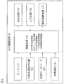
- FIG. 1 is a block diagram showing a configuration of a vehicle travel control device 1 according to the present embodiment.
- the vehicle travel control device 1 of the present embodiment is also an embodiment that implements the vehicle travel control method according to the present invention.
- the vehicle travel control device 1 according to the present embodiment includes a sensor 11, a vehicle position detection device 12, a map database 13, an in-vehicle device 14, a presentation device 15, and an input device 16.
- a drive control device 17 and a control device 18 are provided. These devices are connected by, for example, CAN (Controller Area Network) or other in-vehicle LAN in order to transmit and receive information to each other.
- CAN Controller Area Network
- the sensor 11 detects the running state of the own vehicle. For example, as the sensor 11, a front camera that images the front of the own vehicle, a rear camera that images the rear of the own vehicle, a front radar that detects an obstacle in front of the own vehicle, and a rear that detects an obstacle behind the own vehicle. Radar, side radar that detects obstacles on the left and right sides of the vehicle, vehicle speed sensor that detects the vehicle speed of the vehicle, touch sensor (capacity sensor) that detects whether the driver has a handle ) And an in-vehicle camera that captures the driver.
- the sensor 11 may be configured to use one of the plurality of sensors described above, or may be configured to use two or more types of sensors in combination.
- the detection result of the sensor 11 is output to the control device 18 at predetermined time intervals.
- the own vehicle position detection device 12 is composed of a GPS unit, a gyro sensor, a vehicle speed sensor, etc., detects radio waves transmitted from a plurality of satellite communications by the GPS unit, and periodically obtains position information of the target vehicle (own vehicle).
- the current position of the target vehicle is detected based on the acquired position information of the target vehicle, the angle change information acquired from the gyro sensor, and the vehicle speed acquired from the vehicle speed sensor.
- the position information of the target vehicle detected by the own vehicle position detection device 12 is output to the control device 18 at predetermined time intervals.
- the map database 13 is a memory that stores three-dimensional high-precision map information including location information of various facilities and specific points and is accessible from the control device 18.
- the three-dimensional high-precision map information stored in the map database 13 is three-dimensional map information based on the road shape detected when traveling on an actual road using a data acquisition vehicle, and is a curved road together with the map information. And detailed and highly accurate position information such as the size of the curve (for example, curvature or radius of curvature), road confluence, branch point, tollgate, lane reduction position, service area / parking area, etc.
- the map information associated with is the map information associated with.
- the in-vehicle device 14 is various devices mounted on the vehicle and operates by being operated by the driver. Such vehicle-mounted devices include steering, accelerator pedals, brake pedals, navigation devices, turn signals, wipers, lights, horns, and other specific switches. When the in-vehicle device 14 is operated by the driver, the information is output to the control device 18.
- the presentation device 15 for example, a display included in the navigation device, a display incorporated in the room mirror, a display incorporated in the meter unit, a head-up display projected on the windshield, a speaker included in the audio device, and a vibrating body are embedded. It is a device such as a windshield seat device.
- the presenting device 15 notifies the driver of the presented information and the lane change information, which will be described later, according to the control of the control device 18.
- the input device 16 is, for example, a device such as a button switch capable of inputting manually by the driver, a touch panel arranged on the display screen, or a microphone capable of inputting by the driver's voice.
- the driver can operate the input device 16 to input the setting information for the presentation information presented by the presentation device 15.
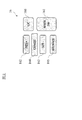
- FIG. 2 is a front view showing a part of the input device 16 of the present embodiment, and shows an example including a group of button switches arranged on the spokes of the steering wheel.
- the illustrated input device 16 is a button switch used when setting ON / OFF of the autonomous speed control function and the autonomous steering control function included in the control device 18, and includes a main switch 161 and a resume / accelerate switch 162. It includes a set coast switch 163, a cancel switch 164, an inter-vehicle distance adjustment switch 165, and a lane change support switch 166.
- the main switch 161 is a switch that turns on / off the power supply of the system that realizes the autonomous speed control function and the autonomous steering control function of the control device 18.
- the resume / accelerate switch 162 turns off the operation of the autonomous speed control function, then restarts the autonomous speed control function at the set speed before turning off, increases the set speed, stops following the preceding vehicle, and then restarts. It is a switch that lets you.
- the set coast switch 163 is a switch that starts the autonomous speed control function or lowers the set speed at the running speed.
- the cancel switch 164 is a switch that turns off the autonomous speed control function.
- the inter-vehicle distance adjustment switch 165 is a switch for setting the inter-vehicle distance from the preceding vehicle, and is a switch for selecting one from a plurality of stages of settings such as short distance, medium distance, and long distance.
- the lane change support switch 166 is a switch for instructing (accepting) the start of the lane change when the control device 18 confirms with the driver that the lane change has started.
- a direction indicator or a switch of another in-vehicle device 14 can be used as an input device 16 to inquire whether the control device 18 automatically changes lanes. On the other hand, by turning on the switch of the turn signal, the driver can input the consent or permission to change lanes. The setting information input by the input device 16 is output to the control device 18.
- the drive control device 17 controls the running of the own vehicle. For example, when the own vehicle travels at a constant speed at a set speed or follows the preceding vehicle by the autonomous speed control function, the drive control device 17 causes the own vehicle to reach the set speed or precedes the vehicle. Operation of the drive mechanism to achieve acceleration / deceleration and running speed so that the distance between the own vehicle and the preceding vehicle is constant when there is a vehicle (in the case of an engine vehicle, the operation of the internal combustion engine, In the electric vehicle system, the operation of the traveling motor is included, and in the hybrid vehicle, the torque distribution between the internal combustion engine and the traveling motor is also included) and the braking operation is controlled.
- a vehicle in the case of an engine vehicle, the operation of the internal combustion engine, In the electric vehicle system, the operation of the traveling motor is included, and in the hybrid vehicle, the torque distribution between the internal combustion engine and the traveling motor is also included
- the autonomous steering control function detects the lane mark of the lane in which the own vehicle travels (hereinafter, also referred to as the own lane), and the width of the own vehicle so that the own vehicle travels in the own lane, for example, in the center.
- the own vehicle performs lane change control such as overtaking the preceding vehicle or changing the driving direction by the lane change support function, the overtaking support function or the route driving support function.
- the operation of the steering actuator is controlled in addition to the operation of the drive mechanism and the braking operation to realize the acceleration / deceleration and the traveling speed. By doing so, the steering control of the own vehicle is executed.
- the drive control device 17 controls the traveling of the own vehicle according to the instruction of the control device 18 described later. Further, as a traveling control method by the drive control device 17, other known methods can also be used.
- the control device 18 includes a ROM (Read Only Memory) that stores a program for controlling the running of the own vehicle, a CPU (Central Processing Unit) that executes the program stored in the ROM, and an accessible storage device. It consists of a functioning RAM (Random Access Memory).
- ROM Read Only Memory
- CPU Central Processing Unit
- RAM Random Access Memory
- the control device 18 autonomously controls the traveling speed and / or steering of the own vehicle and the traveling information acquisition function that acquires information on the traveling state of the own vehicle by executing the program stored in the ROM by the CPU (processor). It realizes an autonomous driving control function (including an autonomous speed control function that autonomously controls the traveling speed of the own vehicle and an autonomous steering control function that autonomously controls the steering of the own vehicle).
- an autonomous driving control function including an autonomous speed control function that autonomously controls the traveling speed of the own vehicle and an autonomous steering control function that autonomously controls the steering of the own vehicle.
- the driving information acquisition function of the control device 18 is a function of acquiring driving information regarding the traveling state of the own vehicle.
- the control device 18 travels by using the travel information acquisition function to obtain image information outside the vehicle captured by the front camera and the rear camera included in the sensor 11 and detection results by the front radar, the rear radar, and the side radar. Get as information.
- the control device 18 also acquires the vehicle speed information of the own vehicle detected by the vehicle speed sensor included in the sensor 11 and the image information of the driver's face captured by the in-vehicle camera as the traveling information by the traveling information acquisition function.
- control device 18 acquires the information on the current position of the own vehicle from the own vehicle position detection device 12 as the running information by the traveling information acquisition function. Further, the control device 18 uses the traveling information acquisition function to obtain a curved road and the size of the curve (for example, curvature or radius of curvature), a confluence point, a branch point, a tollhouse, a position where the number of lanes is reduced, a service area (SA) / Position information such as a parking area (PA) is acquired from the map database 13 as traveling information. In addition, the control device 18 acquires the operation information of the in-vehicle device 14 by the driver as the traveling information from the in-vehicle device 14 by the traveling information acquisition function.
- SA service area
- PA parking area
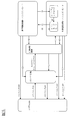
- FIG. 3 is a block diagram of the map database 13 and the control device 18.
- the control device 18 has a first memory 18a, a second memory 18b, a data acquisition unit 18c, and a travel control unit 18d.
- the first memory 18a is a memory that temporarily stores the data acquired from the map database 13.
- the storage capacity of the first memory 18a is smaller than the storage capacity of the map database 13.
- the second memory 18b is a memory that temporarily stores the data acquired from the first memory 18a.
- the storage capacity of the second memory 18b is smaller than the storage capacity of the first memory 18a.
- the data acquisition unit 18c is a functional block of the driving information acquisition function.
- the data acquisition unit 18c saves and deletes the first memory 18a and the second memory 18b. Further, the data acquisition unit 18c acquires data necessary for autonomous control from the data stored in the second memory 18b according to the traveling state of the own vehicle, and outputs the data to the traveling control unit 18d.
- the travel control unit 18d is a functional block of the autonomous travel control function.
- the map database 13 stores data of a specific area such as all over Japan.
- the data stored in the map database 13 is used for route search in the navigation system.
- the data acquisition unit 18c stores the road information within a predetermined range with respect to the current position of the own vehicle in the first memory 18a among the map information stored in the map database 13.
- the data acquisition unit 18c stores the road information from the current position of the own vehicle to a predetermined distance (for example, 2 km) ahead in the first memory 18a.
- the vehicle information stored in the first memory 18a is information such as a lane center line, a lane mark (white line), a speed limit, and a sign.
- the data acquisition unit 18c stores the road information in a predetermined range with respect to the current position of the own vehicle in the second memory 18b among the road information stored in the first memory 18a.
- the data acquisition unit 18c stores the road information from the current position of the own vehicle to a predetermined distance (for example, 1 km) ahead in the second memory 18b.
- a predetermined distance for example, 1 km
- the predetermined distance to be stored in the memory is the second memory 18b rather than the first memory 18a. Is shorter.
- the data acquisition unit 18c acquires only the road information necessary for autonomous control from the road information stored in the second memory 18b, and outputs it to the travel control unit 18d. At this time, if the travel road of the vehicle can be limited among the plurality of lanes, the data acquisition unit 18c selectively acquires the road information of the road on which the vehicle travels and outputs it to the travel control unit 18d. .. In other words, the data acquisition unit 18c extracts the road information stored in the second memory 18b when the traveling road of the vehicle can be limited among the plurality of vehicles, and transmits the extracted road information to the traveling control unit 18d. Output.
- the data acquisition unit 18c limits the driving road of the vehicle from a plurality of lanes based on the driver's operation and / or the traveling route. For example, when the road ahead of the current position of the own vehicle is branched and the driver operates the blinker and blinks the blinker lamp on the left side, the data acquisition unit 18c will perform the road on the left side of the branched roads. Limited to.
- the case where the vehicle leaves the tollhouse from the highway and heads for the general road is set and the own vehicle is approaching the interchange will be explained as an example.
- the vehicle The driving road can be limited.
- the road information of the main line and the road information of the branched road are stored in the second memory 18b, and the data acquisition unit 18c selectively selects the road information of the branched road due to the blinking of the winker. And outputs the selected road information to the travel control unit 18d.
- Road information is selectively acquired and output to the traveling control unit 18d. Since the road information of the lane that is not related to the autonomous control of the own vehicle is not input to the travel control unit 18d and the road information necessary for the autonomous control of the own vehicle is input, the calculation load in the travel control unit 18d is increased. Can be reduced.
- the autonomous driving control function of the control device 18 is a function that autonomously controls the driving of the own vehicle without depending on the operation of the driver.
- the autonomous driving speed control function that autonomously controls the traveling speed of the own vehicle and the steering of the own vehicle are autonomous. Includes an autonomous steering control function to control.
- the autonomous speed control function and the autonomous steering control function of the present embodiment will be described.
- the autonomous speed control function detects a preceding vehicle, it follows the preceding vehicle while performing inter-vehicle distance control so as to maintain the inter-vehicle distance according to the vehicle speed, with the vehicle speed set by the driver as the upper limit.
- the vehicle is not detected, it is a function to drive at a constant speed at the vehicle speed set by the driver.
- the former is also called inter-vehicle distance control, and the latter is also called constant speed control.
- the function of automatically setting the speed of the speed limit sign to the set vehicle speed may be included.
- the driver To activate the autonomous speed control function, the driver first operates the resume accelerator switch 162 or the set coast switch 163 of the input device 16 shown in FIG. 2 to input a desired traveling speed. For example, if the own vehicle is running at 70 km / h and the set coast switch 163 is pressed, the current running speed is set as it is, but if the speed desired by the driver is 80 km / h, resume acceleration The set speed may be increased by pressing the switch 162 multiple times. On the contrary, assuming that the speed desired by the driver is 60 km / h, the set coast switch 163 may be pressed a plurality of times to lower the set speed.
- inter-vehicle distance desired by the driver may be selected by operating the inter-vehicle adjustment switch 165 of the input device 16 shown in FIG. 2 and selecting one from a plurality of stages of settings such as short distance, medium distance, and long distance.
- the constant speed control uses a sensor 11 such as a front radar that detects an obstacle in front of the own vehicle to detect that there is no preceding vehicle in front of the lane in which the own vehicle is traveling, and the driving is set by the driver.
- the drive control device 17 controls the operation of the drive mechanism such as the engine and the brake while feeding back the vehicle speed data from the vehicle speed sensor so as to maintain the speed.
- the inter-vehicle distance control is based on the presence of a preceding vehicle (the vehicle immediately in front of the own vehicle) in front of the lane in which the own vehicle is traveling by using a sensor 11 such as a front radar that detects an obstacle in front of the own vehicle and the inter-vehicle distance.
- the drive control device 17 feeds back the inter-vehicle distance data from the sensor 11 (front radar) so as to maintain the inter-vehicle distance set by the driver with the traveling speed set by the driver as the upper limit while detecting the above. It controls the operation of drive mechanisms such as the engine and brakes.
- the own vehicle also stops following the preceding vehicle, and if the preceding vehicle starts within 30 seconds after the own vehicle stops, the own vehicle also starts. , Starts follow-up driving by inter-vehicle distance control again. If your vehicle has stopped for more than 30 seconds, it will not start automatically even if the preceding vehicle starts, and if you press the resume acceleration switch 162 or depress the accelerator pedal after the preceding vehicle starts. , Starts follow-up driving by inter-vehicle distance control again.
- the autonomous steering control function is a function that executes steering control of the own vehicle by controlling the operation of the steering actuator.
- a lane keeping function (lane width direction maintenance function) that controls the steering to drive near the center of the lane and assists the driver in steering, and controls the steering when the driver operates the winker lever, which is necessary for changing lanes.
- Lane change support function that supports various steering operations, when a vehicle slower than the set vehicle speed is detected ahead, the display confirms whether to overtake the driver, and if the driver operates the consent switch, the steering is controlled and the overtaking operation is performed.
- the driver will be asked if he / she will change lanes.
- the route driving support function is a function that controls the steering, vehicle speed, and blinker so that the own vehicle travels along the traveling route when the traveling route to the destination is set.
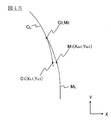
- FIG. 4A is a diagram for explaining a traveling locus and a target point when a vehicle travels from the main lane to the branch lane on a branch road.
- FIG. 4B is a schematic view showing a part of the traveling locus and the target point of FIG. 4A.
- the X-axis shows the coordinate axes in the lateral direction (vehicle width direction) of the vehicle
- the Y-axis shows the coordinate axes in the vehicle traveling direction on the main line.
- lane A is a branch lane connecting the main lane to the tollhouse.
- the main lane includes lanes B and C, and lane C is the overtaking lane.
- the control device 180 calculates the travel route to the destination.
- the control device 180 executes a lane keeping function and a lane change function in order to travel according to the traveling route.
- the control device 180 executes each function based on the information recognized by the camera image and the map information stored in the database 13. Since the information that can be recognized by the camera image indicates the actual driving environment, when the lane mark can be recognized from the camera image, the control device 180 preferentially uses the information recognized from the camera image to vehicle the vehicle. Autonomously control. In the branch road as shown in FIG. 4A, a dotted boundary line is drawn between the main lane and the branch lane, but many vehicles heading from the main lane to the branch lane travel across this boundary line.
- the control device 180 autonomously controls the vehicle based on the map information stored in the database 13.
- an area where a feature to be recognized for autonomous control, such as a lane mark and / or an obstacle, cannot be recognized from the camera image is specified in advance as an unrecognizable area.
- the unrecognizable area indicates an area where the external situation of the vehicle cannot be recognized by the camera image.
- Information on the size and position of the unrecognizable area is stored in advance in the map database 13.
- the control device 180 refers to the map database 13 and determines whether or not there is an unrecognizable area on the travel route calculated by the vehicle. If the unrecognizable area is on the travel route, the vehicle will travel in the unrecognizable area. In the unrecognizable area, the lane keeping function cannot be activated by using the information recognized from the camera image.
- the control device 180 uses the road information stored in the map database instead of the camera image to lane. Execute the keep function and / or the lane change function. That is, when the vehicle is not traveling in the unrecognizable area, the control device 180 autonomously controls the vehicle using the information recognized from the camera image, and when traveling in the unrecognizable area, the control device 180 is the camera. Instead of images, the road information stored in the map database is used to autonomously control the vehicle.
- the center line of the lane included in the map information is used as the traveling locus of the vehicle.
- the target point is set at a position separated from the current position of the own vehicle by a predetermined traveling time (for example, 1.25 seconds).
- a predetermined traveling time for example, 1.25 seconds.
- the autonomous control based on the camera image is switched to the autonomous control based on the map information before the vehicle enters the unrecognizable area. ing.
- the control device 180 specifies a predetermined area R including the branch path as an unrecognizable area.
- the unrecognizable area A includes at least a boundary line between the main lane and the branch lane and a part of the branch lane.
- the control device 180 sets the lane change start point P because it is necessary to change lanes from the main lane to the branch lane at the branch road of the interchange.
- the lane change start point is a point at which steering control is started so that the vehicle moves in the lateral direction (vehicle width direction).
- the control device 180 sets the lane change start point P on the lane B.
- the lane change start point P is set at a position in front of the point O where the branch lane starts by a predetermined distance.
- the lane change start point P is set on lane B.
- the lane change start points are set on lane B and lane C, respectively.
- the distance from the lane change start point set on lane C to the lane change start point set on lane B is the direction of travel of the vehicle, and the branch lane starts from the lane change start point set on lane B.
- the distance is set longer than the distance to the point O.
- the control device 180 sets an intention confirmation point Q for confirming the user's intention to change lanes at a position a predetermined distance before the lane change start point P.
- the control device 180 confirms with the driver whether to change lanes by displaying the display.
- the data acquisition unit 18c of the control device 180 acquires the road information of the lane A, which is a branch lane, and does not acquire the road information of the lanes B and C.
- the data acquisition unit 18c of the control device 180 acquires the road information of the lane A, which is a branch lane, and the roads of the lanes B and C. Do not get information.
- the timing at which the data acquisition unit 18c of the control device 180 acquires the road information of the lane A may be at the start of blinking of the blinker or after the start of blinking of the blinker. Since the blinker starts blinking when the own vehicle reaches the lane change start point P, the data acquisition unit 18c of the control device 180 may acquire the information of the lane A in accordance with the blinking of the blinker. ..
- Lane B is the same road on which the vehicle is currently traveling.
- the control device 180 uses the lane keeping function to recognize the lane mark from the camera image and then controls the steering so as to travel near the center of the lane B. Then, when the intention to change lanes is confirmed and the own vehicle reaches the lane change start point P, the control device 180 recognizes the lane mark from the camera image by the lane change support function, and then changes the lane.
- the steering is controlled so that the position of the vehicle passes through the target point on the traveling locus. As a result, the vehicle moves laterally so that the distance between the current position of the vehicle and the lane mark on the right side increases.
- the control device 180 sets a control switching point at the branch road while executing the camera control in preparation for switching from the camera control to the map control.
- the control switching points are, for example, the center line between the left and right lane marks recognized from the camera image (or an extension line obtained by extending the center line) and the lane included in the map information (the lane including the branch lane). It is set at the intersection with the center line (or an extension line that extends the center line).
- the control switching point is set at a position where the lateral deviation from the extended line (extended line) is less than a predetermined length.
- the control switching point is outside the unrecognizable area and is set at a position on the center line of the lane B.
- the control switching point is set at the position of the lane change start point P.
- the control device 180 switches from camera control to map control.
- autonomous control of the vehicle is executed so that the vehicle travels along the center line of the lane included in the road information A, and the vehicle travels on the branch lane.
- the control device 180 calculates the timing for switching from map control to camera control while the vehicle is traveling in the unrecognizable area or after the vehicle has passed the unrecognizable area.
- the control device 180 calculates a target point (hereinafter, also referred to as a first target point) using a camera image while traveling in the unrecognizable area or after passing through the unrecognizable area. If the lane mark cannot be stably recognized from the camera image in the unrecognizable area, the first target point is calculated after the lane mark can be recognized. Further, the control device 180 calculates a target point (hereinafter, also referred to as a second target point) using the road information A. Then, the control device 180 switches from map control to camera control when the difference between the first target point and the second target point is equal to or less than a predetermined value.
- the curve C L represents the running locus is calculated from the camera image
- the curve M L represents the running locus is calculated from the map information (road information A).
- the first target point C is represented by the position (X c , Y c )
- the second target point M is represented by the position (X M , Y M ).
- the angle ( ⁇ C ) of the angle formed by the line segment connecting the origin and the first target point C and the X axis is calculated.
- the current position of the vehicle is set as the origin
- the angle ( ⁇ M ) of the angle formed by the line segment connecting the origin and the second target point M and the X axis is calculated.
- the angle ( ⁇ C , ⁇ M ) is calculated by the following equations (1) and (2).
- the control device 180 determines whether or not the condition of the following equation (3) is satisfied.
- control device 180 switches from map control to camera control and autonomously makes the vehicle so that the position of the vehicle passes the first target point. Control.
- the angle ( ⁇ C1 ) calculated with respect to the first target point C 1 and the angle ( ⁇ M1 ) calculated with respect to the second target point M 1 and the difference are threshold values ( ⁇ th). ) Greater. Therefore, at the timing when the second target point M 1 is calculated, the control device 180 continues the map control. The angle ( ⁇ C2 ) calculated with respect to the first target point C 2 and the angle ( ⁇ M2 ) calculated with respect to the second target point M 2 and the difference are smaller than the threshold value ( ⁇ th ). Therefore, the control device 180 switches from map control to camera control at the timing when the own vehicle passes the first target point C 2 . As a result, it is possible to prevent the behavior of the vehicle from becoming large when switching from map control to camera control.
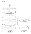
- FIG. 5 is a block diagram showing a state transition of each function established in the control device 18.
- the system means an autonomous driving control system realized by the control device 18.
- the main switch 161 of FIG. 2 When the main switch 161 of FIG. 2 is turned on from the system OFF state shown in the figure, the system goes into the standby state. From this standby state, the autonomous speed control is activated by turning on the set coast switch 163 or the resume acceleration switch 162 of FIG.
- the above-mentioned constant speed control or inter-vehicle distance control is started, and the driver can drive his / her own vehicle simply by operating the steering wheel without stepping on the accelerator or the brake.
- the mode transitions to the lane keep mode of the autonomous steering control / hands-on mode.
- the condition (1) is not particularly limited, but the lane marks on both sides of the own vehicle are detected, the driver has the steering wheel, the vehicle is traveling near the center of the lane, and the winker is activated. Not doing, the wiper is not operating at high speed (HI), if there is a high-precision map, there are no tollhouses, exits, confluences, intersections, lane reduction points, etc. within about 200 m ahead. It can be illustrated that the conditions are satisfied.
- the hands-on mode refers to a mode in which the autonomous steering control does not operate unless the driver holds the steering wheel
- the hands-off mode refers to a mode in which the autonomous steering control operates even if the driver releases the steering wheel.
- condition (2) in FIG. 5 If the condition (2) in FIG. 5 is satisfied while the lane keep mode of the autonomous steering control / hands-on mode is being executed, the mode transitions to the lane keep mode of the autonomous steering control / hands-off mode.
- the condition (2) is not particularly limited, but the vehicle is traveling on a motorway, is traveling on a road structurally separated from the oncoming lane, and is traveling on a road having a high-precision map. You must be driving, you are driving at a vehicle speed below the speed limit, the GPS signal is valid, the driver has a handle, the driver is facing forward, and the toll booth is within about 800 m ahead.
- condition (3) of FIG. 5 is satisfied while the lane keep mode of the autonomous steering control / hands-off mode is being executed, the mode transitions to the lane keep mode of the autonomous steering control / hands-on mode.
- the condition (3) is not particularly limited, but the vehicle is traveling on a road other than a motorway, is traveling on a two-way traffic section, and is traveling on a road without a high-precision map.
- condition (4) in FIG. 5 is satisfied while the lane keep mode of the autonomous steering control / hands-off mode is being executed, the autonomous steering control is stopped and the process shifts to the autonomous speed control.
- the condition (4) is not particularly limited, but one of the following is that the lane marks on both sides of the own vehicle are not detected for a certain period of time, the driver operates the steering wheel, and the wiper operates at high speed (HI). It can be illustrated that the condition of is satisfied. Further, if the condition (5) of FIG. 5 is satisfied while the lane keep mode of the autonomous steering control / hands-off mode is being executed, the autonomous steering control and the autonomous speed control are stopped and the state shifts to the standby state.
- the condition (5) is not particularly limited, but the driver operates the brake, the driver operates the cancel switch 164 in FIG. 2, the door of the own vehicle is opened, and the driver's seat belt is released. That, the seating sensor detected that the driver had left the driver's seat, the select lever was other than "D” or "M”, the parking brake was activated, and the vehicle's electronic stability control was turned off. , The electronic stability control has been activated, the snow mode has been turned on, the emergency brake has been activated, the vehicle has stopped due to vehicle speed control, and the vehicle has been stopped for about 3 minutes. However, it detected poor visibility such as dirt, backlight, rain / fog, etc.
- the front radar detected shielding, radio interference, the front radar detected misalignment, and the side radar It can be exemplified that any of the conditions such as shielding, detection of radio interference, and detection of axis deviation by the side radar is satisfied.
- condition (6) in FIG. 5 is satisfied while the autonomous steering control / hands-on mode is being executed, the autonomous steering control is stopped and the process shifts to the autonomous speed control.
- the condition (6) is not particularly limited, but the lane marks on both sides of the own vehicle are no longer detected, the driver operates the steering wheel, the driver operates the blinker, and the wiper operates at high speed (HI).
- HI high speed
- One of the conditions was that the vehicle was in the tollhouse section when there was a high-precision map, and that the front camera detected poor visibility that could not correctly recognize the object due to dirt, backlight, rain, fog, etc. It can be illustrated that it is established. Further, if the condition (7) of FIG.
- the condition (7) is not particularly limited, but the driver operates the brake, the driver operates the cancel switch 164 in FIG. 2, the door of the own vehicle is opened, and the driver's seat belt is released. That, the seating sensor detected that the driver had left the driver's seat, the select lever was other than "D" or "M”, the parking brake was activated, and the vehicle's electronic stability control was turned off. , The electronic stability control was activated, the snow mode was turned on, the emergency brake was activated, the vehicle stopped due to vehicle speed control, and then the stopped state continued for about 3 minutes, front radar. It can be exemplified that any of the conditions such as shielding, detection of radio interference, and detection of axis deviation by the front radar is satisfied.
- the condition (8) in FIG. 5 is satisfied while the autonomous speed control is being executed, the state transitions to the standby state.
- the condition (8) is not particularly limited, but the driver operates the brake, the driver operates the cancel switch 164 in FIG. 2, the door of the own vehicle is opened, and the driver's seat belt is released. That, the seating sensor detected that the driver had left the driver's seat, the select lever was other than "D” or "M”, the parking brake was activated, and the vehicle's electronic stability control was turned off. , The electronic stability control was activated, the snow mode was turned on, the emergency brake was activated, the vehicle stopped due to vehicle speed control, and the stopped state continued for about 3 minutes, front radar. It can be exemplified that any of the conditions such as shielding, detection of radio interference, and detection of axis deviation by the front radar is satisfied.
- condition (9) in FIG. 5 is satisfied while the lane keep mode of the autonomous steering control / hands-off mode is being executed, the mode transitions to the lane change mode of the autonomous steering control / hands-on mode.
- This condition (9) is not particularly limited, but is one of the conditions that the driver presses the lane change support switch 166 in FIG. 2 and the driver operates the blinker when the system proposes a lane change. Can be exemplified as the establishment of.
- condition (10) in FIG. 5 is satisfied while the lane change mode of the autonomous steering control / hands-on mode is being executed, the mode transitions to the lane keep mode of the autonomous steering control / hands-on mode.
- the condition (10) is not particularly limited, but the speed limit is exceeded before the start of the lane change operation (hereinafter referred to as LCP), and the driver holds the steering wheel and depresses the accelerator pedal before the start of the LCP.
- LCP could not be started within 10 seconds after pressing the lane change support switch 166 during the lane change proposal when there was a slow vehicle ahead, and the lane change support switch during the lane change proposal to drive according to the route.
- the main switch 161 is turned off in any of the autonomous steering control / hands-off mode, the autonomous steering control / hands-on mode, the autonomous speed control, and the standby state, the system is turned off.
- FIGS. 6A to 6C are flowcharts showing the traveling control process according to the present embodiment.
- the travel control process described below is executed by the control device 18 at predetermined time intervals.
- the autonomous driving control function of the control device 18 executes autonomous speed control and autonomous steering control, and the width direction of the own vehicle so that the own vehicle travels in the lane at a speed set by the driver. While the lane keep control for controlling the traveling position in the above is being performed, it is assumed that the interchange is approaching and the vehicle is traveling on a route that requires a lane change in order to travel according to the traveling route.
- step S1 of FIG. 6A it is determined whether or not the main switch 161 of the control device 18 is ON, and if the main switch 161 is OFF, step S1 is repeated until it is turned ON. If the main switch 161 is ON, the process proceeds to step S2, and it is determined whether or not the traveling speed is set by the driver. If the traveling speed is not set, the process returns to step S1 and steps S1 and S2 are repeated until the traveling speed is set. The traveling speed is set by the driver by operating the resume acceleration switch 162 or the set coast switch 163 of the input device 16 shown in FIG. 2 to input a desired traveling speed.
- step S3 the front radar (sensor 11) that detects an obstacle in front of the own vehicle is used to detect whether or not there is a preceding vehicle in front of the lane in which the own vehicle is traveling, and if there is a preceding vehicle. Proceeds to step S4 to execute inter-vehicle distance control, and if there is no preceding vehicle, proceeds to step S5 to execute constant speed control.
- the driver can drive the own vehicle at a desired speed simply by operating the steering wheel without stepping on the accelerator or the brake.
- step S6 Whether or not the condition (1) for transitioning to the above-mentioned autonomous steering control / hands-on mode lane keep mode is satisfied in step S6 while the inter-vehicle distance control in step S4 or the constant speed control in step S5 is being executed. To judge. If the condition (1) is satisfied, the process proceeds to step S7, and if the condition (1) is not satisfied, the process returns to step S2.
- step S7 the front radar (sensor 11) that detects an obstacle in front of the own vehicle is used to detect whether or not there is a preceding vehicle in front of the lane in which the own vehicle is traveling, and if there is a preceding vehicle. Proceeds to step S8 to execute the inter-vehicle distance control / lane keep mode, and if there is no preceding vehicle, proceeds to step S9 to execute the constant speed control / lane keep mode.
- the autonomous control in step S8 or step S9 is a control based on a camera image.
- step S10 of FIG. 6B While the inter-vehicle distance control / lane keep mode in step S8 or the constant speed control / lane keep mode in step S9 is being executed, it is determined in step S10 of FIG. 6B that the destination is set. If the destination has not been set, the process returns to step S2 of FIG. 6A. If the destination has been set, the process proceeds to step S11 to execute route traveling support. In route driving support, when it is necessary to change lanes in order to drive according to the driving route, a lane change start point and an intention confirmation point for confirming the intention to change lanes are set. In step S12, the map information stored in the map database 13 is referred to, and an unrecognizable area is specified on the traveling route.
- step S13 it is determined whether or not the current position of the vehicle has reached the intention confirmation point, and if it has not reached the intention confirmation point, the process returns to step S11, and if it reaches the intention confirmation point, the lane is changed.
- a display screen is displayed on the display to confirm the driver's intention as to whether or not to do so.
- step S14 it is determined whether or not there is an intention to change lanes. After the display is displayed, if the driver operates the consent switch, it is determined that there is an intention to change lanes, and the process proceeds to step S15. If the consent switch is not operated, it is determined that there is no intention to change lanes. , Step S18.
- step S15 it is determined whether or not the lane changeable condition is satisfied.
- the lane changeable condition is the condition shown in FIG. 5 (9). However, if the conditions of FIG. 5 (9) include the recognition of the lane mark and the space of the adjacent lane required for changing lanes, the lane set in the determination process of step S15. These conditions are excluded from the modifiable conditions. If the lane changeable condition is satisfied, the process proceeds to step S16, and if the lane changeable condition is not satisfied, the process proceeds to step S19.
- step S16 it is determined whether or not the current position of the vehicle has reached the lane change start point, and if the vehicle has reached the lane change start point, the process proceeds to step S17, and if the vehicle has not reached the lane change start point, the process proceeds to step S17. Return to step S16. If the vehicle does not follow the travel route before reaching the lane change start point (for example, when the vehicle moves to a lane adjacent to the current lane), the process proceeds to step S19.
- step S17 the control device 180 starts blinking the blinker.
- step S18 the control device 180 acquires the road information of lane A, which is a branch lane, from the road information stored in the second memory 18b, and proceeds to step S20. If the current position of the vehicle reaches the intention confirmation point or the lane change start point and the information on the branch lane has already been acquired, the road information of the lane A ahead of the already acquired branch lane is acquired. To do.
- step S19 the control device 180 acquires the road information of the main lanes B and C among the road information stored in the second memory 18b, and returns to step S2 of FIG. 6A.
- step S20 the autonomous control based on the camera image is switched to the autonomous control based on the map information, and the lane change support is executed.
- the lane change support in step S20 is executed in the hands-on mode.
- the target point M is calculated using the road information of the lane A, and the steering is controlled so that the vehicle passes the target point M.
- the calculation of the target point M is repeated at a predetermined cycle, and the steering is controlled so that the vehicle passes each of the calculated target points M.
- step S21 it is determined whether or not the lane mark can be recognized from the camera image, and if the lane mark can be recognized, the process proceeds to step S22, and if the lane mark cannot be recognized, the process returns to step S20.
- the determination timing in step S21 may be performed after a predetermined time has elapsed from the time when the autonomous control based on the camera image is switched to the autonomous control based on the map information, for example.
- the length of the predetermined time may be set to be equal to or longer than the length of time from the start to the completion of the lane change.
- step S22 the target points C and M are calculated. That is, the target point C is calculated in addition to the target point M.
- step S23 the angle ( ⁇ C , ⁇ M ) is calculated.
- step S24 the difference between the first target point and the second target point (
- the autonomous control based on the map information is switched to the autonomous control based on the camera image (S29).
- the lane change in the branch road is completed, and the autonomous control based on the map information is switched to the autonomous control based on the camera image while the vehicle is traveling in the branch lane.
- ) when a is larger than the threshold value ([Delta] [theta] th) is the threshold value ([Delta] [theta] th) larger than the state given It is determined whether or not the time (for example, 10 seconds) has elapsed. If the predetermined time (for example, 10 seconds) has not elapsed, the process returns to step S22, and if the predetermined time (for example, 10 seconds) has elapsed, the autonomous steering control is turned off and the steering operation is switched to the driver.
- the time for example, 10 seconds
- step S20 Since the control flow after step S20 is executed in the hands-on mode, when the automatic steering control is turned off in step S27, the driver is holding the steering wheel, and the driver can smoothly perform the steering operation.
- the difference between the first target point (target point C) and the second target point (target point M) is large. If you switch from map control to camera control in this state, the behavior of the vehicle will increase. Therefore, in the present embodiment, when the difference between the first target point (target point C) and the second target point (target point M) is large for a predetermined time or longer, the autonomous steering control is turned off. Therefore, it is possible to prevent the behavior of the vehicle from becoming large when the control is switched.
- the vehicle travel control device 1 and the travel control method according to the present embodiment when the unrecognizable area is on the travel route of the vehicle, before the vehicle enters the unrecognizable area. , Switch from autonomous control based on camera images (corresponding to "first autonomous control” of the present invention) to autonomous control based on map information (corresponding to "second autonomous control” of the present invention).
- the autonomous control based on the camera image is the autonomous control of the vehicle using the information recognized from the camera image
- the autonomous control based on the map information is the autonomous control of the vehicle using the map information of the map database 13.
- the difference between the first target point and the second target point is equal to or less than a predetermined value after switching from the first autonomous control to the second autonomous control.
- the second autonomous control is switched to the first autonomous control.
- the difference between the first target point and the second target point is larger than the predetermined value after switching from the first autonomous control to the second autonomous control. If the state continues for a predetermined time or longer, the autonomous steering control function is turned off. As a result, it is possible to prevent the map control from being switched to the camera control in a state where the difference between the first target point and the second target point is large, and to prevent the behavior of the vehicle from becoming large.
- the difference between the first target point and the second target point is larger than the predetermined value after switching from the first autonomous control to the second autonomous control. In that case, the second autonomous control is continued. As a result, it is possible to prevent the map control from being switched to the camera control in a state where the difference between the first target point and the second target point is large, and to prevent the behavior of the vehicle from becoming large.
Abstract
車両の走行速度を自律制御する自律速度制御機能と、車両の操舵を自律制御する自律操舵制御機能とを作動させて、車両を自律制御し、車両に設けられたカメラの撮像画像により、車両の外部状況を認識できる場合には、撮像画像から認識された情報を用いて車両を自律制御する第1自律制御を実行し、車両に設けられた記憶媒体に記憶されている地図情報から、車両の外部状況を示す情報を取得し、取得された情報を用いて車両を自律制御する第2自律制御を実行し、撮像画像により車両の外部状況を認識できない認識不可エリアを特定し、認識不可エリアが車両の走行ルート上にある場合には、車両が認識不可エリアに進入する前に、第1自律制御から第2自律制御に切り替える。
Description
本発明は、自律走行制御を含む車両の走行制御方法及び走行制御装置に関する。
本出願は、2019年5月15日に出願された日本国特許出願の特願2019―92431に基づく優先権を主張するものであり、文献の参照による組み込みが認められる指定国については、上記の出願に記載された内容を参照により本出願に組み込み、本出願の記載の一部とする。
本出願は、2019年5月15日に出願された日本国特許出願の特願2019―92431に基づく優先権を主張するものであり、文献の参照による組み込みが認められる指定国については、上記の出願に記載された内容を参照により本出願に組み込み、本出願の記載の一部とする。
車両の運転支援装置において、カメラユニットで自車進行路の左右区画線が認識されていないと判定した場合、自車両の道路地図上の走行車線に記憶されている地図曲率を読み込み、地図曲率、追従対象先行車の走行軌跡に基づく先行曲率、及び自車車速に基づいて推定横位置偏差を求め、推定横位置偏差を自車横位置に加算して自車両を走行車線に沿って走行される目標ハンドル角を設定するものが知られている(特許文献1)。
しかしながら、従来技術では、カメラで左右区間線が認識されていないと判定された後に、道路地図データベースから地図曲率を読み込むため、カメラの認識結果を用いた車両制御から、道路地図データベースのデータを用いた車両制御への切り換えが遅くなり、車両の挙動が大きくなるという問題がある。
本発明が解決しようとする課題は、車両の自律制御を切り替える際に、車両の挙動を抑制できる車両の走行制御方法及び走行制御装置を提供することである。
本発明は、認識不可エリアが車両の走行ルート上にある場合には、車両が認識不可エリアに進入する前に、カメラ画像から認識された情報を用いた車両の自律制御から記憶媒体の地図情報を用いた車両の自律制御に切り替えることで、上記課題を解決する。
本発明によれば、車両の自律制御を切り替える際に、車両の挙動を抑制できる。
図1は、本実施形態に係る車両の走行制御装置1の構成を示すブロック図である。本実施形態の車両の走行制御装置1は、本発明に係る車両の走行制御方法を実施する一実施の形態でもある。図1に示すように、本実施形態に係る車両の走行制御装置1は、センサ11と、自車位置検出装置12と、地図データベース13と、車載機器14と、提示装置15と、入力装置16と、駆動制御装置17と、制御装置18とを備える。これらの装置は、相互に情報の送受信を行うために、たとえばCAN(Controller Area Network)その他の車載LANによって接続されている。
センサ11は、自車両の走行状態を検出する。たとえば、センサ11として、自車両の前方を撮像する前方カメラ、自車両の後方を撮像する後方カメラ、自車両の前方の障害物を検出する前方レーダー、自車両の後方の障害物を検出する後方レーダー、自車両の左右の側方に存在する障害物を検出する側方レーダー、自車両の車速を検出する車速センサ、ドライバーがハンドルを持っているか否かを検出するタッチセンサ(静電容量センサ)およびドライバーを撮像する車内カメラなどが挙げられる。なお、センサ11として、上述した複数のセンサのうち1つを用いる構成としてもよいし、2種類以上のセンサを組み合わせて用いる構成としてもよい。センサ11の検出結果は、所定時間間隔で制御装置18に出力される。
自車位置検出装置12は、GPSユニット、ジャイロセンサ、および車速センサなどから構成され、GPSユニットにより複数の衛星通信から送信される電波を検出し、対象車両(自車両)の位置情報を周期的に取得するとともに、取得した対象車両の位置情報と、ジャイロセンサから取得した角度変化情報と、車速センサから取得した車速とに基づいて、対象車両の現在位置を検出する。自車位置検出装置12により検出された対象車両の位置情報は、所定時間間隔で制御装置18に出力される。
地図データベース13は、各種施設や特定の地点の位置情報を含む三次元高精度地図情報を格納し、制御装置18からアクセス可能とされたメモリである。地図データベース13に格納された三次元高精度地図情報は、データ取得用車両を用いて実際の道路を走行した際に検出された道路形状に基づく三次元地図情報であり、地図情報とともに、カーブ路及びそのカーブの大きさ(たとえば曲率又は曲率半径)、道路の合流地点、分岐地点、料金所、車線数の減少位置、サービスエリア/パーキングエリアなどの詳細かつ高精度の位置情報が、三次元情報として関連付けられた地図情報である。
車載機器14は、車両に搭載された各種機器であり、ドライバーにより操作されることで動作する。このような車載機器としては、ステアリング、アクセルペダル、ブレーキペダル、ナビゲーション装置、方向指示器、ワイパー、ライト、クラクション、その他の特定のスイッチなどが挙げられる。車載機器14がドライバーにより操作された場合に、その情報が制御装置18に出力される。
提示装置15は、たとえば、ナビゲーション装置が備えるディスプレイ、ルームミラーに組み込まれたディスプレイ、メーター部に組み込まれたディスプレイ、フロントガラスに映し出されるヘッドアップディスプレイ、オーディオ装置が備えるスピーカー、および振動体が埋設された座席シート装置などの装置である。提示装置15は、制御装置18の制御に従って、後述する提示情報および車線変更情報をドライバーに報知する。
入力装置16は、たとえば、ドライバーの手動操作による入力が可能なボタンスイッチ、ディスプレイ画面上に配置されたタッチパネル、又はドライバーの音声による入力が可能なマイクなどの装置である。本実施形態では、ドライバーが入力装置16を操作することで、提示装置15により提示された提示情報に対する設定情報を入力することができる。図2は、本実施形態の入力装置16の一部を示す正面図であり、ステアリングホイールのスポーク部などに配置されたボタンスイッチ群からなる一例を示す。図示する入力装置16は、制御装置18が備える自律速度制御機能及び自律操舵制御機能のON/OFFを設定する際に使用するボタンスイッチであり、メインスイッチ161と、リジューム・アクセラレートスイッチ162と、セット・コーストスイッチ163と、キャンセルスイッチ164と、車間調整スイッチ165と、車線変更支援スイッチ166とを備える。
メインスイッチ161は、制御装置18の自律速度制御機能及び自律操舵制御機能を実現するシステムの電源をON/OFFするスイッチである。リジューム・アクセラレートスイッチ162は、自律速度制御機能の作動をOFFしたのちOFF前の設定速度で自律速度制御機能を再開したり、設定速度を上げたり、先行車に追従して停車したのち再発進させたりするスイッチである。セット・コーストスイッチ163は、走行時の速度で自律速度制御機能を開始したり、設定速度を下げたりするスイッチである。キャンセルスイッチ164は、自律速度制御機能をOFFするスイッチである。車間調整スイッチ165は、先行車との車間距離を設定するためのスイッチであり、たとえば短距離・中距離・長距離といった複数段の設定から1つを選択するスイッチである。車線変更支援スイッチ166は、制御装置18が車線変更の開始をドライバーに確認した場合に車線変更の開始を指示する(承諾する)ためのスイッチである。
なお、図2に示すボタンスイッチ群以外にも、方向指示器やその他の車載機器14のスイッチを入力装置16として用いることもでき、制御装置18が自動で車線変更を行うか否かの問い合わせに対して、ドライバーが方向指示器のスイッチをオンにすることで、車線変更の承諾乃至許可を入力する構成とすることもできる。なお、入力装置16により入力された設定情報は、制御装置18に出力される。
駆動制御装置17は、自車両の走行を制御する。たとえば、駆動制御装置17は、自律速度制御機能により、自車両が設定速度で定速走行したり、先行車に追従走行したりする場合には、自車両が設定速度となるように、又は先行車が存在する場合には自車両と先行車との車間距離が一定距離となるように、加減速度および走行速度を実現するための駆動機構の動作(エンジン自動車にあっては内燃機関の動作、電気自動車系にあっては走行用モータの動作を含み、ハイブリッド自動車にあっては内燃機関と走行用モータとのトルク配分も含む)およびブレーキ動作を制御する。また、自律操舵制御機能により、自車両が走行する車線(以下、自車線ともいう。)のレーンマークを検出し、自車両が自車線内の、たとえば中央を走行するように、自車両の幅員方向における走行位置を制御するレーンキープ制御を行う場合、車線変更支援機能、追い越し支援機能又はルート走行支援機能により、自車両が先行車の追い越しや走行方向の変更などの自動車線変更制御を行う場合、右左折支援機能により、交差点などにおいて右折又は左折する走行制御を行う場合には、加減速度および走行速度を実現するための駆動機構の動作並びにブレーキ動作に加えて、ステアリングアクチュエータの動作を制御することで、自車両の操舵制御を実行する。なお、駆動制御装置17は、後述する制御装置18の指示により自車両の走行を制御する。また、駆動制御装置17による走行制御方法として、その他の公知の方法を用いることもできる。
制御装置18は、自車両の走行を制御するためのプログラムを格納したROM(Read Only Memory)と、このROMに格納されたプログラムを実行するCPU(Central Processing Unit)と、アクセス可能な記憶装置として機能するRAM(Random Access Memory)とから構成される。なお、動作回路としては、CPU(Central Processing Unit)に代えて又はこれとともに、MPU(Micro Processing Unit)、DSP(Digital Signal Processor)、ASIC(Application Specific Integrated Circuit)、FPGA(Field Programmable Gate Array)などを用いることができる。
制御装置18は、ROMに格納されたプログラムをCPU(プロセッサ)により実行することにより、自車両の走行状態に関する情報を取得する走行情報取得機能と、自車両の走行速度及び/又は操舵を自律制御する自律走行制御機能(自車両の走行速度を自律制御する自律速度制御機能と、自車両の操舵を自律制御する自律操舵制御機能を含む。)を実現する。以下、制御装置18が備える各機能について説明する。
制御装置18の走行情報取得機能は、自車両の走行状態に関する走行情報を取得する機能である。たとえば、制御装置18は、走行情報取得機能により、センサ11に含まれる前方カメラおよび後方カメラにより撮像された車両外部の画像情報や、前方レーダー、後方レーダー、および側方レーダーによる検出結果を、走行情報として取得する。また、制御装置18は、走行情報取得機能により、センサ11に含まれる車速センサにより検出された自車両の車速情報や、車内カメラにより撮像されたドライバーの顔の画像情報も走行情報として取得する。
さらに、制御装置18は、走行情報取得機能により、自車両の現在位置の情報を走行情報として自車位置検出装置12から取得する。また、制御装置18は、走行情報取得機能により、カーブ路及びそのカーブの大きさ(たとえば曲率又は曲率半径)、合流地点、分岐地点、料金所、車線数の減少位置、サービスエリア(SA)/パーキングエリア(PA)などの位置情報を走行情報として地図データベース13から取得する。加えて、制御装置18は、走行情報取得機能により、ドライバーによる車載機器14の操作情報を、走行情報として車載機器14から取得する。
ここで、走行情報取得機能について、図3を用いて説明する。図3は、地図データベース13及び制御装置18のブロック図である。制御装置18は、第1メモリ18a、第2メモリ18b、データ取得部18c、及び走行制御部18dを有している。第1メモリ18aは、地図データベース13から取得したデータを一時的に記憶するメモリである。第1メモリ18aの記憶容量は、地図データベース13の記憶容量よりも小さい。第2メモリ18bは、第1メモリ18aから取得したデータを一時的に記憶するメモリである。第2メモリ18bの記憶容量は、第1メモリ18aの記憶容量よりも小さい。
データ取得部18cは、走行情報取得機能の機能ブロックである。データ取得部18cは、第1メモリ18a、第2メモリ18bの保存及び削除を行う。またデータ取得部18cは、自車両の走行状態に応じて、第2メモリ18bに記憶されているデータのうち、自律制御に必要なデータを取得し、走行制御部18dに出力する。走行制御部18dは、自律走行制御機能の機能ブロックである。
地図データベース13は、例えば日本全国等、特定の地域のデータを記憶している。地図データベース13に記憶されているデータは、ナビゲーションシステムにおけるルート検索に用いられる。そして、データ取得部18cは、地図データベース13に記憶された地図情報のうち、自車両の現在位置に対して所定範囲内の道路情報を第1メモリ18aに記憶させる。例えば、データ取得部18cは、自車両の現在位置から所定距離(例えば2km)先までの道路情報を第1メモリ18aに記憶させる。第1メモリ18aに記憶される車両情報は、車線の中心線、レーンマーク(白線)、制限速度、標識などの情報である。
またデータ取得部18cは、第1メモリ18aに記憶された道路情報のうち、自車両の現在位置に対して所定範囲の道路情報を第2メモリ18bに記憶させる。例えば、データ取得部18cは、自車両の現在位置から所定距離(例えば1km)先までの道路情報を第2メモリ18bに記憶させる。自車両の現在位置から所定距離先前の道路情報を第1メモリ18a及び第2メモリ18bに記憶させる場合には、メモリへの記憶対象となる所定距離は、第1メモリ18aよりも第2メモリ18bの方が短くなる。
データ取得部18cは、第2メモリ18bに記憶された道路情報のうち、自律制御に必要な道路情報だけを取得し、走行制御部18dに出力する。このとき、データ取得部18cは、複数の車線のうち車両の走行道路を限定できる場合には、車両の走行が走行する道路の道路情報を選択的に取得して、走行制御部18dに出力する。言い換えると、データ取得部18cは、複数の車両のうち車両の走行道路を限定できる場合には、第2メモリ18bに記憶された道路情報を抽出し、抽出された道路情報を走行制御部18dに出力する。
データ取得部18cは、ドライバーの操作及び/又は走行ルートに基づき、複数の車線から車両の走行道路を限定する。例えば、自車両の現在位置の前方の道路が分岐している場合に、ドライバーがウィンカーを操作し、左側のウィンカーランプを点滅させたときには、データ取得部18cは、分岐した道路のうち左側の道路に限定する。
車両が高速道路から料金所を出て一般道にむかうような走行経路が設定されており、自車両がインターチェンジに近づいている場合を一例として説明する。このような場合には、ドライバーが、本線から分岐された道路(本線から出て料金所まで接続している道路)に向かうために、車線変更区間の手前でウィンカーを操作した場合には、車両の走行道路が限定できる。第2メモリ18bには、本線の道路情報と、分岐された道路の道路情報が記憶されており、データ取得部18cは、ウィンカーの点滅に起因して、分岐された道路の道路情報を選択的に取得し、選択された道路情報を走行制御部18dに出力する。
このように、データ取得部18cは、自車両の現在位置の前方の道路が分岐されており、車両の走行状態、ドライバー操舵、走行ルート等に基づき、自車両の走行道路を限定できる場合には、道路情報を選択的に取得して、走行制御部18dに出力する。走行制御部18dには、自車両の自律制御とは関係のない車線の道路情報が入力されず、自車両の自律制御に必要な道路情報が入力されるため、走行制御部18dにおける演算負荷を軽減できる。
制御装置18の自律走行制御機能は、自車両の走行をドライバーの操作に依ることなく自律制御する機能であり、自車両の走行速度を自律制御する自律速度制御機能と、自車両の操舵を自律制御する自律操舵制御機能とを含む。以下、本実施形態の自律速度制御機能と自律操舵制御機能を説明する。
《自律速度制御機能》
自律速度制御機能は、先行車を検出しているときは、ドライバーが設定した車速を上限にして、車速に応じた車間距離を保つように車間制御を行いつつ先行車に追従走行する一方、先行車を検出していない場合はドライバーが設定した車速で定速走行する機能である。前者を車間制御、後者を定速制御ともいう。なお、走行情報取得機能により、走行車線の制限速度を検出した場合、制限速度標識の速度を自動的に設定車速にする機能を含んでもよい。
自律速度制御機能は、先行車を検出しているときは、ドライバーが設定した車速を上限にして、車速に応じた車間距離を保つように車間制御を行いつつ先行車に追従走行する一方、先行車を検出していない場合はドライバーが設定した車速で定速走行する機能である。前者を車間制御、後者を定速制御ともいう。なお、走行情報取得機能により、走行車線の制限速度を検出した場合、制限速度標識の速度を自動的に設定車速にする機能を含んでもよい。
自律速度制御機能を作動させるには、まずドライバーが、図2に示す入力装置16のリジューム・アクセラレートスイッチ162又はセット・コーストスイッチ163を操作して、所望の走行速度を入力する。たとえば、自車両が70km/hで走行中にセット・コーストスイッチ163を押すと、現在の走行速度がそのまま設定されるが、ドライバーが所望する速度が80km/hであるとすると、リジューム・アクセラレートスイッチ162を複数回押して、設定速度を上げればよい。逆にドライバーが所望する速度が60km/hであるとすると、セット・コーストスイッチ163を複数回押して、設定速度を下げればよい。また、ドライバーが所望する車間距離は、図2に示す入力装置16の車間調整スイッチ165を操作し、たとえば短距離・中距離・長距離といった複数段の設定から1つを選択すればよい。
定速制御は、自車両の前方の障害物を検出する前方レーダーなどのセンサ11を用いて自車両が走行する車線の前方に先行車が存在しないことを検出しながら、ドライバーにより設定された走行速度を維持するように、車速センサによる車速データをフィードバックしながら、駆動制御装置17によりエンジンやブレーキなどの駆動機構の動作を制御するものである。
車間制御は、自車両の前方の障害物を検出する前方レーダーなどのセンサ11を用いて自車両が走行する車線の前方に先行車(自車両の直前の車両)が存在することとその車間距離を検出しながら、ドライバーにより設定された走行速度を上限にして、ドライバーにより設定された車間距離を維持するように、センサ11(前方レーダー)による車間距離データをフィードバックしながら、駆動制御装置17によりエンジンやブレーキなどの駆動機構の動作を制御するものである。なお、車間制御で走行中に先行車が停止した場合は、先行車に続いて自車も停止し、自車が停止した後、たとえば30秒以内に先行車が発進すると、自車も発進し、再び車間制御による追従走行を開始する。自車が30秒を超えて停止している場合は、先行車が発進しても自動で発進せず、先行車が発進した後、リジューム・アクセラレートスイッチ162を押すか又はアクセルペダルを踏むと、再び車間制御による追従走行を開始する。
《自律操舵制御機能》
自律操舵制御機能は、ステアリングアクチュエータの動作を制御することで、自車両の操舵制御を実行する機能である。車線のたとえば中央付近を走行するようにステアリングを制御して、ドライバーのハンドル操作を支援するレーンキープ機能(車線幅員方向維持機能)、ドライバーがウィンカーレバーを操作するとステアリングを制御し、車線変更に必要なステアリング操作を支援する車線変更支援機能、設定車速よりも遅い車両を前方に検出すると、表示によりドライバーに追い越し操作を行うか確認し、ドライバーが承諾スイッチを操作した場合、ステアリングを制御し追い越し操作を支援する追い越し支援機能、ドライバーがナビゲーション装置などに目的地を設定されている場合には、ルートに従って走行するために必要な車線変更地点に到達すると、表示によりドライバーに車線変更を行うか確認し、ドライバーが承諾スイッチを操作した場合、ステアリングを制御し車線変更を支援するルート走行支援機能などが含まれる。
自律操舵制御機能は、ステアリングアクチュエータの動作を制御することで、自車両の操舵制御を実行する機能である。車線のたとえば中央付近を走行するようにステアリングを制御して、ドライバーのハンドル操作を支援するレーンキープ機能(車線幅員方向維持機能)、ドライバーがウィンカーレバーを操作するとステアリングを制御し、車線変更に必要なステアリング操作を支援する車線変更支援機能、設定車速よりも遅い車両を前方に検出すると、表示によりドライバーに追い越し操作を行うか確認し、ドライバーが承諾スイッチを操作した場合、ステアリングを制御し追い越し操作を支援する追い越し支援機能、ドライバーがナビゲーション装置などに目的地を設定されている場合には、ルートに従って走行するために必要な車線変更地点に到達すると、表示によりドライバーに車線変更を行うか確認し、ドライバーが承諾スイッチを操作した場合、ステアリングを制御し車線変更を支援するルート走行支援機能などが含まれる。
ルート走行支援機能は、目的地までの走行ルートが設定されている場合に、自車両が走行ルートに沿って走行するように、ステアリング、車速、ウィンカーを制御する機能である。図4Aは、分岐路において、車両が本線から分岐車線を走行する際の走行軌跡及び目標点を説明するための図である。図4Bは、図4Aの走行軌跡及び目標点の一部を示す概略図である。図4A及び図4Bにおいて、X軸は車両の横方向(車幅方向)の座標軸を示しており、Y軸は、本線における車両進行方向の座標軸を示している。
例えば、高速道路の本線からインターチェンジで分岐車線に抜けて料金所に向かうような走行ルートが設定されている場合のルート走行支援機能について説明する。図4Aに示すように、車線Aは本線から料金所までを接続する分岐車線である。本線は車線B、Cを含んでおり、車線Cが追越車線である。
制御装置180は、ユーザ等により目的地が設定されると、目的地までの走行ルートを演算する。制御装置180は、走行ルートに従って走行するために、レーンキープ機能、車線変更機能を実行する。制御装置180は、カメラ画像により認識した情報、データベース13に記憶された地図情報に基づき、各機能を実行する。カメラ画像により認識できる情報は、実際の走行環境を示しているため、カメラ画像からレーンマークを認識できる場合には、制御装置180は、カメラ画像から認識された情報を優先的に用いて、車両を自律制御する。図4Aに示すような分岐路において、本線と分岐車線との間には点線の境界線が描かれているが、本線から分岐車線に向かう多くの車両が、この境界線を跨いて走行するため、境界線の一部が消えており、レーンマークをカメラ画像から認識できない可能性がある。またインターチェンジは場所によって形状が様々であり、分岐車線の道路形状が複雑なため、分岐路を走行する際に、レーンマークをカメラ画像から認識できない可能性がある。そして、このようなレーンマークを認識できないエリアで、走行ルートに従って走行するために、制御装置180は、データベース13に記憶された地図情報に基づき、車両を自律制御する。
本実施形態では、レーンマーク及び/又は障害物など、自律制御のために認識すべき地物がカメラ画像から認識できないエリアを、認識不可エリアとして予め特定する。認識不可エリアは、カメラ画像により車両の外部状況を認識できない領域を示している。認識不可エリアの大きさや位置の情報は、地図データベース13に予め記憶されている。制御装置180は、地図データベース13を参照し、車両が演算された走行ルート上に、認識不可エリアが存在するか否かを判定する。認識不可エリアが走行ルート上にある場合には、車両は認識不可エリアを走行することになる。認識不可エリアでは、カメラ画像から認識された情報を用いてレーンキープ機能を作動させることができないため、制御装置180は、カメラ画像の代わりに、地図データベースに記憶された道路情報を用いて、レーンキープ機能及び/又は車線変更機能を実行する。すなわち、認識不可エリアを走行していない場合には、制御装置180はカメラ画像から認識された情報を用いて車両を自律制御し、認識不可エリアを走行する場合には、制御装置180は、カメラ画像の代わりに、地図データベースに記憶された道路情報を用いて、車両を自律制御する。
カメラ画像に基づく自律制御(以下、カメラ制御とも称す)から、地図情報に基づく自律制御(以下、地図制御とも称す)に切り替える際に、カメラ画像により、車両前方の地物を認識できないことを確認した後に、自律制御を切り替えた場合には、車両の挙動が大きくなる可能性がある。車両の自律制御は、車両の走行軌跡上に目標点を設定し、車両の位置が目標点を通過するように、ステアリングを制御する。車両の走行軌跡は演算により算出され、カメラ画像を用いる場合には、例えば、認識された左右のレーンマークの中央線を、車両の走行軌跡(目標軌跡)とする。また、地図情報を用いる場合には、地図情報に含まれる車線の中心線を、車両の走行軌跡とする。目標点は、自車両の現在位置から所定の走行時間(例えば1.25秒)分、離れた位置に設定される。そして、カメラ画像で認識されたレーンマークと、地図情報で記憶されているレーンマークとの間のずれが大きい場合には、目標点のずれも大きくなる。そのため、カメラ画像により地物を認識できないことを確認した後に、自律制御に使用する情報を、カメラ制御から地図制御に切り替える場合には、自律制御モードの切り替えの遅れ及び/又は目標点のずれにより、車両の挙動が大きくなるおそれがある。
本実施形態では、認識不可エリアを予め特定し、車両の自律制御を行う際には、車両が認識不可エリアに進入する前に、カメラ画像に基づく自律制御から、地図情報に基づく自律制御に切り替えている。
図4Aに示す例では、制御装置180は、分岐路を含む所定のエリアRを、認識不可エリアとして特定する。認識不可エリアAには、本線と分岐車線との間の境界線や分岐車線の一部を少なくとも含んでいる。
制御装置180は、インターチェンジの分岐路において、本線から分岐車線へ車線変更が必要になるため、車線変更開始地点Pを設定する。車線変更開始地点は、車両が横方向(車幅方向)に移動するよう、ステアリング制御を開始する点である。自車両が車線Bを走行している場合には、制御装置180は、車線B上に車線変更開始地点Pを設定する。車線変更開始地点Pは、分岐車線が開始する地点Oよりも、所定距離分、手前の位置に設定される。自車両が車線Bを走行している場合には、車線変更開始地点Pは車線B上に設定される。また、自車両が車線Cを走行している場合には、車線変更開始地点は、車線B上及び車線C上にそれぞれ設定される。車線C上に設定される車線変更開始地点から車線B上に設定される車線変更開始地点までの距離は、車両の進行方向で、車線B上に設定される車線変更地点から分岐車線が開始する地点Oまでの距離よりも長い距離に設定されている。車両が追越車線Cを走行している場合には、分岐車線を走行するまでに2回の車線変更を必要とするため、車線C上に車線変更開始地点を設定するときの所定距離を長めに設けて、車線変更に余裕を持たせている。
制御装置180は、車線変更開始地点Pよりも所定距離分手前の位置に、ユーザに対して車線変更の意思を確認するための意思確認地点Qを設定する。自車両が意思確認地点Qに到達したタイミングで、制御装置180は、ディスプレイの表示によりドライバーに車線変更を行うか確認する。ドライバーが承諾スイッチを操作した場合には、制御装置180のデータ取得部18cは、分岐車線である車線Aの道路情報を取得し、車線B、Cの道路情報を取得しない。あるいは、ドライバーが車線変更の方向と同じ向きに、ウィンカーを操作した場合には、制御装置180のデータ取得部18cは、分岐車線である車線Aの道路情報を取得し、車線B、Cの道路情報を取得しない。なお、制御装置180のデータ取得部18cが車線Aの道路情報を取得するタイミングは、ウィンカーの点滅の開始時、又は、ウィンカーの点滅の開始後でもよい。自車両が車線変更開始点Pに到達したタイミングで、ウィンカーの点滅が開始するため、制御装置180のデータ取得部18cは、このウィンカーの点滅に合わせて、車線Aの情報を取得してもよい。
一方、ドライバーが承諾スイッチを操作しない場合、又は、ドライバーが車線変更の方向とは逆向きにウィンカーを操作した場合には、車線変更の意思はないものと判定し、制御装置180のデータ取得部18cは、本線である車線B、Cの道路情報を取得し、車線Aの道路情報を取得しない。車線Bは、車両が現在走行している道路と同一の道路である。
制御装置180は、レーンキープ機能により、カメラ画像からレーンマークを認識した上で、車線Bの中央付近を走行するようにステアリングを制御する。そして、車線変更の意思を確認し、自車両が車線変更開始地点Pに到達した場合には、制御装置180は、車線変更支援機能により、カメラ画像からレーンマークを認識した上で、車線変更用の走行軌跡を演算し、車両の位置が走行軌跡上の目標点を通過するように、ステアリングを制御する。これにより、車両は、車両の現在位置と右側のレーンマークとの間の距離が広がるように、横方向に移動する。
制御装置180は、カメラ制御から地図制御へ切り替える準備として、カメラ制御を実行している間に、分岐路において制御切替点を設定する。制御切替点は、例えば、カメラ画像から認識された左右レーンマークの間の中心線(あるいは、当該中心線を延長させた延長線)と、地図情報に含まれる車線(分岐車線を含む車線)の中心線(あるいは、当該中心線を延長させた延長線)との交点に設定される。あるいは、カメラ画像から認識された左右レーンマークの中心線(あるいは、当該中心線を延長させて延長線)と、地図情報に含まれる車線(分岐車線を含む車線)の中心線(あるいは、当該中心線を延長させた延長線)との横方向のずれが所定長さ未満となる位置に、制御切替点が設定される。制御切替点は、認識不可エリアの外側であって、車線Bの中心線上の位置に設定される。図4Aの例では、車線変更開始地点Pの位置に、制御切替点が設定される。車両が制御切替点P(車線変更開始地点P)に到達した場合に、制御装置180は、カメラ制御から地図制御に切り替える。カメラ制御から地図制御に切り替えた後、車両が道路情報Aに含まれる車線の中心線に沿って走行するように、車両の自律制御が実行され、車両は分岐車線上を走行する。
車両が認識不可エリアを走行中、又は、車両が認識不可エリアを通過した後、制御装置180は、地図制御からカメラ制御に切り替えるタイミングを演算で求める。制御装置180は、認識不可エリアを走行中、又は、認識不可エリアを通過した後に、カメラ画像を用いて目標点(以下、第1目標点とも称す)を演算する。なお、認識不可エリアにおいて、カメラ画像からレーンマークを安定して認識できない場合には、レーンマークを認識できる状態になった後に、第1目標点を演算する。また、制御装置180は、道路情報Aを用いて目標点(以下、第2目標点とも称す)を演算する。そして、制御装置180は、第1目標点と第2目標点との差分が所定値以下となった場合に、地図制御からカメラ制御に切り替える。
図4Bに示すように、曲線CLはカメラ画像から演算される走行軌跡を表しており、曲線MLは地図情報(道路情報A)から演算される走行軌跡を表している。第1目標点Cは位置(Xc、Yc)で表され、第2目標点Mは位置(XM、YM)で表される。車両の現在位置を原点とし、原点と第1目標点Cとを結ぶ線分とX軸でなす角の角度(θC)を演算する。また、車両の現在位置を原点とし、原点と第2目標点Mとを結ぶ線分とX軸でなす角の角度(θM)を演算する。角度(θC、θM)は下記式(1)、(2)で演算される。


角度(θC)から角度(θM)を差し引くことで、第1目標点と第2目標点との差分を演算する。差分は、絶対値で演算される。そして、演算された差分と、予め設定された閾値(Δθth)とを比較する。すなわち、制御装置180は下記式(3)の条件を満たすか否か判定する。

演算された差分の絶対値が閾値(Δθth)以下である場合には、制御装置180は、地図制御からカメラ制御に切り替え、車両の位置が第1目標点を通過するように、車両を自律制御する。
図4Bの例では、第1目標点C1に対して演算される角度(θC1)と、第2目標点M1に対して演算される角度(θM1)と差分は、閾値(Δθth)より大きい。そのため、第2目標点M1を演算したタイミングでは、制御装置180は地図制御を継続する。第1目標点C2に対して演算される角度(θC2)と、第2目標点M2に対して演算される角度(θM2)と差分は、閾値(Δθth)より小さい。そのため、自車両が第1目標点C2を通過するタイミングで、制御装置180は地図制御からカメラ制御に切り替える。これにより、地図制御からカメラ制御に切り替える際に、車両の挙動が大きくなることを抑制できる。
図5は、制御装置18に確立された各機能の状態遷移を示すブロック図である。同図においてシステムとは、制御装置18により実現される自律走行制御システムを意味する。同図に示すシステムOFFの状態から、図2のメインスイッチ161をONすると、当該システムがスタンバイ状態となる。このスタンバイ状態から、図2のセット・コーストスイッチ163又はリジューム・アクセラレートスイッチ162をONすることで、自律速度制御が立ち上がる。これにより、上述した定速制御又は車間制御が開始し、ドライバーはハンドルを操作するだけで、アクセルやブレーキを踏むことなく、自車両を走行させることができる。
自律速度制御を実行中に、図5の条件(1)が成立すると自律操舵制御・ハンズオンモードのレーンキープモードに遷移する。この条件(1)としては、特に限定されないが、自車両の両側のレーンマークを検出していること、ドライバーがハンドルを持っていること、車線の中央付近を走行していること、ウィンカーが作動していないこと、ワイパーが高速(HI)で作動していないこと、高精度地図がある場合、前方約200m以内に料金所、出口、合流、交差点、車線数減少地点がないこと、といった全ての条件が成立することなどを例示できる。なお、ハンズオンモードとは、ドライバーがハンドルを持っていないと自律操舵制御が作動しないモードをいい、ハンズオフモードとは、ドライバーがハンドルから手を離しても自律操舵制御が作動するモードをいう。
自律操舵制御・ハンズオンモードのレーンキープモードを実行中に、図5の条件(2)が成立すると、自律操舵制御・ハンズオフモードのレーンキープモードに遷移する。この条件(2)として、特に限定されないが、自車両が自動車専用道を走行していること、対向車線と構造的に分離された道路を走行していること、高精度地図がある道路を走行していること、制限速度以下の車速で走行していること、GPS信号が有効であること、ドライバーがハンドルを持っていること、ドライバーが前を向いていること、前方約800m以内に料金所、出口、合流、交差点、車線数減少地点がないこと、前方約500m以内に100R以下の急カーブがないこと、トンネル入り口から500mを超えたトンネル内走行していないこと、アクセルペダルが踏まれていないこと、といった全ての条件が成立することなどを例示できる。
逆に、自律操舵制御・ハンズオフモードのレーンキープモードを実行中に、図5の条件(3)が成立すると、自律操舵制御・ハンズオンモードのレーンキープモードに遷移する。この条件(3)として、特に限定されないが、自車両が自動車専用道以外の道路を走行していること、対面通行区間を走行していること、高精度地図がない道路を走行していること、制限速度を超えた車速で走行していること、GPS信号が受信できなくなったこと、前方注視警報が作動した後、ドライバーが5秒以内に前を向かなかったこと、ドライバーモニターカメラで運転者を検知できなくなったこと、前方約800m先に料金所、出口、合流、車線数減少のいずれかがあること、車速が約40km/h未満で走行している場合、前方約200m以内に100R以下の急カーブがあること、車速が約40km/h以上で走行している場合、前方約200m以内に170Rの以下急カーブがあること、トンネル入り口から500mを超えたトンネル内を走行していること、ドライバーがハンドルを持って、アクセルペダルを踏んだこと、接近警報が作動したこと、といったいずれかの条件が成立することなどを例示できる。
自律操舵制御・ハンズオフモードのレーンキープモードを実行中に、図5の条件(4)が成立すると、自律操舵制御を中止して自律速度制御に遷移する。この条件(4)として、特に限定されないが、自車両の両側のレーンマークを一定時間検出しなくなったこと、ドライバーがハンドル操作をしたこと、ワイパーが高速(HI)で作動したこと、といったいずれかの条件が成立することなどを例示できる。また、自律操舵制御・ハンズオフモードのレーンキープモードを実行中に、図5の条件(5)が成立すると、自律操舵制御及び自律速度制御を中止してスタンバイ状態に遷移する。この条件(5)として、特に限定されないが、ドライバーがブレーキを操作したこと、ドライバーが図2のキャンセルスイッチ164を操作したこと、自車両のドアが開いたこと、運転席のシートベルトが解除されたこと、着座センサでドライバーが運転席からいなくなったことを検知したこと、セレクトレバーが「D」または「M」以外になったこと、パーキングブレーキが作動したこと、車両の横滑り防止装置がOFFになったこと、横滑り防止装置が作動したこと、スノーモードがONにされたこと、エマージェンシーブレーキが作動したこと、車速制御により車両が停止した後、停止状態が約3分継続したこと、フロントカメラが、汚れ、逆光、雨・霧などで対象物を正しく認識できないといった視界不良を検出したこと、フロントレーダが遮蔽、電波障害を検出したこと、フロントレーダが軸ずれを検出したこと、サイドレーダが遮蔽、電波障害を検出したこと、サイドレーダが軸ずれを検出したこと、といったいずれかの条件が成立することなどを例示できる。
自律操舵制御・ハンズオンモードを実行中に、図5の条件(6)が成立すると、自律操舵制御を中止して自律速度制御に遷移する。この条件(6)として、特に限定されないが、自車両の両側のレーンマークを検出しなくなったこと、ドライバーがハンドル操作をしたこと、ドライバーがウィンカーを操作したこと、ワイパーが高速(HI)で作動したこと、高精度地図がある場合に料金所区間になったこと、フロントカメラが、汚れ、逆光、雨・霧などで対象物を正しく認識できない視界不良を検出したこと、といったいずれかの条件が成立することなどを例示できる。また、自律操舵制御・ハンズオンモードを実行中に、図5の条件(7)が成立すると、自律操舵制御及び自律速度制御を中止してスタンバイ状態に遷移する。この条件(7)として、特に限定されないが、ドライバーがブレーキを操作したこと、ドライバーが図2のキャンセルスイッチ164を操作したこと、自車両のドアが開いたこと、運転席のシートベルトが解除されたこと、着座センサでドライバーが運転席からいなくなったことを検知したこと、セレクトレバーが「D」または「M」以外になったこと、パーキングブレーキが作動したこと、車両の横滑り防止装置がOFFになったこと、横滑り防止装置が作動したこと、スノーモードがONにされたこと、エマージェンシーブレーキが作動したこと、車速制御により車両が停止した後、停止状態が約3分継続したこと、フロントレーダが遮蔽、電波障害を検出したこと、フロントレーダが軸ずれを検出したこと、といったいずれかの条件が成立することなどを例示できる。
自律速度制御を実行中に、図5の条件(8)が成立すると、スタンバイ状態に遷移する。この条件(8)として、特に限定されないが、ドライバーがブレーキを操作したこと、ドライバーが図2のキャンセルスイッチ164を操作したこと、自車両のドアが開いたこと、運転席のシートベルトが解除されたこと、着座センサでドライバーが運転席からいなくなったことを検知したこと、セレクトレバーが「D」または「M」以外になったこと、パーキングブレーキが作動したこと、車両の横滑り防止装置がOFFになったこと、横滑り防止装置が作動したこと、スノーモードがONにされたこと、エマージェンシーブレーキが作動したこと、車速制御により車両が停止した後、停止状態が約3分継続したこと、フロントレーダが遮蔽、電波障害を検出したこと、フロントレーダが軸ずれを検出したこと、といったいずれかの条件が成立することなどを例示できる。
自律操舵制御・ハンズオフモードのレーンキープモードを実行中に、図5の条件(9)が成立すると、自律操舵制御・ハンズオンモードのレーンチェンジモードに遷移する。この条件(9)として、特に限定されないが、システムがレーンチェンジを提案したときに、ドライバーが図2の車線変更支援スイッチ166を押したこと、ドライバーがウィンカーを操作したこと、といったいずれかの条件が成立することなどを例示できる。
自律操舵制御・ハンズオンモードのレーンチェンジモードを実行中に、図5の条件(10)が成立すると、自律操舵制御・ハンズオンモードのレーンキープモードに遷移する。この条件(10)として、特に限定されないが、車線変更操作(以下LCP)開始前に、制限速度を超えたこと、LCP開始前に、ドライバーが、ハンドルを持って、アクセルペダルを踏んだこと、前方に遅い車がいた場合の車線変更提案中に車線変更支援スイッチ166を押した後、10秒以内にLCPが開始できなかったこと、ルートに従って走行するための車線変更提案中に車線変更支援スイッチ166を押した後、LCPを開始できず分岐に近づきすぎてしまったこと、LCP作動後、5秒以内に実際の車線変更操作(以下、LCM)を開始できなかったこと、LCPを開始し、LCMを開始する前に車速が約50km/hを下回ったこと、LCPが作動した後、LCMを開始する前に車線変更に必要な隣接車線のスペースがなくなったこと、LCM開始前にドライバーがキャンセル操作を行ったこと、LCM開始前にレーンマークが非検知となったこと、LCM開始前に、車線変更する方向に隣接車線がない、または、前方一定距離内にその隣接車線がなくなると判断したこと、LCM開始前に、前方一定距離内に曲率半径250m以下のカーブがあると判断したこと、LCM開始前に、前方一定距離内に区分線の種類がその隣接車線への車線変更禁止している区間があると判断したこと、LCM開始前に、サイドレーダが遮蔽、電波障害を検出したこと、LCM開始前に、サイドレーダが軸ズレを検出したこと、ハンズオン警報が作動したこと(LCPが作動した後、約2秒以内にドライバーがハンドルを持たなかった、前方に遅い車がいた場合の車線変更提案中に車線変更支援スイッチ166を押した後、約2秒以内にドライバーがハンドルを持たなかった、ルートに従って走行するための車線変更提案中に車線変更支援スイッチ166を押したのち、約2秒以内にドライバーがハンドルを持たなかったといういずれかの条件にて成立)、ドライバーがウィンカーを消したこと、LCPが完了したこと、といったいずれかの条件が成立することなどを例示できる。
なお、自律操舵制御・ハンズオフモード、自律操舵制御・ハンズオンモード、自律速度制御、スタンバイ状態のいずれかの状態でメインスイッチ161をOFFすると、システムOFFとなる。
次に、図6A~図6Cを参照して、本実施形態に係る走行制御処理について説明する。図6A~図6Cは、本実施形態に係る走行制御処理を示すフローチャートである。なお、以下に説明する走行制御処理は、制御装置18により所定時間間隔で実行される。また、以下においては、制御装置18の自律走行制御機能により、自律速度制御と自律操舵制御が実行され、自車両が、ドライバーが設定した速度で車線内を走行するように、自車両の幅員方向における走行位置を制御するレーンキープ制御が行われている間に、インターチェンジが近づき、走行ルートに従って走行するためには車線変更が必要になるようなルートを走行しているものとして説明する。
まず、図6AのステップS1にて、制御装置18のメインスイッチ161がONされているか否かを判定し、メインスイッチ161がOFFである場合はONになるまでステップS1を繰り返す。メインスイッチ161がONである場合はステップS2に進み、ドライバーにより走行速度が設定されているか否かを判定する。走行速度が設定されていない場合はステップS1へ戻り、走行速度が設定されるまでステップS1及びS2を繰り返す。なお、ドライバーによる走行速度の設定は、ドライバーが、図2に示す入力装置16のリジューム・アクセラレートスイッチ162又はセット・コーストスイッチ163を操作して、所望の走行速度を入力することにより行われる。
走行速度が設定されたら自律速度制御が開始される。ステップS3では、自車両の前方の障害物を検出する前方レーダー(センサ11)を用いて自車両が走行する車線の前方に先行車が存在するか否かを検出し、先行車が存在する場合はステップS4へ進んで車間制御を実行し、先行車が存在しない場合はステップS5へ進んで定速制御を実行する。これにより、ドライバーは、ハンドルを操作するだけで、アクセルやブレーキを踏むことなく、自車両を所望の速度で走行させることができる。
ステップS4の車間制御又はステップS5の定速制御が実行されている間に、ステップS6にて、上述した自律操舵制御・ハンズオンモードのレーンキープモードに遷移する条件(1)が成立するか否かを判定する。条件(1)が成立する場合はステップS7へ進み、条件(1)が成立しない場合はステップS2に戻る。
ステップS7では、自車両の前方の障害物を検出する前方レーダー(センサ11)を用いて自車両が走行する車線の前方に先行車が存在するか否かを検出し、先行車が存在する場合はステップS8へ進んで車間制御・レーンキープモードを実行し、先行車が存在しない場合はステップS9へ進んで定速制御・レーンキープモードを実行する。なお、ステップS8又はステップS9の自律制御は、カメラ画像に基づく制御である。
ステップS8の車間制御・レーンキープモード又はステップS9の定速制御・レーンキープモードが実行されている間に、続く図6BのステップS10にて、目的地が設定されているか否か判定する。目的地が設定されていない場合には、図6AのステップS2に戻る。目的地が設定されている場合には、ステップS11に進み、ルート走行支援を実行する。ルート走行支援において、走行ルートに従って走行するために車線変更を必要とする場合には、車線変更開始地点及び車線変更の意思を確認するための意思確認地点を設定する。ステップS12では、地図データベース13に記憶されている地図情報を参照し、走行ルート上で認識不可エリアを特定する。このとき、認識不可エリア内に車線変更開始地点が含まれる場合には、車線変更開始地点が認識不可エリアの外側になるように、再設定する。ステップS13では、車両の現在位置が意思確認地点に到達したか否か判定し、意思確認地点に到達していない場合にはステップS11に戻り、意思確認地点に到達した場合には、車線変更を行うか否か、ドライバーの意思を確認するための表示画面をディスプレイに表示する。
ステップS14では、車線変更の意思が有るか否かを判定する。ディスプレイの表示後、ドライバーが承諾スイッチを操作した場合には、車線変更の意思が有ると判定し、ステップS15に進み、承諾スイッチが操作されない場合には、車線変更の意思が無いものと判定し、ステップS18に進む。
ステップS15では、車線変更可能条件を満たすか否か判定する。車線変更可能条件は、図5(9)に示す条件である。ただし、図5(9)の条件として、レーンマークを認識していること、及び、車線変更に必要な隣接車線のスペースがあることを含む場合には、ステップS15の判定処理で設定される車線変更可能条件から、これら条件が除かれる。車線変更可能条件を満たす場合にはステップS16に進み、車線変更可能条件を満たさない場合にはステップS19に進む。
ステップS16では、車両の現在位置が車線変更開始地点に到達したか否かを判定し、車線変更開始地点に到達した場合にはステップS17に進み、車線変更開始地点に到達していない場合にはステップS16に戻る。なお、車線変更開始地点に到達する前に、走行ルートに従わない走行が行われた場合(例えば、車両が現在の走行車線と隣接する車線に移動する場合)には、ステップS19に進む。
ステップS17では、制御装置180はウィンカーの点滅を開始する。ステップS18では、制御装置180は、第2メモリ18bに記憶されている道路情報のうち、分岐車線である車線Aの道路情報を取得し、ステップS20に進む。なお、車両の現在位置が意思確認地点又は車線変更開始地点に到達した時に、既に分岐車線の情報を取得している場合には、既に取得した分岐車線の先にある車線Aの道路情報を取得する。ステップS19では、制御装置180は、第2メモリ18bに記憶されている道路情報のうち、本線である車線B、Cの道路情報を取得し、図6AのステップS2に戻る。
ステップS20では、カメラ画像に基づく自律制御から、地図情報に基づく自律制御に切り替え、車線変更支援を実行する。ステップS20の車線変更支援は、ハンズオンモードで実行される。地図情報に基づく自律制御では、車線Aの道路情報を用いて目標点Mを演算し、車両が目標点Mを通過するように、ステアリングを制御する。なお、地図情報に基づく自律制御中、目標点Mの演算は所定周期で繰り返し行い、車両が演算された各目標点Mを通過するように、ステアリングを制御する。
ステップS21では、カメラ画像からレーンマークを認識できるか否か判定し、レーンマークを認識できる場合にはステップS22に進み、レーンマークを認識できない場合にはステップS20に戻る。なお、ステップS21の判定タイミングは、例えば、カメラ画像に基づく自律制御から、地図情報に基づく自律制御に切り替えた時点から、所定時間を経過した後に行ってもよい。所定時間の長さは、車線変更開始から完了までの時間長さ以上に設定されればよい。ステップS22にて、目標点C、Mを演算する。つまり、目標点Mに加えて、目標点Cを演算する。ステップS23では、角度(θC、θM)を演算する。ステップS24にて、第1目標点と第2目標点との差分(|θC-θM|)を演算し、演算された差分(|θC-θM|)が閾値(Δθth)以下であるか否か判定する。差分(|θC-θM|)が閾値(Δθth)以下である場合には、地図情報に基づく自律制御から、カメラ画像に基づく自律制御に切り替える(S29)。図4Aの例では、分岐路での車線変更が完了し、車両が分岐車線を走行してる途中に、地図情報に基づく自律制御からカメラ画像に基づく自律制御に切り替わる。
差分(|θC-θM|)が閾値(Δθth)より大きいである場合には、ステップS26にて、差分(|θC-θM|)が閾値(Δθth)より大きい状態が所定時間(例えば10秒)経過したか否か判定する。所定時間(例えば10秒)経過していない場合には、ステップS22に戻り、所定時間(例えば10秒)経過した場合には、自律操舵制御をオフにして、ドライバーによるステアリング操作に切り替える。ステップS20以降の制御フローはハンズオンモードで実行されるため、ステップS27で自動操舵制御をオフにする時には、ドライバーがステアリングを握っていることになり、ドライバーはステアリング操作をスムーズに行うことができる。地図情報に基づく自律制御を実行中に、カメラ画像からレーンマークを認識できる状態になった場合に、第1目標点(目標点C)と第2目標点(目標点M)との差分が大きい状態で、地図制御からカメラ制御に切り替えると、車両の挙動が大きくなる。そのため、本実施形態では、第1目標点(目標点C)と第2目標点(目標点M)との差分が大きい状態が所定時間以上継続する場合には、自律操舵制御をオフにすることで、制御切替の際に、車両の挙動が大きくなることを防止できる。
以上のように、本実施形態に係る車両の走行制御装置1及び走行制御方法によれば、認識不可エリアが車両の走行ルート上にある場合には、車両が前記認識不可エリアに進入する前に、カメラ画像に基づく自律制御(本発明の「第1自律制御」に相当)から地図情報に基づく自律制御(本発明の「第2自律制御」に相当)に切り替える。カメラ画像に基づく自律制御はカメラ画像から認識された情報を用いた車両の自律制御であり、地図情報に基づく自律制御は地図データベース13の地図情報を用いた車両の自律制御である。これにより、自律制御のモードを切り替える際に、目標点のずれによって車両の挙動が大きくなることを抑制できる。その結果として、車両の挙動による乗員の違和感を防止できる。
また本実施形態に係る車両の走行制御装置1及び走行制御方法によれば、第1自律制御から第2自律制御に切り替えた後に、第1目標点と前記第2目標点の差分が所定値以下の場合には、第2自律制御から第1自律制御に切り替える。これにより、第2自律制御から第1自律制御に切り替える際に、車両の挙動が大きくなることを抑制できる。
また本実施形態に係る車両の走行制御装置1及び走行制御方法によれば、第1自律制御から第2自律制御に切り替えた後に、第1目標点と第2目標点の差分が所定値より大きい状態が所定時間以上継続する場合には、自律操舵制御機能をオフにする。これにより、第1目標点と第2目標点との差分が大きい状態で、地図制御からカメラ制御に切り替わることを防ぎ、車両の挙動が大きくなることを抑制できる。
また本実施形態に係る車両の走行制御装置1及び走行制御方法によれば、第1自律制御から第2自律制御に切り替えた後に、第1目標点と第2目標点の差分が所定値より大きい場合には、第2自律制御を継続する。これにより、第1目標点と第2目標点との差分が大きい状態で、地図制御からカメラ制御に切り替わることを防ぎ、車両の挙動が大きくなることを抑制できる。
1…走行制御装置
11…センサ
12…自車位置検出装置
13…地図データベース
14…車載機器
15…提示装置
16…入力装置
161…メインスイッチ
162…リジューム・アクセラレートスイッチ
163…セット・コーストスイッチ
164…キャンセルスイッチ
165…車間調整スイッチ
166…車線変更支援スイッチ
167…表示画面
168…ONボタン
169…OFFボタン
17…駆動制御装置
18…制御装置
18а…第1メモリ
18b…第2メモリ
18c…データ取得部
18d…走行制御部
11…センサ
12…自車位置検出装置
13…地図データベース
14…車載機器
15…提示装置
16…入力装置
161…メインスイッチ
162…リジューム・アクセラレートスイッチ
163…セット・コーストスイッチ
164…キャンセルスイッチ
165…車間調整スイッチ
166…車線変更支援スイッチ
167…表示画面
168…ONボタン
169…OFFボタン
17…駆動制御装置
18…制御装置
18а…第1メモリ
18b…第2メモリ
18c…データ取得部
18d…走行制御部
Claims (5)
- プロセッサを用いて、車両の走行を制御する走行制御方法であって、
前記車両の走行速度を自律制御する自律速度制御機能と、前記車両の操舵を自律制御する自律操舵制御機能とを作動させて、前記車両を自律制御し、
前記車両に設けられたカメラの撮像画像により、車両の外部状況を認識できる場合には、前記撮像画像から認識された情報を用いて前記車両を自律制御する第1自律制御を実行し、
前記車両に設けられた記憶媒体に記憶されている地図情報から、前記車両の外部状況を示す情報を取得し、取得された情報を用いて前記車両を自律制御する第2自律制御を実行し、
前記撮像画像により前記車両の外部状況を認識できない認識不可エリアを特定し、
前記認識不可エリアが前記車両の走行ルート上にある場合には、前記車両が前記認識不可エリアに進入する前に、前記第1自律制御から前記第2自律制御に切り替える走行制御方法。 - 前記撮像画像から認識された情報を用いて、前記車両の目標軌跡上に位置する第1目標点を演算し、
前記車両の位置が前記第1目標点を通過するように、前記第1自律制御を実行し、
前記地図情報から取得された情報を用いて、前記車両の目標軌跡上に位置する第2目標点を演算し、
前記車両の位置が前記第2目標点を通過するように、前記第2自律制御を実行し、
前記第1自律制御から前記第2自律制御に切り替えた後に、前記第1目標点と前記第2目標点の差分が所定値以下の場合には、前記第2自律制御から前記第1自律制御に切り替える請求項1記載の走行制御方法。 - 前記撮像画像から認識された情報を用いて、前記車両の目標軌跡上に位置する第1目標点を演算し、
前記車両の位置が前記第1目標点を通過するように、前記第1自律制御を実行し、
前記地図情報から取得された情報を用いて、前記車両の目標軌跡上に位置する第2目標点を演算し、
前記車両の位置が前記第2目標点を通過するように、前記第2自律制御を実行し、
前記第1自律制御から前記第2自律制御に切り替えた後に、前記第1目標点と前記第2目標点の差分が所定値より大きい状態が所定時間以上継続する場合には、前記自律操舵制御機能をオフにする請求項1又は2記載の走行制御方法。 - 前記撮像画像から認識された情報を用いて、前記車両の目標軌跡上に位置する第1目標点を演算し、
前記車両の位置が前記第1目標点を通過するように、前記第1自律制御を実行し、
前記地図情報から取得された情報を用いて、前記車両の目標軌跡上に位置する第2目標点を演算し、
前記車両の位置が前記第2目標点を通過するように、前記第2自律制御を実行し、
前記第1自律制御から前記第2自律制御に切り替えた後に、前記第1目標点と前記第2目標点の差分が所定値より大きい場合には、前記第2自律制御を継続する請求項1又は2記載の走行制御方法。 - 地図情報を記憶した記憶媒体と、
車両の走行を制御するコントローラとを備え、
前記コントローラは、
前記車両の走行速度を自律制御する自律速度制御機能と、前記車両の操舵を自律制御する自律操舵制御機能とを作動させて、前記車両を自律制御し、
前記車両に設けられたカメラの撮像画像により、車両の外部状況を認識できる場合には、前記撮像画像から認識された情報を用いて前記車両を自律制御する第1自律制御を実行し、
前記車両に設けられた記憶媒体に記憶されている地図情報から、前記車両の外部状況を示す情報を取得し、取得された情報を用いて前記車両を自律制御する第2自律制御を実行し、
前記撮像画像により前記車両の外部状況を認識できない認識不可エリアを特定し、
前記車両が、前記認識不可エリアが前記車両の走行ルート上にある場合には、前記車両が前記認識不可エリアに進入する前に、前記第1自律制御から前記第2自律制御に切り替える走行制御装置。
Priority Applications (4)
| Application Number | Priority Date | Filing Date | Title |
|---|---|---|---|
| US17/609,847 US11926320B2 (en) | 2019-05-15 | 2020-04-21 | Vehicle travel control method and vehicle travel control device |
| JP2021519331A JP7347503B2 (ja) | 2019-05-15 | 2020-04-21 | 車両の走行制御方法及び走行制御装置 |
| CN202080035779.4A CN113826153B (zh) | 2019-05-15 | 2020-04-21 | 车辆的行驶控制方法及行驶控制装置 |
| EP20805045.0A EP3971866B1 (en) | 2019-05-15 | 2020-04-21 | Vehicle travel control method and vehicle travel control device |
Applications Claiming Priority (2)
| Application Number | Priority Date | Filing Date | Title |
|---|---|---|---|
| JP2019-092431 | 2019-05-15 | ||
| JP2019092431 | 2019-05-15 |
Publications (1)
| Publication Number | Publication Date |
|---|---|
| WO2020230551A1 true WO2020230551A1 (ja) | 2020-11-19 |
Family
ID=73289971
Family Applications (1)
| Application Number | Title | Priority Date | Filing Date |
|---|---|---|---|
| PCT/JP2020/017234 WO2020230551A1 (ja) | 2019-05-15 | 2020-04-21 | 車両の走行制御方法及び走行制御装置 |
Country Status (5)
| Country | Link |
|---|---|
| US (1) | US11926320B2 (ja) |
| EP (1) | EP3971866B1 (ja) |
| JP (1) | JP7347503B2 (ja) |
| CN (1) | CN113826153B (ja) |
| WO (1) | WO2020230551A1 (ja) |
Cited By (2)
| Publication number | Priority date | Publication date | Assignee | Title |
|---|---|---|---|---|
| JP7376634B2 (ja) | 2022-03-22 | 2023-11-08 | 本田技研工業株式会社 | 車両制御装置、車両制御方法、およびプログラム |
| JP7449971B2 (ja) | 2022-03-25 | 2024-03-14 | 本田技研工業株式会社 | 車両制御装置、車両制御方法、およびプログラム |
Families Citing this family (8)
| Publication number | Priority date | Publication date | Assignee | Title |
|---|---|---|---|---|
| CN110018632B (zh) * | 2018-06-22 | 2020-10-09 | 长城汽车股份有限公司 | 一种车辆变道控制方法和装置 |
| JP7238707B2 (ja) * | 2019-09-09 | 2023-03-14 | トヨタ自動車株式会社 | 車両運転支援装置 |
| KR20210114689A (ko) * | 2020-03-11 | 2021-09-24 | 주식회사 만도 | 차량 및 그 제어 방법 |
| JP2022060077A (ja) * | 2020-10-02 | 2022-04-14 | 株式会社Subaru | 自動操舵制御装置 |
| JP7225185B2 (ja) * | 2020-11-26 | 2023-02-20 | 本田技研工業株式会社 | 車両制御装置、車両制御方法、およびプログラム |
| FR3120041B1 (fr) * | 2021-02-23 | 2023-01-06 | Psa Automobiles Sa | Procede et dispositif de determination d’une consigne de deceleration d’un vehicule autonome |
| US20230150494A1 (en) * | 2021-11-16 | 2023-05-18 | GM Global Technology Operations LLC | System and methods for engagement in hands-off lane centering applications |
| CN114312838B (zh) * | 2021-12-29 | 2023-07-28 | 上海洛轲智能科技有限公司 | 一种车辆的控制方法、装置及存储介质 |
Citations (5)
| Publication number | Priority date | Publication date | Assignee | Title |
|---|---|---|---|---|
| JP2010083312A (ja) * | 2008-09-30 | 2010-04-15 | Fuji Heavy Ind Ltd | 車両の運転支援装置 |
| JP2017041070A (ja) * | 2015-08-19 | 2017-02-23 | ソニー株式会社 | 車両制御装置と車両制御方法と情報処理装置および交通情報提供システム |
| JP2018073010A (ja) * | 2016-10-26 | 2018-05-10 | パイオニア株式会社 | 移動体制御装置、移動体制御方法、および、移動体制御装置用プログラム |
| JP2019038396A (ja) | 2017-08-25 | 2019-03-14 | 株式会社Subaru | 車両の運転支援装置 |
| JP2019092431A (ja) | 2017-11-22 | 2019-06-20 | 小橋工業株式会社 | 農作業機 |
Family Cites Families (9)
| Publication number | Priority date | Publication date | Assignee | Title |
|---|---|---|---|---|
| TWI453615B (zh) * | 2011-11-25 | 2014-09-21 | 智慧型行車紀錄與檢視系統 | |
| WO2014006759A1 (ja) | 2012-07-06 | 2014-01-09 | トヨタ自動車株式会社 | 車両の走行制御装置 |
| JP6410655B2 (ja) * | 2015-03-31 | 2018-10-24 | アイシン・エィ・ダブリュ株式会社 | 道路形状検出システム、道路形状検出方法及びコンピュータプログラム |
| JP6474307B2 (ja) * | 2015-04-27 | 2019-02-27 | アイシン・エィ・ダブリュ株式会社 | 自動運転支援システム、自動運転支援方法及びコンピュータプログラム |
| CN107560622A (zh) * | 2016-07-01 | 2018-01-09 | 板牙信息科技(上海)有限公司 | 一种基于行车图像导航的方法与设备 |
| KR102581359B1 (ko) * | 2016-09-02 | 2023-09-20 | 엘지전자 주식회사 | 차량용 사용자 인터페이스 장치 및 차량 |
| US10606276B2 (en) * | 2016-09-30 | 2020-03-31 | Faraday & Future Inc. | User data-based autonomous vehicle system |
| JP2019043432A (ja) * | 2017-09-05 | 2019-03-22 | 本田技研工業株式会社 | 車両制御システム、車両制御方法、およびプログラム |
| KR20190063845A (ko) * | 2017-11-30 | 2019-06-10 | 삼성전자주식회사 | 차로 유지 보조 방법 및 장치 |
-
2020
- 2020-04-21 JP JP2021519331A patent/JP7347503B2/ja active Active
- 2020-04-21 WO PCT/JP2020/017234 patent/WO2020230551A1/ja unknown
- 2020-04-21 CN CN202080035779.4A patent/CN113826153B/zh active Active
- 2020-04-21 US US17/609,847 patent/US11926320B2/en active Active
- 2020-04-21 EP EP20805045.0A patent/EP3971866B1/en active Active
Patent Citations (5)
| Publication number | Priority date | Publication date | Assignee | Title |
|---|---|---|---|---|
| JP2010083312A (ja) * | 2008-09-30 | 2010-04-15 | Fuji Heavy Ind Ltd | 車両の運転支援装置 |
| JP2017041070A (ja) * | 2015-08-19 | 2017-02-23 | ソニー株式会社 | 車両制御装置と車両制御方法と情報処理装置および交通情報提供システム |
| JP2018073010A (ja) * | 2016-10-26 | 2018-05-10 | パイオニア株式会社 | 移動体制御装置、移動体制御方法、および、移動体制御装置用プログラム |
| JP2019038396A (ja) | 2017-08-25 | 2019-03-14 | 株式会社Subaru | 車両の運転支援装置 |
| JP2019092431A (ja) | 2017-11-22 | 2019-06-20 | 小橋工業株式会社 | 農作業機 |
Cited By (2)
| Publication number | Priority date | Publication date | Assignee | Title |
|---|---|---|---|---|
| JP7376634B2 (ja) | 2022-03-22 | 2023-11-08 | 本田技研工業株式会社 | 車両制御装置、車両制御方法、およびプログラム |
| JP7449971B2 (ja) | 2022-03-25 | 2024-03-14 | 本田技研工業株式会社 | 車両制御装置、車両制御方法、およびプログラム |
Also Published As
| Publication number | Publication date |
|---|---|
| CN113826153A (zh) | 2021-12-21 |
| CN113826153B (zh) | 2024-01-02 |
| EP3971866A1 (en) | 2022-03-23 |
| US11926320B2 (en) | 2024-03-12 |
| EP3971866B1 (en) | 2024-02-28 |
| US20220219692A1 (en) | 2022-07-14 |
| EP3971866A4 (en) | 2022-07-06 |
| JP7347503B2 (ja) | 2023-09-20 |
| JPWO2020230551A1 (ja) | 2020-11-19 |
Similar Documents
| Publication | Publication Date | Title |
|---|---|---|
| WO2020230551A1 (ja) | 車両の走行制御方法及び走行制御装置 | |
| JP7143946B2 (ja) | 車両の走行制御方法及び走行制御装置 | |
| JP7140277B2 (ja) | 車両の走行制御方法及び走行制御装置 | |
| CN113811470B (zh) | 车辆的行驶控制方法及行驶控制装置 | |
| JP7331450B2 (ja) | 車両の走行制御方法及び走行制御装置 | |
| JP7156517B2 (ja) | 車両の走行制御方法及び走行制御装置 | |
| JP2021091282A (ja) | 車両の走行制御方法および走行制御装置 | |
| EP3971060B1 (en) | Vehicle travel control method and vehicle travel control device | |
| EP4309969A1 (en) | Travel control method and travel control device for vehicle | |
| WO2022107277A1 (ja) | 車両の走行制御方法及び走行制御装置 | |
| RU2792474C1 (ru) | Способ управления вождением и устройство управления вождением | |
| WO2023089837A1 (ja) | 車両の走行支援方法及び走行支援装置 | |
| WO2021106146A1 (ja) | 車両の走行制御方法および走行制御装置 |
Legal Events
| Date | Code | Title | Description |
|---|---|---|---|
| 121 | Ep: the epo has been informed by wipo that ep was designated in this application |
Ref document number: 20805045 Country of ref document: EP Kind code of ref document: A1 |
|
| ENP | Entry into the national phase |
Ref document number: 2021519331 Country of ref document: JP Kind code of ref document: A |
|
| NENP | Non-entry into the national phase |
Ref country code: DE |
|
| ENP | Entry into the national phase |
Ref document number: 2020805045 Country of ref document: EP Effective date: 20211215 |