EP3971060B1 - Vehicle travel control method and vehicle travel control device - Google Patents
Vehicle travel control method and vehicle travel control device Download PDFInfo
- Publication number
- EP3971060B1 EP3971060B1 EP19928363.1A EP19928363A EP3971060B1 EP 3971060 B1 EP3971060 B1 EP 3971060B1 EP 19928363 A EP19928363 A EP 19928363A EP 3971060 B1 EP3971060 B1 EP 3971060B1
- Authority
- EP
- European Patent Office
- Prior art keywords
- travel
- vehicle
- driver
- control
- cancellation
- Prior art date
- Legal status (The legal status is an assumption and is not a legal conclusion. Google has not performed a legal analysis and makes no representation as to the accuracy of the status listed.)
- Active
Links
- 238000000034 method Methods 0.000 title claims description 48
- 230000007704 transition Effects 0.000 claims description 39
- 230000006870 function Effects 0.000 description 66
- 230000008859 change Effects 0.000 description 34
- 230000008569 process Effects 0.000 description 29
- 238000001514 detection method Methods 0.000 description 11
- 230000001133 acceleration Effects 0.000 description 10
- 238000010586 diagram Methods 0.000 description 6
- 230000007423 decrease Effects 0.000 description 5
- 230000007246 mechanism Effects 0.000 description 4
- 238000003825 pressing Methods 0.000 description 4
- 238000002485 combustion reaction Methods 0.000 description 2
- 238000012790 confirmation Methods 0.000 description 2
- 230000000994 depressogenic effect Effects 0.000 description 2
- 238000012545 processing Methods 0.000 description 2
- 230000004044 response Effects 0.000 description 2
- 238000004891 communication Methods 0.000 description 1
- 230000001419 dependent effect Effects 0.000 description 1
- 238000012423 maintenance Methods 0.000 description 1
- 230000004048 modification Effects 0.000 description 1
- 238000012986 modification Methods 0.000 description 1
Images


Classifications
-
- B—PERFORMING OPERATIONS; TRANSPORTING
- B62—LAND VEHICLES FOR TRAVELLING OTHERWISE THAN ON RAILS
- B62D—MOTOR VEHICLES; TRAILERS
- B62D6/00—Arrangements for automatically controlling steering depending on driving conditions sensed and responded to, e.g. control circuits
-
- G—PHYSICS
- G08—SIGNALLING
- G08G—TRAFFIC CONTROL SYSTEMS
- G08G1/00—Traffic control systems for road vehicles
- G08G1/16—Anti-collision systems
- G08G1/167—Driving aids for lane monitoring, lane changing, e.g. blind spot detection
-
- B—PERFORMING OPERATIONS; TRANSPORTING
- B60—VEHICLES IN GENERAL
- B60W—CONJOINT CONTROL OF VEHICLE SUB-UNITS OF DIFFERENT TYPE OR DIFFERENT FUNCTION; CONTROL SYSTEMS SPECIALLY ADAPTED FOR HYBRID VEHICLES; ROAD VEHICLE DRIVE CONTROL SYSTEMS FOR PURPOSES NOT RELATED TO THE CONTROL OF A PARTICULAR SUB-UNIT
- B60W60/00—Drive control systems specially adapted for autonomous road vehicles
- B60W60/005—Handover processes
- B60W60/0053—Handover processes from vehicle to occupant
-
- B—PERFORMING OPERATIONS; TRANSPORTING
- B62—LAND VEHICLES FOR TRAVELLING OTHERWISE THAN ON RAILS
- B62D—MOTOR VEHICLES; TRAILERS
- B62D15/00—Steering not otherwise provided for
- B62D15/02—Steering position indicators ; Steering position determination; Steering aids
- B62D15/025—Active steering aids, e.g. helping the driver by actively influencing the steering system after environment evaluation
-
- G—PHYSICS
- G06—COMPUTING; CALCULATING OR COUNTING
- G06V—IMAGE OR VIDEO RECOGNITION OR UNDERSTANDING
- G06V20/00—Scenes; Scene-specific elements
- G06V20/50—Context or environment of the image
- G06V20/56—Context or environment of the image exterior to a vehicle by using sensors mounted on the vehicle
- G06V20/588—Recognition of the road, e.g. of lane markings; Recognition of the vehicle driving pattern in relation to the road
-
- B—PERFORMING OPERATIONS; TRANSPORTING
- B60—VEHICLES IN GENERAL
- B60W—CONJOINT CONTROL OF VEHICLE SUB-UNITS OF DIFFERENT TYPE OR DIFFERENT FUNCTION; CONTROL SYSTEMS SPECIALLY ADAPTED FOR HYBRID VEHICLES; ROAD VEHICLE DRIVE CONTROL SYSTEMS FOR PURPOSES NOT RELATED TO THE CONTROL OF A PARTICULAR SUB-UNIT
- B60W50/00—Details of control systems for road vehicle drive control not related to the control of a particular sub-unit, e.g. process diagnostic or vehicle driver interfaces
- B60W2050/0062—Adapting control system settings
- B60W2050/007—Switching between manual and automatic parameter input, and vice versa
-
- B—PERFORMING OPERATIONS; TRANSPORTING
- B62—LAND VEHICLES FOR TRAVELLING OTHERWISE THAN ON RAILS
- B62D—MOTOR VEHICLES; TRAILERS
- B62D1/00—Steering controls, i.e. means for initiating a change of direction of the vehicle
- B62D1/24—Steering controls, i.e. means for initiating a change of direction of the vehicle not vehicle-mounted
- B62D1/28—Steering controls, i.e. means for initiating a change of direction of the vehicle not vehicle-mounted non-mechanical, e.g. following a line or other known markers
- B62D1/286—Systems for interrupting non-mechanical steering due to driver intervention
Definitions
- the present invention relates to a travel control method and a travel control apparatus for a vehicle that include autonomous travel control.
- a lane keeping assist device which assists the steering so as to travel in a travel lane and stops the assist when the driver's steering amount not less than a cancellation determination threshold is detected.
- this device when the driver's steering holding force for the steering wheel (this force represents whether the driver grasps the steering wheel firmly or lightly) is large, the cancellation determination threshold is changed to a large value thereby to improve both easiness of override and a system working factor (Patent Document 1).
- the cancellation determination threshold is changed depending only on the magnitude of the driver's steering holding force for the steering wheel, and the same control is therefore performed regardless of the travel scene, such as a scene in which transition is desired from the autonomous steering control by the system to the driver's manual operation or a scene in which the transition is not desired.
- the travel scene such as a scene in which transition is desired from the autonomous steering control by the system to the driver's manual operation or a scene in which the transition is not desired.
- EP 0 640 903 A1 relates to a lane keeping assistance system, wherein a torque and a haptic feedback is provided to the steering wheel depending on a deviation of the vehicle from a center of the lane. When the driver releases the steering wheel, the vehicle returns to the center of the lane.
- US 2012/283910 A1 relates to lane keeping assist for a vehicle, wherein automatic control may be overridden by the driver. When a difference between a measured steering torque and a predicted steering torque exceeds a predetermined threshold and a difference between a measured steering angle and a predicted steering angle exceeds a predetermined threshold, steering control is yielded to the driver.
- US 2012/283910 A1 dislcoses in particular a travel control method for a vehicle, including autonomous steering control for autonomously controlling steering of the vehicle, the travel control method comprising: detecting a travel scene of the vehicle (V) during execution of the autonomous steering control.
- a problem to be solved by the present invention is to provide a travel control method and a travel control apparatus for a vehicle that are able to respond to the request for transition from the autonomous steering control to the manual operation in accordance with the travel scene of the vehicle.
- a plurality of cancellation thresholds is set corresponding to respective travel scenes and it is therefore possible to respond to the request for transition from the autonomous steering control to the manual operation in accordance with the travel scene of the vehicle.
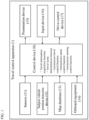
- FIG. 1 is a block diagram illustrating the configuration of a travel control apparatus 1 for a vehicle according to an embodiment of the present invention.
- the travel control apparatus 1 for a vehicle according to the present embodiment represents an embodiment for carrying out the travel control method for a vehicle according to the present invention.
- the travel control apparatus 1 for a vehicle according to the present embodiment includes sensors 11, a subject vehicle position detection device 12, a map database 13, onboard equipment 14, a presentation device 15, an input device 16, a drive control device 17, and a control device 18. These devices are connected to one another, for example, via a controller area network (CAN) or other onboard LAN for mutually exchanging information.
- CAN controller area network
- the sensors 11 detect a traveling state of a subject vehicle.
- the sensors 11 include, for example, a front camera that captures images ahead of the subject vehicle, a rear camera that captures images behind the subject vehicle, a front radar that detects obstacles ahead of the subject vehicle, a rear radar that detects obstacles behind the subject vehicle, side radars that detect obstacles existing on the right and left sides of the subject vehicle, a vehicle speed sensor that detects the vehicle speed of the subject vehicle, a sensor that detects the direction of rotation of the steering wheel, a sensor that detects the steering torque applied to the steering wheel, a touch sensor (capacitance sensor) that detects whether or not the driver holds the steering wheel, an onboard camera that captures images of the driver, etc.
- the sensors 11 may be represented by one of the above-described various sensors or may also be configured as a combination of two or more sensors. The detection results of the sensors 11 are output to the control device 18 at predetermined time intervals.
- the subject vehicle position detection device 12 is composed of a GPS unit, a gyro-sensor, a vehicle speed sensor, etc.
- the subject vehicle position detection device 12 detects radio waves transmitted from a plurality of communication satellites using the GPS unit to periodically acquire the positional information of a target vehicle (subject vehicle) and detects the current position of the target vehicle based on the acquired positional information of the target vehicle, angle variation information acquired from the gyro-sensor, and the vehicle speed acquired from the vehicle speed sensor.
- the positional information of the target vehicle detected by the subject vehicle position detection device 12 is output to the control device 18 at predetermined time intervals.
- the map database 13 is a memory that stores three-dimensional high-precision map information including positional information of various facilities and specific points and is accessible from the control device 18.
- the three-dimensional high-precision map information stored in the map database 13 is three-dimensional map information based on the road shape detected when traveling on an actual road using a vehicle for data acquisition, and in the three-dimensional map information, detailed and highly precise positional information items, such as a curved route and the size of the curve (e.g., curvature or radius of curvature), a merging point and a branching point of a road, a tollgate, a position at which the number of lanes is reduced, and a service area/parking area, are associated with the map information as the three-dimensional information.
- a curved route and the size of the curve e.g., curvature or radius of curvature
- a merging point and a branching point of a road e.g., curvature or radius of curvature
- the onboard equipment 14 includes various modules equipped in the vehicle and is operated by the driver's operation. Examples of such onboard equipment include a steering wheel, an accelerator pedal, a brake pedal, a navigation device, direction indicators, wipers, lights, a horn, and other specific switches. When the driver operates the onboard equipment 14, its operation information is output to the control device 18.
- the presentation device 15 is represented, for example, by devices such as a display of a navigation device, a display incorporated in a rearview mirror, a display incorporated in a meter unit, a head-up display projected on a windshield, a speaker of an audio device, and a seat device with embedded vibrating bodies.
- the presentation device 15 informs the driver of presentation information and lane change information, which will be described later, under the control by the control device 18.
- the input device 16 is, for example, a device such as a button switch or a touch panel disposed on a display screen with which the driver can input information by the manual operation or a microphone with which the driver can input information by the voice.
- the driver can operate the input device 16 thereby to input setting information in response to the presentation information which is presented by the presentation device 15.
- FIG. 2 is a front view illustrating a part of the input device 16 of the present embodiment and represents an example including a set of button switches arranged on a spoke part or the like of the steering wheel.
- the illustrated input device 16 includes button switches used when setting ON/OFF of an autonomous speed control function and an autonomous steering control function of the control device 18, and the button switches include a main switch (MAIN SW) 161, a resume/acceleration switch (RES +) 162, a set/coast switch (SET -) 163, a cancel switch (CANCEL) 164, an inter-vehicle distance adjustment switch (DISTANCE) 165, and a lane change assist switch (L/C) 166.
- MAIN SW main switch
- RES + resume/acceleration switch
- SET - set/coast switch
- CANCEL cancel switch
- DISTANCE inter-vehicle distance adjustment switch
- L/C lane change assist switch
- the main switch 161 is a switch for turning ON/OFF the power source of the system which achieves the autonomous speed control function and autonomous steering control function of the control device 18.
- the resume/acceleration switch 162 is a switch for turning OFF the operation of the autonomous speed control function and then resuming the autonomous speed control function at the set speed before the OFF state, for increasing the set speed, and/or for following a preceding vehicle to stop and then restarting.
- the set/coast switch 163 is a switch for starting the autonomous speed control function at the speed when traveling and/or lowering the set speed.
- the cancel switch 164 is a switch for turning OFF the autonomous speed control function.
- the inter-vehicle distance adjustment switch 165 is a switch for setting the inter-vehicle distance from a preceding vehicle and is, for example, a switch for selecting one from a plurality of stages of settings such as short distance/medium distance/long distance.
- the lane change assist switch 166 is a switch for instructing (accepting) the start of a lane change when the control device 18 confirms the start of the lane change with the driver.
- switches of the direction indicators or other onboard equipment 14 can also be used as the input device 16, and a configuration can be adopted in which the driver turns on the switch of the direction indicators in response to an inquiry from the control device 18 as to whether or not to perform a lane change in an automated or autonomous manner and inputs the acceptance or permission for the lane change.
- the setting information input with the input device 16 is output to the control device 18.
- the drive control device 17 controls travel of the subject vehicle. For example, when the subject vehicle travels at a constant set speed or travels to follow a preceding vehicle using the autonomous speed control function, the drive control device 17 controls the operation of the drive mechanism (including the operation of an internal-combustion engine in the case of an engine car or the operation of an electric motor for travel in the case of an electric car and also including the torque distribution for an internal-combustion engine and an electric motor for travel in the case of a hybrid car) and the brake operation for achieving the acceleration/deceleration and the traveling speed so that the speed of the subject vehicle becomes the set speed or, when there is a preceding vehicle, the inter-vehicle distance between the subject vehicle and the preceding vehicle becomes a constant distance.
- the drive mechanism including the operation of an internal-combustion engine in the case of an engine car or the operation of an electric motor for travel in the case of an electric car and also including the torque distribution for an internal-combustion engine and an electric motor for travel in the case of a hybrid car
- the autonomous steering control function when used to perform the lane keeping control for detecting lane markers of a lane in which the subject vehicle travels (also referred to as a subject vehicle lane, hereinafter) and controlling the traveling position of the subject vehicle in the road width direction so that the subject vehicle travels, for example, at the center in the subject vehicle lane, or when a lane change assist function, an overtaking assist function, or a route traveling assist function is used for the subject vehicle to perform automated lane change control such as overtaking of a preceding vehicle or a change of the traveling direction, or when a right or left turn assist function is used to perform travel control for turning right or left at an intersection or the like, the steering control of the subject vehicle is executed by controlling the operation of the steering actuator in addition to the operation of the drive mechanism and the brake operation for achieving the acceleration/deceleration and the traveling speed.
- the drive control device 17 controls the travel of the subject vehicle in accordance with instructions from the control device 18, which will be described below. Any of other known methods can also be used
- the control device 18 is composed of a read only memory (ROM) that stores programs for controlling the travel of the subject vehicle, a central processing unit (CPU) that executes the programs stored in the ROM, and a random access memory (RAM) that serves as an accessible storage device.
- ROM read only memory
- CPU central processing unit
- RAM random access memory
- MPU micro processing unit
- DSP digital signal processor
- ASIC application specific integrated circuit
- FPGA field programmable gate array
- the control device 18 executes the programs stored in the ROM using the CPU thereby to achieve a travel information acquisition function for acquiring information regarding a traveling state of the subject vehicle, a travel scene determination function for determining a travel scene of the subject vehicle, and an autonomous travel control function for autonomously controlling the traveling speed and/or steering of the subject vehicle (the autonomous travel control function includes an autonomous speed control function for autonomously controlling the traveling speed of the subject vehicle and an autonomous steering control function for autonomously controlling the steering of the subject vehicle).
- the travel information acquisition function of the control device 18 is a function used for acquiring the travel information regarding the traveling state of the subject vehicle.
- the control device 18 uses the travel information acquisition function to acquire as the travel information the external image information around the vehicle captured by the front camera and rear camera included in the sensors 11 and/or the detection results by the front radar, rear radar, and side radars included in the sensors 11.
- the control device 18 uses the travel information acquisition function to acquire as the travel information the vehicle speed information of the subject vehicle detected by the vehicle speed sensor included in the sensors 11 and/or the image information of the driver's face captured by the onboard camera included in the sensors 11.
- control device 18 uses the travel information acquisition function to acquire as the travel information the current positional information of the subject vehicle from the subject vehicle position detection device 12. Additionally or alternatively, the control device 18 uses the travel information acquisition function to acquire as the travel information the positional information of curved routes and the size of the curve (e.g., curvature or radius of curvature), merging points of roads, branching points, tollgates, positions at which the number of lanes decreases, service areas (SAs)/parking areas (PAs), etc. from the map database 13. In addition, the control device 18 uses the travel information acquisition function to acquire as the travel information the information on an operation of the onboard equipment 14 performed by the driver from the onboard equipment 14.
- SAs service areas
- PAs parking areas
- the travel scene determination function of the control device 18 is a function for referring to a table stored in the ROM of the control device 18 to determine a travel scene in which the subject vehicle is traveling.
- a travel scene suitable for changing lanes or overtaking and determination conditions thereof are stored for each travel scene.
- the control device 18 uses the travel scene determination function to refer to the table stored in the ROM and determine whether or not the travel scene of the subject vehicle is a travel scene suitable for, for example, changing lanes or overtaking.
- the control device 18 uses the travel scene determination function to determine whether or not the subject vehicle satisfies the above conditions, for example, based on the detection results by the front camera and/or the front radar included in the sensors 11, the vehicle speed of the subject vehicle detected by the vehicle speed sensor, and the positional information of the subject vehicle obtained by the subject vehicle position detection device 12 and, when the above conditions are satisfied, determines that the subject vehicle is in the "scene of catching up with the preceding vehicle.”
- the autonomous travel control function of the control device 18 is a function used for autonomously controlling the travel of the subject vehicle without depending on the driver's operation and includes an autonomous speed control function used for autonomously controlling the traveling speed of the subject vehicle and an autonomous steering control function used for autonomously controlling the steering of the subject vehicle.
- the autonomous speed control function and autonomous steering control function of the present embodiment will be described below.
- the autonomous speed control function is a function used, when detecting a preceding vehicle, for traveling to follow the preceding vehicle while performing the inter-vehicle distance control so as to maintain the inter-vehicle distance in accordance with the vehicle speed with an upper limit of the vehicle speed that is set by the driver.
- the autonomous speed control function is also a function used, when detecting no preceding vehicle, for performing constant speed traveling at a vehicle speed that is set by the driver.
- the former is also referred to as inter-vehicle distance control while the latter is also referred to as constant speed control.
- the autonomous speed control function may include a function used, when detecting the speed limit of a travel lane using the travel information acquisition function, for automatically adopting the speed of the speed limit sign as a set vehicle speed.
- the driver To activate the autonomous speed control function, the driver first operates the resume/acceleration switch 162 or set/coast switch 163 of the input device 16 illustrated in FIG. 2 to input a desired traveling speed. For example, when the set/coast switch 163 is pressed while the subject vehicle is traveling at 70 km/h, the current traveling speed is set without any modification, but if the speed desired by the driver is 80 km/h, the resume/acceleration switch 162 may be pressed a plurality of times to increase the set speed. On the contrary, if the speed desired by the driver is 60 km/h, the set/coast switch 163 may be pressed a plurality of times to decrease the set speed.
- the inter-vehicle distance desired by the driver may be selected, for example, from a plurality of stages of settings such as short distance/medium distance/long distance by operating the inter-vehicle distance adjustment switch 165 of the input device 16 illustrated in FIG. 2 .
- the drive control device 17 controls the operation of the drive mechanism such as the engine and the brake while feeding back the vehicle speed data obtained by the vehicle speed sensor so as to maintain the traveling speed which is set by the driver.
- This constant speed control is executed while using the sensors 11 such as the front radar, which detects an obstacle ahead of the subject vehicle, to detect that there is no preceding vehicle ahead of the subject vehicle in its travel lane.
- the drive control device 17 controls the operation of the drive mechanism such as the engine and the brake while feeding back the inter-vehicle distance data detected by the sensors 11 (front radar) so as to maintain the inter-vehicle distance, which is set by the driver, with an upper limit of the traveling speed that is set by the driver.
- This inter-vehicle distance control is executed while using the sensors 11 such as the front radar, which detects an obstacle ahead of the subject vehicle, to detect that there is a preceding vehicle ahead of the subject vehicle in its travel lane and detect the inter-vehicle distance (the preceding vehicle in this case is a vehicle located just ahead of the subject vehicle).
- the subject vehicle also stops following the preceding vehicle, and if the preceding vehicle starts within 30 seconds after the subject vehicle stops, the subject vehicle also starts traveling to follow the preceding vehicle again by the inter-vehicle distance control. If the subject vehicle stops for more than 30 seconds, the subject vehicle does not start in an automated or autonomous manner even when the preceding vehicle starts, and after the preceding vehicle starts, the subject vehicle starts traveling to follow the preceding vehicle again by the inter-vehicle distance control when the resume/acceleration switch 162 is pressed or the accelerator pedal is depressed.
- the autonomous speed control function of the present embodiment may include, in addition to the above-described constant speed control and inter-vehicle distance control, a curved route speed control function used for controlling the speed so as to be able to travel at a speed corresponding to the size of a curve (such as a curvature or radius of curvature of the curve) when traveling along a curved route.
- This curved route speed control function is a function for controlling the speed when traveling along a curved route only in the case in which the autonomous speed control function is operating.
- Whether or not there is a curved route ahead of the subject vehicle is detected in such a manner that, for example, when a destination is input to the navigation device and a route to the destination is set, a determination is made with reference to the map database 13 as to whether or not there is map data as a curved route on the route.
- the autonomous steering control function is a function used for controlling the operation of the steering actuator thereby to execute the steering control of the subject vehicle.
- This autonomous steering control function includes: a lane keeping function (lane width direction maintenance function) in which the steering is controlled so as to travel, for example, near the center of the lane to assist the driver's steering operation; a lane change assist function in which when the driver operates the blinker lever, the steering is controlled to assist the steering wheel operation necessary for changing lanes; an overtaking assist function in which when a vehicle slower than the set vehicle speed is detected ahead, a display is used for confirmation by the driver as to whether to perform an overtaking operation, and when the driver operates an acceptance switch, the steering is controlled to assist the overtaking operation; a route traveling assist function in which when the driver inputs the destination to the navigation device or the like and arrives at a lane change point required to travel along the route, a display is used for confirmation by the driver as to whether to perform a lane change, and when the driver operates an acceptance switch, the steering is controlled to assist the lane
- FIG. 3 is a block diagram illustrating a state transition of each function established in the control device 18.
- the system illustrated in the figure means an autonomous travel control system realized by the control device 18.
- the main switch 161 of FIG. 2 is turned ON from the system OFF state illustrated in the figure, the system comes to a standby state. From this standby state, the autonomous speed control is activated by turning ON the set/coast switch 163 or resume/acceleration switch 162 of FIG. 2 .
- This allows the above-described constant speed control or inter-vehicle distance control to be started, and the driver can drive the subject vehicle simply by operating the steering wheel without stepping on the accelerator or the brake.
- the mode transitions to the lane keeping mode of the autonomous steering control/hands-on mode.
- the condition (1) include, but are not limited to, a condition in which all of the following conditions are satisfied: lane markers on both sides of the subject vehicle are being detected; the driver is holding the steering wheel; the vehicle is traveling near the center of the lane; the blinkers are not operating; the windshield wiper is not operating at a high speed (HI); and when a high-precision map is provided, there is not a tollgate, an exit, a merging point, an intersection, or a point at which the number of lanes decreases, within about 200 m ahead.
- the hands-on mode refers to a mode in which the autonomous steering control does not operate unless the driver holds the steering wheel
- the hands-off mode refers to a mode in which the autonomous steering control operates even when the driver releases the steering wheel.
- the mode transitions to the lane keeping mode of the autonomous steering control/hands-off mode.
- the condition (2) include, but are not limited to, a condition in which all of the following conditions are satisfied: the subject vehicle is traveling on an automobile road; the vehicle is traveling on a road that is structurally separated from the oncoming lane; the vehicle is traveling on a road for which a high-precision map is prepared; the vehicle is traveling at a speed not higher than the speed limit; GPS signals are effective; the driver is holding the steering wheel; the driver is facing forward; there is not a tollgate, an exit, a merging point, an intersection, or a point at which the number of lanes decreases, within about 800 m ahead; there is not a sharp curve of 100R or less within about 500 m ahead; the vehicle is not traveling in a tunnel that exceeds 500 m from the tunnel entrance; and the accelerator pedal is not depressed.
- the mode transitions to the lane keeping mode of the autonomous steering control/hands-on mode.
- the condition (3) include, but are not limited to, a condition in which any of the following conditions is satisfied: the subject vehicle is traveling on a road other than an automobile road; the vehicle is traveling in a two-way traffic section; the vehicle is traveling on a road for which no high-precision map is prepared; the vehicle is traveling at a speed higher than the speed limit; GPS signals can no longer be received; the driver does not face forward within 5 seconds after a forward gaze alarm is activated; the driver monitor camera can no longer detect the driver; there is any of a tollgate, an exit, a merging point, an intersection, or a point at which the number of lanes decreases, within about 800 m ahead; when traveling at a vehicle speed of less than about 40 km/h, there is a sharp curve of 100R or less within about
- the autonomous steering control is stopped and transitions to the autonomous speed control.
- the condition (4) include, but are not limited to, a condition in which any of the following conditions is satisfied: lane markers on both sides of the subject vehicle are no longer detected for a certain period of time; the driver has operated the steering wheel (so-called an override operation/intervention operation); and the windshield wiper has operated at a high speed (HI).
- the condition (5) of FIG. 3 when the condition (5) of FIG. 3 is satisfied, the autonomous steering control and the autonomous speed control are stopped and transition to the standby state.
- Examples of the condition (5) include, but are not limited to, a condition in which any of the following conditions is satisfied: the driver has operated the brake; the driver has operated the cancel switch 164 of FIG. 2 ; one or more doors of the subject vehicle have opened; the driver's seat belt has been released; the seating sensor has detected that the driver is no longer on the driver's seat; the select lever has come to other than "D" or ""M”; the parking brake has been operated; the antiskid brake system of the vehicle has been turned OFF; the antiskid brake system has operated; the snow mode has been turned ON; the emergency brake has operated; the stop state continues for about 3 minutes after the vehicle has stopped due to the vehicle speed control; the front camera has detected poor visibility such as being unable to correctly recognize an object due to dirt, backlight, rain/fog, or the like; the front radar has detected shielding or radio disturbance; the front radar has detected an axis deviation; the side radar has detected shielding or radio disturbance; and the side radar has detected an axis deviation.
- the autonomous steering control is stopped and transitions to the autonomous speed control.
- the condition (6) include, but are not limited to, a condition in which any of the following conditions is satisfied: lane markers on both sides of the subject vehicle are no longer detected; the driver has operated the steering wheel (so-called an override operation/intervention operation); the driver has operated the blinkers; the windshield wiper has operated at a high speed (HI); the vehicle has come to a tollgate section when a high-precision map is prepared; and the front camera has detected poor visibility such as being unable to correctly recognize an object due to dirt, backlight, rain/fog, or the like.
- condition (7) of FIG. 3 when the condition (7) of FIG. 3 is satisfied, the autonomous steering control and the autonomous speed control are stopped and transition to the standby state.
- the condition (7) include, but are not limited to, a condition in which any of the following conditions is satisfied: the driver has operated the brake; the driver has operated the cancel switch 164 of FIG.
- condition (8) of FIG. 3 when the condition (8) of FIG. 3 is satisfied, the control transitions to the standby state.
- the condition (8) include, but are not limited to, a condition in which any of the following conditions is satisfied: the driver has operated the brake; the driver has operated the cancel switch 164 of FIG.
- the mode transitions to a lane change mode of the autonomous steering control/hands-on mode.
- the condition (9) include, but are not limited to, a condition in which any of the following conditions is satisfied: when the system has proposed a lane change, the driver has pressed the lane change assist switch 166 of FIG. 2 ; and the driver has operated the blinkers.
- the mode transitions to the lane keeping mode of the autonomous steering control/hands-on mode.
- the condition (10) include, but are not limited to, a condition in which any of the following conditions is satisfied: the speed limit has been exceeded before the start of a lane change performance (abbreviated as LCP, hereinafter); the driver has stepped on the accelerator pedal while holding the steering wheel before the start of the LCP; the LCP can no longer be started within 10 seconds after pressing the lane change assist switch 166 during the proposal of a lane change when there is a slow car ahead; the LCP can no longer be started and the vehicle has come too close to the branching point after pressing the lane change assist switch 166 during the proposal of a lane change to travel along the route; a lane change maneuver (abbreviated as LCM, hereinafter) can no longer be started within 5 seconds after the LCP has operated; the vehicle speed limit has been exceeded before the start of a lane change performance (abbreviated as LCP, hereinafter); the driver has stepped on
- the system is turned OFF when the main switch 161 is turned OFF in any of the autonomous steering control/hands-off mode, the autonomous steering control/hands-on mode, the autonomous speed control, and the standby state.
- the autonomous steering control (hands-on mode or hands-off mode) in the above-described state transition, when the condition that the driver has operated the steering wheel in the condition (4) or (6) is satisfied, the autonomous steering control is released (canceled) and transitions to the autonomous speed control by the driver's steering wheel operation.
- the detection as to whether or not the driver has operated the steering wheel is performed using a torque sensor that detects the driver's steering torque applied to the steering wheel, and when the detected steering torque exceeds a cancellation threshold that is preliminarily set, a determination is made that the driver has operated the steering wheel.
- the driver's intervention operation for canceling the autonomous steering control and transitioning to the driver's manual operation is not limited to the rotation operation of the steering wheel and may also be an operation of an intervention button or the like.
- a plurality of cancellation thresholds is set corresponding to respective travel scenes. That is, the cancellation threshold is set to a relatively small value in the case of a travel scene in which transition from the autonomous steering control to the driver's manual operation is desired, while the cancellation threshold is set to a relatively large value in the case of a travel scene in which the transition is not desired.
- FIG. 4A is a plan view illustrating a main road 21 and an exit road 22 of an automobile road 2 having three lanes on each side, and it is assumed that the main road 21 represents an area for which three-dimensional high-precision map information is prepared while the exit road 22 and subsequent ones represent an area for which three-dimensional high-precision map information is not prepared.
- FIG. 5 is a diagram illustrating the cancellation threshold for each travel scene with respect to the steering torque stored in the control device 18.
- the standard cancellation threshold refers to a minimum value of the steering torque of the steering wheel operated by the driver, and this value is required to cancel the autonomous steering control and transition to the driver's manual operation.
- the autonomous steering control is canceled and transitions to the driver's manual operation.
- FIG. 4B is a plan view illustrating an automobile road including a curved route, and the subject vehicle V is about to turn right along a curved route 23.
- the standard cancellation threshold is used for traveling along a straight route
- the driver may want to drive with his/her own driving feeling, and it can therefore be said that such a scene is a travel scene in which it is desired to transition from the autonomous steering control to the driver's manual operation as soon as possible.
- a second cancellation threshold smaller than the standard cancellation threshold is set for a second travel scene of traveling along the curved route 23.
- the second cancellation threshold is set to a value larger than the first cancellation threshold.
- a third cancellation threshold in the case of S2 in which the turning direction of the subject vehicle V and the turning direction of the steering wheel are opposite directions is set as a relatively larger value than the second cancellation threshold in a case of S1 in which the turning direction of the subject vehicle V and the turning direction of the steering wheel are the identical direction.
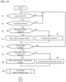
- FIGS. 6A and 6B are flowcharts illustrating the travel control process according to the present embodiment.
- the control device 18 executes the travel control process, which will be described below, at predetermined time intervals. The following description will be made on the assumption that the control device 18 uses the autonomous travel control function to execute the autonomous speed control and the autonomous steering control and the subject vehicle travels near an exit of an automobile road or along a curved route while the lane keeping control for controlling the traveling position of the subject vehicle in the width direction is performed so that the subject vehicle travels in the lane at a speed that is set by the driver.
- step S1 of FIG. 6A a determination is made as to whether or not the main switch 161 of the control device 18 is ON, and when the main switch 161 is OFF, step S1 is repeated until the main switch 161 is turned ON.
- the process proceeds to step S2, in which a determination is made as to whether or not the traveling speed is set by the driver.
- step S2 the process returns to step S1, from which steps S1 and S2 are repeated until the traveling speed is set.
- the setting of the traveling speed is performed by the driver operating the resume/acceleration switch 162 or set/coast switch 163 of the input device 16 illustrated in FIG. 2 to input a desired traveling speed.
- step S3 the front radar (of the sensors 11) which detects an obstacle ahead of the subject vehicle is used to detect whether or not there is a preceding vehicle ahead of the subject vehicle in its travel lane, and when there is a preceding vehicle, the process proceeds to step S4, in which the inter-vehicle distance control is executed, while when there is no preceding vehicle, the process proceeds to step S5, in which the constant speed control is executed.
- step S3 the front radar (of the sensors 11) which detects an obstacle ahead of the subject vehicle is used to detect whether or not there is a preceding vehicle ahead of the subject vehicle in its travel lane, and when there is a preceding vehicle, the process proceeds to step S4, in which the inter-vehicle distance control is executed, while when there is no preceding vehicle, the process proceeds to step S5, in which the constant speed control is executed.
- step S6 a determination is made in step S6 as to whether or not the above-described condition (1) for transitioning to the lane keeping mode of the autonomous steering control/hands-on mode is satisfied.
- the process proceeds to step S7, while when the condition (1) is not satisfied, the process returns to step S1.
- step S7 the front radar (of the sensors 11) which detects an obstacle ahead of the subject vehicle is used to detect whether or not there is a preceding vehicle ahead of the subject vehicle in its travel lane, and when there is a preceding vehicle, the process proceeds to step S8, in which the inter-vehicle distance control/lane keeping mode is executed, while when there is no preceding vehicle, the process proceeds to step S9, in which the constant speed control/lane keeping mode is executed. In this state, the execution process for the lane change assist function and/or overtaking assist function of step S10 is performed.
- step S8 During the execution of the inter-vehicle distance control/lane keeping mode in step S8 or the constant speed control/lane keeping mode in step S9, a determination is made in the subsequent step S11 of FIG. 6B as to whether or not the above-described condition (2) for transitioning to the autonomous steering control/hands-off mode is satisfied.
- the process proceeds to step S12, while when the condition (2) is not satisfied, the process proceeds to step S15.
- the front radar (of the sensors 11) which detects an obstacle ahead of the subject vehicle is used to detect whether or not there is a preceding vehicle ahead of the subject vehicle in its travel lane.
- step S13 the inter-vehicle distance control/lane keeping mode/hands-off is executed
- step S14 the constant speed control/lane keeping mode/hands-off is executed.
- step S15 a travel scene such as an exit, tollgate, or curved route of an automobile road existing ahead of the subject vehicle on its route is detected from the map database 13, the cancellation threshold corresponding to the detected travel scene is extracted, and the value is set to the cancellation threshold.
- the cancellation threshold is set to the first cancellation threshold.
- the cancellation threshold is set to the second cancellation threshold, while when there is a curved route and the turning direction of the subject vehicle and the turning direction of the steering wheel are opposite directions, the cancellation threshold is set to the third cancellation threshold.
- step S16 a determination is made as to whether or not the steering torque detected by the torque sensor exceeds the set cancellation threshold, and when the steering torque exceeds the set cancellation threshold, the process proceeds to step S23, in which the autonomous steering control is canceled, and then the process returns to step S1.
- step S17 the front radar (of the sensors 11) which detects an obstacle ahead of the subject vehicle is used to detect whether or not there is a preceding vehicle ahead of the subject vehicle in its travel lane.
- step S18 in which the inter-vehicle distance control/lane keeping mode/curved route speed control is executed
- step S19 in which the constant speed control/lane keeping mode/curved route speed control is executed.
- step S20 the front radar (of the sensors 11) which detects an obstacle ahead of the subject vehicle is used to detect whether or not there is a preceding vehicle ahead of the subject vehicle in its travel lane.
- step S21 a determination is made as in step S6 as to whether or not the condition (1) for transitioning to the lane keeping mode of the autonomous steering control/hands-on mode is satisfied, and when the condition (1) is satisfied, the process proceeds to step S22.
- step S22 a determination is made as in step S11 as to whether or not the condition (2) for transitioning to the autonomous steering control/hands-off mode is satisfied, and when the condition (2) is satisfied, the process returns to step S12, from which the subsequent processes are continued.
- step S1 the condition or (2) is satisfied
- a plurality of cancellation thresholds corresponding to respective travel scenes is set. That is, the cancellation threshold is set to a relatively small value in the case of a travel scene in which transition from the autonomous steering control to the driver's manual operation is desired, while the cancellation threshold is set to a relatively large value in the case of a travel scene in which the transition is not desired, and it is therefore possible to respond to the request for transition from the autonomous steering control to the manual operation in accordance with the travel scene of the vehicle.
- a first travel scene of traveling from within an area subjected to the autonomous steering control to outside the area a first cancellation threshold smaller than the standard cancellation threshold is set, and it is therefore possible to respond to a travel scene in which it is desired to transition from the autonomous steering control to the driver's manual operation as soon as possible.
- the travel scene includes a second travel scene of traveling along a curved route, and a second cancellation threshold smaller than the standard cancellation threshold is set for the second travel scene; therefore, it is possible to respond to a travel scene in which it is desired to transition from the autonomous steering control to the driver's manual operation as soon as possible.
- the second cancellation threshold is set to a value larger than the first cancellation threshold.
- the cancellation threshold in the case of a travel scene in which the turning direction of the vehicle and the turning direction of the steering wheel operated by the driver are opposite directions is set as a larger value than that in the case of a travel scene in which the turning direction of the vehicle and the turning direction of the steering wheel operated by the driver are the identical direction.
Landscapes
- Engineering & Computer Science (AREA)
- Transportation (AREA)
- Mechanical Engineering (AREA)
- Chemical & Material Sciences (AREA)
- Combustion & Propulsion (AREA)
- General Physics & Mathematics (AREA)
- Physics & Mathematics (AREA)
- Multimedia (AREA)
- Theoretical Computer Science (AREA)
- Automation & Control Theory (AREA)
- Human Computer Interaction (AREA)
- Control Of Driving Devices And Active Controlling Of Vehicle (AREA)
- Steering Control In Accordance With Driving Conditions (AREA)
- Traffic Control Systems (AREA)
Description
- The present invention relates to a travel control method and a travel control apparatus for a vehicle that include autonomous travel control.
- A lane keeping assist device is known, which assists the steering so as to travel in a travel lane and stops the assist when the driver's steering amount not less than a cancellation determination threshold is detected. In this device, when the driver's steering holding force for the steering wheel (this force represents whether the driver grasps the steering wheel firmly or lightly) is large, the cancellation determination threshold is changed to a large value thereby to improve both easiness of override and a system working factor (Patent Document 1).
- According to the above prior art, however, the cancellation determination threshold is changed depending only on the magnitude of the driver's steering holding force for the steering wheel, and the same control is therefore performed regardless of the travel scene, such as a scene in which transition is desired from the autonomous steering control by the system to the driver's manual operation or a scene in which the transition is not desired. Thus, there is a problem in that it is not possible to respond to the request for transition in accordance with the travel scene of the vehicle.
-
EP 0 640 903 A1 relates to a lane keeping assistance system, wherein a torque and a haptic feedback is provided to the steering wheel depending on a deviation of the vehicle from a center of the lane. When the driver releases the steering wheel, the vehicle returns to the center of the lane. -
US 2012/283910 A1 relates to lane keeping assist for a vehicle, wherein automatic control may be overridden by the driver. When a difference between a measured steering torque and a predicted steering torque exceeds a predetermined threshold and a difference between a measured steering angle and a predicted steering angle exceeds a predetermined threshold, steering control is yielded to the driver.US 2012/283910 A1 dislcoses in particular a travel control method for a vehicle, including autonomous steering control for autonomously controlling steering of the vehicle, the travel control method comprising:
detecting a travel scene of the vehicle (V) during execution of the autonomous steering control. - A problem to be solved by the present invention is to provide a travel control method and a travel control apparatus for a vehicle that are able to respond to the request for transition from the autonomous steering control to the manual operation in accordance with the travel scene of the vehicle.
- The present invention solves the above problem through the features of the independent claims. The dependent claims describe advantageous embodiments.
- According to the present invention, a plurality of cancellation thresholds is set corresponding to respective travel scenes and it is therefore possible to respond to the request for transition from the autonomous steering control to the manual operation in accordance with the travel scene of the vehicle.
-
-
FIG. 1 is a block diagram illustrating an embodiment of the travel control apparatus for a vehicle according to the present invention. -
FIG. 2 is a front view illustrating a part of the input device ofFIG. 1 . -
FIG. 3 is a block diagram illustrating a state transition of the control device ofFIG. 1 . -
FIG. 4A is a plan view illustrating an example of a travel scene (exit of an automobile road). -
FIG. 4B is a plan view illustrating another example of a travel scene (curved route). -
FIG. 5 is a diagram illustrating a cancellation threshold for each travel scene with respect to the steering torque stored in the control device ofFIG. 1 . -
FIG. 6A is a flowchart (part 1) illustrating a travel control process of the travel control apparatus for a vehicle according to the present invention. -
FIG. 6B is a flowchart (part 2) illustrating the travel control process of the travel control apparatus for a vehicle according to the present invention. -
FIG. 1 is a block diagram illustrating the configuration of atravel control apparatus 1 for a vehicle according to an embodiment of the present invention. Thetravel control apparatus 1 for a vehicle according to the present embodiment represents an embodiment for carrying out the travel control method for a vehicle according to the present invention. As illustrated inFIG. 1 , thetravel control apparatus 1 for a vehicle according to the present embodiment includessensors 11, a subject vehicleposition detection device 12, amap database 13,onboard equipment 14, apresentation device 15, aninput device 16, adrive control device 17, and acontrol device 18. These devices are connected to one another, for example, via a controller area network (CAN) or other onboard LAN for mutually exchanging information. - The
sensors 11 detect a traveling state of a subject vehicle. Examples of thesensors 11 include, for example, a front camera that captures images ahead of the subject vehicle, a rear camera that captures images behind the subject vehicle, a front radar that detects obstacles ahead of the subject vehicle, a rear radar that detects obstacles behind the subject vehicle, side radars that detect obstacles existing on the right and left sides of the subject vehicle, a vehicle speed sensor that detects the vehicle speed of the subject vehicle, a sensor that detects the direction of rotation of the steering wheel, a sensor that detects the steering torque applied to the steering wheel, a touch sensor (capacitance sensor) that detects whether or not the driver holds the steering wheel, an onboard camera that captures images of the driver, etc. Thesensors 11 may be represented by one of the above-described various sensors or may also be configured as a combination of two or more sensors. The detection results of thesensors 11 are output to thecontrol device 18 at predetermined time intervals. - The subject vehicle
position detection device 12 is composed of a GPS unit, a gyro-sensor, a vehicle speed sensor, etc. The subject vehicleposition detection device 12 detects radio waves transmitted from a plurality of communication satellites using the GPS unit to periodically acquire the positional information of a target vehicle (subject vehicle) and detects the current position of the target vehicle based on the acquired positional information of the target vehicle, angle variation information acquired from the gyro-sensor, and the vehicle speed acquired from the vehicle speed sensor. The positional information of the target vehicle detected by the subject vehicleposition detection device 12 is output to thecontrol device 18 at predetermined time intervals. - The
map database 13 is a memory that stores three-dimensional high-precision map information including positional information of various facilities and specific points and is accessible from thecontrol device 18. The three-dimensional high-precision map information stored in themap database 13 is three-dimensional map information based on the road shape detected when traveling on an actual road using a vehicle for data acquisition, and in the three-dimensional map information, detailed and highly precise positional information items, such as a curved route and the size of the curve (e.g., curvature or radius of curvature), a merging point and a branching point of a road, a tollgate, a position at which the number of lanes is reduced, and a service area/parking area, are associated with the map information as the three-dimensional information. - The
onboard equipment 14 includes various modules equipped in the vehicle and is operated by the driver's operation. Examples of such onboard equipment include a steering wheel, an accelerator pedal, a brake pedal, a navigation device, direction indicators, wipers, lights, a horn, and other specific switches. When the driver operates theonboard equipment 14, its operation information is output to thecontrol device 18. - The
presentation device 15 is represented, for example, by devices such as a display of a navigation device, a display incorporated in a rearview mirror, a display incorporated in a meter unit, a head-up display projected on a windshield, a speaker of an audio device, and a seat device with embedded vibrating bodies. Thepresentation device 15 informs the driver of presentation information and lane change information, which will be described later, under the control by thecontrol device 18. - The
input device 16 is, for example, a device such as a button switch or a touch panel disposed on a display screen with which the driver can input information by the manual operation or a microphone with which the driver can input information by the voice. In the present embodiment, the driver can operate theinput device 16 thereby to input setting information in response to the presentation information which is presented by thepresentation device 15.FIG. 2 is a front view illustrating a part of theinput device 16 of the present embodiment and represents an example including a set of button switches arranged on a spoke part or the like of the steering wheel. The illustratedinput device 16 includes button switches used when setting ON/OFF of an autonomous speed control function and an autonomous steering control function of thecontrol device 18, and the button switches include a main switch (MAIN SW) 161, a resume/acceleration switch (RES +) 162, a set/coast switch (SET -) 163, a cancel switch (CANCEL) 164, an inter-vehicle distance adjustment switch (DISTANCE) 165, and a lane change assist switch (L/C) 166. - The
main switch 161 is a switch for turning ON/OFF the power source of the system which achieves the autonomous speed control function and autonomous steering control function of thecontrol device 18. The resume/acceleration switch 162 is a switch for turning OFF the operation of the autonomous speed control function and then resuming the autonomous speed control function at the set speed before the OFF state, for increasing the set speed, and/or for following a preceding vehicle to stop and then restarting. The set/coast switch 163 is a switch for starting the autonomous speed control function at the speed when traveling and/or lowering the set speed. Thecancel switch 164 is a switch for turning OFF the autonomous speed control function. The inter-vehicledistance adjustment switch 165 is a switch for setting the inter-vehicle distance from a preceding vehicle and is, for example, a switch for selecting one from a plurality of stages of settings such as short distance/medium distance/long distance. The lanechange assist switch 166 is a switch for instructing (accepting) the start of a lane change when thecontrol device 18 confirms the start of the lane change with the driver. - Additionally or alternatively to the set of button switches illustrated in
FIG. 2 , switches of the direction indicators or otheronboard equipment 14 can also be used as theinput device 16, and a configuration can be adopted in which the driver turns on the switch of the direction indicators in response to an inquiry from thecontrol device 18 as to whether or not to perform a lane change in an automated or autonomous manner and inputs the acceptance or permission for the lane change. The setting information input with theinput device 16 is output to thecontrol device 18. - The
drive control device 17 controls travel of the subject vehicle. For example, when the subject vehicle travels at a constant set speed or travels to follow a preceding vehicle using the autonomous speed control function, thedrive control device 17 controls the operation of the drive mechanism (including the operation of an internal-combustion engine in the case of an engine car or the operation of an electric motor for travel in the case of an electric car and also including the torque distribution for an internal-combustion engine and an electric motor for travel in the case of a hybrid car) and the brake operation for achieving the acceleration/deceleration and the traveling speed so that the speed of the subject vehicle becomes the set speed or, when there is a preceding vehicle, the inter-vehicle distance between the subject vehicle and the preceding vehicle becomes a constant distance. Additionally or alternatively, when the autonomous steering control function is used to perform the lane keeping control for detecting lane markers of a lane in which the subject vehicle travels (also referred to as a subject vehicle lane, hereinafter) and controlling the traveling position of the subject vehicle in the road width direction so that the subject vehicle travels, for example, at the center in the subject vehicle lane, or when a lane change assist function, an overtaking assist function, or a route traveling assist function is used for the subject vehicle to perform automated lane change control such as overtaking of a preceding vehicle or a change of the traveling direction, or when a right or left turn assist function is used to perform travel control for turning right or left at an intersection or the like, the steering control of the subject vehicle is executed by controlling the operation of the steering actuator in addition to the operation of the drive mechanism and the brake operation for achieving the acceleration/deceleration and the traveling speed. Thedrive control device 17 controls the travel of the subject vehicle in accordance with instructions from thecontrol device 18, which will be described below. Any of other known methods can also be used as the travel control method executed by thedrive control device 17. - The
control device 18 is composed of a read only memory (ROM) that stores programs for controlling the travel of the subject vehicle, a central processing unit (CPU) that executes the programs stored in the ROM, and a random access memory (RAM) that serves as an accessible storage device. As substitute for or in addition to the CPU, a micro processing unit (MPU), a digital signal processor (DSP), an application specific integrated circuit (ASIC), a field programmable gate array (FPGA), or the like can be used as the operation circuit. - The
control device 18 executes the programs stored in the ROM using the CPU thereby to achieve a travel information acquisition function for acquiring information regarding a traveling state of the subject vehicle, a travel scene determination function for determining a travel scene of the subject vehicle, and an autonomous travel control function for autonomously controlling the traveling speed and/or steering of the subject vehicle (the autonomous travel control function includes an autonomous speed control function for autonomously controlling the traveling speed of the subject vehicle and an autonomous steering control function for autonomously controlling the steering of the subject vehicle). - The travel information acquisition function of the
control device 18 is a function used for acquiring the travel information regarding the traveling state of the subject vehicle. For example, thecontrol device 18 uses the travel information acquisition function to acquire as the travel information the external image information around the vehicle captured by the front camera and rear camera included in thesensors 11 and/or the detection results by the front radar, rear radar, and side radars included in thesensors 11. Additionally or alternatively, thecontrol device 18 uses the travel information acquisition function to acquire as the travel information the vehicle speed information of the subject vehicle detected by the vehicle speed sensor included in thesensors 11 and/or the image information of the driver's face captured by the onboard camera included in thesensors 11. - Additionally or alternatively, the
control device 18 uses the travel information acquisition function to acquire as the travel information the current positional information of the subject vehicle from the subject vehicleposition detection device 12. Additionally or alternatively, thecontrol device 18 uses the travel information acquisition function to acquire as the travel information the positional information of curved routes and the size of the curve (e.g., curvature or radius of curvature), merging points of roads, branching points, tollgates, positions at which the number of lanes decreases, service areas (SAs)/parking areas (PAs), etc. from themap database 13. In addition, thecontrol device 18 uses the travel information acquisition function to acquire as the travel information the information on an operation of theonboard equipment 14 performed by the driver from theonboard equipment 14. - The travel scene determination function of the
control device 18 is a function for referring to a table stored in the ROM of thecontrol device 18 to determine a travel scene in which the subject vehicle is traveling. In the table stored in the ROM of thecontrol device 18, for example, a travel scene suitable for changing lanes or overtaking and determination conditions thereof are stored for each travel scene. Thecontrol device 18 uses the travel scene determination function to refer to the table stored in the ROM and determine whether or not the travel scene of the subject vehicle is a travel scene suitable for, for example, changing lanes or overtaking. - It is assumed, for example, that four conditions of "there is a preceding vehicle ahead," "the vehicle speed of the preceding vehicle < the set vehicle speed of the subject vehicle," "the arrival at the preceding vehicle is within a predetermined time," and "the direction of lane change is not a lane change prohibition condition" are set as the determination conditions for a "scene of catching up with the preceding vehicle." In this case, the
control device 18 uses the travel scene determination function to determine whether or not the subject vehicle satisfies the above conditions, for example, based on the detection results by the front camera and/or the front radar included in thesensors 11, the vehicle speed of the subject vehicle detected by the vehicle speed sensor, and the positional information of the subject vehicle obtained by the subject vehicleposition detection device 12 and, when the above conditions are satisfied, determines that the subject vehicle is in the "scene of catching up with the preceding vehicle." - The autonomous travel control function of the
control device 18 is a function used for autonomously controlling the travel of the subject vehicle without depending on the driver's operation and includes an autonomous speed control function used for autonomously controlling the traveling speed of the subject vehicle and an autonomous steering control function used for autonomously controlling the steering of the subject vehicle. The autonomous speed control function and autonomous steering control function of the present embodiment will be described below. - The autonomous speed control function is a function used, when detecting a preceding vehicle, for traveling to follow the preceding vehicle while performing the inter-vehicle distance control so as to maintain the inter-vehicle distance in accordance with the vehicle speed with an upper limit of the vehicle speed that is set by the driver. The autonomous speed control function is also a function used, when detecting no preceding vehicle, for performing constant speed traveling at a vehicle speed that is set by the driver. The former is also referred to as inter-vehicle distance control while the latter is also referred to as constant speed control. The autonomous speed control function may include a function used, when detecting the speed limit of a travel lane using the travel information acquisition function, for automatically adopting the speed of the speed limit sign as a set vehicle speed.
- To activate the autonomous speed control function, the driver first operates the resume/
acceleration switch 162 or set/coast switch 163 of theinput device 16 illustrated inFIG. 2 to input a desired traveling speed. For example, when the set/coast switch 163 is pressed while the subject vehicle is traveling at 70 km/h, the current traveling speed is set without any modification, but if the speed desired by the driver is 80 km/h, the resume/acceleration switch 162 may be pressed a plurality of times to increase the set speed. On the contrary, if the speed desired by the driver is 60 km/h, the set/coast switch 163 may be pressed a plurality of times to decrease the set speed. The inter-vehicle distance desired by the driver may be selected, for example, from a plurality of stages of settings such as short distance/medium distance/long distance by operating the inter-vehicledistance adjustment switch 165 of theinput device 16 illustrated inFIG. 2 . - In the constant speed control, the
drive control device 17 controls the operation of the drive mechanism such as the engine and the brake while feeding back the vehicle speed data obtained by the vehicle speed sensor so as to maintain the traveling speed which is set by the driver. This constant speed control is executed while using thesensors 11 such as the front radar, which detects an obstacle ahead of the subject vehicle, to detect that there is no preceding vehicle ahead of the subject vehicle in its travel lane. - In the inter-vehicle distance control, the
drive control device 17 controls the operation of the drive mechanism such as the engine and the brake while feeding back the inter-vehicle distance data detected by the sensors 11 (front radar) so as to maintain the inter-vehicle distance, which is set by the driver, with an upper limit of the traveling speed that is set by the driver. This inter-vehicle distance control is executed while using thesensors 11 such as the front radar, which detects an obstacle ahead of the subject vehicle, to detect that there is a preceding vehicle ahead of the subject vehicle in its travel lane and detect the inter-vehicle distance (the preceding vehicle in this case is a vehicle located just ahead of the subject vehicle). If the preceding vehicle stops while the subject vehicle is traveling under the inter-vehicle distance control, the subject vehicle also stops following the preceding vehicle, and if the preceding vehicle starts within 30 seconds after the subject vehicle stops, the subject vehicle also starts traveling to follow the preceding vehicle again by the inter-vehicle distance control. If the subject vehicle stops for more than 30 seconds, the subject vehicle does not start in an automated or autonomous manner even when the preceding vehicle starts, and after the preceding vehicle starts, the subject vehicle starts traveling to follow the preceding vehicle again by the inter-vehicle distance control when the resume/acceleration switch 162 is pressed or the accelerator pedal is depressed. - The autonomous speed control function of the present embodiment may include, in addition to the above-described constant speed control and inter-vehicle distance control, a curved route speed control function used for controlling the speed so as to be able to travel at a speed corresponding to the size of a curve (such as a curvature or radius of curvature of the curve) when traveling along a curved route. This curved route speed control function is a function for controlling the speed when traveling along a curved route only in the case in which the autonomous speed control function is operating. Whether or not there is a curved route ahead of the subject vehicle is detected in such a manner that, for example, when a destination is input to the navigation device and a route to the destination is set, a determination is made with reference to the
map database 13 as to whether or not there is map data as a curved route on the route. - The autonomous steering control function is a function used for controlling the operation of the steering actuator thereby to execute the steering control of the subject vehicle. This autonomous steering control function includes: a lane keeping function (lane width direction maintenance function) in which the steering is controlled so as to travel, for example, near the center of the lane to assist the driver's steering operation; a lane change assist function in which when the driver operates the blinker lever, the steering is controlled to assist the steering wheel operation necessary for changing lanes; an overtaking assist function in which when a vehicle slower than the set vehicle speed is detected ahead, a display is used for confirmation by the driver as to whether to perform an overtaking operation, and when the driver operates an acceptance switch, the steering is controlled to assist the overtaking operation; a route traveling assist function in which when the driver inputs the destination to the navigation device or the like and arrives at a lane change point required to travel along the route, a display is used for confirmation by the driver as to whether to perform a lane change, and when the driver operates an acceptance switch, the steering is controlled to assist the lane change; and other functions.
-
FIG. 3 is a block diagram illustrating a state transition of each function established in thecontrol device 18. The system illustrated in the figure means an autonomous travel control system realized by thecontrol device 18. When themain switch 161 ofFIG. 2 is turned ON from the system OFF state illustrated in the figure, the system comes to a standby state. From this standby state, the autonomous speed control is activated by turning ON the set/coast switch 163 or resume/acceleration switch 162 ofFIG. 2 . This allows the above-described constant speed control or inter-vehicle distance control to be started, and the driver can drive the subject vehicle simply by operating the steering wheel without stepping on the accelerator or the brake. - During the execution of the autonomous speed control, when the condition (1) of
FIG. 3 is satisfied, the mode transitions to the lane keeping mode of the autonomous steering control/hands-on mode. Examples of the condition (1) include, but are not limited to, a condition in which all of the following conditions are satisfied: lane markers on both sides of the subject vehicle are being detected; the driver is holding the steering wheel; the vehicle is traveling near the center of the lane; the blinkers are not operating; the windshield wiper is not operating at a high speed (HI); and when a high-precision map is provided, there is not a tollgate, an exit, a merging point, an intersection, or a point at which the number of lanes decreases, within about 200 m ahead. The hands-on mode refers to a mode in which the autonomous steering control does not operate unless the driver holds the steering wheel, while the hands-off mode refers to a mode in which the autonomous steering control operates even when the driver releases the steering wheel. - During the execution of the lane keeping mode of the autonomous steering control/hands-on mode, when the condition (2) of
FIG. 3 is satisfied, the mode transitions to the lane keeping mode of the autonomous steering control/hands-off mode. Examples of the condition (2) include, but are not limited to, a condition in which all of the following conditions are satisfied: the subject vehicle is traveling on an automobile road; the vehicle is traveling on a road that is structurally separated from the oncoming lane; the vehicle is traveling on a road for which a high-precision map is prepared; the vehicle is traveling at a speed not higher than the speed limit; GPS signals are effective; the driver is holding the steering wheel; the driver is facing forward; there is not a tollgate, an exit, a merging point, an intersection, or a point at which the number of lanes decreases, within about 800 m ahead; there is not a sharp curve of 100R or less within about 500 m ahead; the vehicle is not traveling in a tunnel that exceeds 500 m from the tunnel entrance; and the accelerator pedal is not depressed. - On the contrary, during the execution of the lane keeping mode of the autonomous steering control/hands-off mode, when the condition (3) of
FIG. 3 is satisfied, the mode transitions to the lane keeping mode of the autonomous steering control/hands-on mode. Examples of the condition (3) include, but are not limited to, a condition in which any of the following conditions is satisfied: the subject vehicle is traveling on a road other than an automobile road; the vehicle is traveling in a two-way traffic section; the vehicle is traveling on a road for which no high-precision map is prepared; the vehicle is traveling at a speed higher than the speed limit; GPS signals can no longer be received; the driver does not face forward within 5 seconds after a forward gaze alarm is activated; the driver monitor camera can no longer detect the driver; there is any of a tollgate, an exit, a merging point, an intersection, or a point at which the number of lanes decreases, within about 800 m ahead; when traveling at a vehicle speed of less than about 40 km/h, there is a sharp curve of 100R or less within about 200 m ahead; when traveling at a vehicle speed of about 40 km/h or more, there is a sharp curve of 170R or less within about 200 m ahead; the vehicle is traveling in a tunnel that exceeds 500 m from the tunnel entrance; the driver has stepped on the accelerator pedal while holding the steering wheel; and an approaching alarm has operated. - During the execution of the lane keeping mode of the autonomous steering control/hands-off mode, when the condition (4) of
FIG. 3 is satisfied, the autonomous steering control is stopped and transitions to the autonomous speed control. Examples of the condition (4) include, but are not limited to, a condition in which any of the following conditions is satisfied: lane markers on both sides of the subject vehicle are no longer detected for a certain period of time; the driver has operated the steering wheel (so-called an override operation/intervention operation); and the windshield wiper has operated at a high speed (HI). During the execution of the lane keeping mode of the autonomous steering control/hands-off mode, when the condition (5) ofFIG. 3 is satisfied, the autonomous steering control and the autonomous speed control are stopped and transition to the standby state. Examples of the condition (5) include, but are not limited to, a condition in which any of the following conditions is satisfied: the driver has operated the brake; the driver has operated the cancelswitch 164 ofFIG. 2 ; one or more doors of the subject vehicle have opened; the driver's seat belt has been released; the seating sensor has detected that the driver is no longer on the driver's seat; the select lever has come to other than "D" or ""M"; the parking brake has been operated; the antiskid brake system of the vehicle has been turned OFF; the antiskid brake system has operated; the snow mode has been turned ON; the emergency brake has operated; the stop state continues for about 3 minutes after the vehicle has stopped due to the vehicle speed control; the front camera has detected poor visibility such as being unable to correctly recognize an object due to dirt, backlight, rain/fog, or the like; the front radar has detected shielding or radio disturbance; the front radar has detected an axis deviation; the side radar has detected shielding or radio disturbance; and the side radar has detected an axis deviation. - During the execution of the autonomous steering control/hands-on mode, when the condition (6) of
FIG. 3 is satisfied, the autonomous steering control is stopped and transitions to the autonomous speed control. Examples of the condition (6) include, but are not limited to, a condition in which any of the following conditions is satisfied: lane markers on both sides of the subject vehicle are no longer detected; the driver has operated the steering wheel (so-called an override operation/intervention operation); the driver has operated the blinkers; the windshield wiper has operated at a high speed (HI); the vehicle has come to a tollgate section when a high-precision map is prepared; and the front camera has detected poor visibility such as being unable to correctly recognize an object due to dirt, backlight, rain/fog, or the like. During the execution of the autonomous steering control/hands-on mode, when the condition (7) ofFIG. 3 is satisfied, the autonomous steering control and the autonomous speed control are stopped and transition to the standby state. Examples of the condition (7) include, but are not limited to, a condition in which any of the following conditions is satisfied: the driver has operated the brake; the driver has operated the cancelswitch 164 ofFIG. 2 ; one or more doors of the subject vehicle have opened; the driver's seat belt has been released; the seating sensor has detected that the driver is no longer on the driver's seat; the select lever has come to other than "D" or ""M"; the parking brake has been operated; the antiskid brake system of the vehicle has been turned OFF; the antiskid brake system has operated; the snow mode has been turned ON; the emergency brake has operated; the stop state continues for about 3 minutes after the vehicle has stopped due to the vehicle speed control; the front radar has detected shielding or radio disturbance; and the front radar has detected an axis deviation. - During the execution of the autonomous speed control, when the condition (8) of
FIG. 3 is satisfied, the control transitions to the standby state. Examples of the condition (8) include, but are not limited to, a condition in which any of the following conditions is satisfied: the driver has operated the brake; the driver has operated the cancelswitch 164 ofFIG. 2 ; one or more doors of the subject vehicle have opened; the driver's seat belt has been released; the seating sensor has detected that the driver is no longer on the driver's seat; the select lever has come to other than "D" or ""M"; the parking brake has been operated; the antiskid brake system of the vehicle has been turned OFF; the antiskid brake system has operated; the snow mode has been turned ON; the emergency brake has operated; the stop state continues for about 3 minutes after the vehicle has stopped due to the vehicle speed control; the front radar has detected shielding or radio disturbance; and the front radar has detected an axis deviation. - During the execution of the lane keeping mode of the autonomous steering control/hands-off mode, when the condition (9) of
FIG. 3 is satisfied, the mode transitions to a lane change mode of the autonomous steering control/hands-on mode. Examples of the condition (9) include, but are not limited to, a condition in which any of the following conditions is satisfied: when the system has proposed a lane change, the driver has pressed the lane change assistswitch 166 ofFIG. 2 ; and the driver has operated the blinkers. - During the execution of the lane change mode of the autonomous steering control/hands-on mode, when the condition (10) of
FIG. 3 is satisfied, the mode transitions to the lane keeping mode of the autonomous steering control/hands-on mode. Examples of the condition (10) include, but are not limited to, a condition in which any of the following conditions is satisfied: the speed limit has been exceeded before the start of a lane change performance (abbreviated as LCP, hereinafter); the driver has stepped on the accelerator pedal while holding the steering wheel before the start of the LCP; the LCP can no longer be started within 10 seconds after pressing the lane change assist switch 166 during the proposal of a lane change when there is a slow car ahead; the LCP can no longer be started and the vehicle has come too close to the branching point after pressing the lane change assist switch 166 during the proposal of a lane change to travel along the route; a lane change maneuver (abbreviated as LCM, hereinafter) can no longer be started within 5 seconds after the LCP has operated; the vehicle speed has fallen below about 50 km/h after starting the LCP and before starting the LCM; there is no longer a space in the adjacent lane required to change lanes after operating the LCP and before starting the LCM; the driver has performed a cancel operation before starting the LCM; lane markers can no longer be detected before starting the LCM; a determination has been made before starting the LCM that there is no adjacent lane in the direction of changing lanes or there will be no adjacent lane within a certain distance ahead; a determination has been made before starting the LCM that there is a curve with a radius of curvature of 250 m or less within a certain distance ahead; a determination has been made before starting the LCM that there is a section within a certain distance ahead in which the type of lane marking prohibits a lane change to the adjacent lane; the side radar has detected shielding or radio disturbance before starting the LCM; the side radar has detected an axis deviation before starting the LCM; a hands-on alarm has operated (this condition is established when any of the following conditions is satisfied: the driver does not hold the steering wheel within about 2 seconds after the LCP has operated; the driver does not hold the steering wheel within about 2 seconds after pressing the lane change assist switch 166 during the proposal of a lane change when there is a slow car ahead; and the driver does not hold the steering wheel within about 2 seconds after pressing the lane change assist switch 166 during the proposal of a lane change to travel along the route); the driver has turned off the blinkers; and the LCP has been completed. - The system is turned OFF when the
main switch 161 is turned OFF in any of the autonomous steering control/hands-off mode, the autonomous steering control/hands-on mode, the autonomous speed control, and the standby state. - During the execution of the autonomous steering control (hands-on mode or hands-off mode) in the above-described state transition, when the condition that the driver has operated the steering wheel in the condition (4) or (6) is satisfied, the autonomous steering control is released (canceled) and transitions to the autonomous speed control by the driver's steering wheel operation. The detection as to whether or not the driver has operated the steering wheel is performed using a torque sensor that detects the driver's steering torque applied to the steering wheel, and when the detected steering torque exceeds a cancellation threshold that is preliminarily set, a determination is made that the driver has operated the steering wheel. The driver's intervention operation for canceling the autonomous steering control and transitioning to the driver's manual operation is not limited to the rotation operation of the steering wheel and may also be an operation of an intervention button or the like.
- In the present embodiment, a plurality of cancellation thresholds is set corresponding to respective travel scenes. That is, the cancellation threshold is set to a relatively small value in the case of a travel scene in which transition from the autonomous steering control to the driver's manual operation is desired, while the cancellation threshold is set to a relatively large value in the case of a travel scene in which the transition is not desired. For example,
FIG. 4A is a plan view illustrating amain road 21 and anexit road 22 of anautomobile road 2 having three lanes on each side, and it is assumed that themain road 21 represents an area for which three-dimensional high-precision map information is prepared while theexit road 22 and subsequent ones represent an area for which three-dimensional high-precision map information is not prepared. In this case, when a subject vehicle V travels from the state of traveling on themain road 21 to theexit road 22, the cancellation condition that "lane markers on both sides of the subject vehicle are no longer detected" in the above-described conditions (4) and (6) is satisfied, and the autonomous steering control is therefore canceled and transitions to the driver's manual operation. - It can be said that such a first travel scene of traveling from within an area subjected to the autonomous steering control to outside the area is a travel scene in which it is desired to transition from the autonomous steering control to the driver's manual operation as soon as possible. As illustrated in
FIG. 5 , therefore, a first cancellation threshold smaller than a standard cancellation threshold is set for the first travel scene such as an exit or tollgate of the illustrated automobile road. Through this setting, the driver may simply apply a small amount of steering torque to the steering wheel thereby to cancel the autonomous steering control and transition to the manual operation.FIG. 5 is a diagram illustrating the cancellation threshold for each travel scene with respect to the steering torque stored in thecontrol device 18. The standard cancellation threshold refers to a minimum value of the steering torque of the steering wheel operated by the driver, and this value is required to cancel the autonomous steering control and transition to the driver's manual operation. Thus, when the steering torque of the steering wheel operated by the driver exceeds at least the standard cancellation threshold, the autonomous steering control is canceled and transitions to the driver's manual operation. -
FIG. 4B is a plan view illustrating an automobile road including a curved route, and the subject vehicle V is about to turn right along acurved route 23. As compared with the case in which the standard cancellation threshold is used for traveling along a straight route, when turning thecurved route 23, the driver may want to drive with his/her own driving feeling, and it can therefore be said that such a scene is a travel scene in which it is desired to transition from the autonomous steering control to the driver's manual operation as soon as possible. As illustrated inFIG. 5 , therefore, a second cancellation threshold smaller than the standard cancellation threshold is set for a second travel scene of traveling along thecurved route 23. Note, however, that if an error in the steering torque (difference between the output value from thedrive control device 17 and the actual steering torque value) due to the autonomous steering control is detected, unintended cancellation will occur, so the second cancellation threshold is set to a value larger than the first cancellation threshold. - Furthermore, as illustrated in
FIG. 4B , in a case of S2 in which when the subject vehicle V is to turn right along thecurved route 23, the turning direction of the subject vehicle V and the turning direction of the steering wheel are opposite directions, the driver may not be holding the steering wheel, and it is therefore considered better to continue the autonomous steering control. That is, a third cancellation threshold in the case of S2 in which the turning direction of the subject vehicle V and the turning direction of the steering wheel are opposite directions is set as a relatively larger value than the second cancellation threshold in a case of S1 in which the turning direction of the subject vehicle V and the turning direction of the steering wheel are the identical direction. - The travel control process according to the present embodiment will then be described with reference to
FIGS. 6A and6B .FIGS. 6A and6B are flowcharts illustrating the travel control process according to the present embodiment. Thecontrol device 18 executes the travel control process, which will be described below, at predetermined time intervals. The following description will be made on the assumption that thecontrol device 18 uses the autonomous travel control function to execute the autonomous speed control and the autonomous steering control and the subject vehicle travels near an exit of an automobile road or along a curved route while the lane keeping control for controlling the traveling position of the subject vehicle in the width direction is performed so that the subject vehicle travels in the lane at a speed that is set by the driver. - First, in step S1 of
FIG. 6A , a determination is made as to whether or not themain switch 161 of thecontrol device 18 is ON, and when themain switch 161 is OFF, step S1 is repeated until themain switch 161 is turned ON. When themain switch 161 is ON, the process proceeds to step S2, in which a determination is made as to whether or not the traveling speed is set by the driver. When the traveling speed is not set, the process returns to step S1, from which steps S1 and S2 are repeated until the traveling speed is set. The setting of the traveling speed is performed by the driver operating the resume/acceleration switch 162 or set/coast switch 163 of theinput device 16 illustrated inFIG. 2 to input a desired traveling speed. - When the traveling speed is set, the autonomous speed control is started. In step S3, the front radar (of the sensors 11) which detects an obstacle ahead of the subject vehicle is used to detect whether or not there is a preceding vehicle ahead of the subject vehicle in its travel lane, and when there is a preceding vehicle, the process proceeds to step S4, in which the inter-vehicle distance control is executed, while when there is no preceding vehicle, the process proceeds to step S5, in which the constant speed control is executed. This allows the driver to drive the subject vehicle at a desired speed simply by operating the steering wheel without stepping on the accelerator or the brake.
- During the execution of the inter-vehicle distance control in step S4 or the constant speed control in step S5, a determination is made in step S6 as to whether or not the above-described condition (1) for transitioning to the lane keeping mode of the autonomous steering control/hands-on mode is satisfied. When the condition (1) is satisfied, the process proceeds to step S7, while when the condition (1) is not satisfied, the process returns to step S1.
- In step S7, the front radar (of the sensors 11) which detects an obstacle ahead of the subject vehicle is used to detect whether or not there is a preceding vehicle ahead of the subject vehicle in its travel lane, and when there is a preceding vehicle, the process proceeds to step S8, in which the inter-vehicle distance control/lane keeping mode is executed, while when there is no preceding vehicle, the process proceeds to step S9, in which the constant speed control/lane keeping mode is executed. In this state, the execution process for the lane change assist function and/or overtaking assist function of step S10 is performed.
- During the execution of the inter-vehicle distance control/lane keeping mode in step S8 or the constant speed control/lane keeping mode in step S9, a determination is made in the subsequent step S11 of
FIG. 6B as to whether or not the above-described condition (2) for transitioning to the autonomous steering control/hands-off mode is satisfied. When the condition (2) is satisfied, the process proceeds to step S12, while when the condition (2) is not satisfied, the process proceeds to step S15. In step S12 in which the condition (2) for transitioning to the autonomous steering control/hands-off mode is satisfied, the front radar (of the sensors 11) which detects an obstacle ahead of the subject vehicle is used to detect whether or not there is a preceding vehicle ahead of the subject vehicle in its travel lane. When there is a preceding vehicle, the process proceeds to step S13, in which the inter-vehicle distance control/lane keeping mode/hands-off is executed, while when there is no preceding vehicle, the process proceeds to step S14, in which the constant speed control/lane keeping mode/hands-off is executed. - In step S15, a travel scene such as an exit, tollgate, or curved route of an automobile road existing ahead of the subject vehicle on its route is detected from the
map database 13, the cancellation threshold corresponding to the detected travel scene is extracted, and the value is set to the cancellation threshold. For example, when there is an exit or tollgate of an automobile road ahead of the subject vehicle, the cancellation threshold is set to the first cancellation threshold. When there is a curved route and the turning direction of the subject vehicle and the turning direction of the steering wheel are the identical direction, the cancellation threshold is set to the second cancellation threshold, while when there is a curved route and the turning direction of the subject vehicle and the turning direction of the steering wheel are opposite directions, the cancellation threshold is set to the third cancellation threshold. - In step S16, a determination is made as to whether or not the steering torque detected by the torque sensor exceeds the set cancellation threshold, and when the steering torque exceeds the set cancellation threshold, the process proceeds to step S23, in which the autonomous steering control is canceled, and then the process returns to step S1. When the steering torque does not exceed the set cancellation threshold, the process proceeds to step S17. Then, in step S17, the front radar (of the sensors 11) which detects an obstacle ahead of the subject vehicle is used to detect whether or not there is a preceding vehicle ahead of the subject vehicle in its travel lane. When there is a preceding vehicle, the process proceeds to step S18, in which the inter-vehicle distance control/lane keeping mode/curved route speed control is executed, while when there is no preceding vehicle, the process proceeds to step S19, in which the constant speed control/lane keeping mode/curved route speed control is executed. Through this operation, when trying to travel along a sharp curve at high speed, it is possible to travel at a speed corresponding to the size of the curved route even with the setting of the curved route speed control function being OFF.
- In step S20, the front radar (of the sensors 11) which detects an obstacle ahead of the subject vehicle is used to detect whether or not there is a preceding vehicle ahead of the subject vehicle in its travel lane. When there is a preceding vehicle, the process proceeds to step S21, in which a determination is made as in step S6 as to whether or not the condition (1) for transitioning to the lane keeping mode of the autonomous steering control/hands-on mode is satisfied, and when the condition (1) is satisfied, the process proceeds to step S22. In step S22, a determination is made as in step S11 as to whether or not the condition (2) for transitioning to the autonomous steering control/hands-off mode is satisfied, and when the condition (2) is satisfied, the process returns to step S12, from which the subsequent processes are continued. On the other hand, when there is no preceding vehicle and neither the condition (1) nor (2) is satisfied, the process returns to step S1, from which the subsequent processes are continued.
- As described above, according to the
travel control apparatus 1 and travel control method for a vehicle of the present embodiment, a plurality of cancellation thresholds corresponding to respective travel scenes is set. That is, the cancellation threshold is set to a relatively small value in the case of a travel scene in which transition from the autonomous steering control to the driver's manual operation is desired, while the cancellation threshold is set to a relatively large value in the case of a travel scene in which the transition is not desired, and it is therefore possible to respond to the request for transition from the autonomous steering control to the manual operation in accordance with the travel scene of the vehicle. - Moreover, according to the
travel control apparatus 1 and travel control method for a vehicle of the present embodiment, a first travel scene of traveling from within an area subjected to the autonomous steering control to outside the area, a first cancellation threshold smaller than the standard cancellation threshold is set, and it is therefore possible to respond to a travel scene in which it is desired to transition from the autonomous steering control to the driver's manual operation as soon as possible. - Furthermore, according to the
travel control apparatus 1 and travel control method for a vehicle of the present embodiment, the travel scene includes a second travel scene of traveling along a curved route, and a second cancellation threshold smaller than the standard cancellation threshold is set for the second travel scene; therefore, it is possible to respond to a travel scene in which it is desired to transition from the autonomous steering control to the driver's manual operation as soon as possible. Note, however, that if an error in the steering torque (difference between the output value from thedrive control device 17 and the actual steering torque value) due to the autonomous steering control is detected, unintended cancellation will occur, so the second cancellation threshold is set to a value larger than the first cancellation threshold. - In addition, according to the
travel control apparatus 1 and travel control method for a vehicle of the present embodiment, in the second travel scene of traveling along a curved route, the cancellation threshold in the case of a travel scene in which the turning direction of the vehicle and the turning direction of the steering wheel operated by the driver are opposite directions is set as a larger value than that in the case of a travel scene in which the turning direction of the vehicle and the turning direction of the steering wheel operated by the driver are the identical direction. Through this setting, it is possible to respond to a request that the driver wants to drive with his/her own driving feeling and a situation in which the driver is not holding the steering wheel. -
- 1
- Travel control apparatus
11 Sensors
12 Subject vehicle position detection device
13 Map database
14 Onboard equipment
15 Presentation device
16 Input device
161 Main switch
162 Resume/acceleration switch
163 Set/coast switch
164 Cancel switch
165 Inter-vehicle distance adjustment switch
166 Lane change assist switch
17 Drive control device
18 Control device
Claims (6)
- A travel control method for a vehicle (V), including autonomous steering control for autonomously controlling steering of the vehicle (V), the travel control method comprising:detecting a travel scene of the vehicle (V) during execution of the autonomous steering control; setting a plurality of cancellation thresholds of steering torque of the steering wheel operated by the driver corresponding to respective travel scenes, the cancellation thresholds being used for canceling the autonomous steering control and transitioning to the driver's manual operation;extracting a cancellation threshold corresponding to the detected travel scene from among the plurality of set cancellation thresholds; anddetermining, based on the extracted cancellation threshold, whether or not to cancel the autonomous steering control and transition to the driver's manual operation, whereinin a case in which the autonomous steering control is canceled and transitions to a driver's manual operation when steering torque of a steering wheel operated by the driver exceeds a standard cancellation threshold,the travel scene includes a first travel scene of traveling from within an area subjected to the autonomous steering control to outside the area, anda first cancellation threshold smaller than the standard cancellation threshold is set for the first travel scene.
- A travel control method for a vehicle (V), including autonomous steering control for autonomously controlling steering of the vehicle (V), the travel control method comprising:detecting a travel scene of the vehicle (V) during execution of the autonomous steering control;setting a plurality of cancellation thresholds of steering torque of the steering wheel operated by the driver corresponding to respective travel scenes, the cancellation thresholds being used for canceling the autonomous steering control and transitioning to the driver's manual operation;extracting a cancellation threshold corresponding to the detected travel scene from among the plurality of set cancellation thresholds; anddetermining, based on the extracted cancellation threshold, whether or not to cancel the autonomous steering control and transition to the driver's manual operation, whereinin a case in which the autonomous steering control is canceled and transitions to a driver's manual operation when steering torque of a steering wheel operated by the driver exceeds a standard cancellation threshold,the travel scene includes a second travel scene of traveling along a curved route, anda second cancellation threshold smaller than the standard cancellation threshold is set for the second travel scene.
- The travel control method for a vehicle (V) according to claim 1, whereinthe travel scene includes a second travel scene of traveling along a curved route, anda second cancellation threshold smaller than the standard cancellation threshold and larger than the first cancellation threshold is set for the second travel scene.
- The travel control method for a vehicle (V) according to claim 1, whereinthe travel scene includes a second travel scene of traveling along a curved route, andin the second travel scene, the cancellation threshold in a case of a travel scene in which a turning direction of the vehicle (V) and a turning direction of the steering wheel operated by the driver are opposite directions is set as a larger value than that in a case of a travel scene in which the turning direction of the vehicle (V) and the turning direction of the steering wheel operated by the driver are an identical direction.
- The travel control method for a vehicle (V) according to any one of claims 1 to 4, wherein the travel scene is detected from map data that is preliminarily stored.
- A travel control apparatus for a vehicle (V), including autonomous steering control for autonomously controlling steering of the vehicle (V), the travel control apparatus configured to, when steering torque of a steering wheel operated by a driver exceeds a cancellation threshold, cancel the autonomous steering control and transition to the driver's manual operation, the travel control apparatus operating to:detect a travel scene of the vehicle (V) during execution of the autonomous steering control;set a plurality of the cancellation thresholds corresponding to respective travel scenes;extract a cancellation threshold corresponding to the detected travel scene from among the plurality of set cancellation thresholds; anddetermine, based on the extracted cancellation threshold, whether or not to cancel the autonomous steering control and transition to the driver's manual operation, whereinin a case in which the autonomous steering control is canceled and transitions to the driver's manual operation when steering torque of a steering wheel operated by the driver exceeds a standard cancellation threshold,the travel scene includes a first travel scene of traveling from within an area subjected to the autonomous steering control to outside the area or a second travel scene of traveling along a curved route, anda first cancellation threshold smaller than the standard cancellation threshold is set for the first travel scene and a second cancellation threshold smaller than the standard cancellation threshold is set for the second travel scene.
Applications Claiming Priority (1)
| Application Number | Priority Date | Filing Date | Title |
|---|---|---|---|
| PCT/JP2019/019379 WO2020230301A1 (en) | 2019-05-15 | 2019-05-15 | Vehicle travel control method and vehicle travel control device |
Publications (3)
| Publication Number | Publication Date |
|---|---|
| EP3971060A1 EP3971060A1 (en) | 2022-03-23 |
| EP3971060A4 EP3971060A4 (en) | 2022-05-11 |
| EP3971060B1 true EP3971060B1 (en) | 2023-11-22 |
Family
ID=73289516
Family Applications (1)
| Application Number | Title | Priority Date | Filing Date |
|---|---|---|---|
| EP19928363.1A Active EP3971060B1 (en) | 2019-05-15 | 2019-05-15 | Vehicle travel control method and vehicle travel control device |
Country Status (5)
| Country | Link |
|---|---|
| US (1) | US11654962B2 (en) |
| EP (1) | EP3971060B1 (en) |
| JP (1) | JP7156516B2 (en) |
| CN (1) | CN113825691B (en) |
| WO (1) | WO2020230301A1 (en) |
Families Citing this family (6)
| Publication number | Priority date | Publication date | Assignee | Title |
|---|---|---|---|---|
| DE102019007861A1 (en) * | 2019-11-13 | 2021-05-20 | Daimler Ag | Procedure for clearing a route |
| JP7469167B2 (en) * | 2020-07-07 | 2024-04-16 | 本田技研工業株式会社 | Control device, control method, and vehicle |
| WO2023149115A1 (en) * | 2022-02-02 | 2023-08-10 | 株式会社デンソー | Automatic driving control device and automatic driving control program |
| WO2024062566A1 (en) * | 2022-09-21 | 2024-03-28 | 日産自動車株式会社 | Driving assistance method and driving assistance device |
| US20240326774A1 (en) * | 2023-03-27 | 2024-10-03 | Toyota Jidosha Kabushiki Kaisha | Vehicle |
| US20240324482A1 (en) * | 2023-03-30 | 2024-10-03 | Yanmar Holdings Co., Ltd. | Control Method Of Work Vehicle, Work Vehicle Control Program, Work Vehicle Control System, And Work System |
Citations (1)
| Publication number | Priority date | Publication date | Assignee | Title |
|---|---|---|---|---|
| US20120283910A1 (en) * | 2011-05-05 | 2012-11-08 | GM Global Technology Operations LLC | System and method for enhanced steering override detection during automated lane centering |
Family Cites Families (12)
| Publication number | Priority date | Publication date | Assignee | Title |
|---|---|---|---|---|
| GB9317983D0 (en) * | 1993-08-28 | 1993-10-13 | Lucas Ind Plc | A driver assistance system for a vehicle |
| WO2000062139A2 (en) * | 1999-04-09 | 2000-10-19 | Robert Bosch Gmbh | System for automatic following-distance control in a motor vehicle, especially in congested traffic |
| JP2009214680A (en) | 2008-03-10 | 2009-09-24 | Toyota Motor Corp | Lane keeping assist device, and control parameter changing method |
| US8825258B2 (en) * | 2012-11-30 | 2014-09-02 | Google Inc. | Engaging and disengaging for autonomous driving |
| DE102013224303A1 (en) | 2013-11-27 | 2015-05-28 | Robert Bosch Gmbh | Method and control unit for situation-dependent power steering in a lane departure warning for a vehicle |
| JP6375237B2 (en) * | 2015-01-28 | 2018-08-15 | 日立オートモティブシステムズ株式会社 | Automatic operation control device |
| JP6535482B2 (en) | 2015-03-02 | 2019-06-26 | 株式会社Subaru | Vehicle travel control system |
| JP6410655B2 (en) | 2015-03-31 | 2018-10-24 | アイシン・エィ・ダブリュ株式会社 | Road shape detection system, road shape detection method, and computer program |
| JP6394474B2 (en) | 2015-04-10 | 2018-09-26 | トヨタ自動車株式会社 | Automatic driving device |
| JP2017081421A (en) * | 2015-10-28 | 2017-05-18 | 本田技研工業株式会社 | Vehicle control apparatus, vehicle control method, and vehicle control program |
| US10363958B2 (en) * | 2016-07-26 | 2019-07-30 | Steering Solutions Ip Holding Corporation | Electric power steering mode determination and transitioning |
| US11061399B2 (en) * | 2018-01-03 | 2021-07-13 | Samsung Electronics Co., Ltd. | System and method for providing information indicative of autonomous availability |
-
2019
- 2019-05-15 EP EP19928363.1A patent/EP3971060B1/en active Active
- 2019-05-15 JP JP2021519211A patent/JP7156516B2/en active Active
- 2019-05-15 CN CN201980096190.2A patent/CN113825691B/en active Active
- 2019-05-15 US US17/609,522 patent/US11654962B2/en active Active
- 2019-05-15 WO PCT/JP2019/019379 patent/WO2020230301A1/en unknown
Patent Citations (1)
| Publication number | Priority date | Publication date | Assignee | Title |
|---|---|---|---|---|
| US20120283910A1 (en) * | 2011-05-05 | 2012-11-08 | GM Global Technology Operations LLC | System and method for enhanced steering override detection during automated lane centering |
Also Published As
| Publication number | Publication date |
|---|---|
| WO2020230301A1 (en) | 2020-11-19 |
| EP3971060A1 (en) | 2022-03-23 |
| JPWO2020230301A1 (en) | 2020-11-19 |
| JP7156516B2 (en) | 2022-10-19 |
| US11654962B2 (en) | 2023-05-23 |
| CN113825691A (en) | 2021-12-21 |
| US20220212717A1 (en) | 2022-07-07 |
| EP3971060A4 (en) | 2022-05-11 |
| CN113825691B (en) | 2023-08-15 |
Similar Documents
| Publication | Publication Date | Title |
|---|---|---|
| EP3971866B1 (en) | Vehicle travel control method and vehicle travel control device | |
| EP3971861B1 (en) | Traveling control method and traveling control device for vehicle | |
| EP3971060B1 (en) | Vehicle travel control method and vehicle travel control device | |
| EP3971862B1 (en) | Traveling control method and traveling control device for vehicle | |
| EP3971048B1 (en) | Vehicle travel control method and vehicle travel control device | |
| US11505194B2 (en) | Vehicle travel control method and travel control device | |
| JP2020185929A (en) | Traveling control method and traveling control device for vehicle | |
| JP7517346B2 (en) | Vehicle driving control method and driving control device | |
| JP7211552B2 (en) | VEHICLE TRIP CONTROL METHOD AND TRIP CONTROL DEVICE | |
| EP4438427A1 (en) | Travel assistance method and travel assistance device for vehicle | |
| RU2803428C2 (en) | Method and device for vehicle movement control | |
| RU2774085C1 (en) | Vehicle traffic control method and vehicle traffic control device | |
| RU2774335C1 (en) | Vehicle traffic control method and vehicle traffic control device | |
| RU2792474C1 (en) | Driving control method and driving control device | |
| RU2780639C1 (en) | Motion control method and motion control device for a vehicle |
Legal Events
| Date | Code | Title | Description |
|---|---|---|---|
| STAA | Information on the status of an ep patent application or granted ep patent |
Free format text: STATUS: THE INTERNATIONAL PUBLICATION HAS BEEN MADE |
|
| PUAI | Public reference made under article 153(3) epc to a published international application that has entered the european phase |
Free format text: ORIGINAL CODE: 0009012 |
|
| STAA | Information on the status of an ep patent application or granted ep patent |
Free format text: STATUS: REQUEST FOR EXAMINATION WAS MADE |
|
| 17P | Request for examination filed |
Effective date: 20211108 |
|
| AK | Designated contracting states |
Kind code of ref document: A1 Designated state(s): AL AT BE BG CH CY CZ DE DK EE ES FI FR GB GR HR HU IE IS IT LI LT LU LV MC MK MT NL NO PL PT RO RS SE SI SK SM TR |
|
| A4 | Supplementary search report drawn up and despatched |
Effective date: 20220412 |
|
| RIC1 | Information provided on ipc code assigned before grant |
Ipc: B62D 1/28 20060101ALI20220406BHEP Ipc: B62D 15/02 20060101ALI20220406BHEP Ipc: G08G 1/16 20060101ALI20220406BHEP Ipc: G05D 1/02 20200101ALI20220406BHEP Ipc: B62D 137/00 20060101ALI20220406BHEP Ipc: B62D 119/00 20060101ALI20220406BHEP Ipc: B62D 6/00 20060101AFI20220406BHEP |
|
| DAV | Request for validation of the european patent (deleted) | ||
| DAX | Request for extension of the european patent (deleted) | ||
| STAA | Information on the status of an ep patent application or granted ep patent |
Free format text: STATUS: EXAMINATION IS IN PROGRESS |
|
| 17Q | First examination report despatched |
Effective date: 20230103 |
|
| RIC1 | Information provided on ipc code assigned before grant |
Ipc: G06V 20/56 20220101ALI20230712BHEP Ipc: B60W 50/00 20060101ALI20230712BHEP Ipc: B60W 60/00 20200101ALI20230712BHEP Ipc: G05D 1/02 20200101ALI20230712BHEP Ipc: G08G 1/16 20060101ALI20230712BHEP Ipc: B62D 15/02 20060101ALI20230712BHEP Ipc: B62D 1/28 20060101ALI20230712BHEP Ipc: B62D 6/00 20060101AFI20230712BHEP |
|
| GRAP | Despatch of communication of intention to grant a patent |
Free format text: ORIGINAL CODE: EPIDOSNIGR1 |
|
| STAA | Information on the status of an ep patent application or granted ep patent |
Free format text: STATUS: GRANT OF PATENT IS INTENDED |
|
| INTG | Intention to grant announced |
Effective date: 20230825 |
|
| GRAS | Grant fee paid |
Free format text: ORIGINAL CODE: EPIDOSNIGR3 |
|
| GRAA | (expected) grant |
Free format text: ORIGINAL CODE: 0009210 |
|
| STAA | Information on the status of an ep patent application or granted ep patent |
Free format text: STATUS: THE PATENT HAS BEEN GRANTED |
|
| AK | Designated contracting states |
Kind code of ref document: B1 Designated state(s): AL AT BE BG CH CY CZ DE DK EE ES FI FR GB GR HR HU IE IS IT LI LT LU LV MC MK MT NL NO PL PT RO RS SE SI SK SM TR |
|
| REG | Reference to a national code |
Ref country code: GB Ref legal event code: FG4D |
|
| REG | Reference to a national code |
Ref country code: CH Ref legal event code: EP |
|
| REG | Reference to a national code |
Ref country code: DE Ref legal event code: R096 Ref document number: 602019042136 Country of ref document: DE |
|
| REG | Reference to a national code |
Ref country code: IE Ref legal event code: FG4D |
|
| REG | Reference to a national code |
Ref country code: LT Ref legal event code: MG9D |
|
| REG | Reference to a national code |
Ref country code: NL Ref legal event code: MP Effective date: 20231122 |
|
| PG25 | Lapsed in a contracting state [announced via postgrant information from national office to epo] |
Ref country code: GR Free format text: LAPSE BECAUSE OF FAILURE TO SUBMIT A TRANSLATION OF THE DESCRIPTION OR TO PAY THE FEE WITHIN THE PRESCRIBED TIME-LIMIT Effective date: 20240223 |
|
| PG25 | Lapsed in a contracting state [announced via postgrant information from national office to epo] |
Ref country code: IS Free format text: LAPSE BECAUSE OF FAILURE TO SUBMIT A TRANSLATION OF THE DESCRIPTION OR TO PAY THE FEE WITHIN THE PRESCRIBED TIME-LIMIT Effective date: 20240322 |
|
| PG25 | Lapsed in a contracting state [announced via postgrant information from national office to epo] |
Ref country code: LT Free format text: LAPSE BECAUSE OF FAILURE TO SUBMIT A TRANSLATION OF THE DESCRIPTION OR TO PAY THE FEE WITHIN THE PRESCRIBED TIME-LIMIT Effective date: 20231122 |
|
| REG | Reference to a national code |
Ref country code: AT Ref legal event code: MK05 Ref document number: 1633582 Country of ref document: AT Kind code of ref document: T Effective date: 20231122 |
|
| PG25 | Lapsed in a contracting state [announced via postgrant information from national office to epo] |
Ref country code: NL Free format text: LAPSE BECAUSE OF FAILURE TO SUBMIT A TRANSLATION OF THE DESCRIPTION OR TO PAY THE FEE WITHIN THE PRESCRIBED TIME-LIMIT Effective date: 20231122 |
|
| PG25 | Lapsed in a contracting state [announced via postgrant information from national office to epo] |
Ref country code: AT Free format text: LAPSE BECAUSE OF FAILURE TO SUBMIT A TRANSLATION OF THE DESCRIPTION OR TO PAY THE FEE WITHIN THE PRESCRIBED TIME-LIMIT Effective date: 20231122 |
|
| PG25 | Lapsed in a contracting state [announced via postgrant information from national office to epo] |
Ref country code: ES Free format text: LAPSE BECAUSE OF FAILURE TO SUBMIT A TRANSLATION OF THE DESCRIPTION OR TO PAY THE FEE WITHIN THE PRESCRIBED TIME-LIMIT Effective date: 20231122 |
|
| PG25 | Lapsed in a contracting state [announced via postgrant information from national office to epo] |
Ref country code: NL Free format text: LAPSE BECAUSE OF FAILURE TO SUBMIT A TRANSLATION OF THE DESCRIPTION OR TO PAY THE FEE WITHIN THE PRESCRIBED TIME-LIMIT Effective date: 20231122 Ref country code: LT Free format text: LAPSE BECAUSE OF FAILURE TO SUBMIT A TRANSLATION OF THE DESCRIPTION OR TO PAY THE FEE WITHIN THE PRESCRIBED TIME-LIMIT Effective date: 20231122 Ref country code: IS Free format text: LAPSE BECAUSE OF FAILURE TO SUBMIT A TRANSLATION OF THE DESCRIPTION OR TO PAY THE FEE WITHIN THE PRESCRIBED TIME-LIMIT Effective date: 20240322 Ref country code: GR Free format text: LAPSE BECAUSE OF FAILURE TO SUBMIT A TRANSLATION OF THE DESCRIPTION OR TO PAY THE FEE WITHIN THE PRESCRIBED TIME-LIMIT Effective date: 20240223 Ref country code: ES Free format text: LAPSE BECAUSE OF FAILURE TO SUBMIT A TRANSLATION OF THE DESCRIPTION OR TO PAY THE FEE WITHIN THE PRESCRIBED TIME-LIMIT Effective date: 20231122 Ref country code: BG Free format text: LAPSE BECAUSE OF FAILURE TO SUBMIT A TRANSLATION OF THE DESCRIPTION OR TO PAY THE FEE WITHIN THE PRESCRIBED TIME-LIMIT Effective date: 20240222 Ref country code: AT Free format text: LAPSE BECAUSE OF FAILURE TO SUBMIT A TRANSLATION OF THE DESCRIPTION OR TO PAY THE FEE WITHIN THE PRESCRIBED TIME-LIMIT Effective date: 20231122 Ref country code: PT Free format text: LAPSE BECAUSE OF FAILURE TO SUBMIT A TRANSLATION OF THE DESCRIPTION OR TO PAY THE FEE WITHIN THE PRESCRIBED TIME-LIMIT Effective date: 20240322 |
|
| PG25 | Lapsed in a contracting state [announced via postgrant information from national office to epo] |
Ref country code: SE Free format text: LAPSE BECAUSE OF FAILURE TO SUBMIT A TRANSLATION OF THE DESCRIPTION OR TO PAY THE FEE WITHIN THE PRESCRIBED TIME-LIMIT Effective date: 20231122 Ref country code: RS Free format text: LAPSE BECAUSE OF FAILURE TO SUBMIT A TRANSLATION OF THE DESCRIPTION OR TO PAY THE FEE WITHIN THE PRESCRIBED TIME-LIMIT Effective date: 20231122 Ref country code: PL Free format text: LAPSE BECAUSE OF FAILURE TO SUBMIT A TRANSLATION OF THE DESCRIPTION OR TO PAY THE FEE WITHIN THE PRESCRIBED TIME-LIMIT Effective date: 20231122 Ref country code: NO Free format text: LAPSE BECAUSE OF FAILURE TO SUBMIT A TRANSLATION OF THE DESCRIPTION OR TO PAY THE FEE WITHIN THE PRESCRIBED TIME-LIMIT Effective date: 20240222 Ref country code: LV Free format text: LAPSE BECAUSE OF FAILURE TO SUBMIT A TRANSLATION OF THE DESCRIPTION OR TO PAY THE FEE WITHIN THE PRESCRIBED TIME-LIMIT Effective date: 20231122 Ref country code: HR Free format text: LAPSE BECAUSE OF FAILURE TO SUBMIT A TRANSLATION OF THE DESCRIPTION OR TO PAY THE FEE WITHIN THE PRESCRIBED TIME-LIMIT Effective date: 20231122 |
|
| PGFP | Annual fee paid to national office [announced via postgrant information from national office to epo] |
Ref country code: GB Payment date: 20240419 Year of fee payment: 6 |
|
| PGFP | Annual fee paid to national office [announced via postgrant information from national office to epo] |
Ref country code: DE Payment date: 20240418 Year of fee payment: 6 |
|
| PG25 | Lapsed in a contracting state [announced via postgrant information from national office to epo] |
Ref country code: DK Free format text: LAPSE BECAUSE OF FAILURE TO SUBMIT A TRANSLATION OF THE DESCRIPTION OR TO PAY THE FEE WITHIN THE PRESCRIBED TIME-LIMIT Effective date: 20231122 |
|
| PG25 | Lapsed in a contracting state [announced via postgrant information from national office to epo] |
Ref country code: CZ Free format text: LAPSE BECAUSE OF FAILURE TO SUBMIT A TRANSLATION OF THE DESCRIPTION OR TO PAY THE FEE WITHIN THE PRESCRIBED TIME-LIMIT Effective date: 20231122 |
|
| PG25 | Lapsed in a contracting state [announced via postgrant information from national office to epo] |
Ref country code: SK Free format text: LAPSE BECAUSE OF FAILURE TO SUBMIT A TRANSLATION OF THE DESCRIPTION OR TO PAY THE FEE WITHIN THE PRESCRIBED TIME-LIMIT Effective date: 20231122 |
|
| PG25 | Lapsed in a contracting state [announced via postgrant information from national office to epo] |
Ref country code: SM Free format text: LAPSE BECAUSE OF FAILURE TO SUBMIT A TRANSLATION OF THE DESCRIPTION OR TO PAY THE FEE WITHIN THE PRESCRIBED TIME-LIMIT Effective date: 20231122 Ref country code: SK Free format text: LAPSE BECAUSE OF FAILURE TO SUBMIT A TRANSLATION OF THE DESCRIPTION OR TO PAY THE FEE WITHIN THE PRESCRIBED TIME-LIMIT Effective date: 20231122 Ref country code: RO Free format text: LAPSE BECAUSE OF FAILURE TO SUBMIT A TRANSLATION OF THE DESCRIPTION OR TO PAY THE FEE WITHIN THE PRESCRIBED TIME-LIMIT Effective date: 20231122 Ref country code: IT Free format text: LAPSE BECAUSE OF FAILURE TO SUBMIT A TRANSLATION OF THE DESCRIPTION OR TO PAY THE FEE WITHIN THE PRESCRIBED TIME-LIMIT Effective date: 20231122 Ref country code: EE Free format text: LAPSE BECAUSE OF FAILURE TO SUBMIT A TRANSLATION OF THE DESCRIPTION OR TO PAY THE FEE WITHIN THE PRESCRIBED TIME-LIMIT Effective date: 20231122 Ref country code: DK Free format text: LAPSE BECAUSE OF FAILURE TO SUBMIT A TRANSLATION OF THE DESCRIPTION OR TO PAY THE FEE WITHIN THE PRESCRIBED TIME-LIMIT Effective date: 20231122 Ref country code: CZ Free format text: LAPSE BECAUSE OF FAILURE TO SUBMIT A TRANSLATION OF THE DESCRIPTION OR TO PAY THE FEE WITHIN THE PRESCRIBED TIME-LIMIT Effective date: 20231122 |
|
| PGFP | Annual fee paid to national office [announced via postgrant information from national office to epo] |
Ref country code: FR Payment date: 20240418 Year of fee payment: 6 |
|
| PLBE | No opposition filed within time limit |
Free format text: ORIGINAL CODE: 0009261 |
|
| STAA | Information on the status of an ep patent application or granted ep patent |
Free format text: STATUS: NO OPPOSITION FILED WITHIN TIME LIMIT |