WO2022107277A1 - Vehicle travel control method and travel control device - Google Patents
Vehicle travel control method and travel control device Download PDFInfo
- Publication number
- WO2022107277A1 WO2022107277A1 PCT/JP2020/043201 JP2020043201W WO2022107277A1 WO 2022107277 A1 WO2022107277 A1 WO 2022107277A1 JP 2020043201 W JP2020043201 W JP 2020043201W WO 2022107277 A1 WO2022107277 A1 WO 2022107277A1
- Authority
- WO
- WIPO (PCT)
- Prior art keywords
- vehicle
- traveling
- lane
- control
- autonomous
- Prior art date
Links
- 238000000034 method Methods 0.000 title claims abstract description 58
- 230000008859 change Effects 0.000 claims abstract description 93
- 230000007423 decrease Effects 0.000 claims abstract description 15
- 230000033001 locomotion Effects 0.000 claims description 11
- 230000006870 function Effects 0.000 description 87
- 230000008569 process Effects 0.000 description 32
- 238000001514 detection method Methods 0.000 description 12
- 238000012545 processing Methods 0.000 description 11
- 230000007704 transition Effects 0.000 description 10
- 230000007246 mechanism Effects 0.000 description 5
- 238000010586 diagram Methods 0.000 description 4
- 230000001133 acceleration Effects 0.000 description 3
- 239000003550 marker Substances 0.000 description 3
- 125000002066 L-histidyl group Chemical group [H]N1C([H])=NC(C([H])([H])[C@](C(=O)[*])([H])N([H])[H])=C1[H] 0.000 description 2
- 230000009467 reduction Effects 0.000 description 2
- 230000004044 response Effects 0.000 description 2
- 238000013459 approach Methods 0.000 description 1
- 230000000994 depressogenic effect Effects 0.000 description 1
- 238000012423 maintenance Methods 0.000 description 1
- 238000012544 monitoring process Methods 0.000 description 1
Images

Classifications
-
- B—PERFORMING OPERATIONS; TRANSPORTING
- B60—VEHICLES IN GENERAL
- B60W—CONJOINT CONTROL OF VEHICLE SUB-UNITS OF DIFFERENT TYPE OR DIFFERENT FUNCTION; CONTROL SYSTEMS SPECIALLY ADAPTED FOR HYBRID VEHICLES; ROAD VEHICLE DRIVE CONTROL SYSTEMS FOR PURPOSES NOT RELATED TO THE CONTROL OF A PARTICULAR SUB-UNIT
- B60W60/00—Drive control systems specially adapted for autonomous road vehicles
- B60W60/001—Planning or execution of driving tasks
-
- B—PERFORMING OPERATIONS; TRANSPORTING
- B60—VEHICLES IN GENERAL
- B60W—CONJOINT CONTROL OF VEHICLE SUB-UNITS OF DIFFERENT TYPE OR DIFFERENT FUNCTION; CONTROL SYSTEMS SPECIALLY ADAPTED FOR HYBRID VEHICLES; ROAD VEHICLE DRIVE CONTROL SYSTEMS FOR PURPOSES NOT RELATED TO THE CONTROL OF A PARTICULAR SUB-UNIT
- B60W10/00—Conjoint control of vehicle sub-units of different type or different function
- B60W10/20—Conjoint control of vehicle sub-units of different type or different function including control of steering systems
-
- B—PERFORMING OPERATIONS; TRANSPORTING
- B60—VEHICLES IN GENERAL
- B60W—CONJOINT CONTROL OF VEHICLE SUB-UNITS OF DIFFERENT TYPE OR DIFFERENT FUNCTION; CONTROL SYSTEMS SPECIALLY ADAPTED FOR HYBRID VEHICLES; ROAD VEHICLE DRIVE CONTROL SYSTEMS FOR PURPOSES NOT RELATED TO THE CONTROL OF A PARTICULAR SUB-UNIT
- B60W30/00—Purposes of road vehicle drive control systems not related to the control of a particular sub-unit, e.g. of systems using conjoint control of vehicle sub-units, or advanced driver assistance systems for ensuring comfort, stability and safety or drive control systems for propelling or retarding the vehicle
- B60W30/14—Adaptive cruise control
- B60W30/143—Speed control
-
- B—PERFORMING OPERATIONS; TRANSPORTING
- B60—VEHICLES IN GENERAL
- B60W—CONJOINT CONTROL OF VEHICLE SUB-UNITS OF DIFFERENT TYPE OR DIFFERENT FUNCTION; CONTROL SYSTEMS SPECIALLY ADAPTED FOR HYBRID VEHICLES; ROAD VEHICLE DRIVE CONTROL SYSTEMS FOR PURPOSES NOT RELATED TO THE CONTROL OF A PARTICULAR SUB-UNIT
- B60W30/00—Purposes of road vehicle drive control systems not related to the control of a particular sub-unit, e.g. of systems using conjoint control of vehicle sub-units, or advanced driver assistance systems for ensuring comfort, stability and safety or drive control systems for propelling or retarding the vehicle
- B60W30/14—Adaptive cruise control
- B60W30/16—Control of distance between vehicles, e.g. keeping a distance to preceding vehicle
- B60W30/165—Automatically following the path of a preceding lead vehicle, e.g. "electronic tow-bar"
-
- B—PERFORMING OPERATIONS; TRANSPORTING
- B60—VEHICLES IN GENERAL
- B60W—CONJOINT CONTROL OF VEHICLE SUB-UNITS OF DIFFERENT TYPE OR DIFFERENT FUNCTION; CONTROL SYSTEMS SPECIALLY ADAPTED FOR HYBRID VEHICLES; ROAD VEHICLE DRIVE CONTROL SYSTEMS FOR PURPOSES NOT RELATED TO THE CONTROL OF A PARTICULAR SUB-UNIT
- B60W30/00—Purposes of road vehicle drive control systems not related to the control of a particular sub-unit, e.g. of systems using conjoint control of vehicle sub-units, or advanced driver assistance systems for ensuring comfort, stability and safety or drive control systems for propelling or retarding the vehicle
- B60W30/18—Propelling the vehicle
- B60W30/18009—Propelling the vehicle related to particular drive situations
- B60W30/18163—Lane change; Overtaking manoeuvres
-
- B—PERFORMING OPERATIONS; TRANSPORTING
- B60—VEHICLES IN GENERAL
- B60W—CONJOINT CONTROL OF VEHICLE SUB-UNITS OF DIFFERENT TYPE OR DIFFERENT FUNCTION; CONTROL SYSTEMS SPECIALLY ADAPTED FOR HYBRID VEHICLES; ROAD VEHICLE DRIVE CONTROL SYSTEMS FOR PURPOSES NOT RELATED TO THE CONTROL OF A PARTICULAR SUB-UNIT
- B60W40/00—Estimation or calculation of non-directly measurable driving parameters for road vehicle drive control systems not related to the control of a particular sub unit, e.g. by using mathematical models
- B60W40/10—Estimation or calculation of non-directly measurable driving parameters for road vehicle drive control systems not related to the control of a particular sub unit, e.g. by using mathematical models related to vehicle motion
- B60W40/105—Speed
-
- B—PERFORMING OPERATIONS; TRANSPORTING
- B60—VEHICLES IN GENERAL
- B60W—CONJOINT CONTROL OF VEHICLE SUB-UNITS OF DIFFERENT TYPE OR DIFFERENT FUNCTION; CONTROL SYSTEMS SPECIALLY ADAPTED FOR HYBRID VEHICLES; ROAD VEHICLE DRIVE CONTROL SYSTEMS FOR PURPOSES NOT RELATED TO THE CONTROL OF A PARTICULAR SUB-UNIT
- B60W60/00—Drive control systems specially adapted for autonomous road vehicles
- B60W60/005—Handover processes
- B60W60/0053—Handover processes from vehicle to occupant
- B60W60/0055—Handover processes from vehicle to occupant only part of driving tasks shifted to occupants
-
- G—PHYSICS
- G08—SIGNALLING
- G08G—TRAFFIC CONTROL SYSTEMS
- G08G1/00—Traffic control systems for road vehicles
- G08G1/16—Anti-collision systems
- G08G1/167—Driving aids for lane monitoring, lane changing, e.g. blind spot detection
-
- B—PERFORMING OPERATIONS; TRANSPORTING
- B60—VEHICLES IN GENERAL
- B60K—ARRANGEMENT OR MOUNTING OF PROPULSION UNITS OR OF TRANSMISSIONS IN VEHICLES; ARRANGEMENT OR MOUNTING OF PLURAL DIVERSE PRIME-MOVERS IN VEHICLES; AUXILIARY DRIVES FOR VEHICLES; INSTRUMENTATION OR DASHBOARDS FOR VEHICLES; ARRANGEMENTS IN CONNECTION WITH COOLING, AIR INTAKE, GAS EXHAUST OR FUEL SUPPLY OF PROPULSION UNITS IN VEHICLES
- B60K31/00—Vehicle fittings, acting on a single sub-unit only, for automatically controlling vehicle speed, i.e. preventing speed from exceeding an arbitrarily established velocity or maintaining speed at a particular velocity, as selected by the vehicle operator
- B60K31/0008—Vehicle fittings, acting on a single sub-unit only, for automatically controlling vehicle speed, i.e. preventing speed from exceeding an arbitrarily established velocity or maintaining speed at a particular velocity, as selected by the vehicle operator including means for detecting potential obstacles in vehicle path
- B60K2031/005—Selecting more than one target vehicle, e.g. using several preceding vehicles as target
-
- B—PERFORMING OPERATIONS; TRANSPORTING
- B60—VEHICLES IN GENERAL
- B60W—CONJOINT CONTROL OF VEHICLE SUB-UNITS OF DIFFERENT TYPE OR DIFFERENT FUNCTION; CONTROL SYSTEMS SPECIALLY ADAPTED FOR HYBRID VEHICLES; ROAD VEHICLE DRIVE CONTROL SYSTEMS FOR PURPOSES NOT RELATED TO THE CONTROL OF A PARTICULAR SUB-UNIT
- B60W2554/00—Input parameters relating to objects
- B60W2554/40—Dynamic objects, e.g. animals, windblown objects
- B60W2554/404—Characteristics
- B60W2554/4041—Position
-
- B—PERFORMING OPERATIONS; TRANSPORTING
- B60—VEHICLES IN GENERAL
- B60W—CONJOINT CONTROL OF VEHICLE SUB-UNITS OF DIFFERENT TYPE OR DIFFERENT FUNCTION; CONTROL SYSTEMS SPECIALLY ADAPTED FOR HYBRID VEHICLES; ROAD VEHICLE DRIVE CONTROL SYSTEMS FOR PURPOSES NOT RELATED TO THE CONTROL OF A PARTICULAR SUB-UNIT
- B60W2554/00—Input parameters relating to objects
- B60W2554/40—Dynamic objects, e.g. animals, windblown objects
- B60W2554/404—Characteristics
- B60W2554/4042—Longitudinal speed
-
- B—PERFORMING OPERATIONS; TRANSPORTING
- B60—VEHICLES IN GENERAL
- B60W—CONJOINT CONTROL OF VEHICLE SUB-UNITS OF DIFFERENT TYPE OR DIFFERENT FUNCTION; CONTROL SYSTEMS SPECIALLY ADAPTED FOR HYBRID VEHICLES; ROAD VEHICLE DRIVE CONTROL SYSTEMS FOR PURPOSES NOT RELATED TO THE CONTROL OF A PARTICULAR SUB-UNIT
- B60W2554/00—Input parameters relating to objects
- B60W2554/80—Spatial relation or speed relative to objects
- B60W2554/804—Relative longitudinal speed
-
- G—PHYSICS
- G08—SIGNALLING
- G08G—TRAFFIC CONTROL SYSTEMS
- G08G1/00—Traffic control systems for road vehicles
- G08G1/09—Arrangements for giving variable traffic instructions
- G08G1/0962—Arrangements for giving variable traffic instructions having an indicator mounted inside the vehicle, e.g. giving voice messages
- G08G1/09623—Systems involving the acquisition of information from passive traffic signs by means mounted on the vehicle
-
- G—PHYSICS
- G08—SIGNALLING
- G08G—TRAFFIC CONTROL SYSTEMS
- G08G1/00—Traffic control systems for road vehicles
- G08G1/09—Arrangements for giving variable traffic instructions
- G08G1/0962—Arrangements for giving variable traffic instructions having an indicator mounted inside the vehicle, e.g. giving voice messages
- G08G1/09626—Arrangements for giving variable traffic instructions having an indicator mounted inside the vehicle, e.g. giving voice messages where the origin of the information is within the own vehicle, e.g. a local storage device, digital map
Definitions
- the present invention relates to a vehicle travel control method and a travel control device.
- a plurality of support levels may be set in the driving support mode that supports the driver's driving by using the autonomous driving control including the autonomous control of the traveling speed and the steering operation.
- the lane change is autonomously executed when the lane change is possible by using the map information and the vehicle position in the map information as in the above-mentioned prior art, the support after the lane change and before the lane change is performed. May not meet the level requirements. As a result, the level of support will decrease due to lane changes.
- An object to be solved by the present invention is to provide a travel control method and a travel control device capable of avoiding a decrease in the support level due to an autonomous lane change.
- a support level indicating a level at which autonomous driving control intervenes in the driving motion of the own vehicle is set in a driving support mode that assists the driver's driving operation by using autonomous driving control, and the own vehicle is set.
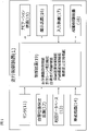
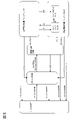
- FIG. 1 is a block diagram showing a configuration of a travel control device 1 for a vehicle (hereinafter, also referred to as “own vehicle”) according to the present embodiment.
- the travel control device 1 is also an embodiment for implementing the travel control method for a vehicle according to the present invention.
- the travel control device 1 includes a sensor 11, a vehicle position detection device 12, a map database 13, an in-vehicle device 14, a navigation device 15, a presentation device 16, an input device 17, a drive control device 18, and control.
- the device 19 is provided. These devices are connected by, for example, a CAN (Controller Area Network) or other in-vehicle LAN, and can transmit and receive information to and from each other.
- CAN Controller Area Network
- the sensor 11 detects the running state of the own vehicle.
- the sensor 11 includes a front camera that captures the front of the own vehicle, a rear camera that captures the rear of the own vehicle, and a side camera that captures the left and right sides of the own vehicle.
- the sensor 11 includes a front radar that detects an obstacle in front of the own vehicle, a rear radar that detects an obstacle behind the own vehicle, and a side radar that detects obstacles existing on the left and right sides of the own vehicle. Including radar such as.
- the sensor 11 includes a vehicle speed sensor that detects the vehicle speed of the own vehicle, a touch sensor (capacitance sensor) that detects the holding of the handle by the driver, a driver monitor that images the driver, and the like.
- the sensor 11 one of the plurality of sensors described above may be used, or two or more types of sensors may be used in combination.
- the detection result of the sensor 11 is acquired by the control device 19 at predetermined time intervals.
- the own vehicle position detection device 12 includes a GPS unit, a gyro sensor, a vehicle speed sensor, and the like.
- the own vehicle position detection device 12 detects radio waves transmitted from a plurality of satellite communications by the GPS unit, and periodically acquires the position information of the target vehicle (own vehicle). Further, the own vehicle position detection device 12 detects the current position of the target vehicle based on the acquired position information of the target vehicle, the angle change information acquired from the gyro sensor, and the vehicle speed acquired from the vehicle speed sensor.
- the position information of the target vehicle detected by the own vehicle position detection device 12 is acquired by the control device 19 at predetermined time intervals.
- the map database 13 is a memory that stores three-dimensional high-precision map information including location information of various facilities and specific points and is accessible from the control device 19.
- the three-dimensional high-precision map information is three-dimensional map information based on the road shape detected when traveling on an actual road using a data acquisition vehicle.
- the 3D high-precision map information, along with the map information, is detailed and highly accurate, such as the curved road and the size of the curve (for example, curvature or radius of curvature), the confluence of roads, branch points, toll stations, and the positions where the number of lanes is reduced.
- the position information of is the map information associated with the three-dimensional information.
- the in-vehicle device 14 is various devices mounted on the vehicle and operates by the operation of the driver. Such vehicle-mounted devices include steering wheels, accelerator pedals, brake pedals, turn signals, wipers, lights, horns, and other specific switches. When the in-vehicle device 14 is operated by the driver, the in-vehicle device 14 outputs the operation information to the control device 19.
- the navigation device 15 acquires the current position information of the own vehicle from the own vehicle position detection device 12, superimposes the position of the own vehicle on the map information for navigation, and displays it on a display or the like. Further, the navigation device 15 has a navigation function of setting a route to the destination and guiding the set route to the driver when the destination is set. With this navigation function, the navigation device 15 displays the route on the map of the display and informs the driver of the route by voice or the like.
- the presentation device 16 includes various displays such as a display included in the navigation device 15, a display incorporated in the rearview mirror, a display incorporated in the meter unit, and a head-up display projected on the windshield. Further, the presenting device 16 includes a device other than the display, such as a speaker of an audio device and a seat device in which a vibrating body is embedded. The presentation device 16 notifies the driver of various presentation information according to the control of the control device 19.
- the input device 17 is, for example, a device such as a button switch capable of inputting manually by a driver, a touch panel arranged on a display screen, or a microphone capable of inputting by voice of a driver.
- the driver can operate the input device 17 to input the setting information for the presentation information presented by the presentation device 16.
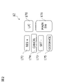
- FIG. 2 is a front view showing a part of the input device 17 of the present embodiment, and shows an example of a group of button switches arranged on the spokes of a handle or the like.
- the input device 17 is a button switch used when setting ON / OFF of the autonomous traveling control function (autonomous speed control function and autonomous steering control function) included in the control device 19.
- the input device 17 includes a main switch 171, a resume / accelerate switch 172, a set coast switch 173, a cancel switch 174, an inter-vehicle distance adjustment switch 175, and a lane change support switch 176.
- the main switch 171 is a switch that turns on / off the power of the system that realizes the autonomous speed control function and the autonomous steering control function of the control device 19.
- the resume / accelerate switch 172 stops the autonomous speed control function (OFF), then restarts the autonomous speed control function at the set speed before the OFF, increases the set speed, and controls after stopping following the preceding vehicle. It is a switch for restarting by the device 19.
- the set coast switch 173 is a switch that starts the autonomous speed control function at the traveling speed or lowers the set speed.
- the cancel switch 174 is a switch that turns off the autonomous speed control function.
- the inter-vehicle distance adjustment switch 175 is a switch for setting the inter-vehicle distance from the preceding vehicle, and is a switch for selecting one from a plurality of stages of settings such as short-distance, medium-distance, and long-distance.
- the lane change support switch 176 is a switch for instructing (accepting) the start of the lane change when the control device 19 confirms with the driver that the lane change has started. By operating the lane change support switch 176 for a longer time than a predetermined time after consenting to start the lane change, the approval of the lane change proposal by the control device 19 can be revoked.
- a direction indicator lever of a turn signal or a switch of another in-vehicle device 14 can be used as an input device 17.
- the control device 19 proposes whether or not to automatically change lanes
- the direction indicator lever is operated in the direction instead of the proposed lane change. Change lanes.
- the input device 17 outputs the input setting information to the control device 19.
- the drive control device 18 controls the running of the own vehicle. For example, when the own vehicle travels at a constant speed by the autonomous speed control function, the drive control device 18 accelerates and decelerates so that the own vehicle reaches the set speed, and maintains the traveling speed. Controls the operation of the drive mechanism and the braking operation. Further, the drive control device 18 similarly controls the operation of the drive mechanism and the brake even when the own vehicle follows the preceding vehicle by the autonomous speed control function.
- the drive control device 18 executes steering control of the own vehicle by controlling the operation of the steering actuator in addition to the operation control of the drive mechanism and the brake described above by the autonomous steering control function. For example, when the drive control device 18 executes lane keeping control by the autonomous steering control function, the drive control device 18 detects a lane marker in the own lane in which the own vehicle travels, and causes the own vehicle to travel in a predetermined position in the own lane. It controls the traveling position in the width direction of the own vehicle. Further, the drive control device 18 controls the traveling position in the width direction of the own vehicle so that the own vehicle changes lanes when the lane change support function is executed by the lane change support function described later.
- the drive control device 18 executes right / left turn support by the autonomous steering control function, the drive control device 18 performs traveling control for turning right or left at an intersection or the like.
- the drive control device 18 controls the traveling of the own vehicle according to the instruction of the control device 19 described later. Further, as a traveling control method by the drive control device 18, other known methods can also be used.
- the control device 19 includes a ROM (Read Only Memory) that stores a program for controlling the running of the own vehicle, a CPU (Central Processing Unit) that executes the program stored in the ROM, and an accessible storage device. It is equipped with a functioning RAM (RandomAccessMemory) and the like.
- RAM RandomAccessMemory
- MPU Micro Processing Unit
- DSP Digital Signal Processor
- ASIC Application Specific Integrated Circuit
- FPGA Field Programmable Gate Array
- the control device 19 has a traveling information acquisition function for acquiring information on the traveling state of the own vehicle by executing a program stored in the ROM by the CPU, a traveling scene determination function for determining the traveling scene of the own vehicle, and a self. It realizes an autonomous driving control function that autonomously controls the traveling speed and / or steering of the vehicle.
- the driving information acquisition function of the control device 19 is a function for the control device 19 to acquire driving information regarding the traveling state of the own vehicle.
- the control device 19 acquires image information outside the own vehicle captured by the front camera, the rear camera, and the side camera of the sensor 11 as driving information by the traveling information acquisition function. Further, the control device 19 acquires the detection results of the front radar, the rear radar, and the side radar as the travel information by the travel information acquisition function. Further, the control device 19 also acquires the vehicle speed information of the own vehicle detected by the vehicle speed sensor of the sensor 11 and the image information of the driver's face captured by the in-vehicle camera as the traveling information by the traveling information acquisition function.
- control device 19 acquires the current position information of the own vehicle from the own vehicle position detection device 12 as the running information by the traveling information acquisition function. Further, the control device 19 acquires the set destination and the route to the destination from the navigation device 15 as travel information by the travel information acquisition function. Further, the control device 19 uses a travel information acquisition function to provide travel information such as a curved road and the size of the curve (for example, curvature or radius of curvature), a confluence point, a branch point, a toll booth, and a position where the number of lanes is reduced. Is obtained from the map database 13. In addition, the control device 19 acquires the operation information of the vehicle-mounted device 14 by the driver from the vehicle-mounted device 14 as driving information by the traveling information acquisition function.
- travel information acquisition function to provide travel information such as a curved road and the size of the curve (for example, curvature or radius of curvature), a confluence point, a branch point, a toll booth, and a position where the number of lanes is reduced.
- the driving scene determination function of the control device 19 is a function of determining the driving scene in which the own vehicle is traveling by referring to the table stored in the ROM of the control device 19.
- a driving scene suitable for changing lanes or overtaking and a determination condition thereof are stored for each driving scene.
- the control device 19 refers to the table stored in the ROM by the traveling scene determination function, and determines whether or not the traveling scene of the own vehicle is a traveling scene suitable for, for example, changing lanes or overtaking.
- the control device 19 is detected by the traveling scene determination function, for example, the detection result by the front camera and the front radar included in the sensor 11, the vehicle speed of the own vehicle detected by the vehicle speed sensor, and the own vehicle position detection device 12. It is determined whether or not the own vehicle satisfies the above conditions based on the position information of the vehicle and the like. When the above conditions are satisfied, the control device 19 determines that the own vehicle is a "catch-up scene with the preceding vehicle".
- the autonomous travel control function of the control device 19 is a function for the control device 19 to autonomously control the travel of the own vehicle without depending on the operation of the driver.
- the autonomous travel control function of the control device 19 includes an autonomous speed control function for autonomously controlling the travel speed of the own vehicle and an autonomous steering control function for autonomously controlling the steering of the own vehicle.
- an autonomous speed control function for autonomously controlling the travel speed of the own vehicle
- an autonomous steering control function for autonomously controlling the steering of the own vehicle.
- ⁇ Autonomous speed control function> When the autonomous speed control function detects the preceding vehicle, the vehicle speed set by the driver is set as the upper limit, and the vehicle-to-vehicle distance is controlled so as to maintain the inter-vehicle distance according to the vehicle speed while following the preceding vehicle. While controlling the running motion of the own vehicle, it is a function of controlling the running motion of the own vehicle so that the vehicle runs at a constant speed at a vehicle speed set by the driver when the preceding vehicle is not detected. The former is also called inter-vehicle distance control, and the latter is also called constant speed control.
- the autonomous speed control function detects the speed limit of the traveling road from the road sign by the sensor 11, or acquires the speed limit from the map information of the map database 13, and automatically sets the speed limit to the set vehicle speed. May include a function to do.
- the driver To activate the autonomous speed control function, the driver first operates the resume / accelerate switch 172 or the set coast switch 173 of the input device 17 shown in FIG. 2 to input a desired traveling speed. For example, if the own vehicle is traveling at 70 km / h and the set coast switch 173 is pressed, the current traveling speed is set as it is, but if the speed desired by the driver is 80 km / h, resume acceleration is achieved.
- the switch 172 may be pressed multiple times to increase the set speed. On the contrary, assuming that the speed desired by the driver is 60 km / h, the set coast switch 173 may be pressed a plurality of times to reduce the set speed.
- inter-vehicle distance desired by the driver may be selected by operating the inter-vehicle distance adjustment switch 175 of the input device 17 shown in FIG. 2, for example, from a plurality of stages of settings such as short distance, medium distance, and long distance.
- the constant speed control is executed when it is detected by the front radar of the sensor 11 or the like that there is no preceding vehicle in front of the own lane.
- the control device 19 controls the operation of the drive mechanism such as the engine and the brake by the drive control device 18 while feeding back the vehicle speed data by the vehicle speed sensor so as to maintain the set running speed.
- Inter-vehicle distance control is executed when it is detected by the front radar of the sensor 11 or the like that a preceding vehicle exists in front of the own lane.
- the control device 19 feeds back the inter-vehicle distance data detected by the forward radar so as to maintain the set inter-vehicle distance with the set traveling speed as the upper limit, and the drive control device 18 causes the engine and the engine and the control device 19 to maintain the set inter-vehicle distance. Controls the operation of drive mechanisms such as brakes. If the preceding vehicle stops while traveling under the inter-vehicle distance control, the own vehicle also stops following the preceding vehicle.
- the own vehicle also starts and starts following running again by inter-vehicle distance control. If the own vehicle is stopped for more than 30 seconds, it will not start automatically even if the preceding vehicle starts, and if the preceding vehicle starts, press the resume / accelerate switch 172 or depress the accelerator pedal. , The follow-up running by the inter-vehicle distance control is started again.
- the autonomous steering control function is a function for the control device 19 to execute steering control of the own vehicle by controlling the operation of the steering actuator when a predetermined condition is satisfied during the execution of the above-mentioned autonomous speed control function.
- This autonomous steering control function includes, for example, a lane keeping function, a lane change support function, and the like.
- the lane keeping function is a function for assisting the driver in steering operation by controlling the steering actuator by the control device 19 so as to travel near the center of the lane, for example.
- the lane keeping function is also called a lane width direction maintenance function.
- FIG. 3 is a plan view showing a traveling scene in which a vehicle traveling in the own lane on the upper side of the drawing changes lanes to an adjacent lane on the lower side of the drawing on a road traveling from left to right in the drawing.
- the control device 19 turns on the turn signal when the driver operates the direction indicator lever, and when the preset lane change start condition is satisfied, the control device 19 changes the lane by the lane change support function.
- the lane change operation (hereinafter referred to as "LCP”), which is a series of processes of the above, is started.
- the control device 19 determines whether or not the lane change start condition is satisfied based on various driving information acquired by the driving information acquisition function by the lane change support function.
- the conditions for starting the lane change are not particularly limited, but the lane keep mode is in the hands-on mode, the hands-on judgment is in progress, the vehicle is traveling at a speed of 60 km / h or more, the lane is in the lane change direction, and the lane is changed. There is a space where you can change lanes in the destination lane, the type of lane marker can be changed, and the radius of curvature of the road is 250 m or more. Within 1 second after the driver operates the turn signal lever. It can be exemplified that all the conditions such as being satisfied are satisfied.
- the control device 19 determines that the lane change start condition is satisfied by the lane change support function even without the driver's instruction, the control device 19 notifies the driver by the presentation device 16 to propose the lane change to the driver. May be good.
- the lane keep mode of the hands-on mode will be described in detail later, but the autonomous speed control function and the lane keep function of the autonomous steering control function are being executed, and the driver's holding of the steering wheel is detected.
- “hands-on determination in progress” means a state in which the driver continues to hold the steering wheel.
- the control device 19 starts LCP by the lane change support function.
- the LCP includes lateral movement of the own vehicle to the adjacent lane and lane change maneuvering (hereinafter referred to as “LCM”) that actually moves to the adjacent lane.
- the control device 19 presents information indicating that the lane is automatically changed to the driver by the presenting device 16 while the LCP is being executed by the lane change support function, and calls attention to the surroundings.
- the control device 19 turns off the turn signal and starts executing the lane keeping function in the adjacent lane.
- a plurality of support levels are set in the driving support mode indicating the support mode in the driving operation support.
- the level of support is referred to as "support level”.
- the traveling operation of the present embodiment is various traveling operations including a lane change, for example, acceleration, deceleration, and steering to the right or left.
- the control device 19 autonomously controls the traveling of the own vehicle by combining the autonomous control of the traveling speed using the autonomous speed control function and the autonomous control of the steering operation using the autonomous steering control function by the lane change support function. , Achieve support for driving operations specified at each support level. That is, the control device 19 intervenes in the traveling motion of the vehicle within the range defined by each support level, and autonomously controls the traveling motion. For the traveling operation in which the control device 19 does not intervene, a manual operation by the driver is performed.
- the level of support is defined in, for example, SAE J3016: SEP2016, Taxonomy and Definitions for Terms Related to Driving Automation Systems for On-Road Motor Vehicles published by the American Society of Automotive Engineers (SAE). It can be set based on the level.
- support level 0 is a level at which the driver performs all the driving tasks necessary for the driving operation.
- the control device 19 continuously executes either autonomous speed control or autonomous steering control (not both at the same time) in a specific limited area, and the driver continuously executes either the autonomous speed control or the autonomous steering control of the own vehicle by the running speed of the own vehicle or steering.
- the level at which either steering (not both at the same time) is performed.
- control device 19 continuously executes autonomous speed control and autonomous steering control in a specific limited area, and the driver either runs the vehicle or steers the vehicle by steering (not both at the same time). ) Is the level to be executed.
- the support level 3 is a level at which the control device 19 continuously executes all driving tasks in a limited area.
- the support level 4 is a level at which the control device 19 executes all the operation tasks, and the response to the case where the control continuation is difficult is continuously executed in the limited area.
- Assistance level 5 is a level at which the control device 19 continuously and unlimitedly performs all driving tasks and responses to cases where continuation of control is difficult.
- Support level 1 corresponds to, for example, the control device 19 controlling the traveling speed of the own vehicle by autonomous speed control.
- the support level 2 corresponds to, for example, the control device 19 executing the lane keep mode of the hands-off mode by autonomous steering control. Therefore, the situation where the support level of the driving support mode is lowered is that, for example, when the own vehicle changes lanes from the own lane to the adjacent lane, the driving environment of the own vehicle changes and the control of the hands-off mode is continued. The condition is not satisfied, the lane keep mode of the hands-off mode cannot be maintained, and the vehicle shifts to the traveling speed control by the autonomous speed control.
- the support level of the driving support mode does not decrease while the own vehicle is autonomously following the preceding vehicle, and is maintained at least while the own vehicle is following at a traveling speed equal to or lower than the first traveling speed. It shall be done.
- the first traveling speed is such that the driver is required to monitor the autonomous traveling operation when the own vehicle autonomously follows the preceding vehicle by, for example, autonomous control of the traveling speed and the steering operation. It is a running speed that becomes.
- the first traveling speed can be set to a value within an appropriate range according to the traveling environment of the own vehicle such as the shape of the road and surrounding obstacles.
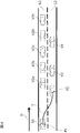
- FIG. 4 is a plan view showing a situation in which the own vehicle V1 travels on the road shown in FIG. 4, and the traveling direction of the road is the direction indicated by the arrow D in FIG.
- On the road there is a own lane L1 in which the own vehicle V1 travels and an adjacent lane L2 which is a lane adjacent to the own lane L1, and the preceding vehicles V2a to V2e travel in the own lane L1 and the preceding vehicles V3 and V4. Is traveling in the adjacent lane L2.
- FIG. 4 is a plan view showing a situation in which the own vehicle V1 travels on the road shown in FIG. 4, and the traveling direction of the road is the direction indicated by the arrow D in FIG.
- On the road there is a own lane L1 in which the own vehicle V1 travels and an adjacent lane L2 which is a lane adjacent to the own lane L1, and the preceding vehicles V2a to V2e travel in the own lane L1 and the preceding vehicles V3 and
- the adjacent lane L2 is a lane in which only a specific vehicle such as a carpool lane or a taxi lane can travel, and the own lane L1 is congested while the adjacent lane L2 is vacant. Further, it is assumed that the own vehicle V1 is executing the lane keep mode of the autonomous steering control / hands-off mode by following the preceding vehicle V2a.
- the control device 19 supports lane change in order to avoid congestion in the own lane L1 and maintain the set traveling speed.
- LCP from the own lane L1 to the adjacent lane L2 is started.
- the own vehicle V1 travels along the locus T from the traveling positions P1 to P2 by autonomous control by the control device 19.
- the own vehicle V1 cannot follow the preceding vehicle by changing lanes to the adjacent lane L2, and the support level of the driving support mode cannot be maintained. It will decrease.
- the driver's manual operation increases due to the autonomous lane change, which gives the driver a sense of discomfort.
- the driving information acquisition function uses a sensor 11 such as a front camera and a front radar.
- the preceding vehicle V3 traveling in the adjacent lane L2 is detected.
- the preceding vehicle V3 traveling in the adjacent lane L2 is not detected, in principle, the autonomous control of changing lanes of the own vehicle V1 is prohibited.
- the own vehicle is based on the traveling speed of the preceding vehicle V3 detected by the forward radar and the traveling speed of the own vehicle V1 detected by the vehicle speed sensor. It is determined whether or not V1 can follow the preceding vehicle V3.
- the own vehicle V1 it is determined whether or not the own vehicle V1 can follow the preceding vehicle V3 at a traveling speed equal to or lower than the first traveling speed. Then, when it is determined that the own vehicle V1 cannot follow the preceding vehicle V3, the autonomous control of changing the lane of the own vehicle V1 is prohibited.
- the control device 19 determines, for example, the traveling speed of the own vehicle V1 detected by the vehicle speed sensor and the traveling speed of the own vehicle V1 detected by the front radar. The difference from the traveling speed is calculated, and when the difference is equal to or less than a predetermined value, it is determined that the own vehicle V1 can follow the preceding vehicle V3.
- a predetermined value an appropriate value (for example, 0 to 10 km / h) can be set so that the own vehicle V1 can avoid a collision with the preceding vehicle V3.
- the predetermined time can be set to an appropriate time (for example, 5 to 10 seconds) at which the traveling state of the preceding vehicle V3 can be confirmed.
- the traveling speeds of the preceding vehicles V3 and V4 are detected, and the traveling speeds of the preceding vehicles V3 and V4 are used to detect a plurality of preceding vehicles V3 and V4.
- the average traveling speed of the vehicles V3 and V4 may be calculated and the average traveling speed may be set as the traveling speed of the preceding vehicle. Thereby, even when a plurality of preceding vehicles V3 and V4 are traveling in the adjacent lane L2, it is possible to appropriately determine whether or not the own vehicle V1 can follow the preceding vehicles V3 and V4.
- the number of preceding vehicles is not limited to two, and may be three or more.
- the own vehicle V1 follows the preceding vehicle V3 because the preceding vehicle traveling in the adjacent lane L2 is not detected or the traveling speed exceeds the first traveling speed. If it is determined that the vehicle cannot be changed, the autonomous control of changing the lane of the own vehicle V1 is prohibited. However, when the preceding vehicle traveling in the adjacent lane L2 is not detected, or when it is determined that the own vehicle V1 cannot follow the preceding vehicle V3, the own vehicle V1 before and after the lane change even if it does not follow the preceding vehicle.
- the second traveling speed which is the traveling speed at which the support level does not decrease
- the own vehicle V1 detects an obstacle in front by a sensor 11 such as a front camera and a front radar, and then can avoid the detected obstacle (for example, 60 km). / H) can be set. As a result, it is possible to avoid a situation in which the driver feels uncomfortable by continuing to drive in a congested lane.
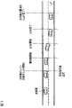
- FIG. 5 is a block diagram showing a state transition of each function established in the control device 19.
- the system shown in the figure means an autonomous traveling control system realized by the control device 19.
- the main switch 171 of FIG. 2 is turned on from the system OFF state shown in the figure, the system is put into the standby state. From this standby state, by turning on the set coast switch 173 or the resume acceleration switch 172 of FIG. 2, the autonomous speed control is activated.
- the above-mentioned constant speed control or inter-vehicle distance control is started, and the driver can drive his / her own vehicle simply by operating the steering wheel without stepping on the accelerator or the brake.
- the mode transitions to the lane keep mode of the autonomous steering control / hands-on mode.
- the condition (1) is not particularly limited, but the lane markers on both sides of the own vehicle are detected, the driver has a handle, the vehicle is traveling near the center of the lane, and the winker is activated. All conditions such as not having the wiper not operating at high speed (HI), and if there is a high-precision map, there are no tollhouses, exits, confluences, intersections, or lane reduction points within about 200 m ahead. Can be exemplified as the fact that is satisfied.
- the hands-on mode refers to a mode in which the autonomous steering control does not operate unless the driver holds the steering wheel
- the hands-off mode refers to a mode in which the autonomous steering control operates even if the driver releases his / her hand from the steering wheel.
- condition (2) in FIG. 5 If the condition (2) in FIG. 5 is satisfied while the lane keep mode of the autonomous steering control / hands-on mode is being executed, the mode transitions to the lane keep mode of the autonomous steering control / hands-off mode.
- the condition (2) is not particularly limited, but the vehicle is traveling on a motorway, is traveling on a road structurally separated from the oncoming lane, and is traveling on a road having a high-precision map. You are driving, you are driving at a vehicle speed below the speed limit, the GPS signal is valid, the driver has a handle, the driver is facing forward, and the toll booth is within about 800 m ahead.
- condition (3) in FIG. 5 is satisfied while the lane keep mode of the autonomous steering control / hands-off mode is being executed, the mode transitions to the lane keep mode of the autonomous steering control / hands-on mode.
- the condition (3) is not particularly limited, but the vehicle is traveling on a road other than a motorway, is traveling on a two-way traffic section, and is traveling on a road without a high-precision map.
- condition (4) in FIG. 5 is satisfied while the lane keep mode of the autonomous steering control / hands-off mode is being executed, the autonomous steering control is stopped and the process shifts to the autonomous speed control.
- the condition (4) is not particularly limited, but one of the following is that the lane markers on both sides of the own vehicle are not detected for a certain period of time, the driver operates the steering wheel, and the wiper operates at high speed (HI). It can be exemplified that the condition is satisfied. Further, if the condition (5) of FIG. 5 is satisfied while the lane keep mode of the autonomous steering control / hands-off mode is being executed, the autonomous steering control and the autonomous speed control are stopped and the state shifts to the standby state.
- the condition (5) is not particularly limited, but the driver operates the brake, the driver operates the cancel switch 174 in FIG. 2, the door of the own vehicle is opened, and the seat belt of the driver's seat is released. That, the seat sensor detected that the driver was no longer in the driver's seat, the select lever was other than "D” or "M”, the parking brake was activated, and the electronic stability control of the own vehicle It was turned off, the anti-skid device was activated, the snow mode was turned on, the emergency brake was activated, and after the vehicle stopped due to vehicle speed control, the stopped state continued for about 3 minutes.
- the front camera detected poor visibility such as dirt, backlight, rain / fog, etc., the front radar detected shielding, radio interference, the front radar detected axis misalignment, and the side. It can be exemplified that any of the conditions such as the radar detecting the shielding and the radio wave interference, and the side radar detecting the axis deviation are satisfied.
- condition (6) in FIG. 5 is satisfied while the autonomous steering control / hands-on mode is being executed, the autonomous steering control is stopped and the process shifts to the autonomous speed control.
- the condition (6) is not particularly limited, but the lane markers on both sides of the own vehicle are no longer detected, the driver operates the steering wheel, the driver operates the winker, and the wiper operates at high speed (HI). Either that, if there is a high-precision map, it became a tollhouse section, or that the front camera detected poor visibility that could not correctly recognize the object due to dirt, backlight, rain, fog, etc. You can exemplify what to do. Further, if the condition (7) of FIG.
- the condition (7) is not particularly limited, but the driver operates the brake, the driver operates the cancel switch 174 in FIG. 2, the door of the own vehicle is opened, and the seat belt of the driver's seat is released. That, the seating sensor detected that the driver was no longer in the driver's seat, the select lever was other than "D" or "M”, the parking brake was activated, and the electronic stability control of the own vehicle It was turned off, the anti-skid device was activated, the snow mode was turned on, the emergency brake was activated, and after the vehicle stopped due to vehicle speed control, the stopped state continued for about 3 minutes. It can be exemplified that any of the conditions such as the front radar detecting the shielding and the radio wave interference, and the front radar detecting the axis deviation are satisfied.
- the condition (8) in FIG. 5 is satisfied while the autonomous speed control is being executed, the state transitions to the standby state.
- the condition (8) is not particularly limited, but the driver operates the brake, the driver operates the cancel switch 174 in FIG. 2, the door of the own vehicle is opened, and the seat belt of the driver's seat is released. That, the seating sensor detected that the driver was no longer in the driver's seat, the select lever was other than "D” or "M”, the parking brake was activated, and the electronic stability control of the own vehicle It was turned off, the anti-skid device was activated, the snow mode was turned on, the emergency brake was activated, and after the vehicle stopped due to vehicle speed control, the stopped state continued for about 3 minutes. It can be exemplified that any of the conditions such as the front radar detecting the shielding and the radio wave interference, and the front radar detecting the axis deviation are satisfied.
- This condition (8) is not particularly limited, but is one of the conditions that the driver presses the lane change support switch 176 in FIG. 2 and the driver operates the turn signal when the system proposes a lane change. Can be exemplified as the fact that is satisfied.
- condition (10) in FIG. 5 is satisfied while the lane change mode of the autonomous steering control / hands-on mode is being executed, the mode transitions to the lane keep mode of the autonomous steering control / hands-on mode.
- This condition (10) is not particularly limited, but before the start of LCP, the speed limit was exceeded, before the start of LCP, the driver held the steering wheel and stepped on the accelerator pedal, and there was a slow car ahead. After pressing the lane change support switch 176 during the lane change proposal, the LCP could not be started within 10 seconds, and after pressing the lane change support switch 176 during the lane change proposal to drive according to the route.
- the LCP could not be started and the vehicle was too close to the branch, the actual LCM could not be started within 5 seconds after the LCP was activated, the LCP was started, and the vehicle speed was about 50 km / h before the LCM was started.
- the LCP was activated, there was no space in the adjacent lane required to change lanes before the LCM started, the driver canceled before the LCM started, and the lane marker was not before the LCM started. It was detected, it was determined that there was no adjacent lane L2 in the direction of changing lanes before the start of LCM, or there was no adjacent lane L2 within a certain distance ahead, and before the start of LCM, within a certain distance ahead.
- the driver did not have a handle within about 2 seconds after pressing the lane change support switch 176 while proposing a lane change when there was a slow car ahead without a handle, and the lane change to drive according to the route After pressing the lane change support switch 176 during the proposal, it was established under one of the conditions that the driver did not hold the handle within about 2 seconds), the driver turned off the winker, the LCP was completed, etc. It can be exemplified that any of the conditions is satisfied.
- the main switch 171 is turned off in any of the autonomous steering control / hands-off mode, autonomous steering control / hands-on mode, autonomous speed control, and standby state, the system is turned off.
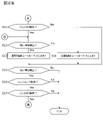
- 6A to 6B and FIG. 7 are flowcharts showing the traveling control process according to the present embodiment.
- 6A to 6B show basic travel control processing
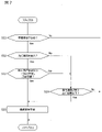
- FIG. 7 shows a subroutine in step S10 of FIG. 6A.
- the travel control process described below is executed by the control device 19 at predetermined time intervals. Further, in the following, autonomous speed control and autonomous steering control are executed by the autonomous driving control function of the control device 19, and the vehicle is driven in the lane at a speed set by the driver in the width direction of the vehicle. It is assumed that lane keep control for controlling the traveling position is performed.
- step S1 of FIG. 6A the control device 19 determines whether or not the main switch 171 is ON.
- step S1: No the control device 19 repeats step S1 until the main switch 171 is turned ON.
- step S1: Yes the process proceeds to step S2.
- step S2 the control device 19 determines whether or not the driver has set the traveling speed. If the traveling speed is not set (step S2: No), the process returns to step S1, and the control device 19 repeats steps S1 and S2 until the traveling speed is set. On the other hand, if the traveling speed is set (step S2: Yes), the process proceeds to step S3.
- the traveling speed is set by the driver by operating the resume accelerator switch 172 or the set coast switch 173 of the input device 17 shown in FIG. 2 to input a desired traveling speed.
- step S3 the control device 19 detects whether or not there is a preceding vehicle in front of the lane in which the own vehicle travels by using the forward radar (sensor 11) that detects an obstacle in front of the own vehicle. ..
- the process proceeds to step S4, and the control device 19 executes the inter-vehicle distance control.
- step S5 the control device 19 executes constant speed control.
- the driver can drive the vehicle at a desired speed simply by operating the steering wheel without stepping on the accelerator or the brake.
- step S6 the condition (1) that the control device 19 transitions to the lane keep mode of the above-mentioned autonomous steering control / hands-on mode is satisfied. Determine if it holds. If the condition (1) is not satisfied (step S6: No), the process returns to step S3, and inter-vehicle distance control or constant speed control is continued. On the other hand, if the condition (1) is satisfied (step S6: Yes), the process proceeds to step S7.
- step S7 the control device 19 detects whether or not there is a preceding vehicle in front of the lane in which the own vehicle travels by using the forward radar (sensor 11) that detects an obstacle in front of the own vehicle.
- step S7: Yes the control device 19 proceeds to step S8 to execute the inter-vehicle distance control / lane keep mode.
- step S9 the control device 19 proceeds to step S9 to execute the constant speed control / lane keep mode. In this state, the execution process of the lane change support function in step S10 is performed. The details of step S10 will be described later.
- step S11 of FIG. 6B the control device 19 has the above-mentioned automatic steering control / hands-off. It is determined whether or not the condition (2) for transitioning to the mode is satisfied. If the condition (2) is satisfied (step S11: Yes), the process proceeds to step S12. On the other hand, if the condition (2) is not satisfied (step S11: No), the process proceeds to step S15 described later.
- step S12 in which the condition (2) for transitioning to the automatic steering control / hands-off mode is satisfied, the control device 19 uses the front radar (sensor 11) to detect an obstacle in front of the own vehicle, and the own vehicle moves. Detects whether or not there is a preceding vehicle in front of the driving lane.
- step S12: Yes the control device 19 proceeds to step S13 to execute inter-vehicle distance control, lane keep mode, and hands-off.
- step S12: No the control device 19 proceeds to step S14 to execute constant speed control, lane keep mode, and hands-off.
- step S15 the control device 19 detects whether or not there is a preceding vehicle in front of the lane in which the own vehicle travels by using the forward radar (sensor 11) that detects an obstacle in front of the own vehicle. .. If the preceding vehicle is not detected (step S15: No), the process returns to step S1, and the control device 19 continues the subsequent processing. On the other hand, when detecting the preceding vehicle (step S15: Yes), the control device 19 proceeds to step S16.
- step S16 similarly to step S6, the control device 19 determines whether or not the condition (1) for transitioning to the lane keep mode of the autonomous steering control / hands-on mode is satisfied. If the condition (1) is not satisfied (step S16: No), the process returns to step S1, and the control device 19 continues the subsequent processing. On the other hand, if the condition (1) is satisfied (step S16: Yes), the process proceeds to step S17.
- step S17 the control device 19 determines whether or not the condition (2) for transitioning to the automatic steering control / hands-off mode is satisfied, as in step S11. If the condition (2) is satisfied (step S17: Yes), the process returns to step S12 and the subsequent processing is continued. On the other hand, if the condition (2) is not satisfied (step S17: No), the process returns to step S1 and the control device 19 continues the subsequent processing.
- step S10 of FIG. 6A the process shown in FIG. 7 is executed as the execution process of the lane change support function.
- the control device 19 determines whether or not the own vehicle V1 needs to change lanes. For the determination, the route to the destination set by the navigation device 15 is used. If it is determined that the lane change is not necessary (step S21: No), the process proceeds to step S11 without executing the lane change support, and the traveling control process is continued. On the other hand, if it is determined that the lane change is necessary (step S21: Yes), the process proceeds to step S22.
- step S22 the control device 19 uses the front radar and the front camera (sensor 11) to detect an obstacle in front of the own vehicle V1 and travels in front of the own vehicle V1 in the adjacent lane L2. Detects if is present.
- step S22: Yes the process proceeds to step S23.
- step S22: No the process proceeds to step S24.
- step S23 the control device 19 determines whether or not the own vehicle V1 can follow the preceding vehicle V3 detected in step S22 at a traveling speed equal to or lower than the first traveling speed. For the determination, for example, the traveling speed of the own vehicle V1 detected by the vehicle speed sensor and the traveling speed of the preceding vehicle detected by the front radar are used, and for example, the difference in the traveling speed between the own vehicle V1 and the preceding vehicle V3 is determined. It is determined whether or not it is equal to or less than the set predetermined value.
- step S23: Yes If it is determined that the own vehicle V1 can follow the preceding vehicle V3 at a running speed equal to or lower than the first running speed (step S23: Yes), the process proceeds to step S25, and the control device 19 uses the lane change support function to support the own vehicle. Autonomous control of V1 lane change. On the other hand, if it is determined that the own vehicle V1 cannot follow the preceding vehicle V3 at a traveling speed equal to or lower than the first traveling speed (step S23: No), the process proceeds to step S24.
- step S24 the control device 19 lowers the support level of the own vehicle V1 before and after the lane change from the own lane L2 to the adjacent lane L2 even if the traveling speed of the own vehicle V1 does not follow the preceding vehicle V3. It is determined whether or not the running speed is equal to or less than the second running speed.
- the traveling speed of the own vehicle V1 is detected by using the vehicle speed sensor (sensor 11). If it is determined that the traveling speed of the own vehicle V1 is equal to or less than the second traveling speed (step S24: Yes), the process proceeds to step S25, and the control device 19 autonomously controls the lane change of the own vehicle V1 by the lane change support function. do. On the other hand, if it is determined that the traveling speed of the own vehicle V1 exceeds the second traveling speed (step S24: No), the vehicle proceeds to step S11 without executing the lane change support, and the traveling control process is continued.
- the driving support mode for supporting the driving operation of the driver by using the autonomous driving control including the autonomous control of the traveling speed and the steering operation is set.
- a support level is set to indicate how much autonomous driving control intervenes in the driving motion of the vehicle, and the support level is at least the first support level and the intervention of autonomous driving control rather than the first support level.
- the second support level is set, and the support level is set when the own vehicle V1 does not decrease from the first support level to the second support level while following the preceding vehicle V3 by autonomous driving control.
- the own vehicle V1 changes lanes from the own lane L1 in which the own vehicle V1 travels to the adjacent lane L2 of the own lane V1
- the preceding vehicle V3 traveling in the adjacent lane L2 is detected and the own vehicle V1 travels in the adjacent lane L2.
- the autonomous control of changing the lane of the own vehicle V1 is prohibited.
- the own vehicle V1 cannot follow the preceding vehicle, and the support level of the driving support mode cannot be maintained, and it is possible to avoid a decrease.
- the preceding vehicle V3 traveling in the adjacent lane L2 is detected, and when the preceding vehicle V3 traveling in the adjacent lane L2 is detected, the preceding vehicle V3 is detected. It is determined whether or not the own vehicle V1 can autonomously follow the detected preceding vehicle V3, and when it is determined that the own vehicle V1 cannot autonomously follow the detected preceding vehicle V3, the lane change of the own vehicle V1 is performed. Prohibit autonomous control of. Thereby, it is possible to determine whether or not the autonomous control of changing the lane of the own vehicle V1 is prohibited according to the traveling state of the preceding vehicle V3.
- the own vehicle V1 when it is determined whether or not the own vehicle V1 can autonomously follow the detected preceding vehicle V3, the own vehicle V1 travels.
- the speed and the traveling speed of the preceding vehicle V3 are detected, the difference between the traveling speed of the own vehicle V1 and the traveling speed of the preceding vehicle V3 is calculated, and when the difference is equal to or less than a predetermined value, the own vehicle V1 It is determined that the vehicle can follow the preceding vehicle V3. As a result, the collision between the own vehicle V1 and the preceding vehicle V3 can be further avoided.
- the situation where the difference between the travel speed of the own vehicle V1 and the travel speed of the preceding vehicle V3 is not more than a predetermined value is more than a predetermined time.
- the collision between the own vehicle V1 and the preceding vehicle V3 can be further avoided.
- the traveling speeds of the preceding vehicles V3 and V4 are detected and the preceding vehicles V3 and V4 are detected.
- the average traveling speed of the plurality of preceding vehicles V3 and V4 is calculated from the traveling speeds of the vehicles V3 and V4, and the average traveling speed is set as the traveling speed of the preceding vehicle.
- the driver monitors the autonomous travel operation when the own vehicle V1 autonomously follows the preceding vehicle by the autonomous travel control.
- the preceding vehicle V3 traveling in the adjacent lane L2 is detected in the case where the first traveling speed is set, the preceding traveling speed detected at the traveling speed equal to or lower than the first traveling speed is detected.
- the own vehicle V1 can autonomously follow the vehicle V3
- the own vehicle V1 Prohibit autonomous control of lane changes. As a result, it is possible to avoid a situation in which the driver needs to monitor due to autonomous lane change. As a result, it is possible to avoid a situation in which the driver feels uncomfortable that monitoring is required due to lane change support.
- the support level of the own vehicle V1 changes from the first support level to the second support level before and after the lane change even if the vehicle does not follow the preceding vehicle.
- the second traveling speed which is the traveling speed that does not decrease to the above
- the preceding vehicle V3 traveling in the adjacent lane L2 is not detected, or when the preceding vehicle V3 traveling in the adjacent lane L2 is autonomous.
- the adjacent lane L2 is a lane in which only a specific vehicle can travel. This makes it possible to determine whether or not autonomous control of lane change is prohibited according to the driving environment of the road.
- Driving control device 11 Sensor 12 ... Own vehicle position detection device 13 ... Map database 14 ... In-vehicle device 15 ... Navigation device 16 ... Presentation device 17 ... Input device 171 ... Main switch 172 ... Resume / accelerate switch 173 ... Set Coast switch 174 ... Cancel switch 175 ... Inter-vehicle adjustment switch 176 ... Lane change support switch 18 ... Drive control device 19 ... Control device V1 ... Own vehicle V2, V2a, V2b, V2c, V2d, V2e ... Leading vehicle (own lane) V3, V4 ... Leading vehicle (adjacent lane) L1 ... own lane L2 ... adjacent lane D ... traveling direction P1, P2 ... traveling position T ... locus
Abstract
Provided is a travel control method in which: at least a first assistance level and a second assistance level lower in autonomous travel control intervention level than the first assistance level are set as assistance levels that indicate levels for determining to what extent autonomous travel control intervenes in the traveling operation of a vehicle; and when a host vehicle (V1) is autonomously following a preceding vehicle (V3) through autonomous travel control and the assistance level does not decrease from the first assistance level to the second assistance level, if the host vehicle (V1) is to change lanes from the current lane (L1) in which the host vehicle (V1) is traveling to an adjacent lane (L2) to the current lane (L1), an attempt is made to detect the preceding vehicle (V3) traveling in the adjacent lane (L2), and if no preceding vehicles traveling in the adjacent lane (L2) are detected, autonomous control of the lane change by the host vehicle (V1) is prohibited.
Description
本発明は、車両の走行制御方法及び走行制御装置に関するものである。
The present invention relates to a vehicle travel control method and a travel control device.
走行車線から隣接車線への車線変更を制御する場合に、地図情報及び地図情報における車両の位置から、車線変更可能区間の一つ手前の車線変更禁止区間を車両が走行中であると判定し、さらに、車両に接近又は近接する後続車が存在すると判定したときに、車線変更の開始位置に車両が到達する前に、隣接車線側の方向指示器をオンにする技術が知られている(特許文献1)。これにより、後続車の追い越しを止めることができ、後続車による車線変更制御の中止や遅延を抑制することができる。
When controlling a lane change from a driving lane to an adjacent lane, it is determined from the map information and the position of the vehicle in the map information that the vehicle is traveling in the lane change prohibited section immediately before the lane changeable section. Further, there is known a technique of turning on a turn signal on the adjacent lane side before the vehicle reaches the start position of the lane change when it is determined that there is a following vehicle approaching or close to the vehicle (patented patent). Document 1). As a result, it is possible to stop the overtaking of the following vehicle, and it is possible to suppress the cancellation or delay of the lane change control by the following vehicle.
車両の走行制御方法では、走行速度及び操舵操作の自律制御を含む自律走行制御を用いてドライバーの運転を支援する運転支援モードに、複数の支援レベルが設定されている場合がある。この場合に、上記従来技術のように、地図情報及び地図情報における車両の位置を用いて、車線変更が可能である場合に自律的に車線変更を実行すると、車線変更後に、車線変更前の支援レベルの条件を満たさなくなることがある。この結果、車線変更により支援レベルが低下することになる。
In the vehicle driving control method, a plurality of support levels may be set in the driving support mode that supports the driver's driving by using the autonomous driving control including the autonomous control of the traveling speed and the steering operation. In this case, if the lane change is autonomously executed when the lane change is possible by using the map information and the vehicle position in the map information as in the above-mentioned prior art, the support after the lane change and before the lane change is performed. May not meet the level requirements. As a result, the level of support will decrease due to lane changes.
本発明が解決しようとする課題は、自律的な車線変更による支援レベルの低下を回避することができる走行制御方法及び走行制御装置を提供することである。
An object to be solved by the present invention is to provide a travel control method and a travel control device capable of avoiding a decrease in the support level due to an autonomous lane change.
本発明は、自律走行制御を用いてドライバーの運転操作を支援する運転支援モードに、自車両の走行動作に対して自律走行制御が介入する程度の水準を示す支援レベルが設定され、自車両が自律走行制御により先行車両に自律的に追従している間は、当該支援レベルが低下しない場合において、自車両が、自車両が走行する自車線から、自車線の隣接車線に車線変更するときに、隣接車線を走行する先行車両を検出し、隣接車線を走行する先行車両を検出しないときは、自車両の車線変更の自律制御を禁止することで上記課題を解決する。
In the present invention, a support level indicating a level at which autonomous driving control intervenes in the driving motion of the own vehicle is set in a driving support mode that assists the driver's driving operation by using autonomous driving control, and the own vehicle is set. When the own vehicle changes lanes from the own lane in which the own vehicle is traveling to the adjacent lane of the own lane when the support level does not decrease while autonomously following the preceding vehicle by the autonomous driving control. When the preceding vehicle traveling in the adjacent lane is detected and the preceding vehicle traveling in the adjacent lane is not detected, the above problem is solved by prohibiting the autonomous control of changing the lane of the own vehicle.
本発明によれば、自律的な車線変更による支援レベルの低下を回避することができる。
According to the present invention, it is possible to avoid a decrease in the support level due to an autonomous lane change.
以下、本発明の実施形態を図面に基づいて説明する。
Hereinafter, embodiments of the present invention will be described with reference to the drawings.
[走行制御装置]
図1は、本実施形態に係る車両(以下、「自車両」ともいう。)の走行制御装置1の構成を示すブロック図である。走行制御装置1は、本発明に係る車両の走行制御方法を実施する一実施の形態でもある。図1に示すように、走行制御装置1は、センサ11、自車位置検出装置12、地図データベース13、車載機器14、ナビゲーション装置15、提示装置16、入力装置17、駆動制御装置18、及び制御装置19を備える。これらの装置は、たとえばCAN(Controller Area Network)その他の車載LANにより接続され、相互に情報の送受信を行うことができる。 [Driving control device]
FIG. 1 is a block diagram showing a configuration of a travel control device 1 for a vehicle (hereinafter, also referred to as “own vehicle”) according to the present embodiment. The travel control device 1 is also an embodiment for implementing the travel control method for a vehicle according to the present invention. As shown in FIG. 1, the travel control device 1 includes a sensor 11, a vehicle position detection device 12, a map database 13, an in-vehicle device 14, a navigation device 15, a presentation device 16, aninput device 17, a drive control device 18, and control. The device 19 is provided. These devices are connected by, for example, a CAN (Controller Area Network) or other in-vehicle LAN, and can transmit and receive information to and from each other.
図1は、本実施形態に係る車両(以下、「自車両」ともいう。)の走行制御装置1の構成を示すブロック図である。走行制御装置1は、本発明に係る車両の走行制御方法を実施する一実施の形態でもある。図1に示すように、走行制御装置1は、センサ11、自車位置検出装置12、地図データベース13、車載機器14、ナビゲーション装置15、提示装置16、入力装置17、駆動制御装置18、及び制御装置19を備える。これらの装置は、たとえばCAN(Controller Area Network)その他の車載LANにより接続され、相互に情報の送受信を行うことができる。 [Driving control device]
FIG. 1 is a block diagram showing a configuration of a travel control device 1 for a vehicle (hereinafter, also referred to as “own vehicle”) according to the present embodiment. The travel control device 1 is also an embodiment for implementing the travel control method for a vehicle according to the present invention. As shown in FIG. 1, the travel control device 1 includes a sensor 11, a vehicle position detection device 12, a map database 13, an in-vehicle device 14, a navigation device 15, a presentation device 16, an
センサ11は、自車両の走行状態を検出する。センサ11は、自車両の前方を撮像する前方カメラ、自車両の後方を撮像する後方カメラ、自車両の左右の側方を撮像する側方カメラ等のカメラを含む。また、センサ11は、自車両の前方の障害物を検出する前方レーダー、自車両の後方の障害物を検出する後方レーダー、自車両の左右の側方に存在する障害物を検出する側方レーダー等のレーダーを含む。さらに、センサ11は、自車両の車速を検出する車速センサ、ドライバーによるハンドルの保持を検出するタッチセンサ(静電容量センサ)およびドライバーを撮像するドライバーモニター等を含む。センサ11として、上述した複数のセンサのうち1つを用いてもよく、2種類以上のセンサを組み合わせて用いてもよい。センサ11の検出結果は、所定時間間隔で制御装置19により取得される。
The sensor 11 detects the running state of the own vehicle. The sensor 11 includes a front camera that captures the front of the own vehicle, a rear camera that captures the rear of the own vehicle, and a side camera that captures the left and right sides of the own vehicle. Further, the sensor 11 includes a front radar that detects an obstacle in front of the own vehicle, a rear radar that detects an obstacle behind the own vehicle, and a side radar that detects obstacles existing on the left and right sides of the own vehicle. Including radar such as. Further, the sensor 11 includes a vehicle speed sensor that detects the vehicle speed of the own vehicle, a touch sensor (capacitance sensor) that detects the holding of the handle by the driver, a driver monitor that images the driver, and the like. As the sensor 11, one of the plurality of sensors described above may be used, or two or more types of sensors may be used in combination. The detection result of the sensor 11 is acquired by the control device 19 at predetermined time intervals.
自車位置検出装置12は、GPSユニット、ジャイロセンサ、および車速センサ等を備える。自車位置検出装置12は、GPSユニットにより複数の衛星通信から送信される電波を検出し、対象車両(自車両)の位置情報を周期的に取得する。また、自車位置検出装置12は、取得した対象車両の位置情報と、ジャイロセンサから取得した角度変化情報と、車速センサから取得した車速とに基づいて、対象車両の現在位置を検出する。自車位置検出装置12が検出した対象車両の位置情報は、所定時間間隔で制御装置19により取得される。
The own vehicle position detection device 12 includes a GPS unit, a gyro sensor, a vehicle speed sensor, and the like. The own vehicle position detection device 12 detects radio waves transmitted from a plurality of satellite communications by the GPS unit, and periodically acquires the position information of the target vehicle (own vehicle). Further, the own vehicle position detection device 12 detects the current position of the target vehicle based on the acquired position information of the target vehicle, the angle change information acquired from the gyro sensor, and the vehicle speed acquired from the vehicle speed sensor. The position information of the target vehicle detected by the own vehicle position detection device 12 is acquired by the control device 19 at predetermined time intervals.
地図データベース13は、各種施設や特定の地点の位置情報を含む三次元高精度地図情報を格納し、制御装置19からアクセス可能とされたメモリである。三次元高精度地図情報は、データ取得用車両を用いて実際の道路を走行した際に検出された道路形状に基づく三次元地図情報である。三次元高精度地図情報は、地図情報とともに、カーブ路及びそのカーブの大きさ(たとえば曲率又は曲率半径)、道路の合流地点、分岐地点、料金所、車線数の減少位置などの詳細かつ高精度の位置情報が、三次元情報として関連付けられた地図情報である。
The map database 13 is a memory that stores three-dimensional high-precision map information including location information of various facilities and specific points and is accessible from the control device 19. The three-dimensional high-precision map information is three-dimensional map information based on the road shape detected when traveling on an actual road using a data acquisition vehicle. The 3D high-precision map information, along with the map information, is detailed and highly accurate, such as the curved road and the size of the curve (for example, curvature or radius of curvature), the confluence of roads, branch points, toll stations, and the positions where the number of lanes is reduced. The position information of is the map information associated with the three-dimensional information.
車載機器14は、車両に搭載された各種機器であり、ドライバーの操作により動作する。このような車載機器としては、ハンドル、アクセルペダル、ブレーキペダル、方向指示器、ワイパー、ライト、クラクション、その他の特定のスイッチなどが挙げられる。車載機器14は、ドライバーにより操作された場合に、その操作情報を制御装置19に出力する。
The in-vehicle device 14 is various devices mounted on the vehicle and operates by the operation of the driver. Such vehicle-mounted devices include steering wheels, accelerator pedals, brake pedals, turn signals, wipers, lights, horns, and other specific switches. When the in-vehicle device 14 is operated by the driver, the in-vehicle device 14 outputs the operation information to the control device 19.
ナビゲーション装置15は、自車位置検出装置12から自車両の現在の位置情報を取得し、ナビゲーション用の地図情報に自車両の位置を重ね合わせてディスプレイなどに表示する。また、ナビゲーション装置15は、目的地が設定された場合に、その目的地までのルートを設定し、設定したルートをドライバーに案内するナビゲーション機能を備える。このナビゲーション機能により、ナビゲーション装置15は、ディスプレイの地図上にルートを表示し、音声等によってルートをドライバーに知らせる。
The navigation device 15 acquires the current position information of the own vehicle from the own vehicle position detection device 12, superimposes the position of the own vehicle on the map information for navigation, and displays it on a display or the like. Further, the navigation device 15 has a navigation function of setting a route to the destination and guiding the set route to the driver when the destination is set. With this navigation function, the navigation device 15 displays the route on the map of the display and informs the driver of the route by voice or the like.
提示装置16は、ナビゲーション装置15が備えるディスプレイ、ルームミラーに組み込まれたディスプレイ、メーター部に組み込まれたディスプレイ、フロントガラスに映し出されるヘッドアップディスプレイ等の各種ディスプレイを含む。また、提示装置16は、オーディオ装置のスピーカー、振動体が埋設された座席シート装置など、ディスプレイ以外の装置を含む。提示装置16は、制御装置19の制御に従って、各種の提示情報をドライバーに報知する。
The presentation device 16 includes various displays such as a display included in the navigation device 15, a display incorporated in the rearview mirror, a display incorporated in the meter unit, and a head-up display projected on the windshield. Further, the presenting device 16 includes a device other than the display, such as a speaker of an audio device and a seat device in which a vibrating body is embedded. The presentation device 16 notifies the driver of various presentation information according to the control of the control device 19.
入力装置17は、たとえば、ドライバーの手動操作による入力が可能なボタンスイッチ、ディスプレイ画面上に配置されたタッチパネル、又はドライバーの音声による入力が可能なマイクなどの装置である。本実施形態では、ドライバーが入力装置17を操作することで、提示装置16により提示された提示情報に対する設定情報を入力することができる。図2は、本実施形態の入力装置17の一部を示す正面図であり、ハンドルのスポーク部などに配置されたボタンスイッチ群からなる一例を示す。入力装置17は、制御装置19が備える自律走行制御機能(自律速度制御機能及び自律操舵制御機能)のON/OFF等を設定する際に使用するボタンスイッチである。入力装置17は、メインスイッチ171、リジューム・アクセラレートスイッチ172、セット・コーストスイッチ173、キャンセルスイッチ174、車間調整スイッチ175、及び車線変更支援スイッチ176を備える。
The input device 17 is, for example, a device such as a button switch capable of inputting manually by a driver, a touch panel arranged on a display screen, or a microphone capable of inputting by voice of a driver. In the present embodiment, the driver can operate the input device 17 to input the setting information for the presentation information presented by the presentation device 16. FIG. 2 is a front view showing a part of the input device 17 of the present embodiment, and shows an example of a group of button switches arranged on the spokes of a handle or the like. The input device 17 is a button switch used when setting ON / OFF of the autonomous traveling control function (autonomous speed control function and autonomous steering control function) included in the control device 19. The input device 17 includes a main switch 171, a resume / accelerate switch 172, a set coast switch 173, a cancel switch 174, an inter-vehicle distance adjustment switch 175, and a lane change support switch 176.
メインスイッチ171は、制御装置19の自律速度制御機能及び自律操舵制御機能を実現するシステムの電源をON/OFFするスイッチである。リジューム・アクセラレートスイッチ172は、自律速度制御機能を停止(OFF)したのちOFF前の設定速度で自律速度制御機能を再開したり、設定速度を上げたり、先行車両に追従して停車したのち制御装置19によって再発進させたりするためのスイッチである。セット・コーストスイッチ173は、走行時の速度で自律速度制御機能を開始したり、設定速度を下げたりするスイッチである。キャンセルスイッチ174は、自律速度制御機能をOFFするスイッチである。車間調整スイッチ175は、先行車両との車間距離を設定するためのスイッチであり、たとえば短距離・中距離・長距離といった複数段の設定から1つを選択するスイッチである。車線変更支援スイッチ176は、制御装置19が車線変更の開始をドライバーに確認した場合に車線変更の開始を指示する(承諾する)ためのスイッチである。なお、車線変更の開始を承諾した後に、車線変更支援スイッチ176を所定時間よりも長く操作することで、制御装置19による車線変更の提案の承諾を取り消すことができる。
The main switch 171 is a switch that turns on / off the power of the system that realizes the autonomous speed control function and the autonomous steering control function of the control device 19. The resume / accelerate switch 172 stops the autonomous speed control function (OFF), then restarts the autonomous speed control function at the set speed before the OFF, increases the set speed, and controls after stopping following the preceding vehicle. It is a switch for restarting by the device 19. The set coast switch 173 is a switch that starts the autonomous speed control function at the traveling speed or lowers the set speed. The cancel switch 174 is a switch that turns off the autonomous speed control function. The inter-vehicle distance adjustment switch 175 is a switch for setting the inter-vehicle distance from the preceding vehicle, and is a switch for selecting one from a plurality of stages of settings such as short-distance, medium-distance, and long-distance. The lane change support switch 176 is a switch for instructing (accepting) the start of the lane change when the control device 19 confirms with the driver that the lane change has started. By operating the lane change support switch 176 for a longer time than a predetermined time after consenting to start the lane change, the approval of the lane change proposal by the control device 19 can be revoked.
図2に示すボタンスイッチ群以外にも、方向指示器の方向指示レバーやその他の車載機器14のスイッチを入力装置17として用いることができる。たとえば、制御装置19から自動で車線変更を行うか否かを提案された場合に、ドライバーが方向指示レバーを操作すると、提案された車線変更ではなく、方向指示レバーが操作された方向に向かって車線変更を行う。入力装置17は、入力された設定情報を制御装置19に出力する。
In addition to the button switch group shown in FIG. 2, a direction indicator lever of a turn signal or a switch of another in-vehicle device 14 can be used as an input device 17. For example, when the control device 19 proposes whether or not to automatically change lanes, when the driver operates the direction indicator lever, the direction indicator lever is operated in the direction instead of the proposed lane change. Change lanes. The input device 17 outputs the input setting information to the control device 19.
駆動制御装置18は、自車両の走行を制御する。たとえば、駆動制御装置18は、自律速度制御機能により自車両が設定速度で定速走行する場合には、自車両が設定速度となるように、加速および減速、並びに走行速度を維持するために、駆動機構の動作およびブレーキ動作を制御する。また、駆動制御装置18は、自律速度制御機能により自車両が先行車両に追従走行する場合にも、同様に駆動機構及びブレーキの動作を制御する。
The drive control device 18 controls the running of the own vehicle. For example, when the own vehicle travels at a constant speed by the autonomous speed control function, the drive control device 18 accelerates and decelerates so that the own vehicle reaches the set speed, and maintains the traveling speed. Controls the operation of the drive mechanism and the braking operation. Further, the drive control device 18 similarly controls the operation of the drive mechanism and the brake even when the own vehicle follows the preceding vehicle by the autonomous speed control function.
また、駆動制御装置18は、自律操舵制御機能により、上述した駆動機構とブレーキの動作制御に加えて、ステアリングアクチュエータの動作を制御することで、自車両の操舵制御を実行する。たとえば、駆動制御装置18は、自律操舵制御機能によりレーンキープ制御を実行する場合に、自車両が走行する自車線のレーンマーカを検出し、自車両が自車線内の所定位置を走行するように、自車両の幅員方向における走行位置を制御する。また、駆動制御装置18は、後述する車線変更支援機能により車線変更支援を実行する場合に、自車両が車線変更を行うように、自車両の幅員方向における走行位置を制御する。さらに、駆動制御装置18は、自律操舵制御機能により右左折支援を実行する場合には、交差点などにおいて右折又は左折する走行制御を行う。なお、駆動制御装置18は、後述する制御装置19の指示により自車両の走行を制御する。また、駆動制御装置18による走行制御方法として、その他の公知の方法を用いることもできる。
Further, the drive control device 18 executes steering control of the own vehicle by controlling the operation of the steering actuator in addition to the operation control of the drive mechanism and the brake described above by the autonomous steering control function. For example, when the drive control device 18 executes lane keeping control by the autonomous steering control function, the drive control device 18 detects a lane marker in the own lane in which the own vehicle travels, and causes the own vehicle to travel in a predetermined position in the own lane. It controls the traveling position in the width direction of the own vehicle. Further, the drive control device 18 controls the traveling position in the width direction of the own vehicle so that the own vehicle changes lanes when the lane change support function is executed by the lane change support function described later. Further, when the drive control device 18 executes right / left turn support by the autonomous steering control function, the drive control device 18 performs traveling control for turning right or left at an intersection or the like. The drive control device 18 controls the traveling of the own vehicle according to the instruction of the control device 19 described later. Further, as a traveling control method by the drive control device 18, other known methods can also be used.
制御装置19は、自車両の走行を制御するためのプログラムを格納したROM(Read Only Memory)と、このROMに格納されたプログラムを実行するCPU(Central Processing Unit)と、アクセス可能な記憶装置として機能するRAM(Random Access Memory)等を備える。なお、動作回路としては、CPU(Central Processing Unit)に代えて又はこれとともに、MPU(Micro Processing Unit)、DSP(Digital Signal Processor)、ASIC(Application Specific Integrated Circuit)、FPGA(Field Programmable Gate Array)などを用いることができる。
The control device 19 includes a ROM (Read Only Memory) that stores a program for controlling the running of the own vehicle, a CPU (Central Processing Unit) that executes the program stored in the ROM, and an accessible storage device. It is equipped with a functioning RAM (RandomAccessMemory) and the like. As the operating circuit, instead of the CPU (Central Processing Unit) or together with it, MPU (Micro Processing Unit), DSP (Digital Signal Processor), ASIC (Application Specific Integrated Circuit), FPGA (Field Programmable Gate Array), etc. Can be used.
[制御装置の機能]
制御装置19は、ROMに格納されたプログラムをCPUにより実行することにより、自車両の走行状態に関する情報を取得する走行情報取得機能と、自車両の走行シーンを判定する走行シーン判定機能と、自車両の走行速度及び/又は操舵を自律制御する自律走行制御機能とを実現する。 [Control device functions]
The control device 19 has a traveling information acquisition function for acquiring information on the traveling state of the own vehicle by executing a program stored in the ROM by the CPU, a traveling scene determination function for determining the traveling scene of the own vehicle, and a self. It realizes an autonomous driving control function that autonomously controls the traveling speed and / or steering of the vehicle.
制御装置19の走行情報取得機能は、制御装置19が自車両の走行状態に関する走行情報を取得するための機能である。たとえば、制御装置19は、走行情報取得機能により、センサ11の前方カメラ、後方カメラ及び側方カメラにより撮像された自車両外部の画像情報を走行情報として取得する。また、制御装置19は、走行情報取得機能により、前方レーダー、後方レーダー及び側方レーダーによる検出結果を、走行情報として取得する。さらに、制御装置19は、走行情報取得機能により、センサ11の車速センサにより検出された自車両の車速情報や、車内カメラにより撮像されたドライバーの顔の画像情報も走行情報として取得する。
The driving information acquisition function of the control device 19 is a function for the control device 19 to acquire driving information regarding the traveling state of the own vehicle. For example, the control device 19 acquires image information outside the own vehicle captured by the front camera, the rear camera, and the side camera of the sensor 11 as driving information by the traveling information acquisition function. Further, the control device 19 acquires the detection results of the front radar, the rear radar, and the side radar as the travel information by the travel information acquisition function. Further, the control device 19 also acquires the vehicle speed information of the own vehicle detected by the vehicle speed sensor of the sensor 11 and the image information of the driver's face captured by the in-vehicle camera as the traveling information by the traveling information acquisition function.
さらに、制御装置19は、走行情報取得機能により、自車両の現在の位置情報を走行情報として自車位置検出装置12から取得する。また、制御装置19は、走行情報取得機能により、設定された目的地及び目的地までのルートを走行情報としてナビゲーション装置15から取得する。さらに、制御装置19は、走行情報取得機能により、カーブ路及びそのカーブの大きさ(たとえば曲率又は曲率半径)、合流地点、分岐地点、料金所、車線数の減少位置などの位置情報を走行情報として地図データベース13から取得する。加えて、制御装置19は、走行情報取得機能により、ドライバーによる車載機器14の操作情報を、走行情報として車載機器14から取得する。
Further, the control device 19 acquires the current position information of the own vehicle from the own vehicle position detection device 12 as the running information by the traveling information acquisition function. Further, the control device 19 acquires the set destination and the route to the destination from the navigation device 15 as travel information by the travel information acquisition function. Further, the control device 19 uses a travel information acquisition function to provide travel information such as a curved road and the size of the curve (for example, curvature or radius of curvature), a confluence point, a branch point, a toll booth, and a position where the number of lanes is reduced. Is obtained from the map database 13. In addition, the control device 19 acquires the operation information of the vehicle-mounted device 14 by the driver from the vehicle-mounted device 14 as driving information by the traveling information acquisition function.
制御装置19の走行シーン判定機能は、制御装置19のROMに記憶されたテーブルを参照して、自車両が走行している走行シーンを判定する機能である。制御装置19のROMに記憶されたテーブルには、たとえば車線変更や追い越しに適した走行シーンとその判定条件が、走行シーンごとに記憶されている。制御装置19は、走行シーン判定機能により、ROMに記憶されたテーブルを参照して、自車両の走行シーンが、たとえば車線変更や追い越しに適した走行シーンであるか否かを判定する。
The driving scene determination function of the control device 19 is a function of determining the driving scene in which the own vehicle is traveling by referring to the table stored in the ROM of the control device 19. In the table stored in the ROM of the control device 19, for example, a driving scene suitable for changing lanes or overtaking and a determination condition thereof are stored for each driving scene. The control device 19 refers to the table stored in the ROM by the traveling scene determination function, and determines whether or not the traveling scene of the own vehicle is a traveling scene suitable for, for example, changing lanes or overtaking.
たとえば、「先行車両への追いつきシーン」の判定条件として、「前方に先行車両が存在」、「先行車両の車速<自車両の設定車速」、「先行車両への到達が所定時間以内」、および「車線変更の方向が車線変更禁止条件になっていない」の4つの条件が設定されているとする。この場合、制御装置19は、走行シーン判定機能により、たとえば、センサ11に含まれる前方カメラや前方レーダーによる検出結果、車速センサにより検出された自車両の車速、および自車位置検出装置12による自車両の位置情報などに基づいて、自車両が上記条件を満たすか否かを判断する。上記条件を満たす場合には、制御装置19は、自車両が「先行車両への追いつきシーン」であると判定する。
For example, as the judgment conditions of "a scene of catching up with the preceding vehicle", "the preceding vehicle exists in front", "the vehicle speed of the preceding vehicle <the set vehicle speed of the own vehicle", "the arrival at the preceding vehicle is within a predetermined time", and It is assumed that four conditions of "the direction of lane change is not a lane change prohibition condition" are set. In this case, the control device 19 is detected by the traveling scene determination function, for example, the detection result by the front camera and the front radar included in the sensor 11, the vehicle speed of the own vehicle detected by the vehicle speed sensor, and the own vehicle position detection device 12. It is determined whether or not the own vehicle satisfies the above conditions based on the position information of the vehicle and the like. When the above conditions are satisfied, the control device 19 determines that the own vehicle is a "catch-up scene with the preceding vehicle".
制御装置19の自律走行制御機能は、制御装置19が自車両の走行をドライバーの操作に依ることなく自律制御するための機能である。制御装置19の自律走行制御機能は、自車両の走行速度を自律制御する自律速度制御機能と、自車両の操舵を自律制御する自律操舵制御機能とを含む。以下、本実施形態の自律速度制御機能と自律操舵制御機能について説明する。
The autonomous travel control function of the control device 19 is a function for the control device 19 to autonomously control the travel of the own vehicle without depending on the operation of the driver. The autonomous travel control function of the control device 19 includes an autonomous speed control function for autonomously controlling the travel speed of the own vehicle and an autonomous steering control function for autonomously controlling the steering of the own vehicle. Hereinafter, the autonomous speed control function and the autonomous steering control function of the present embodiment will be described.
<自律速度制御機能>
自律速度制御機能は、先行車両を検出しているときは、ドライバーが設定した車速を上限にして、車速に応じた車間距離を保つように車間制御を行いつつ先行車両に追従走行するように、自車両の走行動作を制御する一方、先行車両を検出していない場合には、ドライバーが設定した車速で定速走行を行うように自車両の走行動作を制御する機能である。前者を車間制御、後者を定速制御ともいう。なお、自律速度制御機能は、センサ11により道路標識から走行中の道路の制限速度を検出し、あるいは地図データベース13の地図情報から制限速度を取得して、その制限速度を自動的に設定車速にする機能を含んでもよい。 <Autonomous speed control function>
When the autonomous speed control function detects the preceding vehicle, the vehicle speed set by the driver is set as the upper limit, and the vehicle-to-vehicle distance is controlled so as to maintain the inter-vehicle distance according to the vehicle speed while following the preceding vehicle. While controlling the running motion of the own vehicle, it is a function of controlling the running motion of the own vehicle so that the vehicle runs at a constant speed at a vehicle speed set by the driver when the preceding vehicle is not detected. The former is also called inter-vehicle distance control, and the latter is also called constant speed control. The autonomous speed control function detects the speed limit of the traveling road from the road sign by the sensor 11, or acquires the speed limit from the map information of the map database 13, and automatically sets the speed limit to the set vehicle speed. May include a function to do.
自律速度制御機能を始動させるには、まずドライバーが、図2に示す入力装置17のリジューム・アクセラレートスイッチ172又はセット・コーストスイッチ173を操作して、所望の走行速度を入力する。たとえば、自車両が70km/hで走行中にセット・コーストスイッチ173を押すと、現在の走行速度がそのまま設定されるが、ドライバーが所望する速度が80km/hであるとすると、リジューム・アクセラレートスイッチ172を複数回押して、設定速度を上げればよい。逆にドライバーが所望する速度が60km/hであるとすると、セット・コーストスイッチ173を複数回押して、設定速度を下げればよい。また、ドライバーが所望する車間距離は、図2に示す入力装置17の車間調整スイッチ175を操作し、たとえば短距離・中距離・長距離といった複数段の設定から1つを選択すればよい。
To activate the autonomous speed control function, the driver first operates the resume / accelerate switch 172 or the set coast switch 173 of the input device 17 shown in FIG. 2 to input a desired traveling speed. For example, if the own vehicle is traveling at 70 km / h and the set coast switch 173 is pressed, the current traveling speed is set as it is, but if the speed desired by the driver is 80 km / h, resume acceleration is achieved. The switch 172 may be pressed multiple times to increase the set speed. On the contrary, assuming that the speed desired by the driver is 60 km / h, the set coast switch 173 may be pressed a plurality of times to reduce the set speed. Further, the inter-vehicle distance desired by the driver may be selected by operating the inter-vehicle distance adjustment switch 175 of the input device 17 shown in FIG. 2, for example, from a plurality of stages of settings such as short distance, medium distance, and long distance.
定速制御は、センサ11の前方レーダー等により、自車線の前方に先行車両が存在しないことが検出された場合に実行される。定速制御では、制御装置19は、設定された走行速度を維持するように、車速センサによる車速データをフィードバックしながら、駆動制御装置18によりエンジンやブレーキなどの駆動機構の動作を制御する。
The constant speed control is executed when it is detected by the front radar of the sensor 11 or the like that there is no preceding vehicle in front of the own lane. In the constant speed control, the control device 19 controls the operation of the drive mechanism such as the engine and the brake by the drive control device 18 while feeding back the vehicle speed data by the vehicle speed sensor so as to maintain the set running speed.
車間制御は、センサ11の前方レーダー等により、自車線の前方に先行車両が存在することが検出された場合に実行される。車間制御では、制御装置19は、設定された走行速度を上限にして、設定された車間距離を維持するように、前方レーダーにより検出した車間距離データをフィードバックしながら、駆動制御装置18によりエンジンやブレーキなどの駆動機構の動作を制御する。なお、車間制御で走行中に先行車両が停止した場合は、先行車両に続いて自車両も停止する。また、自車両が停止した後、たとえば30秒以内に先行車両が発進すると、自車両も発進し、再び車間制御による追従走行を開始する。自車両が30秒を超えて停止している場合は、先行車両が発進しても自動で発進せず、先行車両が発進した後、リジューム・アクセラレートスイッチ172を押すか又はアクセルペダルを踏むと、再び車間制御による追従走行を開始する。
Inter-vehicle distance control is executed when it is detected by the front radar of the sensor 11 or the like that a preceding vehicle exists in front of the own lane. In the inter-vehicle distance control, the control device 19 feeds back the inter-vehicle distance data detected by the forward radar so as to maintain the set inter-vehicle distance with the set traveling speed as the upper limit, and the drive control device 18 causes the engine and the engine and the control device 19 to maintain the set inter-vehicle distance. Controls the operation of drive mechanisms such as brakes. If the preceding vehicle stops while traveling under the inter-vehicle distance control, the own vehicle also stops following the preceding vehicle. Further, if the preceding vehicle starts within, for example, 30 seconds after the own vehicle has stopped, the own vehicle also starts and starts following running again by inter-vehicle distance control. If the own vehicle is stopped for more than 30 seconds, it will not start automatically even if the preceding vehicle starts, and if the preceding vehicle starts, press the resume / accelerate switch 172 or depress the accelerator pedal. , The follow-up running by the inter-vehicle distance control is started again.
<自律操舵制御機能>
自律操舵制御機能は、上述した自律速度制御機能の実行中に所定の条件が成立した場合に、ステアリングアクチュエータの動作を制御することで、制御装置19が自車両の操舵制御を実行するための機能である。この自律操舵制御機能は、たとえば、レーンキープ機能、車線変更支援機能などを含む。レーンキープ機能とは、たとえば車線の中央付近を走行するように制御装置19によってステアリングアクチュエータを制御して、ドライバーのハンドル操作を支援するための機能である。レーンキープ機能は、車線幅員方向維持機能などとも呼ばれる。 <Autonomous steering control function>
The autonomous steering control function is a function for the control device 19 to execute steering control of the own vehicle by controlling the operation of the steering actuator when a predetermined condition is satisfied during the execution of the above-mentioned autonomous speed control function. Is. This autonomous steering control function includes, for example, a lane keeping function, a lane change support function, and the like. The lane keeping function is a function for assisting the driver in steering operation by controlling the steering actuator by the control device 19 so as to travel near the center of the lane, for example. The lane keeping function is also called a lane width direction maintenance function.
<車線変更支援機能>
図3を用いて車線変更支援機能について説明する。図3は、図面の左から右へ走行する道路において、図面上側の自車線を走行する自車両が、図面下側の隣接車線に車線変更する走行シーンを示す平面図である。図3に示すように、制御装置19は、ドライバーが方向指示レバーを操作すると方向指示器を点灯し、予め設定された車線変更開始条件を満たした場合に、車線変更支援機能により、自動車線変更の一連の処理である車線変更操作(以下、「LCP」という)を開始する。制御装置19は、車線変更支援機能により、走行情報取得機能で取得した各種の走行情報に基づいて、車線変更開始条件が成立するか否かを判断する。車線変更開始条件として、特に限定されないが、ハンズオンモードのレーンキープモードであること、ハンズオン判定中であること、速度60km/h以上で走行していること、車線変更方向に車線があること、車線変更先の車線に車線変更可能なスペースがあること、レーンマーカの種別が車線変更可能であること、および、道路の曲率半径が250m以上であることドライバーが方向指示レバーを操作してから1秒以内であること、といった全ての条件が成立することなどを例示できる。制御装置19は、ドライバーの指示がなくても、車線変更支援機能により車線変更開始条件が成立すると判断した場合には、提示装置16によってドライバーに報知することで、ドライバーに車線変更を提案してもよい。 <Lane change support function>
The lane change support function will be described with reference to FIG. FIG. 3 is a plan view showing a traveling scene in which a vehicle traveling in the own lane on the upper side of the drawing changes lanes to an adjacent lane on the lower side of the drawing on a road traveling from left to right in the drawing. As shown in FIG. 3, the control device 19 turns on the turn signal when the driver operates the direction indicator lever, and when the preset lane change start condition is satisfied, the control device 19 changes the lane by the lane change support function. The lane change operation (hereinafter referred to as "LCP"), which is a series of processes of the above, is started. The control device 19 determines whether or not the lane change start condition is satisfied based on various driving information acquired by the driving information acquisition function by the lane change support function. The conditions for starting the lane change are not particularly limited, but the lane keep mode is in the hands-on mode, the hands-on judgment is in progress, the vehicle is traveling at a speed of 60 km / h or more, the lane is in the lane change direction, and the lane is changed. There is a space where you can change lanes in the destination lane, the type of lane marker can be changed, and the radius of curvature of the road is 250 m or more. Within 1 second after the driver operates the turn signal lever. It can be exemplified that all the conditions such as being satisfied are satisfied. When the control device 19 determines that the lane change start condition is satisfied by the lane change support function even without the driver's instruction, the control device 19 notifies the driver by the presentation device 16 to propose the lane change to the driver. May be good.
なお、ハンズオンモードのレーンキープモードとは、詳しくは後述するが、自律速度制御機能と、自律操舵制御機能のレーンキープ機能とが実行中で、かつ、ドライバーによるハンドルの保持が検出されている状態を言う。また、ハンズオン判定中とは、ドライバーによるハンドルの保持が継続されている状態を言う。
The lane keep mode of the hands-on mode will be described in detail later, but the autonomous speed control function and the lane keep function of the autonomous steering control function are being executed, and the driver's holding of the steering wheel is detected. Say. Further, “hands-on determination in progress” means a state in which the driver continues to hold the steering wheel.
車線変更開始条件を満たした場合に、制御装置19は、車線変更支援機能によりLCPを開始する。LCPは、自車両の隣接車線への横移動と、実際に隣接車線へ移動する車線変更操縦(以下、「LCM」という)とを含む。制御装置19は、車線変更支援機能により、LCPを実行中に、自動で車線変更を行っていることを表す情報を提示装置16によりドライバーに提示し、周囲への注意を促す。制御装置19は、車線変更支援機能によるLCMが完了すると、方向指示器を消灯し、隣接車線でのレーンキープ機能の実行を開始する。
When the lane change start condition is satisfied, the control device 19 starts LCP by the lane change support function. The LCP includes lateral movement of the own vehicle to the adjacent lane and lane change maneuvering (hereinafter referred to as “LCM”) that actually moves to the adjacent lane. The control device 19 presents information indicating that the lane is automatically changed to the driver by the presenting device 16 while the LCP is being executed by the lane change support function, and calls attention to the surroundings. When the LCM by the lane change support function is completed, the control device 19 turns off the turn signal and starts executing the lane keeping function in the adjacent lane.
本実施形態の車線変更支援機能には、運転操作の支援における支援のモードを示す運転支援モードに、複数の支援の水準が設定されている。本実施形態では、当該支援の水準を「支援レベル」というものとする。各支援レベルでは、自車両の走行動作に対して、制御装置19がどの程度介入するのか(換言すれば、ドライバーの手動操作がどの程度介入するのか)が定められている。本実施形態の走行動作とは、車線変更を含む種々の走行動作であり、たとえば、加速、減速、右方向又は左方向への転舵である。本実施形態では、支援レベルとして、少なくとも、第1支援レベルと、第1支援レベルよりも自律走行制御の介入の水準が低い第2支援レベルとが設定されているものとする。制御装置19は、車線変更支援機能により、自律速度制御機能を用いた走行速度の自律制御と、自律操舵制御機能を用いた操舵操作の自律制御とを組み合わせて、自車両の走行を自律制御し、各支援レベルで定められた運転操作の支援を実現する。つまり、制御装置19は、各支援レベルで定められた範囲内で車両の走行動作に介入し、当該走行動作を自律制御する。制御装置19が介入しない走行動作については、ドライバーによる手動の操作が行われる。
In the lane change support function of the present embodiment, a plurality of support levels are set in the driving support mode indicating the support mode in the driving operation support. In this embodiment, the level of support is referred to as "support level". At each support level, how much the control device 19 intervenes in the traveling motion of the own vehicle (in other words, how much the manual operation of the driver intervenes) is defined. The traveling operation of the present embodiment is various traveling operations including a lane change, for example, acceleration, deceleration, and steering to the right or left. In the present embodiment, it is assumed that at least a first support level and a second support level in which the level of intervention of autonomous driving control is lower than that of the first support level are set as the support level. The control device 19 autonomously controls the traveling of the own vehicle by combining the autonomous control of the traveling speed using the autonomous speed control function and the autonomous control of the steering operation using the autonomous steering control function by the lane change support function. , Achieve support for driving operations specified at each support level. That is, the control device 19 intervenes in the traveling motion of the vehicle within the range defined by each support level, and autonomously controls the traveling motion. For the traveling operation in which the control device 19 does not intervene, a manual operation by the driver is performed.
支援レベルは、たとえば、米国自動車技術会(SAE:Society of Automotive Engineers)から公開されているSAE J3016: SEP2016, Taxonomy and Definitions for Terms Related to Driving Automation Systems for On-Road Motor Vehiclesにおいて定義された運転自動化レベルに基づいて設定することができる。たとえば、支援レベル0は、走行動作に必要な運転タスクのすべてをドライバーが実行する水準である。支援レベル1は、制御装置19が自律速度制御または自律操舵制御のいずれか(両方同時ではない)を特定の限定領域において持続的に実行し、ドライバーは自車両の走行速度またはステアリングによる自車両の操舵のいずれか(両方同時ではない)を実行する水準である。支援レベル2は、制御装置19が自律速度制御および自律操舵制御を特定の限定領域において持続的に実行し、ドライバーは自車両の走行速度またはステアリングによる自車両の操舵のいずれか(両方同時ではない)を実行する水準である。支援レベル3は、制御装置19がすべての運転タスクを限定領域において持続的に実行する水準である。支援レベル4は、制御装置19がすべての運転タスクを実行し、制御継続が困難な場合への応答は、限定領域において持続的に実行する水準である。支援レベル5は、制御装置19がすべての運転タスクおよび制御継続が困難な場合への応答を持続的かつ無制限に実行する水準である。
The level of support is defined in, for example, SAE J3016: SEP2016, Taxonomy and Definitions for Terms Related to Driving Automation Systems for On-Road Motor Vehicles published by the American Society of Automotive Engineers (SAE). It can be set based on the level. For example, support level 0 is a level at which the driver performs all the driving tasks necessary for the driving operation. In support level 1, the control device 19 continuously executes either autonomous speed control or autonomous steering control (not both at the same time) in a specific limited area, and the driver continuously executes either the autonomous speed control or the autonomous steering control of the own vehicle by the running speed of the own vehicle or steering. The level at which either steering (not both at the same time) is performed. In support level 2, the control device 19 continuously executes autonomous speed control and autonomous steering control in a specific limited area, and the driver either runs the vehicle or steers the vehicle by steering (not both at the same time). ) Is the level to be executed. The support level 3 is a level at which the control device 19 continuously executes all driving tasks in a limited area. The support level 4 is a level at which the control device 19 executes all the operation tasks, and the response to the case where the control continuation is difficult is continuously executed in the limited area. Assistance level 5 is a level at which the control device 19 continuously and unlimitedly performs all driving tasks and responses to cases where continuation of control is difficult.
支援レベル1は、たとえば、制御装置19が自律速度制御によって自車両の走行速度を制御することに対応する。支援レベル2は、たとえば、制御装置19が自律操舵制御によってハンズオフモードのレーンキープモードを実行することに対応する。したがって、運転支援モードの支援レベルが低下する状況とは、たとえば、自車両が自車線から隣接車線に車線変更した場合に、自車両の走行環境が変化し、ハンズオフモードの制御を継続するための条件を満たさなくなり、ハンズオフモードのレーンキープモードが維持できず、自律速度制御による走行速度制御に移る状況である。
Support level 1 corresponds to, for example, the control device 19 controlling the traveling speed of the own vehicle by autonomous speed control. The support level 2 corresponds to, for example, the control device 19 executing the lane keep mode of the hands-off mode by autonomous steering control. Therefore, the situation where the support level of the driving support mode is lowered is that, for example, when the own vehicle changes lanes from the own lane to the adjacent lane, the driving environment of the own vehicle changes and the control of the hands-off mode is continued. The condition is not satisfied, the lane keep mode of the hands-off mode cannot be maintained, and the vehicle shifts to the traveling speed control by the autonomous speed control.
運転支援モードの支援レベルが低下する具体的な状況を、図4を用いて以下に説明する。本実施形態では、運転支援モードの支援レベルは、自車両が先行車両に自律的に追従している間は低下せず、第1走行速度以下の走行速度で追従している間は、少なくとも維持されるものとする。第1走行速度とは、たとえば、走行速度及び操舵操作の自律制御により、自車両が先行車両に自律的に追従している場合に、自律的な走行動作をドライバーが監視することが求められるようになる走行速度である。第1走行速度は、道路の形状、周囲の障害物など自車両の走行環境に応じて適宜の範囲内の値を設定できる。
The specific situation in which the support level of the driving support mode decreases will be described below with reference to FIG. In the present embodiment, the support level of the driving support mode does not decrease while the own vehicle is autonomously following the preceding vehicle, and is maintained at least while the own vehicle is following at a traveling speed equal to or lower than the first traveling speed. It shall be done. The first traveling speed is such that the driver is required to monitor the autonomous traveling operation when the own vehicle autonomously follows the preceding vehicle by, for example, autonomous control of the traveling speed and the steering operation. It is a running speed that becomes. The first traveling speed can be set to a value within an appropriate range according to the traveling environment of the own vehicle such as the shape of the road and surrounding obstacles.
図4は、自車両V1が、図4に示す道路を走行する状況を示す平面図であり、道路の走行方向は、図4の矢印Dで示す方向である。道路には、自車両V1が走行する自車線L1と、自車線L1に隣接している車線である隣接車線L2があり、先行車両V2a~V2eが自車線L1を走行し、先行車両V3及びV4が隣接車線L2を走行している。図4に示すシーンでは、隣接車線L2が、カープールレーン、タクシー専用レーンなどの特定の車両だけが走行できる車線であり、自車線L1は渋滞している一方、隣接車線L2は空いている。また、自車両V1は、先行車両V2aに追従することで、自律操舵制御・ハンズオフモードのレーンキープモードを実行中であるとする。
FIG. 4 is a plan view showing a situation in which the own vehicle V1 travels on the road shown in FIG. 4, and the traveling direction of the road is the direction indicated by the arrow D in FIG. On the road, there is a own lane L1 in which the own vehicle V1 travels and an adjacent lane L2 which is a lane adjacent to the own lane L1, and the preceding vehicles V2a to V2e travel in the own lane L1 and the preceding vehicles V3 and V4. Is traveling in the adjacent lane L2. In the scene shown in FIG. 4, the adjacent lane L2 is a lane in which only a specific vehicle such as a carpool lane or a taxi lane can travel, and the own lane L1 is congested while the adjacent lane L2 is vacant. Further, it is assumed that the own vehicle V1 is executing the lane keep mode of the autonomous steering control / hands-off mode by following the preceding vehicle V2a.
このシーンにおいて、自車両V1が隣接車線L2を走行できる特定の車両である場合には、制御装置19は、自車線L1の渋滞を回避して設定された走行速度を維持するため、車線変更支援機能により、自車線L1から隣接車線L2へのLCPを開始する。たとえば、自車両V1は、制御装置19による自律制御によって、走行位置P1からP2まで軌跡Tに沿って走行する。このときに、隣接車線L2を走行する先行車両が存在しないとすると、自車両V1は、隣接車線L2に車線変更することで先行車両に追従できなくなり、運転支援モードの支援レベルが維持できず、低下することになる。この結果、自律的な車線変更によってドライバーの手動操作が増えてしまい、ドライバーに違和感を与えることになる。
In this scene, when the own vehicle V1 is a specific vehicle capable of traveling in the adjacent lane L2, the control device 19 supports lane change in order to avoid congestion in the own lane L1 and maintain the set traveling speed. Depending on the function, LCP from the own lane L1 to the adjacent lane L2 is started. For example, the own vehicle V1 travels along the locus T from the traveling positions P1 to P2 by autonomous control by the control device 19. At this time, if there is no preceding vehicle traveling in the adjacent lane L2, the own vehicle V1 cannot follow the preceding vehicle by changing lanes to the adjacent lane L2, and the support level of the driving support mode cannot be maintained. It will decrease. As a result, the driver's manual operation increases due to the autonomous lane change, which gives the driver a sense of discomfort.
そこで、本実施形態の車線変更支援機能では、自車線L1から隣接車線L2に自車両V1が車線変更する場合には、走行情報取得機能により、前方カメラ及び前方レーダーなどのセンサ11を用いて、隣接車線L2を走行する先行車両V3を検出する。隣接車線L2を走行する先行車両V3が検出されなかった場合には、原則として、自車両V1の車線変更の自律制御を禁止する。一方、隣接車線L2を走行する先行車両V3が検出された場合には、前方レーダーにより検出された先行車両V3の走行速度と、車速センサにより検出された自車両V1の走行速度とから、自車両V1が先行車両V3に追従できるか否かを判定する。たとえば、自車両V1が、第1走行速度以下の走行速度で先行車両V3に追従できるか否かを判定する。そして、先行車両V3に自車両V1が追従できないと判定したときには、自車両V1の車線変更の自律制御を禁止する。
Therefore, in the lane change support function of the present embodiment, when the own vehicle V1 changes lanes from the own lane L1 to the adjacent lane L2, the driving information acquisition function uses a sensor 11 such as a front camera and a front radar. The preceding vehicle V3 traveling in the adjacent lane L2 is detected. When the preceding vehicle V3 traveling in the adjacent lane L2 is not detected, in principle, the autonomous control of changing lanes of the own vehicle V1 is prohibited. On the other hand, when the preceding vehicle V3 traveling in the adjacent lane L2 is detected, the own vehicle is based on the traveling speed of the preceding vehicle V3 detected by the forward radar and the traveling speed of the own vehicle V1 detected by the vehicle speed sensor. It is determined whether or not V1 can follow the preceding vehicle V3. For example, it is determined whether or not the own vehicle V1 can follow the preceding vehicle V3 at a traveling speed equal to or lower than the first traveling speed. Then, when it is determined that the own vehicle V1 cannot follow the preceding vehicle V3, the autonomous control of changing the lane of the own vehicle V1 is prohibited.
検出された先行車両V3に自車両V1が追従できるか否かを判定する場合に、制御装置19は、たとえば、車速センサで検出した自車両V1の走行速度と、前方レーダーで検出した先行車両の走行速度との差を算出し、当該差が所定値以下であるときに、自車両V1が先行車両V3に追従できると判定する。所定値は、自車両V1が先行車両V3との衝突を回避できる適宜の値(たとえば、0~10km/h)を設定することができる。また、これに加えて、当該差が所定値以下である状況が、所定時間以上の間維持されたときに、自車両V1が先行車両V3に追従することができると判定してもよい。所定時間は、先行車両V3の走行状態を確認できる適宜の時間(たとえば、5~10秒)を設定することができる。
When determining whether or not the own vehicle V1 can follow the detected preceding vehicle V3, the control device 19 determines, for example, the traveling speed of the own vehicle V1 detected by the vehicle speed sensor and the traveling speed of the own vehicle V1 detected by the front radar. The difference from the traveling speed is calculated, and when the difference is equal to or less than a predetermined value, it is determined that the own vehicle V1 can follow the preceding vehicle V3. As the predetermined value, an appropriate value (for example, 0 to 10 km / h) can be set so that the own vehicle V1 can avoid a collision with the preceding vehicle V3. In addition to this, it may be determined that the own vehicle V1 can follow the preceding vehicle V3 when the situation in which the difference is equal to or less than a predetermined value is maintained for a predetermined time or longer. The predetermined time can be set to an appropriate time (for example, 5 to 10 seconds) at which the traveling state of the preceding vehicle V3 can be confirmed.
また、隣接車線L2を走行する複数の先行車両V3、V4が検出された場合には、各先行車両V3、V4の走行速度を検出し、各先行車両V3、V4の走行速度から、複数の先行車両V3、V4の平均走行速度を算出し、当該平均走行速度を先行車両の走行速度として設定してもよい。これにより、複数の先行車両V3、V4が隣接車線L2を走行している場合でも、自車両V1が先行車両V3、V4に追従できるか否かを適切に判定することができる。なお、先行車両の台数は2台に限られず、3台又はそれ以上であってもよい。
When a plurality of preceding vehicles V3 and V4 traveling in the adjacent lane L2 are detected, the traveling speeds of the preceding vehicles V3 and V4 are detected, and the traveling speeds of the preceding vehicles V3 and V4 are used to detect a plurality of preceding vehicles V3 and V4. The average traveling speed of the vehicles V3 and V4 may be calculated and the average traveling speed may be set as the traveling speed of the preceding vehicle. Thereby, even when a plurality of preceding vehicles V3 and V4 are traveling in the adjacent lane L2, it is possible to appropriately determine whether or not the own vehicle V1 can follow the preceding vehicles V3 and V4. The number of preceding vehicles is not limited to two, and may be three or more.
本実施形態の車線変更支援機能では、原則として、隣接車線L2を走行する先行車両を検出しない場合、及び走行速度が第1走行速度を超えるなどの理由で、自車両V1が先行車両V3に追従できないと判定した場合には、自車両V1の車線変更の自律制御を禁止する。ただし、隣接車線L2を走行する先行車両を検出しないとき、又は自車両V1が先行車両V3に追従できないと判定した場合に、先行車両に追従していなくとも、車線変更の前後で自車両V1の支援レベルが低下しない走行速度である第2走行速度が設定されているときは、自車両V1の走行速度が第2走行速度以下であるか否かをさらに判定する。そして、自車両V1の走行速度が第2走行速度以下であるときには、自車両V1の車線変更の自律制御を例外的に許可してもよい。第2走行速度には、自車両V1が、前方カメラ及び前方レーダーなどのセンサ11によって前方の障害物を検出してから、検出した障害物を回避することができる適宜の走行速度(たとえば、60km/h)を設定することができる。これにより、渋滞した車線を走行し続けることでドライバーに違和感を与える事態を回避できる。
In the lane change support function of the present embodiment, as a general rule, the own vehicle V1 follows the preceding vehicle V3 because the preceding vehicle traveling in the adjacent lane L2 is not detected or the traveling speed exceeds the first traveling speed. If it is determined that the vehicle cannot be changed, the autonomous control of changing the lane of the own vehicle V1 is prohibited. However, when the preceding vehicle traveling in the adjacent lane L2 is not detected, or when it is determined that the own vehicle V1 cannot follow the preceding vehicle V3, the own vehicle V1 before and after the lane change even if it does not follow the preceding vehicle. When the second traveling speed, which is the traveling speed at which the support level does not decrease, is set, it is further determined whether or not the traveling speed of the own vehicle V1 is equal to or less than the second traveling speed. Then, when the traveling speed of the own vehicle V1 is equal to or less than the second traveling speed, the autonomous control of changing the lane of the own vehicle V1 may be exceptionally permitted. For the second traveling speed, the own vehicle V1 detects an obstacle in front by a sensor 11 such as a front camera and a front radar, and then can avoid the detected obstacle (for example, 60 km). / H) can be set. As a result, it is possible to avoid a situation in which the driver feels uncomfortable by continuing to drive in a congested lane.
[走行制御装置の状態遷移]
図5は、制御装置19に確立された各機能の状態遷移を示すブロック図である。同図に示すシステムとは、制御装置19により実現される自律走行制御システムを意味する。同図に示すシステムOFFの状態から、図2のメインスイッチ171をONすると、当該システムがスタンバイ状態となる。このスタンバイ状態から、図2のセット・コーストスイッチ173又はリジューム・アクセラレートスイッチ172をONすることで、自律速度制御が立ち上がる。これにより、上述した定速制御又は車間制御が開始し、ドライバーはハンドルを操作するだけで、アクセルやブレーキを踏むことなく、自車両を走行させることができる。 [State transition of driving control device]
FIG. 5 is a block diagram showing a state transition of each function established in the control device 19. The system shown in the figure means an autonomous traveling control system realized by the control device 19. When themain switch 171 of FIG. 2 is turned on from the system OFF state shown in the figure, the system is put into the standby state. From this standby state, by turning on the set coast switch 173 or the resume acceleration switch 172 of FIG. 2, the autonomous speed control is activated. As a result, the above-mentioned constant speed control or inter-vehicle distance control is started, and the driver can drive his / her own vehicle simply by operating the steering wheel without stepping on the accelerator or the brake.
図5は、制御装置19に確立された各機能の状態遷移を示すブロック図である。同図に示すシステムとは、制御装置19により実現される自律走行制御システムを意味する。同図に示すシステムOFFの状態から、図2のメインスイッチ171をONすると、当該システムがスタンバイ状態となる。このスタンバイ状態から、図2のセット・コーストスイッチ173又はリジューム・アクセラレートスイッチ172をONすることで、自律速度制御が立ち上がる。これにより、上述した定速制御又は車間制御が開始し、ドライバーはハンドルを操作するだけで、アクセルやブレーキを踏むことなく、自車両を走行させることができる。 [State transition of driving control device]
FIG. 5 is a block diagram showing a state transition of each function established in the control device 19. The system shown in the figure means an autonomous traveling control system realized by the control device 19. When the
自律速度制御を実行中に、図5の条件(1)が成立すると自律操舵制御・ハンズオンモードのレーンキープモードに遷移する。この条件(1)としては、特に限定されないが、自車両の両側のレーンマーカを検出していること、ドライバーがハンドルを持っていること、車線の中央付近を走行していること、ウィンカーが作動していないこと、ワイパーが高速(HI)で作動していないこと、高精度地図がある場合、前方約200m以内に料金所、出口、合流、交差点、車線数減少地点がないこと、といった全ての条件が成立することなどを例示できる。なお、ハンズオンモードとは、ドライバーがハンドルを持っていないと自律操舵制御が作動しないモードをいい、ハンズオフモードとは、ドライバーがハンドルから手を離しても自律操舵制御が作動するモードをいう。
While the autonomous speed control is being executed, if the condition (1) in FIG. 5 is satisfied, the mode transitions to the lane keep mode of the autonomous steering control / hands-on mode. The condition (1) is not particularly limited, but the lane markers on both sides of the own vehicle are detected, the driver has a handle, the vehicle is traveling near the center of the lane, and the winker is activated. All conditions such as not having the wiper not operating at high speed (HI), and if there is a high-precision map, there are no tollhouses, exits, confluences, intersections, or lane reduction points within about 200 m ahead. Can be exemplified as the fact that is satisfied. The hands-on mode refers to a mode in which the autonomous steering control does not operate unless the driver holds the steering wheel, and the hands-off mode refers to a mode in which the autonomous steering control operates even if the driver releases his / her hand from the steering wheel.
自律操舵制御・ハンズオンモードのレーンキープモードを実行中に、図5の条件(2)が成立すると、自律操舵制御・ハンズオフモードのレーンキープモードに遷移する。この条件(2)として、特に限定されないが、自車両が自動車専用道を走行していること、対向車線と構造的に分離された道路を走行していること、高精度地図がある道路を走行していること、制限速度以下の車速で走行していること、GPS信号が有効であること、ドライバーがハンドルを持っていること、ドライバーが前を向いていること、前方約800m以内に料金所、出口、合流、交差点、車線数減少地点がないこと、前方約500m以内に100R以下の急カーブがないこと、トンネル入り口から500mを超えたトンネル内走行していないこと、アクセルペダルが踏まれていないこと、といった全ての条件が成立することなどを例示できる。
If the condition (2) in FIG. 5 is satisfied while the lane keep mode of the autonomous steering control / hands-on mode is being executed, the mode transitions to the lane keep mode of the autonomous steering control / hands-off mode. The condition (2) is not particularly limited, but the vehicle is traveling on a motorway, is traveling on a road structurally separated from the oncoming lane, and is traveling on a road having a high-precision map. You are driving, you are driving at a vehicle speed below the speed limit, the GPS signal is valid, the driver has a handle, the driver is facing forward, and the toll booth is within about 800 m ahead. , There are no exits, confluences, intersections, points where the number of lanes is reduced, there are no sharp curves of 100R or less within about 500m ahead, there is no driving in the tunnel beyond 500m from the tunnel entrance, and the accelerator pedal is depressed. It can be exemplified that all the conditions such as no condition are satisfied.
逆に、自律操舵制御・ハンズオフモードのレーンキープモードを実行中に、図5の条件(3)が成立すると、自律操舵制御・ハンズオンモードのレーンキープモードに遷移する。この条件(3)として、特に限定されないが、自車両が自動車専用道以外の道路を走行していること、対面通行区間を走行していること、高精度地図がない道路を走行していること、制限速度を超えた車速で走行していること、GPS信号が受信できなくなったこと、前方注視警報が作動した後、ドライバーが5秒以内に前を向かなかったこと、ドライバーモニターカメラで運転者を検知できなくなったこと、前方約800m先に料金所、出口、合流、車線数減少のいずれかがあること、車速が約40km/h未満で走行している場合、前方約200m以内に100R以下の急カーブがあること、車速が約40km/h以上で走行している場合、前方約200m以内に170Rの以下急カーブがあること、トンネル入り口から500mを超えたトンネル内を走行していること、ドライバーがハンドルを持って、アクセルペダルを踏んだこと、接近警報が作動したこと、といったいずれかの条件が成立することなどを例示できる。
Conversely, if the condition (3) in FIG. 5 is satisfied while the lane keep mode of the autonomous steering control / hands-off mode is being executed, the mode transitions to the lane keep mode of the autonomous steering control / hands-on mode. The condition (3) is not particularly limited, but the vehicle is traveling on a road other than a motorway, is traveling on a two-way traffic section, and is traveling on a road without a high-precision map. , Driving at a vehicle speed exceeding the speed limit, not being able to receive GPS signals, the driver did not turn forward within 5 seconds after the forward gaze warning was activated, driving with the driver monitor camera It is no longer possible to detect a person, there is a toll booth, exit, merging, or reduction in the number of lanes about 800 m ahead, and if the vehicle speed is less than about 40 km / h, 100R within about 200 m ahead. There are the following sharp curves, if the vehicle speed is about 40 km / h or more, there is a 170R or less sharp curve within about 200 m ahead, and you are driving in a tunnel that exceeds 500 m from the tunnel entrance. It can be exemplified that any of the conditions such as that the driver holds the steering wheel and depresses the accelerator pedal and that the approach alarm is activated is satisfied.
自律操舵制御・ハンズオフモードのレーンキープモードを実行中に、図5の条件(4)が成立すると、自律操舵制御を中止して自律速度制御に遷移する。この条件(4)として、特に限定されないが、自車両の両側のレーンマーカを一定時間検出しなくなったこと、ドライバーがハンドル操作をしたこと、ワイパーが高速(HI)で作動したこと、といったいずれかの条件が成立することなどを例示できる。また、自律操舵制御・ハンズオフモードのレーンキープモードを実行中に、図5の条件(5)が成立すると、自律操舵制御及び自律速度制御を中止してスタンバイ状態に遷移する。この条件(5)として、特に限定されないが、ドライバーがブレーキを操作したこと、ドライバーが図2のキャンセルスイッチ174を操作したこと、自車両のドアが開いたこと、運転席のシートベルトが解除されたこと、着座センサでドライバーが運転席からいなくなったことを検知したこと、セレクトレバーが「D」または「M」以外になったこと、パーキングブレーキが作動したこと、自車両の横滑り防止装置がOFFになったこと、横滑り防止装置が作動したこと、スノーモードがONにされたこと、エマージェンシーブレーキが作動したこと、車速制御により自車両が停止した後、停止状態が約3分継続したこと、フロントカメラが、汚れ、逆光、雨・霧などで対象物を正しく認識できないといった視界不良を検出したこと、フロントレーダが遮蔽、電波障害を検出したこと、フロントレーダが軸ずれを検出したこと、サイドレーダが遮蔽、電波障害を検出したこと、サイドレーダが軸ずれを検出したこと、といったいずれかの条件が成立することなどを例示できる。
If the condition (4) in FIG. 5 is satisfied while the lane keep mode of the autonomous steering control / hands-off mode is being executed, the autonomous steering control is stopped and the process shifts to the autonomous speed control. The condition (4) is not particularly limited, but one of the following is that the lane markers on both sides of the own vehicle are not detected for a certain period of time, the driver operates the steering wheel, and the wiper operates at high speed (HI). It can be exemplified that the condition is satisfied. Further, if the condition (5) of FIG. 5 is satisfied while the lane keep mode of the autonomous steering control / hands-off mode is being executed, the autonomous steering control and the autonomous speed control are stopped and the state shifts to the standby state. The condition (5) is not particularly limited, but the driver operates the brake, the driver operates the cancel switch 174 in FIG. 2, the door of the own vehicle is opened, and the seat belt of the driver's seat is released. That, the seat sensor detected that the driver was no longer in the driver's seat, the select lever was other than "D" or "M", the parking brake was activated, and the electronic stability control of the own vehicle It was turned off, the anti-skid device was activated, the snow mode was turned on, the emergency brake was activated, and after the vehicle stopped due to vehicle speed control, the stopped state continued for about 3 minutes. The front camera detected poor visibility such as dirt, backlight, rain / fog, etc., the front radar detected shielding, radio interference, the front radar detected axis misalignment, and the side. It can be exemplified that any of the conditions such as the radar detecting the shielding and the radio wave interference, and the side radar detecting the axis deviation are satisfied.
自律操舵制御・ハンズオンモードを実行中に、図5の条件(6)が成立すると、自律操舵制御を中止して自律速度制御に遷移する。この条件(6)として、特に限定されないが、自車両の両側のレーンマーカを検出しなくなったこと、ドライバーがハンドル操作をしたこと、ドライバーがウィンカーを操作したこと、ワイパーが高速(HI)で作動したこと、高精度地図がある場合に料金所区間になったこと、フロントカメラが、汚れ、逆光、雨・霧などで対象物を正しく認識できない視界不良を検出したこと、といったいずれかの条件が成立することなどを例示できる。また、自律操舵制御・ハンズオンモードを実行中に、図5の条件(7)が成立すると、自律操舵制御及び自律速度制御を中止してスタンバイ状態に遷移する。この条件(7)として、特に限定されないが、ドライバーがブレーキを操作したこと、ドライバーが図2のキャンセルスイッチ174を操作したこと、自車両のドアが開いたこと、運転席のシートベルトが解除されたこと、着座センサでドライバーが運転席からいなくなったことを検知したこと、セレクトレバーが「D」または「M」以外になったこと、パーキングブレーキが作動したこと、自車両の横滑り防止装置がOFFになったこと、横滑り防止装置が作動したこと、スノーモードがONにされたこと、エマージェンシーブレーキが作動したこと、車速制御により自車両が停止した後、停止状態が約3分継続したこと、フロントレーダが遮蔽、電波障害を検出したこと、フロントレーダが軸ずれを検出したこと、といったいずれかの条件が成立することなどを例示できる。
If the condition (6) in FIG. 5 is satisfied while the autonomous steering control / hands-on mode is being executed, the autonomous steering control is stopped and the process shifts to the autonomous speed control. The condition (6) is not particularly limited, but the lane markers on both sides of the own vehicle are no longer detected, the driver operates the steering wheel, the driver operates the winker, and the wiper operates at high speed (HI). Either that, if there is a high-precision map, it became a tollhouse section, or that the front camera detected poor visibility that could not correctly recognize the object due to dirt, backlight, rain, fog, etc. You can exemplify what to do. Further, if the condition (7) of FIG. 5 is satisfied while the autonomous steering control / hands-on mode is being executed, the autonomous steering control and the autonomous speed control are stopped and the state shifts to the standby state. The condition (7) is not particularly limited, but the driver operates the brake, the driver operates the cancel switch 174 in FIG. 2, the door of the own vehicle is opened, and the seat belt of the driver's seat is released. That, the seating sensor detected that the driver was no longer in the driver's seat, the select lever was other than "D" or "M", the parking brake was activated, and the electronic stability control of the own vehicle It was turned off, the anti-skid device was activated, the snow mode was turned on, the emergency brake was activated, and after the vehicle stopped due to vehicle speed control, the stopped state continued for about 3 minutes. It can be exemplified that any of the conditions such as the front radar detecting the shielding and the radio wave interference, and the front radar detecting the axis deviation are satisfied.
自律速度制御を実行中に、図5の条件(8)が成立すると、スタンバイ状態に遷移する。この条件(8)として、特に限定されないが、ドライバーがブレーキを操作したこと、ドライバーが図2のキャンセルスイッチ174を操作したこと、自車両のドアが開いたこと、運転席のシートベルトが解除されたこと、着座センサでドライバーが運転席からいなくなったことを検知したこと、セレクトレバーが「D」または「M」以外になったこと、パーキングブレーキが作動したこと、自車両の横滑り防止装置がOFFになったこと、横滑り防止装置が作動したこと、スノーモードがONにされたこと、エマージェンシーブレーキが作動したこと、車速制御により自車両が停止した後、停止状態が約3分継続したこと、フロントレーダが遮蔽、電波障害を検出したこと、フロントレーダが軸ずれを検出したこと、といったいずれかの条件が成立することなどを例示できる。
If the condition (8) in FIG. 5 is satisfied while the autonomous speed control is being executed, the state transitions to the standby state. The condition (8) is not particularly limited, but the driver operates the brake, the driver operates the cancel switch 174 in FIG. 2, the door of the own vehicle is opened, and the seat belt of the driver's seat is released. That, the seating sensor detected that the driver was no longer in the driver's seat, the select lever was other than "D" or "M", the parking brake was activated, and the electronic stability control of the own vehicle It was turned off, the anti-skid device was activated, the snow mode was turned on, the emergency brake was activated, and after the vehicle stopped due to vehicle speed control, the stopped state continued for about 3 minutes. It can be exemplified that any of the conditions such as the front radar detecting the shielding and the radio wave interference, and the front radar detecting the axis deviation are satisfied.
自律操舵制御・ハンズオフモードのレーンキープモードを実行中に、図5の条件(9)が成立すると、自律操舵制御・ハンズオンモードのレーンチェンジモードに遷移する。この条件(8)として、特に限定されないが、システムがレーンチェンジを提案したときに、ドライバーが図2の車線変更支援スイッチ176を押したこと、ドライバーがウィンカーを操作したこと、といったいずれかの条件が成立することなどを例示できる。
If the condition (9) in FIG. 5 is satisfied while the lane keep mode of the autonomous steering control / hands-off mode is being executed, the mode transitions to the lane change mode of the autonomous steering control / hands-on mode. This condition (8) is not particularly limited, but is one of the conditions that the driver presses the lane change support switch 176 in FIG. 2 and the driver operates the turn signal when the system proposes a lane change. Can be exemplified as the fact that is satisfied.
自律操舵制御・ハンズオンモードのレーンチェンジモードを実行中に、図5の条件(10)が成立すると、自律操舵制御・ハンズオンモードのレーンキープモードに遷移する。この条件(10)として、特に限定されないが、LCP開始前に、制限速度を超えたこと、LCP開始前に、ドライバーが、ハンドルを持って、アクセルペダルを踏んだこと、前方に遅い車がいた場合の車線変更提案中に車線変更支援スイッチ176を押した後、10秒以内にLCPが開始できなかったこと、ルートに従って走行するための車線変更提案中に車線変更支援スイッチ176を押した後、LCPを開始できず分岐に近づきすぎてしまったこと、LCP作動後、5秒以内に実際のLCMを開始できなかったこと、LCPを開始し、LCMを開始する前に車速が約50km/hを下回ったこと、LCPが作動した後、LCMを開始する前に車線変更に必要な隣接車線のスペースがなくなったこと、LCM開始前にドライバーがキャンセル操作を行ったこと、LCM開始前にレーンマーカが非検知となったこと、LCM開始前に、車線変更する方向に隣接車線L2がない、または、前方一定距離内にその隣接車線L2がなくなると判断したこと、LCM開始前に、前方一定距離内に曲率半径250m以下のカーブがあると判断したこと、LCM開始前に、前方一定距離内に区分線の種類がその隣接車線L2への車線変更禁止している区間があると判断したこと、LCM開始前に、サイドレーダが遮蔽、電波障害を検出したこと、LCM開始前に、サイドレーダが軸ズレを検出したこと、ハンズオン警報が作動したこと(LCPが作動した後、約2秒以内にドライバーがハンドルを持たなかった、前方に遅い車がいた場合の車線変更提案中に車線変更支援スイッチ176を押した後、約2秒以内にドライバーがハンドルを持たなかった、ルートに従って走行するための車線変更提案中に車線変更支援スイッチ176を押したのち、約2秒以内にドライバーがハンドルを持たなかったといういずれかの条件にて成立)、ドライバーがウィンカーを消したこと、LCPが完了したこと、といったいずれかの条件が成立することなどを例示できる。
If the condition (10) in FIG. 5 is satisfied while the lane change mode of the autonomous steering control / hands-on mode is being executed, the mode transitions to the lane keep mode of the autonomous steering control / hands-on mode. This condition (10) is not particularly limited, but before the start of LCP, the speed limit was exceeded, before the start of LCP, the driver held the steering wheel and stepped on the accelerator pedal, and there was a slow car ahead. After pressing the lane change support switch 176 during the lane change proposal, the LCP could not be started within 10 seconds, and after pressing the lane change support switch 176 during the lane change proposal to drive according to the route. The LCP could not be started and the vehicle was too close to the branch, the actual LCM could not be started within 5 seconds after the LCP was activated, the LCP was started, and the vehicle speed was about 50 km / h before the LCM was started. Below, after the LCP was activated, there was no space in the adjacent lane required to change lanes before the LCM started, the driver canceled before the LCM started, and the lane marker was not before the LCM started. It was detected, it was determined that there was no adjacent lane L2 in the direction of changing lanes before the start of LCM, or there was no adjacent lane L2 within a certain distance ahead, and before the start of LCM, within a certain distance ahead. It was judged that there was a curve with a radius of curvature of 250 m or less, and before the start of LCM, it was judged that there was a section within a certain distance ahead where the type of dividing line was prohibited from changing lanes to the adjacent lane L2, and LCM started. Before, the side radar detected shielding and radio interference, the side radar detected axis misalignment before the start of LCM, and the hands-on alarm was activated (the driver within about 2 seconds after the LCP was activated). The driver did not have a handle within about 2 seconds after pressing the lane change support switch 176 while proposing a lane change when there was a slow car ahead without a handle, and the lane change to drive according to the route After pressing the lane change support switch 176 during the proposal, it was established under one of the conditions that the driver did not hold the handle within about 2 seconds), the driver turned off the winker, the LCP was completed, etc. It can be exemplified that any of the conditions is satisfied.
なお、自律操舵制御・ハンズオフモード、自律操舵制御・ハンズオンモード、自律速度制御、スタンバイ状態のいずれかの状態でメインスイッチ171をOFFすると、システムOFFとなる。
If the main switch 171 is turned off in any of the autonomous steering control / hands-off mode, autonomous steering control / hands-on mode, autonomous speed control, and standby state, the system is turned off.
[走行制御装置の走行制御処理]
次に、図6A~6B及び図7を参照して、本実施形態に係る走行制御処理について説明する。図6A~6B及び図7は、本実施形態に係る走行制御処理を示すフローチャートである。図6A~6Bは、基本的な走行制御処理を示し、図7は、図6AのステップS10のサブルーチンを示す。 [Traveling control processing of the traveling control device]
Next, the traveling control process according to the present embodiment will be described with reference to FIGS. 6A to 6B and FIG. 7. 6A to 6B and FIG. 7 are flowcharts showing the traveling control process according to the present embodiment. 6A to 6B show basic travel control processing, and FIG. 7 shows a subroutine in step S10 of FIG. 6A.
以下に説明する走行制御処理は、制御装置19により所定時間間隔で実行される。また、以下においては、制御装置19の自律走行制御機能により、自律速度制御と自律操舵制御が実行され、自車両がドライバーの設定した速度で車線内を走行するように、自車両の幅員方向における走行位置を制御するレーンキープ制御が行われているものとする。
The travel control process described below is executed by the control device 19 at predetermined time intervals. Further, in the following, autonomous speed control and autonomous steering control are executed by the autonomous driving control function of the control device 19, and the vehicle is driven in the lane at a speed set by the driver in the width direction of the vehicle. It is assumed that lane keep control for controlling the traveling position is performed.
図6AのステップS1にて、制御装置19は、メインスイッチ171がONであるか否かを判断する。メインスイッチ171がOFFである場合は(ステップS1:No)、制御装置19は、メインスイッチ171がONになるまでステップS1を繰り返す。これに対して、メインスイッチ171がONである場合は(ステップS1:Yes)、ステップS2に進む。
In step S1 of FIG. 6A, the control device 19 determines whether or not the main switch 171 is ON. When the main switch 171 is OFF (step S1: No), the control device 19 repeats step S1 until the main switch 171 is turned ON. On the other hand, when the main switch 171 is ON (step S1: Yes), the process proceeds to step S2.
ステップS2にて、制御装置19は、ドライバーが走行速度を設定しているか否かを判断する。走行速度が設定されていない場合は(ステップS2:No)、ステップS1へ戻り、制御装置19は、走行速度が設定されるまでステップS1およびS2を繰り返す。これに対して、走行速度が設定されている場合は(ステップS2:Yes)、ステップS3に進む。なお、ドライバーによる走行速度の設定は、ドライバーが、図2に示す入力装置17のリジューム・アクセラレートスイッチ172又はセット・コーストスイッチ173を操作して、所望の走行速度を入力することにより行われる。
In step S2, the control device 19 determines whether or not the driver has set the traveling speed. If the traveling speed is not set (step S2: No), the process returns to step S1, and the control device 19 repeats steps S1 and S2 until the traveling speed is set. On the other hand, if the traveling speed is set (step S2: Yes), the process proceeds to step S3. The traveling speed is set by the driver by operating the resume accelerator switch 172 or the set coast switch 173 of the input device 17 shown in FIG. 2 to input a desired traveling speed.
ドライバーが走行速度を設定すると、制御装置19は、自律速度制御を開始する。ステップS3にて、制御装置19は、自車両の前方の障害物を検出する前方レーダー(センサ11)を用いて、自車両が走行する車線の前方に先行車両が存在するか否かを検出する。先行車両を検出した場合は(ステップS3:Yes)、ステップS4へ進み、制御装置19は、車間制御を実行する。これに対して、先行車両を検出しない場合は(ステップS3:No)、ステップS5へ進み、制御装置19は、定速制御を実行する。これにより、ドライバーは、ハンドルを操作するだけで、アクセルやブレーキを踏むことなく、自車両を所望の速度で走行させることができる。
When the driver sets the traveling speed, the control device 19 starts autonomous speed control. In step S3, the control device 19 detects whether or not there is a preceding vehicle in front of the lane in which the own vehicle travels by using the forward radar (sensor 11) that detects an obstacle in front of the own vehicle. .. When the preceding vehicle is detected (step S3: Yes), the process proceeds to step S4, and the control device 19 executes the inter-vehicle distance control. On the other hand, if the preceding vehicle is not detected (step S3: No), the process proceeds to step S5, and the control device 19 executes constant speed control. As a result, the driver can drive the vehicle at a desired speed simply by operating the steering wheel without stepping on the accelerator or the brake.
ステップS4の車間制御又はステップS5の定速制御が実行されている間に、ステップS6にて、制御装置19は、上述した自律操舵制御・ハンズオンモードのレーンキープモードに遷移する条件(1)が成立するか否かを判断する。条件(1)が成立しない場合は(ステップS6:No)、ステップS3へ戻り、車間制御又は定速制御を続ける。これに対して、条件(1)が成立する場合は(ステップS6:Yes)、ステップS7へ進む。
While the inter-vehicle distance control in step S4 or the constant speed control in step S5 is being executed, in step S6, the condition (1) that the control device 19 transitions to the lane keep mode of the above-mentioned autonomous steering control / hands-on mode is satisfied. Determine if it holds. If the condition (1) is not satisfied (step S6: No), the process returns to step S3, and inter-vehicle distance control or constant speed control is continued. On the other hand, if the condition (1) is satisfied (step S6: Yes), the process proceeds to step S7.
ステップS7では、制御装置19は、自車両の前方の障害物を検出する前方レーダー(センサ11)を用いて、自車両が走行する車線の前方に先行車両が存在するか否かを検出する。先行車両を検出する場合は(ステップS7:Yes)、制御装置19は、ステップS8へ進んで車間制御・レーンキープモードを実行する。これに対して、先行車両を検出しない場合は(ステップS7:No)、制御装置19は、ステップS9へ進んで定速制御・レーンキープモードを実行する。なお、この状態において、ステップS10の車線変更支援機能の実行処理が行われる。ステップS10の詳細は、後述する。
In step S7, the control device 19 detects whether or not there is a preceding vehicle in front of the lane in which the own vehicle travels by using the forward radar (sensor 11) that detects an obstacle in front of the own vehicle. When detecting the preceding vehicle (step S7: Yes), the control device 19 proceeds to step S8 to execute the inter-vehicle distance control / lane keep mode. On the other hand, when the preceding vehicle is not detected (step S7: No), the control device 19 proceeds to step S9 to execute the constant speed control / lane keep mode. In this state, the execution process of the lane change support function in step S10 is performed. The details of step S10 will be described later.
ステップS8の車間制御・レーンキープモードまたはステップS9の定速制御・レーンキープモードが実行されている間に、続く図6BのステップS11にて、制御装置19は、上述した自動操舵制御・ハンズオフモードに遷移する条件(2)が成立するか否かを判断する。条件(2)が成立する場合は(ステップS11:Yes)、ステップS12へ進む。これに対して、条件(2)が成立しない場合は(ステップS11:No)、後述するステップS15へ進む。
While the inter-vehicle distance control / lane keep mode of step S8 or the constant speed control / lane keep mode of step S9 is being executed, in the following step S11 of FIG. 6B, the control device 19 has the above-mentioned automatic steering control / hands-off. It is determined whether or not the condition (2) for transitioning to the mode is satisfied. If the condition (2) is satisfied (step S11: Yes), the process proceeds to step S12. On the other hand, if the condition (2) is not satisfied (step S11: No), the process proceeds to step S15 described later.
自動操舵制御・ハンズオフモードに遷移する条件(2)が成立したステップS12にて、制御装置19は、自車両の前方の障害物を検出する前方レーダー(センサ11)を用いて、自車両が走行する車線の前方に先行車両が存在するか否かを検出する。先行車両を検出する場合は(ステップS12:Yes)、制御装置19は、ステップS13へ進んで車間制御・レーンキープモード・ハンズオフを実行する。これに対して、先行車両を検出しない場合は(ステップS12:No)、制御装置19は、ステップS14へ進んで定速制御・レーンキープモード・ハンズオフを実行する。
In step S12 in which the condition (2) for transitioning to the automatic steering control / hands-off mode is satisfied, the control device 19 uses the front radar (sensor 11) to detect an obstacle in front of the own vehicle, and the own vehicle moves. Detects whether or not there is a preceding vehicle in front of the driving lane. When detecting the preceding vehicle (step S12: Yes), the control device 19 proceeds to step S13 to execute inter-vehicle distance control, lane keep mode, and hands-off. On the other hand, when the preceding vehicle is not detected (step S12: No), the control device 19 proceeds to step S14 to execute constant speed control, lane keep mode, and hands-off.
ステップS15にて、制御装置19は、自車両の前方の障害物を検出する前方レーダー(センサ11)を用いて、自車両が走行する車線の前方に先行車両が存在するか否かを検出する。先行車両を検出しない場合は(ステップS15:No)、ステップS1へ戻り、制御装置19は、それ以降の処理を継続する。これに対して、先行車両を検出する場合は(ステップS15:Yes)、制御装置19は、ステップS16へ進む。
In step S15, the control device 19 detects whether or not there is a preceding vehicle in front of the lane in which the own vehicle travels by using the forward radar (sensor 11) that detects an obstacle in front of the own vehicle. .. If the preceding vehicle is not detected (step S15: No), the process returns to step S1, and the control device 19 continues the subsequent processing. On the other hand, when detecting the preceding vehicle (step S15: Yes), the control device 19 proceeds to step S16.
ステップS16にて、ステップS6と同様に、制御装置19は、自律操舵制御・ハンズオンモードのレーンキープモードに遷移する条件(1)が成立するか否かを判断する。条件(1)が成立しない場合は(ステップS16:No)、ステップS1へ戻り、制御装置19は、それ以降の処理を継続する。これに対して、条件(1)が成立する場合は(ステップS16:Yes)、ステップS17へ進む。
In step S16, similarly to step S6, the control device 19 determines whether or not the condition (1) for transitioning to the lane keep mode of the autonomous steering control / hands-on mode is satisfied. If the condition (1) is not satisfied (step S16: No), the process returns to step S1, and the control device 19 continues the subsequent processing. On the other hand, if the condition (1) is satisfied (step S16: Yes), the process proceeds to step S17.
ステップS17にて、制御装置19は、ステップS11と同様に、自動操舵制御・ハンズオフモードに遷移する条件(2)が成立するか否かを判断する。条件(2)が成立する場合は(ステップS17:Yes)、ステップS12へ戻り、それ以降の処理を継続する。これに対して、条件(2)が成立しない場合は(ステップS17:No)、ステップS1へ戻り、制御装置19は、それ以降の処理を継続する。
In step S17, the control device 19 determines whether or not the condition (2) for transitioning to the automatic steering control / hands-off mode is satisfied, as in step S11. If the condition (2) is satisfied (step S17: Yes), the process returns to step S12 and the subsequent processing is continued. On the other hand, if the condition (2) is not satisfied (step S17: No), the process returns to step S1 and the control device 19 continues the subsequent processing.
図6AのステップS10では、車線変更支援機能の実行処理として、図7に示す処理が実行される。まず、図7のステップS21にて、制御装置19は、自車両V1が車線変更をする必要か否かを判定する。当該判定には、ナビゲーション装置15により設定された目的地までのルートを用いる。車線変更が必要ないと判定した場合は(ステップS21:No)、車線変更支援を実行せずステップS11に進み、走行制御処理を継続する。これに対して、車線変更が必要であると判定した場合は(ステップS21:Yes)、ステップS22に進む。
In step S10 of FIG. 6A, the process shown in FIG. 7 is executed as the execution process of the lane change support function. First, in step S21 of FIG. 7, the control device 19 determines whether or not the own vehicle V1 needs to change lanes. For the determination, the route to the destination set by the navigation device 15 is used. If it is determined that the lane change is not necessary (step S21: No), the process proceeds to step S11 without executing the lane change support, and the traveling control process is continued. On the other hand, if it is determined that the lane change is necessary (step S21: Yes), the process proceeds to step S22.
ステップS22にて、制御装置19は、自車両V1の前方の障害物を検出する前方レーダー及び前方カメラ(センサ11)を用いて、隣接車線L2にて自車両V1の前方を走行する先行車両V3が存在するか否かを検出する。隣接車線L2を走行する先行車両V3を検出した場合は(ステップS22:Yes)、ステップS23に進む。これに対して、隣接車線L2を走行する先行車両V3を検出しない場合は(ステップS22:No)、ステップS24に進む。
In step S22, the control device 19 uses the front radar and the front camera (sensor 11) to detect an obstacle in front of the own vehicle V1 and travels in front of the own vehicle V1 in the adjacent lane L2. Detects if is present. When the preceding vehicle V3 traveling in the adjacent lane L2 is detected (step S22: Yes), the process proceeds to step S23. On the other hand, if the preceding vehicle V3 traveling in the adjacent lane L2 is not detected (step S22: No), the process proceeds to step S24.
ステップS23にて、制御装置19は、自車両V1が、ステップS22にて検出した先行車両V3に第1走行速度以下の走行速度で追従できるか否かを判定する。当該判定には、たとえば、車速センサで検出した自車両V1の走行速度と、前方レーダーで検出した先行車両の走行速度を用い、たとえば、自車両V1と先行車両V3との走行速度の差が、設定した所定値以下であるか否かを判定する。自車両V1が、第1走行速度以下の走行速度で先行車両V3に追従できると判定した場合は(ステップS23:Yes)、ステップS25に進み、制御装置19は、車線変更支援機能により、自車両V1の車線変更を自律制御する。これに対して、自車両V1が、第1走行速度以下の走行速度で先行車両V3に追従できないと判定した場合は(ステップS23:No)、ステップS24に進む。
In step S23, the control device 19 determines whether or not the own vehicle V1 can follow the preceding vehicle V3 detected in step S22 at a traveling speed equal to or lower than the first traveling speed. For the determination, for example, the traveling speed of the own vehicle V1 detected by the vehicle speed sensor and the traveling speed of the preceding vehicle detected by the front radar are used, and for example, the difference in the traveling speed between the own vehicle V1 and the preceding vehicle V3 is determined. It is determined whether or not it is equal to or less than the set predetermined value. If it is determined that the own vehicle V1 can follow the preceding vehicle V3 at a running speed equal to or lower than the first running speed (step S23: Yes), the process proceeds to step S25, and the control device 19 uses the lane change support function to support the own vehicle. Autonomous control of V1 lane change. On the other hand, if it is determined that the own vehicle V1 cannot follow the preceding vehicle V3 at a traveling speed equal to or lower than the first traveling speed (step S23: No), the process proceeds to step S24.
ステップS24にて、制御装置19は、自車両V1の走行速度が、先行車両V3に追従していなくとも、自車線L2から隣接車線L2への車線変更の前後で自車両V1の支援レベルが低下しない走行速度である第2走行速度以下か否かを判定する。自車両V1の走行速度は、車速センサ(センサ11)を用いて検出する。自車両V1の走行速度が第2走行速度以下である判定した場合は(ステップS24:Yes)、ステップS25に進み、制御装置19は、車線変更支援機能により、自車両V1の車線変更を自律制御する。これに対して、自車両V1の走行速度が第2走行速度を超えると判定した場合は(ステップS24:No)、車線変更支援を実行せずステップS11に進み、走行制御処理を継続する。
In step S24, the control device 19 lowers the support level of the own vehicle V1 before and after the lane change from the own lane L2 to the adjacent lane L2 even if the traveling speed of the own vehicle V1 does not follow the preceding vehicle V3. It is determined whether or not the running speed is equal to or less than the second running speed. The traveling speed of the own vehicle V1 is detected by using the vehicle speed sensor (sensor 11). If it is determined that the traveling speed of the own vehicle V1 is equal to or less than the second traveling speed (step S24: Yes), the process proceeds to step S25, and the control device 19 autonomously controls the lane change of the own vehicle V1 by the lane change support function. do. On the other hand, if it is determined that the traveling speed of the own vehicle V1 exceeds the second traveling speed (step S24: No), the vehicle proceeds to step S11 without executing the lane change support, and the traveling control process is continued.
[本発明の実施態様]
以上のとおり、本実施形態の車両の走行制御方法及び走行制御装置1によれば、走行速度及び操舵操作の自律制御を含む自律走行制御を用いてドライバーの運転操作を支援する運転支援モードに、車両の走行動作に対して自律走行制御がどの程度介入するかの水準を示す支援レベルが設定され、支援レベルには、少なくとも、第1支援レベルと、第1支援レベルよりも自律走行制御の介入の水準が低い第2支援レベルとが設定され、支援レベルは、自車両V1が自律走行制御により先行車両V3に追従している間は、第1支援レベルから第2支援レベルに低下しない場合において、自車両V1が、自車両V1が走行する自車線L1から、自車線V1の隣接車線L2に車線変更するときは、隣接車線L2を走行する先行車両V3を検出し、隣接車線L2を走行する先行車両を検出しないときは、自車両V1の車線変更の自律制御を禁止する。これにより、隣接車線L2に車線変更することで自車両V1が先行車両に追従できなくなり、運転支援モードの支援レベルが維持できず、低下することを回避できる。この結果、自律的な車線変更によってドライバーの操作負荷が増加する事態を回避できる。また、車線変更支援により手動操作が増えるという違和感をドライバー与える事態を回避できる。 [Embodiments of the present invention]
As described above, according to the vehicle driving control method and the driving control device 1 of the present embodiment, the driving support mode for supporting the driving operation of the driver by using the autonomous driving control including the autonomous control of the traveling speed and the steering operation is set. A support level is set to indicate how much autonomous driving control intervenes in the driving motion of the vehicle, and the support level is at least the first support level and the intervention of autonomous driving control rather than the first support level. The second support level is set, and the support level is set when the own vehicle V1 does not decrease from the first support level to the second support level while following the preceding vehicle V3 by autonomous driving control. When the own vehicle V1 changes lanes from the own lane L1 in which the own vehicle V1 travels to the adjacent lane L2 of the own lane V1, the preceding vehicle V3 traveling in the adjacent lane L2 is detected and the own vehicle V1 travels in the adjacent lane L2. When the preceding vehicle is not detected, the autonomous control of changing the lane of the own vehicle V1 is prohibited. As a result, by changing lanes to the adjacent lane L2, the own vehicle V1 cannot follow the preceding vehicle, and the support level of the driving support mode cannot be maintained, and it is possible to avoid a decrease. As a result, it is possible to avoid an increase in the operating load of the driver due to autonomous lane change. In addition, it is possible to avoid a situation in which the driver feels uncomfortable due to the increase in manual operations due to the lane change support.
また、本実施形態の車両の走行制御方法及び走行制御装置1によれば、隣接車線L2を走行する先行車両V3を検出し、隣接車線L2を走行する先行車両V3が検出された場合には、検出された先行車両V3に自車両V1が自律的に追従できるか否かを判定し、検出された先行車両V3に自車両V1が自律的に追従できないと判定したときには、自車両V1の車線変更の自律制御を禁止する。これにより、先行車両V3の走行状態に応じて、自車両V1の車線変更の自律制御を禁止するか否かを判定できる。
Further, according to the vehicle travel control method and the travel control device 1 of the present embodiment, the preceding vehicle V3 traveling in the adjacent lane L2 is detected, and when the preceding vehicle V3 traveling in the adjacent lane L2 is detected, the preceding vehicle V3 is detected. It is determined whether or not the own vehicle V1 can autonomously follow the detected preceding vehicle V3, and when it is determined that the own vehicle V1 cannot autonomously follow the detected preceding vehicle V3, the lane change of the own vehicle V1 is performed. Prohibit autonomous control of. Thereby, it is possible to determine whether or not the autonomous control of changing the lane of the own vehicle V1 is prohibited according to the traveling state of the preceding vehicle V3.
また、本実施形態の車両の走行制御方法及び走行制御装置1によれば、検出された先行車両V3に自車両V1が自律的に追従できるか否かを判定する場合に、自車両V1の走行速度と、先行車両V3の走行速度とを検出し、自車両V1の走行速度と、先行車両V3の走行速度との差を算出し、当該差が所定値以下であるときに、自車両V1が先行車両V3に追従できると判定する。これにより、自車両V1と先行車両V3との衝突をより回避できる。
Further, according to the vehicle travel control method and the travel control device 1 of the present embodiment, when it is determined whether or not the own vehicle V1 can autonomously follow the detected preceding vehicle V3, the own vehicle V1 travels. The speed and the traveling speed of the preceding vehicle V3 are detected, the difference between the traveling speed of the own vehicle V1 and the traveling speed of the preceding vehicle V3 is calculated, and when the difference is equal to or less than a predetermined value, the own vehicle V1 It is determined that the vehicle can follow the preceding vehicle V3. As a result, the collision between the own vehicle V1 and the preceding vehicle V3 can be further avoided.
また、本実施形態の車両の走行制御方法及び走行制御装置1によれば、自車両V1の走行速度と、先行車両V3の走行速度との差が所定値以下である状況が、所定時間以上の間維持されたときに、自車両V1が先行車両V3に自律的に追従することができると判定する。これにより、先行車両V3の走行状態を確認したうえで、自車両V1が先行車両V3に追従できるか否かを判定することができる。この結果、自車両V1と先行車両V3との衝突をより回避できる。
Further, according to the vehicle travel control method and the travel control device 1 of the present embodiment, the situation where the difference between the travel speed of the own vehicle V1 and the travel speed of the preceding vehicle V3 is not more than a predetermined value is more than a predetermined time. When it is maintained for a while, it is determined that the own vehicle V1 can autonomously follow the preceding vehicle V3. Thereby, after confirming the traveling state of the preceding vehicle V3, it is possible to determine whether or not the own vehicle V1 can follow the preceding vehicle V3. As a result, the collision between the own vehicle V1 and the preceding vehicle V3 can be further avoided.
また、本実施形態の車両の走行制御方法及び走行制御装置1によれば、複数の先行車両V3、V4が検出された場合には、各先行車両V3、V4の走行速度を検出し、各先行車両V3、V4の走行速度から、複数の先行車両V3、V4の平均走行速度を算出し、当該平均走行速度を先行車両の走行速度として設定する。これにより、複数の先行車両V3、V4が隣接車線L2を走行している場合であっても、自車両V1が先行車両V3、V4に追従できるか否かを適切に判定できる。
Further, according to the vehicle travel control method and the travel control device 1 of the present embodiment, when a plurality of preceding vehicles V3 and V4 are detected, the traveling speeds of the preceding vehicles V3 and V4 are detected and the preceding vehicles V3 and V4 are detected. The average traveling speed of the plurality of preceding vehicles V3 and V4 is calculated from the traveling speeds of the vehicles V3 and V4, and the average traveling speed is set as the traveling speed of the preceding vehicle. Thereby, even when a plurality of preceding vehicles V3 and V4 are traveling in the adjacent lane L2, it is possible to appropriately determine whether or not the own vehicle V1 can follow the preceding vehicles V3 and V4.
また、本実施形態の車両の走行制御方法及び走行制御装置1によれば、自車両V1が自律走行制御により先行車両に自律的に追従しているときに、自律的な走行動作をドライバーが監視することが求められるようになる第1走行速度が設定されている場合において、隣接車線L2を走行する先行車両V3が検出されたときに、第1走行速度以下の走行速度で、検出された先行車両V3に自車両V1が自律的に追従できるか否かを判定し、第1走行速度以下の走行速度で、検出された先行車両V3に自車両V1が自律的に追従できると判定したときは、自車両V1の車線変更の自律制御を許可し、第1走行速度以下の走行速度で、検出された先行車両V3に自車両V1が自律的に追従できないと判定したときは、自車両V1の車線変更の自律制御を禁止する。これにより、自律的な車線変更によりドライバーによる監視が必要になる事態を回避できる。この結果、車線変更支援により監視が必要になるという違和感をドライバー与える事態を回避できる。
Further, according to the vehicle travel control method and the travel control device 1 of the present embodiment, the driver monitors the autonomous travel operation when the own vehicle V1 autonomously follows the preceding vehicle by the autonomous travel control. When the preceding vehicle V3 traveling in the adjacent lane L2 is detected in the case where the first traveling speed is set, the preceding traveling speed detected at the traveling speed equal to or lower than the first traveling speed is detected. When it is determined whether or not the own vehicle V1 can autonomously follow the vehicle V3, and when it is determined that the own vehicle V1 can autonomously follow the detected preceding vehicle V3 at a traveling speed equal to or lower than the first traveling speed. When the autonomous control of the lane change of the own vehicle V1 is permitted and it is determined that the own vehicle V1 cannot autonomously follow the detected preceding vehicle V3 at a traveling speed equal to or lower than the first traveling speed, the own vehicle V1 Prohibit autonomous control of lane changes. As a result, it is possible to avoid a situation in which the driver needs to monitor due to autonomous lane change. As a result, it is possible to avoid a situation in which the driver feels uncomfortable that monitoring is required due to lane change support.
また、本実施形態の車両の走行制御方法及び走行制御装置1によれば、先行車両に追従していなくとも、車線変更の前後で自車両V1の支援レベルが第1支援レベルから第2支援レベルに低下しない走行速度である第2走行速度が設定されている場合において、隣接車線L2を走行する先行車両V3を検出しないとき、又は隣接車線L2を走行する先行車両V3に自車両V1が自律的に追従できないと判定したときに、自車両V1の走行速度が第2走行速度以下であるか否かをさらに判定し、自車両V1の走行速度が、第2走行速度以下であると判定したときには、自車両V1の車線変更の自律制御を許可する。これにより、渋滞した車線を走行し続けることでドライバーに違和感を与える事態を回避できる。
Further, according to the vehicle travel control method and the travel control device 1 of the present embodiment, the support level of the own vehicle V1 changes from the first support level to the second support level before and after the lane change even if the vehicle does not follow the preceding vehicle. When the second traveling speed, which is the traveling speed that does not decrease to the above, is set, when the preceding vehicle V3 traveling in the adjacent lane L2 is not detected, or when the preceding vehicle V3 traveling in the adjacent lane L2 is autonomous. When it is determined that the vehicle cannot follow, it is further determined whether or not the traveling speed of the own vehicle V1 is equal to or less than the second traveling speed, and when it is determined that the traveling speed of the own vehicle V1 is equal to or less than the second traveling speed. , Allows autonomous control of lane change of own vehicle V1. As a result, it is possible to avoid a situation in which the driver feels uncomfortable by continuing to drive in a congested lane.
また、本実施形態の車両の走行制御方法及び走行制御装置1によれば、隣接車線L2は、特定の車両だけが走行できる車線である。これにより、道路の走行環境に合わせて、車線変更の自律制御を禁止するか否かを判定できる。
Further, according to the vehicle travel control method and the travel control device 1 of the present embodiment, the adjacent lane L2 is a lane in which only a specific vehicle can travel. This makes it possible to determine whether or not autonomous control of lane change is prohibited according to the driving environment of the road.
1…走行制御装置
11…センサ
12…自車位置検出装置
13…地図データベース
14…車載機器
15…ナビゲーション装置
16…提示装置
17…入力装置
171…メインスイッチ
172…リジューム・アクセラレートスイッチ
173…セット・コーストスイッチ
174…キャンセルスイッチ
175…車間調整スイッチ
176…車線変更支援スイッチ
18…駆動制御装置
19…制御装置
V1…自車両
V2、V2a、V2b、V2c、V2d、V2e…先行車両(自車線)
V3、V4…先行車両(隣接車線)
L1…自車線
L2…隣接車線
D…走行方向
P1、P2…走行位置
T…軌跡 1 ... Driving control device 11 ... Sensor 12 ... Own vehicle position detection device 13 ... Map database 14 ... In-vehicle device 15 ... Navigation device 16 ...Presentation device 17 ... Input device 171 ... Main switch 172 ... Resume / accelerate switch 173 ... Set Coast switch 174 ... Cancel switch 175 ... Inter-vehicle adjustment switch 176 ... Lane change support switch 18 ... Drive control device 19 ... Control device V1 ... Own vehicle V2, V2a, V2b, V2c, V2d, V2e ... Leading vehicle (own lane)
V3, V4 ... Leading vehicle (adjacent lane)
L1 ... own lane L2 ... adjacent lane D ... traveling direction P1, P2 ... traveling position T ... locus
11…センサ
12…自車位置検出装置
13…地図データベース
14…車載機器
15…ナビゲーション装置
16…提示装置
17…入力装置
171…メインスイッチ
172…リジューム・アクセラレートスイッチ
173…セット・コーストスイッチ
174…キャンセルスイッチ
175…車間調整スイッチ
176…車線変更支援スイッチ
18…駆動制御装置
19…制御装置
V1…自車両
V2、V2a、V2b、V2c、V2d、V2e…先行車両(自車線)
V3、V4…先行車両(隣接車線)
L1…自車線
L2…隣接車線
D…走行方向
P1、P2…走行位置
T…軌跡 1 ... Driving control device 11 ... Sensor 12 ... Own vehicle position detection device 13 ... Map database 14 ... In-vehicle device 15 ... Navigation device 16 ...
V3, V4 ... Leading vehicle (adjacent lane)
L1 ... own lane L2 ... adjacent lane D ... traveling direction P1, P2 ... traveling position T ... locus
Claims (9)
- 走行速度及び操舵操作の自律制御を含む自律走行制御を用いてドライバーの運転操作を支援する運転支援モードに、車両の走行動作に対して前記自律走行制御がどの程度介入するかの水準を示す支援レベルが設定され、設定された支援レベルに基づいて走行動作に対して自律走行制御を実行する、車両の走行制御方法において、
前記支援レベルには、少なくとも、第1支援レベルと、前記第1支援レベルよりも前記自律走行制御の介入の水準が低い第2支援レベルとが設定され、
前記支援レベルは、自車両が前記自律走行制御により先行車両に自律的に追従している間は、前記第1支援レベルから前記第2支援レベルに低下しない場合において、
自車両が、自車両が走行する自車線から、前記自車線の隣接車線に車線変更するときに、前記隣接車線を走行する先行車両を検出し、
前記隣接車線を走行する先行車両を検出しないときは、自車両の車線変更の自律制御を禁止する、車両の走行制御方法。 Support showing the level of how much the autonomous driving control intervenes in the driving operation of the vehicle in the driving support mode that supports the driving operation of the driver by using the autonomous driving control including the autonomous control of the traveling speed and the steering operation. In a vehicle driving control method in which a level is set and autonomous driving control is executed for a driving motion based on the set support level.
The support level is set to at least a first support level and a second support level in which the level of intervention of the autonomous driving control is lower than that of the first support level.
The support level does not decrease from the first support level to the second support level while the own vehicle autonomously follows the preceding vehicle by the autonomous travel control.
When the own vehicle changes lanes from the own lane in which the own vehicle travels to the adjacent lane of the own lane, the own vehicle detects a preceding vehicle traveling in the adjacent lane.
A vehicle travel control method that prohibits autonomous control of changing lanes of the own vehicle when the preceding vehicle traveling in the adjacent lane is not detected. - 前記隣接車線を走行する先行車両を検出し、前記隣接車線を走行する先行車両が検出された場合には、検出された先行車両に自車両が自律的に追従できるか否かを判定し、
検出された先行車両に自車両が自律的に追従できないと判定したときには、自車両の車線変更の自律制御を禁止する、請求項1に記載の方法。 When the preceding vehicle traveling in the adjacent lane is detected and the preceding vehicle traveling in the adjacent lane is detected, it is determined whether or not the own vehicle can autonomously follow the detected preceding vehicle.
The method according to claim 1, wherein when it is determined that the own vehicle cannot autonomously follow the detected preceding vehicle, the autonomous control of changing the lane of the own vehicle is prohibited. - 検出された先行車両に自車両が自律的に追従できるか否かを判定する場合に、
自車両の走行速度と、先行車両の走行速度とを検出し、
自車両の走行速度と、先行車両の走行速度との差を算出し、
前記差が所定値以下であるときに、自車両が先行車両に追従できると判定する、請求項2に記載の方法。 When determining whether or not the own vehicle can autonomously follow the detected preceding vehicle,
Detects the traveling speed of the own vehicle and the traveling speed of the preceding vehicle,
Calculate the difference between the running speed of the own vehicle and the running speed of the preceding vehicle,
The method according to claim 2, wherein when the difference is equal to or less than a predetermined value, it is determined that the own vehicle can follow the preceding vehicle. - 前記差が所定値以下である状況が、所定時間以上の間維持されたときに、自車両が先行車両に自律的に追従することができると判定する、請求項3に記載の方法。 The method according to claim 3, wherein when the situation where the difference is equal to or less than a predetermined value is maintained for a predetermined time or longer, it is determined that the own vehicle can autonomously follow the preceding vehicle.
- 複数の先行車両が検出された場合には、各先行車両の走行速度を検出し、
各先行車両の走行速度から、複数の先行車両の平均走行速度を算出し、
前記平均走行速度を前記先行車両の走行速度として設定する、請求項3又は4に記載の方法。 When multiple preceding vehicles are detected, the traveling speed of each preceding vehicle is detected.
From the traveling speed of each preceding vehicle, calculate the average traveling speed of multiple preceding vehicles,
The method according to claim 3 or 4, wherein the average traveling speed is set as the traveling speed of the preceding vehicle. - 自車両が前記自律走行制御により先行車両に自律的に追従しているときに、自律的な走行動作をドライバーが監視することが求められるようになる第1走行速度が設定されている場合において、
前記隣接車線を走行する先行車両が検出されたときに、前記第1走行速度以下の走行速度で、検出された先行車両に自車両が自律的に追従できるか否かを判定し、
前記第1走行速度以下の走行速度で、検出された先行車両に自車両が自律的に追従できると判定したときは、自車両の車線変更の自律制御を許可し、
前記第1走行速度以下の走行速度で、検出された先行車両に自車両が自律的に追従できないと判定したときは、自車両の車線変更の自律制御を禁止する、請求項2~5のいずれか一項に記載の方法。 When the first traveling speed is set so that the driver is required to monitor the autonomous traveling operation when the own vehicle autonomously follows the preceding vehicle by the autonomous traveling control.
When a preceding vehicle traveling in the adjacent lane is detected, it is determined whether or not the own vehicle can autonomously follow the detected preceding vehicle at a traveling speed equal to or lower than the first traveling speed.
When it is determined that the own vehicle can autonomously follow the detected preceding vehicle at a traveling speed equal to or lower than the first traveling speed, autonomous control of changing the lane of the own vehicle is permitted.
Any of claims 2 to 5, which prohibits autonomous control of lane change of the own vehicle when it is determined that the own vehicle cannot autonomously follow the detected preceding vehicle at a traveling speed equal to or lower than the first traveling speed. The method described in item 1. - 先行車両に追従していなくとも、車線変更の前後で自車両の前記支援レベルが前記第1支援レベルから前記第2支援レベルに低下しない走行速度である第2走行速度が設定されている場合において、
前記隣接車線を走行する先行車両を検出しないとき、又は前記隣接車線を走行する先行車両に自車両が自律的に追従できないと判定したときに、自車両の走行速度が前記第2走行速度以下であるか否かをさらに判定し、
自車両の走行速度が、前記第2走行速度以下であると判定したときには、自車両の車線変更の自律制御を許可する、請求項1~6のいずれか一項に記載の方法。 When the second running speed, which is the running speed at which the support level of the own vehicle does not decrease from the first support level to the second support level, is set before and after the lane change even if the vehicle does not follow the preceding vehicle. ,
When the preceding vehicle traveling in the adjacent lane is not detected, or when it is determined that the own vehicle cannot autonomously follow the preceding vehicle traveling in the adjacent lane, the traveling speed of the own vehicle is equal to or lower than the second traveling speed. Further determine if there is,
The method according to any one of claims 1 to 6, wherein when it is determined that the traveling speed of the own vehicle is equal to or lower than the second traveling speed, autonomous control of changing the lane of the own vehicle is permitted. - 前記隣接車線は、特定の車両だけが走行できる車線である、請求項1~7のいずれか一項に記載の方法。 The method according to any one of claims 1 to 7, wherein the adjacent lane is a lane in which only a specific vehicle can travel.
- 走行速度及び操舵操作の自律制御を含む自律走行制御を実行するためのプロセッサを備える車両の走行制御装置において、
前記自律走行制御を用いてドライバーの運転操作を支援する運転支援モードに、車両の走行動作に対して前記自律走行制御がどの程度介入するかの水準を示す支援レベルが設定され、
前記支援レベルには、少なくとも、第1支援レベルと、前記第1支援レベルよりも前記自律走行制御の介入の水準が低い第2支援レベルとが設定され、
前記支援レベルは、自車両が前記自律走行制御により先行車両に自律的に追従している間は、前記第1支援レベルから前記第2支援レベルに低下しない場合に、
前記プロセッサは、
自車両が、自車両が走行する自車線から、前記自車線の隣接車線に車線変更する場合に、前記隣接車線を走行する先行車両を検出し、
前記隣接車線を走行する先行車両を検出しないときは、自車両の車線変更の自律制御を禁止する、車両の走行制御装置。 In a vehicle driving control device comprising a processor for performing autonomous driving control, including autonomous control of driving speed and steering operation.
In the driving support mode that supports the driver's driving operation using the autonomous driving control, a support level indicating the level of the intervention of the autonomous driving control with respect to the driving motion of the vehicle is set.
The support level is set to at least a first support level and a second support level in which the level of intervention of the autonomous driving control is lower than that of the first support level.
The support level is set when the support level does not decrease from the first support level to the second support level while the own vehicle autonomously follows the preceding vehicle by the autonomous travel control.
The processor
When the own vehicle changes lanes from the own lane in which the own vehicle travels to the adjacent lane of the own lane, the preceding vehicle traveling in the adjacent lane is detected.
A vehicle travel control device that prohibits autonomous control of changing lanes of its own vehicle when it does not detect a preceding vehicle traveling in the adjacent lane.
Priority Applications (5)
| Application Number | Priority Date | Filing Date | Title |
|---|---|---|---|
| JP2022504046A JP7211552B2 (en) | 2020-11-19 | 2020-11-19 | VEHICLE TRIP CONTROL METHOD AND TRIP CONTROL DEVICE |
| US17/630,844 US20230356741A1 (en) | 2020-11-19 | 2020-11-19 | Travel Control Method and Travel Control Apparatus for Vehicle |
| CN202080054880.4A CN114867650B (en) | 2020-11-19 | 2020-11-19 | Vehicle travel control method and travel control device |
| PCT/JP2020/043201 WO2022107277A1 (en) | 2020-11-19 | 2020-11-19 | Vehicle travel control method and travel control device |
| EP20946529.3A EP4250268A4 (en) | 2020-11-19 | 2020-11-19 | Vehicle travel control method and travel control device |
Applications Claiming Priority (1)
| Application Number | Priority Date | Filing Date | Title |
|---|---|---|---|
| PCT/JP2020/043201 WO2022107277A1 (en) | 2020-11-19 | 2020-11-19 | Vehicle travel control method and travel control device |
Publications (1)
| Publication Number | Publication Date |
|---|---|
| WO2022107277A1 true WO2022107277A1 (en) | 2022-05-27 |
Family
ID=81708593
Family Applications (1)
| Application Number | Title | Priority Date | Filing Date |
|---|---|---|---|
| PCT/JP2020/043201 WO2022107277A1 (en) | 2020-11-19 | 2020-11-19 | Vehicle travel control method and travel control device |
Country Status (5)
| Country | Link |
|---|---|
| US (1) | US20230356741A1 (en) |
| EP (1) | EP4250268A4 (en) |
| JP (1) | JP7211552B2 (en) |
| CN (1) | CN114867650B (en) |
| WO (1) | WO2022107277A1 (en) |
Citations (4)
| Publication number | Priority date | Publication date | Assignee | Title |
|---|---|---|---|---|
| JP2017138900A (en) | 2016-02-05 | 2017-08-10 | トヨタ自動車株式会社 | Vehicle control system |
| WO2018138768A1 (en) * | 2017-01-24 | 2018-08-02 | 本田技研工業株式会社 | Vehicle control system, vehicle control method, and vehicle control program |
| JP2020114699A (en) * | 2019-01-17 | 2020-07-30 | 本田技研工業株式会社 | Vehicle control system, vehicle control method, and program |
| JP2020135195A (en) * | 2019-02-15 | 2020-08-31 | 本田技研工業株式会社 | Vehicle controller, vehicle, and vehicle control method |
Family Cites Families (15)
| Publication number | Priority date | Publication date | Assignee | Title |
|---|---|---|---|---|
| JP4140239B2 (en) * | 2002-01-16 | 2008-08-27 | 日産自動車株式会社 | Vehicle travel control device |
| JP4715754B2 (en) * | 2007-01-10 | 2011-07-06 | 株式会社デンソー | Travel control device |
| KR102329444B1 (en) * | 2014-07-04 | 2021-11-24 | 주식회사 만도모빌리티솔루션즈 | Control system of vehicle and method thereof |
| JP6394554B2 (en) * | 2014-10-31 | 2018-09-26 | 株式会社デンソー | Driving assistance device |
| JP2017001485A (en) * | 2015-06-09 | 2017-01-05 | トヨタ自動車株式会社 | Vehicular drive support apparatus |
| US20170123430A1 (en) * | 2015-10-30 | 2017-05-04 | Ford Global Technologies, Llc | In-path target selection during lane change |
| JP6327244B2 (en) * | 2015-12-25 | 2018-05-23 | トヨタ自動車株式会社 | Vehicle control device |
| JP6645649B2 (en) * | 2016-02-17 | 2020-02-14 | 本田技研工業株式会社 | Vehicle control device, vehicle control method, and vehicle control program |
| KR102383427B1 (en) * | 2016-12-16 | 2022-04-07 | 현대자동차주식회사 | Apparatus and method for controlling autonomous driving of vehicle |
| JP6880747B2 (en) * | 2017-01-10 | 2021-06-02 | いすゞ自動車株式会社 | Driving support control device |
| KR102535540B1 (en) * | 2017-01-12 | 2023-05-23 | 모빌아이 비젼 테크놀로지스 엘티디. | Navigation based on vehicle activity |
| US20190027045A1 (en) * | 2017-07-18 | 2019-01-24 | Aptiv Technologies Limited | Automated vehicle guidance system |
| JPWO2019106788A1 (en) * | 2017-11-30 | 2020-12-10 | 本田技研工業株式会社 | Vehicle control device, vehicle, and vehicle control method |
| JP6580115B2 (en) * | 2017-12-18 | 2019-09-25 | 本田技研工業株式会社 | Driving control device for autonomous driving vehicle |
| JP7051263B2 (en) * | 2018-11-27 | 2022-04-11 | 三菱電機株式会社 | Operation plan change instruction device and operation plan change instruction method |
-
2020
- 2020-11-19 WO PCT/JP2020/043201 patent/WO2022107277A1/en unknown
- 2020-11-19 EP EP20946529.3A patent/EP4250268A4/en active Pending
- 2020-11-19 US US17/630,844 patent/US20230356741A1/en active Pending
- 2020-11-19 JP JP2022504046A patent/JP7211552B2/en active Active
- 2020-11-19 CN CN202080054880.4A patent/CN114867650B/en active Active
Patent Citations (4)
| Publication number | Priority date | Publication date | Assignee | Title |
|---|---|---|---|---|
| JP2017138900A (en) | 2016-02-05 | 2017-08-10 | トヨタ自動車株式会社 | Vehicle control system |
| WO2018138768A1 (en) * | 2017-01-24 | 2018-08-02 | 本田技研工業株式会社 | Vehicle control system, vehicle control method, and vehicle control program |
| JP2020114699A (en) * | 2019-01-17 | 2020-07-30 | 本田技研工業株式会社 | Vehicle control system, vehicle control method, and program |
| JP2020135195A (en) * | 2019-02-15 | 2020-08-31 | 本田技研工業株式会社 | Vehicle controller, vehicle, and vehicle control method |
Non-Patent Citations (1)
| Title |
|---|
| See also references of EP4250268A4 |
Also Published As
| Publication number | Publication date |
|---|---|
| CN114867650A (en) | 2022-08-05 |
| CN114867650B (en) | 2023-11-14 |
| EP4250268A4 (en) | 2024-01-03 |
| EP4250268A1 (en) | 2023-09-27 |
| JP7211552B2 (en) | 2023-01-24 |
| JPWO2022107277A1 (en) | 2022-05-27 |
| US20230356741A1 (en) | 2023-11-09 |
Similar Documents
| Publication | Publication Date | Title |
|---|---|---|
| WO2020230551A1 (en) | Vehicle travel control method and vehicle travel control device | |
| JP7143946B2 (en) | VEHICLE TRIP CONTROL METHOD AND TRIP CONTROL DEVICE | |
| JP7140277B2 (en) | VEHICLE TRIP CONTROL METHOD AND TRIP CONTROL DEVICE | |
| JP7164030B2 (en) | VEHICLE TRIP CONTROL METHOD AND TRIP CONTROL DEVICE | |
| JP7434866B2 (en) | Vehicle travel control method and travel control device | |
| WO2020230304A1 (en) | Vehicle travel control method and travel control device | |
| JP2020185929A (en) | Traveling control method and traveling control device for vehicle | |
| EP4074567A1 (en) | Driving control method and driving control device | |
| JP7156516B2 (en) | VEHICLE TRIP CONTROL METHOD AND TRIP CONTROL DEVICE | |
| WO2021106159A1 (en) | Driving control method and driving control device | |
| WO2022107277A1 (en) | Vehicle travel control method and travel control device | |
| RU2792474C1 (en) | Driving control method and driving control device | |
| WO2021106146A1 (en) | Traveling control method and traveling control device for vehicle | |
| RU2817447C1 (en) | Method of controlling movement and device for controlling movement of vehicle | |
| JP2022072209A (en) | Vehicle travelling control method and travelling control device | |
| JP2022072222A (en) | Vehicle travelling control method and travelling control device | |
| JP2023059551A (en) | Driving support method and driving support device | |
| JP2022079948A (en) | Travel control method and travel control apparatus for vehicle |
Legal Events
| Date | Code | Title | Description |
|---|---|---|---|
| ENP | Entry into the national phase |
Ref document number: 2022504046 Country of ref document: JP Kind code of ref document: A |
|
| 121 | Ep: the epo has been informed by wipo that ep was designated in this application |
Ref document number: 20946529 Country of ref document: EP Kind code of ref document: A1 |
|
| NENP | Non-entry into the national phase |
Ref country code: DE |
|
| ENP | Entry into the national phase |
Ref document number: 2020946529 Country of ref document: EP Effective date: 20230619 |