JP7164030B2 - VEHICLE TRIP CONTROL METHOD AND TRIP CONTROL DEVICE - Google Patents
VEHICLE TRIP CONTROL METHOD AND TRIP CONTROL DEVICE Download PDFInfo
- Publication number
- JP7164030B2 JP7164030B2 JP2021519210A JP2021519210A JP7164030B2 JP 7164030 B2 JP7164030 B2 JP 7164030B2 JP 2021519210 A JP2021519210 A JP 2021519210A JP 2021519210 A JP2021519210 A JP 2021519210A JP 7164030 B2 JP7164030 B2 JP 7164030B2
- Authority
- JP
- Japan
- Prior art keywords
- vehicle
- control function
- speed
- autonomous
- speed control
- Prior art date
- Legal status (The legal status is an assumption and is not a legal conclusion. Google has not performed a legal analysis and makes no representation as to the accuracy of the status listed.)
- Active
Links
Images


Classifications
-
- B—PERFORMING OPERATIONS; TRANSPORTING
- B60—VEHICLES IN GENERAL
- B60W—CONJOINT CONTROL OF VEHICLE SUB-UNITS OF DIFFERENT TYPE OR DIFFERENT FUNCTION; CONTROL SYSTEMS SPECIALLY ADAPTED FOR HYBRID VEHICLES; ROAD VEHICLE DRIVE CONTROL SYSTEMS FOR PURPOSES NOT RELATED TO THE CONTROL OF A PARTICULAR SUB-UNIT
- B60W30/00—Purposes of road vehicle drive control systems not related to the control of a particular sub-unit, e.g. of systems using conjoint control of vehicle sub-units, or advanced driver assistance systems for ensuring comfort, stability and safety or drive control systems for propelling or retarding the vehicle
- B60W30/14—Adaptive cruise control
- B60W30/16—Control of distance between vehicles, e.g. keeping a distance to preceding vehicle
-
- B—PERFORMING OPERATIONS; TRANSPORTING
- B60—VEHICLES IN GENERAL
- B60T—VEHICLE BRAKE CONTROL SYSTEMS OR PARTS THEREOF; BRAKE CONTROL SYSTEMS OR PARTS THEREOF, IN GENERAL; ARRANGEMENT OF BRAKING ELEMENTS ON VEHICLES IN GENERAL; PORTABLE DEVICES FOR PREVENTING UNWANTED MOVEMENT OF VEHICLES; VEHICLE MODIFICATIONS TO FACILITATE COOLING OF BRAKES
- B60T8/00—Arrangements for adjusting wheel-braking force to meet varying vehicular or ground-surface conditions, e.g. limiting or varying distribution of braking force
- B60T8/17—Using electrical or electronic regulation means to control braking
- B60T8/1755—Brake regulation specially adapted to control the stability of the vehicle, e.g. taking into account yaw rate or transverse acceleration in a curve
-
- B—PERFORMING OPERATIONS; TRANSPORTING
- B60—VEHICLES IN GENERAL
- B60T—VEHICLE BRAKE CONTROL SYSTEMS OR PARTS THEREOF; BRAKE CONTROL SYSTEMS OR PARTS THEREOF, IN GENERAL; ARRANGEMENT OF BRAKING ELEMENTS ON VEHICLES IN GENERAL; PORTABLE DEVICES FOR PREVENTING UNWANTED MOVEMENT OF VEHICLES; VEHICLE MODIFICATIONS TO FACILITATE COOLING OF BRAKES
- B60T13/00—Transmitting braking action from initiating means to ultimate brake actuator with power assistance or drive; Brake systems incorporating such transmitting means, e.g. air-pressure brake systems
- B60T13/10—Transmitting braking action from initiating means to ultimate brake actuator with power assistance or drive; Brake systems incorporating such transmitting means, e.g. air-pressure brake systems with fluid assistance, drive, or release
- B60T13/66—Electrical control in fluid-pressure brake systems
- B60T13/662—Electrical control in fluid-pressure brake systems characterised by specified functions of the control system components
-
- B—PERFORMING OPERATIONS; TRANSPORTING
- B60—VEHICLES IN GENERAL
- B60T—VEHICLE BRAKE CONTROL SYSTEMS OR PARTS THEREOF; BRAKE CONTROL SYSTEMS OR PARTS THEREOF, IN GENERAL; ARRANGEMENT OF BRAKING ELEMENTS ON VEHICLES IN GENERAL; PORTABLE DEVICES FOR PREVENTING UNWANTED MOVEMENT OF VEHICLES; VEHICLE MODIFICATIONS TO FACILITATE COOLING OF BRAKES
- B60T7/00—Brake-action initiating means
- B60T7/12—Brake-action initiating means for automatic initiation; for initiation not subject to will of driver or passenger
- B60T7/22—Brake-action initiating means for automatic initiation; for initiation not subject to will of driver or passenger initiated by contact of vehicle, e.g. bumper, with an external object, e.g. another vehicle, or by means of contactless obstacle detectors mounted on the vehicle
-
- B—PERFORMING OPERATIONS; TRANSPORTING
- B60—VEHICLES IN GENERAL
- B60T—VEHICLE BRAKE CONTROL SYSTEMS OR PARTS THEREOF; BRAKE CONTROL SYSTEMS OR PARTS THEREOF, IN GENERAL; ARRANGEMENT OF BRAKING ELEMENTS ON VEHICLES IN GENERAL; PORTABLE DEVICES FOR PREVENTING UNWANTED MOVEMENT OF VEHICLES; VEHICLE MODIFICATIONS TO FACILITATE COOLING OF BRAKES
- B60T8/00—Arrangements for adjusting wheel-braking force to meet varying vehicular or ground-surface conditions, e.g. limiting or varying distribution of braking force
- B60T8/17—Using electrical or electronic regulation means to control braking
- B60T8/1755—Brake regulation specially adapted to control the stability of the vehicle, e.g. taking into account yaw rate or transverse acceleration in a curve
- B60T8/17558—Brake regulation specially adapted to control the stability of the vehicle, e.g. taking into account yaw rate or transverse acceleration in a curve specially adapted for collision avoidance or collision mitigation
-
- B—PERFORMING OPERATIONS; TRANSPORTING
- B60—VEHICLES IN GENERAL
- B60W—CONJOINT CONTROL OF VEHICLE SUB-UNITS OF DIFFERENT TYPE OR DIFFERENT FUNCTION; CONTROL SYSTEMS SPECIALLY ADAPTED FOR HYBRID VEHICLES; ROAD VEHICLE DRIVE CONTROL SYSTEMS FOR PURPOSES NOT RELATED TO THE CONTROL OF A PARTICULAR SUB-UNIT
- B60W30/00—Purposes of road vehicle drive control systems not related to the control of a particular sub-unit, e.g. of systems using conjoint control of vehicle sub-units, or advanced driver assistance systems for ensuring comfort, stability and safety or drive control systems for propelling or retarding the vehicle
- B60W30/10—Path keeping
- B60W30/12—Lane keeping
-
- B—PERFORMING OPERATIONS; TRANSPORTING
- B60—VEHICLES IN GENERAL
- B60W—CONJOINT CONTROL OF VEHICLE SUB-UNITS OF DIFFERENT TYPE OR DIFFERENT FUNCTION; CONTROL SYSTEMS SPECIALLY ADAPTED FOR HYBRID VEHICLES; ROAD VEHICLE DRIVE CONTROL SYSTEMS FOR PURPOSES NOT RELATED TO THE CONTROL OF A PARTICULAR SUB-UNIT
- B60W30/00—Purposes of road vehicle drive control systems not related to the control of a particular sub-unit, e.g. of systems using conjoint control of vehicle sub-units, or advanced driver assistance systems for ensuring comfort, stability and safety or drive control systems for propelling or retarding the vehicle
- B60W30/14—Adaptive cruise control
- B60W30/143—Speed control
- B60W30/146—Speed limiting
-
- B—PERFORMING OPERATIONS; TRANSPORTING
- B60—VEHICLES IN GENERAL
- B60W—CONJOINT CONTROL OF VEHICLE SUB-UNITS OF DIFFERENT TYPE OR DIFFERENT FUNCTION; CONTROL SYSTEMS SPECIALLY ADAPTED FOR HYBRID VEHICLES; ROAD VEHICLE DRIVE CONTROL SYSTEMS FOR PURPOSES NOT RELATED TO THE CONTROL OF A PARTICULAR SUB-UNIT
- B60W30/00—Purposes of road vehicle drive control systems not related to the control of a particular sub-unit, e.g. of systems using conjoint control of vehicle sub-units, or advanced driver assistance systems for ensuring comfort, stability and safety or drive control systems for propelling or retarding the vehicle
- B60W30/14—Adaptive cruise control
- B60W30/16—Control of distance between vehicles, e.g. keeping a distance to preceding vehicle
- B60W30/162—Speed limiting therefor
-
- B—PERFORMING OPERATIONS; TRANSPORTING
- B60—VEHICLES IN GENERAL
- B60W—CONJOINT CONTROL OF VEHICLE SUB-UNITS OF DIFFERENT TYPE OR DIFFERENT FUNCTION; CONTROL SYSTEMS SPECIALLY ADAPTED FOR HYBRID VEHICLES; ROAD VEHICLE DRIVE CONTROL SYSTEMS FOR PURPOSES NOT RELATED TO THE CONTROL OF A PARTICULAR SUB-UNIT
- B60W30/00—Purposes of road vehicle drive control systems not related to the control of a particular sub-unit, e.g. of systems using conjoint control of vehicle sub-units, or advanced driver assistance systems for ensuring comfort, stability and safety or drive control systems for propelling or retarding the vehicle
- B60W30/18—Propelling the vehicle
- B60W30/18009—Propelling the vehicle related to particular drive situations
- B60W30/18145—Cornering
-
- B—PERFORMING OPERATIONS; TRANSPORTING
- B60—VEHICLES IN GENERAL
- B60W—CONJOINT CONTROL OF VEHICLE SUB-UNITS OF DIFFERENT TYPE OR DIFFERENT FUNCTION; CONTROL SYSTEMS SPECIALLY ADAPTED FOR HYBRID VEHICLES; ROAD VEHICLE DRIVE CONTROL SYSTEMS FOR PURPOSES NOT RELATED TO THE CONTROL OF A PARTICULAR SUB-UNIT
- B60W50/00—Details of control systems for road vehicle drive control not related to the control of a particular sub-unit, e.g. process diagnostic or vehicle driver interfaces
- B60W50/08—Interaction between the driver and the control system
- B60W50/087—Interaction between the driver and the control system where the control system corrects or modifies a request from the driver
-
- B—PERFORMING OPERATIONS; TRANSPORTING
- B62—LAND VEHICLES FOR TRAVELLING OTHERWISE THAN ON RAILS
- B62D—MOTOR VEHICLES; TRAILERS
- B62D15/00—Steering not otherwise provided for
- B62D15/02—Steering position indicators ; Steering position determination; Steering aids
- B62D15/025—Active steering aids, e.g. helping the driver by actively influencing the steering system after environment evaluation
-
- B—PERFORMING OPERATIONS; TRANSPORTING
- B60—VEHICLES IN GENERAL
- B60T—VEHICLE BRAKE CONTROL SYSTEMS OR PARTS THEREOF; BRAKE CONTROL SYSTEMS OR PARTS THEREOF, IN GENERAL; ARRANGEMENT OF BRAKING ELEMENTS ON VEHICLES IN GENERAL; PORTABLE DEVICES FOR PREVENTING UNWANTED MOVEMENT OF VEHICLES; VEHICLE MODIFICATIONS TO FACILITATE COOLING OF BRAKES
- B60T2201/00—Particular use of vehicle brake systems; Special systems using also the brakes; Special software modules within the brake system controller
- B60T2201/02—Active or adaptive cruise control system; Distance control
- B60T2201/022—Collision avoidance systems
-
- B—PERFORMING OPERATIONS; TRANSPORTING
- B60—VEHICLES IN GENERAL
- B60T—VEHICLE BRAKE CONTROL SYSTEMS OR PARTS THEREOF; BRAKE CONTROL SYSTEMS OR PARTS THEREOF, IN GENERAL; ARRANGEMENT OF BRAKING ELEMENTS ON VEHICLES IN GENERAL; PORTABLE DEVICES FOR PREVENTING UNWANTED MOVEMENT OF VEHICLES; VEHICLE MODIFICATIONS TO FACILITATE COOLING OF BRAKES
- B60T2201/00—Particular use of vehicle brake systems; Special systems using also the brakes; Special software modules within the brake system controller
- B60T2201/16—Curve braking control, e.g. turn control within ABS control algorithm
-
- B—PERFORMING OPERATIONS; TRANSPORTING
- B60—VEHICLES IN GENERAL
- B60T—VEHICLE BRAKE CONTROL SYSTEMS OR PARTS THEREOF; BRAKE CONTROL SYSTEMS OR PARTS THEREOF, IN GENERAL; ARRANGEMENT OF BRAKING ELEMENTS ON VEHICLES IN GENERAL; PORTABLE DEVICES FOR PREVENTING UNWANTED MOVEMENT OF VEHICLES; VEHICLE MODIFICATIONS TO FACILITATE COOLING OF BRAKES
- B60T2210/00—Detection or estimation of road or environment conditions; Detection or estimation of road shapes
- B60T2210/30—Environment conditions or position therewithin
- B60T2210/32—Vehicle surroundings
-
- B—PERFORMING OPERATIONS; TRANSPORTING
- B60—VEHICLES IN GENERAL
- B60T—VEHICLE BRAKE CONTROL SYSTEMS OR PARTS THEREOF; BRAKE CONTROL SYSTEMS OR PARTS THEREOF, IN GENERAL; ARRANGEMENT OF BRAKING ELEMENTS ON VEHICLES IN GENERAL; PORTABLE DEVICES FOR PREVENTING UNWANTED MOVEMENT OF VEHICLES; VEHICLE MODIFICATIONS TO FACILITATE COOLING OF BRAKES
- B60T2210/00—Detection or estimation of road or environment conditions; Detection or estimation of road shapes
- B60T2210/30—Environment conditions or position therewithin
- B60T2210/36—Global Positioning System [GPS]
-
- B—PERFORMING OPERATIONS; TRANSPORTING
- B60—VEHICLES IN GENERAL
- B60T—VEHICLE BRAKE CONTROL SYSTEMS OR PARTS THEREOF; BRAKE CONTROL SYSTEMS OR PARTS THEREOF, IN GENERAL; ARRANGEMENT OF BRAKING ELEMENTS ON VEHICLES IN GENERAL; PORTABLE DEVICES FOR PREVENTING UNWANTED MOVEMENT OF VEHICLES; VEHICLE MODIFICATIONS TO FACILITATE COOLING OF BRAKES
- B60T2260/00—Interaction of vehicle brake system with other systems
- B60T2260/02—Active Steering, Steer-by-Wire
-
- B—PERFORMING OPERATIONS; TRANSPORTING
- B60—VEHICLES IN GENERAL
- B60W—CONJOINT CONTROL OF VEHICLE SUB-UNITS OF DIFFERENT TYPE OR DIFFERENT FUNCTION; CONTROL SYSTEMS SPECIALLY ADAPTED FOR HYBRID VEHICLES; ROAD VEHICLE DRIVE CONTROL SYSTEMS FOR PURPOSES NOT RELATED TO THE CONTROL OF A PARTICULAR SUB-UNIT
- B60W2540/00—Input parameters relating to occupants
- B60W2540/223—Posture, e.g. hand, foot, or seat position, turned or inclined
-
- B—PERFORMING OPERATIONS; TRANSPORTING
- B60—VEHICLES IN GENERAL
- B60W—CONJOINT CONTROL OF VEHICLE SUB-UNITS OF DIFFERENT TYPE OR DIFFERENT FUNCTION; CONTROL SYSTEMS SPECIALLY ADAPTED FOR HYBRID VEHICLES; ROAD VEHICLE DRIVE CONTROL SYSTEMS FOR PURPOSES NOT RELATED TO THE CONTROL OF A PARTICULAR SUB-UNIT
- B60W2552/00—Input parameters relating to infrastructure
- B60W2552/30—Road curve radius
-
- B—PERFORMING OPERATIONS; TRANSPORTING
- B60—VEHICLES IN GENERAL
- B60W—CONJOINT CONTROL OF VEHICLE SUB-UNITS OF DIFFERENT TYPE OR DIFFERENT FUNCTION; CONTROL SYSTEMS SPECIALLY ADAPTED FOR HYBRID VEHICLES; ROAD VEHICLE DRIVE CONTROL SYSTEMS FOR PURPOSES NOT RELATED TO THE CONTROL OF A PARTICULAR SUB-UNIT
- B60W2552/00—Input parameters relating to infrastructure
- B60W2552/53—Road markings, e.g. lane marker or crosswalk
-
- B—PERFORMING OPERATIONS; TRANSPORTING
- B60—VEHICLES IN GENERAL
- B60W—CONJOINT CONTROL OF VEHICLE SUB-UNITS OF DIFFERENT TYPE OR DIFFERENT FUNCTION; CONTROL SYSTEMS SPECIALLY ADAPTED FOR HYBRID VEHICLES; ROAD VEHICLE DRIVE CONTROL SYSTEMS FOR PURPOSES NOT RELATED TO THE CONTROL OF A PARTICULAR SUB-UNIT
- B60W2554/00—Input parameters relating to objects
- B60W2554/40—Dynamic objects, e.g. animals, windblown objects
- B60W2554/404—Characteristics
- B60W2554/4041—Position
-
- B—PERFORMING OPERATIONS; TRANSPORTING
- B60—VEHICLES IN GENERAL
- B60W—CONJOINT CONTROL OF VEHICLE SUB-UNITS OF DIFFERENT TYPE OR DIFFERENT FUNCTION; CONTROL SYSTEMS SPECIALLY ADAPTED FOR HYBRID VEHICLES; ROAD VEHICLE DRIVE CONTROL SYSTEMS FOR PURPOSES NOT RELATED TO THE CONTROL OF A PARTICULAR SUB-UNIT
- B60W2556/00—Input parameters relating to data
- B60W2556/40—High definition maps
-
- B—PERFORMING OPERATIONS; TRANSPORTING
- B60—VEHICLES IN GENERAL
- B60W—CONJOINT CONTROL OF VEHICLE SUB-UNITS OF DIFFERENT TYPE OR DIFFERENT FUNCTION; CONTROL SYSTEMS SPECIALLY ADAPTED FOR HYBRID VEHICLES; ROAD VEHICLE DRIVE CONTROL SYSTEMS FOR PURPOSES NOT RELATED TO THE CONTROL OF A PARTICULAR SUB-UNIT
- B60W2710/00—Output or target parameters relating to a particular sub-units
- B60W2710/20—Steering systems
-
- B—PERFORMING OPERATIONS; TRANSPORTING
- B60—VEHICLES IN GENERAL
- B60W—CONJOINT CONTROL OF VEHICLE SUB-UNITS OF DIFFERENT TYPE OR DIFFERENT FUNCTION; CONTROL SYSTEMS SPECIALLY ADAPTED FOR HYBRID VEHICLES; ROAD VEHICLE DRIVE CONTROL SYSTEMS FOR PURPOSES NOT RELATED TO THE CONTROL OF A PARTICULAR SUB-UNIT
- B60W2720/00—Output or target parameters relating to overall vehicle dynamics
- B60W2720/10—Longitudinal speed
-
- B—PERFORMING OPERATIONS; TRANSPORTING
- B60—VEHICLES IN GENERAL
- B60W—CONJOINT CONTROL OF VEHICLE SUB-UNITS OF DIFFERENT TYPE OR DIFFERENT FUNCTION; CONTROL SYSTEMS SPECIALLY ADAPTED FOR HYBRID VEHICLES; ROAD VEHICLE DRIVE CONTROL SYSTEMS FOR PURPOSES NOT RELATED TO THE CONTROL OF A PARTICULAR SUB-UNIT
- B60W2754/00—Output or target parameters relating to objects
- B60W2754/10—Spatial relation or speed relative to objects
- B60W2754/30—Longitudinal distance
Description
本発明は、自律走行制御を含む車両の走行制御方法及び走行制御装置に関する。
BACKGROUND OF THE
車両の操舵を支援する走行制御装置において、ドライバーがハンドルを持ってカーブを走行する場合の設定速度に比べ、ドライバーがハンドルを持たずに手放しの状態でカーブを走行する場合の設定速度が低くなるように補正することで、走行感覚の不安感を払拭するものが知られている(特許文献1)。 In a cruise control device that assists vehicle steering, the set speed for curves when the driver does not hold the steering wheel is lower than the set speed when the driver is driving around curves while holding the steering wheel. There is known a system that eliminates the feeling of insecurity in driving sensation by correcting as follows (Patent Document 1).
しかしながら、従来技術では、カーブ路に進入する際に、ドライバーがハンドルを持っているか否かを判定したうえで設定速度を補正するので、判定処理が複雑になるという問題がある。 However, in the prior art, when entering a curved road, it is determined whether or not the driver is holding the steering wheel, and then the set speed is corrected, so there is a problem that the determination process becomes complicated.
本発明が解決しようとする課題は、簡単な判定処理でカーブ路の走行車速を設定できる車両の走行制御方法及び走行制御装置を提供することである。 SUMMARY OF THE INVENTION An object of the present invention is to provide a vehicle travel control method and a travel control device that can set the traveling vehicle speed on a curved road by a simple determination process.
本発明は、走行路の曲率半径に応じた設定速度で車両の走行速度を制御するカーブ路速度制御機能を含む、車両の走行速度を自律制御する自律速度制御機能と、前記車両の操舵を自律制御する自律操舵制御機能とを備える車両を用いた走行制御方法において、前記自律速度制御機能及び前記自律操舵制御機能の設定がONの場合、前記カーブ路速度制御機能の設定がON/OFFのいずれのときでも、当該カーブ路速度制御機能を作動することで、上記課題を解決する。 The present invention provides an autonomous speed control function for autonomously controlling the traveling speed of the vehicle, including a curved road speed control function for controlling the traveling speed of the vehicle at a set speed corresponding to the radius of curvature of the traveling road, and an autonomous speed control function for autonomously controlling the steering of the vehicle. In the cruise control method using a vehicle provided with an autonomous steering control function to control, when the autonomous speed control function and the autonomous steering control function are set to ON, the curve road speed control function is set to either ON or OFF. The above problem is solved by activating the curve road speed control function even when
本発明によれば、自律操舵制御機能の設定がONの場合、カーブ路速度制御機能の設定がOFFであっても当該カーブ路速度制御機能を作動するので、簡単な判断でカーブ路の走行車速を設定することができる。 According to the present invention, when the autonomous steering control function is set to ON, the curve road speed control function is operated even if the curve road speed control function is set to OFF. can be set.
図1は、本実施形態に係る車両の走行制御装置1の構成を示すブロック図である。本実施形態の車両の走行制御装置1は、本発明に係る車両の走行制御方法を実施する一実施の形態でもある。図1に示すように、本実施形態に係る車両の走行制御装置1は、センサ11と、自車位置検出装置12と、地図データベース13と、車載機器14と、提示装置15と、入力装置16と、駆動制御装置17と、制御装置18とを備える。これらの装置は、相互に情報の送受信を行うために、たとえばCAN(Controller Area Network)その他の車載LANによって接続されている。
FIG. 1 is a block diagram showing the configuration of a vehicle
センサ11は、自車両の走行状態を検出する。たとえば、センサ11として、自車両の前方を撮像する前方カメラ、自車両の後方を撮像する後方カメラ、自車両の前方の障害物を検出する前方レーダー、自車両の後方の障害物を検出する後方レーダー、自車両の左右の側方に存在する障害物を検出する側方レーダー、自車両の車速を検出する車速センサ、ドライバーがハンドルを持っているか否かを検出するタッチセンサ(静電容量センサ)およびドライバーを撮像する車内カメラなどが挙げられる。なお、センサ11として、上述した複数のセンサのうち1つを用いる構成としてもよいし、2種類以上のセンサを組み合わせて用いる構成としてもよい。センサ11の検出結果は、所定時間間隔で制御装置18に出力される。 A sensor 11 detects the running state of the host vehicle. For example, the sensors 11 may include a front camera that captures the front of the vehicle, a rear camera that captures the rear of the vehicle, a front radar that detects obstacles in front of the vehicle, and a rear camera that detects obstacles behind the vehicle. Radar, side radar that detects obstacles on the left and right sides of the vehicle, vehicle speed sensor that detects the vehicle speed, touch sensor that detects whether the driver is holding the steering wheel (capacitance sensor) ) and an in-vehicle camera that captures the image of the driver. As the sensor 11, one of the plurality of sensors described above may be used, or two or more types of sensors may be used in combination. The detection result of the sensor 11 is output to the control device 18 at predetermined time intervals.
自車位置検出装置12は、GPSユニット、ジャイロセンサ、および車速センサなどから構成されている。自車位置検出装置12は、GPSユニットにより複数の衛星通信から送信される電波を検出し、対象車両(自車両)の位置情報を周期的に取得するとともに、取得した対象車両の位置情報と、ジャイロセンサから取得した角度変化情報と、車速センサから取得した車速とに基づいて、対象車両の現在位置を検出する。自車位置検出装置12により検出された対象車両の位置情報は、所定時間間隔で制御装置18に出力される。 The vehicle position detection device 12 is composed of a GPS unit, a gyro sensor, a vehicle speed sensor, and the like. The own vehicle position detection device 12 detects radio waves transmitted from a plurality of satellite communications by the GPS unit, periodically acquires the position information of the target vehicle (own vehicle), and acquires the acquired position information of the target vehicle, The current position of the target vehicle is detected based on the angle change information obtained from the gyro sensor and the vehicle speed obtained from the vehicle speed sensor. The position information of the target vehicle detected by the own vehicle position detection device 12 is output to the control device 18 at predetermined time intervals.
地図データベース13は、各種施設や特定の地点の位置情報を含む三次元高精度地図情報を格納し、制御装置18からアクセス可能とされたメモリである。地図データベース13に格納された三次元高精度地図情報は、データ取得用車両を用いて実際の道路を走行した際に検出された道路形状に基づく三次元地図情報であり、地図情報とともに、カーブ路及びそのカーブの大きさ(たとえば曲率又は曲率半径)、道路の合流地点、分岐地点、料金所、車線数の減少位置、サービスエリア/パーキングエリアなどの詳細かつ高精度の位置情報が、三次元情報として関連付けられた地図情報である。 The map database 13 is a memory that stores three-dimensional high-precision map information including position information of various facilities and specific points, and is accessible from the control device 18 . The three-dimensional high-precision map information stored in the map database 13 is three-dimensional map information based on road shapes detected when a data acquisition vehicle is used to travel on actual roads. and detailed and highly accurate location information such as the size of curves (e.g. curvature or radius of curvature), road junctions, junctions, toll booths, lane reduction locations, service areas/parking areas, etc. is the map information associated with .
車載機器14は、車両に搭載された各種機器であり、ドライバーにより操作されることで動作する。このような車載機器としては、ステアリング、アクセルペダル、ブレーキペダル、ナビゲーション装置、方向指示器、ワイパー、ライト、クラクション、その他の特定のスイッチなどが挙げられる。車載機器14がドライバーにより操作された場合に、その情報が制御装置18に出力される。 The in-vehicle device 14 is various devices mounted in the vehicle, and operates by being operated by the driver. Such in-vehicle equipment includes steering, accelerator pedals, brake pedals, navigation devices, direction indicators, wipers, lights, horns, and other specific switches. When the vehicle-mounted device 14 is operated by the driver, the information is output to the control device 18 .
提示装置15は、たとえば、ナビゲーション装置が備えるディスプレイ、ルームミラーに組み込まれたディスプレイ、メーター部に組み込まれたディスプレイ、フロントガラスに映し出されるヘッドアップディスプレイ、オーディオ装置が備えるスピーカー、および振動体が埋設された座席シート装置などの装置である。提示装置15は、制御装置18の制御に従って、後述する提示情報および車線変更情報をドライバーに報知する。 The presentation device 15 includes, for example, a display provided in a navigation device, a display incorporated in a rearview mirror, a display incorporated in a meter section, a head-up display projected on a windshield, a speaker provided in an audio device, and a vibrating body embedded. It is a device such as a seat seat device. The presentation device 15 notifies the driver of presentation information and lane change information, which will be described later, under the control of the control device 18 .
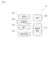
入力装置16は、たとえば、ドライバーの手動操作による入力が可能なボタンスイッチ、ディスプレイ画面上に配置されたタッチパネル、又はドライバーの音声による入力が可能なマイクなどの装置である。本実施形態では、ドライバーが入力装置16を操作することで、提示装置15により提示された提示情報に対する設定情報を入力することができる。図2は、本実施形態の入力装置16の一部を示す正面図であり、ステアリングホイールのスポーク部などに配置されたボタンスイッチ群からなる一例を示す。図示する入力装置16は、制御装置18が備える自律速度制御機能及び自律操舵制御機能のON/OFFを設定する際に使用するボタンスイッチであり、メインスイッチ161と、リジューム・アクセラレートスイッチ162と、セット・コーストスイッチ163と、キャンセルスイッチ164と、車間調整スイッチ165と、車線変更支援スイッチ166とを備える。
The
メインスイッチ161は、制御装置18の自律速度制御機能及び自律操舵制御機能を実現するシステムの電源をON/OFFするスイッチである。リジューム・アクセラレートスイッチ162は、自律速度制御機能の作動をOFFしたのちOFF前の設定速度で自律速度制御機能を再開したり、設定速度を上げたり、先行車に追従して停車したのち再発進させたりするスイッチである。セット・コーストスイッチ163は、走行時の速度で自律速度制御機能を開始したり、設定速度を下げたりするスイッチである。キャンセルスイッチ164は、自律速度制御機能をOFFするスイッチである。車間調整スイッチ165は、先行車との車間距離を設定するためのスイッチであり、たとえば短距離・中距離・長距離といった複数段の設定から1つを選択するスイッチである。車線変更支援スイッチ166は、制御装置18が車線変更の開始をドライバーに確認した場合に車線変更の開始を指示する(承諾する)ためのスイッチである。
The
なお、図2に示すボタンスイッチ群以外にも、方向指示器やその他の車載機器14のスイッチを入力装置16として用いることもでき、制御装置18が自動で車線変更を行うか否かの問い合わせに対して、ドライバーが方向指示器のスイッチをオンにすることで、車線変更の承諾乃至許可を入力する構成とすることもできる。なお、入力装置16により入力された設定情報は、制御装置18に出力される。
In addition to the group of button switches shown in FIG. 2, a direction indicator or other switches of the vehicle-mounted device 14 can also be used as the
駆動制御装置17は、自車両の走行を制御する。たとえば、駆動制御装置17は、自律速度制御機能により、自車両が設定速度で定速走行したり、先行車に追従走行したりする場合には、自車両が設定速度となるように、又は先行車が存在する場合には自車両と先行車との車間距離が一定距離となるように、加減速度および走行速度を実現するための駆動機構の動作(エンジン自動車にあっては内燃機関の動作、電気自動車系にあっては走行用モータの動作を含み、ハイブリッド自動車にあっては内燃機関と走行用モータとのトルク配分も含む)およびブレーキ動作を制御する。また、自律操舵制御機能により、自車両が走行する車線(以下、自車線ともいう。)のレーンマーカを検出し、自車両が自車線内の、たとえば中央を走行するように、自車両の幅員方向における走行位置を制御するレーンキープ制御を行う場合、車線変更支援機能、追い越し支援機能又はルート走行支援機能により、自車両が先行車の追い越しや走行方向の変更などの自動車線変更制御を行う場合、右左折支援機能により、交差点などにおいて右折又は左折する走行制御を行う場合には、加減速度および走行速度を実現するための駆動機構の動作並びにブレーキ動作に加えて、ステアリングアクチュエータの動作を制御することで、自車両の操舵制御を実行する。なお、駆動制御装置17は、後述する制御装置18の指示により自車両の走行を制御する。また、駆動制御装置17による走行制御方法として、その他の公知の方法を用いることもできる。 The drive control device 17 controls running of the host vehicle. For example, the drive control device 17 uses the autonomous speed control function to control the speed of the own vehicle to the set speed or the speed when the own vehicle runs at a set speed or follows the preceding vehicle. When a vehicle is present, the operation of the drive mechanism (in the case of a combustion engine vehicle, the operation of the internal combustion engine, the operation of the internal combustion engine, In an electric vehicle system, it includes the operation of the driving motor, and in a hybrid vehicle, it also includes torque distribution between the internal combustion engine and the driving motor) and brake operation. In addition, the autonomous steering control function detects the lane marker of the lane in which the vehicle is traveling (hereinafter also referred to as the own lane), and controls the width direction of the own vehicle so that the own vehicle runs in the center of the own lane, for example. When performing lane-keeping control to control the driving position in the lane change support function, overtaking support function, or route driving support function, when the own vehicle performs automatic lane change control such as overtaking the preceding vehicle or changing the driving direction, When the right/left turn support function is used to control driving to turn right or left at an intersection, etc., control the operation of the steering actuator in addition to the operation of the drive mechanism and brake operation to achieve acceleration/deceleration and travel speed. , the steering control of the own vehicle is executed. The drive control device 17 controls the running of the own vehicle according to instructions from the control device 18, which will be described later. Other known methods can also be used as the travel control method by the drive control device 17 .
制御装置18は、自車両の走行を制御するためのプログラムを格納したROM(Read Only Memory)と、このROMに格納されたプログラムを実行するCPU(Central Processing Unit)と、アクセス可能な記憶装置として機能するRAM(Random Access Memory)とから構成される。なお、動作回路としては、CPU(Central Processing Unit)に代えて又はこれとともに、MPU(Micro Processing Unit)、DSP(Digital Signal Processor)、ASIC(Application Specific Integrated Circuit)、FPGA(Field Programmable Gate Array)などを用いることができる。 The control device 18 includes a ROM (Read Only Memory) that stores a program for controlling the running of the vehicle, a CPU (Central Processing Unit) that executes the program stored in the ROM, and an accessible storage device. It consists of functional RAM (random access memory). In addition, as the operation circuit, instead of or together with the CPU (Central Processing Unit), MPU (Micro Processing Unit), DSP (Digital Signal Processor), ASIC (Application Specific Integrated Circuit), FPGA (Field Programmable Gate Array), etc. can be used.
制御装置18は、ROMに格納されたプログラムをCPUにより実行することにより、自車両の走行状態に関する情報を取得する走行情報取得機能と、自車両の走行シーンを判定する走行シーン判定機能と、自車両の走行速度及び/又は操舵を自律制御する自律走行制御機能(自車両の走行速度を自律制御する自律速度制御機能と、自車両の操舵を自律制御する自律操舵制御機能を含む。)を実現する。以下、制御装置18が備える各機能について説明する。 The control device 18 has a running information acquisition function for acquiring information about the running state of the own vehicle, a running scene determination function for determining the running scene of the own vehicle, and a running scene determining function for determining the running scene of the own vehicle. Realization of an autonomous driving control function that autonomously controls the traveling speed and/or steering of the vehicle (including an autonomous speed control function that autonomously controls the traveling speed of the own vehicle and an autonomous steering control function that autonomously controls the steering of the own vehicle) do. Each function of the control device 18 will be described below.
制御装置18の走行情報取得機能は、自車両の走行状態に関する走行情報を取得する機能である。たとえば、制御装置18は、走行情報取得機能により、センサ11に含まれる前方カメラおよび後方カメラにより撮像された車両外部の画像情報や、前方レーダー、後方レーダー、および側方レーダーによる検出結果を、走行情報として取得する。また、制御装置18は、走行情報取得機能により、センサ11に含まれる車速センサにより検出された自車両の車速情報や、車内カメラにより撮像されたドライバーの顔の画像情報も走行情報として取得する。 The travel information acquisition function of the control device 18 is a function of acquiring travel information regarding the travel state of the own vehicle. For example, the control device 18 uses the driving information acquisition function to obtain image information of the outside of the vehicle captured by the front camera and the rear camera included in the sensor 11, and the detection results of the front radar, the rear radar, and the side radar. Get it as information. In addition, the control device 18 also acquires vehicle speed information of the own vehicle detected by the vehicle speed sensor included in the sensor 11 and image information of the driver's face captured by the in-vehicle camera as driving information by the driving information acquisition function.
さらに、制御装置18は、走行情報取得機能により、自車両の現在位置の情報を走行情報として自車位置検出装置12から取得する。また、制御装置18は、走行情報取得機能により、カーブ路及びそのカーブの大きさ(たとえば曲率又は曲率半径)、合流地点、分岐地点、料金所、車線数の減少位置、サービスエリア(SA)/パーキングエリア(PA)などの位置情報を走行情報として地図データベース13から取得する。加えて、制御装置18は、走行情報取得機能により、ドライバーによる車載機器14の操作情報を、走行情報として車載機器14から取得する。 Furthermore, the control device 18 acquires the current position information of the own vehicle from the own vehicle position detection device 12 as the traveling information by the traveling information acquisition function. In addition, the control device 18 uses the traveling information acquisition function to obtain a curved road and its curve size (for example, curvature or radius of curvature), merging point, branching point, toll gate, position where the number of lanes decreases, service area (SA)/ Location information such as a parking area (PA) is acquired from the map database 13 as travel information. In addition, the control device 18 acquires operation information of the in-vehicle device 14 by the driver from the in-vehicle device 14 as travel information using the travel information acquisition function.
制御装置18の走行シーン判定機能は、制御装置18のROMに記憶されたテーブルを参照して、自車両が走行している走行シーンを判定する機能である。制御装置18のROMに記憶されたテーブルには、たとえば車線変更や追い越しに適した走行シーンとその判定条件が、走行シーンごとに記憶されている。制御装置18は、走行シーン判定機能により、ROMに記憶されたテーブルを参照して、自車両の走行シーンが、たとえば車線変更や追い越しに適した走行シーンであるか否かを判定する。 The driving scene determination function of the control device 18 refers to a table stored in the ROM of the control device 18 to determine the driving scene in which the host vehicle is running. A table stored in the ROM of the control device 18 stores, for example, driving scenes suitable for changing lanes and overtaking and determination conditions for each driving scene. The controller 18 uses the driving scene determination function to refer to the table stored in the ROM and determines whether or not the driving scene of the own vehicle is suitable for, for example, changing lanes or overtaking.
たとえば、「先行車への追いつきシーン」の判定条件として、「前方に先行車が存在」、「先行車の車速<自車両の設定車速」、「先行車への到達が所定時間以内」、および「車線変更の方向が車線変更禁止条件になっていない」の4つの条件が設定されているとする。この場合、制御装置18は、走行シーン判定機能により、たとえば、センサ11に含まれる前方カメラや前方レーダーによる検出結果、車速センサにより検出された自車両の車速、および自車位置検出装置12による自車両の位置情報などに基づいて、自車両が上記条件を満たすか否かを判断し、上記条件を満たす場合に、自車両が「先行車への追いつきシーン」であると判定する。 For example, the criteria for catching up with the preceding vehicle are: ``preceding vehicle exists in front'', ``vehicle speed of leading vehicle < vehicle speed set for own vehicle'', ``arrive at preceding vehicle within a predetermined time'', and Suppose that four conditions are set, that is, "the lane change direction is not a lane change prohibition condition." In this case, the control device 18 uses the driving scene determination function to determine, for example, the detection results of the front camera and front radar included in the sensor 11, the vehicle speed of the vehicle detected by the vehicle speed sensor, and the vehicle speed detected by the vehicle position detection device 12. Based on the positional information of the vehicle, it is determined whether or not the vehicle satisfies the above condition, and if the condition is satisfied, the vehicle is judged to be in a "catch-up scene with the preceding vehicle".
制御装置18の自律走行制御機能は、自車両の走行をドライバーの操作に依ることなく自律制御する機能であり、自車両の走行速度を自律制御する自律速度制御機能と、自車両の操舵を自律制御する自律操舵制御機能とを含む。以下、本実施形態の自律速度制御機能と自律操舵制御機能を説明する。 The autonomous driving control function of the control device 18 is a function for autonomously controlling the driving of the own vehicle without depending on the driver's operation. Autonomous steering control function to control. The autonomous speed control function and the autonomous steering control function of this embodiment will be described below.
《自律速度制御機能》
自律速度制御機能は、先行車を検出しているときは、ドライバーが設定した車速を上限にして、車速に応じた車間距離を保つように車間制御を行いつつ先行車に追従走行する機能である。一方、自律速度制御機能は、先行車を検出していない場合はドライバーが設定した車速で定速走行する機能である。前者を車間制御、後者を定速制御ともいう。なお、走行情報取得機能により、走行車線の制限速度を検出した場合、制限速度標識の速度を自動的に設定車速にする機能を含んでもよい。《Autonomous speed control function》
Autonomous speed control is a function that, when a preceding vehicle is detected, follows the preceding vehicle while controlling the distance between the vehicles so that the vehicle speed is set by the driver as the upper limit. . On the other hand, the autonomous speed control function is a function that keeps the vehicle at a constant speed set by the driver when no preceding vehicle is detected. The former is also called inter-vehicle control, and the latter is called constant speed control. It should be noted that, when the speed limit of the driving lane is detected by the driving information acquisition function, the speed limit sign may be automatically set to the set vehicle speed.
自律速度制御機能を作動させるには、まずドライバーが、図2に示す入力装置16のリジューム・アクセラレートスイッチ162又はセット・コーストスイッチ163を操作して、所望の走行速度を入力する。たとえば、自車両が70km/hで走行中にセット・コーストスイッチ163を押すと、現在の走行速度がそのまま設定されるが、ドライバーが所望する速度が80km/hであるとすると、リジューム・アクセラレートスイッチ162を複数回押して、設定速度を上げればよい。逆にドライバーが所望する速度が60km/hであるとすると、セット・コーストスイッチ163を複数回押して、設定速度を下げればよい。また、ドライバーが所望する車間距離は、図2に示す入力装置16の車間調整スイッチ165を操作し、たとえば短距離・中距離・長距離といった複数段の設定から1つを選択すればよい。
To activate the autonomous speed control function, the driver first operates the resume/accelerate
定速制御は、ドライバーにより設定された走行速度を維持するように、車速センサによる車速データをフィードバックしながら、駆動制御装置17によりエンジンやブレーキなどの駆動機構の動作を制御するものである。この定速制御は、自車両の前方の障害物を検出する前方レーダーなどのセンサ11を用いて自車両が走行する車線の前方に先行車が存在しないことを検出しながら実行する。 In constant speed control, the drive control device 17 controls the operation of drive mechanisms such as the engine and brakes while feeding back vehicle speed data from a vehicle speed sensor so as to maintain the running speed set by the driver. This constant speed control is executed while detecting that there is no preceding vehicle ahead of the lane in which the vehicle is traveling using a sensor 11 such as a front radar that detects obstacles ahead of the vehicle.
車間制御は、ドライバーにより設定された走行速度を上限にして、ドライバーにより設定された車間距離を維持するように、センサ11(前方レーダー)による車間距離データをフィードバックしながら、駆動制御装置17によりエンジンやブレーキなどの駆動機構の動作を制御するものである。この車間制御は、自車両の前方の障害物を検出する前方レーダーなどのセンサ11を用いて、自車両が走行する車線の前方に先行車(自車両の直前の車両)が存在することとその車間距離を検出しながら、実行する。なお、車間制御で走行中に先行車が停止した場合は、先行車に続いて自車も停止し、自車が停止した後、たとえば30秒以内に先行車が発進すると、自車も発進し、再び車間制御による追従走行を開始する。自車が30秒を超えて停止している場合は、先行車が発進しても自動で発進せず、先行車が発進した後、リジューム・アクセラレートスイッチ162を押すか又はアクセルペダルを踏むと、再び車間制御による追従走行を開始する。 The inter-vehicle distance control keeps the driving speed set by the driver as the upper limit and maintains the inter-vehicle distance set by the driver. It controls the operation of the drive mechanism such as the brake and the brake. This inter-vehicle distance control uses a sensor 11 such as a front radar for detecting obstacles in front of the vehicle to detect the presence of a preceding vehicle (vehicle immediately in front of the vehicle) in the lane in which the vehicle is traveling and Execute while detecting the inter-vehicle distance. If the preceding vehicle stops while driving under the inter-vehicle distance control, the own vehicle will stop following the preceding vehicle. , the follow-up running is started again by the vehicle-to-vehicle distance control. If the own vehicle has been stopped for more than 30 seconds, it will not start automatically even if the preceding vehicle starts moving. , the follow-up running is started again by the vehicle-to-vehicle distance control.
本実施形態の自律速度制御機能には、上述した定速制御や車間制御の他、カーブ路を走行する際に、カーブの大きさ(カーブの曲率又は曲率半径など)に応じた速度で走行できるように速度制御するカーブ路速度制御機能を含む。このカーブ路速度制御機能は、自律速度制御機能が作動している場合にのみ、カーブ路を走行する際の速度を制御する機能である。図3は、入力装置16の他の一部を示す正面図、図4は、制御装置18に記憶されたカーブ路の曲率半径に対する設定速度を示す制御マップである。本実施形態のカーブ路速度制御機能は、予めその機能を作動するか否かのON/OFFが設定可能とされ、図3に示すように、たとえばナビゲーション装置のディスプレイの一つの表示画面167を用いて、ONボタン168又はOFFボタン169のいずれかを入力することができるようにされている。
The autonomous speed control function of this embodiment includes the above-described constant speed control and inter-vehicle distance control, and when traveling on a curved road, it is possible to travel at a speed according to the size of the curve (curvature or radius of curvature, etc.). Including curve road speed control function to control speed. This curve road speed control function is a function that controls the speed when traveling on a curve road only when the autonomous speed control function is in operation. FIG. 3 is a front view showing another part of the
この表示画面167において、ONボタン168を入力すると、本実施形態のカーブ路速度制御機能が有効に作動し、OFFボタン169を入力するか又は設定システムを初期化しない限り、カーブ路速度制御機能のONが保持される。逆に表示画面167において、OFFボタン169を入力すると、本実施形態のカーブ路速度制御機能が無効とされ、ONボタン168を入力しない限り、カーブ路速度制御機能のOFFが保持される。なお、特に限定されないが、初期状態におけるカーブ路速度制御機能の設定はONとする。
When the
本実施形態のカーブ路速度制御機能は、自車両の前方にカーブ路を検出したら、カーブの大きさに応じた速度で走行できるように速度制御する機能であり、自律速度制御としてドライバーにより設定された速度ではなく、予め準備された制御マップから抽出される速度で走行する。たとえば、ドライバーによる設定速度が80km/hと高速である場合、急カーブを走行すると、走行感覚としての不安感又は違和感を覚えることになるので、カーブ路を走行する間は、車両の設定速度をたとえば70km/hと低く設定する。すなわち、ドライバーにより設定された走行速度が、図4に示す制御マップから抽出される設定速度を超える場合には、当該制御マップから抽出される設定速度を上限にして、車両の走行速度を制御する。 The curved road speed control function of this embodiment is a function that, when a curved road is detected in front of the vehicle, controls the speed so that the vehicle can travel at a speed corresponding to the size of the curve, and is set by the driver as autonomous speed control. It runs at a speed extracted from a control map prepared in advance, rather than at a speed determined in advance. For example, if the speed set by the driver is as high as 80 km/h, driving on a sharp curve will cause a feeling of uneasiness or discomfort in driving. For example, it is set as low as 70 km/h. That is, when the running speed set by the driver exceeds the set speed extracted from the control map shown in FIG. 4, the running speed of the vehicle is controlled with the set speed extracted from the control map as the upper limit. .
自車両の前方にカーブ路があるか否かは、たとえばナビゲーション装置に目的地を入力し、当該目的地までのルートを設定した場合に、地図データベース13を参照して、当該ルート上にカーブ路としての地図データがあるかどうかを判定することにより検出される。カーブの大きさは、カーブの曲率又は曲率半径のデータを地図データベース13から抽出し、これを図4に示す制御マップに入力することで、当該カーブ路を走行する際の走行速度を抽出する。上述したように、カーブ路の曲率半径が小さくなると車両に作用する遠心力(横G)が大きくなり、走行感覚としての不安感又は違和感を覚えることになるので、本実施形態では、図4に示すように、カーブ路の曲率半径が小さくなるほど車両の設定速度を低くする。 Whether or not there is a curve ahead of the vehicle can be determined by referring to the map database 13 when a destination is entered into the navigation device and a route to the destination is set. It is detected by determining whether there is map data as . As for the size of the curve, data on the curvature or radius of curvature of the curve is extracted from the map database 13 and input into the control map shown in FIG. As described above, when the radius of curvature of the curved road becomes smaller, the centrifugal force (lateral G) acting on the vehicle becomes larger, and the driver feels uneasy or uncomfortable while driving. As shown, the smaller the radius of curvature of the curved road, the lower the set speed of the vehicle.
本実施形態のカーブ路速度制御機能は、図3に示す表示画面167によるON/OFF設定に従って有効又は無効とされるが、2つの例外が設定されている。すなわち、図3に示す表示画面167によるカーブ路速度制御機能がOFFの設定であっても、自律速度制御(車間制御又は定速制御)が実行され、且つ後述する自律操舵制御が実行されている場合には、制御装置18のソフトウェアによりカーブ路速度制御機能を作動する。自律操舵制御により急カーブなどを走行する場合に、ドライバーにより設定された走行速度が高速であるときは、曲がり切れずに自律走行を中断せざるを得ないおそれがあるからである。
The curve road speed control function of this embodiment is enabled or disabled according to the ON/OFF setting on the
第2の例外は、図3に示す表示画面167によるカーブ路速度制御機能がONの設定であっても、自律操舵制御機能の設定がOFFであり、自律速度制御機能の車間制御により先行車に追従走行している場合は、カーブ路速度制御機能を作動させない(無効にする)。ドライバーのハンドル操作に従い、先行車を追従しているので、カーブ路速度制御を働かせて速度を落とさなくても、不安感や違和感を覚えることなくカーブを曲がれるからである。
The second exception is that even if the curve road speed control function is set to ON on the
《自律操舵制御機能》
自律操舵制御機能は、ステアリングアクチュエータの動作を制御することで、自車両の操舵制御を実行する機能である。車線のたとえば中央付近を走行するようにステアリングを制御して、ドライバーのハンドル操作を支援するレーンキープ機能(車線幅員方向維持機能)、ドライバーがウィンカーレバーを操作するとステアリングを制御し、車線変更に必要なハンドル操作を支援する車線変更支援機能、設定車速よりも遅い車両を前方に検出すると、表示によりドライバーに追い越し操作を行うか確認し、ドライバーが承諾スイッチを操作した場合、ステアリングを制御し追い越し操作を支援する追い越し支援機能、ドライバーがナビゲーション装置などに目的地を設定している場合には、ルートに従って走行するために必要な車線変更地点に到達すると、表示によりドライバーに車線変更を行うか確認し、ドライバーが承諾スイッチを操作した場合、ステアリングを制御し車線変更を支援するルート走行支援機能などが含まれる。《Autonomous steering control function》
The autonomous steering control function is a function that executes steering control of the own vehicle by controlling the operation of the steering actuator. Lane keep function (lane width direction maintenance function) that controls the steering so that the vehicle runs in the center of the lane, for example, and assists the driver in handling the steering wheel. When a vehicle ahead that is slower than the set speed is detected, the driver is asked if he or she wants to overtake. If the driver has set a destination in the navigation device, etc., the display will ask the driver if they would like to change lanes when they arrive at the lane change point required to follow the route. , When the driver operates the consent switch, it includes a route driving support function that controls the steering and supports lane changes.
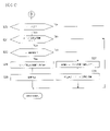
図5は、制御装置18に確立された各機能の状態遷移を示すブロック図である。同図に示すシステムとは、制御装置18により実現される自律走行制御システムを意味する。同図に示すシステムOFFの状態から、図2のメインスイッチ161をONすると、当該システムがスタンバイ状態となる。このスタンバイ状態から、図2のセット・コーストスイッチ163又はリジューム・アクセラレートスイッチ162をONすることで、自律速度制御が立ち上がる。これにより、上述した定速制御又は車間制御が開始し、ドライバーはハンドルを操作するだけで、アクセルやブレーキを踏むことなく、自車両を走行させることができる。
FIG. 5 is a block diagram showing state transitions of each function established in the control device 18. As shown in FIG. The system shown in the figure means an autonomous driving control system realized by the control device 18 . When the
自律速度制御を実行中に、図5の条件(1)が成立すると自律操舵制御・ハンズオンモードのレーンキープモードに遷移する。この条件(1)としては、特に限定されないが、自車両の両側のレーンマーカを検出していること、ドライバーがハンドルを持っていること、車線の中央付近を走行していること、ウィンカーが作動していないこと、ワイパーが高速(HI)で作動していないこと、高精度地図がある場合、前方約200m以内に料金所、出口、合流、交差点、車線数減少地点がないこと、といった全ての条件が成立することなどを例示できる。なお、ハンズオンモードとは、ドライバーがハンドルを持っていないと自律操舵制御が作動しないモードをいい、ハンズオフモードとは、ドライバーがハンドルから手を離しても自律操舵制御が作動するモードをいう。 If the condition (1) in FIG. 5 is established while the autonomous speed control is being executed, the lane keeping mode of the autonomous steering control/hands-on mode is entered. This condition (1) is not particularly limited, but the lane markers on both sides of the own vehicle are detected, the driver is holding the steering wheel, the driver is driving near the center of the lane, and the turn signal is activated. wipers are not operating at high speed (HI), and if there is a high-definition map, there are no toll booths, exits, junctions, intersections, or lane reduction points within about 200m ahead. can be exemplified. Hands-on mode is a mode in which autonomous steering control is not activated unless the driver is holding the steering wheel, and hands-off mode is a mode in which autonomous steering control is activated even if the driver releases the steering wheel.
自律操舵制御・ハンズオンモードのレーンキープモードを実行中に、図5の条件(2)が成立すると、自律操舵制御・ハンズオフモードのレーンキープモードに遷移する。この条件(2)として、特に限定されないが、自車両が自動車専用道を走行していること、対向車線と構造的に分離された道路を走行していること、高精度地図がある道路を走行していること、制限速度以下の車速で走行していること、GPS信号が有効であること、ドライバーがハンドルを持っていること、ドライバーが前を向いていること、前方約800m以内に料金所、出口、合流、交差点、車線数減少地点がないこと、前方約500m以内に100R以下の急カーブがないこと、トンネル入り口から500mを超えたトンネル内走行していないこと、アクセルペダルが踏まれていないこと、といった全ての条件が成立することなどを例示できる。 If the condition (2) in FIG. 5 is satisfied while the lane keeping mode of the autonomous steering control/hands-on mode is being executed, the lane keeping mode of the autonomous steering control/hands-off mode is entered. Conditions (2) include, but are not limited to, the vehicle traveling on a motorway, traveling on a road structurally separated from oncoming traffic, and traveling on a road with a high-precision map. the vehicle speed is below the speed limit; the GPS signal is valid; the driver is holding the steering wheel; the driver is facing forward; , There are no exits, confluences, intersections, or points where the number of lanes decreases. There are no sharp curves of 100R or less within about 500m ahead. It can be exemplified that all conditions such as that there is no such condition are satisfied.
逆に、自律操舵制御・ハンズオフモードのレーンキープモードを実行中に、図5の条件(3)が成立すると、自律操舵制御・ハンズオンモードのレーンキープモードに遷移する。この条件(3)として、特に限定されないが、自車両が自動車専用道以外の道路を走行していること、対面通行区間を走行していること、高精度地図がない道路を走行していること、制限速度を超えた車速で走行していること、GPS信号が受信できなくなったこと、前方注視警報が作動した後、ドライバーが5秒以内に前を向かなかったこと、ドライバーモニターカメラで運転者を検知できなくなったこと、前方約800m先に料金所、出口、合流、車線数減少のいずれかがあること、車速が約40km/h未満で走行している場合、前方約200m以内に100R以下の急カーブがあること、車速が約40km/h以上で走行している場合、前方約200m以内に170Rの以下急カーブがあること、トンネル入り口から500mを超えたトンネル内を走行していること、ドライバーがハンドルを持って、アクセルペダルを踏んだこと、接近警報が作動したこと、といったいずれかの条件が成立することなどを例示できる。 Conversely, if the condition (3) in FIG. 5 is satisfied while the lane keeping mode of the autonomous steering control/hands-off mode is being executed, the lane keeping mode of the autonomous steering control/hands-on mode is entered. Conditions (3) include, but are not limited to, that the vehicle is traveling on a road other than a motorway, traveling on a two-way traffic section, and traveling on a road that does not have a high-precision map. , the vehicle was traveling at a speed exceeding the speed limit, the GPS signal could not be received, the driver did not turn forward within 5 seconds after the forward look warning was activated, and the driver was driving with a driver monitor camera. If there is a tollgate, exit, merging, or decrease in the number of lanes about 800m ahead, and if the vehicle speed is less than about 40km/h, 100R within about 200m ahead If the vehicle is traveling at a speed of approximately 40km/h or more, there is a sharp curve of 170R or less within approximately 200m ahead of the vehicle, and the vehicle is traveling in a tunnel more than 500m from the tunnel entrance. For example, the driver holds the steering wheel and depresses the accelerator pedal, or the proximity alarm is activated.
自律操舵制御・ハンズオフモードのレーンキープモードを実行中に、図5の条件(4)が成立すると、自律操舵制御を中止して自律速度制御に遷移する。この条件(4)として、特に限定されないが、自車両の両側のレーンマーカを一定時間検出しなくなったこと、ドライバーがハンドル操作をしたこと、ワイパーが高速(HI)で作動したこと、といったいずれかの条件が成立することなどを例示できる。また、自律操舵制御・ハンズオフモードのレーンキープモードを実行中に、図5の条件(5)が成立すると、自律操舵制御及び自律速度制御を中止してスタンバイ状態に遷移する。この条件(5)として、特に限定されないが、ドライバーがブレーキを操作したこと、ドライバーが図2のキャンセルスイッチ164を操作したこと、自車両のドアが開いたこと、運転席のシートベルトが解除されたこと、着座センサでドライバーが運転席からいなくなったことを検知したこと、セレクトレバーが「D」または「M」以外になったこと、パーキングブレーキが作動したこと、車両の横滑り防止装置がOFFになったこと、横滑り防止装置が作動したこと、スノーモードがONにされたこと、エマージェンシーブレーキが作動したこと、車速制御により車両が停止した後、停止状態が約3分継続したこと、フロントカメラが、汚れ、逆光、雨・霧などで対象物を正しく認識できないといった視界不良を検出したこと、フロントレーダが遮蔽、電波障害を検出したこと、フロントレーダが軸ずれを検出したこと、サイドレーダが遮蔽、電波障害を検出したこと、サイドレーダが軸ずれを検出したこと、といったいずれかの条件が成立することなどを例示できる。
If the condition (4) in FIG. 5 is satisfied while the lane keeping mode of the autonomous steering control/hands-off mode is being executed, the autonomous steering control is stopped and the autonomous speed control is started. Conditions (4) include, but are not limited to, any of the following: lane markers on both sides of the vehicle have not been detected for a certain period of time; the driver has operated the steering wheel; or the wipers have been operated at high speed (HI). For example, the establishment of a condition can be exemplified. Further, when the condition (5) in FIG. 5 is satisfied while the lane keeping mode of the autonomous steering control/hands-off mode is being executed, the autonomous steering control and the autonomous speed control are stopped and the vehicle shifts to the standby state. Conditions (5) include, but are not limited to, the driver operating the brake, the driver operating the cancel
自律操舵制御・ハンズオンモードを実行中に、図5の条件(6)が成立すると、自律操舵制御を中止して自律速度制御に遷移する。この条件(6)として、特に限定されないが、自車両の両側のレーンマーカを検出しなくなったこと、ドライバーがハンドル操作をしたこと、ドライバーがウィンカーを操作したこと、ワイパーが高速(HI)で作動したこと、高精度地図がある場合に料金所区間になったこと、フロントカメラが、汚れ、逆光、雨・霧などで対象物を正しく認識できない視界不良を検出したこと、といったいずれかの条件が成立することなどを例示できる。また、自律操舵制御・ハンズオンモードを実行中に、図5の条件(7)が成立すると、自律操舵制御及び自律速度制御を中止してスタンバイ状態に遷移する。この条件(7)として、特に限定されないが、ドライバーがブレーキを操作したこと、ドライバーが図2のキャンセルスイッチ164を操作したこと、自車両のドアが開いたこと、運転席のシートベルトが解除されたこと、着座センサでドライバーが運転席からいなくなったことを検知したこと、セレクトレバーが「D」または「M」以外になったこと、パーキングブレーキが作動したこと、車両の横滑り防止装置がOFFになったこと、横滑り防止装置が作動したこと、スノーモードがONにされたこと、エマージェンシーブレーキが作動したこと、車速制御により車両が停止した後、停止状態が約3分継続したこと、フロントレーダが遮蔽、電波障害を検出したこと、フロントレーダが軸ずれを検出したこと、といったいずれかの条件が成立することなどを例示できる。
If the condition (6) in FIG. 5 is satisfied while the autonomous steering control/hands-on mode is being executed, the autonomous steering control is stopped and the transition is made to the autonomous speed control. Conditions (6) include, but are not limited to, the lane markers on both sides of the vehicle are no longer detected, the driver has operated the steering wheel, the driver has operated the turn signals, and the wipers are operating at high speed (HI). , when there is a high-definition map, the toll gate section is reached, or when the front camera detects poor visibility that makes it impossible to correctly recognize the target object due to dirt, backlight, rain, fog, etc. Examples include: Further, when the condition (7) in FIG. 5 is established while the autonomous steering control/hands-on mode is being executed, the autonomous steering control and the autonomous speed control are stopped and the state is changed to the standby state. Conditions (7) include, but are not limited to, the driver operating the brake, the driver operating the cancel
自律速度制御を実行中に、図5の条件(8)が成立すると、スタンバイ状態に遷移する。この条件(8)として、特に限定されないが、ドライバーがブレーキを操作したこと、ドライバーが図2のキャンセルスイッチ164を操作したこと、自車両のドアが開いたこと、運転席のシートベルトが解除されたこと、着座センサでドライバーが運転席からいなくなったことを検知したこと、セレクトレバーが「D」または「M」以外になったこと、パーキングブレーキが作動したこと、車両の横滑り防止装置がOFFになったこと、横滑り防止装置が作動したこと、スノーモードがONにされたこと、エマージェンシーブレーキが作動したこと、車速制御により車両が停止した後、停止状態が約3分継続したこと、フロントレーダが遮蔽、電波障害を検出したこと、フロントレーダが軸ずれを検出したこと、といったいずれかの条件が成立することなどを例示できる。
If the condition (8) in FIG. 5 is satisfied while the autonomous speed control is being executed, the state transitions to the standby state. Conditions (8) include, but are not limited to, the driver operating the brake, the driver operating the cancel
自律操舵制御・ハンズオフモードのレーンキープモードを実行中に、図5の条件(9)が成立すると、自律操舵制御・ハンズオンモードのレーンチェンジモードに遷移する。この条件(8)として、特に限定されないが、システムがレーンチェンジを提案したときに、ドライバーが図2の車線変更支援スイッチ166を押したこと、ドライバーがウィンカーを操作したこと、といったいずれかの条件が成立することなどを例示できる。
If the condition (9) in FIG. 5 is established while the lane keep mode of the autonomous steering control/hands-off mode is being executed, the lane change mode of the autonomous steering control/hands-on mode is entered. This condition (8) is not particularly limited, but can be any condition such as the driver pressing the lane
自律操舵制御・ハンズオンモードのレーンチェンジモードを実行中に、図5の条件(10)が成立すると、自律操舵制御・ハンズオンモードのレーンキープモードに遷移する。この条件(10)として、特に限定されないが、車線変更操作(以下LCP)開始前に、制限速度を超えたこと、LCP開始前に、ドライバーが、ハンドルを持って、アクセルペダルを踏んだこと、前方に遅い車がいた場合の車線変更提案中に車線変更支援スイッチ166を押した後、10秒以内にLCPが開始できなかったこと、ルートに従って走行するための車線変更提案中に車線変更支援スイッチ166を押した後、LCPを開始できず分岐に近づきすぎてしまったこと、LCP作動後、5秒以内に実際の車線変更操縦(以下、LCM)を開始できなかったこと、LCPを開始し、LCMを開始する前に車速が約50km/hを下回ったこと、LCPが作動した後、LCMを開始する前に車線変更に必要な隣車線のスペースがなくなったこと、LCM開始前にドライバーがキャンセル操作を行ったこと、LCM開始前にレーンマーカが非検知となったこと、LCM開始前に、車線変更する方向に隣接車線がない、または、前方一定距離内にその隣接車線がなくなると判断したこと、LCM開始前に、前方一定距離内に曲率半径250m以下のカーブがあると判断したこと、LCM開始前に、前方一定距離内に区分線の種類がその隣接車線への車線変更禁止している区間があると判断したこと、LCM開始前に、サイドレーダが遮蔽、電波障害を検出したこと、LCM開始前に、サイドレーダが軸ズレを検出したこと、ハンズオン警報が作動したこと(LCPが作動した後、約2秒以内にドライバーがハンドルを持たなかった、前方に遅い車がいた場合の車線変更提案中に車線変更支援スイッチ166を押した後、約2秒以内にドライバーがハンドルを持たなかった、ルートに従って走行するための車線変更提案中に車線変更支援スイッチ166を押したのち、約2秒以内にドライバーがハンドルを持たなかったといういずれかの条件にて成立)、ドライバーがウィンカーを消したこと、LCPが完了したこと、といったいずれかの条件が成立することなどを例示できる。
If the condition (10) in FIG. 5 is satisfied while the lane change mode of the autonomous steering control/hands-on mode is being executed, the lane transition is made to the lane keep mode of the autonomous steering control/hands-on mode. Conditions (10) include, but are not limited to, exceeding the speed limit before starting the lane change operation (LCP), the driver holding the steering wheel and stepping on the accelerator pedal before starting the LCP, LCP could not be started within 10 seconds after pushing the lane
なお、自律操舵制御・ハンズオフモード、自律操舵制御・ハンズオンモード、自律速度制御、スタンバイ状態のいずれかの状態でメインスイッチ161をOFFすると、システムOFFとなる。
If the
次に、図6A~図6Cを参照して、本実施形態に係る走行制御処理について説明する。図6A~図6Cは、本実施形態に係る走行制御処理を示すフローチャートである。なお、以下に説明する走行制御処理は、制御装置18により所定時間間隔で実行される。また、以下においては、制御装置18の自律走行制御機能により、自律速度制御と自律操舵制御が実行され、自車両が、ドライバーが設定した速度で車線内を走行するように、自車両の幅員方向における走行位置を制御するレーンキープ制御が行われている間に、カーブ路を走行するものとして説明する。 Next, traveling control processing according to the present embodiment will be described with reference to FIGS. 6A to 6C. 6A to 6C are flowcharts showing travel control processing according to the present embodiment. The travel control process described below is executed by the control device 18 at predetermined time intervals. In addition, in the following description, autonomous speed control and autonomous steering control are executed by the autonomous driving control function of the control device 18, and the width direction of the vehicle is controlled so that the vehicle runs within the lane at the speed set by the driver. It is assumed that the vehicle travels on a curved road while lane keep control is being performed to control the travel position of the vehicle.
まず、図6AのステップS1にて、制御装置18のメインスイッチ161がONされているか否かを判定し、メインスイッチ161がOFFである場合はONになるまでステップS1を繰り返す。メインスイッチ161がONである場合はステップS2に進み、ドライバーにより走行速度が設定されているか否かを判定する。走行速度が設定されていない場合はステップS1へ戻り、走行速度が設定されるまでステップS1及びS2を繰り返す。なお、ドライバーによる走行速度の設定は、ドライバーが、図2に示す入力装置16のリジューム・アクセラレートスイッチ162又はセット・コーストスイッチ163を操作して、所望の走行速度を入力することにより行われる。
First, in step S1 of FIG. 6A, it is determined whether or not the
走行速度が設定されたら自律速度制御が開始される。ステップS3では、自車両の前方の障害物を検出する前方レーダー(センサ11)を用いて自車両が走行する車線の前方に先行車が存在するか否かを検出し、先行車が存在する場合はステップS4へ進んで車間制御を実行し、先行車が存在しない場合はステップS5へ進んで定速制御を実行する。これにより、ドライバーは、ハンドルを操作するだけで、アクセルやブレーキを踏むことなく、自車両を所望の速度で走行させることができる。 Autonomous speed control is started when the traveling speed is set. In step S3, a forward radar (sensor 11) for detecting obstacles in front of the vehicle is used to detect whether or not there is a preceding vehicle in the lane in which the vehicle is traveling. If there is no preceding vehicle, the process proceeds to step S5 to perform constant speed control. As a result, the driver can drive the vehicle at a desired speed simply by operating the steering wheel without stepping on the accelerator or brake.
ステップS4の車間制御又はステップS5の定速制御が実行されている間に、ステップS6にて、上述した自律操舵制御・ハンズオンモードのレーンキープモードに遷移する条件(1)が成立するか否かを判定する。条件(1)が成立する場合はステップS7へ進み、条件(1)が成立しない場合は図6CのステップS23へ進む。 While the vehicle distance control in step S4 or the constant speed control in step S5 is being executed, in step S6, whether or not the above-described condition (1) for transitioning to the autonomous steering control/hands-on mode lane keep mode is established. judge. If the condition (1) is satisfied, the process proceeds to step S7, and if the condition (1) is not satisfied, the process proceeds to step S23 in FIG. 6C.
ステップS7では、自車両の前方の障害物を検出する前方レーダー(センサ11)を用いて自車両が走行する車線の前方に先行車が存在するか否かを検出する。先行車が存在する場合はステップS8へ進んで車間制御・レーンキープモードを実行し、先行車が存在しない場合はステップS9へ進んで定速制御・レーンキープモードを実行する。なお、この状態において、ステップS10の車線変更支援機能や追い越し支援機能の実行処理が行われる。 In step S7, a forward radar (sensor 11) for detecting obstacles in front of the vehicle is used to detect whether or not there is a preceding vehicle ahead of the lane in which the vehicle is traveling. If there is a preceding vehicle, the process proceeds to step S8 to execute the vehicle distance control/lane keeping mode, and if there is no preceding vehicle, the process proceeds to step S9 to execute the constant speed control/lane keeping mode. In this state, the processing for executing the lane change support function and the overtaking support function in step S10 is performed.
ステップS8の車間制御・レーンキープモード又はステップS9の定速制御・レーンキープモードが実行されている間に、続く図6BのステップS11にて、上述した自動操舵制御・ハンズオフモードに遷移する条件(2)が成立するか否かを判定する。条件(2)が成立する場合はステップS12へ進み、条件(2)が成立しない場合はステップS15へ進む。自動操舵制御・ハンズオフモードに遷移する条件(2)が成立したステップS12では、自車両の前方の障害物を検出する前方レーダー(センサ11)を用いて自車両が走行する車線の前方に先行車が存在するか否かを検出する。先行車が存在する場合はステップS13へ進んで車間制御・レーンキープモード・ハンズオフを実行し、先行車が存在しない場合はステップS14へ進んで定速制御・レーンキープモード・ハンズオフを実行する。 While the inter-vehicle distance control/lane keeping mode in step S8 or the constant speed control/lane keeping mode in step S9 is being executed, the conditions for transitioning to the above-described automatic steering control/hands-off mode in step S11 of FIG. 6B. It is determined whether (2) holds. If the condition (2) is satisfied, the process proceeds to step S12, and if the condition (2) is not satisfied, the process proceeds to step S15. In step S12, when the condition (2) for transitioning to the automatic steering control/hands-off mode is established, the front radar (sensor 11) that detects obstacles in front of the vehicle is used to advance the lane ahead of the vehicle. Detect whether a car is present. If there is a preceding vehicle, the process proceeds to step S13 to execute inter-vehicle distance control, lane keep mode, and hands-off.
ステップS15では、地図データベース13から自車両のルートの前方にカーブが存在するか否かを判定し、カーブ路が存在する場合は地図データベース13からその大きさ(曲率又は曲率半径など)を取得してステップS16へ進み、カーブ路が存在しない場合はステップS20へ進む。 In step S15, it is determined from the map database 13 whether or not there is a curve ahead of the vehicle's route. Then, the process proceeds to step S16, and if there is no curved road, the process proceeds to step S20.
ステップS16では、図3に示すカーブ路速度制御機能の設定がON/OFFのいずれであっても、カーブ路速度制御を実行すべく、図4に示す制御マップを参照して検出したカーブの大きさ(曲率又は曲率半径)に応じた走行速度を読み出す。そして、ステップS17では、自車両の前方の障害物を検出する前方レーダー(センサ11)を用いて自車両が走行する車線の前方に先行車が存在するか否かを検出する。先行車が存在する場合はステップS18へ進んで車間制御・レーンキープモード・カーブ路速度制御を実行し、先行車が存在しない場合はステップS19へ進んで定速制御・レーンキープモード・カーブ路速度制御を実行する。これにより、急カーブを高速で走行しようとする場合に、カーブ路速度制御機能の設定がOFFであっても、カーブ路の大きさに応じた速度で走行することができる。 In step S16, regardless of whether the curve road speed control function shown in FIG. 3 is set to ON or OFF, the curve size detected by referring to the control map shown in FIG. Read out the running speed according to the curvature (curvature or radius of curvature). Then, in step S17, it is detected whether or not there is a preceding vehicle ahead of the lane in which the vehicle is traveling, using a forward radar (sensor 11) that detects obstacles in front of the vehicle. If there is a preceding vehicle, the process proceeds to step S18 to execute vehicle distance control, lane keeping mode, and curve road speed control. Execute control. As a result, even when the curve road speed control function is set to OFF, the vehicle can run at a speed corresponding to the size of the curve road when the vehicle is going to drive on a sharp curve at high speed.
ステップS20では、自車両の前方の障害物を検出する前方レーダー(センサ11)を用いて自車両が走行する車線の前方に先行車が存在するか否かを検出する。先行車が存在する場合はステップS21へ進み、ステップS21では、ステップS6と同様に、自律操舵制御・ハンズオンモードのレーンキープモードに遷移する条件(1)が成立するか否かを判定し、条件(1)が成立する場合はステップS22へ進む。ステップS22では、ステップS11と同様に、自動操舵制御・ハンズオフモードに遷移する条件(2)が成立するか否かを判定し、条件(2)が成立する場合は、ステップS12へ戻り、それ以降の処理を継続する。これに対し、先行車が存在せず、条件(1)及び(2)も成立しない場合は、ステップS1へ戻り、それ以降の処理を継続する。 In step S20, a forward radar (sensor 11) for detecting obstacles ahead of the vehicle is used to detect whether or not there is a preceding vehicle ahead of the lane in which the vehicle is traveling. If there is a preceding vehicle, the process proceeds to step S21. In step S21, as in step S6, it is determined whether or not the condition (1) for transitioning to the autonomous steering control/hands-on mode lane keeping mode is satisfied. If (1) is established, the process proceeds to step S22. In step S22, as in step S11, it is determined whether or not condition (2) for shifting to the automatic steering control/hands-off mode is satisfied.If condition (2) is satisfied, the process returns to step S12. Continue the subsequent processing. On the other hand, if there is no preceding vehicle and the conditions (1) and (2) are not satisfied, the process returns to step S1 to continue the subsequent processes.
図6AのステップS6に戻り、自律操舵制御・ハンズオンモードのレーンキープモードに遷移する条件(1)が成立しない場合には、図6CのステップS23へ進む。ステップS23では、地図データベース13から自車両のルートの前方にカーブが存在するか否かを判定し、カーブ路が存在する場合は地図データベース13からその大きさ(曲率又は曲率半径など)を取得してステップS24へ進み、カーブ路が存在しない場合はステップS1へ戻る。 Returning to step S6 in FIG. 6A, if the condition (1) for transitioning to the lane keeping mode of the autonomous steering control/hands-on mode is not satisfied, the process proceeds to step S23 in FIG. 6C. In step S23, it is determined from the map database 13 whether or not there is a curve ahead of the vehicle's route. If there is no curved road, the process returns to step S1.
ステップS24では、図3に示すカーブ路速度制御機能の設定がONであるか否かを判定し、ON(有効)である場合はステップS25へ進み、OFF(無効)である場合はステップS1へ戻る。ステップS25では、現在の走行制御が、自律速度制御機能のうちの車間制御であるか否かを判定し、車間制御である場合はステップS26へ進み、車間制御でない場合(自律速度制御でない場合又は定速制御である場合)は、ステップS27へ進む。 In step S24, it is determined whether or not the setting of the curve road speed control function shown in FIG. 3 is ON. If it is ON (enabled), the process proceeds to step S25. return. In step S25, it is determined whether or not the current running control is the inter-vehicle distance control among the autonomous speed control functions. If it is constant speed control), the process proceeds to step S27.
ステップS26では、自律操舵制御機能が働かずに(S6)ドライバーのハンドル操作が行われ、自車両の前方にカーブ路があり(S23)、カーブ路速度制御機能がONに設定され(S24)、車間制御中である(S25)ので、ONに設定されているカーブ路速度制御機能を非作動、すなわち無効にし、ステップS28にて車間制御のみを継続する。これにより、自車両は、ドライバーのハンドル操作により操舵される一方、速度制御については、設定された車間距離を維持するように直前を走行する先行車に追従しながら自律走行する。ドライバーのハンドル操作に従い、先行車を追従しているので、カーブ路速度制御を働かせて速度を落とさなくても、不安感や違和感を覚えることなくカーブを曲がれるからである。そして、このカーブ路を曲がる場合には、カーブ路速度制御機能が働かないので、不必要な減速を抑制することができる。 In step S26, the autonomous steering control function does not work (S6), the steering wheel is operated by the driver, there is a curved road ahead of the vehicle (S23), and the curved road speed control function is set to ON (S24). Since the vehicle distance control is in progress (S25), the curve road speed control function set to ON is deactivated, that is, disabled, and only the vehicle distance control is continued in step S28. As a result, the own vehicle is steered by the steering wheel operation of the driver, and speed control is performed so that the vehicle runs autonomously while following the preceding vehicle traveling in front so as to maintain the set inter-vehicle distance. This is because the vehicle follows the vehicle in front according to the steering wheel operation of the driver, so that the driver can turn the curve without feeling uneasy or uncomfortable without using the curve road speed control to reduce the speed. When the vehicle turns on the curved road, the curved road speed control function does not work, so unnecessary deceleration can be suppressed.
これに対して、ステップS27では、自律操舵制御機能が働かずに(S6)ドライバーのハンドル操作が行われ、自車両の前方にカーブ路があり(S23)、カーブ路速度制御機能がONに設定され(S24)、車間制御中でない(S25)ので、ONに設定されているカーブ路速度制御機能を設定に従って作動、すなわち有効にし、ステップS29にて定速制御・カーブ路速度制御を実行する。これにより、自車両は、ドライバーのハンドル操作により操舵される一方、速度制御については、制御マップにて設定されたカーブの大きさに応じた速度で定速走行するように自律走行する。 On the other hand, in step S27, the autonomous steering control function does not work (S6), the steering wheel is operated by the driver, there is a curved road ahead of the vehicle (S23), and the curved road speed control function is set to ON. (S24), and since the vehicle distance control is not in progress (S25), the curve road speed control function set to ON is activated according to the setting, and the constant speed control/curve road speed control is executed in step S29. As a result, the own vehicle is steered by the steering wheel operation of the driver, and the speed control is such that the vehicle is autonomously traveling at a constant speed corresponding to the size of the curve set in the control map.
以上のように、本実施形態に係る車両の走行制御装置1及び走行制御方法によれば、自律速度制御機能及び自律操舵制御機能の設定がONの場合、カーブ路速度制御機能の設定がON/OFFのいずれのときでも、当該カーブ路速度制御機能を作動するので、複雑な判定処理を伴うことなく簡単な判定処理でカーブ路の走行車速を設定することができる。
As described above, according to the vehicle
また本実施形態に係る車両の走行制御装置1及び走行制御方法によれば、自律速度制御機能の設定がON、自律操舵制御機能の設定がOFF、且つカーブ路速度制御機能の設定がONの場合において、車間制御機能により先行車に追従走行しているときは、カーブ路速度制御機能を作動させないので、不必要な減速を抑制することができる。
Further, according to the vehicle
また本実施形態に係る車両の走行制御装置1及び走行制御方法によれば、ドライバーにより設定された走行速度が、制御マップから抽出される設定速度を超える場合には、当該制御マップから抽出される設定速度を上限にして、車両の走行速度を制御するので、カーブを曲がり切れずに自律走行を中断せざるを得ない事態を抑制することができる。
Further, according to the vehicle running
1…走行制御装置
11…センサ
12…自車位置検出装置
13…地図データベース
14…車載機器
15…提示装置
16…入力装置
161…メインスイッチ
162…リジューム・アクセラレートスイッチ
163…セット・コーストスイッチ
164…キャンセルスイッチ
165…車間調整スイッチ
166…車線変更支援スイッチ
167…表示画面
168…ONボタン
169…OFFボタン
17…駆動制御装置
18…制御装置DESCRIPTION OF
Claims (7)
前記自律速度制御機能は、走行路のカーブの大きさに応じた設定速度で車両の走行速度を制御するカーブ路速度制御機能を含み、当該カーブ路速度制御機能は、ON/OFFの設定が可能とされ、
前記自律速度制御機能及び前記自律操舵制御機能のそれぞれは、ON/OFFの設定が可能とされ、
前記車両の走行を自律制御する車両の走行制御方法において、
前記自律速度制御機能及び前記自律操舵制御機能の設定がONの場合、前記カーブ路速度制御機能の設定がON/OFFのいずれのときでも、当該カーブ路速度制御機能を作動する車両の走行制御方法。 An autonomous speed control function that autonomously controls the running speed of the vehicle and an autonomous steering control function that autonomously controls the steering of the vehicle ,
The autonomous speed control function includes a curve road speed control function that controls the traveling speed of the vehicle at a set speed according to the size of the curve on the road, and the curve road speed control function can be set to ON/OFF. and
Each of the autonomous speed control function and the autonomous steering control function can be set to ON/OFF ,
In the vehicle travel control method for autonomously controlling travel of the vehicle,
When the autonomous speed control function and the autonomous steering control function are set to ON, the vehicle running control method operates the curve road speed control function regardless of whether the curve road speed control function is set to ON or OFF. .
前記自律速度制御機能の設定がON、前記自律操舵制御機能の設定がOFF、且つ前記カーブ路速度制御機能の設定がONの場合において、前記車間制御機能により先行車に追従走行しているときは、前記カーブ路速度制御機能を作動させない請求項1に記載の車両の走行制御方法。The autonomous speed control function, when the preceding vehicle is detected, sets the driving speed set by the driver as the upper limit, and controls the distance between the vehicles so as to maintain a predetermined inter-vehicle distance from the preceding vehicle. including
When the autonomous speed control function is set to ON, the autonomous steering control function is set to OFF, and the curve road speed control function is set to ON, and the vehicle is following the preceding vehicle by the vehicle-to-vehicle distance control function. 2. The vehicle travel control method according to claim 1, wherein the curve road speed control function is not operated.
ドライバーにより設定された走行速度が、前記制御マップから抽出される設定速度を超える場合には、当該制御マップから抽出される設定速度を上限にして、車両の走行速度を制御する請求項1又は2に記載の車両の走行制御方法。The curve road speed control function is executed using a control map in which the travel speed is preset with respect to the size of the curve of the travel road,
3. When the travel speed set by the driver exceeds the set speed extracted from the control map, the travel speed of the vehicle is controlled with the set speed extracted from the control map as an upper limit. 4. The vehicle travel control method described in .
先行車を検出している場合には、ドライバーにより設定された走行速度を上限にし、前記先行車に対して所定の車間距離を保つように追従走行する車間制御機能と、
先行車を検出していない場合には、ドライバーにより設定された走行速度で定速走行する定速制御機能と、を含み、
前記自律操舵制御機能は、前記自律速度制御機能が作動し、且つ少なくとも走行路のレーンマーカを検出するとともに走行車線の所定位置を走行している場合に作動する請求項1~4のいずれか一項に記載の車両の走行制御方法。The autonomous speed control function is
A vehicle distance control function that, when a preceding vehicle is detected, follows the preceding vehicle so as to maintain a predetermined inter-vehicle distance with a driving speed set by the driver as an upper limit;
and a constant speed control function that runs at a constant speed set by the driver when the preceding vehicle is not detected,
5. The autonomous steering control function is activated when the autonomous speed control function is activated, at least a lane marker on the driving path is detected, and the vehicle is traveling in a predetermined position on the driving lane. 4. The vehicle travel control method described in .
前記ハンズオフモードは、前記ハンズオンモードの状態で所定の走行条件が成立した場合に、前記ハンズオンモードから遷移する請求項1~5のいずれか一項に記載の車両の走行制御方法。The autonomous steering control function has a hands-on mode that does not operate unless the driver holds the steering wheel and a hands-off mode that operates even if the driver releases the steering wheel,
The vehicle running control method according to any one of claims 1 to 5, wherein the hands-off mode transitions from the hands-on mode when a predetermined running condition is satisfied in the hands-on mode.
前記自律速度制御機能は、走行路の曲率半径に応じた設定速度で車両の走行速度を制御するカーブ路速度制御機能を含み、当該カーブ路速度制御機能は、ON/OFFの設定が可能とされ、
前記自律速度制御機能及び前記自律操舵制御機能のそれぞれは、ON/OFFの設定が可能とされ、
前記車両の走行を自律制御する車両の走行制御装置において、
前記自律速度制御機能及び前記自律操舵制御機能の設定がONの場合、前記カーブ路速度制御機能の設定がON/OFFのいずれのときでも、当該カーブ路速度制御機能を作動する車両の走行制御装置。An autonomous speed control function that autonomously controls the running speed of the vehicle and an autonomous steering control function that autonomously controls the steering of the vehicle,
The autonomous speed control function includes a curved road speed control function that controls the traveling speed of the vehicle at a set speed corresponding to the radius of curvature of the traveling road, and the curved road speed control function can be set to ON/OFF. ,
Each of the autonomous speed control function and the autonomous steering control function can be set to ON/OFF,
In the vehicle travel control device that autonomously controls travel of the vehicle,
When the autonomous speed control function and the autonomous steering control function are set to ON, the vehicle cruise control device operates the curve road speed control function regardless of whether the curve road speed control function is set to ON or OFF. .
Applications Claiming Priority (1)
| Application Number | Priority Date | Filing Date | Title |
|---|---|---|---|
| PCT/JP2019/019378 WO2020230300A1 (en) | 2019-05-15 | 2019-05-15 | Vehicle travel control method and vehicle travel control device |
Publications (3)
| Publication Number | Publication Date |
|---|---|
| JPWO2020230300A1 JPWO2020230300A1 (en) | 2020-11-19 |
| JPWO2020230300A5 JPWO2020230300A5 (en) | 2022-02-09 |
| JP7164030B2 true JP7164030B2 (en) | 2022-11-01 |
Family
ID=73289151
Family Applications (1)
| Application Number | Title | Priority Date | Filing Date |
|---|---|---|---|
| JP2021519210A Active JP7164030B2 (en) | 2019-05-15 | 2019-05-15 | VEHICLE TRIP CONTROL METHOD AND TRIP CONTROL DEVICE |
Country Status (5)
| Country | Link |
|---|---|
| US (1) | US11370433B1 (en) |
| EP (1) | EP3971048B1 (en) |
| JP (1) | JP7164030B2 (en) |
| CN (1) | CN113811470B (en) |
| WO (1) | WO2020230300A1 (en) |
Families Citing this family (4)
| Publication number | Priority date | Publication date | Assignee | Title |
|---|---|---|---|---|
| KR20220116703A (en) * | 2021-02-15 | 2022-08-23 | 현대모비스 주식회사 | Curvature of vehicle front lane estimating method and lane tracking control system using the same |
| DE102021201677B3 (en) * | 2021-02-23 | 2022-08-25 | Volkswagen Aktiengesellschaft | Method and driver assistance system for supporting a motor vehicle when cornering |
| CN113044030A (en) * | 2021-03-23 | 2021-06-29 | 江铃汽车股份有限公司 | Intelligent self-adaptive cruise control system for automobile and control method thereof |
| CN116424370B (en) * | 2023-06-14 | 2023-09-15 | 苏州上善知源汽车电子有限公司 | Vehicle control method and device, electronic equipment and storage medium |
Citations (5)
| Publication number | Priority date | Publication date | Assignee | Title |
|---|---|---|---|---|
| JP2003048450A (en) | 2001-08-07 | 2003-02-18 | Nissan Motor Co Ltd | Total control device for vehicle |
| JP2008024038A (en) | 2006-07-18 | 2008-02-07 | Nissan Motor Co Ltd | Travel control device for vehicle |
| JP2009166722A (en) | 2008-01-17 | 2009-07-30 | Toyota Motor Corp | Vehicle controller |
| JP2017114194A (en) | 2015-12-22 | 2017-06-29 | トヨタ自動車株式会社 | Vehicle control apparatus |
| JP2017144776A (en) | 2016-02-15 | 2017-08-24 | 株式会社Subaru | Vehicle traveling control device |
Family Cites Families (25)
| Publication number | Priority date | Publication date | Assignee | Title |
|---|---|---|---|---|
| JP2572968B2 (en) * | 1986-07-14 | 1997-01-16 | 株式会社椿本チエイン | How to guide autonomous vehicles |
| US5083256A (en) * | 1988-03-09 | 1992-01-21 | North American Philips Corporation | Path planning with transition changes |
| US5838562A (en) * | 1990-02-05 | 1998-11-17 | Caterpillar Inc. | System and a method for enabling a vehicle to track a preset path |
| KR100250323B1 (en) * | 1997-10-10 | 2000-04-01 | 정몽규 | Image processing device and method |
| US7774121B2 (en) * | 2007-07-31 | 2010-08-10 | Gm Global Technology Operations, Inc. | Curve speed control system with adaptive map preview time and driving mode selection |
| JP4995029B2 (en) * | 2007-10-18 | 2012-08-08 | 富士重工業株式会社 | Vehicle driving support device |
| WO2010101749A1 (en) * | 2009-03-05 | 2010-09-10 | Massachusetts Institute Of Technology | Predictive semi-autonomous vehicle navigation system |
| US9616928B2 (en) * | 2015-03-25 | 2017-04-11 | Ford Global Technologies, Llc | Steering angle control for multiple features |
| JP6553917B2 (en) * | 2015-03-31 | 2019-07-31 | アイシン・エィ・ダブリュ株式会社 | Automatic driving support system, automatic driving support method and computer program |
| KR102135088B1 (en) * | 2015-07-20 | 2020-07-17 | 엘지전자 주식회사 | Autonomous Driving Vehicle |
| JP6460349B2 (en) * | 2016-04-13 | 2019-01-30 | トヨタ自動車株式会社 | Vehicle travel control device |
| JP6642334B2 (en) | 2016-08-25 | 2020-02-05 | トヨタ自動車株式会社 | Vehicle control device |
| US10347125B2 (en) * | 2016-10-13 | 2019-07-09 | GM Global Technology Operations LLC | Dynamic updating of route eligibility for semi-autonomous driving |
| DE102016220406A1 (en) * | 2016-10-18 | 2018-04-19 | Bayerische Motoren Werke Aktiengesellschaft | System for a motor vehicle for automated driving |
| US10118628B2 (en) * | 2017-02-21 | 2018-11-06 | Allstate Insurance Company | Data processing system for guidance, control, and testing autonomous vehicle features and driver response |
| JP6978219B2 (en) * | 2017-04-18 | 2021-12-08 | トヨタ自動車株式会社 | Vehicle control device |
| MY188554A (en) * | 2017-08-24 | 2021-12-22 | Nissan Motor | Method and device for controlling travel of drive-assisted vehicle |
| US10737693B2 (en) * | 2018-01-04 | 2020-08-11 | Ford Global Technologies, Llc | Autonomous steering control |
| JP7069518B2 (en) * | 2018-01-17 | 2022-05-18 | マツダ株式会社 | Vehicle control unit |
| KR102541561B1 (en) * | 2018-02-12 | 2023-06-08 | 삼성전자주식회사 | Method of providing information for driving vehicle and apparatus thereof |
| US11120688B2 (en) * | 2018-06-29 | 2021-09-14 | Nissan North America, Inc. | Orientation-adjust actions for autonomous vehicle operational management |
| US11003182B2 (en) * | 2019-01-04 | 2021-05-11 | Ford Global Technologies, Llc | Vehicle monitoring and control infrastructure |
| US20200339134A1 (en) * | 2019-04-23 | 2020-10-29 | GM Global Technology Operations LLC | Method and apparatus for dynamic yaw rate bias estimation |
| US20200377087A1 (en) * | 2019-05-28 | 2020-12-03 | Sf Motors, Inc. | Lane keep control of autonomous vehicle |
| US11794775B2 (en) * | 2020-03-03 | 2023-10-24 | Motional Ad Llc | Control architectures for autonomous vehicles |
-
2019
- 2019-05-15 US US17/609,493 patent/US11370433B1/en active Active
- 2019-05-15 JP JP2021519210A patent/JP7164030B2/en active Active
- 2019-05-15 WO PCT/JP2019/019378 patent/WO2020230300A1/en unknown
- 2019-05-15 CN CN201980096230.3A patent/CN113811470B/en active Active
- 2019-05-15 EP EP19928315.1A patent/EP3971048B1/en active Active
Patent Citations (5)
| Publication number | Priority date | Publication date | Assignee | Title |
|---|---|---|---|---|
| JP2003048450A (en) | 2001-08-07 | 2003-02-18 | Nissan Motor Co Ltd | Total control device for vehicle |
| JP2008024038A (en) | 2006-07-18 | 2008-02-07 | Nissan Motor Co Ltd | Travel control device for vehicle |
| JP2009166722A (en) | 2008-01-17 | 2009-07-30 | Toyota Motor Corp | Vehicle controller |
| JP2017114194A (en) | 2015-12-22 | 2017-06-29 | トヨタ自動車株式会社 | Vehicle control apparatus |
| JP2017144776A (en) | 2016-02-15 | 2017-08-24 | 株式会社Subaru | Vehicle traveling control device |
Also Published As
| Publication number | Publication date |
|---|---|
| EP3971048A4 (en) | 2022-06-08 |
| CN113811470B (en) | 2023-03-21 |
| CN113811470A (en) | 2021-12-17 |
| EP3971048A1 (en) | 2022-03-23 |
| WO2020230300A1 (en) | 2020-11-19 |
| US11370433B1 (en) | 2022-06-28 |
| EP3971048B1 (en) | 2023-06-07 |
| US20220203983A1 (en) | 2022-06-30 |
| JPWO2020230300A1 (en) | 2020-11-19 |
Similar Documents
| Publication | Publication Date | Title |
|---|---|---|
| JP7143946B2 (en) | VEHICLE TRIP CONTROL METHOD AND TRIP CONTROL DEVICE | |
| JP7140277B2 (en) | VEHICLE TRIP CONTROL METHOD AND TRIP CONTROL DEVICE | |
| CN113826153B (en) | Vehicle travel control method and travel control device | |
| JP7164030B2 (en) | VEHICLE TRIP CONTROL METHOD AND TRIP CONTROL DEVICE | |
| JP7156517B2 (en) | VEHICLE TRIP CONTROL METHOD AND TRIP CONTROL DEVICE | |
| JP7434866B2 (en) | Vehicle travel control method and travel control device | |
| JP7331450B2 (en) | VEHICLE TRIP CONTROL METHOD AND TRIP CONTROL DEVICE | |
| JP7156516B2 (en) | VEHICLE TRIP CONTROL METHOD AND TRIP CONTROL DEVICE | |
| US20230347926A1 (en) | Driving control method and driving control device | |
| JP7211552B2 (en) | VEHICLE TRIP CONTROL METHOD AND TRIP CONTROL DEVICE | |
| WO2021106146A1 (en) | Traveling control method and traveling control device for vehicle | |
| WO2023089837A1 (en) | Travel assistance method and travel assistance device for vehicle | |
| RU2774335C1 (en) | Vehicle traffic control method and vehicle traffic control device | |
| RU2792474C1 (en) | Driving control method and driving control device | |
| RU2774085C1 (en) | Vehicle traffic control method and vehicle traffic control device | |
| EP4309969A1 (en) | Travel control method and travel control device for vehicle | |
| JP2022072209A (en) | Vehicle travelling control method and travelling control device |
Legal Events
| Date | Code | Title | Description |
|---|---|---|---|
| A521 | Request for written amendment filed |
Free format text: JAPANESE INTERMEDIATE CODE: A523 Effective date: 20211028 |
|
| A621 | Written request for application examination |
Free format text: JAPANESE INTERMEDIATE CODE: A621 Effective date: 20211028 |
|
| TRDD | Decision of grant or rejection written | ||
| A01 | Written decision to grant a patent or to grant a registration (utility model) |
Free format text: JAPANESE INTERMEDIATE CODE: A01 Effective date: 20220920 |
|
| A61 | First payment of annual fees (during grant procedure) |
Free format text: JAPANESE INTERMEDIATE CODE: A61 Effective date: 20221003 |
|
| R151 | Written notification of patent or utility model registration |
Ref document number: 7164030 Country of ref document: JP Free format text: JAPANESE INTERMEDIATE CODE: R151 |