WO2022019250A1 - 画像読取装置 - Google Patents
画像読取装置 Download PDFInfo
- Publication number
- WO2022019250A1 WO2022019250A1 PCT/JP2021/026912 JP2021026912W WO2022019250A1 WO 2022019250 A1 WO2022019250 A1 WO 2022019250A1 JP 2021026912 W JP2021026912 W JP 2021026912W WO 2022019250 A1 WO2022019250 A1 WO 2022019250A1
- Authority
- WO
- WIPO (PCT)
- Prior art keywords
- document
- job
- control unit
- reading
- transport
- Prior art date
- Legal status (The legal status is an assumption and is not a legal conclusion. Google has not performed a legal analysis and makes no representation as to the accuracy of the status listed.)
- Ceased
Links
Images




Classifications
-
- H—ELECTRICITY
- H04—ELECTRIC COMMUNICATION TECHNIQUE
- H04N—PICTORIAL COMMUNICATION, e.g. TELEVISION
- H04N1/00—Scanning, transmission or reproduction of documents or the like, e.g. facsimile transmission; Details thereof
- H04N1/00681—Detecting the presence, position or size of a sheet or correcting its position before scanning
- H04N1/00742—Detection methods
- H04N1/00745—Detecting the leading or trailing ends of a moving sheet
-
- G—PHYSICS
- G03—PHOTOGRAPHY; CINEMATOGRAPHY; ANALOGOUS TECHNIQUES USING WAVES OTHER THAN OPTICAL WAVES; ELECTROGRAPHY; HOLOGRAPHY
- G03B—APPARATUS OR ARRANGEMENTS FOR TAKING PHOTOGRAPHS OR FOR PROJECTING OR VIEWING THEM; APPARATUS OR ARRANGEMENTS EMPLOYING ANALOGOUS TECHNIQUES USING WAVES OTHER THAN OPTICAL WAVES; ACCESSORIES THEREFOR
- G03B27/00—Photographic printing apparatus
- G03B27/32—Projection printing apparatus, e.g. enlarger, copying camera
- G03B27/52—Details
- G03B27/62—Holders for the original
-
- G—PHYSICS
- G03—PHOTOGRAPHY; CINEMATOGRAPHY; ANALOGOUS TECHNIQUES USING WAVES OTHER THAN OPTICAL WAVES; ELECTROGRAPHY; HOLOGRAPHY
- G03G—ELECTROGRAPHY; ELECTROPHOTOGRAPHY; MAGNETOGRAPHY
- G03G15/00—Apparatus for electrographic processes using a charge pattern
-
- G—PHYSICS
- G03—PHOTOGRAPHY; CINEMATOGRAPHY; ANALOGOUS TECHNIQUES USING WAVES OTHER THAN OPTICAL WAVES; ELECTROGRAPHY; HOLOGRAPHY
- G03G—ELECTROGRAPHY; ELECTROPHOTOGRAPHY; MAGNETOGRAPHY
- G03G21/00—Arrangements not provided for by groups G03G13/00 - G03G19/00, e.g. cleaning, elimination of residual charge
-
- H—ELECTRICITY
- H04—ELECTRIC COMMUNICATION TECHNIQUE
- H04N—PICTORIAL COMMUNICATION, e.g. TELEVISION
- H04N1/00—Scanning, transmission or reproduction of documents or the like, e.g. facsimile transmission; Details thereof
-
- H—ELECTRICITY
- H04—ELECTRIC COMMUNICATION TECHNIQUE
- H04N—PICTORIAL COMMUNICATION, e.g. TELEVISION
- H04N1/00—Scanning, transmission or reproduction of documents or the like, e.g. facsimile transmission; Details thereof
- H04N1/00567—Handling of original or reproduction media, e.g. cutting, separating, stacking
- H04N1/0057—Conveying sheets before or after scanning
-
- H—ELECTRICITY
- H04—ELECTRIC COMMUNICATION TECHNIQUE
- H04N—PICTORIAL COMMUNICATION, e.g. TELEVISION
- H04N1/00—Scanning, transmission or reproduction of documents or the like, e.g. facsimile transmission; Details thereof
- H04N1/00567—Handling of original or reproduction media, e.g. cutting, separating, stacking
- H04N1/0057—Conveying sheets before or after scanning
- H04N1/00588—Conveying sheets before or after scanning to the scanning position
-
- H—ELECTRICITY
- H04—ELECTRIC COMMUNICATION TECHNIQUE
- H04N—PICTORIAL COMMUNICATION, e.g. TELEVISION
- H04N1/00—Scanning, transmission or reproduction of documents or the like, e.g. facsimile transmission; Details thereof
- H04N1/00567—Handling of original or reproduction media, e.g. cutting, separating, stacking
- H04N1/0057—Conveying sheets before or after scanning
- H04N1/00599—Using specific components
- H04N1/00602—Feed rollers
-
- H—ELECTRICITY
- H04—ELECTRIC COMMUNICATION TECHNIQUE
- H04N—PICTORIAL COMMUNICATION, e.g. TELEVISION
- H04N1/00—Scanning, transmission or reproduction of documents or the like, e.g. facsimile transmission; Details thereof
- H04N1/00567—Handling of original or reproduction media, e.g. cutting, separating, stacking
- H04N1/0057—Conveying sheets before or after scanning
- H04N1/00599—Using specific components
- H04N1/00615—Guiding elements, e.g. plates
-
- H—ELECTRICITY
- H04—ELECTRIC COMMUNICATION TECHNIQUE
- H04N—PICTORIAL COMMUNICATION, e.g. TELEVISION
- H04N1/00—Scanning, transmission or reproduction of documents or the like, e.g. facsimile transmission; Details thereof
- H04N1/00681—Detecting the presence, position or size of a sheet or correcting its position before scanning
- H04N1/00684—Object of the detection
- H04N1/00687—Presence or absence
- H04N1/00689—Presence
-
- H—ELECTRICITY
- H04—ELECTRIC COMMUNICATION TECHNIQUE
- H04N—PICTORIAL COMMUNICATION, e.g. TELEVISION
- H04N1/00—Scanning, transmission or reproduction of documents or the like, e.g. facsimile transmission; Details thereof
- H04N1/00681—Detecting the presence, position or size of a sheet or correcting its position before scanning
- H04N1/00684—Object of the detection
- H04N1/00702—Position
- H04N1/00705—Position at a plurality of spaced apart locations, e.g. as a sheet is fed through the apparatus
-
- H—ELECTRICITY
- H04—ELECTRIC COMMUNICATION TECHNIQUE
- H04N—PICTORIAL COMMUNICATION, e.g. TELEVISION
- H04N1/00—Scanning, transmission or reproduction of documents or the like, e.g. facsimile transmission; Details thereof
- H04N1/00681—Detecting the presence, position or size of a sheet or correcting its position before scanning
- H04N1/00684—Object of the detection
- H04N1/00708—Size or dimensions
- H04N1/00716—Thickness
-
- H—ELECTRICITY
- H04—ELECTRIC COMMUNICATION TECHNIQUE
- H04N—PICTORIAL COMMUNICATION, e.g. TELEVISION
- H04N1/00—Scanning, transmission or reproduction of documents or the like, e.g. facsimile transmission; Details thereof
- H04N1/00795—Reading arrangements
- H04N1/00798—Circuits or arrangements for the control thereof, e.g. using a programmed control device or according to a measured quantity
- H04N1/00801—Circuits or arrangements for the control thereof, e.g. using a programmed control device or according to a measured quantity according to characteristics of the original
- H04N1/00806—According to type of the original, e.g. colour paper or transparency, or reading a plurality of different types of original
-
- H—ELECTRICITY
- H04—ELECTRIC COMMUNICATION TECHNIQUE
- H04N—PICTORIAL COMMUNICATION, e.g. TELEVISION
- H04N1/00—Scanning, transmission or reproduction of documents or the like, e.g. facsimile transmission; Details thereof
- H04N1/00795—Reading arrangements
- H04N1/00798—Circuits or arrangements for the control thereof, e.g. using a programmed control device or according to a measured quantity
- H04N1/00814—Circuits or arrangements for the control thereof, e.g. using a programmed control device or according to a measured quantity according to a detected condition or state of the reading apparatus, e.g. temperature
-
- H—ELECTRICITY
- H04—ELECTRIC COMMUNICATION TECHNIQUE
- H04N—PICTORIAL COMMUNICATION, e.g. TELEVISION
- H04N1/00—Scanning, transmission or reproduction of documents or the like, e.g. facsimile transmission; Details thereof
- H04N1/00795—Reading arrangements
- H04N1/00798—Circuits or arrangements for the control thereof, e.g. using a programmed control device or according to a measured quantity
- H04N1/00824—Circuits or arrangements for the control thereof, e.g. using a programmed control device or according to a measured quantity for displaying or indicating, e.g. a condition or state
-
- H—ELECTRICITY
- H04—ELECTRIC COMMUNICATION TECHNIQUE
- H04N—PICTORIAL COMMUNICATION, e.g. TELEVISION
- H04N1/00—Scanning, transmission or reproduction of documents or the like, e.g. facsimile transmission; Details thereof
- H04N1/04—Scanning arrangements, i.e. arrangements for the displacement of active reading or reproducing elements relative to the original or reproducing medium, or vice versa
-
- H—ELECTRICITY
- H04—ELECTRIC COMMUNICATION TECHNIQUE
- H04N—PICTORIAL COMMUNICATION, e.g. TELEVISION
- H04N1/00—Scanning, transmission or reproduction of documents or the like, e.g. facsimile transmission; Details thereof
- H04N1/32—Circuits or arrangements for control or supervision between transmitter and receiver or between image input and image output device, e.g. between a still-image camera and its memory or between a still-image camera and a printer device
- H04N1/32609—Fault detection or counter-measures, e.g. original mis-positioned, shortage of paper
- H04N1/32625—Fault detection
- H04N1/3263—Fault detection of reading apparatus or transmitter, e.g. original jam
Definitions
- the present invention relates to an image reader for reading a document.
- Patent Document 1 an image reading device capable of executing a transport reading job that transports a document and reads the document being transported.
- Such an image reader is disclosed in, for example, Patent Document 1.
- Patent Document 1 has two transport paths for documents. One of the transport paths is partially curved. Therefore, if one of the transport paths is used, the document will be curved. The other transport path extends linearly.
- Patent Document 1 can transport a specific type of original, such as thick paper and plastic cards, which is thicker and stronger than plain paper. That is, in Patent Document 1, a specific type of original can be read by a transport reading job. Reading a particular type of document uses a linearly extending transport path.
- the type of the original to be read by the transfer reading job is a specific type
- a partially curved transfer path is used, there may be an inconvenience that the original is damaged. Therefore, when the type of the original to be read is a specific type, it is preferable to use a transport path that extends linearly.
- the transport route that is partially curved may be mistakenly selected even though the type of the document to be scanned is a specific type. be. In this case, the inconvenience of damaging the original may occur.
- the present invention has been made to solve the above problems, and the specific type of original is damaged in a configuration capable of executing a job of transporting and reading a specific type of original that is thicker and stronger than plain paper. It is an object of the present invention to provide an image reading device capable of suppressing the above.
- the image reading device has an operation panel that accepts the setting of a scanning job that reads a document and generates image data, and a document transport that guides the transport of the job document read by the scanning job. It has a path, and includes a document transfer unit that feeds and conveys job documents to the document transfer path, and a control unit that controls the scanning job based on the setting contents of the scanning job accepted by the operation panel.
- the transport path of the job document includes a first transport path that extends from one side to the other side and then folds back toward one side, and a second transport path that extends linearly without folding back in the middle. If the type of the job document is a specific type other than plain paper and the setting to use the first transport path is made, the control unit displays a warning message on the operation panel before executing the reading job.
- the multifunction device 100 (corresponding to the “image reader”) of the present embodiment includes a reading unit 1.
- the reading unit 1 reads the document D.
- the reading unit 1 includes a light source 11 and an image sensor 12.
- the light source 11 irradiates the document D with light.
- the image sensor 12 receives the reflected light reflected by the document D and performs photoelectric conversion.
- the light source 11 and the image sensor 12 are installed inside the housing of the reading unit 1.
- Contact glasses G1 and G2 are attached to the upper surface of the housing of the reading unit 1.
- the contact glass G1 is used in the transport reading job.
- the contact glass G2 is used in the in-place reading job.
- the multifunction device 100 includes a document transfer unit 2.
- the document transfer unit 2 is rotatably attached to the housing of the reading unit 1.
- the document transport unit 2 has a document tray 200 and a first ejection tray 201. Further, the document transport unit 2 is provided with a second discharge tray 202.
- the document tray 200 is located on one side (on the right side when viewed from the front of the multifunction device 100).
- the first ejection tray 201 is located on one side and below the document tray 200.
- the second discharge tray 202 is located on the other side (left side when viewed from the front of the multifunction device 100) opposite to one side.
- the document transfer unit 2 has a document transfer path 20 that guides the transfer of the document D to be read by the transfer reading job.
- the document transport unit 2 feeds and transports the document D set in the document tray 200 into the document transport path 20. Then, the document transport unit 2 ejects the document D to either the first ejection tray 201 or the second ejection tray 202.
- reference numeral 20A is attached to the paper feed port of the document D from the document tray 200 to the document transport path 20. Further, the reference numeral 20B is attached to the ejection port of the document D from the document transport path 20 to the first ejection tray 201. Reference numeral 20C is attached to the ejection port of the document D from the document transport path 20 to the second ejection tray 202.
- the second ejection tray 202 is rotatably attached to the document transport unit 2.
- the second discharge tray 202 rotates between an open position (position shown in FIG. 2) and a closed position (not shown).
- the discharge port 20C is opened.
- the second discharge tray 202 is closed to close the discharge port 20C. That is, the second discharge tray 202 corresponds to the "cover”.
- the document transport unit 2 transports the document D along either the first transport path R1 (see FIG. 3) or the second transport path R2 (see FIG. 3).
- the first transportation path R1 is indicated by a one-dot chain line
- the second transportation path R2 is indicated by a two-dot chain line.
- FIG. 2 does not show the first transport path R1 and the second transport path R2.
- the first transport path R1 starts at the paper feed port 20A of the document transport path 20 and ends at the discharge port 20B of the document transport path 20.
- the first transport path R1 extends from one side (right side) of the document transport unit 2 toward the other side (left side), is folded back in the middle, and extends toward one side. In other words, the first transport path R1 is partially curved in a U-shape.
- the document transport unit 2 feeds the document D from the document tray 200 to the document transport path 20, and ejects the document D to the first ejection tray 201.
- the second transport path R2 starts at the paper feed port 20A of the document transport path 20 and ends at the discharge port 20C of the document transport path 20.
- the starting points of the first transport path R1 and the second transport path R2 are the same as each other.
- the second transport path R2 extends linearly from one side (right side) of the document transport unit 2 toward the other side (left side). Unlike the first transport path R1, the second transport path R2 does not turn back in the middle.
- the document transport unit 2 feeds the document D from the document tray 200 to the document transport path 20, and ejects the document D to the second ejection tray 202.
- the document transport path 20 has an intersection CP.
- the common portion CP is a portion of the document transport path 20 from the paper feed port 20A to the branch position P.
- the document transport path 20 branches into a first portion P1 and a second portion P2 at the branch position P.
- the first portion P1 reaches the first discharge tray 201 from the branch position P.
- the second portion P2 reaches the second discharge tray 202 from the branch position P.
- the transport path of the document D from the document tray 200 to the first discharge tray 201 via the common portion CP and the first portion P1 is the first transport path R1.
- the transport path of the document D from the document tray 200 to the second discharge tray 202 via the common portion CP and the second portion P2 is the second transport path R2.
- the first transport path R1 passes through the reading positions RP1 and RP in this order.
- the second transport path R2 passes through the reading positions RP1 and RP2 in this order.
- the reading position RP is set on the contact glass G1. At the reading position RP, reading is performed by the reading unit 1.
- Reading positions RP1 and RP2 are provided with reading sensors 21 and 22, respectively.
- the reading sensors 21 and 22 are CIS (Contact Image Sensor).
- the reading sensor 21 reads at the reading position RP1.
- the reading sensor 22 reads at the reading position RP2.
- the document transport unit 2 includes a paper feed roller 23.
- the paper feed roller 23 is installed in the paper feed port 20A of the document transport path 20.
- the paper feed roller 23 comes into contact with the document D set in the document tray 200 and rotates in that state. As a result, the document D is fed from the document tray 200 to the document transport path 20.
- the document tray 200 includes a lift plate 24.
- the document D on the document tray 200 is placed on the lift plate 24.
- the lift plate 24 has a rotation fulcrum at one end (right side) in the paper feeding direction.
- the lift plate 24 rotates so as to swing its end on the other side (left side) in the paper feeding direction up and down. As the lift plate 24 rises, the document D on the document tray 200 comes into contact with the paper feed roller 23.
- a plurality of transport roller pairs 25 are installed in the document transport path 20.
- Each transport roller pair 25 includes a drive roller and a driven roller. The drive roller and the driven roller are in close contact with each other to form a transport nip.
- Each transport roller pair 25 rotates to transport the document D that has entered the transport nip.
- the execution job is a transport reading job
- the document D is set in the document tray 200.
- the document transport unit 2 feeds and transports the document D on the document tray 200 into the document transport path 20.
- the transport scanning job the document D being transported is scanned, and the image data of the document D is generated.
- the execution job is a placement reading job
- the document D is set in the contact glass G2.
- the reading unit 1 reads the document D on the contact glass G2, and the image data of the document D is generated.
- the transfer reading job is executed in either the first mode or the second mode.
- the first mode is a mode in which the first transport path R1 is used.
- the second mode is a mode in which the second transport path R2 is used.
- the document transfer unit 2 transfers the document D along the first transfer path R1.
- the scanning unit 1 reads the surface of the document D (the surface facing upward when set in the document tray 200).
- double-sided reading reading is performed by the reading sensor 21 in addition to the reading unit 1.
- the reading sensor 21 reads the back surface of the document D (the surface facing downward when set in the document tray 200).
- the document transfer unit 2 transfers the document D along the second transfer path R2.
- the reading sensor 22 reads the surface of the document D when the document D being conveyed passes through the reading position RP2. In double-sided reading, reading is performed by the reading sensor 21 in addition to the reading sensor 22.
- the reading sensor 21 reads the back surface of the document D when the document D being conveyed passes through the reading position RP1.
- the user arbitrarily selects the mode of the transport reading job.
- the default mode is the first mode.
- the user selects the first mode.
- the recommended mode when the manuscript D is a specific type other than plain paper is the second mode. Therefore, when the document D is of a specific type, the user selects the second mode.
- Examples of the specific type of manuscript D include thick paper, plastic cards, business cards, glossy paper, and the like. That is, the specific type of manuscript D is thicker and stiffer than plain paper. Therefore, when the document D is of a specific type, a second mode in which the document D can be conveyed without bending is recommended.
- the multifunction device 100 includes a printing unit 3.
- the printing unit 3 transports the paper S along the paper transport path 30 (indicated by a broken line in FIG. 1). Then, the printing unit 3 prints the image on the paper S being conveyed. For example, the printing unit 3 forms an image based on the image data obtained by the reading job as an image to be printed on the paper S.
- the printing unit 3 includes a paper feeding unit 31.
- the paper S used for printing is housed in the paper cassette 301.
- the paper feeding unit 31 feeds the paper S from the paper cassette 301 to the paper transport path 30.
- the printing unit 3 includes a transfer unit 32.
- the transfer unit 32 includes a photoconductor drum and a transfer roller.
- the photoconductor drum carries a toner image on its peripheral surface.
- the transfer roller is pressed against the photoconductor drum to form a transfer nip with the photoconductor drum.
- the transfer unit 32 transfers the toner image to the paper S while conveying the paper S that has entered the transfer nip.
- the printing unit 3 further includes a charging device, an exposure device, and a developing device.
- the charging device charges the peripheral surface of the photoconductor drum.
- the exposure apparatus forms an electrostatic latent image on the peripheral surface of the photoconductor drum.
- the developing device develops an electrostatic latent image on the peripheral surface of the photoconductor drum into a toner image.
- the printing unit 3 includes a fixing unit 33.
- the fixing portion 33 includes a heating roller and a pressure roller.
- the heating roller has a built-in heater.
- the pressure roller is in pressure contact with the heating roller to form a fixing nip with the heating roller.
- the fixing unit 33 fixes the toner image on the paper S while conveying the paper S that has entered the fixing nip.
- the printed paper S is ejected to the paper ejection tray 302.
- the multifunction device 100 includes a control unit 4 and a storage unit 5.
- the control unit 4 includes a CPU.
- the storage unit 5 includes a storage device such as a ROM, a RAM, and an HDD.
- the control unit 4 controls jobs executed by the multifunction device 100, such as a read job and a print job.
- the control unit 4 controls the reading operation of the document D by the reading unit 1.
- the control unit 4 controls the transfer operation of the document D by the document transfer unit 2. That is, the control unit 4 controls the feeding motor M1 that rotates various roller members that feed the document D, such as the paper feeding roller 23.
- the control unit 4 controls the lift motor M2 that raises and lowers the lift plate 24.
- the control unit 4 controls each reading operation of the reading sensors 21 and 22.
- a set sensor SS is connected to the control unit 4.
- the set sensor SS is installed in the document tray 200.
- the set sensor SS changes the output value according to the presence or absence of the document D on the document tray 200.
- the control unit 4 detects whether or not the document D is set in the document tray 200 (whether or not the document D remains in the document tray 200) based on the output of the set sensor SS.
- the thickness sensor TS is connected to the control unit 4.
- the thickness sensor TS is an ultrasonic sensor.
- the thickness sensor TS has a transmitting unit for transmitting ultrasonic waves and a receiving unit for receiving ultrasonic waves.
- the thickness sensor TS changes the output value according to the amount of ultrasonic waves transmitted from the transmitting unit to the receiving unit.
- the thickness sensor TS uses the position DP (see FIG. 2) on the upstream side in the document transport direction from the branch position P of the document transport path 20 as the detection position. That is, the detection position DP of the thickness sensor TS is set to the intersection CP of the document transport path 20. More specifically, the detection position DP of the thickness sensor TS is set at a position upstream of the reading position RP1 of the document transport path 20 in the document transport direction.
- the transmitting unit and the receiving unit of the thickness sensor TS are arranged so as to face each other at intervals. The document D being conveyed passes between the transmitting unit and the receiving unit.
- the control unit 4 detects the thickness of the document D fed into the document transport path 20 based on the output of the thickness sensor TS.
- the control unit 4 completes the thickness detection of the document D by the time the front end of the document D reaches the branch position P. It is also possible to complete the thickness detection of the document D by the time the front end of the document D reaches the reading position RP1.
- the thickness of the document D may be detected on the document tray 200.
- a specific type of original D such as thick paper and a plastic card is often read. That is, in the transport reading job in the second mode, only one document D is often set in the document tray 200. Therefore, when the transport reading job is executed in the second mode, when the lift plate 24 is raised to bring the document D into contact with the paper feed roller 23, the control unit 4 starts raising the lift plate 24. The ascending time until the document D comes into contact with the paper feed roller 23 is measured. Then, the control unit 4 detects the thickness of the document D based on the rising time. The thicker the document D, the shorter the climbing time.
- the transport sensor FS is connected to the control unit 4.
- the transport sensor FS changes the output value according to the transport state of the document D in the document transport path 20.
- the number of transport sensor FSs installed is not particularly limited.
- transport sensors FS are installed at a plurality of locations on the document transport path 20.
- the transport sensor FS is a transmissive optical sensor having a light emitting element and a light receiving element.
- the transport sensor FS targets the actuator as a detection target.
- the actuator is pressed by the document D and rotates in one direction, blocking (or opening) the optical path between the light emitting element and the light receiving element of the transport sensor FS. )do.
- the actuator rotates in the other direction and opens (or shields) the optical path of the transport sensor FS. That is, the transport sensor FS outputs a value according to the presence / absence of the document D at the corresponding detection position.
- the control unit 4 detects the transport state of the document D in the document transport path 20 based on the output of the transport sensor FS. Specifically, the control unit 4 detects the arrival of the front end of the document D at the detection position of the transport sensor FS. The control unit 4 detects the passage of the rear end of the document D at the detection position of the transport sensor FS.
- control unit 4 detects whether or not a jam due to the document D has occurred in the document transfer path 20 based on the output of the transfer sensor FS.
- the control unit 4 stops the transport reading job (transport of the document D by the document transport unit 2). After that, the user performs the work of removing the document D remaining in the document transport path 20.
- the control unit 4 starts timing when the arrival of the front end of the document D is detected at the detection position (referred to here as the first position) of a certain transport sensor FS. Further, the control unit 4 moves from the first position to the second position at the detection position (referred to here as the second position) of another transport sensor FS installed on the downstream side in the document transport direction from the first position. The arrival of the front end of the document D to be conveyed is detected. As a result, when the front end of the document D does not reach the second position even when the margin time for jam detection has elapsed from the theoretical arrival time at the second position, the control unit 4 jams. Is determined to have occurred.
- the front end of the document D is at a predetermined position (predetermined) even after a predetermined time has elapsed from the start of transport of a certain document D by the predetermined roller member, that is, from the start of rotation of the predetermined roller member.
- the control unit 4 stops the rotation of the predetermined roller member. After that, the control unit 4 retries the transfer of the document D by the predetermined roller member. Then, even if the number of retries for transporting the document D by the predetermined roller member reaches a predetermined upper limit, when the front end of the document D does not reach the predetermined position, the control unit 4 causes a jam.
- the control unit 4 causes a jam.
- the predetermined roller member is the paper feed roller 23.
- the predetermined position is a position where the front end of the document D fed into the document transport path 20 first reaches among the detection positions of the plurality of transport sensors FS.
- the cover sensor CS is connected to the control unit 4.
- the cover sensor CS changes the output value depending on whether the second discharge tray 202 is in the open position or the closed position.
- the cover sensor CS is a transmissive optical sensor having a light emitting portion and a light receiving portion.
- the detection piece provided in the second discharge tray 202 shields (or opens) the optical path between the light emitting element and the light receiving element of the cover sensor CS.
- the detection piece of the second discharge tray 202 opens (or shields) the optical path between the light emitting element and the light receiving element of the cover sensor CS.
- the control unit 4 detects whether the second discharge tray 202 is in the open position or the closed position (open / closed state of the second discharge tray 202) based on the output of the cover sensor CS. That is, the control unit 4 detects whether or not the discharge port 20C of the document transport path 20 is blocked by the second discharge tray 202 based on the output of the cover sensor CS.
- the multifunction device 100 includes an operation panel 6.
- the operation panel 6 is provided with a touch screen.
- the touch screen displays a screen with software buttons and accepts touch operations on the display screen from the user.
- the operation panel 6 is provided with a plurality of hardware buttons. Among the multiple hardware buttons, there is a start button that accepts job execution instructions from the user.
- the operation panel 6 is connected to the control unit 4.
- the control unit 4 controls the display operation of the operation panel 6. Further, the control unit 4 detects an operation performed on the operation panel 6.
- the control unit 4 executes the job.
- the control unit 4 causes the document transport unit 2 to transport the document D (that is, the document D set in the document tray 200) to be read by the transport scanning job.
- the multifunction device 100 includes a communication unit 7.
- the communication unit 7 includes a communication circuit.
- the communication unit 7 is communicably connected to the external device 200 via the network NT.
- the external device 200 is a personal computer (user terminal), a server, a fax machine, or the like.
- the communication unit 7 is connected to the control unit 4.
- the control unit 4 uses the communication unit 7 to transmit / receive data to / from the external device 200.
- the image data of the document D obtained by the scanning job can be transmitted to the external device 200.
- the operation panel 6 receives from the user the settings related to the transport reading job. Various settings such as reading resolution setting, reading size setting, and double-sided reading enable / disable setting are accepted.
- the operation panel 6 accepts a setting (route setting) as to which of the first transport path R1 and the second transport path R2 is used in the transport read job as the setting related to the transport read job.
- the default transport route is the first transport route R1.
- the operation panel 6 accepts a setting (type setting) of what kind of document D is read by the transport reading job as a setting related to the transport reading job.
- a predetermined thickness (basis weight) is associated with each of a plurality of types such as plain paper, thick paper, plastic cards, business cards, and glossy paper.
- any one of a plurality of types is set as a reading target.
- the default type is plain paper.
- ⁇ Display warning message> In the transport reading job of the first mode (a job of transporting the document D along the first transport path R1 curved in a substantially U shape), when a specific type of document D such as thick paper and a plastic card is a scanning target. , Abnormalities are likely to occur in the transport of the document D.
- the document D is more likely to have a crease than a transfer reading job in the second mode (a job in which the document D is conveyed along the second transport path R2 extending substantially linearly).
- a transfer reading job in the second mode a job in which the document D is conveyed along the second transport path R2 extending substantially linearly.
- the manuscript D is bent. That is, the document D is easily damaged.
- the document D is too stiff, the document D cannot be transported smoothly. As a result, the arrival timing of the document D to the reading position is delayed, and a reading defect (deterioration of the reading image quality) that a part of the document D cannot be read may occur. In addition, jams are more likely to occur.
- the control unit 4 determines whether or not the warning condition is satisfied. When the warning condition is satisfied, the control unit 4 displays the warning message MS1 (see FIG. 6) on the operation panel 6 before executing the transport reading job.
- FIG. 5 starts when the operation panel 6 receives an execution instruction of the transport reading job from the user.
- step S1 the control unit 4 confirms the set state of the document D based on the output of the set sensor SS. In other words, the control unit 4 confirms whether or not the job document D, which is the document D conveyed and read by the transfer reading job, is set in the document tray 200.
- step S2 the control unit 4 confirms the state of the second discharge tray 202 based on the output of the cover sensor CS. In other words, the control unit 4 confirms the open / closed state of the second discharge tray 202. In other words, the control unit 4 confirms whether or not the discharge port 20C of the document transport path 20 is blocked.
- step S3 the control unit 4 confirms the setting contents of the transfer reading job received from the user by the operation panel 6.
- the control unit 4 confirms each setting content of the route setting and the type setting.
- control unit 4 confirms which of the first transport path R1 and the second transport path R2 the operation panel 6 has received. In other words, the control unit 4 confirms in which of the first mode and the second mode the operation panel 6 has accepted the execution of the transfer reading job.
- the operation panel 6 when accepting a route setting, accepts a mode selection operation for selecting either the first mode or the second mode from the user.
- the control unit 4 determines that it has received the fact that the transfer reading job is executed in the mode selected by the mode selection operation. If the mode selection operation is not performed, the control unit 4 determines that it has accepted that the transfer reading job is executed in the first mode, which is the default mode.
- control unit 4 confirms which of the plurality of predetermined types is set as the type of the job manuscript D. Then, the control unit 4 recognizes the thickness (basis weight) associated with the set type among the plurality of types as the thickness of the job document D.
- the operation panel 6 when accepting a type setting, accepts a type selection operation for selecting one of a plurality of types from the user.
- the control unit 4 recognizes the thickness (basis weight) associated with the type selected in the type selection operation as the thickness of the job document D. If the type selection operation is not performed, the control unit 4 recognizes the job document D as plain paper (default type).
- the control unit 4 may recognize that the job manuscript D is plain paper.
- step S4 the control unit 4 determines whether or not the warning condition is satisfied. First, the control unit 4 determines whether or not the transfer reading job can be executed. If the transport reading job cannot be executed, the control unit 4 determines that the warning condition is satisfied.
- the control unit 4 determines that the warning condition is satisfied.
- the discharge port 20C of the document transport path 20 is blocked by the second discharge tray 202. If so, the job manuscript D cannot be ejected. That is, the transport read job cannot be executed. Therefore, if the discharge port 20C is blocked by the second discharge tray 202 even though the setting to use the second transport path R2 is made, the control unit 4 satisfies the warning condition. Judge that there is.
- control unit 4 determines whether or not there is a possibility that an abnormality may occur in the transfer of the document D if the transfer reading job is executed as it is. Then, when there is a possibility that an abnormality may occur in the transport of the document D, the control unit 4 determines that the warning condition is satisfied.
- the control unit 4 determines that the warning condition is satisfied.
- the control unit 4 Determines that the warning conditions are met.
- the control unit. 4 determines that the warning condition is not satisfied.
- control unit 4 may use the job document D regardless of the type. , Judge that the warning conditions are not met.
- control unit 4 determines that the warning condition is not satisfied.
- step S4 determines in step S4 that the warning condition is not satisfied. If the control unit 4 determines in step S4 that the warning condition is not satisfied, the process proceeds to step S5. When the process proceeds to step S5, the control unit 4 starts a transfer reading job.
- step S4 determines in step S4 that the warning condition is satisfied
- the process proceeds to step S6.
- the control unit 4 displays the warning screen 61 as shown in FIG. 6 on the operation panel 6.
- a warning message MS1 is arranged on the warning screen 61.
- the warning message MS1 shown in FIG. 6 is displayed when the type of the job manuscript D is a specific type and the first transport path R1 is set to be used. In this case, a message to the effect that the job manuscript D may be damaged, a message to the effect that the job manuscript D may not be read correctly, and the like are included in the warning message MS1. In addition, a message prompting confirmation of the setting contents of the transport reading job is included in the warning message MS1.
- a message prompting to confirm the set state of the document D is displayed as a warning message MS1. If the discharge port 20C is blocked by the second discharge tray 202 even though the setting is made to use the second transport path R2, the state of the second discharge tray 202 (discharge destination). A message prompting you to confirm is displayed as a warning message and MS1.
- step S7 after confirming the warning message MS1, the user takes some measures if necessary. For example, when the warning message MS1 as shown in FIG. 6 is displayed, the user reviews the job settings and changes the transport route to be used from the first transport route R1 to the second transport route R2. When the message prompting to confirm the status of the second discharge tray 202 is displayed, the user opens the second discharge tray 202. When a message prompting to confirm the setting state of the document D is displayed, the user sets the document D in the document tray 200. When the control unit 4 detects that such work (work according to the content of the warning message MS1) has been performed, the process proceeds to step S1.
- step S7 the work according to the content of the warning message MS1 is not performed, and the execution instruction of the transport reading job is given again. In this case, the process proceeds from step S7 to step S8.
- step S8 the control unit 4 determines whether or not the operation panel 6 has re-accepted the execution instruction of the transfer reading job from the user.
- the process proceeds to step S5, and the control unit 4 determines that the operation panel 6 has not accepted the execution instruction of the transport read job. In that case, the process proceeds to step S7.
- step S8 the transfer reading job is started in a state where an abnormality is likely to occur in the transfer of the job document D.
- an error message indicating that the original D is not set is displayed after receiving the execution instruction.
- the execution instruction is given. After the reception, an error message indicating that the second discharge tray 202 is closed is displayed.
- the first transport path R1 can be used. That is, the transport read job can be executed in the first mode. In this case, jam is likely to occur. The thicker the job manuscript D is than plain paper, the more likely it is that jam will occur.
- control unit 5 determines whether or not there is a possibility of jam occurring after the transfer reading job is started. When there is a possibility that jam may occur, the control unit 4 suppresses the occurrence of jam by changing the document transport condition, the jam detection condition, and the like.
- the flow shown in FIG. 7 starts when the transport reading job is started, that is, when the job document D is fed from the document tray 200 to the document transport path 20.
- step S11 the control unit 4 detects the thickness of the job document D based on the output of the thickness sensor TS.
- the thickness (basis weight) associated with the type of the job document D set by the user and the thickness of the job document D detected based on the output of the thickness sensor TS (hereinafter referred to as the detection thickness). Does not always match.
- step S12 the control unit 4 determines whether or not jam may occur based on the detected thickness.
- the method for determining whether or not jam may occur is not particularly limited.
- the control unit 4 may generate a jam. Judge that there is sex.
- the thicker the job manuscript D the more likely it is that jam will occur. Therefore, when the detected thickness of the job document D is equal to or greater than the predetermined thickness, it may be determined that jam may occur regardless of the transport path of the job document D.
- step S12 determines in step S12 that there is no possibility of jam occurring, the process proceeds to step S13.
- the control unit 4 continues the transfer reading job without performing the jam suppression process for changing the document transfer condition, the jam detection condition, and the like.
- step S12 determines in step S12 that jam may occur. If the control unit 4 determines in step S12 that jam may occur, the process proceeds to step S14.
- step S14 the control unit 4 interrupts the transport reading job. That is, the control unit 4 stops the transfer of the job document D by the document transfer unit 2.
- step S15 the control unit 4 displays the confirmation screen 62 as shown in FIG. 8 on the operation panel 6.
- a message MS2 indicating that jam may occur is arranged on the confirmation screen 62.
- a restart button B1 and a cancel button B2 are arranged on the confirmation screen 62.
- control unit 4 When the control unit 4 detects an operation on the restart button B1, it is determined that the operation panel 6 has received from the user that the interrupted transfer reading job is restarted. On the other hand, when the control unit 4 detects an operation on the cancel button B2, it determines that the operation panel 6 has received from the user that the interrupted transfer reading job is cancelled.
- step S16 the control unit 4 determines whether or not the operation panel 6 has accepted that the transfer reading job is restarted.
- the process proceeds to step S17.
- the control unit 4 performs a jam suppression process.
- the control unit 4 performs at least one of the first process and the second process as the jam suppression process.
- the first process is a process of changing the transport speed of the job document D.
- the second process is a process of changing the jam detection setting.
- control unit 4 performs a process of setting the transfer speed of the job document D to a speed slower than before the interruption of the transfer reading job.
- control unit 4 performs a process of setting the margin time for jam detection to a longer time than before the interruption of the transfer reading job as the second process. Further, the control unit 4 sets the upper limit of the number of retries to a larger number than before the interruption of the transport reading job. By performing the second process, it becomes difficult to detect the jam.
- the control unit 4 When the first process is performed, the timing of reaching the front end of the job document D to the detection position of each transport sensor FS is delayed. Therefore, when the control unit 4 performs the first process, the control unit 4 also performs the second process.
- the first process may not be performed and only the second process may be performed. However, in order to suppress the occurrence of jam, it is preferable to slow down the transport speed of the job document D.
- step S18 the control unit 4 restarts the interrupted transfer reading job.
- the transfer speed of the job document D is slower than before the interruption.
- the margin time for jam detection becomes long, and the upper limit of the number of retries increases.
- step S16 determines in step S16 that the transfer reading job is not restarted (to cancel the transfer reading job)
- the process proceeds to step S19.
- step S19 the control unit 4 cancels the transfer reading job.
- the multifunction device 100 of the present embodiment has an operation panel 6 for accepting the setting of the transfer reading job and a document transfer path 20 for guiding the transfer of the job document D, and the job document D is transferred to the document transfer path 20. It is provided with a document transport unit 2 for feeding and transporting a document, and a control unit 4 for controlling a transport reading job based on the setting contents of the transport reading job accepted by the operation panel 6.
- the transport path of the job document D includes a first transport path R1 that extends from one side to the other side and then folds back toward one side, and a second transport path R2 that extends linearly without folding back in the middle. There is.
- the type of the job document D is a specific type (thick paper, plastic card, etc.)
- the job document D may be damaged.
- the timing of reaching the reading position of the job document D may be delayed, and the job document D may not be read normally.
- the control unit 4 may perform the operation panel 6 before executing the transport read job. Displays a warning message MS1.
- the warning message M1 When the warning message M1 is displayed, the user reviews the job settings. That is, the transport path of the job document D is changed from the first transport path R1 to the second transport path R2. As a result, it is possible to prevent the job document D from being damaged. In addition, it is possible to suppress the occurrence of reading defects. Further, jam due to the job manuscript D is less likely to occur.
- the second discharge tray 202 is closed even if the setting is made to use the second transport path R2. If (if the ejection port 20C of the document transport path 20 is blocked), the control unit 4 causes the operation panel 6 to display the warning message MS1 before executing the transport reading job. This makes it possible for the user to recognize that the transport reading job cannot be executed (the discharge port 20C of the document transport path 20 is blocked). The user who confirms the warning message MS1 opens the second discharge tray 202 so that the transport reading job can be executed.
- the control unit 4 when the setting to use the second transport path R2 is made and the second discharge tray 202 is opened as described above, the control unit 4 sends the warning message MS1. Is not displayed. As a result, it is possible to suppress the warning message MS1 from being unnecessarily displayed.
- the control unit 4 determines whether or not there is a possibility of jam due to the job document D. Then, when it is determined that a jam may occur, the control unit 4 interrupts the transport reading job and causes the operation panel 6 to accept whether to restart or cancel the transport reading job. This configuration is convenient because the user can recognize whether or not a jam may occur and can immediately cancel the transport read job if a jam may occur.
- the control unit 4 when the operation panel 6 receives that the transfer reading job is restarted, the control unit 4 performs jam suppression processing and restarts the transfer reading job. From the user's point of view, when the transport reading job is restarted, the jam suppression process is automatically performed without any separate setting, which is convenient.
- the control unit 4 When restarting the transport reading job, the control unit 4 sets the transport speed of the job document D to a speed slower than before the interruption of the transport reading job. Further, the control unit 4 sets the margin time for jam detection to a longer time than before the interruption of the transport reading job. Further, the control unit 4 sets the upper limit of the number of retries to a larger number than before the interruption of the transport reading job. As a result, it is possible to easily prevent jams from occurring.
- the control unit 4 determines whether or not jam may occur based on the thickness of the job manuscript D. Specifically, in a transport reading job in which the first transport path R1 is set to be used, when it is detected that the thickness of the job document D is equal to or larger than a predetermined thickness, the control unit 4 jams. Judge that it may occur. With this configuration, it is possible to improve the accuracy of determining whether or not jam occurs.
Landscapes
- Engineering & Computer Science (AREA)
- Multimedia (AREA)
- Signal Processing (AREA)
- Physics & Mathematics (AREA)
- General Physics & Mathematics (AREA)
- Facsimiles In General (AREA)
- Controlling Sheets Or Webs (AREA)
Abstract
原稿(D)の搬送経路には、途中で折り返す第1搬送経路(R1)と、直線的に延びる第2搬送経路(R2)とがあり、原稿(D)の種類が特定種類のとき、第1搬送経路(R1)を使用する旨の設定がなされていれば、制御部(4)は、警告メッセージ(MS1)を表示させる。
Description
本発明は、原稿を読み取る画像読取装置に関する。
従来、原稿を搬送し、搬送中の原稿を読み取る搬送読取ジョブの実行が可能な画像読取装置が知られている。このような画像読取装置は、たとえば、特許文献1に開示されている。
特許文献1の画像読取装置は、原稿の搬送経路を2つ有する。一方の搬送経路は、一部が湾曲している。このため、一方の搬送経路が使用される場合、原稿は湾曲する。他方の搬送経路は、直線的に延びる。
特許文献1では、厚紙およびプラスチックカードなど、普通紙よりも厚く腰が強い特定種類の原稿の搬送が可能である。すなわち、特許文献1では、搬送読取ジョブで特定種類の原稿の読み取りが可能である。特定種類の原稿の読み取りでは、直線的に延びる搬送経路が使用される。
搬送読取ジョブで読み取る原稿の種類が特定種類である場合、一部が湾曲する搬送経路が使用されると、原稿が破損するという不都合が生じ得る。このため、読取対象の原稿の種類が特定種類である場合には、直線的に延びる搬送経路を使用するのが好ましい。
しかし、ユーザーによっては、搬送読取ジョブで使用する搬送経路を設定するとき、読取対象の原稿の種類が特定種類であるにもかかわらず、誤って、一部が湾曲する搬送経路を選択する場合がある。この場合には、原稿が破損するという不都合が生じ得る。
本発明は、上記課題を解決するためになされたものであり、普通紙よりも厚く腰が強い特定種類の原稿を搬送して読み取るジョブの実行が可能な構成において、特定種類の原稿が破損するのを抑制することが可能な画像読取装置を提供することを目的とする。
上記目的を達成するため、本発明の一局面による画像読取装置は、原稿を読み取って画像データを生成する読取ジョブの設定を受け付ける操作パネルと、読取ジョブで読み取るジョブ原稿の搬送をガイドする原稿搬送路を有し、ジョブ原稿を原稿搬送路に給紙して搬送する原稿搬送ユニットと、操作パネルが受け付けた読取ジョブの設定内容に基づき、読取ジョブを制御する制御部と、を備える。ジョブ原稿の搬送経路には、一方側から他方側に向かって延び、途中で折り返して一方側に向かって延びる第1搬送経路と、途中で折り返さず直線的に延びる第2搬送経路とがある。ジョブ原稿の種類が普通紙ではない特定種類のとき、第1搬送経路を使用する旨の設定がなされていれば、制御部は、読取ジョブの実行前に、操作パネルに警告メッセージを表示させる。
本発明の構成では、普通紙よりも厚く腰が強い特定種類の原稿を搬送して読み取るジョブの実行が可能な構成において、特定種類の原稿が破損するのを抑制することができる。
<複合機の構成>
図1に示すように、本実施形態の複合機100(「画像読取装置」に相当)は、読取部1を備える。読取部1は、原稿Dを読み取る。
図1に示すように、本実施形態の複合機100(「画像読取装置」に相当)は、読取部1を備える。読取部1は、原稿Dを読み取る。
読取部1は、光源11およびイメージセンサー12を備える。光源11は、原稿Dに光を照射する。イメージセンサー12は、原稿Dで反射された反射光を受光して光電変換する。光源11およびイメージセンサー12は、読取部1の筐体内部に設置される。
読取部1の筐体上面には、コンタクトガラスG1およびG2が取り付けられる。コンタクトガラスG1は、搬送読取ジョブで使用される。コンタクトガラスG2は、載置読取ジョブで使用される。
複合機100は、原稿搬送ユニット2を備える。原稿搬送ユニット2は、読取部1の筐体に対して回動可能に取り付けられる。原稿搬送ユニット2は、原稿トレイ200および第1排出トレイ201を有する。また、原稿搬送ユニット2には、第2排出トレイ202が設けられる。
原稿トレイ200は、一方側(複合機100の正面から見て右側)に位置する。第1排出トレイ201は、一方側であって原稿トレイ200の下方に位置する。第2排出トレイ202は、一方側とは逆の他方側(複合機100の正面から見て左側)に位置する。
図2に示すように、原稿搬送ユニット2は、搬送読取ジョブで読み取る原稿Dの搬送をガイドする原稿搬送路20を有する。原稿搬送ユニット2は、原稿トレイ200にセットされた原稿Dを原稿搬送路20に給紙し、搬送する。そして、原稿搬送ユニット2は、第1排出トレイ201および第2排出トレイ202のいずれかに原稿Dを排出する。
以下の説明では、原稿トレイ200から原稿搬送路20への原稿Dの給紙口に符号20Aを付す。また、原稿搬送路20から第1排出トレイ201への原稿Dの排出口に符号20Bを付する。原稿搬送路20から第2排出トレイ202への原稿Dの排出口に符号20Cを付す。
第2排出トレイ202は、原稿搬送ユニット2に回動可能に取り付けられる。第2排出トレイ202は、開位置(図2に示す位置)と閉位置(図示せず)との間で回動する。第2排出トレイ202は、開位置にあるとき、排出口20Cを開放する。そして、第2排出トレイ202は、閉じられることにより、排出口20Cを塞ぐ。すなわち、第2排出トレイ202は「カバー」に相当する。
原稿搬送ユニット2により搬送される原稿Dの搬送経路は2つある。原稿搬送ユニット2は、第1搬送経路R1(図3参照)および第2搬送経路R2(図3参照)のいずれかの経路に沿って原稿Dを搬送する。図3では、第1搬送経路R1を一点鎖線で示し、第2搬送経路R2を二点鎖線で示す。図2には、第1搬送経路R1および第2搬送経路R2を図示しない。
第1搬送経路R1は、原稿搬送路20の給紙口20Aを始点とし、原稿搬送路20の排出口20Bを終点とする。第1搬送経路R1は、原稿搬送ユニット2の一方側(右側)から他方側(左側)に向かって延び、途中で折り返して一方側に向かって延びる。言い換えると、第1搬送経路R1は、一部で略U字状に湾曲する。第1搬送経路R1を使用する場合、原稿搬送ユニット2は、原稿トレイ200から原稿搬送路20に原稿Dを給紙し、第1排出トレイ201に原稿Dを排出する。
第2搬送経路R2は、原稿搬送路20の給紙口20Aを始点とし、原稿搬送路20の排出口20Cを終点とする。第1搬送経路R1および第2搬送経路R2の各始点は互いに同じである。第2搬送経路R2は、原稿搬送ユニット2の一方側(右側)から他方側(左側)に向かって直線的に延びる。第2搬送経路R2は第1搬送経路R1と異なり、途中で折り返さない。第2搬送経路R2を使用する場合、原稿搬送ユニット2は、原稿トレイ200から原稿搬送路20に原稿Dを給紙し、第2排出トレイ202に原稿Dを排出する。
原稿搬送路20は、図2に示すように、共通部分CPを有する。共通部分CPは、原稿搬送路20のうち給紙口20Aから分岐位置Pまでの部分である。原稿搬送路20は、分岐位置Pにおいて第1部分P1と第2部分P2とに分岐する。第1部分P1は、分岐位置Pから第1排出トレイ201に至る。第2部分P2は、分岐位置Pから第2排出トレイ202に至る。原稿トレイ200から共通部分CPおよび第1部分P1を経由し第1排出トレイ201に至る原稿Dの搬送経路が第1搬送経路R1である。原稿トレイ200から共通部分CPおよび第2部分P2を経由し第2排出トレイ202に至る原稿Dの搬送経路が第2搬送経路R2である。
第1搬送経路R1は、読取位置RP1およびRPをこの順番で経由する。第2搬送経路R2は、読取位置RP1およびRP2をこの順番で経由する。
読取位置RPは、コンタクトガラスG1上に設定される。読取位置RPでは、読取部1による読み取りが行われる。
読取位置RP1およびRP2には、それぞれ、読取センサー21および22が設けられる。読取センサー21および22は、CIS(Contact Image Sensor)である。読取センサー21は、読取位置RP1で読み取りを行う。読取センサー22は、読取位置RP2で読み取りを行う。
また、原稿搬送ユニット2は、給紙ローラー23を備える。給紙ローラー23は、原稿搬送路20の給紙口20Aに設置される。給紙ローラー23は、原稿トレイ200にセットされた原稿Dに当接し、その状態で回転する。これにより、原稿トレイ200から原稿搬送路20に原稿Dが給紙される。
原稿トレイ200は、リフト板24を含む。原稿トレイ200上の原稿Dは、リフト板24に載置される。リフト板24は、給紙方向の一方側(右側)の端部に回動支点を有する。リフト板24は、給紙方向の他方側(左側)の端部を上下に振るように回動する。リフト板24が上昇することにより、原稿トレイ200上の原稿Dが給紙ローラー23に当接する。
原稿搬送路20には、複数の搬送ローラー対25が設置される。各搬送ローラー対25は、駆動ローラーおよび従動ローラーを含む。駆動ローラーおよび従動ローラーは、互いに圧接し、搬送ニップを形成する。各搬送ローラー対25は、回転することにより、搬送ニップに進入した原稿Dを搬送する。
実行ジョブが搬送読取ジョブである場合には、原稿トレイ200に原稿Dがセットされる。原稿搬送ユニット2は、原稿トレイ200上の原稿Dを原稿搬送路20に給紙して搬送する。搬送読取ジョブでは、搬送中の原稿Dに対する読み取りが行われ、原稿Dの画像データが生成される。
なお、実行ジョブが載置読取ジョブである場合には、コンタクトガラスG2に原稿Dがセットされる。載置読取ジョブでは、コンタクトガラスG2上の原稿Dに対する読み取りが読取部1によって行われ、原稿Dの画像データが生成される。
ここで、搬送読取ジョブは、第1モードおよび第2モードのいずれかのモードで実行される。第1モードは、第1搬送経路R1を使用するモードである。第2モードは、第2搬送経路R2を使用するモードである。
第1モードの搬送読取ジョブの実行時、原稿搬送ユニット2は、第1搬送経路R1に沿って原稿Dを搬送する。読取部1は、搬送中の原稿Dが読取位置RPを通過するとき、原稿Dの表面(原稿トレイ200にセットされた状態では上方に向く面)を読み取る。両面読取では、読取部1に加え、読取センサー21による読み取りが行われる。読取センサー21は、搬送中の原稿Dが読取位置RP1を通過するとき、原稿Dの裏面(原稿トレイ200にセットされた状態では下方に向く面)を読み取る。
第2モードの搬送読取ジョブの実行時、原稿搬送ユニット2は、第2搬送経路R2に沿って原稿Dを搬送する。読取センサー22は、搬送中の原稿Dが読取位置RP2を通過するとき、原稿Dの表面を読み取る。両面読取では、読取センサー22に加え、読取センサー21による読み取りが行われる。読取センサー21は、搬送中の原稿Dが読取位置RP1を通過するとき、原稿Dの裏面を読み取る。
ユーザーは、搬送読取ジョブのモードを任意に選択する。たとえば、デフォルトモードは第1モードである。通常では、原稿Dが普通紙である場合、ユーザーは第1モードを選択する。
原稿Dが普通紙ではない特定種類である場合の推奨モードは第2モードである。このため、原稿Dが特定種類である場合、ユーザーは第2モードを選択する。特定種類の原稿Dとしては、厚紙、プラスチックカード、名刺および光沢紙などが挙げられる。すなわち、特定種類の原稿Dは、普通紙よりも厚く腰が強い。このため、原稿Dが特定種類である場合には、原稿Dを曲げずに搬送可能な第2モードが推奨される。
図1に戻り、複合機100は、印刷部3を備える。印刷部3は、用紙搬送路30(図1では、破線で示す)に沿って用紙Sを搬送する。そして、印刷部3は、搬送中の用紙Sに画像を印刷する。たとえば、印刷部3は、用紙Sに印刷する画像として、読取ジョブで得られた画像データに基づく画像を形成する。
印刷部3は、用紙給紙部31を備える。印刷に用いる用紙Sは、用紙カセット301に収容される。用紙給紙部31は、用紙カセット301から用紙搬送路30に用紙Sを給紙する。
印刷部3は、転写部32を備える。転写部32は、感光体ドラムおよび転写ローラーを含む。感光体ドラムは、その周面上にトナー像を担持する。転写ローラーは、感光体ドラムに圧接し、感光体ドラムとの間で転写ニップを形成する。転写部32は、転写ニップに進入した用紙Sを搬送しつつ、用紙Sにトナー像を転写する。
図示しないが、印刷部3は、帯電装置、露光装置および現像装置をさらに備える。帯電装置は、感光体ドラムの周面を帯電させる。露光装置は、感光体ドラムの周面上に静電潜像を形成する。現像装置は、感光体ドラムの周面上の静電潜像をトナー像に現像する。
また、印刷部3は、定着部33を備える。定着部33は、加熱ローラーおよび加圧ローラーを含む。加熱ローラーは、ヒーターを内蔵する。加圧ローラーは、加熱ローラーに圧接し、加熱ローラーとの間で定着ニップを形成する。定着部33は、定着ニップに進入した用紙Sを搬送しつつ、用紙Sにトナー像を定着させる。印刷済みの用紙Sは、用紙排出トレイ302に排出される。
また、図4に示すように、複合機100は、制御部4および記憶部5を備える。制御部4は、CPUを含む。記憶部5は、ROM、RAMおよびHDDなどの記憶デバイスを含む。制御部4は、読取ジョブおよび印刷ジョブなど、複合機100で実行されるジョブを制御する。
制御部4は、読取部1による原稿Dの読取動作を制御する。制御部4は、原稿搬送ユニット2による原稿Dの搬送動作を制御する。すなわち、制御部4は、給紙ローラー23など、原稿Dの給送を担う各種ローラー部材を回転させる給送モーターM1を制御する。制御部4は、リフト板24を昇降させるリフトモーターM2を制御する。制御部4は、読取センサー21および22の各読取動作を制御する。
制御部4には、セットセンサーSSが接続される。セットセンサーSSは、原稿トレイ200に設置される。セットセンサーSSは、原稿トレイ200上における原稿Dの有無に応じて出力値を変化させる。制御部4は、セットセンサーSSの出力に基づき、原稿トレイ200に原稿Dがセットされているか否か(原稿トレイ200に原稿Dが残っているか否か)を検知する。
また、制御部4には、厚さセンサーTSが接続される。厚さセンサーTSは、超音波センサーである。厚さセンサーTSは、超音波を発信する発信部および超音波を受信する受信部を有する。厚さセンサーTSは、発信部から受信部に伝わる超音波の量に応じて出力値を変化させる。
厚さセンサーTSは、原稿搬送路20の分岐位置Pよりも原稿搬送方向上流側の位置DP(図2参照)を検知位置とする。すなわち、厚さセンサーTSの検知位置DPは、原稿搬送路20の共通部分CPに設定される。より詳細には、厚さセンサーTSの検知位置DPは、原稿搬送路20の読取位置RP1よりも原稿搬送方向上流側の位置に設定される。厚さセンサーTSの発信部および受信部は、間隔を隔てて対向配置される。搬送中の原稿Dは、発信部と受信部との間を通過する。
制御部4は、厚さセンサーTSの出力に基づき、原稿搬送路20に給紙された原稿Dの厚さを検知する。制御部4は、原稿Dの前端が分岐位置Pに到達するまでに、当該原稿Dの厚さ検知を完了させる。原稿Dの前端が読取位置RP1に到達するまでに、当該原稿Dの厚さ検知を完了させることもできる。
原稿Dの厚さ検知が原稿トレイ200上で行われてもよい。たとえば、第2モードの搬送読取ジョブでは、厚紙およびプラスチックカードなど特定種類の原稿Dが読取対象となる場合が多い。すなわち、第2モードの搬送読取ジョブでは、原稿トレイ200に原稿Dが1枚だけセットされる場合が多い。そこで、搬送読取ジョブを第2モードで実行する場合において、リフト板24を上昇させて原稿Dを給紙ローラー23に当接させるとき、制御部4は、リフト板24の上昇を開始してから給紙ローラー23に原稿Dが当接するまでの上昇時間を計測する。そして、制御部4は、上昇時間に基づき、原稿Dの厚さを検知する。原稿Dが厚いほど、上昇時間が短くなる。
また、制御部4には、搬送センサーFSが接続される。搬送センサーFSは、原稿搬送路20における原稿Dの搬送状態に応じて出力値を変化させる。搬送センサーFSの設置数は特に限定されない。たとえば、原稿搬送路20の複数個所に搬送センサーFSが設置される。
搬送センサーFSは、発光素子および受光素子を有する透過型の光センサーである。搬送センサーFSは、アクチュエーターを検知対象とする。アクチュエーターは、搬送センサーFSの検知位置に原稿Dの前端が到達すると、原稿Dによって押圧されて一方向に回動し、搬送センサーFSの発光素子と受光素子との間の光路を遮蔽(または開放)する。アクチュエーターは、搬送センサーFSの検知位置を原稿Dの後端が通過すると、他方向に回動し、搬送センサーFSの光路を開放(または遮蔽)する。すなわち、搬送センサーFSは、対応する検知位置における原稿Dの有無に応じた値を出力する。
制御部4は、搬送センサーFSの出力に基づき、原稿搬送路20における原稿Dの搬送状態を検知する。具体的には、制御部4は、搬送センサーFSの検知位置における原稿Dの前端到達を検知する。制御部4は、搬送センサーFSの検知位置における原稿Dの後端通過を検知する。
また、制御部4は、搬送センサーFSの出力に基づき、原稿搬送路20において原稿Dによるジャムが発生したか否かの検知を行う。原稿搬送路20でジャムが発生すると、制御部4は、搬送読取ジョブ(原稿搬送ユニット2による原稿Dの搬送)を停止する。この後、ユーザーにより、原稿搬送路20に滞留している原稿Dの除去作業が行われる。
搬送読取ジョブの実行中、制御部4は、或る搬送センサーFSの検知位置(ここでは、第1位置と呼ぶ)で原稿Dの前端到達を検知したときに計時を開始する。また、制御部4は、第1位置よりも原稿搬送方向下流側に設置された別の搬送センサーFSの検知位置(ここでは、第2位置と呼ぶ)において,第1位置から第2位置に向かって搬送される原稿Dの前端到達の検知を行う。その結果、原稿Dの前端が第2位置への理論上の到達予定時点からジャム検知用のマージン時間が経過した時点になっても第2位置に到達しなかったとき、制御部4は、ジャムが発生したと判断する。
また、搬送読取ジョブの実行中、所定ローラー部材による或る原稿Dの搬送開始から、すなわち、所定ローラー部材の回転開始から、所定時間が経過しても、前記原稿Dの前端が所定位置(所定ローラー部材の設置位置よりも原稿搬送方向下流側の位置)に到達しなかったとき、制御部4は、所定ローラー部材の回転を停止させる。その後、制御部4は、所定ローラー部材による前記原稿Dの搬送をリトライする。そして、所定ローラー部材による前記原稿Dの搬送のリトライ回数が予め定められた上限回数に達しても、前記原稿Dの前端が所定位置に到達しなかったとき、制御部4は、ジャムが発生したと判断する。
たとえば、所定ローラー部材は、給紙ローラー23である。所定位置は、複数の搬送センサーFSの各検知位置のうち、原稿搬送路20に給紙された原稿Dの前端が最初に到達する位置である。
また、制御部4には、カバーセンサーCSが接続される。カバーセンサーCSは、第2排出トレイ202が開位置にあるときと閉位置にあるときとで出力値を変化させる。たとえば、カバーセンサーCSは、発光部および受光部を有する透過型の光センサーである。第2排出トレイ202が開位置にあるとき、第2排出トレイ202に設けられた検知片がカバーセンサーCSの発光素子と受光素子との間の光路を遮蔽(または開放)する。一方で、第2排出トレイ202が閉位置にあるとき、第2排出トレイ202の検知片がカバーセンサーCSの発光素子と受光素子との間の光路を開放(または遮蔽)する。
制御部4は、カバーセンサーCSの出力に基づき、第2排出トレイ202が開位置にあるか閉位置にあるか(第2排出トレイ202の開閉状態)を検知する。すなわち、制御部4は、カバーセンサーCSの出力に基づき、第2排出トレイ202によって原稿搬送路20の排出口20Cが塞がれているか否かを検知する。
複合機100は、操作パネル6を備える。操作パネル6には、タッチスクリーンが設けられる。タッチスクリーンは、ソフトウェアボタンを配した画面を表示し、表示画面に対するタッチ操作をユーザーから受け付ける。操作パネル6には、複数のハードウェアボタンが設けられる。複数のハードウェアボタンの中には、ジョブの実行指示をユーザーから受け付けるスタートボタンがある。
操作パネル6は、制御部4に接続される。制御部4は、操作パネル6の表示動作を制御する。また、制御部4は、操作パネル6に対して行われた操作を検知する。制御部4は、操作パネル6がジョブの実行指示を受け付けると、ジョブを実行する。実行指示を受けたジョブが搬送読取ジョブである場合、制御部4は、搬送読取ジョブで読み取る原稿D(すなわち、原稿トレイ200にセットされた原稿D)の搬送を原稿搬送ユニット2に行わせる。
複合機100は、通信部7を備える。通信部7は、通信回路を含む。通信部7は、ネットワークNTを介して、外部機器200と通信可能に接続される。外部機器200は、パーソナルコンピューター(ユーザー端末)、サーバーおよびFAXなどである。
通信部7は、制御部4に接続される。制御部4は、通信部7を用いて、外部機器200との間でデータを送受信する。たとえば、読取ジョブで得られた原稿Dの画像データを外部機器200に送信することができる。
<読取ジョブの設定>
操作パネル6は、搬送読取ジョブに関する設定をユーザーから受け付ける。読取解像度の設定、読取サイズの設定および両面読取の有効無効の設定など、種々の設定受付が行われる。
操作パネル6は、搬送読取ジョブに関する設定をユーザーから受け付ける。読取解像度の設定、読取サイズの設定および両面読取の有効無効の設定など、種々の設定受付が行われる。
ここで、操作パネル6は、搬送読取ジョブに関する設定として、第1搬送経路R1および第2搬送経路R2のいずれを搬送読取ジョブで使用するかの設定(経路設定)を受け付ける。デフォルトの搬送経路は第1搬送経路R1である。
また、操作パネル6は、搬送読取ジョブに関する設定として、搬送読取ジョブでどのような種類の原稿Dを読み取るかの設定(種類設定)を受け付ける。たとえば、普通紙、厚紙、プラスチックカード、名刺および光沢紙など、複数の種類のそれぞれごとに予め定められた厚さ(坪量)が対応付けられる。そして、種類設定では、複数の種類のいずれかが読取対象として設定される。デフォルトの種類は普通紙である。
<警告メッセージの表示>
第1モードの搬送読取ジョブ(略U字状に湾曲する第1搬送経路R1に沿って原稿Dを搬送するジョブ)において、厚紙およびプラスチックカードなど特定種類の原稿Dが読取対象となっている場合、原稿Dの搬送に異常が発生し易い。
第1モードの搬送読取ジョブ(略U字状に湾曲する第1搬送経路R1に沿って原稿Dを搬送するジョブ)において、厚紙およびプラスチックカードなど特定種類の原稿Dが読取対象となっている場合、原稿Dの搬送に異常が発生し易い。
たとえば、第2モードの搬送読取ジョブ(略直線的に延びる第2搬送経路R2に沿って原稿Dを搬送するジョブ)に比べて、原稿Dに折れ目が付き易くなる。場合によっては、原稿Dが折れ曲がってしまう。すなわち、原稿Dが破損し易い。
また、原稿Dの腰が強いので、原稿Dがスムーズに搬送されない。その結果、原稿Dの読取位置への到達タイミングが遅れ、原稿Dの一部が読み取れないという読取不良(読取画質の低下)が発生し得る。さらに、ジャムが発生し易くなる。
そこで、搬送読取ジョブの実行前、制御部4は、警告条件が満たされているか否かを判断する。警告条件が満たされている場合、制御部4は、搬送読取ジョブの実行前に、警告メッセージMS1(図6参照)を操作パネル6に表示させる。
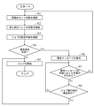
以下に、図5に示すフローチャートを参照し、搬送読取ジョブの実行前に制御部4が行う処理の流れを説明する。図5に示すフローは、搬送読取ジョブの実行指示を操作パネル6がユーザーから受け付けたときにスタートする。
ステップS1において、制御部4は、セットセンサーSSの出力に基づき、原稿Dのセット状態を確認する。言い換えると、制御部4は、搬送読取ジョブで搬送して読み取る原稿Dであるジョブ原稿Dが原稿トレイ200にセットされているか否かを確認する。
ステップS2において、制御部4は、カバーセンサーCSの出力に基づき、第2排出トレイ202の状態を確認する。言い換えると、制御部4は、第2排出トレイ202の開閉状態を確認する。さらに言い換えると、制御部4は、原稿搬送路20の排出口20Cが塞がれているか否かを確認する。
ステップS3において、制御部4は、操作パネル6がユーザーから受け付けた搬送読取ジョブの設定内容を確認する。制御部4は、経路設定および種類設定の各設定内容を確認する。
具体的には、制御部4は、第1搬送経路R1および第2搬送経路R2のうちいずれの搬送経路を使用する旨を操作パネル6が受け付けたかを確認する。言い換えると、制御部4は、第1モードおよび第2モードのうちいずれのモードで搬送読取ジョブを実行する旨を操作パネル6が受け付けたかを確認する。
たとえば、経路設定を受け付けるとき、操作パネル6は、第1モードおよび第2モードのいずれかを選択するモード選択操作をユーザーから受け付ける。制御部4は、モード選択操作で選択されたモードで搬送読取ジョブを実行する旨を受け付けたと判断する。モード選択操作が行われなかった場合、制御部4は、デフォルトモードである第1モードで搬送読取ジョブを実行する旨を受け付けたと判断する。
また、制御部4は、予め定められた複数の種類のいずれがジョブ原稿Dの種類として設定されたかを確認する。そして、制御部4は、複数の種類のうち設定された種類に対応付けられた厚さ(坪量)をジョブ原稿Dの厚さと認識する。
たとえば、種類設定を受け付けるとき、操作パネル6は、複数の種類のいずれかを選択する種類選択操作をユーザーから受け付ける。制御部4は、種類選択操作で選択された種類に対応付けられた厚さ(坪量)をジョブ原稿Dの厚さと認識する。種類選択操作が行われなかった場合、制御部4は、ジョブ原稿Dを普通紙(デフォルトの種類)と認識する。
なお、通常では、ジョブ原稿Dの種類が普通紙ではない特定種類(厚紙およびプラスチックカードなど)である場合、ユーザーは種類選択操作を行い、ジョブ原稿Dの種類(厚さ)を設定する。しかし、ユーザーによっては、ジョブ原稿Dの種類が特定種類であるにもかかわらず、種類設定を行わない場合がある。すなわち、実際にはジョブ原稿Dが厚紙およびプラスチックカードなどであるにもかかわらず、ジョブ原稿Dが普通紙であると制御部4が認識する場合がある。
ステップS4において、制御部4は、警告条件が満たされているか否かを判断する。まず、制御部4は、搬送読取ジョブの実行が可能か否かを判断する。搬送読取ジョブを実行できない場合、制御部4は、警告条件が満たされていると判断する。
具体的には、原稿トレイ200に原稿Dがセットされていない場合、搬送読取ジョブを実行できない。したがって、原稿トレイ200に原稿Dがセットされていないとき、制御部4は、警告条件が満たされていると判断する。
また、第2モードの搬送読取ジョブを実行する場合(第2搬送経路R2に沿ってジョブ原稿Dを搬送する場合)において、原稿搬送路20の排出口20Cが第2排出トレイ202によって塞がれていれば、ジョブ原稿Dを排出できない。すなわち、搬送読取ジョブを実行できない。したがって、第2搬送経路R2を使用する旨の設定がなされているにもかかわらず、第2排出トレイ202によって排出口20Cが塞がれていれば、制御部4は、警告条件が満たされていると判断する。
ここで、制御部4は、搬送読取ジョブをこのまま実行すると原稿Dの搬送に異常が発生する可能性があるか否かを判断する。そして、原稿Dの搬送に異常が発生する可能性がある場合、制御部4は、警告条件が満たされていると判断する。
具体的には、ジョブ原稿Dの種類が特定種類のとき、ジョブ原稿Dの搬送経路として第1搬送経路R1を使用すると、ジョブ原稿Dの破損、ジョブ原稿Dの読取不良およびジョブ原稿Dによるジャムなどが発生する可能性がある。このため、ジョブ原稿Dの種類が特定種類のとき、第1搬送経路R1を使用する旨の設定がなされていれば、制御部4は、警告条件が満たされていると判断する。
また、ジョブ原稿Dの種類が特定種類のとき、第2搬送経路R2を使用する旨の設定がなされていても、第2排出トレイ202によって排出口20Cが塞がれていれば、制御部4は、警告条件が満たされていると判断する。
すなわち、ジョブ原稿Dの種類が特定種類のとき、第2搬送経路R2を使用する旨の設定がなされており、かつ、第2排出トレイ202によって排出口20Cが塞がれていなければ、制御部4は、警告条件が満たされていないと判断する。
なお、第2搬送経路R2を使用する旨の設定がなされており、かつ、第2排出トレイ202によって排出口20Cが塞がれていなければ、制御部4は、ジョブ原稿Dの種類にかかわらず、警告条件が満たされていないと判断する。
また、第1搬送経路R1を使用する旨の設定がなされていても、ジョブ原稿Dの種類が特定種類でなければ、制御部4は、警告条件が満たされていないと判断する。
ステップS4において、警告条件が満たされていないと制御部4が判断した場合には、ステップS5に移行する。ステップS5に移行すると、制御部4は、搬送読取ジョブを開始する。
ステップS4において、警告条件が満たされていると制御部4が判断した場合には、ステップS6に移行する。ステップS6に移行すると、制御部4は、図6に示すような警告画面61を操作パネル6に表示させる。警告画面61には、警告メッセージMS1が配される。
図6に示す警告メッセージMS1は、ジョブ原稿Dの種類が特定種類であり、かつ、第1搬送経路R1を使用する旨の設定がなされている場合に表示される。この場合には、ジョブ原稿Dを痛める可能性がある旨のメッセージおよびジョブ原稿Dを正しく読み取れない可能性がある旨のメッセージなどが警告メッセージMS1に含められる。また、搬送読取ジョブの設定内容の確認を促すメッセージが警告メッセージMS1に含められる。
図示しないが、原稿トレイ200に原稿Dがセットされていない場合には、原稿Dのセット状態の確認を促すメッセージが警告メッセージMS1として表示される。第2搬送経路R2を使用する旨の設定がなされているにもかかわらず、第2排出トレイ202によって排出口20Cが塞がれている場合には、第2排出トレイ202(排出先)の状態の確認を促すメッセージが警告メッセージとMS1として表示される。
図5に戻り、警告メッセージMS1の表示後、ステップS7に移行する。ここで、警告メッセージMS1の確認後、必要であれば、ユーザーは何らかの対策をとる。たとえば、図6に示すような警告メッセージMS1が表示された場合、ユーザーはジョブ設定を見直し、使用する搬送経路を第1搬送経路R1から第2搬送経路R2に変更する。第2排出トレイ202の状態確認を促すメッセージが表示された場合、ユーザーは第2排出トレイ202を開ける。原稿Dのセット状態の確認を促すメッセージが表示された場合、ユーザーは原稿トレイ200に原稿Dをセットする。このような作業(警告メッセージMS1の内容に応じた作業)が行われたことを制御部4が検知した場合、ステップS1に移行する。
ユーザーによっては、警告メッセージMS1を確認しても、警告メッセージMS1の内容に応じた作業を行わず、搬送読取ジョブの実行指示を再度行う。この場合、ステップS7からステップS8に移行する。
たとえば、ステップS8において、制御部4は、搬送読取ジョブの実行指示を操作パネル6がユーザーから再度受け付けたか否かを判断する。搬送読取ジョブの実行指示を操作パネル6が受け付けたと制御部4が判断した場合には、ステップS5に移行し、搬送読取ジョブの実行指示を操作パネル6が受け付けていないと制御部4が判断した場合には、ステップS7に移行する。
ステップS8からステップS5に移行すると、ジョブ原稿Dの搬送に異常が発生し易い状態で、搬送読取ジョブが開始される。
なお、原稿トレイ200に原稿Dがセットされていない状態で、搬送読取ジョブの実行指示が行われた場合には、実行指示の受付後、原稿Dがセットされていない旨のエラーメッセージが表示される。第2搬送経路R2を使用する旨の設定がなされているにもかかわらず、第2排出トレイ202が閉じられ、その状態で、搬送読取ジョブの実行指示が行われた場合には、実行指示の受付後、第2排出トレイ202が閉じられている旨のエラーメッセージが表示される。
<ジャムの発生抑制>
搬送読取ジョブで読み取るジョブ原稿Dの種類が特定種類(厚紙およびプラスチックカードなど)であっても、第1搬送経路R1が使用され得る。すなわち、搬送読取ジョブが第1モードで実行され得る。この場合には、ジャムが発生し易くなる。ジョブ原稿Dが普通紙に比べて厚いほど、ジャムが発生し易い。
搬送読取ジョブで読み取るジョブ原稿Dの種類が特定種類(厚紙およびプラスチックカードなど)であっても、第1搬送経路R1が使用され得る。すなわち、搬送読取ジョブが第1モードで実行され得る。この場合には、ジャムが発生し易くなる。ジョブ原稿Dが普通紙に比べて厚いほど、ジャムが発生し易い。
そこで、制御部5は、搬送読取ジョブを開始して以降、ジャムが発生する可能性があるか否かを判断する。ジャムが発生する可能性がある場合、制御部4は、原稿搬送条件およびジャム検知条件などを変更することにより、ジャムの発生を抑制する。
以下に、図7に示すフローチャートを参照し、搬送読取ジョブの開始以降に制御部4が行う処理の流れを説明する。図7に示すフローは、搬送読取ジョブを開始したとき、すなわち、原稿トレイ200から原稿搬送路20にジョブ原稿Dを給紙したとき、スタートする。
ステップS11において、制御部4は、厚さセンサーTSの出力に基づき、ジョブ原稿Dの厚さを検知する。ここで、ユーザーにより設定されたジョブ原稿Dの種類に対応付けられた厚さ(坪量)と厚さセンサーTSの出力に基づき検知されるジョブ原稿Dの厚さ(以下、検知厚さと呼ぶ)とが一致するとは限らない。
ステップS12において、制御部4は、検知厚さに基づき、ジャムが発生する可能性があるか否かを判断する。ジャムが発生する可能性があるか否かの判断方法は特に限定されない。
たとえば、ジョブ原稿Dが普通紙よりも厚いほど、ジャムが発生し易い。また、第1搬送経路R1を使用する場合には、第2搬送経路R2を使用する場合よりも、ジャムが発生し易い。そこで、第1搬送経路R1を使用する旨の設定がなされた搬送読取ジョブにおいて、ジョブ原稿Dの厚さが所定厚さ以上であることを検知したとき、制御部4は、ジャムが発生する可能性があると判断する。
なお、ジョブ原稿Dが厚いほど、ジャムが発生し易い。したがって、ジョブ原稿Dの検知厚さが所定厚さ以上のとき、ジョブ原稿Dの搬送経路にかかわらず、ジャムが発生する可能性があると判断してもよい。
また、いずれかの搬送センサーFSの検知位置へのジョブ原稿Dの前端到達に遅れ(許容範囲内の遅れ)が生じている場合、ジャムが発生する可能性があると判断してもよい。
ステップS12において、ジャムが発生する可能性がないと制御部4が判断した場合には、ステップS13に移行する。ステップS13に移行すると、制御部4は、原稿搬送条件およびジャム検知条件などを変更するジャム抑制処理を行わず、搬送読取ジョブを継続する。
ステップS12において、ジャムが発生する可能性があると制御部4が判断した場合には、ステップS14に移行する。ステップS14に移行すると、制御部4は、搬送読取ジョブを中断する。すなわち、制御部4は、原稿搬送ユニット2によるジョブ原稿Dの搬送を停止する。
また、ステップS15において、制御部4は、図8に示すような確認画面62を操作パネル6に表示させる。確認画面62には、ジャムが発生する可能性がある旨のメッセージMS2が配される。また、確認画面62には、再開ボタンB1およびキャンセルボタンB2が配される。
制御部4は、再開ボタンB1に対する操作を検知すると、中断した搬送読取ジョブを再開する旨を操作パネル6がユーザーから受け付けたと判断する。一方で、制御部4は、キャンセルボタンB2に対する操作を検知すると、中断した搬送読取ジョブをキャンセルする旨を操作パネル6がユーザーから受け付けたと判断する。
図7に戻り、ステップS16において、制御部4は、搬送読取ジョブを再開する旨を操作パネル6が受け付けたか否かを判断する。搬送読取ジョブを再開する旨を受け付けたと制御部4が判断した場合には、ステップS17に移行する。
ステップS17に移行すると、制御部4は、ジャム抑制処理を行う。制御部4は、ジャム抑制処理として、第1処理および第2処理の少なくとも一方を行う。第1処理は、ジョブ原稿Dの搬送速度を変更する処理である。第2処理は、ジャム検知の設定を変更する処理である。
ここで、ジョブ原稿Dの搬送速度が遅いほど、ジョブ原稿Dによるジャムが発生し難くなる。そこで、制御部4は、第1処理として、ジョブ原稿Dの搬送速度を搬送読取ジョブの中断前よりも遅い速度に設定する処理を行う。
また、制御部4は、第2処理として、ジャム検知用のマージン時間を搬送読取ジョブの中断前よりも長い時間に設定する処理を行う。さらに、制御部4は、リトライ回数の上限回数を搬送読取ジョブの中断前よりも多い回数に設定する。第2処理が行われることにより、ジャムが検知され難くなる。
なお、第1処理が行われた場合、各搬送センサーFSの検知位置へのジョブ原稿Dの前端到達タイミングが遅くなる。このため、制御部4は、第1処理を行う場合、第2処理も行う。第1処理を行わず、第2処理だけを行ってもよい。ただし、ジャムの発生を抑制するには、ジョブ原稿Dの搬送速度を遅くするのが好ましい。
ステップS18において、制御部4は、中断した搬送読取ジョブを再開する。再開後の搬送読取ジョブでは、中断前よりも、ジョブ原稿Dの搬送速度が遅くなる。また、ジャム検知用のマージン時間が長くなり、リトライ回数の上限回数が多くなる。
ステップS16において、搬送読取ジョブを再開しない旨(搬送読取ジョブをキャンセルする旨)を受け付けたと制御部4が判断した場合には、ステップS19に移行する。ステップS19に移行すると、制御部4は、搬送読取ジョブをキャンセルする。
本実施形態の複合機100は、上記のように、搬送読取ジョブの設定を受け付ける操作パネル6と、ジョブ原稿Dの搬送をガイドする原稿搬送路20を有し、ジョブ原稿Dを原稿搬送路20に給紙して搬送する原稿搬送ユニット2と、操作パネル6が受け付けた搬送読取ジョブの設定内容に基づき、搬送読取ジョブを制御する制御部4と、を備える。ジョブ原稿Dの搬送経路には、一方側から他方側に向かって延び、途中で折り返して一方側に向かって延びる第1搬送経路R1と、途中で折り返さず直線的に延びる第2搬送経路R2とがある。
ここで、ジョブ原稿Dの種類が特定種類(厚紙およびプラスチックカードなど)である場合、第1搬送経路R1に沿ってジョブ原稿Dを搬送すると、ジョブ原稿Dが破損する可能性がある。また、ジョブ原稿Dの読取位置への到達タイミングが遅れ、ジョブ原稿Dの読み取りが正常に行われない可能性がある。
そこで、ジョブ原稿Dの種類が普通紙ではない特定種類のとき、第1搬送経路R1を使用する旨の設定がなされていれば、制御部4は、搬送読取ジョブの実行前に、操作パネル6に警告メッセージMS1を表示させる。警告メッセージM1が表示されると、ユーザーはジョブ設定を見直す。すなわち、ジョブ原稿Dの搬送経路が第1搬送経路R1から第2搬送経路R2に設定変更される。これにより、ジョブ原稿Dが破損するのを抑制できる。また、読取不良が発生するのを抑制できる。さらに、ジョブ原稿Dによるジャムも発生し難くなる。
また、本実施形態では、上記のように、ジョブ原稿Dの種類が特定種類のとき、第2搬送経路R2を使用する旨の設定がなされていても、第2排出トレイ202が閉じられていれば(原稿搬送路20の排出口20Cが塞がれていれば)、制御部4は、搬送読取ジョブの実行前に、操作パネル6に警告メッセージMS1を表示させる。これにより、搬送読取ジョブが実行できない(原稿搬送路20の排出口20Cが塞がれている)ことをユーザーに認識させることができる。警告メッセージMS1を確認したユーザーは、第2排出トレイ202を開けて、搬送読取ジョブの実行が可能な状態にする。
また、本実施形態では、上記のように、第2搬送経路R2を使用する旨の設定がなされており、かつ、第2排出トレイ202が開けられている場合、制御部4は、警告メッセージMS1を表示させない。これにより、警告メッセージMS1が不必要に表示されるのを抑制できる。
また、本実施形態では、上記のように、搬送読取ジョブの開始以降、制御部4は、ジョブ原稿Dによるジャムが発生する可能性があるか否かを判断する。そして、ジャムが発生する可能性があると判断したとき、制御部4は、搬送読取ジョブを中断し、搬送読取ジョブを再開するかキャンセルするかの受け付けを操作パネル6に行わせる。この構成では、ユーザーからすると、ジャムが発生する可能性があるか否かを認識でき、ジャムが発生する可能性がある場合には直ちに搬送読取ジョブをキャンセルできるので、利便性が良い。
この構成において、搬送読取ジョブを再開する旨を操作パネル6が受け付けたとき、制御部4は、ジャム抑制処理を行って、搬送読取ジョブを再開する。ユーザーからすると、搬送読取ジョブを再開するとき、別途設定を行わなくても、自動的にジャム抑制処理が行われるので、利便性が良い。
搬送読取ジョブを再開するとき、制御部4は、ジョブ原稿Dの搬送速度を搬送読取ジョブの中断前よりも遅い速度に設定する。また、制御部4は、ジャム検知用のマージン時間を搬送読取ジョブの中断前よりも長い時間に設定する。また、制御部4は、リトライ回数の上限回数を搬送読取ジョブの中断前よりも多い回数に設定する。これにより、容易に、ジャムを発生し難くすることができる。
また、本実施形態では、上記のように、制御部4は、ジョブ原稿Dの厚さに基づき、ジャムが発生する可能性があるか否かを判断する。具体的には、第1搬送経路R1を使用する旨の設定がなされた搬送読取ジョブにおいて、ジョブ原稿Dの厚さが所定厚さ以上であることを検知したとき、制御部4は、ジャムが発生する可能性があると判断する。この構成では、ジャムが発生するか否かの判断精度を高めることができる。
今回開示された実施形態は、すべての点で例示であって、制限的なものではないと考えられるべきである。本発明の範囲は、上記実施形態の説明ではなく特許請求の範囲によって示され、さらに、特許請求の範囲と均等の意味および範囲内でのすべての変更が含まれる。
Claims (9)
- 原稿を読み取って画像データを生成する読取ジョブの設定を受け付ける操作パネルと、
前記読取ジョブで読み取るジョブ原稿の搬送をガイドする原稿搬送路を有し、前記ジョブ原稿を前記原稿搬送路に給紙して搬送する原稿搬送ユニットと、
前記操作パネルが受け付けた前記読取ジョブの設定内容に基づき、前記読取ジョブを制御する制御部と、を備え、
前記ジョブ原稿の搬送経路には、一方側から他方側に向かって延び、途中で折り返して前記一方側に向かって延びる第1搬送経路と、途中で折り返さず直線的に延びる第2搬送経路とがあり、
前記ジョブ原稿の種類が普通紙ではない特定種類のとき、前記第1搬送経路を使用する旨の設定がなされていれば、前記制御部は、前記読取ジョブの実行前に、前記操作パネルに警告メッセージを表示させることを特徴とする画像読取装置。 - 前記原稿搬送ユニットに開閉可能に設けられ、閉じられることにより、前記第2搬送経路の排出口を塞ぐカバーを備え、
前記ジョブ原稿の種類が前記特定種類のとき、前記第2搬送経路を使用する旨の設定がなされていても、前記カバーが閉じられていれば、前記制御部は、前記読取ジョブの実行前に、前記操作パネルに前記警告メッセージを表示させることを特徴とする請求項1に記載の画像読取装置。 - 前記第2搬送経路を使用する旨の設定がなされており、かつ、前記カバーが開けられている場合、前記制御部は、前記警告メッセージを表示させないことを特徴とする請求項2に記載の画像読取装置。
- 前記読取ジョブの開始以降、前記制御部は、前記ジョブ原稿によるジャムが発生する可能性があるか否かを判断し、
前記ジャムが発生する可能性があると判断したとき、前記制御部は、前記読取ジョブを中断し、前記読取ジョブを再開するかキャンセルするかの受け付けを前記操作パネルに行わせることを特徴とする請求項1に記載の画像読取装置。 - 前記読取ジョブを再開する旨を前記操作パネルが受け付けたとき、前記制御部は、前記ジョブ原稿の搬送速度を前記読取ジョブの中断前よりも遅い速度に設定して前記読取ジョブを再開することを特徴とする請求項4に記載の画像読取装置。
- 前記原稿搬送路の第1位置から第2位置に向かって搬送される前記ジョブ原稿の前端が前記第2位置への理論上の到達予定時点からマージン時間が経過した時点になっても到達しなかったとき、前記制御部は、前記ジャムが発生したと判断し、
前記読取ジョブを再開する旨を前記操作パネルが受け付けたとき、前記制御部は、前記マージン時間を前記読取ジョブの中断前よりも長い時間に設定して前記読取ジョブを再開することを特徴とする請求項4に記載の画像読取装置。 - 回転することにより、前記原稿搬送路の所定位置に向けて前記ジョブ原稿を搬送するローラー部材を備え、
前記ローラー部材による前記ジョブ原稿の搬送開始から所定時間が経過しても、前記ジョブ原稿の前端が前記所定位置に到達しなかったとき、前記制御部は、前記ローラー部材の回転を停止させてから、前記ローラー部材による前記ジョブ原稿の搬送をリトライし、
前記ローラー部材による前記ジョブ原稿の搬送のリトライ回数が上限回数に達しても、前記ジョブ原稿の前端が前記所定位置に到達しなかったとき、前記制御部は、前記ジャムが発生したと判断し、
前記読取ジョブを再開する旨を前記操作パネルが受け付けたとき、前記制御部は、前記上限回数を前記読取ジョブの中断前よりも多い回数に設定して前記読取ジョブを再開することを特徴とする請求項4に記載の画像読取装置。 - 前記原稿搬送路に給紙された前記ジョブ原稿の厚さを検知する厚さセンサーを備え、
前記制御部は、前記ジョブ原稿の厚さに基づき、前記ジャムが発生する可能性があるか否かを判断することを特徴とする請求項4に記載の画像読取装置。 - 前記第1搬送経路を使用する旨の設定がなされた前記読取ジョブにおいて、前記ジョブ原稿の厚さが所定厚さ以上であることを検知したとき、前記制御部は、前記ジャムが発生する可能性があると判断することを特徴とする請求項8に記載の画像読取装置。
Priority Applications (2)
| Application Number | Priority Date | Filing Date | Title |
|---|---|---|---|
| US18/006,114 US11856166B2 (en) | 2020-07-21 | 2021-07-19 | Image reading apparatus which prevents damage to documents to be read which are thicker than regular paper |
| JP2022537990A JP7472986B2 (ja) | 2020-07-21 | 2021-07-19 | 画像読取装置 |
Applications Claiming Priority (2)
| Application Number | Priority Date | Filing Date | Title |
|---|---|---|---|
| JP2020-124552 | 2020-07-21 | ||
| JP2020124552 | 2020-07-21 |
Publications (1)
| Publication Number | Publication Date |
|---|---|
| WO2022019250A1 true WO2022019250A1 (ja) | 2022-01-27 |
Family
ID=79729568
Family Applications (1)
| Application Number | Title | Priority Date | Filing Date |
|---|---|---|---|
| PCT/JP2021/026912 Ceased WO2022019250A1 (ja) | 2020-07-21 | 2021-07-19 | 画像読取装置 |
Country Status (3)
| Country | Link |
|---|---|
| US (1) | US11856166B2 (ja) |
| JP (1) | JP7472986B2 (ja) |
| WO (1) | WO2022019250A1 (ja) |
Cited By (1)
| Publication number | Priority date | Publication date | Assignee | Title |
|---|---|---|---|---|
| JP2023120786A (ja) * | 2022-02-18 | 2023-08-30 | セイコーエプソン株式会社 | 読取装置、読取装置の制御方法、プログラム、及び、画像読取システム |
Families Citing this family (1)
| Publication number | Priority date | Publication date | Assignee | Title |
|---|---|---|---|---|
| JP2024000882A (ja) * | 2022-06-21 | 2024-01-09 | 京セラドキュメントソリューションズ株式会社 | 画像読取装置、及び画像形成装置 |
Citations (8)
| Publication number | Priority date | Publication date | Assignee | Title |
|---|---|---|---|---|
| JP2003069792A (ja) * | 2001-08-28 | 2003-03-07 | Oki Data Corp | 用紙厚検出装置及びそれを用いた画像読取り装置 |
| JP2008005278A (ja) * | 2006-06-23 | 2008-01-10 | Murata Mach Ltd | 画像読取装置 |
| JP2008127116A (ja) * | 2006-11-16 | 2008-06-05 | Ricoh Co Ltd | 画像形成装置 |
| JP2012034186A (ja) * | 2010-07-30 | 2012-02-16 | Sharp Corp | 画像読取り装置、及びそれを備える画像形成装置 |
| JP2017218273A (ja) * | 2016-06-06 | 2017-12-14 | 株式会社リコー | 自動原稿搬送装置、画像読取装置および画像形成装置 |
| JP2019033413A (ja) * | 2017-08-09 | 2019-02-28 | 株式会社リコー | 読取装置及び画像形成装置 |
| JP2020015565A (ja) * | 2018-07-23 | 2020-01-30 | 京セラドキュメントソリューションズ株式会社 | 給紙装置および画像形成装置 |
| JP2020108036A (ja) * | 2018-12-27 | 2020-07-09 | キヤノン株式会社 | 画像読取装置、画像読取装置の制御方法、及びプログラム |
Family Cites Families (2)
| Publication number | Priority date | Publication date | Assignee | Title |
|---|---|---|---|---|
| JP2013026874A (ja) | 2011-07-22 | 2013-02-04 | Canon Electronics Inc | 画像読取装置、画像読取装置の制御方法、及びプログラム |
| JP7224929B2 (ja) * | 2019-01-21 | 2023-02-20 | キヤノン株式会社 | 画像読取装置、画像読取装置の制御方法、及びプログラム |
-
2021
- 2021-07-19 JP JP2022537990A patent/JP7472986B2/ja active Active
- 2021-07-19 WO PCT/JP2021/026912 patent/WO2022019250A1/ja not_active Ceased
- 2021-07-19 US US18/006,114 patent/US11856166B2/en active Active
Patent Citations (8)
| Publication number | Priority date | Publication date | Assignee | Title |
|---|---|---|---|---|
| JP2003069792A (ja) * | 2001-08-28 | 2003-03-07 | Oki Data Corp | 用紙厚検出装置及びそれを用いた画像読取り装置 |
| JP2008005278A (ja) * | 2006-06-23 | 2008-01-10 | Murata Mach Ltd | 画像読取装置 |
| JP2008127116A (ja) * | 2006-11-16 | 2008-06-05 | Ricoh Co Ltd | 画像形成装置 |
| JP2012034186A (ja) * | 2010-07-30 | 2012-02-16 | Sharp Corp | 画像読取り装置、及びそれを備える画像形成装置 |
| JP2017218273A (ja) * | 2016-06-06 | 2017-12-14 | 株式会社リコー | 自動原稿搬送装置、画像読取装置および画像形成装置 |
| JP2019033413A (ja) * | 2017-08-09 | 2019-02-28 | 株式会社リコー | 読取装置及び画像形成装置 |
| JP2020015565A (ja) * | 2018-07-23 | 2020-01-30 | 京セラドキュメントソリューションズ株式会社 | 給紙装置および画像形成装置 |
| JP2020108036A (ja) * | 2018-12-27 | 2020-07-09 | キヤノン株式会社 | 画像読取装置、画像読取装置の制御方法、及びプログラム |
Cited By (2)
| Publication number | Priority date | Publication date | Assignee | Title |
|---|---|---|---|---|
| JP2023120786A (ja) * | 2022-02-18 | 2023-08-30 | セイコーエプソン株式会社 | 読取装置、読取装置の制御方法、プログラム、及び、画像読取システム |
| JP7865024B2 (ja) | 2022-02-18 | 2026-05-26 | セイコーエプソン株式会社 | 読取装置、読取装置の制御方法、プログラム、及び、画像読取システム |
Also Published As
| Publication number | Publication date |
|---|---|
| JPWO2022019250A1 (ja) | 2022-01-27 |
| JP7472986B2 (ja) | 2024-04-23 |
| US20230283727A1 (en) | 2023-09-07 |
| US11856166B2 (en) | 2023-12-26 |
Similar Documents
| Publication | Publication Date | Title |
|---|---|---|
| CN101891073B (zh) | 图像形成装置 | |
| JP5815493B2 (ja) | シート搬送装置、原稿搬送装置および画像形成装置 | |
| US12069208B2 (en) | Image forming apparatus, type information processing method of recording medium, and program for identifying a cause of failure | |
| JP2013082539A (ja) | 給紙装置、原稿搬送装置、画像形成装置 | |
| JP7472986B2 (ja) | 画像読取装置 | |
| CN105467791B (zh) | 图像形成装置 | |
| US11825049B2 (en) | Image-reading device | |
| US9146519B2 (en) | Sheet conveying device and image forming apparatus having same | |
| JP2022046977A (ja) | 画像読取装置および画像形成装置 | |
| JP6642514B2 (ja) | 原稿搬送装置、画像読取装置、原稿搬送方法 | |
| JP4898553B2 (ja) | 重送検知装置、画像形成装置 | |
| JP7452218B2 (ja) | 画像読取装置および画像形成装置 | |
| JP2020015565A (ja) | 給紙装置および画像形成装置 | |
| JP2007223688A (ja) | シート搬送装置及び画像形成装置 | |
| JP6589687B2 (ja) | 自動原稿搬送装置、およびそれを備えた画像読取システムと画像形成装置 | |
| CN112299068A (zh) | 输送装置 | |
| JP2017128421A (ja) | 自動原稿搬送装置、およびそれを備えた画像読取システムと画像形成装置 | |
| JP2016159997A (ja) | 画像形成装置 | |
| JP2007137618A (ja) | シート搬送装置 | |
| US10791233B2 (en) | Image forming apparatus capable of performing a print job to print an image on a sheet being conveyed | |
| JP2019134382A (ja) | シート搬送装置、シート搬送方法、及びプログラム | |
| JP6652749B2 (ja) | 原稿搬送装置及び該原稿搬送装置を備えた画像形成装置 | |
| JP4876035B2 (ja) | シート材搬送装置、原稿搬送装置、給紙装置および画像形成装置 | |
| JP2018150148A (ja) | 原稿搬送装置、及び、画像形成装置 | |
| JP6669126B2 (ja) | 原稿搬送装置、画像読取装置、原稿搬送方法 |
Legal Events
| Date | Code | Title | Description |
|---|---|---|---|
| 121 | Ep: the epo has been informed by wipo that ep was designated in this application |
Ref document number: 21846773 Country of ref document: EP Kind code of ref document: A1 |
|
| ENP | Entry into the national phase |
Ref document number: 2022537990 Country of ref document: JP Kind code of ref document: A |
|
| NENP | Non-entry into the national phase |
Ref country code: DE |
|
| 122 | Ep: pct application non-entry in european phase |
Ref document number: 21846773 Country of ref document: EP Kind code of ref document: A1 |