WO2021240953A1 - 蝶番の取付け構造 - Google Patents
蝶番の取付け構造 Download PDFInfo
- Publication number
- WO2021240953A1 WO2021240953A1 PCT/JP2021/010016 JP2021010016W WO2021240953A1 WO 2021240953 A1 WO2021240953 A1 WO 2021240953A1 JP 2021010016 W JP2021010016 W JP 2021010016W WO 2021240953 A1 WO2021240953 A1 WO 2021240953A1
- Authority
- WO
- WIPO (PCT)
- Prior art keywords
- piece
- door
- hinge
- mounting structure
- shaft
- Prior art date
- Legal status (The legal status is an assumption and is not a legal conclusion. Google has not performed a legal analysis and makes no representation as to the accuracy of the status listed.)
- Ceased
Links
Images








Classifications
-
- E—FIXED CONSTRUCTIONS
- E05—LOCKS; KEYS; WINDOW OR DOOR FITTINGS; SAFES
- E05D—HINGES OR SUSPENSION DEVICES FOR DOORS, WINDOWS OR WINGS
- E05D3/00—Hinges with pins
- E05D3/02—Hinges with pins with one pin
-
- E—FIXED CONSTRUCTIONS
- E06—DOORS, WINDOWS, SHUTTERS, OR ROLLER BLINDS IN GENERAL; LADDERS
- E06B—FIXED OR MOVABLE CLOSURES FOR OPENINGS IN BUILDINGS, VEHICLES, FENCES OR LIKE ENCLOSURES IN GENERAL, e.g. DOORS, WINDOWS, BLINDS, GATES
- E06B3/00—Window sashes, door leaves, or like elements for closing wall or like openings; Layout of fixed or moving closures, e.g. windows in wall or like openings; Features of rigidly-mounted outer frames relating to the mounting of wing frames
- E06B3/32—Arrangements of wings characterised by the manner of movement; Arrangements of movable wings in openings; Features of wings or frames relating solely to the manner of movement of the wing
- E06B3/34—Arrangements of wings characterised by the manner of movement; Arrangements of movable wings in openings; Features of wings or frames relating solely to the manner of movement of the wing with only one kind of movement
- E06B3/36—Arrangements of wings characterised by the manner of movement; Arrangements of movable wings in openings; Features of wings or frames relating solely to the manner of movement of the wing with only one kind of movement with a single vertical axis of rotation at one side of the opening, or swinging through the opening
-
- E—FIXED CONSTRUCTIONS
- E05—LOCKS; KEYS; WINDOW OR DOOR FITTINGS; SAFES
- E05D—HINGES OR SUSPENSION DEVICES FOR DOORS, WINDOWS OR WINGS
- E05D11/00—Additional features or accessories of hinges
- E05D11/0054—Covers, e.g. for protection
-
- E—FIXED CONSTRUCTIONS
- E05—LOCKS; KEYS; WINDOW OR DOOR FITTINGS; SAFES
- E05D—HINGES OR SUSPENSION DEVICES FOR DOORS, WINDOWS OR WINGS
- E05D5/00—Construction of single parts, e.g. the parts for attachment
- E05D5/02—Parts for attachment, e.g. flaps
- E05D5/06—Bent flaps
-
- E—FIXED CONSTRUCTIONS
- E05—LOCKS; KEYS; WINDOW OR DOOR FITTINGS; SAFES
- E05D—HINGES OR SUSPENSION DEVICES FOR DOORS, WINDOWS OR WINGS
- E05D7/00—Hinges or pivots of special construction
- E05D7/04—Hinges adjustable relative to the wing or the frame
- E05D7/0415—Hinges adjustable relative to the wing or the frame with adjusting drive means
-
- E—FIXED CONSTRUCTIONS
- E05—LOCKS; KEYS; WINDOW OR DOOR FITTINGS; SAFES
- E05D—HINGES OR SUSPENSION DEVICES FOR DOORS, WINDOWS OR WINGS
- E05D3/00—Hinges with pins
- E05D3/02—Hinges with pins with one pin
- E05D2003/025—Hinges with pins with one pin having three knuckles
- E05D2003/027—Hinges with pins with one pin having three knuckles the end knuckles being mutually connected
-
- E—FIXED CONSTRUCTIONS
- E05—LOCKS; KEYS; WINDOW OR DOOR FITTINGS; SAFES
- E05D—HINGES OR SUSPENSION DEVICES FOR DOORS, WINDOWS OR WINGS
- E05D7/00—Hinges or pivots of special construction
- E05D7/04—Hinges adjustable relative to the wing or the frame
- E05D2007/0469—Hinges adjustable relative to the wing or the frame in an axial direction
-
- E—FIXED CONSTRUCTIONS
- E05—LOCKS; KEYS; WINDOW OR DOOR FITTINGS; SAFES
- E05D—HINGES OR SUSPENSION DEVICES FOR DOORS, WINDOWS OR WINGS
- E05D7/00—Hinges or pivots of special construction
- E05D7/04—Hinges adjustable relative to the wing or the frame
- E05D2007/0484—Hinges adjustable relative to the wing or the frame in a radial direction
-
- E—FIXED CONSTRUCTIONS
- E05—LOCKS; KEYS; WINDOW OR DOOR FITTINGS; SAFES
- E05D—HINGES OR SUSPENSION DEVICES FOR DOORS, WINDOWS OR WINGS
- E05D7/00—Hinges or pivots of special construction
- E05D7/04—Hinges adjustable relative to the wing or the frame
- E05D2007/0492—Hinges adjustable relative to the wing or the frame in three directions
-
- E—FIXED CONSTRUCTIONS
- E05—LOCKS; KEYS; WINDOW OR DOOR FITTINGS; SAFES
- E05D—HINGES OR SUSPENSION DEVICES FOR DOORS, WINDOWS OR WINGS
- E05D11/00—Additional features or accessories of hinges
- E05D11/0054—Covers, e.g. for protection
- E05D2011/0063—Covers, e.g. for protection for screw-heads or bolt-heads
-
- E—FIXED CONSTRUCTIONS
- E05—LOCKS; KEYS; WINDOW OR DOOR FITTINGS; SAFES
- E05D—HINGES OR SUSPENSION DEVICES FOR DOORS, WINDOWS OR WINGS
- E05D5/00—Construction of single parts, e.g. the parts for attachment
- E05D5/02—Parts for attachment, e.g. flaps
- E05D5/0215—Parts for attachment, e.g. flaps for attachment to profile members or the like
-
- E—FIXED CONSTRUCTIONS
- E05—LOCKS; KEYS; WINDOW OR DOOR FITTINGS; SAFES
- E05D—HINGES OR SUSPENSION DEVICES FOR DOORS, WINDOWS OR WINGS
- E05D7/00—Hinges or pivots of special construction
- E05D7/04—Hinges adjustable relative to the wing or the frame
- E05D7/0415—Hinges adjustable relative to the wing or the frame with adjusting drive means
- E05D7/0423—Screw-and-nut mechanisms
-
- E—FIXED CONSTRUCTIONS
- E05—LOCKS; KEYS; WINDOW OR DOOR FITTINGS; SAFES
- E05Y—INDEXING SCHEME ASSOCIATED WITH SUBCLASSES E05D AND E05F, RELATING TO CONSTRUCTION ELEMENTS, ELECTRIC CONTROL, POWER SUPPLY, POWER SIGNAL OR TRANSMISSION, USER INTERFACES, MOUNTING OR COUPLING, DETAILS, ACCESSORIES, AUXILIARY OPERATIONS NOT OTHERWISE PROVIDED FOR, APPLICATION THEREOF
- E05Y2201/00—Constructional elements; Accessories therefor
- E05Y2201/10—Covers; Housings
- E05Y2201/11—Covers
-
- E—FIXED CONSTRUCTIONS
- E05—LOCKS; KEYS; WINDOW OR DOOR FITTINGS; SAFES
- E05Y—INDEXING SCHEME ASSOCIATED WITH SUBCLASSES E05D AND E05F, RELATING TO CONSTRUCTION ELEMENTS, ELECTRIC CONTROL, POWER SUPPLY, POWER SIGNAL OR TRANSMISSION, USER INTERFACES, MOUNTING OR COUPLING, DETAILS, ACCESSORIES, AUXILIARY OPERATIONS NOT OTHERWISE PROVIDED FOR, APPLICATION THEREOF
- E05Y2900/00—Application of doors, windows, wings or fittings thereof
- E05Y2900/10—Application of doors, windows, wings or fittings thereof for buildings or parts thereof
- E05Y2900/13—Type of wing
- E05Y2900/132—Doors
-
- E—FIXED CONSTRUCTIONS
- E06—DOORS, WINDOWS, SHUTTERS, OR ROLLER BLINDS IN GENERAL; LADDERS
- E06B—FIXED OR MOVABLE CLOSURES FOR OPENINGS IN BUILDINGS, VEHICLES, FENCES OR LIKE ENCLOSURES IN GENERAL, e.g. DOORS, WINDOWS, BLINDS, GATES
- E06B1/00—Border constructions of openings in walls, floors, or ceilings; Frames to be rigidly mounted in such openings
- E06B1/04—Frames for doors, windows, or the like to be fixed in openings
- E06B1/52—Frames specially adapted for doors
Definitions
- the present invention relates to a hinge mounting structure mainly used for building structures.
- Patent Document 1 discloses a hinge mounting structure in which the hinge shaft is retracted and the center of the hinge shaft is arranged at the same position as the front line of the side frame.
- the present invention has been made in view of the above problems, and an object of the present invention is to provide a hinge mounting structure capable of improving the appearance.
- the first piece of a hinge having a first piece and a second piece connected so as to be relatively rotatable via a shaft is attached to a side frame, and the second piece is attached.
- the hinge mounting structure in which a piece is attached to a door the hinge is provided with a convex portion protruding forward from the wall surface on the side frame, and the center of the shaft is arranged behind the front line of the convex portion of the side frame. It is a mounting structure.
- the center of the shaft is installed behind the front line of the convex portion of the side frame, the appearance can be improved.
- FIG. 2 (a) is a closed position of the second piece
- FIG. 2 (b) is a 90-degree open position of the second piece
- FIG. 2 (c) is a 180-degree open position of the second piece. Shows).
- FIG. 9 (a) shows a door closing position
- FIG. 9 (b) shows a door opening position by 90 degrees
- FIG. 9 (c) shows a door opening position by 180 degrees.
- FIG. 9 (a) shows a door closing position
- FIG. 9 (b) shows a door opening position by 90 degrees
- FIG. 9 (c) shows a door opening position by 180 degrees.
- FIG. 9 (a) shows a door closing position
- FIG. 9 (b) shows a door opening position by 90 degrees
- FIG. 9 (c) shows a door opening position by 180 degrees.
- FIG. 9 (c) shows a door opening position by 180 degrees.
- 2A is a horizontal cross-sectional view of the hinge mounting structure of the second embodiment of the present invention (FIG.
- FIG. 12 (a) is a door closed position
- FIG. 12 (b) is a door 90 degree open position
- FIG. 12 (c) is. Indicates the 180 degree opening position of the door).
- FIG. 19 (a) shows a door closing position
- FIG. 19 (b) shows a door opening position by 90 degrees
- FIG. 19 (c) shows a door opening position by 180 degrees.
- FIG. 20 (a) shows the door closing position
- FIG. 20 (b) shows the door opening position by 90 degrees
- FIG. 20 (c) shows the door opening position by 180 degrees.
- FIG. 20 (a) shows the door closing position
- FIG. 20 (b) shows the door opening position by 90 degrees
- FIG. 20 (c) shows the door opening position by 180 degrees.
- FIG. 20 (a) shows the door closing position
- FIG. 20 (c) shows the door opening position by 180 degrees.
- FIG. 22 (a) is a perspective view of a hinge used in the hinge mounting structure of the fifth embodiment of the present invention (FIG. 22 (a) shows a state in which a cover is attached, and FIG. 22 (b) shows a state in which the cover is removed). .. It is an exploded perspective view of the said hinge.
- FIG. 24A is a perspective view of the eccentric cam as the vertical adjustment portion of the hinge
- FIG. 24B is a perspective view of the eccentric cam as the front-rear adjustment portion of the hinge.
- FIG. 25 (b) shows the lower end position of a mounting plate).
- FIG. 26 (a) shows the left end position of an intermediate plate
- FIG. 26 (b) shows the right end position of an intermediate plate. show
- FIG. 27 (a) shows the position of the rear end of an intermediate plate
- FIG. 27 (c) is a sectional view taken along line AA of FIG. 27 (a)
- FIG. 27 (d) is a sectional view taken along line BB of FIG. 27 (b).
- FIG. 1 is an exploded perspective view of a hinge used in the hinge mounting structure of the first embodiment of the present invention.
- the hinge 1 includes a shaft 2 and a first piece 3 and a second piece 4 that are rotatably connected to each other via the shaft 2.
- the first piece 3 includes a substantially rectangular main body portion 11 and tubular portions 12a and 12b. Two tubular portions 12a and 12b are integrally formed at the widthwise end of the main body portion 11.
- the second piece 4 includes a substantially rectangular main body portion 13 and a tubular portion 14.
- One tubular portion 14 is integrally formed at the end portion of the main body portion 13 in the width direction.
- the shaft 2 is inserted into the tubular portions 12a and 12b of the first piece 3 and the tubular portions 14 of the second piece 4.
- the tubular portion 14 of the second piece 4 is arranged between the tubular portions 12a and 12b of the first piece 3.
- the height of the main body 13 of the second piece 4 is substantially the same as the height of the main body 11 of the first piece 3.
- the shapes of the first piece 3 and the second piece 4 are examples, and the shape is not limited thereto.
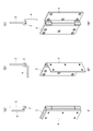
- FIG. 2 is an operation diagram of hinge 1.
- the upper part of FIG. 2 shows a plan view of the hinge 1, and the lower part of FIG. 2 shows a perspective view of the hinge 1.
- FIG. 2A shows the closing position (0 degree opening position) of the second piece 4
- FIG. 2B shows the 90 degree opening position of the second piece 4
- FIG. 2C shows the 180 degree opening position of the second piece 4. Indicates the position.
- the second piece 4 can rotate from 0 degrees to approximately 180 degrees with respect to the first piece 3.
- the first piece 3 is substantially I-shaped
- the second piece 4 is substantially L-shaped.
- the main body 11 of the first piece 3 and the main body 13 of the second piece 4 are parallel to each other.
- the first piece 3 and the second piece 4 are orthogonal to each other.
- the first piece 3 and the second piece 4 are in an expanded state and are parallel to each other.
- the planar shapes of the first piece 3 and the second piece 4 are not limited to a substantially I-shape and a substantially L-shape.
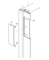
- FIG. 3 is a perspective view of the hinge mounting structure (when the door 5 is in the open position) of the present embodiment.
- FIG. 4 is a horizontal cross-sectional view of the hinge mounting structure (when the door 5 is in the closed position) of the present embodiment.
- the hinge mounting structure will be described using each direction when the door 5 in the closed position is viewed from the open side, that is, the front-back, up-down, and left-right directions of FIGS. 3 and 4. explain.
- the first piece 3 of the hinge 1 is attached to one of the side frames 6 and 6 (see FIG. 4) arranged on the left and right sides of the door 5.
- the second piece 4 of the hinge 1 is attached to the end surface (kiguchi) of the door 5.
- the side frame 6 is attached to the wall 7.
- the side frame 6 is provided with a convex portion 8 projecting forward from the wall surface 7a.
- the convex portion 8 extends in the vertical direction above the height of the door 5.
- a cut portion 6a having a depth width Y larger than the thickness of the door 5 and an appropriate depth is formed on the inner side surface of the side frame 6.
- a rectangular recess 6b is formed in the notch 6a of the side frame 6.
- the first piece 3 is attached to the recess 6b.
- Reference numeral 15 is a screw hole into which the screw 17 (see FIG. 3) is screwed.
- a part 6b1 (front end portion) of the concave portion 6b penetrates the convex portion 8 of the side frame 6 in the left-right direction. This facilitates the placement of the hinge 1 axis 2 (see FIG. 3) within the convex portion 8.
- the recess 6b is covered with the cover 16. As a result, the screw 17 can be hidden to improve the appearance.
- the cover 16 is detachably attached to the side frame 6 by the hook 16a.
- the frame of the present embodiment is made of metal such as aluminum and sheet metal, but the material of the side frame 6 is not particularly limited. Further, the concave portion 6b may be formed on the front surface of the convex portion 8.
- a recess 5a extending in the vertical direction is formed on the end surface of the door 5.
- the second piece 4 is attached to the recess 5a.
- the recess 5a is covered with the cover 18.
- the screw 19 see FIG. 7 can be hidden to improve the appearance.
- the cover 18 is detachably attached to the door 5 by the hook 18a.
- FIG. 9 shows a horizontal sectional view of the hinge mounting structure of the present embodiment.
- 9 (a) shows the closed position of the door 5
- FIG. 9 (b) shows the 90-degree open position of the door 5
- FIG. 9 (c) shows the 180-degree open position of the door 5.
- the center C of the axis 2 of the hinge 1 is arranged behind the front line X of the convex portion 8.
- the hinge 1 can be made inconspicuous, and the appearance can be improved.
- the gap between the door 5 and the convex portion 8 can be reduced, for example, the user sandwiches a finger between them. Can be prevented.
- the door 5 in the closed position exists behind the front line X of the convex portion 8.
- the door 5 in the closed position shown in FIG. 9A rotates to the open position, the door 5 gets over the convex portion 8.
- FIG. 9C at least a part of the door 5 is located behind the front line X of the convex portion 8 at the opening position of the door 5.
- the opening angle of the door 5 at the opening position is not limited to 180 degrees, and may be any angle such as 190 degrees or 170 degrees.
- the center C of the shaft 2 is arranged between the inner side surface 8b and the outer side surface 8c of the convex portion 8.
- the opening dimension L can be increased at the 90-degree opening position of the door 5.
- FIG. 10 and 11 are perspective views of the hinge mounting structure (when the door 5 is in the closed position) of the present embodiment.
- FIG. 10 is a perspective view seen from the door 5 side
- FIG. 11 is a perspective view seen from the wall side.
- the front surfaces 12a1, 12b1 of the tubular portions 12a and 12b of the first piece 3 and the front surface 14a of the tubular portion 14 of the second piece 4 are the front surfaces 8a of the convex portion 8. They are substantially on the same plane.
- the outer surfaces 12a2 and 12b2 of the tubular portions 12a and 12b of the first piece 3 and the outer surface 14b of the tubular portion 14 of the second piece 4 are outside the convex portion 8. It exists substantially on the same surface as the side surface 8c. This can improve the appearance.
- the front surface 8a and the outer surface 8c of the convex portion 8 are at right angles.
- the front surfaces 12a1, 12b1 and the outer surfaces 12a2, 12b2 of the tubular portions 12a, 12b of the first piece 3 are at right angles.
- the front surface 14a and the outer surface 14b of the tubular portion 14 of the second piece 4 are at right angles.
- the front surface 8a and the outer surface 8c of the convex portion 8, the front surfaces 12a1, 12b1 and the outer surfaces 12a2, 12b2 of the tubular portions 12a and 12b of the first piece 3, and the front surface 14a and the outer surface 14b of the tubular portion 14 of the second piece 4 Is formed on a flat surface, but may be formed on a curved surface having a horizontal cross section such as an arc shape. (Second embodiment)
- FIG. 12 shows a horizontal cross-sectional view of the hinge mounting structure of the second embodiment of the present invention.
- 12 (a) shows the closed position of the door 5
- FIG. 12 (b) shows the 90 degree opening position of the door 5
- FIG. 12 (c) shows the 180 degree opening position of the door 5. Since the structure of the wall 7, the side frame 6, and the hinge 1 is the same as the hinge mounting structure of the first embodiment, the same reference numerals are given and the description thereof will be omitted.
- the center C of the shaft 2 of the hinge 1 is the convex portion 8 as in the hinge mounting structure of the first embodiment. It is placed behind the front line X. Further, as shown in FIG. 12B, the center C of the shaft 2 is arranged between the inner side surface 8b and the outer side surface 8c of the convex portion 8.
- the hinge mounting structure of the first embodiment at least a part of the door 5 is located behind the front line X at the opening position of the door 5.
- the door 5 is located in front of the front line X at the opening position of the door 5, but the hinge is present. At least a part of the second piece 4 of 1 is behind the front line X.
- the door 5 in the closed position is located behind the front line X of the convex portion 8.
- the door 5 in the closed position shown in FIG. 12A rotates to the open position, the door 5 gets over the convex portion 8.
- a part of the second piece 4 of the hinge 1 exists behind the front line X of the convex portion 8 at the opening position of the door 5.
- the opening angle of the door 5 at the opening position is not limited to 180 degrees, and may be any angle such as 190 degrees or 170 degrees. (Third embodiment)
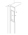
- the side frame 6 is made of metal, whereas in the third embodiment, the side frame 6 is made of wood. Since the configuration of the hinge 1 is substantially the same as that of the hinge 1 of the first embodiment, the same reference numerals are given and the description thereof will be omitted.
- the first piece 3 of the hinge 1 is attached to the side frame 6 by a screw.
- the second piece 4 of the hinge 1 is attached to the end face of the door 5 by a screw.
- the side frame 6 is provided with a convex portion 8 projecting forward from the wall surface 7a.
- a recess 6b is formed on the inner surface of the side frame 6.
- the first piece 3 is attached to the recess 6b.
- Reference numeral 27 is a screw hole into which a screw is screwed.
- FIG. 15 is a perspective view of the hinge mounting structure (when the door 5 is in the closed position) of the present embodiment. Similar to the first embodiment, the center C of the axis 2 of the hinge 1 (see FIG. 9A) is arranged behind the front line X of the convex portion 8. Further, the center C of the shaft 2 of the hinge 1 is arranged between the inner side surface 8b and the outer side surface 8c of the convex portion 8. At the closed position of the door 5, the front surfaces 12a1, 12b1 of the tubular portions 12a and 12b of the first piece 3 and the front surface 14a of the tubular portion 14 of the second piece 4 are substantially in the same plane as the front surface 8a of the convex portion 8.
- the outer surfaces 12a2 and 12b2 of the tubular portions 12a and 12b of the first piece 3 and the outer surface 14b of the tubular portion 14 of the second piece 4 are substantially in the same plane as the outer surface 8c of the convex portion 8. According to the hinge mounting structure of the third embodiment, the same effect as that of the hinge mounting structure of the first embodiment is obtained. (Fourth Embodiment)
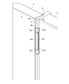
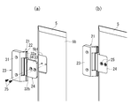
- FIG. 16 shows a hinge mounting structure according to a fourth embodiment of the present invention.
- 21 is a hinge
- 23 is the first piece of the hinge
- 24 is the second piece of the hinge
- 6 is the side frame
- 20 is the upper frame
- 7a is the wall surface
- 5 is the door.
- the horizontal cross-sectional shape of the convex portion 8 of the side frame 6 protruding from the wall surface 7a is formed in a substantially square shape (see FIG. 4)
- the horizontal cross-sectional shape of the convex portion 8 of the side frame 6 protruding from the wall surface 7a is formed in a substantially triangular shape (see also FIG. 19A). As shown in FIG.
- the outer surface 8c of the convex portion 8 is perpendicular to the wall surface 7a.
- the inner surface 8b of the convex portion 8 is inclined with respect to the outer surface 8c.
- the end surface (kiguchi) of the door 5 is inclined according to the inner surface surface 8b of the convex portion 8.
- the first piece 23 of the hinge 21 is attached to the side frame 6.
- the second piece 24 of the hinge 21 is attached to the inner surface 5b of the door 5 along the end surface of the door 5.
- the hinge 21 includes a shaft 22 and a first piece 23 and a second piece 24 that are rotatably connected via the shaft 22.
- the first piece 23 includes a substantially rectangular main body portion 31 and tubular portions 32a and 32b.
- the second piece 24 includes a substantially rectangular main body portion 33 and a tubular portion 34.
- the tubular portion 34 of the second piece 24 is arranged between the tubular portions 32a and 32b of the first piece 23.
- a shaft 22 is inserted into the tubular portions 32a and 32b of the first piece 23 and the tubular portions 34 of the second piece 24.
- the first piece 23 and the second piece 24 are, for example, substantially L-shaped.
- a substantially rectangular recess 5b1 is formed on the inner surface 5b of the door 5.
- the second piece 24 is attached to the recess 5a by a screw 25.
- a rectangular recess 6b is formed in the side frame 6.
- a part 6b1 (front end portion) of the concave portion 6b penetrates the convex portion 8 of the side frame 6 in the left-right direction.
- the first piece 23 is attached to the recess 6b of the side frame 6 by a screw 26.
- Reference numeral 15 is a screw hole into which the screw 26 is screwed.
- FIG. 19 shows a plan view of the hinge mounting structure of the present embodiment (including a horizontal cross-sectional view of the side frame 6 and the door 5 in part).
- 19 (a) shows the closed position of the door 5
- FIG. 19 (b) shows the 90 degree opening position of the door 5
- FIG. 19 (c) shows the 180 degree opening position of the door 5.
- FIG. 20 shows a plan view of the hinge mounting structure of the present embodiment as in FIG. 19 (including a horizontal cross-sectional view of the side frame 6 and the door 5 at the height of the hinge 21 in part).
- the center C of the shaft 22 of the hinge 21 is arranged behind the front line X of the convex portion 8 (see FIG. 19 (a)).
- the hinge 21 can be made inconspicuous.
- the gap between the door 5 and the convex portion 8 can be reduced, for example, by a user. You can prevent your fingers from getting caught between them.
- the door 5 in the closed position exists behind the front line X of the convex portion 8.
- FIG. 20 (c) at the opening position of the door 5, at least a part of the door 5 and at least a part of the second piece 24 are present behind the front line X of the convex portion 8.
- the door 5 can be opened at a wide angle.
- the center C of the shaft 22 is arranged between the inner surface 8b and the outer surface 8c (see FIG. 19 (a)) of the convex portion 8.
- the opening dimension L can be increased at the 90-degree opening position of the door 5.
- FIG. 21 is a perspective view of the hinge mounting structure (when the door 5 is in the closed position) of the present embodiment.
- the front surfaces 32a1, 32b1 of the tubular portions 32a and 32b of the first piece 23 and the front surface 34a of the tubular portion 34 of the second piece 24 are substantially flush with the front line X of the convex portion 8. exist.
- the outer surfaces 32a2 and 32b2 of the tubular portions 32a and 32b of the first piece 23 and the outer surface 34b of the tubular portion 34 of the second piece 24 are substantially the outer surface 8c of the convex portion 8. Exists on the same plane. This can improve the appearance.
- the horizontal cross section of the front surface 8a of the convex portion 8 is formed in an arc shape or the like, but it may be formed in a flat surface. According to the hinge mounting structure of the fourth embodiment, the same effect as that of the hinge mounting structure of the first embodiment is obtained. (Fifth Embodiment)
- FIG. 22 shows the hinge 41 used in the hinge mounting structure of the fifth embodiment of the present invention.
- 22 (a) shows a state in which the covers 48 and 49 are attached to the first piece 43 and the second piece 44 of the hinge 41
- FIG. 22 (b) shows the cover 48 from the first piece 43 and the second piece 44. The state where 49 is removed is shown.
- the hinge 41 of the fifth embodiment is the same as the hinge 1 of the first embodiment, and the first piece 43 and the second piece 43 and the second piece are rotatably connected to the shaft 42 (see FIG. 23) via the shaft 42.
- the piece 44 is provided. Similar to the hinge 1 of the first embodiment, the first piece 43 is attached to the side frame 6. The second piece 44 is attached to the end face of the door 5.
- the hinge 41 shown in FIGS. 22 and 23 is in a 90-degree open position.
- the second piece 44 of the hinge 41 includes a mounting plate 45 mounted on the door 5, a second piece main body 47 provided with a tubular portion 68 into which the shaft 42 is inserted, and a mounting plate.
- An intermediate plate 46 arranged between the 45 and the second piece main body 47 is provided.
- the second piece 44 is provided with an eccentric cam 50 as a vertical adjustment unit, an eccentric cam 61 as a front-rear adjustment unit, and a left-right adjustment screw 62 as a left-right adjustment unit.
- the vertical, horizontal, and front-back directions of the door 5 are the directions when the door 5 in the closed position is viewed from the open side, that is, the up-down direction, the left-right direction, and the front-back direction of FIGS. 22B and 23. The direction.
- FIG. 23 shows an exploded perspective view of the hinge 41.
- the first piece 43 includes a substantially rectangular main body portion 53 and tubular portions 54a and 54b.
- a shaft 42 is inserted into the tubular portions 54a and 54b.
- a serration 42a for preventing rotation is formed at the end of the shaft 42.
- a cap 55 for blindfolding the end portion of the shaft 42 is attached to the tubular portions 54a and 54b.
- the mounting plate 45 is the mounting plate, 46 is the intermediate plate, and 47 is the second piece body.
- the mounting plate 45 is bent so that a recess 45a is formed in the central portion.
- the mounting plate 45 is formed with a through hole 45b through which a screw (not shown) for mounting the mounting plate 45 to the door 5 passes.
- An eccentric cam 50 as a vertical adjustment part is rotatably attached to the mounting plate 45.
- the eccentric cam 50 has a shaft portion 50b and a head portion 50a that is eccentric with respect to the shaft portion 50b.
- the eccentric cam 50 is rotatably attached to the mounting plate 45 by inserting the shaft portion 50b into the through hole 56 of the mounting plate 45 and crimping the shaft portion 50b.
- the head portion 50a of the eccentric cam 50 abuts on the upper and lower ends 46b of the intermediate plate 46.
- the intermediate plate 46 is bent so that a recess 46a is formed in the central portion, similarly to the mounting plate 45.
- the intermediate plate 46 is formed with an elongated hole 58 extending in the vertical direction through which a screw 57 for fixing the intermediate plate 46 to the mounting plate 45 passes.
- the screw 57 is screwed into the screw hole 59 of the mounting plate 45.
- An eccentric cam 61 as a front-rear adjusting part is rotatably attached to the intermediate plate 46.
- the eccentric cam 61 has a shaft portion 61b and a head portion 61a that is eccentric with respect to the shaft portion 61b.
- the eccentric cam 61 is rotatably attached to the intermediate plate 46 by inserting the shaft portion 61b into the through hole 63 of the intermediate plate 46 and crimping the shaft portion 61b.
- the head portion 61a of the eccentric cam 61 fits into the elongated hole 64 of the second piece main body 47, which will be described later.
- An elongated hole 65 extending in the left-right direction (left-right direction on the drawing) is formed in the intermediate plate 46.
- One end of the elongated hole 65 is opened.
- a left-right adjusting screw 62 as a left-right adjusting portion is rotatably attached to the intermediate plate 46.
- a small diameter portion 62a is formed on the left / right adjusting screw 62.
- the large-diameter screw portion 62b of the left-right adjusting screw 62 is screwed into the screw hole 66 of the second piece main body 47.
- the second piece main body 47 includes a substantially L-shaped main body portion 69 that fits into the recess 46a of the intermediate plate 46, and a tubular portion 68.
- a shaft 42 is inserted into the tubular portion 68.
- a collar 70 for preventing contact between the first piece 43 and the second piece main body 47 is attached to the tubular portion 68.
- a screw 72 for fixing the second piece main body 47 to the intermediate plate 46 passes through the elongated hole 71.
- the intermediate plate 46 is formed with a screw hole 73 into which the screw 72 is screwed.
- a screw hole 66 into which the left-right adjusting screw 62 is screwed is formed in the second piece main body 47.
- FIG. 25 (a) shows a state in which the mounting plate 45 is adjusted to the upper end position with respect to the intermediate plate 46
- FIG. 25 (b) shows a state in which the mounting plate 45 is adjusted to the lower end position.
- the screw 57 is loosened so that the mounting plate 45 can move in the vertical direction with respect to the intermediate plate 46.
- the eccentric cam 50 is rotated (that is, the head 50a of the eccentric cam 50 is eccentrically rotated), and the mounting plate 45 is vertically adjusted with respect to the intermediate plate 46.
- the screw 57 is tightened to fix the mounting plate 45 to the intermediate plate 46.
- FIG. 26 (a) shows a state in which the intermediate plate 46 is adjusted to the left end position (the left end position when the second piece 44 is in the 90-degree open position) with respect to the second piece main body 47
- FIG. 26 (b) shows a state. , Indicates the state adjusted to the right end position.
- FIGS. 26 (a) and 26 (b) when adjusting the position of the door 5 in the front-rear direction, the screw 72 is loosened and the intermediate plate 46 is moved in the left-right direction (on the drawing) with respect to the second piece main body 47.
- the eccentric cam 61 is rotated (that is, the head 61a is eccentric while sliding the head 61a of the eccentric cam 61 up and down in the elongated hole 64 of the second piece main body 47. Rotate) to adjust the position of the intermediate plate 46 in the left-right direction (left-right direction on the drawing) with respect to the second piece main body 47. After adjusting the position, the screw 72 is tightened to fix the second piece main body 47 to the intermediate plate 46.
- FIG. 27 (a) shows a state in which the intermediate plate 46 is adjusted to the rear end position (the rear end position when the second piece 44 is in the 90-degree open position) with respect to the second piece main body 47, and is shown in FIG. 27 (b). ) Indicates the state adjusted to the front end position.
- 27 (c) shows a sectional view taken along line AA of FIG. 27 (a)
- FIG. 27 (d) shows a sectional view taken along line BB of FIG. 27 (b).
- FIGS. 27 (a) to 27 (d) when adjusting the position of the door 5 in the left-right direction, the screw 72 is loosened and the intermediate plate 46 is moved in the front-rear direction (on the drawing) with respect to the second piece main body 47.
- the left-right adjusting screw 62 is rotated, and the intermediate plate 46 is rotated with respect to the second piece main body 47 with the end of the second piece main body 47 as a fulcrum (FIG. 27 (FIG. 27).
- the position of the intermediate plate 46 is adjusted in the front-rear direction (front-back direction on the drawing). After adjusting the position, the screw 72 is tightened to fix the second piece main body 47 to the intermediate plate 46.
- the three-dimensional position adjusting mechanism is integrated on the second piece 44 side, so that the three-dimensional position of the door 5 can be adjusted by opening the door 5. Therefore, the position of the door 5 can be easily adjusted. Further, since it is not necessary to provide the position adjusting mechanism on the side of the first piece 43, the first piece 43 can be made thin, and it is not necessary to provide a deep recess in the side frame 6.
Landscapes
- Engineering & Computer Science (AREA)
- Mechanical Engineering (AREA)
- Civil Engineering (AREA)
- Structural Engineering (AREA)
- Hinges (AREA)
Priority Applications (5)
| Application Number | Priority Date | Filing Date | Title |
|---|---|---|---|
| KR1020227039116A KR102818770B1 (ko) | 2020-05-29 | 2021-03-12 | 경첩의 장착 구조 |
| EP21813206.6A EP4159965A4 (en) | 2020-05-29 | 2021-03-12 | HINGE INSTALLATION STRUCTURE |
| CN202180032552.9A CN115485445B (zh) | 2020-05-29 | 2021-03-12 | 合叶安装结构 |
| US18/000,105 US12071796B2 (en) | 2020-05-29 | 2021-03-12 | Hinge mounting structure |
| JP2021575294A JP7717625B2 (ja) | 2020-05-29 | 2021-03-12 | 蝶番の取付け構造 |
Applications Claiming Priority (4)
| Application Number | Priority Date | Filing Date | Title |
|---|---|---|---|
| JP2020094092 | 2020-05-29 | ||
| JP2020-094092 | 2020-05-29 | ||
| JP2020196876 | 2020-11-27 | ||
| JP2020-196876 | 2020-11-27 |
Publications (1)
| Publication Number | Publication Date |
|---|---|
| WO2021240953A1 true WO2021240953A1 (ja) | 2021-12-02 |
Family
ID=78723295
Family Applications (1)
| Application Number | Title | Priority Date | Filing Date |
|---|---|---|---|
| PCT/JP2021/010016 Ceased WO2021240953A1 (ja) | 2020-05-29 | 2021-03-12 | 蝶番の取付け構造 |
Country Status (6)
| Country | Link |
|---|---|
| US (1) | US12071796B2 (https=) |
| EP (1) | EP4159965A4 (https=) |
| JP (1) | JP7717625B2 (https=) |
| KR (1) | KR102818770B1 (https=) |
| CN (1) | CN115485445B (https=) |
| WO (1) | WO2021240953A1 (https=) |
Cited By (1)
| Publication number | Priority date | Publication date | Assignee | Title |
|---|---|---|---|---|
| AU2023222947A1 (en) * | 2022-09-01 | 2024-03-28 | Kdb Intellectual Pty Ltd | Adjustable hinge and hinge mount |
Families Citing this family (2)
| Publication number | Priority date | Publication date | Assignee | Title |
|---|---|---|---|---|
| EP4159965A4 (en) * | 2020-05-29 | 2024-07-03 | Sugatsune Kogyo Co., Ltd. | HINGE INSTALLATION STRUCTURE |
| USD1024726S1 (en) * | 2023-01-03 | 2024-04-30 | Troax AB | Hinge |
Citations (11)
| Publication number | Priority date | Publication date | Assignee | Title |
|---|---|---|---|---|
| JPH064292U (ja) * | 1992-04-23 | 1994-01-21 | 近畿工業株式会社 | 枠付き扉 |
| JPH09100670A (ja) * | 1995-10-06 | 1997-04-15 | Shinkansai Bearing Kk | ドアヒンジおよびドアヒンジ用の調整具 |
| JPH11131891A (ja) | 1997-10-28 | 1999-05-18 | Tsuchikawa Zenji | 扉取付け構造 |
| JPH11241550A (ja) * | 1998-02-25 | 1999-09-07 | Tsuchikawa Zenji | 蝶番並びに蝶番の取付構造 |
| JP2003138845A (ja) * | 2001-11-06 | 2003-05-14 | Sekisui House Ltd | 建具構造 |
| JP2014095289A (ja) * | 2014-01-22 | 2014-05-22 | Sankyotateyama Inc | サッシ |
| JP2017053108A (ja) * | 2015-09-08 | 2017-03-16 | 三協化工株式会社 | 見切及び当該見切を用いる見切枠及び建具 |
| JP2017133341A (ja) * | 2016-01-25 | 2017-08-03 | 梶 塁 | 高荷重用ヒンジ装置とこれを具えた枠構造 |
| JP2020060093A (ja) * | 2018-10-04 | 2020-04-16 | 株式会社WEST inx | 蝶番、蝶番付き扉、並びに、扉取付部構成部材 |
| JP2020094092A (ja) | 2018-12-10 | 2020-06-18 | 住友ベークライト株式会社 | ステータコア絶縁用樹脂組成物 |
| JP2020196876A (ja) | 2019-05-31 | 2020-12-10 | 荒川化学工業株式会社 | 組成物、反応物、接着剤、フィルム状接着材、接着層、接着シート、樹脂付銅箔、銅張積層板、プリント配線板、並びに多層配線板及びその製造方法 |
Family Cites Families (35)
| Publication number | Priority date | Publication date | Assignee | Title |
|---|---|---|---|---|
| US2211581A (en) * | 1938-01-20 | 1940-08-13 | Robert A Ross | Hinge |
| US2742117A (en) * | 1951-07-30 | 1956-04-17 | Andean Corp | Adjustable door jamb |
| AT246367B (de) * | 1962-11-30 | 1966-04-12 | D Art De Courtrai De Coene Fre | Scharnier, insbesondere für Möbeltüren |
| US3439377A (en) * | 1965-06-10 | 1969-04-22 | Tacoma Millwork Supply Co | Semiconcealed cabinet door hinge |
| US3510906A (en) | 1968-02-16 | 1970-05-12 | James Granville Baldwin Sr | Tamperproof hinge |
| US4034514A (en) * | 1975-12-10 | 1977-07-12 | United States Gypsum Company | Door frame structure having quick mounting hinge means |
| US4369600A (en) * | 1981-05-14 | 1983-01-25 | Passovoy Alexander E | Door frame assembly with improved characteristics |
| JPH0311780U (https=) * | 1989-06-22 | 1991-02-06 | ||
| JPH0623460Y2 (ja) * | 1989-10-19 | 1994-06-22 | 株式会社北村製作所 | 貨物自動車の扉開閉装置 |
| JPH064292A (ja) | 1992-06-19 | 1994-01-14 | Toshiba Corp | 判断規則生成装置 |
| US5755011A (en) * | 1995-12-28 | 1998-05-26 | Newell Operating Company | Adjustable hinge |
| JP2000345773A (ja) | 1999-06-08 | 2000-12-12 | Agapee Yuuaisha:Kk | 家具の扉構造 |
| WO2002025044A2 (en) * | 2000-09-20 | 2002-03-28 | Baer Austin R | Hinge mounting system |
| FR2829792B3 (fr) | 2001-09-14 | 2003-09-05 | Alias S R L | Charniere invisible reglable pour portes, fermetures ou analogues |
| AT5924U1 (de) * | 2001-11-19 | 2003-01-27 | Blum Gmbh Julius | Scharnier, vorzugsweise einachsscharnier |
| US6721992B2 (en) * | 2002-06-19 | 2004-04-20 | Oren Cotton | Boat hinge cover |
| JP2005299253A (ja) | 2004-04-13 | 2005-10-27 | Hitoshi Nishitani | 隠し丁番 |
| CN200958323Y (zh) | 2006-09-26 | 2007-10-10 | 陈富来 | 金属门用铰链改良结构 |
| US8752245B2 (en) * | 2009-10-27 | 2014-06-17 | Niall J. Duffy | Finger-safe door |
| JP2011131891A (ja) | 2009-12-22 | 2011-07-07 | Lion Corp | 粉粒状製品用容器 |
| KR101143762B1 (ko) | 2010-03-22 | 2012-05-11 | 박장호 | 은폐형 도어 힌지 |
| JP2012046868A (ja) * | 2010-08-24 | 2012-03-08 | Takeo Komamura | 間仕切り用溝付きパネルと蝶番 |
| JP5465639B2 (ja) * | 2010-09-13 | 2014-04-09 | 三協立山株式会社 | サッシ |
| CN102536018B (zh) * | 2010-12-30 | 2014-07-23 | 昆山湖华金属制品有限公司 | 铰链 |
| CN202249364U (zh) | 2011-09-16 | 2012-05-30 | 叶庆荣 | 门框与门扇的铰链组隐藏结构 |
| ITCO20130005A1 (it) * | 2013-02-25 | 2014-08-26 | Giulio Manzoni | Guscio ad almeno due elementi che ingloba totalmente una cerniera per mobili. |
| DE102013112645B3 (de) * | 2013-11-15 | 2014-10-16 | Simonswerk, Gesellschaft mit beschränkter Haftung | Türband |
| US9388616B2 (en) * | 2014-04-16 | 2016-07-12 | Hardware Resources, Inc. | Hinge cover and method of use |
| US9708841B1 (en) * | 2014-09-09 | 2017-07-18 | Gregory Kar | Protective hinge cover |
| WO2017065697A1 (en) * | 2015-10-12 | 2017-04-20 | Kuantica S.R.L. | Invisible concealed hinge for doors with a regulation of position |
| US20190071904A1 (en) * | 2015-10-12 | 2019-03-07 | Kuantica S.R.L. | Structurally improved invisible concealed hinge for doors |
| KR101820227B1 (ko) | 2016-02-18 | 2018-02-28 | 탁우찬 | 방화문용 매립형 힌지장치 |
| GB2547682B (en) * | 2016-02-25 | 2021-06-09 | Assa Abloy Ltd | A hinge |
| CN209761128U (zh) | 2019-02-28 | 2019-12-10 | 徐文广 | 一种插入式防盗门大角度开启暗铰链 |
| EP4159965A4 (en) * | 2020-05-29 | 2024-07-03 | Sugatsune Kogyo Co., Ltd. | HINGE INSTALLATION STRUCTURE |
-
2021
- 2021-03-12 EP EP21813206.6A patent/EP4159965A4/en active Pending
- 2021-03-12 WO PCT/JP2021/010016 patent/WO2021240953A1/ja not_active Ceased
- 2021-03-12 CN CN202180032552.9A patent/CN115485445B/zh active Active
- 2021-03-12 JP JP2021575294A patent/JP7717625B2/ja active Active
- 2021-03-12 US US18/000,105 patent/US12071796B2/en active Active
- 2021-03-12 KR KR1020227039116A patent/KR102818770B1/ko active Active
Patent Citations (11)
| Publication number | Priority date | Publication date | Assignee | Title |
|---|---|---|---|---|
| JPH064292U (ja) * | 1992-04-23 | 1994-01-21 | 近畿工業株式会社 | 枠付き扉 |
| JPH09100670A (ja) * | 1995-10-06 | 1997-04-15 | Shinkansai Bearing Kk | ドアヒンジおよびドアヒンジ用の調整具 |
| JPH11131891A (ja) | 1997-10-28 | 1999-05-18 | Tsuchikawa Zenji | 扉取付け構造 |
| JPH11241550A (ja) * | 1998-02-25 | 1999-09-07 | Tsuchikawa Zenji | 蝶番並びに蝶番の取付構造 |
| JP2003138845A (ja) * | 2001-11-06 | 2003-05-14 | Sekisui House Ltd | 建具構造 |
| JP2014095289A (ja) * | 2014-01-22 | 2014-05-22 | Sankyotateyama Inc | サッシ |
| JP2017053108A (ja) * | 2015-09-08 | 2017-03-16 | 三協化工株式会社 | 見切及び当該見切を用いる見切枠及び建具 |
| JP2017133341A (ja) * | 2016-01-25 | 2017-08-03 | 梶 塁 | 高荷重用ヒンジ装置とこれを具えた枠構造 |
| JP2020060093A (ja) * | 2018-10-04 | 2020-04-16 | 株式会社WEST inx | 蝶番、蝶番付き扉、並びに、扉取付部構成部材 |
| JP2020094092A (ja) | 2018-12-10 | 2020-06-18 | 住友ベークライト株式会社 | ステータコア絶縁用樹脂組成物 |
| JP2020196876A (ja) | 2019-05-31 | 2020-12-10 | 荒川化学工業株式会社 | 組成物、反応物、接着剤、フィルム状接着材、接着層、接着シート、樹脂付銅箔、銅張積層板、プリント配線板、並びに多層配線板及びその製造方法 |
Non-Patent Citations (1)
| Title |
|---|
| See also references of EP4159965A4 |
Cited By (1)
| Publication number | Priority date | Publication date | Assignee | Title |
|---|---|---|---|---|
| AU2023222947A1 (en) * | 2022-09-01 | 2024-03-28 | Kdb Intellectual Pty Ltd | Adjustable hinge and hinge mount |
Also Published As
| Publication number | Publication date |
|---|---|
| EP4159965A4 (en) | 2024-07-03 |
| CN115485445A (zh) | 2022-12-16 |
| JPWO2021240953A1 (https=) | 2021-12-02 |
| JP7717625B2 (ja) | 2025-08-04 |
| US20230193671A1 (en) | 2023-06-22 |
| KR102818770B1 (ko) | 2025-06-10 |
| CN115485445B (zh) | 2024-10-29 |
| US12071796B2 (en) | 2024-08-27 |
| KR20230016045A (ko) | 2023-01-31 |
| EP4159965A1 (en) | 2023-04-05 |
Similar Documents
| Publication | Publication Date | Title |
|---|---|---|
| WO2021240953A1 (ja) | 蝶番の取付け構造 | |
| US8434197B2 (en) | Biaxial hinge device | |
| US20120180396A1 (en) | Door hinge for hidden placement between door frame and door leaf, and door provided with the door hinge | |
| TW201510338A (zh) | 鉸鏈裝置及收納裝置 | |
| CN104350226A (zh) | 用于家具门和门的暗铰链 | |
| JP6230724B2 (ja) | ヒンジ及びヒンジ用ブラケット | |
| JP2002121955A (ja) | 隠し蝶番 | |
| WO2021240954A1 (ja) | 蝶番の取付け構造 | |
| JP2012021277A (ja) | 調整蝶番 | |
| CN219795004U (zh) | 门合页 | |
| JP6762436B2 (ja) | ヒンジ | |
| JP5372808B2 (ja) | 埋設型ドアヒンジ及びドア装置 | |
| JPH11241550A (ja) | 蝶番並びに蝶番の取付構造 | |
| JP3979324B2 (ja) | トイレブースにおけるパネルエッジ及びその取付け構造 | |
| JP2000045613A (ja) | ドア用ヒンジ | |
| CN118029793A (zh) | 铰链 | |
| JPH0627732Y2 (ja) | ヒンジ | |
| JP3181921U (ja) | 取手 | |
| TWM638343U (zh) | 鉸鏈 | |
| JP5315560B2 (ja) | スイング扉の空錠 | |
| JP2554151Y2 (ja) | 門扉用ヒンジ | |
| JP2009143394A (ja) | 自動車のグローブボックス構造 | |
| JP2000345773A (ja) | 家具の扉構造 | |
| JP2008088706A (ja) | 折戸用蝶番装置 | |
| JP2002070408A (ja) | ドア装置 |
Legal Events
| Date | Code | Title | Description |
|---|---|---|---|
| ENP | Entry into the national phase |
Ref document number: 2021575294 Country of ref document: JP Kind code of ref document: A |
|
| 121 | Ep: the epo has been informed by wipo that ep was designated in this application |
Ref document number: 21813206 Country of ref document: EP Kind code of ref document: A1 |
|
| NENP | Non-entry into the national phase |
Ref country code: DE |
|
| ENP | Entry into the national phase |
Ref document number: 2021813206 Country of ref document: EP Effective date: 20230102 |