WO2021220918A1 - コンデンサモジュール - Google Patents
コンデンサモジュール Download PDFInfo
- Publication number
- WO2021220918A1 WO2021220918A1 PCT/JP2021/016214 JP2021016214W WO2021220918A1 WO 2021220918 A1 WO2021220918 A1 WO 2021220918A1 JP 2021016214 W JP2021016214 W JP 2021016214W WO 2021220918 A1 WO2021220918 A1 WO 2021220918A1
- Authority
- WO
- WIPO (PCT)
- Prior art keywords
- bus bar
- electrode
- capacitor
- insulating member
- case
- Prior art date
- Legal status (The legal status is an assumption and is not a legal conclusion. Google has not performed a legal analysis and makes no representation as to the accuracy of the status listed.)
- Ceased
Links
Images
















Classifications
-
- H—ELECTRICITY
- H01—ELECTRIC ELEMENTS
- H01G—CAPACITORS; CAPACITORS, RECTIFIERS, DETECTORS, SWITCHING DEVICES, LIGHT-SENSITIVE OR TEMPERATURE-SENSITIVE DEVICES OF THE ELECTROLYTIC TYPE
- H01G2/00—Details of capacitors not covered by a single one of groups H01G4/00-H01G11/00
- H01G2/02—Mountings
-
- H—ELECTRICITY
- H01—ELECTRIC ELEMENTS
- H01G—CAPACITORS; CAPACITORS, RECTIFIERS, DETECTORS, SWITCHING DEVICES, LIGHT-SENSITIVE OR TEMPERATURE-SENSITIVE DEVICES OF THE ELECTROLYTIC TYPE
- H01G2/00—Details of capacitors not covered by a single one of groups H01G4/00-H01G11/00
- H01G2/10—Housing; Encapsulation
-
- H—ELECTRICITY
- H01—ELECTRIC ELEMENTS
- H01G—CAPACITORS; CAPACITORS, RECTIFIERS, DETECTORS, SWITCHING DEVICES, LIGHT-SENSITIVE OR TEMPERATURE-SENSITIVE DEVICES OF THE ELECTROLYTIC TYPE
- H01G4/00—Fixed capacitors; Processes of their manufacture
- H01G4/002—Details
- H01G4/005—Electrodes
- H01G4/01—Form of self-supporting electrodes
-
- H—ELECTRICITY
- H01—ELECTRIC ELEMENTS
- H01G—CAPACITORS; CAPACITORS, RECTIFIERS, DETECTORS, SWITCHING DEVICES, LIGHT-SENSITIVE OR TEMPERATURE-SENSITIVE DEVICES OF THE ELECTROLYTIC TYPE
- H01G4/00—Fixed capacitors; Processes of their manufacture
- H01G4/002—Details
- H01G4/224—Housing; Encapsulation
-
- H—ELECTRICITY
- H01—ELECTRIC ELEMENTS
- H01G—CAPACITORS; CAPACITORS, RECTIFIERS, DETECTORS, SWITCHING DEVICES, LIGHT-SENSITIVE OR TEMPERATURE-SENSITIVE DEVICES OF THE ELECTROLYTIC TYPE
- H01G4/00—Fixed capacitors; Processes of their manufacture
- H01G4/002—Details
- H01G4/228—Terminals
-
- H—ELECTRICITY
- H01—ELECTRIC ELEMENTS
- H01G—CAPACITORS; CAPACITORS, RECTIFIERS, DETECTORS, SWITCHING DEVICES, LIGHT-SENSITIVE OR TEMPERATURE-SENSITIVE DEVICES OF THE ELECTROLYTIC TYPE
- H01G4/00—Fixed capacitors; Processes of their manufacture
- H01G4/32—Wound capacitors
-
- H—ELECTRICITY
- H01—ELECTRIC ELEMENTS
- H01G—CAPACITORS; CAPACITORS, RECTIFIERS, DETECTORS, SWITCHING DEVICES, LIGHT-SENSITIVE OR TEMPERATURE-SENSITIVE DEVICES OF THE ELECTROLYTIC TYPE
- H01G4/00—Fixed capacitors; Processes of their manufacture
- H01G4/38—Multiple capacitors, i.e. structural combinations of fixed capacitors
Definitions
- the present invention relates to a capacitor module.
- a capacitor module in which one or more capacitors formed by winding or laminating a dielectric film having a metal film on the surface are housed in a case, and bus bars are connected to electrodes at both ends of each capacitor. There is.
- Patent Document 1 discloses a film capacitor in which a capacitor element and an electronic component are separated and stored by a partition plate provided on the bottom surface of the case.
- the film capacitor described in Patent Document 1 still has room for improvement in terms of improving insulation.
- an object of the present invention is to provide a capacitor module having improved insulation.
- the capacitor module according to one aspect of the present invention is A case with an opening formed at a position facing the bottom surface, A first capacitor that is arranged inside the case and includes one or more first capacitors having a first electrode, a second electrode, and a side surface connecting the first electrode and the second electrode, respectively.
- a plate-shaped first bus bar arranged on the opening side with respect to the first capacitor group and having an electrode contact portion in contact with the first electrode, and a plate-shaped first bus bar.
- a plate-shaped second bus bar arranged on the opening side with respect to the second capacitor group and having an electrode contact portion that contacts the third electrode
- a third bus bar is arranged on the bottom surface side with respect to the first capacitor group and the second capacitor group, and has an electrode contact portion that is in common contact with the second electrode and the fourth electrode.
- FIG. 2 A perspective view schematically showing a capacitor module according to a first embodiment of the present invention.
- Top view of the capacitor module of FIG. The perspective view which shows the 1st capacitor included in the 1st capacitor group of the capacitor module of FIG.
- a perspective view showing a second capacitor included in the second capacitor group of the capacitor module of FIG. A perspective view showing a first bus bar and a second bus bar included in the capacitor module of FIG.
- FIG. 2 is a cross-sectional view taken along the line AA.
- Enlarged view of a part of FIG. FIG. 2 is a cross-sectional view taken along the line BB.
- FIG. 13A A perspective view in which the insulating member of the capacitor module of FIG. 13A is omitted.
- Enlarged view of the area R1 of the capacitor module of FIG. The figure which shows the insulating member of the capacitor module of FIG.
- the figure which shows the 1st bus bar and the 2nd bus bar of the capacitor module of FIG. The figure which shows the manufacturing process of the capacitor module which concerns on Embodiment 2.
- Enlarged view of the area R2 of the capacitor module of FIG. The figure which shows the 1st bus bar, the 2nd bus bar, and the insulating member of the capacitor module of FIG.
- Capacitor modules having two or more capacitor groups with different functions are known. For example, there is a capacitor module in which each capacitor group is housed in one case and the case is filled with an insulating resin. Each capacitor group contains one or more capacitors. Each capacitor group is insulated by an insulating resin filled in a case. However, in the case of such a configuration, there is a problem that the insulating property is lowered due to the bubbles generated in the insulating resin.
- the present inventors have studied a configuration for improving the insulation between capacitor groups in a capacitor module having two or more capacitor groups, and have reached the following invention.
- the capacitor module according to one aspect of the present invention is A case with an opening formed at a position facing the bottom surface, A first capacitor that is arranged inside the case and includes one or more first capacitors having a first electrode, a second electrode, and a side surface connecting the first electrode and the second electrode, respectively.
- a first capacitor that is arranged inside the case and includes one or more first capacitors having a first electrode, a second electrode, and a side surface connecting the first electrode and the second electrode, respectively.
- groups One or a plurality of first electrodes arranged inside the case having a third electrode, a fourth electrode arranged on the bottom surface side, and a side surface connecting the third electrode and the fourth electrode, respectively.
- a second capacitor group containing two capacitors and Inside the case, a plate-shaped first bus bar arranged on the opening side with respect to the first capacitor group and having an electrode contact portion in contact with the first electrode, and a plate-shaped first bus bar.
- a plate-shaped second bus bar arranged on the opening side with respect to the second capacitor group and having an electrode contact portion that contacts the third electrode
- a third bus bar is arranged on the bottom surface side with respect to the first capacitor group and the second capacitor group, and has an electrode contact portion that is in common contact with the second electrode and the fourth electrode.
- One end of the insulating member is located closer to the opening side of the electrode contact portion of the first bus bar and the electrode contact portion of the second bus bar in the direction from the opening toward the bottom surface.
- the other end may be arranged so as to be located on the bottom surface side of the first electrode and the third electrode.
- a recess may be formed on the inner surface of the case to receive the insulating member in the direction from the opening toward the bottom surface.
- the third bus bar further has an extending portion extending from the electrode contact portion of the third bus bar to the outside of the case through the opening along the side surface of the case, and the extending portion includes the extending portion. Through holes may be formed through which the insulating member passes.
- the insulating member may be received and positioned by the third bus bar at one end of the through hole on the bottom surface side.
- the insulating member is A first portion extending along between the electrode contact portion of the first bus bar and the electrode contact portion of the second bus bar, and It extends so as to intersect the first portion with respect to the surface of the electrode contact portion of the first bus bar on the first electrode side and the surface of the second bus bar of the electrode contact portion on the third electrode side.
- a second portion extending so as to be located on the bottom surface side of the case, May have.
- the side surface of the first capacitor and the side surface of the second capacitor each have a pair of flat portions facing each other and a pair of curved portions connecting the pair of flat portions.
- the second portion of the insulating member may be arranged between the adjacent curved portions of the adjacent first capacitor and between the adjacent curved portions of the adjacent second capacitor.
- the second part can be arranged in the empty space between the capacitors, which contributes to the miniaturization of the capacitor module.
- the second portion of the insulating member has a protrusion and The protrusion may be inserted into a hole provided in each of the first bus bar and the second bus bar.
- the insulating member can be easily positioned.
- the second portion of the insulating member has a recess.
- a hole provided in each of the first bus bar and the second bus bar and a screw inserted into the recess may be further provided.
- the insulating member can be easily positioned.
- the bottom surface of the case may be flat.
- the filling property of the sealing resin can be improved.
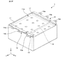
- FIG. 1 is a perspective view schematically showing a capacitor module 1 according to a first embodiment of the present invention.
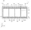
- FIG. 2 is a plan view of the capacitor module 1 of FIG.
- FIG. 3A is a perspective view showing a first capacitor 20 included in the first capacitor group 12 of the capacitor module 1 of FIG.
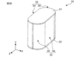
- FIG. 3B is a perspective view showing a second capacitor 30 included in the second capacitor group 13 of the capacitor module 1 of FIG.
- FIG. 4 is a perspective view showing a first bus bar 14 and a second bus bar 15 included in the capacitor module 1 of FIG.
- FIG. 5 is a perspective view showing a third bus bar 16 included in the capacitor module 1 of FIG.
- FIG. 6 is a perspective view showing an insulating member 18 included in the capacitor module 1 of FIG. FIG.
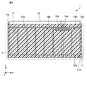
- FIG. 7 is a cross-sectional view of the capacitor module 1 of FIG. 2 in the AA direction.
- FIG. 8 is an enlarged view of a part of FIG. 7.
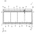
- FIG. 9 is a cross-sectional view of the capacitor module 1 of FIG. 2 in the BB direction.
- FIG. 10 is a cross-sectional view of the capacitor module 1 of FIG. 2 in the CC direction.
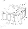
- FIG. 11A is an enlarged perspective view of a part of the capacitor module 1 of FIG.
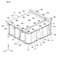
- FIG. 11B is a perspective view in which the insulating member 18 of the capacitor module 1 of FIG. 11A is omitted.
- the X, Y, and Z directions in the drawing indicate the horizontal direction, the height direction, and the vertical direction of the capacitor module 1, respectively.
- the capacitor module 1 includes a case 11, a first capacitor group 12, a second capacitor group 13, a first bus bar 14, a second bus bar 15, and a third bus bar 16. , A sealing resin 17 and an insulating member 18. In FIG. 2, the sealing resin 17 is not shown.
- the case 11 has an opening 11a (see FIG. 1) formed at a position facing the bottom surface 11b (see FIG. 7).
- a first capacitor group 12, a second capacitor group 13, a first bus bar 14, a second bus bar 15, a third bus bar 16, and an insulating member 18 are housed inside the case 11, and the case 11 is sealed.
- the resin 17 is filled.
- the capacitor module 1 is formed so that each of the first bus bar 14, the second bus bar 15, and the third bus bar 16 extends outward along the side surface of the case 11.
- the first bus bar 14, the second bus bar 15, and the third bus bar 16 have terminal portions 14a, 15a, and 16a for connecting external elements and circuits, respectively.
- the first capacitor group 12 is an aggregate of capacitors including a plurality of first capacitors 20 shown in FIG. 3A.
- the second capacitor group 13 is an aggregate of capacitors including one or a plurality of second capacitors 30 shown in FIG. 3B. Since the first capacitor group 12 and the second capacitor group 13 have different functions (for example, capacitance), the capacitor module 1 has two functions. In this embodiment, as shown in FIG. 2, the first capacitor group 12 includes six first capacitors 20, and the second capacitor group 13 includes two second capacitors 30.
- the first capacitor 20 and the second capacitor 30 are wound film capacitors, respectively.
- the first capacitor 20 has a first electrode 21, a second electrode 22, and a side surface 23 connecting the first electrode 21 and the second electrode 22.
- the second capacitor 30 has a third electrode 31, a fourth electrode 32, and a side surface 33 connecting the third electrode 31 and the fourth electrode 32.
- the first bus bar 14 and the second bus bar 15 are arranged on the opening side of the case 11.
- the opening side of the case 11 refers to the side inside the case 11 that is closer to the opening 11a than the bottom surface 11b.
- the first bus bar 14 is connected to the first electrode 21 of each first capacitor 20.
- the second bus bar 15 is connected to the third electrode 31 of each second capacitor 30.
- a plate-shaped third bus bar 16 is arranged on the bottom surface side of the case 11.
- the bottom surface side of the case 11 refers to the side inside the case 11 that is closer to the bottom surface 11b than the opening 11a.
- a first capacitor 20 and a second capacitor 30, respectively, are arranged on the third bus bar 16.
- the second electrode 22 of each first capacitor 20 and the fourth electrode 32 of each second capacitor 30 are connected to the third bus bar 16. That is, each of the first capacitors 20 is arranged so that the first electrode 21 faces the opening side and the second electrode 22 faces the bottom surface side.
- each of the second capacitors 30 is arranged so that the third electrode faces the opening side and the fourth electrode 32 faces the bottom surface side.
- An insulating member 18 is arranged between the first bus bar 14 and the second bus bar 15.
- the insulating member 18 insulates the first electrode 21 and the first bus bar 14 of the first capacitor 20 from the third electrode 31 and the second bus bar 15 of the second capacitor 30.
- the first capacitor 20 is a winding type film capacitor.
- the first capacitor 20 is formed by winding a dielectric film having a metal vapor deposition film formed on its surface and pressing the wound body of the dielectric film into a flat shape. Therefore, as shown in FIG. 2A, the side surface 23 of the first capacitor 20 has a pair of flat portions 24 facing each other and a pair of curved portions 25 connecting the pair of flat portions 24 to each other.
- the dielectric film of the first capacitor 20 for example, a plastic film such as polyethylene terephthalate, polypropylene, polyphenylene sulfide, or polyethylene naphthalate can be used. Further, Al, Zn or the like can be used as the metal vapor deposition film formed on the surface of the plastic film.
- the first electrode 21 and the second electrode 22 are formed by spraying, for example, Zn or the like on the end of the wound dielectric film.
- the first bus bar 14 is a conductive member connected to the first electrode 21 of each of the first capacitors 20 of the first capacitor group 12. As shown in FIG. 4, the first bus bar 14 has a terminal portion 14a connected to an external element or circuit of the capacitor module 1 and an electrode contact portion 14b in contact with each of the first electrodes 21.
- the terminal portion 14a and the electrode contact portion 14b are integrally formed by bending one metal plate.
- the first bus bar 14 is formed of a conductive metal such as Al, Cu, or brass.
- the electrode contact portion 14b is formed with a hole 14c for connecting the first electrodes 21 with solder.
- the terminal portion 14a extends from the electrode contact portion 14b in the height direction (Y direction), and is further bent in the vertical direction (Z direction) in the vicinity of the opening 11a of the case 11.
- the second bus bar 15 is a conductive member connected to the third electrode 31 of each of the second capacitors 30 of the second capacitor group 13. As shown in FIG. 4, the second bus bar 15 has a terminal portion 15a connected to an external element or circuit of the capacitor module 1 and an electrode contact portion 15b in contact with each of the third electrodes 31.
- the terminal portion 15a and the electrode contact portion 15b are integrally formed by bending one metal plate.
- the second bus bar 15 is formed of a conductive metal such as Al, Cu, or brass.
- the electrode contact portion 15b is formed with a hole 15c for connecting each third electrode 31 with solder.
- the terminal portion 15a extends from the electrode contact portion 15b in the height direction (Y direction), and is further bent in the vertical direction (Z direction) in the vicinity of the opening 11a of the case 11.
- the first bus bar 14 and the second bus bar 15 are arranged at intervals d in the lateral direction (X direction) in order to electrically insulate them as shown in FIG. 8 to be described later.
- the third bus bar 16 is connected to the second electrode 22 of each of the first capacitors 20 of the first capacitor group 12 and the fourth electrode 32 of each of the second capacitors 30 of the second capacitor group 13. As shown in FIG. 5, the third bus bar 16 has a terminal portion 16a, an electrode contact portion 16b, and an extending portion 16c.
- the terminal portion 16a is connected to an element or circuit outside the capacitor module 1.
- the electrode contact portion 16b is in common contact with the second electrode 22 and the fourth electrode 32.
- the extending portion 16c extends outward from the electrode contact portion 16b along the side surface of the case 11.
- the terminal portion 16a, the electrode contact portion 16b, and the extending portion 16c are integrally formed by bending a single piece of metal.
- the third bus bar 16 is formed of a conductive metal such as Al, Cu, or brass.
- the electrode contact portion 16b is formed with a hole 16d for connecting the second electrode 22 and the fourth electrode 32, respectively, by soldering.
- the extending portion 16c extends in the height direction (Y direction) from the electrode contact portion 16b, and is bent in the vertical direction (Z direction) near the opening 11a of the case 11.
- a through hole 16e is formed in the extending portion 16c of the third bus bar.
- the through hole 16e is for inserting the insulating member 18 in the ⁇ Y direction.
- the insulating member 18 is a member that insulates the first bus bar 14 and the first electrode 21 and the second bus bar 15 and the third electrode 31.
- the first bus bar 14 and the first electrode 21 and the second bus bar 15 and the third electrode 31 can be more reliably insulated.
- the insulating member 18 has a plate-shaped first portion 18a and a second portion 18b extending so as to intersect the first portion 18a.
- the insulating member 18 is formed of an electrically insulating resin such as polyphenylene sulfide (PPS resin) or polybutylene terephthalate (PBT resin). Since the insulating member 18 is formed by injection molding, it is preferable to use a resin suitable for injection molding.
- the first portion 18a of the insulating member 18 is arranged along between the electrode contact portion 14b of the first bus bar 14 and the electrode contact portion 15b of the second bus bar 15.
- one end 19a of the first portion 18a is an electrode contact portion of the first bus bar 14 in the direction from the opening 11a toward the bottom surface 11b, that is, in the height direction (Y direction). It is located on the opening side of the electrode contact portion 15b of the 14b and the second bus bar 15. Further, the other end 19b of the second portion 18b is located on the bottom surface side of the first electrode 21 and the third electrode 31.
- the distance between the first bus bar 14 and the second bus bar 15 is reduced as compared with the case where the insulating member 18 is not arranged. Insulation distances i1 and i2 between the bus bars can be secured.
- the arrows i1 and i2 shown in FIG. 8 are the insulation distances i1 and i2 between the first bus bar 14 and the first electrode 21 and the second bus bar 15 and the third electrode 31.
- the distance d between the first bus bar 14 and the second bus bar 15 is the insulation distance, so that the distance d must be increased, which makes it difficult to miniaturize the capacitor module 1.
- the insulating member 18 As in the present embodiment, it is possible to secure the insulating distance while reducing the distance d between the first bus bar 14 and the second bus bar 15. Therefore, the first bus bar 14 and the first electrode 21 and the second bus bar 15 and the third electrode 31 can be more reliably insulated.
- the insulation distances i1 and i2 may be set to appropriate values in consideration of the maximum applied voltage of the capacitor groups 12 and 13.
- the insulation distance can be changed by adjusting the positions of one end 19a and the other end 19b of the first portion 18a of the insulating member 18 in the height direction.
- the second portion 18b of the insulating member 18 is the surface 14d of the electrode contact portion 14b of the first bus bar 14 on the side of the first electrode 21 and the second portion 15b of the electrode contact portion 15b of the second bus bar 15. It is located on the bottom surface side of the case 11 with respect to the surface 15d on the 3 electrode 31 side. That is, the second portion 18b of the insulating member 18 is arranged on the lower side of the first bus bar 14 and the second bus bar 15 in the height direction. By arranging the second portion 18b below the first bus bar 14 and the second bus bar 15, it is possible to prevent the insulating member 18 from being lifted by the buoyancy of the sealing resin 17.
- the second portion 18b of the insulating member 18 is arranged between the adjacent curved portions 25 of the adjacent first capacitor 20 and the adjacent curved portions 35 of the adjacent second capacitor 30. .. Since the first capacitor 20 has a curved portion 25, a space is created between the adjacent curved portions 25 of the adjacent first capacitor 20. Similarly, in the case of the second capacitor 30, a space is created between the adjacent curved portions 35.
- the second portion 18b of the insulating member 18 is arranged using this space, the second portion 18b of the insulating member 18 can be arranged without enlarging the case 11, and the insulating member 18 can be insulated while effectively utilizing the space. It is possible to prevent the sex member 18 from rising.
- the first portion 18a of the insulating member 18 is provided with a third portion 18c for preventing misalignment in the horizontal direction including the horizontal direction (X direction) and the vertical direction (Z direction).
- Notches 14e and 15e are provided in the electrode contact portions 14b of the first bus bar 14 and the electrode contact portions 15b of the second bus bar 15, respectively, in order to create a space for arranging the third portion 18c.
- the third portion 18c is arranged so as to be placed on a part of the first electrode 21 and a part of the third electrode 31.
- the third portion 18c of the insulating member 18 is arranged on the upper side of the first capacitor 20 and the second capacitor 30 in the height direction, and is surrounded by the cutouts 14e and 15e so that the insulating member 18 can be placed in the vertical direction ( It is possible to prevent the displacement in the Z direction) or the lateral direction (Z direction).
- the insulating member 18 can be restricted from moving in the + Y direction by the second portion 18b, and can be regulated from moving in the X and Z directions by the third portion 18c.
- the case 11 houses each component of the capacitor module 1.
- the case 11 has an opening 11a formed at a position facing the bottom surface 11b.
- the case 11 has a substantially square opening 11a and a bottom surface 11b, and has a box shape.
- the shape of the case 11 is not limited to this, and various shapes can be taken depending on the arrangement of the capacitor groups.
- the case 11 is formed of, for example, a synthetic resin such as polyphenylene sulfide (PPS resin) or polybutylene terephthalate (PBT resin).
- the case 11 is formed with a protrusion 11c for positioning the insulating member 18.
- the protrusion 11c is a protrusion formed from the inner side surface of the case 11 toward the inside, and forms a recess 11d that receives the first portion 18a of the insulating member 18 in the direction from the opening 11a toward the bottom surface 11b.
- the movement of the protrusion 11c and the insulating member 18 in the lateral direction (X direction) and the vertical direction (Z direction) is restricted. That is, the insulating member 18 is positioned in the X direction and the Z direction by the protrusion 11c.
- the shape of the protrusion 11c is not limited to that shown in FIGS. 11A and 11B, and may be any shape that can hold the end portion of the insulating member 18.
- the movement of the insulating member 18 in the X direction and the Z direction is restricted. Further, the movement of the insulating member 18 in the ⁇ Y direction is also restricted. Since the sealing resin 17 is filled around the insulating member 18, the insulating member 18 is positioned by the protrusion 11c of the case 11 and the sealing resin 17.
- the through hole 16e of the third bus bar 16 overlaps with the protrusion 11c of the case 11.
- the insulating member 18 can be inserted in the direction from the opening 11a toward the bottom surface 11b.
- the bottom surface 11b of the case 11 is flat.
- the sealing resin 17 can easily spread over the entire bottom surface 11b as compared with the case where the bottom surface 11b is provided with a convex portion, so that the filling property of the sealing resin 17 is improved. be able to.
- the sealing resin 17 is filled in the case 11 to seal each component of the capacitor module 1.
- the sealing resin 17 is a thermosetting resin, and for example, an epoxy resin can be used. Alternatively, it may be urethane resin.
- FIGS. 12A to 12F are diagrams showing a manufacturing process of the capacitor module 1 according to the first embodiment.
- the third bus bar 16 can be formed by, for example, pressing a metal plate.
- insulating paper 41 is attached to the extending portion 16c of the third bus bar 16. back.
- the first capacitor 20 and the second capacitor 30 are arranged on the electrode contact portion 16b of the third bus bar 16, respectively. Specifically, as shown in FIG. 12A, the first capacitor 20 and the second capacitor 30, respectively, are arranged so that the second electrode 22 and the fourth electrode 32 face the electrode contact portion 16b.
- the insulating member 18 is arranged. Specifically, as shown in FIG. 12B, the first portion 18a of the insulating member 18 is arranged between the first capacitor group 12 and the second capacitor group 13. At this time, the second portion 18b is located between the curved portions 25 of the first capacitor 20 and between the curved portions 35 of the second capacitor 30. Further, the third portion 18c is placed on the first capacitor 20 and the second capacitor 30.
- the first portion 18a of the insulating member 18 is arranged so as to be sandwiched between the first capacitor group 12 and the second capacitor group 13, and lateral movement is possible. Be regulated. Further, at this time, since the end portion of the first portion 18a passes through the through hole 16e of the third bus bar, the first portion 18a and the third bus bar 16 do not interfere with each other.
- the insulating member 18 is not in a fixed state, but is arranged so that the end portion of the insulating member 18 can be fitted into the recess 11d in the step of inserting each component described later into the case 11. ing.
- the second portion 18b is located in the ⁇ Y direction with respect to the first electrode 21 and the third electrode 31, the insulating member 18 is in a state of being movable in the Y direction, so that the insulating member 18 is fitted into the recess 11d.
- the combination can be easily performed.
- the first bus bar 14 and the second bus bar 15 are arranged. Specifically, as shown in FIG. 12C, the electrode contact portion 14b of the first bus bar 14 is placed on the first electrode 21 of each first capacitor 20 of the first capacitor group 12. Further, the electrode contact portion 15b of the second bus bar 15 is placed on the third electrode 31 of each of the second capacitors 30 of the second capacitor group 13. At this time, the first bus bar 14 and the second bus bar 15 are arranged so that the third portion 18c of the insulating member 18 is located in the notches 14e and 15e of the first bus bar 14 and the second bus bar 15, respectively. ..
- the electrode contact portion 14b and each of the first electrodes 21 are connected by soldering (not shown). Further, in the hole 15c of the electrode contact portion 15b of the second bus bar 15, the electrode contact portion 15b and each of the third electrodes 31 are connected by solder (not shown). By soldering, the first bus bar 14 and each of the first electrodes 21 and the second bus bar 15 and each of the third electrodes 31 can be electrically connected.
- the third bus bar 16 is connected to the second electrode 22 and the fourth electrode 32, respectively, by soldering (not shown). Specifically, as shown in FIG. 12D, the third bus bar 16, the second electrode 22, and the fourth electrode are soldered in the holes 16d provided in the electrode contact portion 16b of the third bus bar 16. It is electrically connected to 32.
- the soldered first capacitor 20, the second capacitor 30, the first bus bar 14, the second bus bar 15, the third bus bar 16, and the insulating member 18 are attached to the case 11. insert.
- the end portion of the first portion 18a of the insulating member 18 is inserted into the recess 11d of the protrusion 11c of the case 11 (see FIG. 11A).
- the insulating member 18 is positioned in the X direction and the Z direction inside the case 11.
- the case 11 After being inserted into the case 11, as shown in FIG. 12F, the case 11 is filled with the sealing resin 17 and the sealing resin 17 is cured to complete the capacitor module 1. At this time, the second portion 18b of the insulating member 18 is restricted from moving in the + Y direction by the first bus bar 14 and the second bus bar 15 (see FIG. 9). Therefore, it is possible to prevent the insulating member 18 from floating when the sealing resin 17 is filled. Further, since the bottom surface 11b of the case 11 is formed flat, the filling property of the sealing resin 17 is improved.
- the capacitor module 1 includes a case 11, a first capacitor group 12, a second capacitor group 13, a first bus bar 14, a second bus bar 15, a third bus bar 16, a sealing resin 17, and an insulating member. It is provided with 18.
- the case 11 has an opening 11a formed at a position facing the bottom surface 11b.
- the first capacitor group 12 includes one or more first capacitors 20.
- the first capacitor 20 is arranged inside the case 11 and has a first electrode 21, a second electrode 22, and a side surface 23 connecting the first electrode 21 and the second electrode 22.
- the second capacitor group 13 includes one or more second capacitors 30.
- the second capacitor 30 is arranged inside the case 11 and has a third electrode 31, a fourth electrode 32, and a side surface 23 connecting the third electrode 31 and the fourth electrode 32.
- the first bus bar 14 is arranged inside the case 11 on the opening 11a side with respect to the first capacitor group 12, and has an electrode contact portion 14b that contacts the first electrode 21.
- the second bus bar 15 is arranged inside the case 11 on the opening 11a side with respect to the second capacitor group 13, and has an electrode contact portion 15b that contacts the third electrode 31.
- the third bus bar 16 is arranged on the bottom surface 11b side with respect to the first capacitor group 12 and the second capacitor group 13 inside the case 11, and is in common contact with the second electrode 22 and the fourth electrode 32. It has a part 16b.
- the sealing resin 17 is filled in the case 11.
- the insulating member 18 is provided between the electrode contact portion 14b of the first bus bar 14 and the electrode contact portion 15b of the second bus bar 15, and is surrounded by the sealing resin 17.
- the first bus bar 14, the first electrode 21, and the second bus bar 15 are compared with the case where the insulating member 18 is not arranged and only the sealing resin 17 is provided. And the insulation property with the third electrode 31 can be improved.
- the insulating member 18 is not arranged, it is insulated by the sealing resin 17, but there is a risk of insulation failure due to air bubbles generated in the sealing resin 17.
- the first bus bar 14 and the first electrode 21 and the second bus bar 15 and the third electrode 31 can be reliably insulated, and the insulating property can be improved. improves.
- the insulating member 18 By arranging the insulating member 18, long insulation distances i1 and i2 are secured while reducing the distance d between the first bus bar 14 and the first electrode 21 and the second bus bar 15 and the third electrode 31. be able to. Therefore, the distance d between the first bus bar 14 and the first electrode 21 and the second bus bar 15 and the third electrode 31 can be reduced, which contributes to the miniaturization of the capacitor module 1.
- one end 19a of the insulating member 18 opens the case 11 more than the electrode contact portion 14b of the first bus bar 14 and the electrode contact portion 15b of the second bus bar 15 in the direction from the opening 11a toward the bottom surface 11b.
- the other end 19b of the insulating member 18 is located on the bottom surface side of the case 11 with respect to the first electrode 21 and the third electrode 31.
- the insulation distances of the first bus bar 14 and the second bus bar 15 can be changed depending on the positions of the ends 19a and 19b of the insulating member 18 in the height direction (Y direction).
- Y direction the height direction
- the insulation distance i1 becomes longer.
- the position of the other end 19b of the insulating member 18 in the height direction is located below FIG. 8 (-Y direction)
- the insulation distance i2 becomes longer.
- the lengths of the insulation distances i1 and i2 may be appropriately set according to the capacitance of the capacitor module 1 and the like.
- the insulating distance is the electrode contact portion 14b.
- the distance d from the electrode contact portion 15b in order to secure an appropriate insulation distance, the distance d is increased, which makes it difficult to reduce the size of the capacitor module 1.
- the insulation distance is determined by the first electrode 21 and the third electrode 31.
- the distance d from the third electrode 31 in this case as well, the distance d is increased in order to secure an appropriate insulation distance.
- a protrusion 11c is formed on the inner surface of the case 11 to have a recess 11d that receives the insulating member 18 in the direction from the opening 11a toward the bottom surface 11b, and to position the insulating member 18.
- the third bus bar 16 further has an extending portion 16c extending from the electrode contact portion 16b of the third bus bar 16 to the outside of the case 11 through the opening 11a along the side surface of the case 11.
- a through hole 16e through which the insulating member 18 is passed is formed in the extending portion 16c.
- the insulating member 18 has a first portion 18a and a second portion 18b.
- the first portion 18a extends along between the electrode contact portion 14b of the first bus bar 14 and the electrode contact portion 15b of the second bus bar 15.
- the second portion 18b extends so as to intersect the first portion 18a, and the surface 14d of the electrode contact portion 14b of the first bus bar 14 on the side of the first electrode 21 and the electrode contact portion 15b of the second bus bar 15. It extends so as to be located on the bottom surface side of the case 11 with respect to the surface 15d on the third electrode 31 side. With such a configuration, it is possible to prevent the insulating member 18 from being lifted by the buoyancy of the sealing resin 17.
- the side surface 23 of the first capacitor 20 has a pair of flat portions 24 facing each other and a pair of curved portions 25 connecting the pair of flat portions 24 to each other.
- the side surface 33 of the second capacitor 30 has a pair of flat portions 34 and a pair of curved portions 35 connecting the pair of flat portions 34 to each other.
- the second portion 18b of the insulating member 18 is arranged between the adjacent curved portions 25 of the adjacent first capacitor 20 and between the adjacent curved portions 35 of the adjacent second capacitor 30. With such a configuration, the second portion 18b can be arranged in the space formed between the adjacent curved portions 25 and the adjacent curved portions 35, which contributes to the miniaturization of the capacitor module 1.
- the bottom surface 11b of the case 11 is flat. With such a configuration, the filling property of the sealing resin 17 can be improved.
- the bottom surface 11b of the case 11 is flat, the fluidity of the resin is improved, so that the flow of the resin when filling the case with the resin is blocked, which reduces the time required for the resin filling process and increases the manufacturing cost. It is possible to prevent it from being lost.
- the case 11 can be easily manufactured, so that the size can be reduced, which contributes to the miniaturization of the capacitor module 1.
- the present invention is not limited to this.
- the second portion 18b may extend to either the first capacitor group 12 side or the second capacitor group 13 side. Further, the second portion 18b may be provided at two or more places.
- the insulating member 18 is provided with the second portion 18b and the third portion 18c has been described, but the second portion 18b and the third portion 18c may not be provided.
- the notches 14e and 15e of the first bus bar 14 and the second bus bar 15, respectively may not be formed.
- the insulating member 18 is positioned by the protrusion 11c of the case 11, but not limited to such a case, as shown in FIGS. 13A and 13B, the insulating member 18 is formed in the through hole of the third bus bar 16. May be positioned.
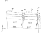
- FIG. 13A is an enlarged perspective view of a part of the capacitor module 1a according to the modified example of the first embodiment of the present invention.
- FIG. 13B is a perspective view in which the insulating member 18 of the capacitor module 1a of FIG. 13A is omitted.
- the sealing resin 17 is omitted.
- the insulating member 18 is formed at one end on the bottom surface side of the through hole 16f formed in the extending portion 16c. It is received by the bus bar 16 and positioned.
- the through hole 16f is formed with a portion whose width decreases from the opening side toward the bottom surface side and a portion having a substantially constant width similar to that of the insulating member 18.
- the insulating member 18 is positioned at a portion having a certain width. Therefore, when the insulating member 18 is inserted from the opening side to the bottom surface side, the insulating member 18 is positioned in the lateral direction (X direction).
- the insulating member 18 can be positioned with a simple configuration, and the manufacturing cost is reduced. Can be reduced. Further, when the through hole 16f as shown in FIGS. 13A and 13B is provided, the insulating member 18 is already positioned in the state of FIG. 12B. Therefore, as shown in FIG. 12E, it is possible to prevent the insulating member 18 from being displaced with respect to the bus bar or the capacitor when it is inserted into the case 11. Therefore, the positioning accuracy of the insulating member 18 is improved, and the insulating property can be improved.
- the second embodiment mainly describes the differences from the first embodiment.
- the same or equivalent configurations as those in the first embodiment will be described with the same reference numerals. Further, in the second embodiment, the description overlapping with the first embodiment is omitted.
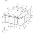
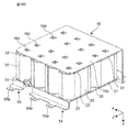
- FIG. 14 is a perspective view in which the case and the sealing resin of the capacitor module 1b according to the second embodiment are omitted.
- FIG. 15 is an enlarged view of the region R1 of the capacitor module 1b of FIG.
- FIG. 16 is a diagram showing an insulating member 58 of the capacitor module 1b of FIG.
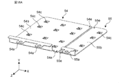
- FIG. 17 is a diagram showing a first bus bar 54 and a second bus bar 55 of the capacitor module 1b of FIG.
- the second portion 58b of the insulating member 58 has a protrusion 58c, and the protrusion 58c is provided on each of the first bus bar 54 and the second bus bar 55, respectively. It differs from the first embodiment in that it is inserted into the holes 54e and 55e (see FIG. 17).
- the insulating member 58 has two second portions 58b at both ends of the first portion 58a. That is, four second portions 58b are formed in the first portion 58a. Further, a protrusion 58c is formed from each second portion 58b of the insulating member 58 in the + Y direction. The tip of the protrusion 58c is formed in a hook shape.
- holes 54e and 55e are formed in the first bus bar 54 and the second bus bar 55, respectively.
- the hook portion of the protrusion 58c is caught in the hole 54e or 55e. It is fixed. That is, each of the protrusion 58c and the hole 54e or 55e is fitted by snap-fitting. In this way, the insulating member 58 is joined to the first bus bar 54 and the second bus bar 55.
- the insulating member 58 is joined to and positioned with the first bus bar 54 and the second bus bar 55. Therefore, the case 11 and the third bus bar 16 are not formed with protrusions or through holes for positioning the insulating member 58. Further, since the insulating member 18, the first bus bar 54, and the second bus bar 55 are fitted by snap-fitting, the insulating member 58 has a portion for preventing lifting (second portion 18b of the first embodiment). ) Is not provided, and the configuration is simpler than that of the first embodiment.
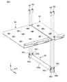
- FIGS. 18A to 18F are diagrams showing a manufacturing process of the capacitor module 1b according to the second embodiment.
- the first bus bar 54 and the second bus bar 55 are prepared.
- the first bus bar 54 is formed with an electrode contact portion 54b, a terminal portion 54a, a hole 54c for soldering, and a hole 54e for joining with the insulating member 58.
- the second bus bar 55 is formed with an electrode contact portion 55b, a terminal portion 55a, a hole 55c for soldering, and a hole 55e for joining with the insulating member 58.
- the protrusion 58c of the insulating member 58 is inserted into the hole 54e of the first bus bar 54 and the hole 55e of the second bus bar 55.
- Each of the protrusions 58c of the insulating member 58 is inserted in the direction (Y direction) from the bottom surface 11b of the case 11 toward the opening 11a. Since the insulating member 58 is joined to the first bus bar 54 and the second bus bar 55 by snap-fitting, the insulating member 58 can be firmly fixed to the first bus bar 54 and the second bus bar 55.
- the electrode contact portion 54b of the first bus bar 54 and the electrode contact portion 15b of the second bus bar 55 are kept substantially in the same plane. Can be fixed while.
- each of the first capacitor 20 and the second capacitor 30 is arranged at the electrode contact portion 16b of the third bus bar 16.
- the first bus bar 54 and the second bus bar 55 joined to the insulating member 58 in FIG. 18B are arranged on the first capacitor 20 and the second capacitor 30.
- the insulating member 58 does not have to be arranged in the through hole of the third bus bar 16, and the first bus bar 54 and the second bus bar 55 are kept substantially in the same plane. , Can be easily placed.
- first bus bar 54 and the second bus bar 55 After arranging the first bus bar 54 and the second bus bar 55, the first bus bar 54 and the first electrode 21 of each of the first capacitors 20 and the second bus bar 55 and the third electrode 31 of each second capacitor 30 are placed. Connect by solder (not shown). The first bus bar 54 and each of the first electrodes 21 are electrically connected by soldering in the holes 54c provided in the electrode contact portion 54b of the first bus bar 54. Similarly, both the second bus bar 55 and the third electrode 31 are electrically soldered to the second bus bar 55 and the third electrode 31 by soldering them in the holes 55c provided in the electrode contact portion 55b of the second bus bar 55. Connect to.
- the third bus bar 16 and the respective second electrodes 22 and fourth electrodes 32 are connected by solder (not shown).
- the third bus bar 16 is electrically connected to the second electrode 22 and the fourth electrode 32 by soldering in the hole 16d provided in the electrode contact portion 16b of the third bus bar 16.
- the soldered first capacitor 20, second capacitor 30, first bus bar 54, second bus bar 55, third bus bar 16, and insulating member 58 are inserted into the case 11. At this time, no protrusion is formed on the case 11, and the insulating member 58 and the case 11 do not need to be aligned with each other, so that the case 11 can be easily arranged.
- the case 11 After being inserted into the case 11, as shown in FIG. 18G, the case 11 is filled with the sealing resin 17 and the sealing resin 17 is cured to complete the capacitor module 1b. At this time, the protrusions 58c of the insulating member 58 are inserted into the holes 54e and 55e, respectively. Therefore, it is possible to prevent the insulating member 58 from being lifted by the buoyancy of the sealing resin 17 without separately providing a lift prevention structure (second portion 18b of the first embodiment) of the insulating member 58.
- the second portion 58b of the insulating member 58 of the capacitor module 1b has a protrusion 58c and is inserted into holes 54e and 55e provided in the first bus bar 54 and the second bus bar 55, respectively.
- the capacitor module 1c according to the modified example of the second embodiment will be described with reference to FIGS. 19 to 21.
- FIG. 19 is a perspective view in which the case and the sealing resin of the capacitor module 1c according to the modified example of the second embodiment are omitted.
- FIG. 20 is an enlarged view of the region R2 of the capacitor module 1c of FIG.
- FIG. 21 is a diagram showing a first bus bar 64, a second bus bar 65, and an insulating member 68 of the capacitor module 1c of FIG.
- the insulating member 58 and the first bus bar 54 and the second bus bar 55 are joined by a snap-fit structure, but in the capacitor module 1c, they are joined by screws.
- the insulating member 68 and the first bus bar 64 and the second bus bar 65 are joined by four screws 69.
- the second portion 68b of the insulating member 68 has a recess 68c.
- circular holes 64e and 65e are provided in the first bus bar 64 and the second bus bar 65, respectively.
- the capacitor module 1c further has screws 69 to be inserted into holes 64e and 65e and recesses 68c provided in the first bus bar 64 and the second bus bar 65, respectively.
- the insulating member 68, the first bus bar 64, and the second bus bar 65 can be fixed more firmly than the snap fit. Further, the positioning accuracy of the insulating member 68 can be improved.
- the present invention is useful for capacitors used in various electronic devices, electrical devices, industrial devices, vehicle devices, and the like.
Landscapes
- Engineering & Computer Science (AREA)
- Power Engineering (AREA)
- Microelectronics & Electronic Packaging (AREA)
- Manufacturing & Machinery (AREA)
- Fixed Capacitors And Capacitor Manufacturing Machines (AREA)
Priority Applications (4)
| Application Number | Priority Date | Filing Date | Title |
|---|---|---|---|
| EP21797156.3A EP4120298A4 (en) | 2020-04-28 | 2021-04-21 | Capacitor module |
| CN202180030683.3A CN115485797B (zh) | 2020-04-28 | 2021-04-21 | 电容器模块 |
| JP2022517676A JP7409491B2 (ja) | 2020-04-28 | 2021-04-21 | コンデンサモジュール |
| US17/971,840 US12537141B2 (en) | 2020-04-28 | 2022-10-24 | Capacitor module and a method of making thereof with plurality of bus bars |
Applications Claiming Priority (2)
| Application Number | Priority Date | Filing Date | Title |
|---|---|---|---|
| JP2020079431 | 2020-04-28 | ||
| JP2020-079431 | 2020-04-28 |
Related Child Applications (1)
| Application Number | Title | Priority Date | Filing Date |
|---|---|---|---|
| US17/971,840 Continuation US12537141B2 (en) | 2020-04-28 | 2022-10-24 | Capacitor module and a method of making thereof with plurality of bus bars |
Publications (1)
| Publication Number | Publication Date |
|---|---|
| WO2021220918A1 true WO2021220918A1 (ja) | 2021-11-04 |
Family
ID=78331953
Family Applications (1)
| Application Number | Title | Priority Date | Filing Date |
|---|---|---|---|
| PCT/JP2021/016214 Ceased WO2021220918A1 (ja) | 2020-04-28 | 2021-04-21 | コンデンサモジュール |
Country Status (5)
| Country | Link |
|---|---|
| US (1) | US12537141B2 (https=) |
| EP (1) | EP4120298A4 (https=) |
| JP (1) | JP7409491B2 (https=) |
| CN (1) | CN115485797B (https=) |
| WO (1) | WO2021220918A1 (https=) |
Cited By (2)
| Publication number | Priority date | Publication date | Assignee | Title |
|---|---|---|---|---|
| JP2023136320A (ja) * | 2022-03-16 | 2023-09-29 | 株式会社指月電機製作所 | コンデンサ及びコンデンサの製造方法 |
| US20250201484A1 (en) * | 2022-06-29 | 2025-06-19 | Nichicon Corporation | Capacitor |
Families Citing this family (1)
| Publication number | Priority date | Publication date | Assignee | Title |
|---|---|---|---|---|
| JP7832055B2 (ja) * | 2022-05-30 | 2026-03-17 | Tdk株式会社 | 電子部品 |
Citations (10)
| Publication number | Priority date | Publication date | Assignee | Title |
|---|---|---|---|---|
| JPS60721A (ja) * | 1983-06-16 | 1985-01-05 | 利昌工業株式会社 | コンデンサ容器 |
| JP2000195748A (ja) * | 1998-12-25 | 2000-07-14 | Matsushita Electric Ind Co Ltd | コンデンサ |
| JP2001210548A (ja) | 2000-01-24 | 2001-08-03 | Nichicon Corp | 複合型乾式金属化フィルムコンデンサ |
| JP2006216618A (ja) * | 2005-02-01 | 2006-08-17 | Shizuki Electric Co Inc | ケース入りコンデンサ |
| JP2007311634A (ja) * | 2006-05-19 | 2007-11-29 | Toyota Motor Corp | コンデンサおよび電気機器ならびに車両 |
| JP2008130640A (ja) * | 2006-11-17 | 2008-06-05 | Matsushita Electric Ind Co Ltd | ケースモールド型コンデンサ |
| JP2010219259A (ja) * | 2009-03-17 | 2010-09-30 | Denso Corp | コンデンサモジュール |
| JP2017045955A (ja) * | 2015-08-28 | 2017-03-02 | アール・ビー・コントロールズ株式会社 | 回路基板のポッティング方法 |
| JP2017195285A (ja) * | 2016-04-20 | 2017-10-26 | 株式会社指月電機製作所 | 外部端子構造及び樹脂モールド型コンデンサ |
| JP2018170410A (ja) * | 2017-03-30 | 2018-11-01 | ニチコン株式会社 | コンデンサ装置 |
Family Cites Families (23)
| Publication number | Priority date | Publication date | Assignee | Title |
|---|---|---|---|---|
| JP3975993B2 (ja) * | 2003-09-29 | 2007-09-12 | 松下電器産業株式会社 | ケースモールド型フィルムコンデンサ |
| JP4923589B2 (ja) * | 2006-01-26 | 2012-04-25 | パナソニック株式会社 | ケースモールド型コンデンサ |
| JP4630245B2 (ja) * | 2006-08-09 | 2011-02-09 | シャープ株式会社 | 加湿装置 |
| US8194393B2 (en) * | 2007-02-16 | 2012-06-05 | Panasonic Corporation | Capacitor unit and its manufacturing method |
| US8315031B2 (en) * | 2007-10-12 | 2012-11-20 | Panasonic Corporation | Case mold type capacitor |
| KR101098297B1 (ko) * | 2010-03-08 | 2011-12-23 | 주식회사 뉴인텍 | 커패시터 모듈 |
| FR2987933B1 (fr) * | 2012-03-09 | 2014-03-07 | Batscap Sa | Dispositif d'isolation pour isoler electriquement les uns des autres une pluralite d'ensembles de stockage d'energie |
| KR101273255B1 (ko) * | 2012-08-14 | 2013-06-11 | 주식회사 뉴인텍 | 케이스 탑재형 직렬형 커패시터 |
| JP6425024B2 (ja) * | 2015-02-16 | 2018-11-21 | パナソニックIpマネジメント株式会社 | コンデンサおよびインバータ |
| CN204407189U (zh) * | 2015-03-17 | 2015-06-17 | 常州常捷科技有限公司 | 一种金属化膜滤波电容器 |
| CN104766722B (zh) * | 2015-03-17 | 2018-04-13 | 常州常捷科技有限公司 | 具有低电感低等效串联电阻特性的金属化膜滤波电容器 |
| JP6376405B2 (ja) * | 2015-05-28 | 2018-08-22 | 豊田合成株式会社 | 電池モジュール |
| CN109155195B (zh) * | 2016-05-25 | 2020-10-30 | 松下知识产权经营株式会社 | 电容器 |
| CN107527741B (zh) * | 2016-06-15 | 2019-12-13 | 株式会社村田制作所 | 固体电解电容器 |
| CN109478461B (zh) * | 2016-07-21 | 2021-06-18 | 松下知识产权经营株式会社 | 电容器 |
| WO2018074138A1 (ja) * | 2016-10-20 | 2018-04-26 | パナソニックIpマネジメント株式会社 | コンデンサ |
| WO2018198527A1 (ja) * | 2017-04-26 | 2018-11-01 | パナソニックIpマネジメント株式会社 | コンデンサ |
| WO2019026605A1 (ja) * | 2017-08-02 | 2019-02-07 | パナソニックIpマネジメント株式会社 | コンデンサ |
| WO2019225187A1 (ja) * | 2018-05-25 | 2019-11-28 | パナソニックIpマネジメント株式会社 | コンデンサ |
| JP7175721B2 (ja) * | 2018-11-12 | 2022-11-21 | ニチコン株式会社 | フィルムコンデンサの成形方法およびその成形型枠 |
| CN119400594A (zh) * | 2019-02-05 | 2025-02-07 | 松下知识产权经营株式会社 | 电容器 |
| JP2020167215A (ja) * | 2019-03-28 | 2020-10-08 | 株式会社デンソー | コンデンサユニット |
| JP7221761B2 (ja) * | 2019-03-29 | 2023-02-14 | ニチコン株式会社 | ケースモールド型コンデンサ |
-
2021
- 2021-04-21 CN CN202180030683.3A patent/CN115485797B/zh active Active
- 2021-04-21 JP JP2022517676A patent/JP7409491B2/ja active Active
- 2021-04-21 EP EP21797156.3A patent/EP4120298A4/en active Pending
- 2021-04-21 WO PCT/JP2021/016214 patent/WO2021220918A1/ja not_active Ceased
-
2022
- 2022-10-24 US US17/971,840 patent/US12537141B2/en active Active
Patent Citations (10)
| Publication number | Priority date | Publication date | Assignee | Title |
|---|---|---|---|---|
| JPS60721A (ja) * | 1983-06-16 | 1985-01-05 | 利昌工業株式会社 | コンデンサ容器 |
| JP2000195748A (ja) * | 1998-12-25 | 2000-07-14 | Matsushita Electric Ind Co Ltd | コンデンサ |
| JP2001210548A (ja) | 2000-01-24 | 2001-08-03 | Nichicon Corp | 複合型乾式金属化フィルムコンデンサ |
| JP2006216618A (ja) * | 2005-02-01 | 2006-08-17 | Shizuki Electric Co Inc | ケース入りコンデンサ |
| JP2007311634A (ja) * | 2006-05-19 | 2007-11-29 | Toyota Motor Corp | コンデンサおよび電気機器ならびに車両 |
| JP2008130640A (ja) * | 2006-11-17 | 2008-06-05 | Matsushita Electric Ind Co Ltd | ケースモールド型コンデンサ |
| JP2010219259A (ja) * | 2009-03-17 | 2010-09-30 | Denso Corp | コンデンサモジュール |
| JP2017045955A (ja) * | 2015-08-28 | 2017-03-02 | アール・ビー・コントロールズ株式会社 | 回路基板のポッティング方法 |
| JP2017195285A (ja) * | 2016-04-20 | 2017-10-26 | 株式会社指月電機製作所 | 外部端子構造及び樹脂モールド型コンデンサ |
| JP2018170410A (ja) * | 2017-03-30 | 2018-11-01 | ニチコン株式会社 | コンデンサ装置 |
Non-Patent Citations (1)
| Title |
|---|
| See also references of EP4120298A4 |
Cited By (2)
| Publication number | Priority date | Publication date | Assignee | Title |
|---|---|---|---|---|
| JP2023136320A (ja) * | 2022-03-16 | 2023-09-29 | 株式会社指月電機製作所 | コンデンサ及びコンデンサの製造方法 |
| US20250201484A1 (en) * | 2022-06-29 | 2025-06-19 | Nichicon Corporation | Capacitor |
Also Published As
| Publication number | Publication date |
|---|---|
| JP7409491B2 (ja) | 2024-01-09 |
| CN115485797A (zh) | 2022-12-16 |
| EP4120298A1 (en) | 2023-01-18 |
| EP4120298A4 (en) | 2024-05-22 |
| US12537141B2 (en) | 2026-01-27 |
| US20230038001A1 (en) | 2023-02-09 |
| JPWO2021220918A1 (https=) | 2021-11-04 |
| CN115485797B (zh) | 2025-03-11 |
Similar Documents
| Publication | Publication Date | Title |
|---|---|---|
| US6084294A (en) | Semiconductor device comprising stacked semiconductor elements | |
| JP7409491B2 (ja) | コンデンサモジュール | |
| KR100464217B1 (ko) | 칩형 공통 모드 초크 코일 | |
| JP5897918B2 (ja) | コンデンサ | |
| JPWO2021220918A5 (https=) | ||
| US10175269B2 (en) | Current detector | |
| JP2008277474A (ja) | ケース入りコンデンサ | |
| KR101020528B1 (ko) | 적층 콘덴서 | |
| JP2011155138A (ja) | コンデンサ | |
| US10984952B2 (en) | Capacitor | |
| CN101176172A (zh) | 层叠型固体电解电容器及其制造方法 | |
| JP5045343B2 (ja) | コンデンサ | |
| JP4396734B2 (ja) | 表面実装型電子部品 | |
| US12340943B2 (en) | Electronic device | |
| JP3080880B2 (ja) | チップ型固体電解コンデンサ | |
| JP6960984B2 (ja) | 電子装置及びその絶縁部材 | |
| US10460872B2 (en) | Electronic device | |
| JP2697001B2 (ja) | チップ型固体電解コンデンサ | |
| US20200267840A1 (en) | Switching device and electronic device | |
| CN113410023A (zh) | 电感部件 | |
| JP7700840B2 (ja) | コンデンサモジュール | |
| CN223450676U (zh) | 端子粘接稳定的半磁件及电磁器件 | |
| JP2001102244A (ja) | チップ形コンデンサ | |
| JP2018147909A (ja) | コンデンサ | |
| US20190371529A1 (en) | Electronic component |
Legal Events
| Date | Code | Title | Description |
|---|---|---|---|
| 121 | Ep: the epo has been informed by wipo that ep was designated in this application |
Ref document number: 21797156 Country of ref document: EP Kind code of ref document: A1 |
|
| ENP | Entry into the national phase |
Ref document number: 2021797156 Country of ref document: EP Effective date: 20221010 |
|
| ENP | Entry into the national phase |
Ref document number: 2022517676 Country of ref document: JP Kind code of ref document: A |
|
| NENP | Non-entry into the national phase |
Ref country code: DE |
|
| WWG | Wipo information: grant in national office |
Ref document number: 202180030683.3 Country of ref document: CN |