WO2021220752A1 - Dispositif d'usinage et procédé de fixation d'une machine-outil à un dispositif d'usinage - Google Patents
Dispositif d'usinage et procédé de fixation d'une machine-outil à un dispositif d'usinage Download PDFInfo
- Publication number
- WO2021220752A1 WO2021220752A1 PCT/JP2021/014826 JP2021014826W WO2021220752A1 WO 2021220752 A1 WO2021220752 A1 WO 2021220752A1 JP 2021014826 W JP2021014826 W JP 2021014826W WO 2021220752 A1 WO2021220752 A1 WO 2021220752A1
- Authority
- WO
- WIPO (PCT)
- Prior art keywords
- processing
- entrance
- grinding
- exterior cover
- shutter
- Prior art date
Links
Images


Classifications
-
- B—PERFORMING OPERATIONS; TRANSPORTING
- B23—MACHINE TOOLS; METAL-WORKING NOT OTHERWISE PROVIDED FOR
- B23Q—DETAILS, COMPONENTS, OR ACCESSORIES FOR MACHINE TOOLS, e.g. ARRANGEMENTS FOR COPYING OR CONTROLLING; MACHINE TOOLS IN GENERAL CHARACTERISED BY THE CONSTRUCTION OF PARTICULAR DETAILS OR COMPONENTS; COMBINATIONS OR ASSOCIATIONS OF METAL-WORKING MACHINES, NOT DIRECTED TO A PARTICULAR RESULT
- B23Q11/00—Accessories fitted to machine tools for keeping tools or parts of the machine in good working condition or for cooling work; Safety devices specially combined with or arranged in, or specially adapted for use in connection with, machine tools
- B23Q11/08—Protective coverings for parts of machine tools; Splash guards
- B23Q11/0891—Protective coverings for parts of machine tools; Splash guards arranged between the working area and the operator
-
- B—PERFORMING OPERATIONS; TRANSPORTING
- B23—MACHINE TOOLS; METAL-WORKING NOT OTHERWISE PROVIDED FOR
- B23Q—DETAILS, COMPONENTS, OR ACCESSORIES FOR MACHINE TOOLS, e.g. ARRANGEMENTS FOR COPYING OR CONTROLLING; MACHINE TOOLS IN GENERAL CHARACTERISED BY THE CONSTRUCTION OF PARTICULAR DETAILS OR COMPONENTS; COMBINATIONS OR ASSOCIATIONS OF METAL-WORKING MACHINES, NOT DIRECTED TO A PARTICULAR RESULT
- B23Q3/00—Devices holding, supporting, or positioning work or tools, of a kind normally removable from the machine
- B23Q3/155—Arrangements for automatic insertion or removal of tools, e.g. combined with manual handling
- B23Q3/157—Arrangements for automatic insertion or removal of tools, e.g. combined with manual handling of rotary tools
-
- B—PERFORMING OPERATIONS; TRANSPORTING
- B24—GRINDING; POLISHING
- B24B—MACHINES, DEVICES, OR PROCESSES FOR GRINDING OR POLISHING; DRESSING OR CONDITIONING OF ABRADING SURFACES; FEEDING OF GRINDING, POLISHING, OR LAPPING AGENTS
- B24B45/00—Means for securing grinding wheels on rotary arbors
-
- B—PERFORMING OPERATIONS; TRANSPORTING
- B24—GRINDING; POLISHING
- B24B—MACHINES, DEVICES, OR PROCESSES FOR GRINDING OR POLISHING; DRESSING OR CONDITIONING OF ABRADING SURFACES; FEEDING OF GRINDING, POLISHING, OR LAPPING AGENTS
- B24B55/00—Safety devices for grinding or polishing machines; Accessories fitted to grinding or polishing machines for keeping tools or parts of the machine in good working condition
- B24B55/06—Dust extraction equipment on grinding or polishing machines
-
- H—ELECTRICITY
- H01—ELECTRIC ELEMENTS
- H01L—SEMICONDUCTOR DEVICES NOT COVERED BY CLASS H10
- H01L21/00—Processes or apparatus adapted for the manufacture or treatment of semiconductor or solid state devices or of parts thereof
- H01L21/02—Manufacture or treatment of semiconductor devices or of parts thereof
- H01L21/04—Manufacture or treatment of semiconductor devices or of parts thereof the devices having at least one potential-jump barrier or surface barrier, e.g. PN junction, depletion layer or carrier concentration layer
- H01L21/18—Manufacture or treatment of semiconductor devices or of parts thereof the devices having at least one potential-jump barrier or surface barrier, e.g. PN junction, depletion layer or carrier concentration layer the devices having semiconductor bodies comprising elements of Group IV of the Periodic System or AIIIBV compounds with or without impurities, e.g. doping materials
- H01L21/30—Treatment of semiconductor bodies using processes or apparatus not provided for in groups H01L21/20 - H01L21/26
- H01L21/302—Treatment of semiconductor bodies using processes or apparatus not provided for in groups H01L21/20 - H01L21/26 to change their surface-physical characteristics or shape, e.g. etching, polishing, cutting
- H01L21/304—Mechanical treatment, e.g. grinding, polishing, cutting
Definitions
- This disclosure relates to a processing device and a method of attaching a processing tool of the processing device.
- the grinding means described in Patent Document 1 includes a spindle, a wheel mount arranged at the lower end of the spindle, and a grinding wheel detachably attached to the lower surface of the wheel mount.
- the grinding wheel includes an annular wheel base and a plurality of grinding wheels arranged in an annular shape on the lower surface of the wheel base. The operator attaches the wheel base to the underside of the wheel mount with fastening bolts.
- One aspect of the present disclosure provides a technique for preventing an operator from becoming dirty when exchanging a processing tool and suppressing particles such as processing chips from flowing out to the outside.
- the processing apparatus includes a holding portion for holding the processing body, a processing mechanism in which a processing tool for processing the processing body held in the holding portion is interchangeably attached, and the holding portion.
- An exterior cover for accommodating the processing mechanism is provided.
- the exterior cover has an entrance through which the processing tool changing device passes from the outside to the inside of the exterior cover.
- the processing device further includes a shutter that opens and closes the entrance of the exterior cover.
- FIG. 1 is a plan view showing an example of the layout of the factory.
- FIG. 2 is a plan view showing another example of the layout of the factory.
- FIG. 3 is a plan view showing an example of a grinding system.
- FIG. 4 is a cross-sectional view showing a processing mechanism of the grinding apparatus according to the embodiment.
- FIG. 5 is a cross-sectional view showing a grinding device and a replacement device according to an embodiment.
- FIG. 6 is an enlarged cross-sectional view of a part of FIG.
- FIG. 7 is a diagram showing components of each control unit of the grinding device and the switching device according to the embodiment as functional blocks.
- FIG. 8 is a cross-sectional view showing a grinding device and a replacement device according to the first modification.
- FIG. 1 is a plan view showing an example of the layout of the factory.
- FIG. 2 is a plan view showing another example of the layout of the factory.
- FIG. 3 is a plan view showing an example of a grinding system.
- FIG. 9 is a cross-sectional view showing a grinding device and a replacement device according to the second modification.
- FIG. 10 is a cross-sectional view showing a grinding device and a replacement device according to a third modification.
- FIG. 11 is a plan view showing an example of an exchange device including a storage unit.
- FIG. 12 is a cross-sectional view showing a first modification of the fastener.
- FIG. 13 is a cross-sectional view showing a second modification of the fastener.
- FIG. 14 is a cross-sectional view showing an example of the first rotation mechanism.
- FIG. 15 is a cross-sectional view showing an example of the gas supply mechanism.
- FIG. 16 is a cross-sectional view showing another example of the gas supply mechanism.
- FIG. 17 is a cross-sectional view showing an example of the second rotation mechanism.
- the same or corresponding configurations may be designated by the same reference numerals and description thereof may be omitted.
- the X-axis direction, the Y-axis direction, and the Z-axis direction are perpendicular to each other.
- the X-axis direction and the Y-axis direction are the horizontal direction, and the Z-axis direction is the vertical direction.
- a grinding system 1 for grinding the substrate W for example, a grinding system 1 for grinding the substrate W, a switching device 7 for replacing the grinding tool D mounted on the grinding system 1, and a storage for storing the switching device 7. 8 and a storage unit 9 for storing the grinding tool D are installed.
- the factory may be, for example, a semiconductor factory, and the room may be, for example, a clean room.
- the substrate W includes a semiconductor substrate such as a silicon wafer or a compound semiconductor wafer, or a glass substrate.
- the substrate W may further include a device layer formed on the surface of the semiconductor substrate or the glass substrate.
- the device layer includes electronic circuits.
- the substrate W may be a polymerized substrate in which a plurality of substrates are bonded.
- a plurality of grinding systems 1 may be arranged in a factory room, or only one may be arranged.
- the grinding system 1 grinds the substrate W with the grinding tool D.
- the switching device 7 replaces the grinding tool D instead of the human, it is possible to prevent the human from becoming dirty.
- Replacing the grinding tool D includes removing the used grinding tool D and installing an unused grinding tool D.
- the storage unit 9 stores the grinding tool D.
- the used grinding tool D and the unused grinding tool D are stored in the same storage unit 9 in the present embodiment, but may be stored in separate storage units 9.
- the storage unit 9 is provided outside the grinding system 1. Therefore, the grinding system 1 can be miniaturized. Since the storage unit 9 is provided outside the grinding system 1, a self-propelled robot is used as the switching device 7, unlike the case where the storage unit 9 is provided inside the grinding system 1.
- the switching device 7 waits in the hangar 8 until it receives a replacement command for the grinding tool D.
- the replacement device 7 travels to, for example, the grinding system 1 and removes the used grinding tool D from the grinding system 1.
- the switching device 7 travels to the storage unit 9 while holding the removed used grinding tool D, and places the used grinding tool D in the storage unit 9.
- the switching device 7 acquires an unused grinding tool D in the storage unit 9, travels to the grinding system 1 while holding the acquired unused grinding tool D, and grinds the unused grinding tool D. Attach to system 1.
- the switching device 7 returns to the hangar 8 and stands by.
- the replacement device 7 when the replacement device 7 receives the replacement command, it first travels to the storage unit 9, acquires an unused grinding tool D in the storage unit 9, and grinds while holding the acquired unused grinding tool D. Drive to system 1. Next, the switching device 7 removes the used grinding tool D from the grinding system 1. Subsequently, the switching device 7 attaches an unused grinding tool D to the grinding system 1. After that, the switching device 7 travels to the storage unit 9 while holding the removed used grinding tool D, and puts the used grinding tool D in the storage unit 9. Finally, the switching device 7 returns to the hangar 8 and stands by.
- the storage unit 9 is common to a plurality of grinding systems 1. Compared with the case where the storage unit 9 is provided for each grinding system 1, the number of storage units 9 installed can be reduced.
- the storage unit 9 may be provided for each grinding system 1.
- the storage unit 9 can be installed in the vicinity of the grinding system 1 as compared with the case where the storage unit 9 is common to the plurality of grinding systems 1.
- the exchange device 7 may include the storage unit 9 as shown in FIG.
- the storage unit 9 of the switching device 7 is run together with the traveling table 73 of the switching device 7. In this case, the mileage of the switching device 7 can be shortened.
- the storage unit 9 of the switching device 7 temporarily holds the grinding tool D transported between the storage unit 9 (see FIG. 1 or FIG. 2) fixed to the outside of the switching device 7 and the processing mechanism 43 of the grinding system 1. Store.
- the grinding system 1 includes a loading / unloading section 2, a cleaning section 3, a grinding section 4, and a control section 5.
- the carry-in / out unit 2, the cleaning unit 3, and the grinding unit 4 are arranged in this order from the negative side in the X-axis direction to the positive side in the X-axis direction.
- the loading / unloading section 2 has a mounting table 21.
- the mounting table 21 is for mounting the cassette C.
- the cassette C accommodates a plurality of substrates W at intervals in the vertical direction.
- the mounting table 21 includes a plurality of mounting plates 22 arranged in a row in the Y-axis direction.
- the cassette C is mounted on each of the plurality of mounting plates 22.
- the number of mounting plates 22 is not particularly limited.
- the number of cassettes C is not particularly limited.
- the loading / unloading section 2 has a first transport area 23.
- the first transport region 23 is arranged next to the mounting table 21 and the transition device 35 described later so as to be sandwiched between the mounting table 21 and the transition device 35.
- the carry-in / out unit 2 has a first transport device 24 that transports the substrate W in the first transport region 23.
- the first transfer device 24 transfers the substrate W between a plurality of devices arranged next to the first transfer area 23.
- the first transfer device 24 includes a first transfer arm 24a that holds the substrate W.
- the first transport arm 24a can move in the horizontal direction (both directions in the X-axis direction and the Y-axis direction) and in the vertical direction, and can rotate about the vertical axis.
- the number of the first transfer arms 24a may be one or a plurality.
- the cleaning unit 3 has a first cleaning device 31.
- the first cleaning device 31 scrubs the substrate W after being ground by the grinding device 40 described later.
- the first cleaning device 31 includes a cleaning body such as a sponge or a brush, and the cleaning body removes particles such as grinding debris.
- the cleaning unit 3 has a second cleaning device 32.
- the second cleaning device 32 etches the substrate W after being ground by the grinding device 40 with a chemical solution.
- the second cleaning device 32 includes a spin chuck for holding the substrate W and a nozzle for discharging the chemical solution. The nozzle supplies the chemical solution to the center of the upper surface of the rotating substrate W.
- the cleaning unit 3 may further have a third cleaning device 33. Unlike the first cleaning device 31 and the second cleaning device 32, the third cleaning device 33 cleans the substrate W before being ground by the grinding device 40. The third cleaning device 33 scrubs the substrate W in the same manner as the first cleaning device 31. Foreign matter can be suppressed from getting caught between the chuck 42 of the grinding device 40 and the substrate W, and the substrate W can be ground flat.
- the cleaning unit 3 has a detection device 34.
- the detection device 34 detects the center of the substrate W before being ground by the grinding device 40. In a plan view, the center of the chuck 42 of the grinding device 40 and the center of the substrate W can be aligned. In addition to the center of the substrate W, the detection device 34 may detect the crystal orientation of the substrate W, and specifically, may detect a notch or an orientation flat representing the crystal orientation of the substrate W. In the rotating coordinate system that rotates with the chuck 42, the crystal orientation of the substrate W can be aligned with the desired orientation.
- the first cleaning device 31, the third cleaning device 33, and the detection device 34 may be stacked in the vertical direction in order to reduce the installation area of the grinding system 1.
- the detection device 34, the first cleaning device 31, and the third cleaning device 33 are arranged in this order from the lower side to the upper side.
- the order is not particularly limited.
- the cleaning unit 3 has a transition device 35.
- the transition device 35 temporarily accommodates the substrate W.
- a plurality of transition devices 35 may be stacked in the vertical direction.
- the arrangement and number of transition devices 35 are not particularly limited.
- the cleaning unit 3 has a second transport area 36.
- the second transport region 36 has the first cleaning device 31, the second cleaning device 32, and the transition device 35 next to the first cleaning device 31, the second cleaning device 32, and the transition device 35. Arranged to be surrounded.
- the cleaning unit 3 has a second transport device 37 that transports the substrate W in the second transport region 36.
- the second transfer device 37 transfers the substrate W between a plurality of devices arranged next to the second transfer area 36.
- the second transfer device 37 includes a second transfer arm 37a that holds the substrate W.
- the second transport arm 37a can move in the horizontal direction (both directions in the X-axis direction and the Y-axis direction) and in the vertical direction, and can rotate about the vertical axis.
- the number of the second transport arms 37a may be one or a plurality.
- the cleaning unit 3 has a shape in which rectangular corners are cut out in a plan view, and a third transport region 38 is arranged at the cutout position.
- the third transport region 38 is next to the second transport region 36, the first cleaning device 31, and the grinding device 40, and the second transport region 36, the first cleaning device 31, and the grinding device 40 form three sides. Arranged to be surrounded.
- the third transport region 38 may be provided inside a housing that covers both the cleaning unit 3 and the third transport region 38, or is provided inside a housing that is different from the housing that covers the cleaning unit 3. , May be connected to the cleaning unit 3.
- the grinding system 1 includes a third transport device 39 that transports the substrate W in the third transport region 38.
- the third transfer device 39 transfers the substrate W between a plurality of devices arranged next to the third transfer area 38.
- the third transfer device 39 includes a suction pad 39a that holds the substrate W.
- the suction pad 39a sucks the substrate W from above.
- the suction pad 39a can move in the horizontal direction (both directions in the X-axis direction and the Y-axis direction) and in the vertical direction, and can rotate about the vertical axis.
- the grinding unit 4 includes a grinding device 40.
- the grinding device 40 grinds the substrate W. Grinding involves polishing.
- the abrasive grains used for grinding may be either fixed abrasive grains or free abrasive grains.
- the grinding device 40 includes, for example, a table 41, four chucks 42, and three processing mechanisms 43.
- the table 41 holds four chucks 42 around the rotation center line R1 at equal intervals and rotates around the rotation center line R1. Each of the four chucks 42 rotates together with the table 41 and moves to the carry-in / out position A0, the primary grinding position A1, the secondary grinding position A2, the tertiary grinding position A3, and the carry-in / carry-out position A0 in this order. Moving.
- the carry-in / out position A0 serves both as a position where the board W is carried in and a position where the board W is carried out.
- the carry-in position and the carry-out position are the same positions, but the carry-in position and the carry-out position may be different positions.
- the primary grinding position A1 is a position where the primary grinding of the substrate W is performed.
- the secondary grinding position A2 is a position where the secondary grinding of the substrate W is performed.
- the tertiary grinding position A3 is a position where the tertiary grinding of the substrate W is performed.
- the four chucks 42 are rotatably attached to the table 41 around their respective rotation center lines R2 (see FIG. 4). At the primary grinding position A1, the secondary grinding position A2, and the tertiary grinding position A3, the chuck 42 rotates about the respective rotation center line R2.
- One processing mechanism 43 primary grinds the substrate W at the primary grinding position A1.
- Another processing mechanism 43 secondary grinds the substrate W at the secondary grinding position A2.
- the remaining processing mechanism 43 performs tertiary grinding of the substrate W at the tertiary grinding position A3.
- the number of processing mechanisms 43 may be one or more. Further, the number of chucks 42 may be larger than the number of processing mechanisms 43. However, the table 41 may be omitted. When there is no table 41, the number of chucks 42 may be the same as the number of processing mechanisms 43, or may be one.
- the control unit 5 is, for example, a computer, and includes a CPU (Central Processing Unit) 51 and a storage medium 52 such as a memory.
- the storage medium 52 stores programs that control various processes executed in the grinding system 1.
- the control unit 5 controls the operation of the grinding system 1 by causing the CPU 51 to execute the program stored in the storage medium 52.
- the first transfer device 24 takes out the substrate W from the cassette C and conveys it to the transition device 35. Subsequently, the second transfer device 37 transfers the substrate W from the transition device 35 to the third cleaning device 33.
- the third cleaning device 33 cleans the substrate W before grinding by the grinding device 40.
- the clean substrate W can be placed on the chuck 42 of the grinding apparatus 40, and foreign matter can be suppressed from being caught. Therefore, the substrate W can be ground flat, and deterioration of the thickness deviation of the substrate W can be suppressed.
- the second transport device 37 transports the substrate W from the third cleaning device 33 to the detection device 34.
- the third cleaning device 33 may be omitted. In that case, the second transfer device 37 transfers the substrate W from the transition device 35 to the detection device 34.
- the detection device 34 detects the center of the substrate W.
- the detection device 34 may also detect the crystal orientation of the substrate W, and specifically, may also detect a notch or the like.
- the third transfer device 39 transfers the substrate W from the detection device 34 to the chuck 42 of the grinding device 40.
- the control unit 5 controls the third transfer device 39 based on the detection result of the detection device 34, and aligns the center of the chuck 42 with the center of the substrate W.
- the control unit 5 controls the third transfer device 39 based on the detection result of the detection device 34, and aligns the crystal orientation of the substrate W with a desired orientation in the rotating coordinate system rotating together with the chuck 42.
- the grinding device 40 grinds the upper surface of the substrate W.
- the substrate W rotates together with the table 41 and moves to the carry-in / out position A0, the primary grinding position A1, the secondary grinding position A2, the tertiary grinding position A3, and the carry-in / out position A0 in this order.
- primary grinding, secondary grinding, and tertiary grinding are performed.
- the third transfer device 39 transfers the substrate W from the chuck 42 to the first cleaning device 31.
- the first cleaning device 31 cleans the upper surface of the substrate W to remove particles such as grinding debris.
- the second transport device 37 transports the substrate W from the first cleaning device 31 to the second cleaning device 32.
- the second cleaning device 32 etches the upper surface of the substrate W to remove grinding marks.
- the second transfer device 37 transfers the substrate W from the second cleaning device 32 to the transition device 35.
- the first transfer device 24 transfers the substrate W from the transition device 35 to the cassette C.
- the substrate W is housed in the cassette C.
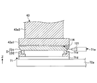
- the processing mechanism 43 has a movable portion 43a on which the grinding tool D is mounted.
- the processing mechanism 43 is a drive mechanism that drives the grinding tool D.
- the grinding tool D is brought into contact with the substrate W to grind the substrate W.
- the grinding tool D includes, for example, a disk-shaped grinding wheel D1 and a plurality of grindstones D2 arranged in a ring shape on the lower surface of the grinding wheel D1.
- the movable portion 43a includes a flange 43a1 on which the grinding tool D is mounted, a spindle shaft 43a2 in which the flange 43a1 is provided at the lower end, and a spindle motor 43a3 for rotating the spindle shaft 43a2.
- the flange 43a1 is arranged horizontally, and the grinding tool D is replaceably attached to the lower surface of the flange 43a1 with a fastener E such as a bolt.
- a plurality of fasteners E are provided at intervals along the peripheral edge of the flange 43a1.
- the spindle shaft 43a2 is arranged vertically.
- the spindle motor 43a3 rotates the spindle shaft 43a2 and rotates the grinding tool D mounted on the flange 43a1.
- the rotation center line R3 of the grinding tool D is the rotation center line of the spindle shaft 43a2.
- the processing mechanism 43 further has an elevating portion 43b for elevating and lowering the movable portion 43a.
- the elevating portion 43b includes, for example, a vertical Z-axis guide 43b1, a Z-axis slider 43b2 that moves along the Z-axis guide 43b1, and a Z-axis motor 43b3 that moves the Z-axis slider 43b2.
- a movable portion 43a is fixed to the Z-axis slider 43b2, and the movable portion 43a and the grinding tool D move up and down together with the Z-axis slider 43b2.
- the elevating part 43b further includes a position detector 43b4 that detects the position of the grinding tool D.
- the position detector 43b4 detects, for example, the rotation of the Z-axis motor 43b3 and detects the position of the grinding tool D.
- the elevating part 43b lowers the grinding tool D from the standby position.
- the grinding tool D rotates while descending, comes into contact with the upper surface of the rotating substrate W, and grinds the entire upper surface of the substrate W.
- the elevating portion 43b stops the lowering of the grinding tool D. After that, the elevating part 43b raises the grinding tool D to the standby position.
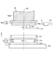
- the grinding device 40 includes an exterior cover 44.
- the exterior cover 44 accommodates a chuck 42 as a holding portion for holding the substrate W and a processing mechanism 43 to which the grinding tool D is replaceably attached.
- the exterior cover 44 suppresses the outflow of particles such as grinding debris generated inside the outer cover 44 to the outside. You can keep the factory room clean.
- the exterior cover 44 has an entrance 44a through which the replacement device 7 passes when entering the inside from the outside of the exterior cover 44. Instead of a human being, the switching device 7 enters the inside from the outside of the exterior cover 44 and replaces the grinding tool D inside the exterior cover 44.
- the changing device 7 enters the inside of the exterior cover 44 instead of the human and replaces the grinding tool D, it is possible to prevent the human from being contaminated by the deposits inside the exterior cover 44. Further, since the switching device 7 is provided outside the grinding device 40, the grinding device 40 can be downsized as compared with the case where the switching device 7 is provided inside the grinding device 40.
- the grinding device 40 includes a shutter 45 that opens and closes the entrance 44a of the exterior cover 44.
- the shutter 45 basically closes the entrance 44a, and opens the entrance 44a when the switching device 7 enters. Compared with the case where the entrance 44a is always open, the outflow of particles from the inside to the outside of the exterior cover 44 through the entrance 44a can be suppressed, and the factory room can be kept clean.
- the grinding device 40 may include a moving mechanism 46 that moves the shutter 45 between an open position that opens the entrance 44a (for example, a position shown in FIG. 5) and a closed position that closes the entrance 44a.
- the moving mechanism 46 is a pneumatic cylinder, an electric cylinder, or the like.
- the electric cylinder includes a motor and a ball screw.
- the shutter 45 can be moved automatically instead of manually.
- the grinding device 40 is provided with a plurality of processing mechanisms 43, and an entrance 44a is provided for each processing mechanism 43.
- the processing mechanism 43 and the entrance 44a are provided at the primary grinding position A1, the secondary grinding position A2, and the tertiary grinding position A3, respectively.
- a shutter 45 is provided at each entrance 44a, and the shutter 45 is moved at each entrance 44a.
- the switching device 7 is provided inside the grinding device 40 for each processing mechanism 43, or when the switching device 7 common to the plurality of processing mechanisms 43 is provided inside the grinding device 40, the grinding device 40 Will become large.
- the replacement device 7 is provided outside the grinding device 40, the grinding device 40 can be miniaturized.
- the number of processing mechanisms 43 may be one.
- the grinding device 40 may include a limiting mechanism 47.
- the limiting mechanism 47 limits the outflow of gas from the inside to the outside of the exterior cover 44 through the entrance 44a of the exterior cover 44. By limiting the outflow of gas, the outflow of particles can be suppressed and the factory room can be kept clean.
- the limiting mechanism 47 includes an exhaust line 47a that makes the inside of the exterior cover 44 negative pressure as compared with the outside.
- the exhaust line 47a is a duct or the like, and connects the exterior cover 44 and the exhaust source.
- the exhaust source is, for example, a vacuum pump or an ejector.
- a barometric pressure controller 47b is provided in the middle of the exhaust line 47a.
- the air pressure controller 47b controls the air pressure inside the exterior cover 44. Due to the difference in air pressure, an air flow from the entrance 44a of the exterior cover 44 toward the inside is formed. As a result, the outflow of gas from the inside to the outside of the exterior cover 44 can be restricted.
- connection port of the exhaust line 47a with the exterior cover 44 is above the entrance 44a of the exterior cover 44 in FIG. 5, but may be below. In the latter case, a downflow can be formed inside the exterior cover 44.
- a blower such as a fan filter unit may be provided on the ceiling of the exterior cover 44. The amount of air blown and the amount of exhaust air are controlled so that the inside of the exterior cover 44 has a negative pressure as compared with the outside.
- the grinding device 40 may include a cleaning mechanism 48.
- the cleaning mechanism 48 supplies the cleaning liquid to the grinding tool D or the peripheral members of the grinding tool D by means of a nozzle or the like.
- the cleaning liquid is, for example, DIW (deionized water) or the like.
- the peripheral member of the grinding tool D is, for example, a flange 43a1 or a spindle shaft 43a2.
- the grinding tool D and the like are cleaned. As a result, it is possible to prevent the switching device 7 from becoming dirty. Further, if the grinding tool D is cleaned by the cleaning mechanism 48, it is possible to suppress the particles from being carried to the outside together with the grinding tool D.
- the grinding device 40 includes a control unit 50.
- the control unit 50 is, for example, a computer, and includes a CPU 50a and a storage medium 50b such as a memory.
- the storage medium 50b stores programs that control various processes executed by the grinding apparatus 40.
- the control unit 50 controls the operation of the grinding apparatus 40 by causing the CPU 50a to execute the program stored in the storage medium 50b.
- the control unit 50 of the grinding device 40 may be a part of the control unit 5 of the grinding system 1.
- the exchange device 7 includes, for example, an exchange mechanism 71, a moving mechanism 72, a traveling table 73, and a traveling mechanism 74.
- the replacement mechanism 71 attaches the grinding tool D to the machining mechanism 43, or removes the grinding tool D from the machining mechanism 43.
- the exchange mechanism 71 can move in the horizontal direction (both directions in the X-axis direction and the Y-axis direction) and in the vertical direction, and can rotate about the vertical axis.
- the moving mechanism 72 moves the replacement mechanism 71 from the outside to the inside of the exterior cover 44 via the entrance 44a of the exterior cover 44.
- the moving mechanism 72 is, for example, an articulated arm, which holds the replacement mechanism 71 at one end and is connected to the traveling table 73 at the other end.
- the traveling table 73 supports the moving mechanism 72.
- the traveling mechanism 74 travels the traveling table 73.
- the exchange device 7 Since the exchange device 7 is provided outside the grinding device 40, a self-propelled robot is used as the exchange device 7, unlike the case where the exchange device 7 is provided inside the grinding device 40. Instead of a human, the switching device 7 replaces the grinding tool D. It can prevent humans from getting dirty. Further, since the switching device 7 is provided outside the grinding device 40, the grinding device 40 can be downsized as compared with the case where the switching device 7 is provided inside the grinding device 40.
- the replacement mechanism 71 has a holding mechanism 71a for holding the grinding tool D.
- the holding mechanism 71a holds the container F that houses the grinding tool D.
- the container F has a box shape that is open upward and has a recess on the upper surface.
- the grinding tool D is housed in the recess.
- the container F accommodates the grinding tool D and prevents the grinding fluid, grinding debris, or the like from falling when the grinding tool D is removed.
- the holding mechanism 71a may hold the grinding tool D.
- the replacement mechanism 71 has a detent mechanism 71b that stops the rotation of the spindle shaft 43a2 of the processing mechanism 43.
- the detent mechanism 71b includes, for example, a clamp that grips the flange 43a1 or the spindle shaft 43a2.
- the detent mechanism 71b includes a pin that is inserted into a hole in the flange 43a1 or the spindle shaft 43a2. The rotation of the spindle shaft 43a2 is stopped by the detent mechanism 71b, and the fastener E can be tightened or loosened in a state where the rotation of the grinding tool D is stopped.
- the replacement mechanism 71 has an operation mechanism 71c that tightens or loosens the fastener E that fastens the grinding tool D and the processing mechanism 43.
- the operating mechanism 71c is composed of a tool such as a spanner or a wrench that fits the bolt and a rotating mechanism that rotates the tool.
- a plurality of sets of the exchange mechanism 71 and the movement mechanism 72 may be provided and controlled independently. One set is used for mounting the grinding tool D and another set is used for removing the grinding tool D. If there are a plurality of sets of the changing mechanism 71 and the moving mechanism 72, the grinding tool D can be quickly removed and attached one after another, unlike the case where there is only one. That is, the replacement device 7 does not have to reciprocate between the grinding device 40 and the storage unit 9 between the removal and installation of the grinding tool D.
- the storage unit 9 (see FIG. 11) of the switching device 7 stores both the used grinding tool D and the unused grinding tool D, even if the replacement mechanism 71 and the moving mechanism 72 are one by one. , The grinding tool D can be quickly removed and attached one after another. Further, if the storage unit 9 (see FIG. 11) of the switching device 7 stores both the used grinding tool D and the unused grinding tool D, the storage unit 9 (see FIG. 11) is fixed to the outside of the switching device 7. It is possible to continuously replace the plurality of processing mechanisms 43 without reciprocating between the grinding device 40 (see FIGS. 1 and 2).
- the exchange device 7 may include an image pickup device 75 that images the exchange mechanism 71.
- the image pickup device 75 is attached to one end of the moving mechanism 72, similarly to the exchange mechanism 71.
- the switching mechanism 71 can be controlled while monitoring the operation of the switching mechanism 71 by the image pickup apparatus 75.
- the switching device 7 includes a control unit 76.
- the control unit 76 is, for example, a computer, and includes a CPU 76a and a storage medium 76b such as a memory.
- the storage medium 76b stores programs that control various processes executed in the switching device 7.
- the control unit 76 controls the operation of the switching device 7 by causing the CPU 76a to execute the program stored in the storage medium 76b.
- each functional block shown in FIG. 7 is conceptual and does not necessarily have to be physically configured as shown in the figure. All or part of each functional block can be functionally or physically distributed / integrated in any unit. Each processing function performed in each function block may be realized by a program executed by a CPU, or as hardware by wired logic, in whole or in an arbitrary part thereof.
- the control unit 50 includes, for example, a replacement command creation unit 50c, a position detection unit 50d, an open / close control unit 50e, a negative pressure control unit 50f, a cleaning control unit 50g, and an auto setup control unit 50h.
- the replacement command creation unit 50c determines whether or not the grinding tool D needs to be replaced, and creates a replacement command for the grinding tool D. Specifically, the replacement command creation unit 50c monitors, for example, the number of substrates W ground by the grinding tool D, the amount of wear of the grinding tool D, the elapsed time from the time when the grinding tool D is attached, and the like. When the value to be set reaches the set value, a replacement command is created.
- the created exchange command is transmitted wirelessly or by wire to the control unit 76 of the exchange device 7.
- the switching device 7 and the grinding device 40 may transmit and receive signals via an external computer. When the switching device 7 receives the replacement command and receives a request from the grinding device 40, the switching device 7 travels to the grinding device 40.
- the position detection unit 50d detects whether or not the traveling table 73 of the switching device 7 has arrived at the position where the grinding tool D is to be replaced (for example, the position shown in FIG. 5) by the detection unit 53.
- the position for replacing the grinding tool D is set outside the exterior cover 44, and serves both as a position for attaching the grinding tool D and a position for removing the grinding tool D.
- the detection unit 53 detects, for example, that the traveling table 73 of the switching device 7 has arrived at a set position outside the exterior cover 44.
- the detection unit 53 is attached to, for example, the outer wall surface of the exterior cover 44, and is attached above the entrance 44a.
- the detection unit 53 is, for example, a camera or the like.
- the open / close control unit 50e controls the movement mechanism 46 of the shutter 45 and controls the position of the shutter 45.
- the open / close control unit 50e changes the position of the shutter 45 from the closed position to the open position. Further, when the traveling table 73 of the switching device 7 exits from the position where the grinding tool D is replaced, the open / close control unit 50e changes the position of the shutter 45 from the open position to the closed position.
- the negative pressure control unit 50f controls the atmospheric pressure controller 47b of the exhaust line 47a to make the inside of the exterior cover 44 negative pressure as compared with the outside.
- the negative pressure control unit 50f makes the inside of the exterior cover 44 negative pressure as compared with the outside, at least while the shutter 45 opens the entrance 44a of the exterior cover 44.
- the cleaning control unit 50g controls the cleaning mechanism 48 and supplies the cleaning liquid to the grinding tool D or the peripheral members of the grinding tool D before the shutter 45 opens the entrance 44a of the exterior cover 44.
- the cleaning liquid is supplied, for example, after the replacement command for the grinding tool D is created.
- the cleaning liquid may be supplied even during grinding of the substrate W or at the end of grinding.
- the auto setup control unit 50h performs auto setup when the replacement of the grinding tool D is completed and the switching device 7 exits from the position where the grinding tool D is replaced.
- the auto setup includes, for example, dressing of an unused grinding tool D or temperature control inside the exterior cover 44.
- the control unit 76 includes, for example, a travel control unit 76c, a movement control unit 76d, and an exchange control unit 76e.
- the travel control unit 76c controls the travel mechanism 74 and controls the position of the travel table 73.
- the traveling control unit 76c controls the traveling mechanism 74 and causes the traveling table 73 to travel between the position where the grinding tool D is stored and the position where the grinding tool D is replaced.
- the movement control unit 76d controls the movement mechanism 72 and controls the position of the exchange mechanism 71.
- the traveling table 73 stops at the position where the grinding tool D is replaced and the switching device 7 detects that the entrance 44a of the exterior cover 44 is open by a signal or the like transmitted from the grinding device 40
- the movement control unit 76d Moves the replacement mechanism 71 from the outside to the inside of the exterior cover 44 via the entrance 44a of the exterior cover 44. Further, before the traveling table 73 exits from the position where the grinding tool D is replaced, the movement control unit 76d moves the replacement mechanism 71 from the inside to the outside of the exterior cover 44 via the entrance 44a of the exterior cover 44.
- the replacement control unit 76e controls the replacement mechanism 71 to control the removal or installation of the grinding tool D.
- the replacement control unit 76e holds the grinding tool D by the holding mechanism 71a, and tightens or loosens the fastener E by the operating mechanism 71c while the rotation of the spindle shaft 43a2 is stopped by the detent mechanism 71b.
- the exchange control unit 76e controls the exchange mechanism 71 while monitoring the operation of the exchange mechanism 71 by the image pickup device 75.
- the grinding device 40 determines whether or not the grinding tool D needs to be replaced, and creates a replacement command for the grinding tool D.
- the grinding device 40 transmits the created exchange command to the exchange device 7. Further, when the grinding device 40 determines that the grinding tool D needs to be replaced, it stops grinding the substrate W and performs cleaning by the cleaning mechanism 48.
- the switching device 7 receives the replacement command from the grinding device 40, the switching device 7 approaches the grinding device 40.
- the grinding device 40 detects that the traveling table 73 of the switching device 7 has reached the position where the grinding tool D is to be replaced, the grinding device 40 opens the shutter 45.
- the exchange device 7 causes the exchange mechanism 71 to enter the inside through the entrance 44a of the exterior cover 44.
- the switching device 7 removes the used grinding tool D from the machining mechanism 43 and attaches the unused grinding tool D to the machining mechanism 43.
- the exchange device 7 causes the exchange mechanism 71 to exit from the entrance 44a of the exterior cover 44 to the outside.
- the grinding device 40 closes the shutter 45 and performs auto setup control.
- the grinding device 40 restarts grinding of the substrate W.
- the limiting mechanism 47 of the grinding device 40 of this modified example has a sealing member 47c in addition to the exhaust line 47a.
- the limiting mechanism 47 may have only the sealing member 47c.
- the seal member 47c comes into contact with the articulated arm or the like of the switching device 7 that has entered the entrance 44a of the exterior cover 44, and closes the entrance 44a of the exterior cover 44.
- the sealing member 47c can limit the outflow of gas and suppress the outflow of particles.
- the seal member 47c is attached to the shutter 45, for example, and is moved together with the shutter 45.
- a pair of shutters 45 are provided, and a seal member 47c is attached to the surfaces of the pair of shutters 45 facing each other.
- the pair of sealing members 47c sandwich and wrap the switching device 7 to close the entrance 44a of the exterior cover 44.
- the seal member 47c is made of a flexible material such as rubber, and is deformed according to the outer shape of the exchange device 7.
- the open / close control unit 50e changes the position of the shutter 45 from the closed position to the open position.
- the movement control unit 76d moves the replacement mechanism 71 from the outside to the inside of the exterior cover 44 via the entrance 44a of the exterior cover 44.
- the seal member 47c does not come into contact with the switching device 7.
- the open / close control unit 50e changes the position of the shutter 45 from the open position to the seal position (for example, the position shown in FIG. 8).
- the seal position is a position where the seal member 47c comes into contact with the articulated arm or the like of the exchange device 7 and closes the entrance 44a of the exterior cover 44.
- the replacement control unit 76e controls the replacement mechanism 71 to remove or attach the grinding tool D.
- the open / close control unit 50e changes the position of the shutter 45 from the seal position to the open position.
- the movement control unit 76d moves the replacement mechanism 71 from the outside to the inside of the exterior cover 44 via the entrance 44a of the exterior cover 44.
- the traveling control unit 76c controls the traveling mechanism 74 and causes the traveling table 73 to travel from the position where the grinding tool D is replaced to the position where the grinding tool D is stored.
- the exterior cover 44 of the grinding device 40 of the present modification is a sub-housing attached to the outer wall surface of the main housing 44b so as to surround the main housing 44b in which the entrance 44a is formed and the entrance 44a of the main housing 44b. It has a body 44c and.
- the main housing 44b accommodates a chuck 42 as a holding portion for holding the substrate W and a processing mechanism 43 to which the grinding tool D is replaceably attached.
- the sub-housing 44c includes a second entrance 44d through which the switching device 7 passes when entering the inside from the outside of the sub-housing 44c. After arriving at the position where the grinding tool D is to be replaced, the switching device 7 passes through the second entrance 44d and the entrance 44a in this order, enters the inside of the main housing 44b, and enters the inside of the main housing 44b. And replace the grinding tool D.
- the grinding device 40 includes a second shutter 61 that opens and closes the second entrance 44d of the auxiliary housing 44c.
- the second shutter 61 basically closes the second entrance 44d, and opens the second entrance 44d when the switching device 7 enters. Compared with the case where the second entrance 44d is always open, the outflow of particles from the inside to the outside of the exterior cover 44 through the second entrance 44d can be suppressed, and the factory room can be kept clean.
- the grinding device 40 includes a second moving mechanism 62 that moves the second shutter 61 between a second open position that opens the second entrance 44d and a second closed position that closes the second entrance 44d. You may.
- the second moving mechanism 62 is a pneumatic cylinder, an electric cylinder, or the like.
- the second shutter 61 can be moved automatically instead of manually.
- the second entrance 44d is provided for each processing mechanism 43, similarly to the entrance 44a.
- the secondary entrance 44d is provided at the primary grinding position A1, the secondary grinding position A2, and the tertiary grinding position A3, respectively.
- a second shutter 61 is provided for each second entrance 44d, and the second shutter 61 is moved for each second entrance 44d.
- the control unit 50 of the grinding device 40 includes a second open / close control unit (not shown).
- the second opening / closing control unit controls the second moving mechanism 62 and controls the position of the second shutter 61.
- the second open / close control unit changes the position of the second shutter 61 from the second closed position to the second open position.
- the traveling table 73 of the switching device 7 exits from the position where the grinding tool D is replaced, the second open / close control unit changes the position of the second shutter 61 from the second open position to the second closed position.
- the limiting mechanism 47 of the grinding device 40 may have a second seal member 47d.
- the second seal member 47d comes into contact with the articulated arm or the like of the switching device 7 that has entered the second entrance 44d of the sub-housing 44c, and closes the second entrance 44d of the sub-housing 44c.
- the second sealing member 47d can limit the outflow of gas and suppress the outflow of particles.
- the second seal member 47d is attached to, for example, the second shutter 61, and is moved together with the second shutter 61.
- a pair of second shutters 61 are provided, and a second seal member 47d is attached to the surfaces of the pair of second shutters 61 facing each other.
- the pair of second seal members 47d sandwich and wrap the exchange device 7 to close the second entrance 44d of the exterior cover 44.
- the second seal member 47d is made of a flexible material such as rubber, and is deformed according to the outer shape of the switching device 7.
- the second open / close control unit changes the position of the second shutter 61 from the second closed position to the second open position.
- the movement control unit 76d moves the exchange mechanism 71 from the outside to the inside of the sub-housing 44c via the second entrance 44d of the sub-housing 44c.
- the second seal member 47d does not come into contact with the switching device 7.
- the second open / close control unit changes the position of the second shutter 61 from the second open position to the second seal position (for example, the position shown in FIG. 9).
- the second seal position is a position where the second seal member 47d comes into contact with the articulated arm or the like of the switching device 7 and closes the second entrance 44d of the auxiliary housing 44c.
- the open / close control unit 50e changes the position of the shutter 45 from the closed position to the open position.
- the movement control unit 76d moves the exchange mechanism 71 from the outside to the inside of the main housing 44b via the entrance 44a of the main housing 44b.
- the open / close control unit 50e changes the position of the shutter 45 from the open position to the seal position.
- the replacement control unit 76e controls the replacement mechanism 71 to remove or attach the grinding tool D.
- the open / close control unit 50e changes the position of the shutter 45 from the seal position to the open position.
- the movement control unit 76d moves the exchange mechanism 71 from the inside of the main housing 44b to the outside via the entrance 44a of the main housing 44b.
- the open / close control unit 50e changes the position of the shutter 45 from the open position to the closed position.
- the second open / close control unit changes the position of the second shutter 61 from the second seal position to the second open position.
- the movement control unit 76d moves the exchange mechanism 71 from the inside of the sub-housing 44c to the outside via the second entrance 44d of the sub-housing 44c.
- the traveling control unit 76c controls the traveling mechanism 74 and causes the traveling table 73 to travel from the position where the grinding tool D is replaced to the position where the grinding tool D is stored. In this way, by closing at least one of the entrance 44a and the second entrance 44d without opening them at the same time, it is possible to prevent the inside of the main housing 44b from being opened to the outside of the grinding device 40. can.
- the replacement device 7 of this modification includes a housing 77 that is attached to the traveling table 73.
- the housing 77 comes into contact with the outer wall surface of the exterior cover 44 in a state of accommodating the replacement mechanism 71 and the moving mechanism 72, and seals the inside of the housing 77.
- the housing 77 may have a sealing member 77a on a contact surface with the exterior cover 44.
- the housing 77 can limit the outflow of gas, suppress the outflow of particles, and keep the factory room clean.
- the housing 77 comes into contact with the outer wall surface of the sub-housing 44c.
- the second shutter 61 opens the second entrance 44d of the sub-housing 44c and the shutter 45 opens the entrance 44a of the main housing 44b, the inside of the housing 77 and the inside of the main housing 44b communicate with each other. ..
- the processing mechanism 43 includes a mounting portion (for example, a flange 43a1) to which the grinding tool D is replaceably mounted, and a fastener E for fastening the flange 43a1 and the grinding tool D.
- the fastener E is, for example, a bolt.
- the fastener E fastens the flange 43a1 and the grinding tool D from above the flange 43a1.
- the fastener E is inserted into a straight hole penetrating the flange 43a1 in the vertical direction, and is screwed into a screw hole formed on the upper surface of the grinding tool D (specifically, the grinding wheel D1).
- the operation of the fastener E is performed by the operation mechanism 71c. As shown in FIG. 6, the operating mechanism 71c tightens and loosens the fastener E above the flange 43a1.
- a cover or the like covering the spindle shaft 43a2 may be provided in order to protect the spindle shaft 43a2 from the grinding fluid containing grinding debris. If a cover or the like is provided, it becomes difficult for the operating mechanism 71c to enter above the flange 43a1, and it becomes difficult to operate the fastener E.
- the fastener E may fasten the flange 43a1 and the grinding tool D from the side of the flange 43a1.
- the fastener E may fasten the flange 43a1 and the grinding tool D from diagonally below the flange 43a1.
- the operating mechanism 71c does not enter above the flange 43a1, so that the operating mechanism 71c can easily operate the fastener E.
- the flange 43a1 includes, for example, a disk-shaped upper flange 101 and a disk-shaped lower flange 102 having an outer diameter smaller than that of the upper flange 101.
- the grinding tool D includes a ring portion 111 for fitting the lower flange 102, a disk portion 112 for closing the lower portion of the ring portion 111, and a plurality of grindstones 113 arranged along the outer circumference of the disk portion 112. .
- the axial direction of the fastener E may be a direction orthogonal to the rotation center line R3 of the spindle shaft 43a2.
- the fastener E is, for example, inserted into a straight hole penetrating the grinding tool D (specifically, the ring portion 111) in the radial direction, and into a screw hole formed on the outer peripheral surface of the flange 43a1 (specifically, the lower flange 102). Screwed in.
- the axial direction of the fastener E may be a direction that inclines downward as the distance from the rotation center line R3 of the spindle shaft 43a2 increases.
- the fastener E is inserted into, for example, a straight hole that obliquely penetrates the grinding tool D, and is screwed into a screw hole formed on the lower surface of the flange 43a1.
- the replacement mechanism 71 has a holding mechanism 71a for holding the grinding tool D.
- the holding mechanism 71a holds, for example, the grinding tool D from below.
- the holding mechanism 71a is provided at the tip of the articulated arm 72a via, for example, the first rotation mechanism 71d described later.
- the tip of the articulated arm 72a enters below the processing mechanism 43 from the side and is lifted upward. After that, the holding mechanism 71a comes into contact with the grinding tool D and holds the grinding tool D.
- the exchange mechanism 71 may have a first rotation mechanism 71d that rotates the holding mechanism 71a.
- the holding mechanism 71a holds the grinding tool D
- the rotation center line of the holding mechanism 71a and the rotation center line R3 of the spindle shaft 43a2 coincide with each other.
- the first rotating mechanism 71d can rotate the grinding tool D and the flange 43a1 at the same time, and the fastener E can be directed to the operating mechanism 71c. Therefore, the operation of the operation mechanism 71c can be simplified.
- the control unit 76 rotates the holding mechanism 71a by the first rotating mechanism 71d and loosens the fasteners E by the operating mechanism 71c. Is repeated. Before the operating mechanism 71c loosens the fastener E, the rotation of the holding mechanism 71a is stopped so that the fastener E faces the operating mechanism 71c. At this time, the control unit 76 monitors the position of the fastener E using the image pickup device 75 shown in FIG. 6, determines whether or not the position of the fastener E is a desired position, and stops the rotation of the holding mechanism 71a. May be controlled. When all the fasteners E are removed, the fastening between the grinding tool D and the processing mechanism 43 is released.
- the replacement mechanism 71 may have a gas supply mechanism 71e that supplies gas between the grinding tool D and the machining mechanism 43, as shown in FIG. 15, in order to support the separation of the grinding tool D and the machining mechanism 43. ..
- the gas supply mechanism 71e includes a nozzle 121 for discharging gas.
- the nozzle 121 supplies gas to, for example, a gap between the lower surface of the upper flange 101 and the upper surface of the ring portion 111. The wind pressure of the gas makes it easy to peel off the grinding tool D and the processing mechanism 43.
- the grinding tool D may be formed with a hole 114 that guides the gas supplied from the nozzle 121 to the contact surface between the grinding tool D and the processing mechanism 43.
- the hole 114 guides the gas supplied from the nozzle 121 to, for example, a gap between the lower surface of the flange 43a1 and the upper surface of the grinding tool D.
- the hole 114 may be a dedicated hole or may also be used as a hole (for example, a straight hole or a screw hole) for mounting the fastener E.
- the exchange mechanism 71 may have a second rotation mechanism 71f that rotates the spindle shaft 43a2 of the processing mechanism 43.
- the second rotation mechanism 71f includes, for example, a roller 131.
- the rotation center line of the roller 131 is parallel to the rotation center line R3 of the spindle shaft 43a2, and the roller 131 and the flange 43a1 come into contact with each other.
- the roller 131 is rotated, the flange 43a1 is rotated by friction.
- the second rotation mechanism 71f rotates the flange 43a1 before attaching the grinding tool D to the flange 43a1, and directs the hole 105 (for example, a screw hole or a straight hole) for mounting the fastener E of the flange 43a1 in a desired direction.
- the control unit 76 monitors the orientation of the flange 43a1 using the image pickup device 75 shown in FIG. 6, determines whether or not the orientation of the flange 43a1 is a desired orientation, and controls the rotation stop position of the flange 43a1. You may.
- the first rotation mechanism 71d rotates the grinding tool D before attaching the grinding tool D to the flange 43a1, and the hole 115 (for example, a straight hole, etc.) for mounting the fastener E of the grinding tool D. Or the screw hole) is oriented in the desired direction.
- the control unit 76 monitors the orientation of the grinding tool D using the image pickup device 75 shown in FIG. 6, determines whether or not the orientation of the grinding tool D is a desired orientation, and determines the rotation stop position of the grinding tool D. May be controlled. After that, the tip of the articulated arm 72a is lifted upward, and the grinding tool D comes into contact with the flange 43a1.
- the orientation of the hole 115 for mounting the fastener E of the grinding tool D and the orientation of the hole 105 for mounting the fastener E of the flange 43a1 are matched.
- the orientation of any one set of holes 115, 105 is directed toward the operating mechanism 71c. After that, the tip of the articulated arm 72a is lifted upward, and the grinding tool D comes into contact with the flange 43a1.
- the operating mechanism 71c fastens the grinding tool D and the flange 43a1 with the fastener E.
- the control unit 76 repeatedly rotates the holding mechanism 71a by the first rotating mechanism 71d and tightens the fastener E by the operating mechanism 71c.
- control unit 76 monitors the positions of the holes 115 and 105 using the image pickup device 75 shown in FIG. 6, determines whether or not the positions of the holes 115 and 105 are desired positions, and rotates the holding mechanism 71a.
- the stop position may be controlled.
- the processing apparatus of the present disclosure is a grinding apparatus in the above embodiment, but may be a cutting apparatus, a cutting apparatus, or the like. Grinding includes polishing.
- the processing device may be provided with a processing mechanism to which the processing tool can be exchangeably attached.
- a cutting tool such as an end mill is replaceably attached to the processing mechanism.
- a cutting tool such as a blade is replaceably attached to the processing mechanism.
- the processing tool may be any one that comes into contact with the processed body and processes the processed body. When the processing tool comes into contact with the processing body and wears, it is replaced.
- processing body processed by the processing apparatus of the present disclosure is the substrate W in the above embodiment, but is not limited to the substrate W.
Abstract
La présente invention concerne un dispositif d'usinage comprenant une unité de maintien qui maintient un objet de traitement, un mécanisme d'usinage auquel une machine-outil permettant d'usiner l'objet de traitement maintenu par l'unité de maintien est fixée de manière interchangeable et un couvercle externe qui reçoit l'unité de maintien et le mécanisme d'usinage. Le couvercle externe a une ouverture d'entrée à travers laquelle passe un dispositif d'échange de la machine-outil lors de son entrée dans le couvercle externe depuis l'extérieur du couvercle externe. Le dispositif d'usinage comprend en outre un obturateur qui ouvre et ferme l'ouverture d'entrée dans le couvercle externe.
Priority Applications (2)
| Application Number | Priority Date | Filing Date | Title |
|---|---|---|---|
| US17/997,557 US20230182253A1 (en) | 2020-05-01 | 2021-04-07 | Processing apparatus, and installing method of processing tool of processing apparatus |
| JP2022517591A JP7467611B2 (ja) | 2020-05-01 | 2021-04-07 | 加工システム |
Applications Claiming Priority (2)
| Application Number | Priority Date | Filing Date | Title |
|---|---|---|---|
| JP2020081378 | 2020-05-01 | ||
| JP2020-081378 | 2020-05-01 |
Publications (1)
| Publication Number | Publication Date |
|---|---|
| WO2021220752A1 true WO2021220752A1 (fr) | 2021-11-04 |
Family
ID=78331522
Family Applications (1)
| Application Number | Title | Priority Date | Filing Date |
|---|---|---|---|
| PCT/JP2021/014826 WO2021220752A1 (fr) | 2020-05-01 | 2021-04-07 | Dispositif d'usinage et procédé de fixation d'une machine-outil à un dispositif d'usinage |
Country Status (3)
| Country | Link |
|---|---|
| US (1) | US20230182253A1 (fr) |
| JP (1) | JP7467611B2 (fr) |
| WO (1) | WO2021220752A1 (fr) |
Citations (10)
| Publication number | Priority date | Publication date | Assignee | Title |
|---|---|---|---|---|
| JPH08257899A (ja) * | 1995-03-24 | 1996-10-08 | Toshiba Mach Co Ltd | 研磨装置 |
| JPH10340872A (ja) * | 1997-06-06 | 1998-12-22 | Ebara Corp | ポリッシング装置 |
| JPH11274271A (ja) * | 1998-03-24 | 1999-10-08 | Dainippon Screen Mfg Co Ltd | 基板処理装置 |
| JP2000052185A (ja) * | 1998-08-10 | 2000-02-22 | Brother Ind Ltd | 工作機械用洗浄装置 |
| JP2008080409A (ja) * | 2006-09-25 | 2008-04-10 | Nippei Toyama Corp | 工作機械の加工ライン |
| JP2009050976A (ja) * | 2007-08-28 | 2009-03-12 | Murata Mach Ltd | ローダ付き工作機械 |
| JP2014205231A (ja) * | 2013-03-21 | 2014-10-30 | ファナック株式会社 | サーボ自動開閉扉を備えた加工システム |
| JP2015093367A (ja) * | 2013-11-14 | 2015-05-18 | トヨタ自動車株式会社 | 加工室の扉開閉制御方法 |
| JP2017094468A (ja) * | 2015-11-26 | 2017-06-01 | ファナック株式会社 | ワークが加工される空間を画定するエンクロージャを備える加工システム |
| WO2020049701A1 (fr) * | 2018-09-06 | 2020-03-12 | ヤマザキマザック株式会社 | Dispositif de stockage d'outil, outil d'usinage et outil d'usinage complexe |
Family Cites Families (3)
| Publication number | Priority date | Publication date | Assignee | Title |
|---|---|---|---|---|
| US7494929B2 (en) * | 2006-04-27 | 2009-02-24 | Applied Materials, Inc. | Automatic gain control |
| US9881820B2 (en) | 2015-10-22 | 2018-01-30 | Lam Research Corporation | Front opening ring pod |
| JP6860416B2 (ja) * | 2017-05-18 | 2021-04-14 | 株式会社ディスコ | 加工装置 |
-
2021
- 2021-04-07 WO PCT/JP2021/014826 patent/WO2021220752A1/fr active Application Filing
- 2021-04-07 US US17/997,557 patent/US20230182253A1/en active Pending
- 2021-04-07 JP JP2022517591A patent/JP7467611B2/ja active Active
Patent Citations (10)
| Publication number | Priority date | Publication date | Assignee | Title |
|---|---|---|---|---|
| JPH08257899A (ja) * | 1995-03-24 | 1996-10-08 | Toshiba Mach Co Ltd | 研磨装置 |
| JPH10340872A (ja) * | 1997-06-06 | 1998-12-22 | Ebara Corp | ポリッシング装置 |
| JPH11274271A (ja) * | 1998-03-24 | 1999-10-08 | Dainippon Screen Mfg Co Ltd | 基板処理装置 |
| JP2000052185A (ja) * | 1998-08-10 | 2000-02-22 | Brother Ind Ltd | 工作機械用洗浄装置 |
| JP2008080409A (ja) * | 2006-09-25 | 2008-04-10 | Nippei Toyama Corp | 工作機械の加工ライン |
| JP2009050976A (ja) * | 2007-08-28 | 2009-03-12 | Murata Mach Ltd | ローダ付き工作機械 |
| JP2014205231A (ja) * | 2013-03-21 | 2014-10-30 | ファナック株式会社 | サーボ自動開閉扉を備えた加工システム |
| JP2015093367A (ja) * | 2013-11-14 | 2015-05-18 | トヨタ自動車株式会社 | 加工室の扉開閉制御方法 |
| JP2017094468A (ja) * | 2015-11-26 | 2017-06-01 | ファナック株式会社 | ワークが加工される空間を画定するエンクロージャを備える加工システム |
| WO2020049701A1 (fr) * | 2018-09-06 | 2020-03-12 | ヤマザキマザック株式会社 | Dispositif de stockage d'outil, outil d'usinage et outil d'usinage complexe |
Also Published As
| Publication number | Publication date |
|---|---|
| JP7467611B2 (ja) | 2024-04-15 |
| US20230182253A1 (en) | 2023-06-15 |
| JPWO2021220752A1 (fr) | 2021-11-04 |
Similar Documents
| Publication | Publication Date | Title |
|---|---|---|
| JP5006053B2 (ja) | 基板処理装置 | |
| CN107887313B (zh) | 加工装置 | |
| JP2024026477A (ja) | 交換装置 | |
| JP2019216207A (ja) | 基板処理方法 | |
| JP2007301690A (ja) | 研磨装置 | |
| JP2015205359A (ja) | 基板処理装置 | |
| WO2021220752A1 (fr) | Dispositif d'usinage et procédé de fixation d'une machine-outil à un dispositif d'usinage | |
| TW201926524A (zh) | 基板搬運裝置、基板處理系統、基板處理方法、程式及電腦記錄媒體 | |
| JP2008098574A (ja) | ウエーハの研磨装置 | |
| WO2017086055A1 (fr) | Appareil de polissage et appareil de traitement de substrat | |
| TW202002143A (zh) | 用於基板搬送系統的教導裝置及教導方法 | |
| TW201937640A (zh) | 基板處理系統、基板處理方法、程式及電腦記錄媒體 | |
| TW202310977A (zh) | 更換裝置及更換方法 | |
| JP5149090B2 (ja) | 加工装置 | |
| JP2023062553A (ja) | 交換装置、処理装置、及び交換方法 | |
| WO2021192837A1 (fr) | Dispositif de traitement d'élimination | |
| JP2021130145A (ja) | 研磨装置および研磨方法 | |
| JP4850666B2 (ja) | ウエーハの加工装置 | |
| JP2002321132A (ja) | ワークの搬送装置 | |
| JP7145283B2 (ja) | バフ処理装置および基板処理装置 | |
| CN220971725U (zh) | 基板处理装置 | |
| JP3239845U (ja) | 基板処理装置 | |
| JP2022180712A (ja) | 研削装置、研削装置の制御方法、及び記憶媒体 | |
| WO2020039802A1 (fr) | Système de traitement de substrat et procédé de traitement de substrat | |
| JP2020031158A (ja) | 基板処理システム |
Legal Events
| Date | Code | Title | Description |
|---|---|---|---|
| 121 | Ep: the epo has been informed by wipo that ep was designated in this application |
Ref document number: 21795388 Country of ref document: EP Kind code of ref document: A1 |
|
| ENP | Entry into the national phase |
Ref document number: 2022517591 Country of ref document: JP Kind code of ref document: A |
|
| NENP | Non-entry into the national phase |
Ref country code: DE |
|
| 122 | Ep: pct application non-entry in european phase |
Ref document number: 21795388 Country of ref document: EP Kind code of ref document: A1 |