WO2021181692A1 - 容器 - Google Patents
容器 Download PDFInfo
- Publication number
- WO2021181692A1 WO2021181692A1 PCT/JP2020/011230 JP2020011230W WO2021181692A1 WO 2021181692 A1 WO2021181692 A1 WO 2021181692A1 JP 2020011230 W JP2020011230 W JP 2020011230W WO 2021181692 A1 WO2021181692 A1 WO 2021181692A1
- Authority
- WO
- WIPO (PCT)
- Prior art keywords
- gusset
- filling
- edge
- container
- main body
- Prior art date
- Legal status (The legal status is an assumption and is not a legal conclusion. Google has not performed a legal analysis and makes no representation as to the accuracy of the status listed.)
- Ceased
Links
Images


Classifications
-
- B—PERFORMING OPERATIONS; TRANSPORTING
- B65—CONVEYING; PACKING; STORING; HANDLING THIN OR FILAMENTARY MATERIAL
- B65D—CONTAINERS FOR STORAGE OR TRANSPORT OF ARTICLES OR MATERIALS, e.g. BAGS, BARRELS, BOTTLES, BOXES, CANS, CARTONS, CRATES, DRUMS, JARS, TANKS, HOPPERS, FORWARDING CONTAINERS; ACCESSORIES, CLOSURES, OR FITTINGS THEREFOR; PACKAGING ELEMENTS; PACKAGES
- B65D75/00—Packages comprising articles or materials partially or wholly enclosed in strips, sheets, blanks, tubes or webs of flexible sheet material, e.g. in folded wrappers
- B65D75/28—Articles or materials wholly enclosed in composite wrappers, i.e. wrappers formed by associating or interconnecting two or more sheets or blanks
- B65D75/30—Articles or materials enclosed between two opposed sheets or blanks having their margins united, e.g. by pressure-sensitive adhesive, crimping, heat-sealing, or welding
- B65D75/32—Articles or materials enclosed between two opposed sheets or blanks having their margins united, e.g. by pressure-sensitive adhesive, crimping, heat-sealing, or welding one or both sheets or blanks being recessed to accommodate contents
- B65D75/321—Both sheets being recessed
- B65D75/322—Both sheets being recessed and forming one compartment
-
- B—PERFORMING OPERATIONS; TRANSPORTING
- B65—CONVEYING; PACKING; STORING; HANDLING THIN OR FILAMENTARY MATERIAL
- B65D—CONTAINERS FOR STORAGE OR TRANSPORT OF ARTICLES OR MATERIALS, e.g. BAGS, BARRELS, BOTTLES, BOXES, CANS, CARTONS, CRATES, DRUMS, JARS, TANKS, HOPPERS, FORWARDING CONTAINERS; ACCESSORIES, CLOSURES, OR FITTINGS THEREFOR; PACKAGING ELEMENTS; PACKAGES
- B65D75/00—Packages comprising articles or materials partially or wholly enclosed in strips, sheets, blanks, tubes or webs of flexible sheet material, e.g. in folded wrappers
- B65D75/008—Standing pouches, i.e. "Standbeutel"
-
- A—HUMAN NECESSITIES
- A47—FURNITURE; DOMESTIC ARTICLES OR APPLIANCES; COFFEE MILLS; SPICE MILLS; SUCTION CLEANERS IN GENERAL
- A47K—SANITARY EQUIPMENT; ACCESSORIES THEREFOR, e.g. TOILET ACCESSORIES
- A47K5/00—Holders or dispensers for soap, toothpaste or the like
- A47K5/06—Dispensers for soap
- A47K5/12—Dispensers for soap for liquid or pasty soap
- A47K5/1202—Dispensers for soap for liquid or pasty soap dispensing dosed volume
- A47K5/1204—Dispensers for soap for liquid or pasty soap dispensing dosed volume by means of a rigid dispensing chamber and pistons
- A47K5/1205—Dispensing from the top of the dispenser with a vertical piston
-
- B—PERFORMING OPERATIONS; TRANSPORTING
- B05—SPRAYING OR ATOMISING IN GENERAL; APPLYING FLUENT MATERIALS TO SURFACES, IN GENERAL
- B05B—SPRAYING APPARATUS; ATOMISING APPARATUS; NOZZLES
- B05B11/00—Single-unit hand-held apparatus in which flow of contents is produced by the muscular force of the operator at the moment of use
- B05B11/01—Single-unit hand-held apparatus in which flow of contents is produced by the muscular force of the operator at the moment of use characterised by the means producing the flow
- B05B11/02—Membranes or pistons acting on the contents inside the container, e.g. follower pistons
- B05B11/026—Membranes separating the content remaining in the container from the atmospheric air to compensate underpressure inside the container
-
- B—PERFORMING OPERATIONS; TRANSPORTING
- B65—CONVEYING; PACKING; STORING; HANDLING THIN OR FILAMENTARY MATERIAL
- B65D—CONTAINERS FOR STORAGE OR TRANSPORT OF ARTICLES OR MATERIALS, e.g. BAGS, BARRELS, BOTTLES, BOXES, CANS, CARTONS, CRATES, DRUMS, JARS, TANKS, HOPPERS, FORWARDING CONTAINERS; ACCESSORIES, CLOSURES, OR FITTINGS THEREFOR; PACKAGING ELEMENTS; PACKAGES
- B65D75/00—Packages comprising articles or materials partially or wholly enclosed in strips, sheets, blanks, tubes or webs of flexible sheet material, e.g. in folded wrappers
- B65D75/52—Details
- B65D75/58—Opening or contents-removing devices added or incorporated during package manufacture
- B65D75/5861—Spouts
- B65D75/5872—Non-integral spouts
- B65D75/5883—Non-integral spouts connected to the package at the sealed junction of two package walls
-
- B—PERFORMING OPERATIONS; TRANSPORTING
- B65—CONVEYING; PACKING; STORING; HANDLING THIN OR FILAMENTARY MATERIAL
- B65D—CONTAINERS FOR STORAGE OR TRANSPORT OF ARTICLES OR MATERIALS, e.g. BAGS, BARRELS, BOTTLES, BOXES, CANS, CARTONS, CRATES, DRUMS, JARS, TANKS, HOPPERS, FORWARDING CONTAINERS; ACCESSORIES, CLOSURES, OR FITTINGS THEREFOR; PACKAGING ELEMENTS; PACKAGES
- B65D77/00—Packages formed by enclosing articles or materials in preformed containers, e.g. boxes, cartons, sacks or bags
- B65D77/04—Articles or materials enclosed in two or more containers disposed one within another
-
- B—PERFORMING OPERATIONS; TRANSPORTING
- B05—SPRAYING OR ATOMISING IN GENERAL; APPLYING FLUENT MATERIALS TO SURFACES, IN GENERAL
- B05B—SPRAYING APPARATUS; ATOMISING APPARATUS; NOZZLES
- B05B11/00—Single-unit hand-held apparatus in which flow of contents is produced by the muscular force of the operator at the moment of use
- B05B11/01—Single-unit hand-held apparatus in which flow of contents is produced by the muscular force of the operator at the moment of use characterised by the means producing the flow
- B05B11/10—Pump arrangements for transferring the contents from the container to a pump chamber by a sucking effect and forcing the contents out through the dispensing nozzle
- B05B11/1042—Components or details
- B05B11/1043—Sealing or attachment arrangements between pump and container
- B05B11/1046—Sealing or attachment arrangements between pump and container the pump chamber being arranged substantially coaxially to the neck of the container
- B05B11/1047—Sealing or attachment arrangements between pump and container the pump chamber being arranged substantially coaxially to the neck of the container the pump being preassembled as an independent unit before being mounted on the container
-
- B—PERFORMING OPERATIONS; TRANSPORTING
- B05—SPRAYING OR ATOMISING IN GENERAL; APPLYING FLUENT MATERIALS TO SURFACES, IN GENERAL
- B05B—SPRAYING APPARATUS; ATOMISING APPARATUS; NOZZLES
- B05B11/00—Single-unit hand-held apparatus in which flow of contents is produced by the muscular force of the operator at the moment of use
- B05B11/01—Single-unit hand-held apparatus in which flow of contents is produced by the muscular force of the operator at the moment of use characterised by the means producing the flow
- B05B11/10—Pump arrangements for transferring the contents from the container to a pump chamber by a sucking effect and forcing the contents out through the dispensing nozzle
- B05B11/1042—Components or details
- B05B11/1059—Means for locking a pump or its actuation means in a fixed position
- B05B11/106—Means for locking a pump or its actuation means in a fixed position in a retracted position, e.g. in an end-of-dispensing-stroke position
Definitions
- the present invention relates to a container.
- Patent Document 1 describes a container having a structure in which a plurality of film layers are laminated and a filler such as air is sealed between the layers to form a filling portion.
- the container of Patent Document 1 has a gusset portion provided with a spout member, and an annular filling portion is formed around a plate portion of the spout member.
- Prior Art Document Patent Document 1 US Patent Application Publication No. 2013/0248540
- the present invention includes a storage area for accommodating the contents and a container body which is composed of a main body constituent sheet material in which a plurality of film layers are laminated and surrounds the storage area.
- the first planar portion, the second planar portion arranged so as to face the first planar portion with the accommodating area in between, and the first planar portion and the second planar portion.
- the gusset portion has a gusset portion that connects the two to each other, and the gusset portion is provided with a discharge port for discharging the contents from the accommodation area, and the main body constituent sheet material is formed of the plurality of film layers.
- the present invention relates to a container including a gusset peripheral peripheral seal piece, and the outer edge of the gusset portion filling portion is defined by the gusset peripheral peripheral seal piece.
- the present invention includes a storage area for accommodating the contents and a container body which is composed of a main body constituent sheet material in which a plurality of film layers are laminated and surrounds the storage area. Is a first planar portion, a second planar portion arranged so as to face the first planar portion with the accommodating area in between, and the first planar portion and the second planar portion.
- the gusset portion has a gusset portion that connects the portions to each other, and the gusset portion is provided with a discharge port for discharging the contents from the accommodation area.
- the filling portion has a filling portion in which a filler can be sealed, and the filling portion includes a gusset portion filling portion arranged in the gusset portion, and the container body includes a peripheral portion of the gusset portion and the first surface thereof.
- the first planar side seal piece including the joint with the peripheral edge of the shaped portion, and the second planar side seal including the joint between the peripheral edge of the gusset and the peripheral edge of the second planar portion.
- a gusseted peripheral seal piece comprising a piece, and a pair of side seal pieces including a joint portion between the peripheral edge portion of the first planar portion and the peripheral edge portion of the second planar portion.
- the gusset filling portion has an inner edge on the side close to the discharge port, and from the inner edge toward the intersection of the first planar side seal piece, the second planar side seal piece, and the side seal piece. Regarding the container extending downward.
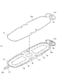
- FIG. 6 (a) is a cross-sectional view taken along the line AA of FIG. 3, and FIG. 6 (b) is a cross-sectional view taken along the line BB of FIG. It is sectional drawing which follows the AA line of FIG.
- the present invention relates to a container having a structure capable of achieving good shape retention of the gusset portion.
- the container 100 includes a storage area 17 for accommodating the contents 18, a container body 20 which is composed of a main body constituent sheet material 21 in which a plurality of film layers are laminated and surrounds the storage area 17. It has.
- the container body 20 includes a first planar portion 20a, a second planar portion 20b arranged so as to face the first planar portion 20a with the accommodating area 17 in between, and a first planar portion 20a. It has a gusset portion (heavenly gusset 14) that connects the second planar portion 20b to each other.
- the gusset portion is provided with a discharge port for discharging the contents 18 from the accommodation area 17.
- the main body constituent sheet material 21 has main body sealing portions 26 and 28 in which a plurality of film layers are bonded to each other, and a non-bonded portion 24 in which the plurality of film layers are partially non-bonded, and is non-bonded.
- the part 24 has a filling part 60 capable of sealing a filler between the layers of the plurality of film layers.
- the filling portion 60 includes a gusset portion filling portion 64 arranged in the gusset portion, and the main body sealing portions 26 and 28 include a gusset portion peripheral edge seal piece 45 arranged along the peripheral edge of the gusset portion. It has been.
- the outer edge of the gusset filling portion 64 is defined by the gusset peripheral peripheral seal piece 45.
- the gusset peripheral peripheral seal piece 45 includes at least an upright piece that stands up toward the outside of the container body 20.
- the gusset peripheral edge seal piece 45 may be composed of only this standing piece, or the standing piece and the main body which is continuous with the standing piece (located inside the standing piece) and is not standing.
- the seal portion 26 and the seal portion 26 may be included.
- the gusset peripheral peripheral seal piece 45 includes an upright piece and a main body seal portion 26 continuous with the upright piece.
- the gusset peripheral edge seal piece 45 may be composed of only standing pieces in the entire area of the gusset peripheral edge seal piece 45, or the gusset peripheral edge seal piece 45 may stand up with the standing piece in the entire area of the gusset peripheral edge seal piece 45. It may be configured to include the main body sealing portion 26 which is not provided, or while the gusset peripheral peripheral seal piece 45 is composed of only standing pieces in a part of the gusset peripheral peripheral seal piece 45 in the extending direction. In other parts of the gusset peripheral peripheral seal piece 45 in the extending direction, the gusset peripheral peripheral seal piece 45 may include a standing piece and a main body seal portion 26 which is not standing.
- the container 100 since the container 100 has the gusset peripheral peripheral seal piece 45 arranged along the peripheral edge of the gusset portion provided with the discharge port, the peripheral edge portion of the gusset portion is the gusset peripheral peripheral seal piece.
- the structure is reinforced by 45.
- the outer edge of the gusset filling portion 64 arranged in the gusset portion is defined by the gusset portion peripheral edge seal piece 45.
- the gusset portion filling portion 64 is formed to have a width reaching the gusset portion peripheral edge seal piece 45, and the gusset portion is reinforced by the gusset portion filling portion 64 over such a width.
- a structure in which the gusset portion is satisfactorily reinforced by the gusset portion peripheral seal piece 45 and the gusset portion filling portion 64 can be realized, and the gusset portion has a good shape retention.
- Sexuality morphological stability
- the pumping operation can be stably performed.
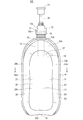
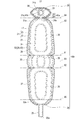
- the container 100 has a bottom gusset 13 (FIGS. 2, 4 and 5) as a bottom portion, and the container 100 can stand on its own in a state where the bottom gusset 13 is placed on a horizontal mounting surface. It has become.
- the description of the positional relationship (upper and lower relationship, etc.) of each component of the container 100 is in a state where the container 100 is self-supporting as shown in FIGS. 1, 2, and 4. It explains the positional relationship. However, the positional relationship in these explanations does not necessarily match the positional relationship when the container 100 is used or manufactured. In addition, the positional relationship shown in each figure may be described with respect to the positional relationship of each component of the container 100.
- the front side of the container 100 (the back side of the paper surface in FIG. 2 and the left side in FIG. 4) is referred to as the front, and the back side of the container 100 (the front side of the paper surface in FIG. 2 and the right side in FIG.
- the left side (the right side in FIG. 2 and the back side of the paper surface in FIG. 4) is referred to as the left side
- the right side (the left side in FIG. 2 and the front side of the paper surface in FIG. 4) facing the front of the container 100 is referred to as the right side.
- the left-right direction of the container 100 may be referred to as a width direction.
- the type of the content 18 is not particularly limited.
- the content 18 include shampoo, conditioner, body soap, detergent, bleach, fabric softener, beverage, food, engine oil, chemicals and the like.
- the content 18 may be a liquid (including a paste), a solid (for example, a granular one (including a granular one), a powdery one, etc.). good.
- the content 18 is, for example, a liquid.
- the viscosity of the content 18 is preferably 1 mPa ⁇ s or more and 120,000 mPa ⁇ s or less (measured with a B-type viscometer.
- Viscometer TV manufactured by Toki Sangyo Co., Ltd.
- a viscometer TVB-10 or the like more preferably 1 mPa ⁇ s or more and 60,000 mPa ⁇ s or less.
- the container body 20 is a bag having a body portion 11, a top gusset 14 arranged on the upper side of the body portion 11, and a bottom gusset 13 arranged on the lower side of the body portion 11. It is formed in a shape.
- the present invention is not limited to this example, and the container body 20 may not have the top gusset 14 and may not have the bottom gusset 13.
- the container body 20 surrounds the storage area 17.
- the container body 20 surrounds the inner bag 40. That is, in the case of the present embodiment, the container 100 includes an inner bag 40 surrounded by the container body 20, and the inner bag 40 has a storage area 17.
- the container body 20 constitutes the outer shell of the container 100.
- the body 11, top gusset 14 and bottom gusset 13 of the container body 20 may be referred to as the body 11, top gusset 14 and bottom gusset 13 of the container 100.
- the front shape of the body portion 11 is not particularly limited, but in the case of the present embodiment, for example, as shown in FIG. 2, the body portion 11 has a vertically long shape having a substantially constant width dimension, and the upper edge of the body portion 11 is upward. It is formed in a convex arc shape. As shown in FIG. 4, the body portion 11 has a first surface-shaped portion 20a (front panel) and a second surface-shaped portion 20b (rear panel) facing each other with the accommodating area 17 in between. Have. The first planar portion 20a is located on the front side, and the second planar portion 20b is located on the back side (see also FIGS. 1 and 2).
- the first planar portion 20a is formed symmetrically, for example, and the second planar portion 20b is also formed symmetrically, for example. Further, the first planar portion 20a and the second planar portion 20b are formed symmetrically in the front-rear direction except for, for example, the connecting portion 65 described later of the filling portion 60.
- the first planar portion 20a bulges convexly toward the front, and the second planar portion 20b bulges convexly toward the rear. However, the first planar portion 20a and the second planar portion 20b may be substantially flat without bulging.
- the container main body 20 is formed by bending the main body constituent sheet material 21 (see FIGS.
- the container body 20 includes a pair of edge portions 29a and 29b extending in parallel with each other from the gusset portion (top gusset 14) side to the opposite side (bottom gusset 13 side).
- the edge portions 29a and 29b are the left and right side edge portions of the container body 20.
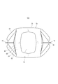
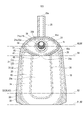
- the planar shape of the heavenly gusset 14 is not particularly limited, but in the case of the present embodiment, as shown in FIG. It is formed in a shape in which the front-rear width decreases from the central part in the direction toward the right.
- the heaven gusset 14 is formed, for example, in a horizontally long tonsil shape.
- the container body 20 extends vertically along the gusset peripheral edge seal piece 45 arranged along the peripheral edge of the gusset 14 and the left and right edge portions 29a and 29b of the body portion 11, respectively, and has a first surface shape.
- a pair of side seal pieces 46 including a joint portion between the peripheral edge portion of the portion 20a and the peripheral edge portion of the second planar portion 20b are provided.
- the gusset peripheral peripheral seal piece 45 and the side seal piece 46 stand, for example, toward the outside of the container body 20.
- gusset peripheral edge seal piece 45 and the side seal piece 46 in the direction orthogonal to the extending direction of the gusset peripheral edge seal piece 45 and the side seal piece 46 (the gusset peripheral edge seal piece 45 and the side seal piece 46) Width dimension) is, for example, substantially constant.
- the gusset peripheral peripheral seal piece 45 surrounds the gusset 14 in a circumferential shape, except for a portion where a connecting portion 65, which will be described later, is present.
- the gusset peripheral edge seal piece 45 is arranged along the boundary between the gusset portion (heavenly gusset 14) and the first surface-shaped portion 20a, and is formed on the peripheral edge portion of the gusset portion (heavenly gusset 14) and the first surface-shaped portion 20a.
- the first surface-shaped portion side seal piece 45a including the joint portion with the peripheral portion is arranged along the boundary between the gusset portion and the second planar portion 20b, and the peripheral portion and the second surface portion of the gusset portion (heavenly gusset 14) are arranged.
- a second surface-shaped portion side seal piece 45b including a joint portion with the peripheral edge portion of the planar portion 20b is included.
- the first surface-shaped portion side seal piece 45a is a main body that joins the outer film layer 22 and the inner film layer 23 along the inner edge of the joint portion between the peripheral edge portion of the gusset portion and the peripheral edge portion of the first planar portion 20a.
- the second surface-shaped portion side seal piece 45b having the sealing portion 26 has an outer film layer 22 and an inner film along the inner edge of the joint portion between the peripheral edge portion of the gusset portion and the peripheral edge portion of the second planar portion 20b. It has a main body seal portion 26 for joining the layer 23 (see FIG. 10). In FIG.
- the main body seal portion 26 constituting the first surface-shaped portion side seal piece 45a and the main body seal portion 26 constituting the second surface-shaped portion side seal piece 45b are designated by reference numerals. It is attached.
- the joint portion between the peripheral edge portion of the gusset portion and the peripheral edge portion of the first planar portion 20a, and the joint portion between the peripheral edge portion of the gusset portion and the peripheral edge portion of the second planar portion 20b are main body seals described later. It is a part of the forming region of the portion 28, and is an upright piece that stands up toward the outside of the container body 20.
- the gusset peripheral peripheral seal piece 45 stands up toward the outside of the container body 20. It includes a standing piece and a main body sealing portion 26 that is continuous with the standing piece (located inside the standing piece).
- the gusset portion filling portion 64 is arranged from the first surface portion side seal piece 45a to the second surface portion side seal piece 45b. That is, the leading edge of the gusset filling portion 64 is defined by the first surface-shaped portion side seal piece 45a, and the trailing edge of the gusset portion filling portion 64 is defined by the second surface-shaped portion side seal piece 45b.
- the outer edge of the gusset filling portion 64 is defined by the gusset peripheral peripheral seal piece 45.
- the outer edge of the gusset filling portion 64 is defined means that 90% or more of the outer edge of the gusset filling portion 64 (90% or more of the total length of the annular outer edge) is the gusset peripheral peripheral seal piece. It means that it is surrounded by 45.
- the outer edge of the gusset portion filling portion 64 is surrounded by the gusset portion peripheral edge seal piece 45 except for the portion where the connecting portion 65 exists.
- the gusset portion filling portion 64 can better reinforce the heaven gusset 14, and the morphological stability of the gusset gusset 14 is further improved. Further, as shown in FIGS. 3, 4 and 6 (a), the gusset filling portion 64 has an inner edge (for example, an annular inner edge) on the side close to the discharge port, and the first from this inner edge. It extends downward toward the intersection 92 of the planar side seal piece 45a, the second planar side seal piece 45b, and the side seal piece 46.
- an inner edge for example, an annular inner edge
- the gusset portion filling portion 64 By having the gusset portion filling portion 64 having a portion extending downward in this way, for example, when the container 100 is a pump container, the pumping operation can be stably performed. Further, when the container 100 is placed in a bathroom or the like, it is possible to prevent water or the like from accumulating in the gusset portion. More specifically, in the gusset portion filling portion 64, portions toward both the left and right sides extend downward from the inner edge of the annular shape toward the intersection 92, respectively. As an example, the shape of the upper edge of the gusset portion filling portion 64 when viewed from the front (or rear view) has a shape curved (bulged) in an arc shape as shown in FIG. 6A, and has a gusset.
- the central position of the portion filling portion 64 extends downward toward the intersection 92. More specifically, in the gusset filling portion 64, the portion located on the right side (toward the right side) of the discharge port has a curved shape that bulges convexly toward the upper right, and is on the left side (toward) of the discharge port. The part located on the left side) has a curved shape that bulges toward the upper left.
- the inner bag 40 is configured by joining a part of the inner bag constituent sheet material 41 (see FIG. 9) to each other at the peripheral edge portion (see FIG. 7). That is, the bag-shaped inner bag 40 is formed by bending the inner bag constituent sheet material 41 and joining the peripheral edges of the inner bag constituent sheet material 41 to each other.
- the inner bag 40 is covered with the container body 20.
- the inner bag 40 has a storage area 17 inside the inner bag 40.
- the inner container is not limited to the inner bag 40 made of the sheet material, for example, blow molding. It may be composed of.
- the shape of the inner bag 40 is not particularly limited, but in the case of the present embodiment, the inner bag 40 is formed in the same shape as the container body 20. As shown in FIG. 7, the inner bag 40 has a first main surface portion 40a located on the front side and a second main surface portion 40b located on the back side with the accommodating area 17 in between.
- the container 100 includes, for example, a spout member 15 provided so as to penetrate the heaven gusset 14, and a cap portion 70 attached to the spout member 15 (for example, detachably attached). That is, the cap portion 70 is attached to a discharge portion having a discharge port (for example, a spout member 15). More specifically, the spout member 15 is, for example, at one end (lower end) of the cylindrical pouring cylinder portion 15a through which the content 18 is passed and the pouring cylinder portion 15a in the axial direction, as shown in FIG. It is integrally provided with a plate-shaped plate portion 15b provided in an arrangement orthogonal to the axial direction.
- a thread is formed on the outer peripheral surface of the dispensing cylinder portion 15a, and the dispensing cylinder portion 15a has a male screw shape.
- the dispensing cylinder portion 15a penetrates the heavenly gusset 14 up and down, and protrudes upward from the heavenly gusset 14.
- the plate portion 15b projects in a flange shape from the lower end of the dispensing cylinder portion 15a toward the periphery.
- the planar shape of the plate portion 15b is not particularly limited, but for example, it may have a substantially square shape (FIG. 3).
- the plate portion 15b is provided on, for example, the inner surface or the outer surface of the portion of the inner bag constituent sheet material 41 that is arranged along the top gusset 14 of the body portion 11.
- the plate portion 15b is joined at the joint portion 91 to the inner surface 152 (lower surface) of the inner bag constituent sheet material 41 in the top gusset 14. .. Therefore, the plate portion 15b is indirectly joined to the main body constituent sheet material 21 via the inner bag constituent sheet material 41.
- the present invention is not limited to this example, and the plate portion 15b may be directly bonded to the inner film layer 23 of the main body constituent sheet material 21.
- the joint portion 91 surrounds the dispensing cylinder portion 15a in a circular manner in a plan view.
- the joint portion 91 defines the inner edge of the gusset portion filling portion 64.
- the formed region of the joint portion 91 is contained inside the outer line of the plate portion 15b in a plan view, for example. More specifically, for example, it is formed in the same range as the annular main body seal portion 26 (see FIG. 10) located around the insertion hole 21a.
- the opening 15c at the tip of the dispensing cylinder portion 15a is a discharge port for discharging the contents 18 from the accommodating area 17.
- An opening 15d is formed in the plate portion 15b coaxially with the inner space of the dispensing cylinder portion 15a. The content 18 in the accommodating area 17 is discharged to the outside through the openings 15d and 15c.
- the container 100 has a plate portion 15b attached to the main body constituent sheet material 21, and the discharge port (opening 15c) discharges the content 18 through the central opening 15d of the plate portion 15b. It has become.
- the outer surface 151 (upper surface) of the plate portion 15b is directly with respect to the innermost layer (inner film layer 23 in the case of the present embodiment) of the main body constituent sheet material 21, or another sheet material (in the case of the present embodiment). It is indirectly joined via the inner bag constituent sheet material 41).
- the main body constituent sheet material 21 is formed from the outer surface 151 of the plate portion 15b. It is arranged so as to bend along the end face of the portion 15b and to face downward from the plate portion 15b. Therefore, the plate portion 15b and thus the spout member 15 are held from the surroundings by the main body constituent sheet material 21 (horizontal movement of the spout member 15 is restricted), so that the stability of the spout member 15 in the horizontal direction is improved.
- the container 100 has a joint portion 91 in which the plate portion 15b is directly or indirectly joined to the main body constituent sheet material 21 via another sheet material, along the outer edge of the joint portion 91.
- the inner edge of the gusset filling portion 64 is arranged.
- the joint portion 91 defines the inner edge of the gusset portion filling portion 64. This also improves the stability of the spout member 15 in the horizontal direction.
- the planar shape of the joint portion 91 is an annular shape. Therefore, the outer edge of the joint portion 91 includes a curved portion that is convex outward. As a result, the tilt of the spout member 15 is suppressed as compared with the case where the outer edge of the joint portion 91 is composed of only straight lines.
- the forming region of the joint portion 91 is contained inside the outer edge of the plate portion 15b. Therefore, as shown in FIGS. 6A and 6B, a part 64b of the gusset filling portion 64 covers the outer surface 151 (upper surface) of the plate portion 15b. As a result, the plate portion 15b is pressed by the gusset portion filling portion 64 from above, so that the plate portion 15b and eventually the spout member 15 are prevented from being displaced upward.
- the other part 64a of the gusset filling portion 64 covers, for example, the inner surface 152 (lower surface) of the plate portion 15b.
- the plate portion 15b is supported by the gusset portion filling portion 64 from below, so that the plate portion 15b and eventually the spout member 15 are prevented from being displaced downward. Therefore, the pumping operation can be performed more stably.
- the cap portion 70 includes, for example, a mounting portion 71 which is a female screw-shaped tubular portion that is detachably screwed to the dispensing cylinder portion 15a, a pump portion 72 fixed to the mounting portion 71, and a pump. It includes a dip tube 77 extending downward from the portion 72, and a head portion 73 held by the pump portion 72 so as to be able to move up and down with respect to the pump portion 72.
- the head portion 73 has, for example, a support cylinder portion 74 projecting upward from the pump portion 72 and a nozzle portion 75 projecting horizontally from the upper end portion of the head portion 73, and is provided at the tip of the nozzle portion 75. Is formed with a discharge port 76 for discharging the contents 18.
- a flow path (not shown) of the content 18 in the cap portion 70 is arranged so as to vertically penetrate the opening 15d and the opening 15c.
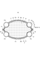
- the filling portion 60 has a first filling portion 61 formed in a circumferential shape along the peripheral edge portion of the first planar portion 20a and a first filling portion 61.
- a second filling portion 62 formed in a circumferential shape along the peripheral edge portion of the two-sided portion 20b, and a third filling portion 63 formed in a circular shape along the peripheral edge portion of the bottom gusset 13 (FIG. 5).
- the gusset portion filling portion 64 formed in a circumferential shape around the pouring cylinder portion 15a in the heaven gusset 14.
- the lower edge of the first filling portion 61 is connected to the leading edge of the third filling portion 63, and the lower edge of the second filling portion 62 is connected to the trailing edge of the third filling portion 63.
- the central portion of the upper end portion in the lateral width direction is connected to the central portion of the front end portion of the gusset portion filling portion 64 in the lateral width direction.
- the first filling portion 61 includes, for example, a first edge filling portion 61a extending vertically along the edge portion 29a and a first filling portion 61 extending vertically along the edge portion 29b.
- It is configured to include a first lower edge filling portion 61d that connects the lower ends of the filling portion 61b to each other.
- the first adjacent filling portion 61c is arranged at the upper end portion of the first planar portion 20a, and extends upward, for example, in a convex arc shape.
- the first lower edge filling portion 61d is arranged at the lower end portion of the first planar portion 20a, and extends substantially horizontally to the left and right, for example.
- the second filling portion 62 includes, for example, a second edge filling portion 62a extending vertically along the edge portion 29a and a second edge filling portion 62 extending vertically along the edge portion 29b.
- the second adjacent filling portion 62c that connects the portion 62b, the upper end of the second edge filling portion 62a and the upper end of the second edge filling portion 62b to each other, and the lower end and the second edge filling portion of the second edge filling portion 62a. It is configured to include a second lower edge filling portion 62d that connects the lower ends of 62b to each other.
- the second adjacent filling portion 62c is arranged at the upper end portion of the second planar portion 20b, and extends upward, for example, in a convex arc shape.
- the second lower edge filling portion 62d is arranged at the lower end portion of the second planar portion 20b, and extends substantially horizontally to the left and right, for example.
- the first adjacent filling portion 61c connects the upper ends of the pair of first edge filling portions 61a and 61b
- the second adjacent filling portion 62c connects the upper ends of the pair of second edge filling portions 62a and 62b. I'm connected.
- the upper end 611 of the first edge filling portion 61b is arranged in the vicinity of a part of the gusset filling portion 64.
- the distance between the upper end 611 of the first edge filling portion 61b and the gusset filling portion 64 is smaller than the thickness D1 of the first edge filling portion 61b at the upper end 611.
- the height position of the upper end 611 of the first edge filling portion 61b is the same as the height position of the intersection 92 between the gusset peripheral peripheral seal piece 45 and the upper end of the side seal piece 46.
- the upper end 621 of the second edge filling portion 62b is arranged in the vicinity of the other part of the gusset filling portion 64.
- the distance between the upper end 621 of the second edge filling portion 62b and the gusset filling portion 64 is smaller than the thickness D2 of the first edge filling portion 61b at the upper end 621.
- the height position of the upper end 621 of the second edge filling portion 62b is the same as the height position of the intersection 92 between the gusset peripheral peripheral seal piece 45 and the upper end of the side seal piece 46.
- each of the upper end of the first edge filling portion 61a and the upper end of the second edge filling portion 62a are arranged in the vicinity of a further part of the gusset filling portion 64 and press each other with the gusset filling portion 64. ing.
- the container body 20 includes a pair of edge portions 29a and 29b extending in parallel with each other from the gusset portion (top gusset 14) side to the opposite side (bottom gusset 13 side), and the filling portion.
- the filling portion In 60, along each of the pair of first edge filling portions 61a and 61b and the pair of edge portions 29a and 29b formed in the first planar portion 20a along each of the pair of edge portions 29a and 29b.
- a pair of second edge filling portions 62a and 62b formed on the second planar portion 20b are included.
- a part of the gusset filling portion 64 is arranged in the vicinity of each of the pair of first edge filling portions 61a and 61b and in the vicinity of each of the pair of second edge filling portions 62a and 62b, respectively.
- the gusset filling portion 64 is satisfactorily supported by the first edge filling portions 61a and 61b and the second edge filling portions 62a and 62b, so that the morphological stability of the gusset filling portion 64 is further improved. ..
- the upper end 611 of the first edge filling portion 61b and the gusset filling portion 64 press against each other (with a part of the inner bag 40 sandwiched between them) inside the container body 20.
- the upper end of the first edge filling portion 61a and the gusset filling portion 64 press against each other inside the container body 20.
- the upper end 621 of the second edge filling portion 62b and the gusset filling portion 64 press each other inside the container body 20 (with a part of the inner bag 40 sandwiched between them).
- the upper end of the second edge filling portion 62a and the gusset filling portion 64 press against each other inside the container body 20.
- the gusset portion filling portion 64 is more satisfactorily supported by the first edge filling portions 61a and 61b and the second edge filling portions 62a and 62b, and the morphological stability of the gusset portion filling portion 64 is further improved.
- first adjacent filling portion 61c extends along the first surface-shaped portion side seal piece 45a.
- second adjacent filling portion 62c extends along the second surface-shaped portion side seal piece 45b. That is, in the filling portion 60, the first adjacent filling portion 61c formed in the first planar portion 20a along the first planar portion side seal piece 45a and the second planar portion side seal piece 45b are formed in the filling portion 60. A second adjacent filling portion 62c formed on the second planar portion 20b is included.
- the gusset portion filling portion 64 is satisfactorily supported by the first adjacent filling portion 61c and the second adjacent filling portion 62c, so that the morphological stability of the gusset portion filling portion 64 is further improved.
- the first adjacent filling portion 61c and the gusset filling portion 64 press against each other (with a part of the inner bag 40 sandwiched between them) inside the container main body 20.
- the second adjacent filling portion 62c and the gusset filling portion 64 press against each other (with a part of the inner bag 40 sandwiched between them) inside the container body 20.
- the gusset portion filling portion 64 is more satisfactorily supported by the first adjacent filling portion 61c and the second adjacent filling portion 62c, and the morphological stability of the gusset portion filling portion 64 is further improved.
- the main body constituent sheet material 21 mutually has an outer film layer 22 forming the outer surface side of the container main body 20 and an inner film layer 23 forming the inner surface side of the container main body 20. It is configured by laminating and joining. That is, as an example, in the case of the present embodiment, the main body constituent sheet material 21 is composed of two film layers, an outer film layer 22 and an inner film layer 23. However, the present invention is not limited to this example, and the main body constituent sheet material 21 may have a film layer other than the outer film layer 22 and the inner film layer 23. In the case of the present embodiment, the outer film layer 22 and the inner film layer 23 are formed to have the same shape.
- the present invention is not limited to this example, and the outer film layer 22 and the inner film layer 23 may have different shapes from each other.
- the outer film layer 22 preferably has a larger shape than the inner film layer 23.
- the outer film layer 22 and the inner film layer 23 are formed with insertion holes through which the ejection tube portion 15a of the spout member 15 is inserted.
- the main body constituent sheet material 21 is formed with a non-bonded portion 24 (FIG. 9) in which the outer film layer 22 and the inner film layer 23 are partially non-bonded.
- a non-bonding treatment can be easily formed by applying a non-bonding agent (so-called glue-killing agent) to bring it into a glue-killing state.
- glue-killing agent any agent can be used as long as it can suppress the bonding between the outer film layer 22 and the inner film layer 23.
- the glue-killing agent for example, printing inks, medium inks, glue-killing inks and the like used for each of offset printing, flexographic printing and letter press printing (letterpress printing) can be preferably used. Further, a thermosetting type ink or an ultraviolet curable type ink can be preferably used.
- the area where the non-joining treatment is applied is the non-joining portion 24.
- the filler can be a fluid (gas or liquid), a solid (eg, granules, resin pellets, etc.) or a semi-solid (eg, foam, etc.), and is preferably a gas such as air.
- the filling portion 60 is not necessarily formed on all of the non-joining portions 24, and may be formed on a part of a plurality of non-joining portions 24.
- a hatching that rises to the right is provided for convenience in the region that is joined to each other to form the main body sealing portion 26.
- FIGS. 9 and 10 in the main body constituent sheet material 21, a region in which the outer film layer 22 and the inner film layer 23 are joined to each other in order to define the non-bonded portion 24, that is, a region where the main body seal portion 26 is formed. Has a hatching that rises to the right for convenience. Further, in FIG.
- the seal boundary line 21c which is the boundary line between the seal region of the peripheral portion of the main body constituent sheet material 21 and the other region, is shown by a two-dot chain line.
- the outer film layer 22 and the inner film layer 23 are joined to each other at the time of bag making, and the inner film is formed.
- the layer 23 and the inner bag constituent sheet material 41 are joined to each other.
- heat sealing, ultrasonic sealing, bonding with an adhesive, or the like can be used as a method of joining the outer film layer 22 and the inner film layer 23, as an example.
- each of the outer film layer 22 and the inner film layer 23 has a layer structure including a plurality of resin layers.
- the inner bag constituent sheet material 41 also has a layer structure including a plurality of resin layers.
- the main body constituent sheet material 21 preferably contains any one of a polyethylene-based, polypropylene-based, polyester-based, and polyamide-based resin layers.
- the material of the resin layer constituting the outer film layer 22 and the inner film layer 23 of the main body constituent sheet material 21 is not particularly limited, and is, for example, high-density polyethylene (HDPE), medium-density polyethylene (MDPE), and low-density polyethylene (LDPE).
- HDPE high-density polyethylene
- MDPE medium-density polyethylene
- LDPE low-density polyethylene
- Linear low density polyethylene LLDPE
- ultra low density polyethylene ULDPE
- polyethylene-based materials such as ethylene-vinyl alcohol copolymer (EVOH), or stretched polypropylene (OPP), unstretched polypropylene (CPP), Polypropylene-based materials such as isotactic PP, syndiotactic PP, atactic PP, random PP, block PP, or polyethylene terephthalate (PET), amorphous polyethylene terephthalate (acrystalline PET), polybutylene terephthalate (PBT), Polyethylene-based materials such as polyethylene naphthalate (PEN) and polybutylene naphthalate (PBN), or polyamides such as stretched nylon (ONy), unstretched nylon (CNy), nylon 6, nylon 66, nylon 11, nylon 12, MXD6, etc. It is more preferably one of the based materials, and among these, the polyethylene-based material is particularly preferable.
- the outer film layer 22 has a four-layer structure formed by laminating four resin layers of the first layer, the second layer, the third layer, and the fourth layer in this order.
- the first layer constitutes the outer surface of the container body 20.
- the first layer is made of, for example, polyethylene terephthalate (PET) or stretched nylon (ONy).
- PET polyethylene terephthalate
- the main function of the first layer is to provide the container body 20 with a glossy feeling and printability, and to secure the rigidity of the container body 20.
- the second layer is, for example, a layer of transparent vapor-deposited PET composed of polyethylene terephthalate in which silica and / or alumina is vapor-deposited on the surface of the second layer on the first-layer side.
- the main function of the second layer is to provide the container body 20 with a gas barrier property.
- the third layer is made of, for example, stretched nylon.
- the main function of the third layer is to secure pinhole resistance of the container body 20.
- the fourth layer is made of, for example, linear low density polyethylene (LLDPE).
- LLDPE linear low density polyethylene
- a fifth layer composed of linear low density polyethylene (LLDPE) is used.
- LLDPE linear low density polyethylene
- the structure to be provided can be mentioned.
- the fifth layer is a layer adjacent to the first layer, and constitutes a surface of the inner film layer 23 opposite to the fourth layer.
- the main function of the fifth layer is to secure heat sealability with the outer film layer 22.
- the main function of the fourth layer of the inner film layer 23 is to secure the heat sealability with the inner bag constituent sheet material 41.
- the layer structure of the outer film layer 22 and the inner film layer 23 is not limited to the above example, and the material of each layer constituting the outer film layer 22 and the inner film layer 23 is not limited to the above example.
- the inner bag constituent sheet material 41 constituting the inner bag 40 has a three-layer structure formed by laminating the first layer, the second layer, and the third layer in this order.
- the first layer is made of, for example, linear low-density polyethylene.
- the main function of the first layer is to secure heat-sealing property with the main body constituent sheet material 21 (heat-sealing property with the inner film layer 23).
- the second layer is, for example, a layer of transparent vapor-deposited stretched nylon composed of stretched nylon in which silica and / or alumina is vapor-deposited on the surface of the second layer on the first layer side.
- the main function of the second layer is to secure gas barrier properties and pinhole resistance.
- the third layer is made of, for example, linear low density polyethylene.
- the main function of the third layer is to secure the heat sealability between the inner bag constituent sheet materials 41.
- the layer structure of the inner bag constituent sheet material 41 is not limited to the structure described here.
- the inner bag constituent sheet material 41 is laminated on the main body constituent sheet material 21, and as shown in FIG. 10, the peripheral edge portion of the inner film layer 23 and the peripheral edge portion of the inner bag constituent sheet material 41 are formed. In addition to being bonded to each other, the peripheral edge of the outer film layer 22 and the peripheral edge of the inner film layer 23 are bonded to each other.
- the container constituent sheet material 51 is composed of the main body constituent sheet material 21 and the inner bag constituent sheet material 41.
- the sealing portion of the peripheral edge portion of the container constituent sheet material 51 is referred to as a peripheral edge sealing portion 52.
- the peripheral edge sealing portion 52 is a sealing portion between the peripheral edge portion of the inner film layer 23 and the peripheral edge portion of the inner bag constituent sheet material 41 (hereinafter, inner / outer sealing portion 43), and the peripheral edge portion of the outer film layer 22 and the inner film layer 23. Includes a seal portion with the peripheral edge portion (hereinafter, main body seal portion 28).
- a gusset peripheral peripheral seal piece 45 is formed in a part of the formed region of the main body seal portion 28, and a side seal piece 46 is formed in the other part.
- the main body sealing portion 28 may also function as a sealing portion that defines the outer peripheral side of the non-joining portion 24, and in a region where the main body sealing portion 28 defines the outer peripheral side of the non-joining portion 24.
- the main body sealing portion 26 located inside the standing piece and not standing may not be present.
- a hatching that rises to the left is provided in the forming region of the peripheral seal portion 52.
- the hatching that rises to the left and the hatching that rises to the right overlap.
- heat seal, ultrasonic seal, bonding with an adhesive, or the like can be used as a method for forming the peripheral seal portion 52.
- the main body constituent sheet material 21 is, for example, a first sheet portion 31 which is a portion constituting the first planar portion 20a and a second sheet which is a portion constituting the second planar portion 20b. It has a portion 32, a bottom gusset constituent sheet portion 38 which is a portion constituting the bottom gusset 13, a heavenly gusset constituent sheet portion 39 which is a portion constituting the heavenly gusset 14, and a tubular extending portion 25.
- the extending portion 25 extends outward from, for example, the second sheet portion 32.
- the top gusset constituent sheet portion 39 is formed with an insertion hole 21a into which the ejection cylinder portion 15a of the spout member 15 is inserted.
- the non-joining portion 24 is formed in a shape corresponding to the shape of the filling portion 60 of the container 100.
- the portion 24b serving as the gusset portion filling portion 64 is formed in a circumferential shape surrounding the insertion hole 21a, for example, as shown in FIG. More specifically, for example, the outer edge (outer line) of the portion 24b has a shape that is one size smaller than the outer line of the top gusset constituent sheet portion 39, and the inner edge of the portion 24b is one size smaller than the insertion hole 21a. It is a large circle.
- the inner bag constituent sheet material 41 is formed in the same shape as the portion of the main body constituent sheet material 21 excluding the extending portion 25.
- the seal boundary line 41a of the inner bag constituent sheet material 41 is shown by a two-dot chain line for convenience.
- the seal boundary line 41a is a boundary line between a region where the inner bag constituent sheet material 41 is joined (sealed) with the main body constituent sheet material 21 and another region in the inner bag constituent sheet material 41, and the container constituent sheet material 51.
- This is a boundary line between a region where the inner bag constituent sheet materials 41 are joined to each other when the container 100 is formed using the above, and another region in the inner bag constituent sheet material 41.
- the position of the seal boundary line 41a and the position of the seal boundary line 21c correspond to each other (overlap each other).
- An insertion hole 41b through which the ejection cylinder portion 15a of the spout member 15 is inserted is formed in a portion of the inner bag constituent sheet material 41 that overlaps with the top gusset constituent sheet portion 39.
- the plate portion 15b of the spout member 15 is joined to, for example, the inner surface of the portion of the inner bag constituent sheet material 41 that overlaps with the top gusset constituent sheet portion 39.
- the injection cylinder portion 15a projects toward the outer surface side of the inner bag constituent sheet material 41 through the insertion hole 41b and the top gusset constituent sheet portion 39 through the insertion hole 21a.
- the container constituent sheet material 51 is valley-folded at the fold line 81, the fold line 82, and the fold line 84 shown in FIG. 10, and is mountain-folded at the fold line 83 and the fold line 85, respectively.
- the container constituent sheet members 51 are formed in a double-structured bag shape.
- the valley fold is a folding method that is convex toward the back side in FIG. 10
- the mountain fold is a folding method that is convex toward the front side in FIG. That is, the edges of the inner bag constituent sheet material 41 are joined to each other to form the inner bag sealing portion 42 (see FIG.
- the inner bag 40 is formed by the inner bag constituent sheet material 41 and the inner bag 40 is formed.
- a bag-shaped container body 20 that covers the bag 40 is formed.
- heat sealing, ultrasonic sealing, joining with an adhesive or the like can be used as a method of joining the inner bag constituent sheet materials 41 to each other.
- the main body seal portion 28, the inner bag seal portion 42, and the inner / outer seal portion 43 are arranged at positions corresponding to each other (positions overlapping each other).
- each of the gusset peripheral peripheral seal piece 45 and the side seal piece 46 includes a main body seal portion 28, an inner bag seal portion 42, and an inner / outer seal portion 43.
- the present invention is not limited to this example, and the gusset peripheral peripheral seal piece 45 and the side seal piece 46 may be composed of only the main body seal portion 28.
- the portion of the top gusset constituent sheet portion 39 side of the bending line 85 is the first overlapping portion 31a.
- the first overlapping portion 31a is arranged so as to overlap one half of the top gusset constituent sheet portion 39 in a state before the non-joining portion 24 is filled with the filler.
- the portion located on the side farther from the bottom gusset constituent sheet portion 38 than the bending line 86 is the second overlapping portion 32a.
- the second overlapping portion 32a is arranged so as to overlap the other half portion of the top gusset constituent sheet portion 39 in a state before the non-joining portion 24 is filled with the filler.
- the container constituent sheet material 51 is formed in a double bag shape, and the container 100 is obtained.
- the filler is injected into the non-joining portion 24 from the injection port 25a (FIG. 10) formed in the extending portion 25, and then the filling material is not connected to the proximal end side of the extending portion 25.
- the joint 24 is sealed.
- the filler is sealed in the non-joining portion 24 (filling portion 60).
- the pressure inside the filling portion 60 is not particularly limited, but is preferably higher than the atmospheric pressure, and can be, for example, 10 kPa or more and 500 kPa or less (gauge pressure).
- the filling portion in which the filler can be sealed is located between the outer film layer 22 and the inner film layer 23, and maintains the airtightness when the filler is sealed at a pressure of about 10 kPa or more and 500 kPa or less. A space where it is possible.
- the extending portion 25 is cut off. In this way, the container 100 in which the filler is sealed in the filling portion 60 is obtained.
- the extension portion 25 may remain even in the state of the container 100 in which the filler is sealed.
- the content 18 is filled in the accommodating area 17 through the pouring cylinder portion 15a of the spout member 15, and then the cap portion 70 is attached to the spout member 15 to fill the accommodating area 17 with the content 18 A container 100 in which is sealed is obtained.
- the present invention is not limited to the above-described embodiment, but also includes various modifications, improvements, and the like as long as the object of the present invention is achieved.
- the container 100 does not have to include the inner bag 40.
- the container body 20 constitutes the storage area 17. That is, in the peripheral seal portion 19, the container main body 20 is formed and the accommodating area 17 is formed by joining a part of the inner film layer 23 of the main body constituent sheet material 21 to each other.
- the outer surface 151 of the plate portion 15b is directly joined to the inner film layer 23 of the main body constituent sheet material 21 by the joining portion 91.
- the container 100 may be other than the pump container.
- the container 100 may have a cap (screw cap or the like) that closes the pouring cylinder portion 15a.
- the container 100 may have a bottom gusset 13 and the discharge port may be self-supporting in an upward posture, or the discharge port may be self-supporting in a downward posture (inverted posture). May be good.
- the retention of water or the like on the upper surface of the heavenly gusset 14 can be suppressed, so that the upper surface of the heavenly gusset 14 can be kept clean.
- the stability of the inverted posture of the container 100 can be ensured.
- the various components of the container 100 do not have to be individually independent, and a plurality of components are formed as one member, and one component is formed of a plurality of members. It is permissible that one component is part of another, that part of one component overlaps with some of another component, and so on.
Landscapes
- Engineering & Computer Science (AREA)
- Mechanical Engineering (AREA)
- Chemical & Material Sciences (AREA)
- Composite Materials (AREA)
- Health & Medical Sciences (AREA)
- Public Health (AREA)
- Bag Frames (AREA)
- Packages (AREA)
Priority Applications (6)
| Application Number | Priority Date | Filing Date | Title |
|---|---|---|---|
| PCT/JP2020/011230 WO2021181692A1 (ja) | 2020-03-13 | 2020-03-13 | 容器 |
| US17/905,801 US12246900B2 (en) | 2020-03-13 | 2020-03-13 | Container |
| CN202080098447.0A CN115279664B (zh) | 2020-03-13 | 2020-03-13 | 容器 |
| JP2022505717A JP7350154B2 (ja) | 2020-03-13 | 2020-03-13 | 容器 |
| EP20924406.0A EP4119461A4 (en) | 2020-03-13 | 2020-03-13 | Container |
| TW110108515A TW202200457A (zh) | 2020-03-13 | 2021-03-10 | 容器 |
Applications Claiming Priority (1)
| Application Number | Priority Date | Filing Date | Title |
|---|---|---|---|
| PCT/JP2020/011230 WO2021181692A1 (ja) | 2020-03-13 | 2020-03-13 | 容器 |
Publications (1)
| Publication Number | Publication Date |
|---|---|
| WO2021181692A1 true WO2021181692A1 (ja) | 2021-09-16 |
Family
ID=77672219
Family Applications (1)
| Application Number | Title | Priority Date | Filing Date |
|---|---|---|---|
| PCT/JP2020/011230 Ceased WO2021181692A1 (ja) | 2020-03-13 | 2020-03-13 | 容器 |
Country Status (6)
| Country | Link |
|---|---|
| US (1) | US12246900B2 (https=) |
| EP (1) | EP4119461A4 (https=) |
| JP (1) | JP7350154B2 (https=) |
| CN (1) | CN115279664B (https=) |
| TW (1) | TW202200457A (https=) |
| WO (1) | WO2021181692A1 (https=) |
Cited By (1)
| Publication number | Priority date | Publication date | Assignee | Title |
|---|---|---|---|---|
| US20230114929A1 (en) * | 2020-03-13 | 2023-04-13 | Kao Corporation | Container |
Citations (6)
| Publication number | Priority date | Publication date | Assignee | Title |
|---|---|---|---|---|
| JPH08207939A (ja) * | 1994-11-18 | 1996-08-13 | Hosokawa Yoko:Kk | バッグインボックス用袋体およびバッグインボックス |
| US20130248540A1 (en) | 2010-11-29 | 2013-09-26 | Ian Darby | Container, container blank, and method of manufacture |
| JP2015000726A (ja) * | 2013-06-13 | 2015-01-05 | 凸版印刷株式会社 | 自立性包装袋 |
| JP2016535707A (ja) * | 2013-11-06 | 2016-11-17 | ザ プロクター アンド ギャンブル カンパニー | 可撓性容器及びその作製方法 |
| JP2016216046A (ja) * | 2015-05-14 | 2016-12-22 | 凸版印刷株式会社 | 液体包装体 |
| JP2018144860A (ja) * | 2017-03-07 | 2018-09-20 | 花王株式会社 | シート材容器 |
Family Cites Families (21)
| Publication number | Priority date | Publication date | Assignee | Title |
|---|---|---|---|---|
| ATE125224T1 (de) | 1992-02-28 | 1995-08-15 | Louis Doyen | Biegsamer behälter, verfahren und vorrichtung zu seiner herstellung. |
| TW367297B (en) * | 1994-11-18 | 1999-08-21 | Hosokawa Yoko Kk | Bag for bag-in-box and bag-in-box |
| US5511697A (en) | 1994-12-19 | 1996-04-30 | The Procter & Gamble Company | Reclosable pouch and method of construction |
| JP5124085B2 (ja) | 2005-08-24 | 2013-01-23 | 押尾産業株式会社 | 自立袋及びその製造方法 |
| JP6090908B2 (ja) | 2012-12-20 | 2017-03-08 | 花王株式会社 | 包装袋 |
| CN110382220B (zh) * | 2017-03-07 | 2021-05-18 | 富吉包装股份有限公司 | 软包装材料容器用中间件、容器和容器包装体的制造方法 |
| EP3483086B1 (en) | 2017-03-07 | 2021-07-21 | Kao Corporation | Sheet material container |
| JP6186547B1 (ja) | 2017-03-07 | 2017-08-23 | 花王株式会社 | シート材容器 |
| EP3492403B1 (en) | 2017-03-07 | 2022-07-06 | Kao Corporation | Container |
| JP7208910B2 (ja) * | 2017-09-28 | 2023-01-19 | 藤森工業株式会社 | 自立性包装袋 |
| CN115279664B (zh) * | 2020-03-13 | 2023-09-29 | 花王株式会社 | 容器 |
| WO2021181691A1 (ja) * | 2020-03-13 | 2021-09-16 | 花王株式会社 | シート材容器 |
| WO2021181690A1 (ja) * | 2020-03-13 | 2021-09-16 | 花王株式会社 | 容器 |
| JP7288139B2 (ja) * | 2020-03-13 | 2023-06-06 | 花王株式会社 | シート材容器 |
| US12280559B2 (en) * | 2020-04-23 | 2025-04-22 | Fuji Seal International, Inc. | Method for manufacturing packaging for pouch container, and device for manufacturing packaging for pouch container |
| JP7386126B2 (ja) * | 2020-05-28 | 2023-11-24 | Pacraft株式会社 | 気体封入方法及び気体封入装置 |
| US20240228144A1 (en) * | 2021-04-26 | 2024-07-11 | Kao Corporation | Sheet member container |
| CN117425599A (zh) * | 2021-05-31 | 2024-01-19 | 花王株式会社 | 片材容器 |
| WO2023037686A1 (ja) * | 2021-09-09 | 2023-03-16 | 株式会社フジシール | パウチ |
| WO2023037474A1 (ja) * | 2021-09-09 | 2023-03-16 | 花王株式会社 | シート材容器 |
| JPWO2023105941A1 (https=) * | 2021-12-08 | 2023-06-15 |
-
2020
- 2020-03-13 CN CN202080098447.0A patent/CN115279664B/zh active Active
- 2020-03-13 US US17/905,801 patent/US12246900B2/en active Active
- 2020-03-13 WO PCT/JP2020/011230 patent/WO2021181692A1/ja not_active Ceased
- 2020-03-13 JP JP2022505717A patent/JP7350154B2/ja active Active
- 2020-03-13 EP EP20924406.0A patent/EP4119461A4/en active Pending
-
2021
- 2021-03-10 TW TW110108515A patent/TW202200457A/zh unknown
Patent Citations (6)
| Publication number | Priority date | Publication date | Assignee | Title |
|---|---|---|---|---|
| JPH08207939A (ja) * | 1994-11-18 | 1996-08-13 | Hosokawa Yoko:Kk | バッグインボックス用袋体およびバッグインボックス |
| US20130248540A1 (en) | 2010-11-29 | 2013-09-26 | Ian Darby | Container, container blank, and method of manufacture |
| JP2015000726A (ja) * | 2013-06-13 | 2015-01-05 | 凸版印刷株式会社 | 自立性包装袋 |
| JP2016535707A (ja) * | 2013-11-06 | 2016-11-17 | ザ プロクター アンド ギャンブル カンパニー | 可撓性容器及びその作製方法 |
| JP2016216046A (ja) * | 2015-05-14 | 2016-12-22 | 凸版印刷株式会社 | 液体包装体 |
| JP2018144860A (ja) * | 2017-03-07 | 2018-09-20 | 花王株式会社 | シート材容器 |
Non-Patent Citations (1)
| Title |
|---|
| See also references of EP4119461A4 |
Cited By (2)
| Publication number | Priority date | Publication date | Assignee | Title |
|---|---|---|---|---|
| US20230114929A1 (en) * | 2020-03-13 | 2023-04-13 | Kao Corporation | Container |
| US12246900B2 (en) * | 2020-03-13 | 2025-03-11 | Kao Corporation | Container |
Also Published As
| Publication number | Publication date |
|---|---|
| CN115279664B (zh) | 2023-09-29 |
| EP4119461A1 (en) | 2023-01-18 |
| EP4119461A4 (en) | 2023-12-06 |
| JP7350154B2 (ja) | 2023-09-25 |
| CN115279664A (zh) | 2022-11-01 |
| TW202200457A (zh) | 2022-01-01 |
| JPWO2021181692A1 (https=) | 2021-09-16 |
| US12246900B2 (en) | 2025-03-11 |
| US20230114929A1 (en) | 2023-04-13 |
Similar Documents
| Publication | Publication Date | Title |
|---|---|---|
| JP6879784B2 (ja) | シート材容器 | |
| JP6186547B1 (ja) | シート材容器 | |
| CN109641681B (zh) | 薄片材料容器 | |
| JP6822917B2 (ja) | シート材容器 | |
| JP6803306B2 (ja) | 容器 | |
| JP6817809B2 (ja) | シート材容器 | |
| JP7212493B2 (ja) | 容器用シート | |
| JP2018144885A (ja) | シート材容器 | |
| JP7288139B2 (ja) | シート材容器 | |
| JP7360535B2 (ja) | シート材容器 | |
| JP2021155062A (ja) | 容器 | |
| WO2021181692A1 (ja) | 容器 | |
| JP7365222B2 (ja) | 容器 | |
| WO2021181690A1 (ja) | 容器 | |
| JP7622240B2 (ja) | シート材容器 | |
| WO2021224995A1 (ja) | シート材容器の製造方法 | |
| JP7524049B2 (ja) | シート材容器 | |
| JP2020083426A (ja) | シート材容器 | |
| JP2021176765A (ja) | シート材容器の製造方法 | |
| JP2021172387A (ja) | 容器 | |
| JP2022180794A (ja) | シート材容器 | |
| JP2023039709A (ja) | シート材容器 | |
| JP2021054537A (ja) | シート材容器 |
Legal Events
| Date | Code | Title | Description |
|---|---|---|---|
| 121 | Ep: the epo has been informed by wipo that ep was designated in this application |
Ref document number: 20924406 Country of ref document: EP Kind code of ref document: A1 |
|
| ENP | Entry into the national phase |
Ref document number: 2022505717 Country of ref document: JP Kind code of ref document: A |
|
| WWE | Wipo information: entry into national phase |
Ref document number: 2020924406 Country of ref document: EP |
|
| ENP | Entry into the national phase |
Ref document number: 2020924406 Country of ref document: EP Effective date: 20221013 |
|
| NENP | Non-entry into the national phase |
Ref country code: DE |
|
| WWG | Wipo information: grant in national office |
Ref document number: 17905801 Country of ref document: US |
|
| WWW | Wipo information: withdrawn in national office |
Ref document number: 2020924406 Country of ref document: EP |