WO2021181692A1 - Container - Google Patents

Container Download PDF

Info

Publication number
WO2021181692A1
WO2021181692A1 PCT/JP2020/011230 JP2020011230W WO2021181692A1 WO 2021181692 A1 WO2021181692 A1 WO 2021181692A1 JP 2020011230 W JP2020011230 W JP 2020011230W WO 2021181692 A1 WO2021181692 A1 WO 2021181692A1
Authority
WO
WIPO (PCT)
Prior art keywords
gusset
filling
edge
container
main body
Prior art date
Application number
PCT/JP2020/011230
Other languages
French (fr)
Japanese (ja)
Inventor
真司 渡辺
Original Assignee
花王株式会社
Priority date (The priority date is an assumption and is not a legal conclusion. Google has not performed a legal analysis and makes no representation as to the accuracy of the date listed.)
Filing date
Publication date
Application filed by 花王株式会社 filed Critical 花王株式会社
Priority to CN202080098447.0A priority Critical patent/CN115279664B/en
Priority to US17/905,801 priority patent/US20230114929A1/en
Priority to EP20924406.0A priority patent/EP4119461A4/en
Priority to JP2022505717A priority patent/JP7350154B2/en
Priority to PCT/JP2020/011230 priority patent/WO2021181692A1/en
Priority to TW110108515A priority patent/TW202200457A/en
Publication of WO2021181692A1 publication Critical patent/WO2021181692A1/en

Links

Images

Classifications

    • BPERFORMING OPERATIONS; TRANSPORTING
    • B65CONVEYING; PACKING; STORING; HANDLING THIN OR FILAMENTARY MATERIAL
    • B65DCONTAINERS FOR STORAGE OR TRANSPORT OF ARTICLES OR MATERIALS, e.g. BAGS, BARRELS, BOTTLES, BOXES, CANS, CARTONS, CRATES, DRUMS, JARS, TANKS, HOPPERS, FORWARDING CONTAINERS; ACCESSORIES, CLOSURES, OR FITTINGS THEREFOR; PACKAGING ELEMENTS; PACKAGES
    • B65D75/00Packages comprising articles or materials partially or wholly enclosed in strips, sheets, blanks, tubes, or webs of flexible sheet material, e.g. in folded wrappers
    • B65D75/28Articles or materials wholly enclosed in composite wrappers, i.e. wrappers formed by associating or interconnecting two or more sheets or blanks
    • B65D75/30Articles or materials enclosed between two opposed sheets or blanks having their margins united, e.g. by pressure-sensitive adhesive, crimping, heat-sealing, or welding
    • B65D75/32Articles or materials enclosed between two opposed sheets or blanks having their margins united, e.g. by pressure-sensitive adhesive, crimping, heat-sealing, or welding one or both sheets or blanks being recessed to accommodate contents
    • B65D75/321Both sheets being recessed
    • B65D75/322Both sheets being recessed and forming one compartment
    • BPERFORMING OPERATIONS; TRANSPORTING
    • B65CONVEYING; PACKING; STORING; HANDLING THIN OR FILAMENTARY MATERIAL
    • B65DCONTAINERS FOR STORAGE OR TRANSPORT OF ARTICLES OR MATERIALS, e.g. BAGS, BARRELS, BOTTLES, BOXES, CANS, CARTONS, CRATES, DRUMS, JARS, TANKS, HOPPERS, FORWARDING CONTAINERS; ACCESSORIES, CLOSURES, OR FITTINGS THEREFOR; PACKAGING ELEMENTS; PACKAGES
    • B65D75/00Packages comprising articles or materials partially or wholly enclosed in strips, sheets, blanks, tubes, or webs of flexible sheet material, e.g. in folded wrappers
    • B65D75/008Standing pouches, i.e. "Standbeutel"
    • AHUMAN NECESSITIES
    • A47FURNITURE; DOMESTIC ARTICLES OR APPLIANCES; COFFEE MILLS; SPICE MILLS; SUCTION CLEANERS IN GENERAL
    • A47KSANITARY EQUIPMENT NOT OTHERWISE PROVIDED FOR; TOILET ACCESSORIES
    • A47K5/00Holders or dispensers for soap, toothpaste, or the like
    • A47K5/06Dispensers for soap
    • A47K5/12Dispensers for soap for liquid or pasty soap
    • A47K5/1202Dispensers for soap for liquid or pasty soap dispensing dosed volume
    • A47K5/1204Dispensers for soap for liquid or pasty soap dispensing dosed volume by means of a rigid dispensing chamber and pistons
    • A47K5/1205Dispensing from the top of the dispenser with a vertical piston
    • BPERFORMING OPERATIONS; TRANSPORTING
    • B05SPRAYING OR ATOMISING IN GENERAL; APPLYING FLUENT MATERIALS TO SURFACES, IN GENERAL
    • B05BSPRAYING APPARATUS; ATOMISING APPARATUS; NOZZLES
    • B05B11/00Single-unit hand-held apparatus in which flow of contents is produced by the muscular force of the operator at the moment of use
    • B05B11/01Single-unit hand-held apparatus in which flow of contents is produced by the muscular force of the operator at the moment of use characterised by the means producing the flow
    • B05B11/02Membranes or pistons acting on the contents inside the container, e.g. follower pistons
    • B05B11/026Membranes separating the content remaining in the container from the atmospheric air to compensate underpressure inside the container
    • BPERFORMING OPERATIONS; TRANSPORTING
    • B65CONVEYING; PACKING; STORING; HANDLING THIN OR FILAMENTARY MATERIAL
    • B65DCONTAINERS FOR STORAGE OR TRANSPORT OF ARTICLES OR MATERIALS, e.g. BAGS, BARRELS, BOTTLES, BOXES, CANS, CARTONS, CRATES, DRUMS, JARS, TANKS, HOPPERS, FORWARDING CONTAINERS; ACCESSORIES, CLOSURES, OR FITTINGS THEREFOR; PACKAGING ELEMENTS; PACKAGES
    • B65D75/00Packages comprising articles or materials partially or wholly enclosed in strips, sheets, blanks, tubes, or webs of flexible sheet material, e.g. in folded wrappers
    • B65D75/52Details
    • B65D75/58Opening or contents-removing devices added or incorporated during package manufacture
    • B65D75/5861Spouts
    • B65D75/5872Non-integral spouts
    • B65D75/5883Non-integral spouts connected to the package at the sealed junction of two package walls
    • BPERFORMING OPERATIONS; TRANSPORTING
    • B65CONVEYING; PACKING; STORING; HANDLING THIN OR FILAMENTARY MATERIAL
    • B65DCONTAINERS FOR STORAGE OR TRANSPORT OF ARTICLES OR MATERIALS, e.g. BAGS, BARRELS, BOTTLES, BOXES, CANS, CARTONS, CRATES, DRUMS, JARS, TANKS, HOPPERS, FORWARDING CONTAINERS; ACCESSORIES, CLOSURES, OR FITTINGS THEREFOR; PACKAGING ELEMENTS; PACKAGES
    • B65D77/00Packages formed by enclosing articles or materials in preformed containers, e.g. boxes, cartons, sacks or bags
    • B65D77/04Articles or materials enclosed in two or more containers disposed one within another
    • BPERFORMING OPERATIONS; TRANSPORTING
    • B05SPRAYING OR ATOMISING IN GENERAL; APPLYING FLUENT MATERIALS TO SURFACES, IN GENERAL
    • B05BSPRAYING APPARATUS; ATOMISING APPARATUS; NOZZLES
    • B05B11/00Single-unit hand-held apparatus in which flow of contents is produced by the muscular force of the operator at the moment of use
    • B05B11/01Single-unit hand-held apparatus in which flow of contents is produced by the muscular force of the operator at the moment of use characterised by the means producing the flow
    • B05B11/10Pump arrangements for transferring the contents from the container to a pump chamber by a sucking effect and forcing the contents out through the dispensing nozzle
    • B05B11/1042Components or details
    • B05B11/1043Sealing or attachment arrangements between pump and container
    • B05B11/1046Sealing or attachment arrangements between pump and container the pump chamber being arranged substantially coaxially to the neck of the container
    • B05B11/1047Sealing or attachment arrangements between pump and container the pump chamber being arranged substantially coaxially to the neck of the container the pump being preassembled as an independent unit before being mounted on the container
    • BPERFORMING OPERATIONS; TRANSPORTING
    • B05SPRAYING OR ATOMISING IN GENERAL; APPLYING FLUENT MATERIALS TO SURFACES, IN GENERAL
    • B05BSPRAYING APPARATUS; ATOMISING APPARATUS; NOZZLES
    • B05B11/00Single-unit hand-held apparatus in which flow of contents is produced by the muscular force of the operator at the moment of use
    • B05B11/01Single-unit hand-held apparatus in which flow of contents is produced by the muscular force of the operator at the moment of use characterised by the means producing the flow
    • B05B11/10Pump arrangements for transferring the contents from the container to a pump chamber by a sucking effect and forcing the contents out through the dispensing nozzle
    • B05B11/1042Components or details
    • B05B11/1059Means for locking a pump or its actuation means in a fixed position
    • B05B11/106Means for locking a pump or its actuation means in a fixed position in a retracted position, e.g. in an end-of-dispensing-stroke position

Landscapes

  • Engineering & Computer Science (AREA)
  • Mechanical Engineering (AREA)
  • Chemical & Material Sciences (AREA)
  • Composite Materials (AREA)
  • Health & Medical Sciences (AREA)
  • Public Health (AREA)
  • Bag Frames (AREA)

Abstract

This container (100) is provided with a container main body (20) which is configured from a main body constituting sheet material (21) so as to surround a containing region. The container main body (20) has a first planar part (20a), a second planar part (20b) that is arranged so as to face the first planar part (20a) with the containing region being positioned therebetween, and a gusset part (for example, a top gusset (14)) that connects the first planar part (20a) and the second planar part (20b) to each other; and the gusset part is provided with an ejection port through which the content is ejected from the containing region. The main body constituting sheet material (21) has a main body seal part wherein a plurality of film layers are bonded with each other and a non-bonded part wherein the plurality of film layers are not partially bonded with each other, while being provided with a filling part (60), in which a filler is able to be sealed, between the plurality of film layers in the non-bonded part. The filling part (60) comprises a gusset part filling part (64) that is arranged in the gusset part; the main body seal part comprises a gusset part peripheral edge seal piece (45) that is arranged along the peripheral edge of the gusset part; and the outer edge of the gusset part filling part (64) is defined by the gusset part peripheral edge seal piece (45).

Description

容器container
 本発明は、容器に関する。 The present invention relates to a container.
 複数のフィルム層が積層され、その層間に空気などの充填材が封入されて充填部が形成されている構造の容器は、例えば、特許文献1に記載されている。
 特許文献1の容器は、スパウト部材が設けられた天マチ部を有し、スパウト部材の板部の周囲には、環状の充填部が形成されている。
先行技術文献
 特許文献1 米国特許出願公開第2013/0248540号明細書
For example, Patent Document 1 describes a container having a structure in which a plurality of film layers are laminated and a filler such as air is sealed between the layers to form a filling portion.
The container of Patent Document 1 has a gusset portion provided with a spout member, and an annular filling portion is formed around a plate portion of the spout member.
Prior Art Document Patent Document 1 US Patent Application Publication No. 2013/0248540
 本発明は、内容物を収容する収容領域と、複数のフィルム層を積層した本体構成シート材により構成されており、前記収容領域を包囲している容器本体と、を備え、前記容器本体は、第1面状部と、前記収容領域を間に挟んで前記第1面状部と対向して配置されている第2面状部と、前記第1面状部と前記第2面状部とを相互に繋いでいるマチ部と、を有し、前記マチ部には、前記収容領域から前記内容物を吐出する吐出口が設けられており、前記本体構成シート材は、前記複数のフィルム層どうしが接合された本体シール部と、前記複数のフィルム層どうしが部分的に非接合とされた非接合部と、を有するとともに、前記非接合部における前記複数のフィルム層どうしの層間に充填材を封入可能な充填部を有し、前記充填部には、前記マチ部に配置されているマチ部充填部が含まれ、前記本体シール部には、前記マチ部の周縁に沿って配置されているマチ部周縁シール片が含まれ、前記マチ部周縁シール片によって、前記マチ部充填部の外縁が画定されている容器に関する。 The present invention includes a storage area for accommodating the contents and a container body which is composed of a main body constituent sheet material in which a plurality of film layers are laminated and surrounds the storage area. The first planar portion, the second planar portion arranged so as to face the first planar portion with the accommodating area in between, and the first planar portion and the second planar portion. The gusset portion has a gusset portion that connects the two to each other, and the gusset portion is provided with a discharge port for discharging the contents from the accommodation area, and the main body constituent sheet material is formed of the plurality of film layers. It has a main body seal portion in which the film layers are bonded to each other and a non-bonded portion in which the plurality of film layers are partially non-bonded, and a filler between the layers of the plurality of film layers in the non-bonded portion. The filling portion includes a gusset portion filling portion arranged in the gusset portion, and the main body seal portion is arranged along the peripheral edge of the gusset portion. The present invention relates to a container including a gusset peripheral peripheral seal piece, and the outer edge of the gusset portion filling portion is defined by the gusset peripheral peripheral seal piece.
 また、本発明は、内容物を収容する収容領域と、複数のフィルム層を積層した本体構成シート材により構成されており、前記収容領域を包囲している容器本体と、を備え、前記容器本体は、第1面状部と、前記収容領域を間に挟んで前記第1面状部と対向して配置されている第2面状部と、前記第1面状部と前記第2面状部とを相互に繋いでいるマチ部と、を有し、前記マチ部には、前記収容領域から前記内容物を吐出する吐出口が設けられており、前記本体構成シート材は、前記複数のフィルム層どうしが接合された本体シール部と、前記複数のフィルム層どうしが部分的に非接合とされた非接合部と、を有するとともに、前記非接合部における前記複数のフィルム層どうしの層間に充填材が封入可能な充填部を有し、前記充填部には、前記マチ部に配置されているマチ部充填部が含まれ、前記容器本体は、前記マチ部の周縁部と前記第1面状部の周縁部との接合部を含む第1面状部側シール片と、前記マチ部の周縁部と前記第2面状部の周縁部との接合部を含む第2面状部側シール片と、を備えるマチ部周縁シール片と、前記第1面状部の周縁部と前記第2面状部の周縁部との接合部を含む一対の側部シール片と、を有し、前記マチ部充填部は、前記吐出口に近い側の内縁を有し、前記内縁から前記第1面状部側シール片、第2面状部側シール片および前記側部シール片の交点へ向かって下方に延びている容器に関する。 Further, the present invention includes a storage area for accommodating the contents and a container body which is composed of a main body constituent sheet material in which a plurality of film layers are laminated and surrounds the storage area. Is a first planar portion, a second planar portion arranged so as to face the first planar portion with the accommodating area in between, and the first planar portion and the second planar portion. The gusset portion has a gusset portion that connects the portions to each other, and the gusset portion is provided with a discharge port for discharging the contents from the accommodation area. It has a main body sealing portion in which film layers are bonded to each other and a non-bonded portion in which the plurality of film layers are partially non-bonded, and between the layers of the plurality of film layers in the non-bonded portion. The filling portion has a filling portion in which a filler can be sealed, and the filling portion includes a gusset portion filling portion arranged in the gusset portion, and the container body includes a peripheral portion of the gusset portion and the first surface thereof. The first planar side seal piece including the joint with the peripheral edge of the shaped portion, and the second planar side seal including the joint between the peripheral edge of the gusset and the peripheral edge of the second planar portion. A gusseted peripheral seal piece comprising a piece, and a pair of side seal pieces including a joint portion between the peripheral edge portion of the first planar portion and the peripheral edge portion of the second planar portion. The gusset filling portion has an inner edge on the side close to the discharge port, and from the inner edge toward the intersection of the first planar side seal piece, the second planar side seal piece, and the side seal piece. Regarding the container extending downward.
実施形態に係る容器の充填材を封入した状態の斜視図である。It is a perspective view of the state in which the filler of the container which concerns on embodiment is sealed. 実施形態に係る容器の充填材を封入した状態の背面図である。It is a rear view of the state in which the filler of the container which concerns on embodiment is sealed. 実施形態に係る容器の充填材を封入した状態の平面図であり、キャップ部を外した状態を示す。It is a top view of the state which filled with the filler of the container which concerns on embodiment, and shows the state which the cap part was removed. 実施形態に係る容器の充填材を封入した状態の側面図である。It is a side view of the state in which the filler of the container which concerns on embodiment is sealed. 実施形態に係る容器の充填材を封入した状態の底面図である。It is the bottom view of the state in which the filler of the container which concerns on embodiment is sealed. 図6(a)は図3のA-A線に沿った断面図であり、図6(b)は図3のB-B線に沿った断面図である。6 (a) is a cross-sectional view taken along the line AA of FIG. 3, and FIG. 6 (b) is a cross-sectional view taken along the line BB of FIG. 図2のA-A線に沿った断面図である。It is sectional drawing which follows the AA line of FIG. 本体構成シート材の内側フィルム層と外側フィルム層とを示す分解斜視図である。It is an exploded perspective view which shows the inner film layer and the outer film layer of the main body constitution sheet material. 内袋構成シート材と本体構成シート材とを示す分解斜視図である。It is an exploded perspective view which shows the inner bag constituent sheet material and the main body constituent sheet material. 相互に積層された内袋構成シート材と本体構成シート材とを有する容器構成シート材を示す平面図である。It is a top view which shows the container composition sheet material which has the inner bag composition sheet material and the main body composition sheet material which are laminated with each other. 実施形態に係る容器の充填材を封入する前の状態の平面図である。It is a top view of the state before sealing the filler of the container which concerns on embodiment.
発明の詳細な説明Detailed description of the invention
 本願発明者の検討によれば、特許文献1の容器は、天マチ部の保形性に関してなお改善の余地がある。 According to the examination of the inventor of the present application, there is still room for improvement in the shape retention of the gusset portion of the container of Patent Document 1.
 本発明は、マチ部の良好な保形性を実現することが可能な構造の容器に関する。 The present invention relates to a container having a structure capable of achieving good shape retention of the gusset portion.
 以下、本発明の好ましい実施形態について、図面を用いて説明する。なお、すべての図面において、同様の構成要素には同一の符号を付し、重複する説明は適宜に省略する。 Hereinafter, preferred embodiments of the present invention will be described with reference to the drawings. In all drawings, similar components are designated by the same reference numerals, and duplicate description will be omitted as appropriate.
 本実施形態に係る容器100は、内容物18を収容する収容領域17と、複数のフィルム層を積層した本体構成シート材21により構成されており収容領域17を包囲している容器本体20と、を備えている。容器本体20は、第1面状部20aと、収容領域17を間に挟んで第1面状部20aと対向して配置されている第2面状部20bと、第1面状部20aと第2面状部20bとを相互に繋いでいるマチ部(天マチ14)と、を有する。
 マチ部には、収容領域17から内容物18を吐出する吐出口が設けられている。
 本体構成シート材21は、複数のフィルム層どうしが接合された本体シール部26、28と、複数のフィルム層どうしが部分的に非接合とされた非接合部24と、を有するとともに、非接合部24における複数のフィルム層どうしの層間に充填材を封入可能な充填部60を有する。
 充填部60には、マチ部に配置されているマチ部充填部64が含まれ、本体シール部26、28には、マチ部の周縁に沿って配置されているマチ部周縁シール片45が含まれている。マチ部周縁シール片45によって、マチ部充填部64の外縁が画定されている。
 ここで、マチ部周縁シール片45は、容器本体20の外方に向けて起立している起立片を少なくとも含んでいる。マチ部周縁シール片45は、この起立片のみにより構成されていてもよいし、起立片と、当該起立片に連続していて(起立片よりも内側に位置していて)起立していない本体シール部26と、を含んでいてもよい。本実施形態の場合、マチ部周縁シール片45は、起立片と、当該起立片に連続している本体シール部26と、を含む。また、マチ部周縁シール片45の全域においてマチ部周縁シール片45が起立片のみにより構成されていてもよいし、マチ部周縁シール片45の全域においてマチ部周縁シール片45が起立片と起立していない本体シール部26とを含んで構成されていてもよいし、マチ部周縁シール片45の延在方向における一部分においてはマチ部周縁シール片45が起立片のみにより構成されている一方で、マチ部周縁シール片45の延在方向における他の部分においてはマチ部周縁シール片45が起立片と起立していない本体シール部26とを含んで構成されていてもよい。
The container 100 according to the present embodiment includes a storage area 17 for accommodating the contents 18, a container body 20 which is composed of a main body constituent sheet material 21 in which a plurality of film layers are laminated and surrounds the storage area 17. It has. The container body 20 includes a first planar portion 20a, a second planar portion 20b arranged so as to face the first planar portion 20a with the accommodating area 17 in between, and a first planar portion 20a. It has a gusset portion (heavenly gusset 14) that connects the second planar portion 20b to each other.
The gusset portion is provided with a discharge port for discharging the contents 18 from the accommodation area 17.
The main body constituent sheet material 21 has main body sealing portions 26 and 28 in which a plurality of film layers are bonded to each other, and a non-bonded portion 24 in which the plurality of film layers are partially non-bonded, and is non-bonded. The part 24 has a filling part 60 capable of sealing a filler between the layers of the plurality of film layers.
The filling portion 60 includes a gusset portion filling portion 64 arranged in the gusset portion, and the main body sealing portions 26 and 28 include a gusset portion peripheral edge seal piece 45 arranged along the peripheral edge of the gusset portion. It has been. The outer edge of the gusset filling portion 64 is defined by the gusset peripheral peripheral seal piece 45.
Here, the gusset peripheral peripheral seal piece 45 includes at least an upright piece that stands up toward the outside of the container body 20. The gusset peripheral edge seal piece 45 may be composed of only this standing piece, or the standing piece and the main body which is continuous with the standing piece (located inside the standing piece) and is not standing. The seal portion 26 and the seal portion 26 may be included. In the case of the present embodiment, the gusset peripheral peripheral seal piece 45 includes an upright piece and a main body seal portion 26 continuous with the upright piece. Further, the gusset peripheral edge seal piece 45 may be composed of only standing pieces in the entire area of the gusset peripheral edge seal piece 45, or the gusset peripheral edge seal piece 45 may stand up with the standing piece in the entire area of the gusset peripheral edge seal piece 45. It may be configured to include the main body sealing portion 26 which is not provided, or while the gusset peripheral peripheral seal piece 45 is composed of only standing pieces in a part of the gusset peripheral peripheral seal piece 45 in the extending direction. In other parts of the gusset peripheral peripheral seal piece 45 in the extending direction, the gusset peripheral peripheral seal piece 45 may include a standing piece and a main body seal portion 26 which is not standing.
 本実施形態によれば、容器100は、吐出口が設けられたマチ部の周縁に沿って配置されているマチ部周縁シール片45を有するため、当該マチ部の周縁部がマチ部周縁シール片45により補強された構造となっている。
 しかも、マチ部周縁シール片45によって、マチ部に配置されているマチ部充填部64の外縁が画定されている。換言すれば、マチ部充填部64はマチ部周縁シール片45に達する広さに形成されており、マチ部は、そのような広さに亘って、マチ部充填部64により補強されている。
 よって、マチ部充填部64に充填材が封入された状態では、マチ部がマチ部周縁シール片45及びマチ部充填部64によって良好に補強された構造を実現でき、マチ部の良好な保形性(形態安定性)を実現することができる。これにより、例えば容器100がポンプ容器である場合に、ポンピング操作を安定的に行うことが可能となる。
According to the present embodiment, since the container 100 has the gusset peripheral peripheral seal piece 45 arranged along the peripheral edge of the gusset portion provided with the discharge port, the peripheral edge portion of the gusset portion is the gusset peripheral peripheral seal piece. The structure is reinforced by 45.
Moreover, the outer edge of the gusset filling portion 64 arranged in the gusset portion is defined by the gusset portion peripheral edge seal piece 45. In other words, the gusset portion filling portion 64 is formed to have a width reaching the gusset portion peripheral edge seal piece 45, and the gusset portion is reinforced by the gusset portion filling portion 64 over such a width.
Therefore, in a state where the filler is sealed in the gusset filling portion 64, a structure in which the gusset portion is satisfactorily reinforced by the gusset portion peripheral seal piece 45 and the gusset portion filling portion 64 can be realized, and the gusset portion has a good shape retention. Sexuality (morphological stability) can be realized. Thereby, for example, when the container 100 is a pump container, the pumping operation can be stably performed.
 本実施形態の場合、容器100は、底部としての底マチ13(図2、図4、図5)を有しており、底マチ13が水平な載置面に載置された状態で自立可能となっている。 In the case of the present embodiment, the container 100 has a bottom gusset 13 (FIGS. 2, 4 and 5) as a bottom portion, and the container 100 can stand on its own in a state where the bottom gusset 13 is placed on a horizontal mounting surface. It has become.
 本実施形態において、容器100の各構成要素の位置関係(上下関係等)の説明は、特に断りのない場合は、容器100を図1、図2及び図4のように自立させた状態での位置関係を説明したものである。ただし、これらの説明における位置関係は、容器100の使用時や製造時の位置関係とは必ずしも一致しない。
 また、容器100の各構成要素の位置関係について、各図に示される位置関係を説明する場合もある。
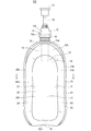
 容器100の正面側(図2における紙面の奥側、図4における左側)を前方、容器100の背面側(図2における紙面の手前側、図4における右側)を後方といい、容器100の正面に向かって左側(図2における右側、図4における紙面の奥側)を左方、容器100の正面に向かって右側(図2における左側、図4における紙面の手前側)を右方という。また、容器100の左右方向を横幅方向という場合がある。
In the present embodiment, unless otherwise specified, the description of the positional relationship (upper and lower relationship, etc.) of each component of the container 100 is in a state where the container 100 is self-supporting as shown in FIGS. 1, 2, and 4. It explains the positional relationship. However, the positional relationship in these explanations does not necessarily match the positional relationship when the container 100 is used or manufactured.
In addition, the positional relationship shown in each figure may be described with respect to the positional relationship of each component of the container 100.
The front side of the container 100 (the back side of the paper surface in FIG. 2 and the left side in FIG. 4) is referred to as the front, and the back side of the container 100 (the front side of the paper surface in FIG. 2 and the right side in FIG. 4) is referred to as the rear. The left side (the right side in FIG. 2 and the back side of the paper surface in FIG. 4) is referred to as the left side, and the right side (the left side in FIG. 2 and the front side of the paper surface in FIG. 4) facing the front of the container 100 is referred to as the right side. Further, the left-right direction of the container 100 may be referred to as a width direction.
 本発明において、内容物18の種類は、特に限定されない。内容物18としては、例えば、シャンプー、リンス、ボディーソープ、洗剤、漂白剤、柔軟剤、飲料、食品の他に、エンジンオイル、化学薬品などが挙げられる。
 また、内容物18は、液体(ペースト状のものを含む)であっても良いし、固体(例えば、粒状のもの(顆粒状のものを含む)、或いは粉状のものなど)であっても良い。
 本実施形態の場合、内容物18は、例えば、液体である。
 内容物18が液体の場合には、内容物18の粘度は、例えば30℃において好ましくは1mPa・s以上12万mPa・s以下(B型粘度計で測定。例えば東機産業社製ビスコメーターTV-10又はビスコメーターTVB-10等で測定)であり、より好ましくは1mPa・s以上6万mPa・s以下である。
In the present invention, the type of the content 18 is not particularly limited. Examples of the content 18 include shampoo, conditioner, body soap, detergent, bleach, fabric softener, beverage, food, engine oil, chemicals and the like.
Further, the content 18 may be a liquid (including a paste), a solid (for example, a granular one (including a granular one), a powdery one, etc.). good.
In the case of this embodiment, the content 18 is, for example, a liquid.
When the content 18 is a liquid, the viscosity of the content 18 is preferably 1 mPa · s or more and 120,000 mPa · s or less (measured with a B-type viscometer. For example, Viscometer TV manufactured by Toki Sangyo Co., Ltd.) at 30 ° C. -10 or measured with a viscometer TVB-10 or the like), more preferably 1 mPa · s or more and 60,000 mPa · s or less.
 本実施形態の場合、容器本体20は、胴部11と、胴部11の上側に配置されている天マチ14と、胴部11の下側に配置されている底マチ13と、を有する袋状に形成されている。ただし、本発明は、この例に限らず、容器本体20は、天マチ14を有していなくてもよく、また、底マチ13を有していなくてもよい。
 容器本体20は、収容領域17を包囲している。本実施形態の場合、容器本体20は、内袋40を包囲している。すなわち、本実施形態の場合、容器100は、容器本体20に包囲されている内袋40を備え、内袋40が収容領域17を有する。
 容器本体20は容器100の外殻を構成している。以下では、容器本体20の胴部11、天マチ14及び底マチ13のことを、容器100の胴部11、天マチ14及び底マチ13と称する場合がある。
In the case of the present embodiment, the container body 20 is a bag having a body portion 11, a top gusset 14 arranged on the upper side of the body portion 11, and a bottom gusset 13 arranged on the lower side of the body portion 11. It is formed in a shape. However, the present invention is not limited to this example, and the container body 20 may not have the top gusset 14 and may not have the bottom gusset 13.
The container body 20 surrounds the storage area 17. In the case of the present embodiment, the container body 20 surrounds the inner bag 40. That is, in the case of the present embodiment, the container 100 includes an inner bag 40 surrounded by the container body 20, and the inner bag 40 has a storage area 17.
The container body 20 constitutes the outer shell of the container 100. In the following, the body 11, top gusset 14 and bottom gusset 13 of the container body 20 may be referred to as the body 11, top gusset 14 and bottom gusset 13 of the container 100.
 胴部11の正面形状は、特に限定されないが、本実施形態の場合、例えば、図2に示すように、横幅寸法が略一定の縦長形状となっており、胴部11の上縁は上方に向けて凸の弧状に形成されている。
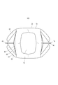
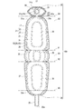
 図4に示すように、胴部11は、収容領域17を間に挟んで互いに対向している第1面状部20a(前側のパネル)及び第2面状部20b(後側のパネル)を有する。第1面状部20aは正面側に位置しており、第2面状部20bは背面側に位置している(図1、図2も参照)。
 第1面状部20aは、例えば、左右対称に形成されており、第2面状部20bも、例えば、左右対称に形成されている。また、第1面状部20aと第2面状部20bとは、例えば、充填部60の後述する接続部65を除き、前後対称に形成されている。
 第1面状部20aは、前方に向けて凸に膨出しており、第2面状部20bは、後方に向けて凸に膨出している。尤も、第1面状部20a、第2面状部20bは、膨出せずに略平面であっても構わない。
 容器本体20は、本体構成シート材21(図8、図9参照)を折り曲げて当該本体構成シート材21の周縁部どうしを相互に接合(本実施形態の場合、内袋40を構成する内袋構成シート材41を介して相互に接合)することによって構成されている。
 容器本体20は、マチ部(天マチ14)側から反対側(底マチ13側)に向けて、互いに並列に延在している一対の縁辺部29a、29bを備えている。縁辺部29a、29bは、容器本体20における左右の側縁部である。
The front shape of the body portion 11 is not particularly limited, but in the case of the present embodiment, for example, as shown in FIG. 2, the body portion 11 has a vertically long shape having a substantially constant width dimension, and the upper edge of the body portion 11 is upward. It is formed in a convex arc shape.
As shown in FIG. 4, the body portion 11 has a first surface-shaped portion 20a (front panel) and a second surface-shaped portion 20b (rear panel) facing each other with the accommodating area 17 in between. Have. The first planar portion 20a is located on the front side, and the second planar portion 20b is located on the back side (see also FIGS. 1 and 2).
The first planar portion 20a is formed symmetrically, for example, and the second planar portion 20b is also formed symmetrically, for example. Further, the first planar portion 20a and the second planar portion 20b are formed symmetrically in the front-rear direction except for, for example, the connecting portion 65 described later of the filling portion 60.
The first planar portion 20a bulges convexly toward the front, and the second planar portion 20b bulges convexly toward the rear. However, the first planar portion 20a and the second planar portion 20b may be substantially flat without bulging.
The container main body 20 is formed by bending the main body constituent sheet material 21 (see FIGS. 8 and 9) and joining the peripheral edges of the main body constituent sheet material 21 to each other (in the case of the present embodiment, the inner bag constituting the inner bag 40). It is configured by joining each other via a constituent sheet material 41).
The container body 20 includes a pair of edge portions 29a and 29b extending in parallel with each other from the gusset portion (top gusset 14) side to the opposite side (bottom gusset 13 side). The edge portions 29a and 29b are the left and right side edge portions of the container body 20.
 天マチ14の平面形状は、特に限定されないが、本実施形態の場合、天マチ14は、図3に示すように、横幅方向における中央部から左方に向かうにつれて前後幅が縮小するとともに、横幅方向における中央部から右方に向かうにつれて前後幅が縮小する形状に形成されている。天マチ14は、例えば、横長の扁桃形状に形成されている。 The planar shape of the heavenly gusset 14 is not particularly limited, but in the case of the present embodiment, as shown in FIG. It is formed in a shape in which the front-rear width decreases from the central part in the direction toward the right. The heaven gusset 14 is formed, for example, in a horizontally long tonsil shape.
 容器本体20は、天マチ14の周縁に沿って配置されているマチ部周縁シール片45と、胴部11の左右の縁辺部29a、29bに沿ってそれぞれ上下に延在し、第1面状部20aの周縁部と第2面状部20bの周縁部との接合部を含む一対の側部シール片46と、を備えている。マチ部周縁シール片45及び側部シール片46は、例えば、容器本体20の外方に向けて起立している。マチ部周縁シール片45及び側部シール片46の延在方向に対して直交する方向におけるマチ部周縁シール片45及び側部シール片46の寸法(マチ部周縁シール片45及び側部シール片46の幅寸法)は、例えば、略一定となっている。 The container body 20 extends vertically along the gusset peripheral edge seal piece 45 arranged along the peripheral edge of the gusset 14 and the left and right edge portions 29a and 29b of the body portion 11, respectively, and has a first surface shape. A pair of side seal pieces 46 including a joint portion between the peripheral edge portion of the portion 20a and the peripheral edge portion of the second planar portion 20b are provided. The gusset peripheral peripheral seal piece 45 and the side seal piece 46 stand, for example, toward the outside of the container body 20. Dimensions of the gusset peripheral edge seal piece 45 and the side seal piece 46 in the direction orthogonal to the extending direction of the gusset peripheral edge seal piece 45 and the side seal piece 46 (the gusset peripheral edge seal piece 45 and the side seal piece 46) Width dimension) is, for example, substantially constant.
 マチ部周縁シール片45は、例えば、後述する接続部65が存在する部位を除き、天マチ14を周回状に取り囲んでいる。
 マチ部周縁シール片45には、マチ部(天マチ14)と第1面状部20aとの境界に沿って配置され、マチ部(天マチ14)の周縁部と第1面状部20aの周縁部との接合部を含む第1面状部側シール片45aと、マチ部と第2面状部20bとの境界に沿って配置され、マチ部(天マチ14)の周縁部と第2面状部20bの周縁部との接合部を含む第2面状部側シール片45bと、が含まれている。
 第1面状部側シール片45aは、マチ部の周縁部と第1面状部20aの周縁部との接合部の内縁に沿って、外側フィルム層22と内側フィルム層23とを接合する本体シール部26を有し、第2面状部側シール片45bは、マチ部の周縁部と第2面状部20bの周縁部との接合部の内縁に沿って、外側フィルム層22と内側フィルム層23とを接合する本体シール部26を有している(図10参照)。なお、図10には、便宜的に、第1面状部側シール片45aを構成する本体シール部26と、第2面状部側シール片45bを構成する本体シール部26に、それぞれ符号を付している。ここで、マチ部の周縁部と第1面状部20aの周縁部との接合部、並びに、マチ部の周縁部と第2面状部20bの周縁部との接合部は、後述する本体シール部28の形成領域の一部分ずつであり、容器本体20の外方に向けて起立した起立片となっている。すなわち、本実施形態の場合、マチ部周縁シール片45(第1面状部側シール片45a及び第2面状部側シール片45b)は、容器本体20の外方に向けて起立している起立片と、当該起立片に連続している(起立片よりも内側に位置している)本体シール部26と、を含んでいる。
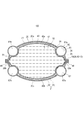
 図3に示すように、マチ部充填部64は、第1面状部側シール片45aから第2面状部側シール片45bに亘って配置されている。すなわち、マチ部充填部64の前縁は、第1面状部側シール片45aによって画定されており、マチ部充填部64の後縁は、第2面状部側シール片45bによって画定されている。これにより、マチ部周縁シール片45によって、マチ部充填部64の外縁が画定されている。ここで、「マチ部充填部64の外縁が画定されている」とは、マチ部充填部64の外縁の90%以上(環状の外縁の総延長の90%以上)が、マチ部周縁シール片45によって取り囲まれていることをいう。本実施形態の場合、接続部65が存在する部位を除き、マチ部充填部64の外縁がマチ部周縁シール片45によって取り囲まれている。
 このため、マチ部充填部64の形成領域がより大きい構造となるため、マチ部充填部64によってより良好に天マチ14を補強することができ、天マチ14の形態安定性が更に向上する。
 また、図3、図4及び図6(a)に示すように、マチ部充填部64は、吐出口に近い側の内縁(例えば、円環状の内縁)を有し、この内縁から、第1面状部側シール片45a、第2面状部側シール片45bおよび側部シール片46の交点92へ向かって下方に延びている。このように、マチ部充填部64が下方に延びる部位を有することによって、例えば容器100がポンプ容器である場合に、ポンピング操作を安定的に行うことが可能となる。また、容器100を浴室などに置いた場合に、マチ部に水などが溜まることを抑制することが出来る。
 より詳細には、マチ部充填部64は、円環状の内縁から、左右両側に向かう部分が、それぞれ交点92へ向かって下方に延びている。一例として、正面視(又は背面視)したときのマチ部充填部64の上縁の形状は、図6(a)に示すように、弧状に湾曲(膨出)した形状を有しながら、マチ部充填部64の中心位置は交点92へ向かって下方に延びている。より詳細には、マチ部充填部64において、吐出口の右側(向かって右側)に位置する部分は、右上に向けて凸に膨出した湾曲形状となっており、吐出口の左側(向かって左側)に位置する部分は、左上に向けて凸に膨出した湾曲形状となっている。
The gusset peripheral peripheral seal piece 45 surrounds the gusset 14 in a circumferential shape, except for a portion where a connecting portion 65, which will be described later, is present.
The gusset peripheral edge seal piece 45 is arranged along the boundary between the gusset portion (heavenly gusset 14) and the first surface-shaped portion 20a, and is formed on the peripheral edge portion of the gusset portion (heavenly gusset 14) and the first surface-shaped portion 20a. The first surface-shaped portion side seal piece 45a including the joint portion with the peripheral portion is arranged along the boundary between the gusset portion and the second planar portion 20b, and the peripheral portion and the second surface portion of the gusset portion (heavenly gusset 14) are arranged. A second surface-shaped portion side seal piece 45b including a joint portion with the peripheral edge portion of the planar portion 20b is included.
The first surface-shaped portion side seal piece 45a is a main body that joins the outer film layer 22 and the inner film layer 23 along the inner edge of the joint portion between the peripheral edge portion of the gusset portion and the peripheral edge portion of the first planar portion 20a. The second surface-shaped portion side seal piece 45b having the sealing portion 26 has an outer film layer 22 and an inner film along the inner edge of the joint portion between the peripheral edge portion of the gusset portion and the peripheral edge portion of the second planar portion 20b. It has a main body seal portion 26 for joining the layer 23 (see FIG. 10). In FIG. 10, for convenience, the main body seal portion 26 constituting the first surface-shaped portion side seal piece 45a and the main body seal portion 26 constituting the second surface-shaped portion side seal piece 45b are designated by reference numerals. It is attached. Here, the joint portion between the peripheral edge portion of the gusset portion and the peripheral edge portion of the first planar portion 20a, and the joint portion between the peripheral edge portion of the gusset portion and the peripheral edge portion of the second planar portion 20b are main body seals described later. It is a part of the forming region of the portion 28, and is an upright piece that stands up toward the outside of the container body 20. That is, in the case of the present embodiment, the gusset peripheral peripheral seal piece 45 (the first surface side seal piece 45a and the second surface side seal piece 45b) stands up toward the outside of the container body 20. It includes a standing piece and a main body sealing portion 26 that is continuous with the standing piece (located inside the standing piece).
As shown in FIG. 3, the gusset portion filling portion 64 is arranged from the first surface portion side seal piece 45a to the second surface portion side seal piece 45b. That is, the leading edge of the gusset filling portion 64 is defined by the first surface-shaped portion side seal piece 45a, and the trailing edge of the gusset portion filling portion 64 is defined by the second surface-shaped portion side seal piece 45b. There is. As a result, the outer edge of the gusset filling portion 64 is defined by the gusset peripheral peripheral seal piece 45. Here, "the outer edge of the gusset filling portion 64 is defined" means that 90% or more of the outer edge of the gusset filling portion 64 (90% or more of the total length of the annular outer edge) is the gusset peripheral peripheral seal piece. It means that it is surrounded by 45. In the case of the present embodiment, the outer edge of the gusset portion filling portion 64 is surrounded by the gusset portion peripheral edge seal piece 45 except for the portion where the connecting portion 65 exists.
Therefore, since the formation region of the gusset portion filling portion 64 has a larger structure, the gusset portion filling portion 64 can better reinforce the heaven gusset 14, and the morphological stability of the gusset gusset 14 is further improved.
Further, as shown in FIGS. 3, 4 and 6 (a), the gusset filling portion 64 has an inner edge (for example, an annular inner edge) on the side close to the discharge port, and the first from this inner edge. It extends downward toward the intersection 92 of the planar side seal piece 45a, the second planar side seal piece 45b, and the side seal piece 46. By having the gusset portion filling portion 64 having a portion extending downward in this way, for example, when the container 100 is a pump container, the pumping operation can be stably performed. Further, when the container 100 is placed in a bathroom or the like, it is possible to prevent water or the like from accumulating in the gusset portion.
More specifically, in the gusset portion filling portion 64, portions toward both the left and right sides extend downward from the inner edge of the annular shape toward the intersection 92, respectively. As an example, the shape of the upper edge of the gusset portion filling portion 64 when viewed from the front (or rear view) has a shape curved (bulged) in an arc shape as shown in FIG. 6A, and has a gusset. The central position of the portion filling portion 64 extends downward toward the intersection 92. More specifically, in the gusset filling portion 64, the portion located on the right side (toward the right side) of the discharge port has a curved shape that bulges convexly toward the upper right, and is on the left side (toward) of the discharge port. The part located on the left side) has a curved shape that bulges toward the upper left.
 本実施形態の場合、内袋40は、内袋構成シート材41(図9参照)の周縁部における一部分どうしを相互に接合することにより構成されている(図7参照)。すなわち、内袋構成シート材41を折り曲げて当該内袋構成シート材41の周縁部どうしを相互に接合することによって、袋状の内袋40が構成されている。内袋40は、容器本体20によって覆われている。内袋40は、当該内袋40の内部に収容領域17を有する。
 ただし、本発明において、収容領域17を画定する内容器が容器本体20の内側に配置されている場合に、その内容器は、シート材により構成された内袋40に限らず、例えば、ブロー成形により構成されたものであってもよい。
In the case of the present embodiment, the inner bag 40 is configured by joining a part of the inner bag constituent sheet material 41 (see FIG. 9) to each other at the peripheral edge portion (see FIG. 7). That is, the bag-shaped inner bag 40 is formed by bending the inner bag constituent sheet material 41 and joining the peripheral edges of the inner bag constituent sheet material 41 to each other. The inner bag 40 is covered with the container body 20. The inner bag 40 has a storage area 17 inside the inner bag 40.
However, in the present invention, when the inner container defining the storage area 17 is arranged inside the container body 20, the inner container is not limited to the inner bag 40 made of the sheet material, for example, blow molding. It may be composed of.
 内袋40の形状は、特に限定されないが、本実施形態の場合、内袋40は容器本体20と同様の形状に形成されている。
 図7に示すように、内袋40は、収容領域17を間に挟んで正面側に位置する第1主面部40aと背面側に位置する第2主面部40bとを有する。
The shape of the inner bag 40 is not particularly limited, but in the case of the present embodiment, the inner bag 40 is formed in the same shape as the container body 20.
As shown in FIG. 7, the inner bag 40 has a first main surface portion 40a located on the front side and a second main surface portion 40b located on the back side with the accommodating area 17 in between.
 容器100は、例えば、天マチ14を貫通して設けられているスパウト部材15と、スパウト部材15に装着(例えば着脱可能に装着)されているキャップ部70と、を備えている。すなわち、キャップ部70は、吐出口を有する吐出部(例えばスパウト部材15)に装着される。
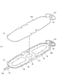
 より詳細には、スパウト部材15は、例えば、図2に示すように、内容物18を通過させる円筒状の注出筒部15aと、注出筒部15aの軸方向における一端(下端)において当該軸方向に対して直交する配置で設けられている板状の板部15bと、を一体に備えて構成されている。注出筒部15aの外周面にはねじ山が形成されており、注出筒部15aは雄ねじ形状となっている。注出筒部15aは、天マチ14を上下に貫通しており、天マチ14から上方に突出している。
 板部15bは、注出筒部15aの下端から周囲に向けてフランジ状に張り出している。板部15bの平面形状は特に限定されないが、例えば、略正方形状であることが挙げられる(図3)。
 板部15bは、例えば、内袋構成シート材41において、胴部11の天マチ14に沿って配置されている部分の内面又は外面に設けられている。板部15bは、例えば、図6(a)及び図6(b)に示すように、天マチ14において内袋構成シート材41の内面152(下面)に対して接合部91において接合されている。このため、板部15bは、内袋構成シート材41を介して、本体構成シート材21に間接的に接合されている。ただし、本発明は、この例に限らず、板部15bは、本体構成シート材21の内側フィルム層23に対して直接接合されていてもよい。接合部91は、平面視において、注出筒部15aの周囲を周回状に取り囲んでいる。接合部91は、マチ部充填部64の内縁を画定している。接合部91の形成領域は、例えば、平面視において、板部15bの外形線よりも内側に収まっている。より詳細には、例えば、挿通穴21aの周囲に位置する円環状の本体シール部26(図10参照)と同じ範囲に形成されている。
 注出筒部15aの先端の開口15cが、収容領域17から内容物18を吐出する吐出口である。板部15bには、注出筒部15aの内空と同軸に開口15dが形成されている。収容領域17内の内容物18は、開口15d及び15cを通して外部に吐出される。
The container 100 includes, for example, a spout member 15 provided so as to penetrate the heaven gusset 14, and a cap portion 70 attached to the spout member 15 (for example, detachably attached). That is, the cap portion 70 is attached to a discharge portion having a discharge port (for example, a spout member 15).
More specifically, the spout member 15 is, for example, at one end (lower end) of the cylindrical pouring cylinder portion 15a through which the content 18 is passed and the pouring cylinder portion 15a in the axial direction, as shown in FIG. It is integrally provided with a plate-shaped plate portion 15b provided in an arrangement orthogonal to the axial direction. A thread is formed on the outer peripheral surface of the dispensing cylinder portion 15a, and the dispensing cylinder portion 15a has a male screw shape. The dispensing cylinder portion 15a penetrates the heavenly gusset 14 up and down, and protrudes upward from the heavenly gusset 14.
The plate portion 15b projects in a flange shape from the lower end of the dispensing cylinder portion 15a toward the periphery. The planar shape of the plate portion 15b is not particularly limited, but for example, it may have a substantially square shape (FIG. 3).
The plate portion 15b is provided on, for example, the inner surface or the outer surface of the portion of the inner bag constituent sheet material 41 that is arranged along the top gusset 14 of the body portion 11. As shown in FIGS. 6A and 6B, for example, the plate portion 15b is joined at the joint portion 91 to the inner surface 152 (lower surface) of the inner bag constituent sheet material 41 in the top gusset 14. .. Therefore, the plate portion 15b is indirectly joined to the main body constituent sheet material 21 via the inner bag constituent sheet material 41. However, the present invention is not limited to this example, and the plate portion 15b may be directly bonded to the inner film layer 23 of the main body constituent sheet material 21. The joint portion 91 surrounds the dispensing cylinder portion 15a in a circular manner in a plan view. The joint portion 91 defines the inner edge of the gusset portion filling portion 64. The formed region of the joint portion 91 is contained inside the outer line of the plate portion 15b in a plan view, for example. More specifically, for example, it is formed in the same range as the annular main body seal portion 26 (see FIG. 10) located around the insertion hole 21a.
The opening 15c at the tip of the dispensing cylinder portion 15a is a discharge port for discharging the contents 18 from the accommodating area 17. An opening 15d is formed in the plate portion 15b coaxially with the inner space of the dispensing cylinder portion 15a. The content 18 in the accommodating area 17 is discharged to the outside through the openings 15d and 15c.
 このように、容器100は、本体構成シート材21に取り付けられている板部15bを有し、吐出口(開口15c)は、板部15bの中央の開口15dを通して内容物18を吐出するようになっている。 In this way, the container 100 has a plate portion 15b attached to the main body constituent sheet material 21, and the discharge port (opening 15c) discharges the content 18 through the central opening 15d of the plate portion 15b. It has become.
 また、板部15bの外面151(上面)が、本体構成シート材21の最内層(本実施形態の場合、内側フィルム層23)に対して直接又は、他のシート材(本実施形態の場合、内袋構成シート材41)を介して間接的に接合されている。
 これにより、図6(a)及び図6(b)に示すように、マチ部充填部64に充填材が封入されている状態において、本体構成シート材21が板部15bの外面151から、板部15bの端面に沿って折れ曲がり、板部15bよりも下方に向かうようにして配置されている。よって、本体構成シート材21によって板部15bひいてはスパウト部材15が周囲から保持される(スパウト部材15の水平移動が規制される)ので、水平方向におけるスパウト部材15の安定性が向上する。
Further, the outer surface 151 (upper surface) of the plate portion 15b is directly with respect to the innermost layer (inner film layer 23 in the case of the present embodiment) of the main body constituent sheet material 21, or another sheet material (in the case of the present embodiment). It is indirectly joined via the inner bag constituent sheet material 41).
As a result, as shown in FIGS. 6A and 6B, in a state where the filler is sealed in the gusset filling portion 64, the main body constituent sheet material 21 is formed from the outer surface 151 of the plate portion 15b. It is arranged so as to bend along the end face of the portion 15b and to face downward from the plate portion 15b. Therefore, the plate portion 15b and thus the spout member 15 are held from the surroundings by the main body constituent sheet material 21 (horizontal movement of the spout member 15 is restricted), so that the stability of the spout member 15 in the horizontal direction is improved.
 また、容器100は、板部15bを本体構成シート材21に対して直接又は、他のシート材を介して間接的に接合している接合部91を有し、接合部91の外縁に沿って、マチ部充填部64の内縁が配置されている。換言すれば、接合部91によってマチ部充填部64の内縁が画定されている。
 このことによっても、水平方向におけるスパウト部材15の安定性が向上する。
Further, the container 100 has a joint portion 91 in which the plate portion 15b is directly or indirectly joined to the main body constituent sheet material 21 via another sheet material, along the outer edge of the joint portion 91. , The inner edge of the gusset filling portion 64 is arranged. In other words, the joint portion 91 defines the inner edge of the gusset portion filling portion 64.
This also improves the stability of the spout member 15 in the horizontal direction.
 本実施形態の場合、接合部91の平面形状は円環状となっている。このため、接合部91の外縁は、外方に向けて凸の曲線部を含む。
 これにより、接合部91の外縁が直線のみにより構成されている場合と比べて、スパウト部材15の傾動が抑制される。
In the case of this embodiment, the planar shape of the joint portion 91 is an annular shape. Therefore, the outer edge of the joint portion 91 includes a curved portion that is convex outward.
As a result, the tilt of the spout member 15 is suppressed as compared with the case where the outer edge of the joint portion 91 is composed of only straight lines.
 接合部91の形成領域は、板部15bの外縁よりも内側に収まっている。このため、図6(a)及び図6(b)に示すように、マチ部充填部64の一部分64bが板部15bの外面151(上面)を覆っている。
 これにより、板部15bが上側からマチ部充填部64によって押さえ付けられることとなるので、板部15b、ひいてはスパウト部材15が上方に変位することが抑制される。
The forming region of the joint portion 91 is contained inside the outer edge of the plate portion 15b. Therefore, as shown in FIGS. 6A and 6B, a part 64b of the gusset filling portion 64 covers the outer surface 151 (upper surface) of the plate portion 15b.
As a result, the plate portion 15b is pressed by the gusset portion filling portion 64 from above, so that the plate portion 15b and eventually the spout member 15 are prevented from being displaced upward.
 更に、マチ部充填部64の他の一部分64aは、例えば、板部15bの内面152(下面)を覆っている。
 これにより、板部15bが下側からマチ部充填部64によって支えられることとなるので、板部15b、ひいてはスパウト部材15が下方に変位することが抑制される。よって、ポンピング操作をより安定的に行うことが可能となる。
Further, the other part 64a of the gusset filling portion 64 covers, for example, the inner surface 152 (lower surface) of the plate portion 15b.
As a result, the plate portion 15b is supported by the gusset portion filling portion 64 from below, so that the plate portion 15b and eventually the spout member 15 are prevented from being displaced downward. Therefore, the pumping operation can be performed more stably.
 キャップ部70は、例えば、注出筒部15aに対して着脱可能に螺合している雌ねじ形状の筒状部である装着部71と、装着部71に固定されているポンプ部72と、ポンプ部72から下方に延出しているディップチューブ77と、ポンプ部72に対して昇降可能にポンプ部72に保持されているヘッド部73と、を備えている。
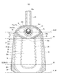
 ヘッド部73は、例えば、ポンプ部72から上方に突出している支持筒部74と、当該ヘッド部73の上端部から水平に突出しているノズル部75と、を有し、ノズル部75の先端には内容物18を吐出する吐出口76が形成されている。
 キャップ部70内における内容物18の流路(不図示)が、開口15d及び開口15cを上下に貫通して配置されている。
 ヘッド部73がポンプ部72に対して押し込まれる(押下される)と、ポンプ部72の働きによって内容物18が吐出口76から吐出されるようになっている。ヘッド部73の押下操作をポンピング操作という。
The cap portion 70 includes, for example, a mounting portion 71 which is a female screw-shaped tubular portion that is detachably screwed to the dispensing cylinder portion 15a, a pump portion 72 fixed to the mounting portion 71, and a pump. It includes a dip tube 77 extending downward from the portion 72, and a head portion 73 held by the pump portion 72 so as to be able to move up and down with respect to the pump portion 72.
The head portion 73 has, for example, a support cylinder portion 74 projecting upward from the pump portion 72 and a nozzle portion 75 projecting horizontally from the upper end portion of the head portion 73, and is provided at the tip of the nozzle portion 75. Is formed with a discharge port 76 for discharging the contents 18.
A flow path (not shown) of the content 18 in the cap portion 70 is arranged so as to vertically penetrate the opening 15d and the opening 15c.
When the head portion 73 is pushed (pressed) with respect to the pump portion 72, the contents 18 are discharged from the discharge port 76 by the action of the pump portion 72. The pressing operation of the head portion 73 is called a pumping operation.
 本実施形態の場合、充填部60は、図1~図5に示すように、例えば、第1面状部20aの周縁部に沿って周回状に形成されている第1充填部61と、第2面状部20bの周縁部に沿って周回状に形成されている第2充填部62と、底マチ13の周縁部に沿って周回状に形成されている第3充填部63(図5)と、天マチ14において注出筒部15aの周囲に周回状に形成されているマチ部充填部64と、を含んでいる。
 第1充填部61の下縁は第3充填部63の前縁と繋がっており、第2充填部62の下縁は第3充填部63の後縁と繋がっており、第1充填部61の上端部の横幅方向における中央部はマチ部充填部64の前端部の横幅方向における中央部と繋がっている。
 容器100は、このような構造の充填部60を備えていることによって、容器本体20のほぼ全体に亘って、構造的強度が十分に確保されている。
 本実施形態の場合、充填部60の全体が一繋がりに形成されている。ここで、第1充填部61とマチ部充填部64との接続部65は、括れている。すなわち、非接合部24において接続部65となる部分である接続部24a(図9、図10)は、括れている。
 なお、本発明において、容器100は、互いに独立した複数の充填部60を備えていても良い。
In the case of the present embodiment, as shown in FIGS. 1 to 5, for example, the filling portion 60 has a first filling portion 61 formed in a circumferential shape along the peripheral edge portion of the first planar portion 20a and a first filling portion 61. A second filling portion 62 formed in a circumferential shape along the peripheral edge portion of the two-sided portion 20b, and a third filling portion 63 formed in a circular shape along the peripheral edge portion of the bottom gusset 13 (FIG. 5). And the gusset portion filling portion 64 formed in a circumferential shape around the pouring cylinder portion 15a in the heaven gusset 14.
The lower edge of the first filling portion 61 is connected to the leading edge of the third filling portion 63, and the lower edge of the second filling portion 62 is connected to the trailing edge of the third filling portion 63. The central portion of the upper end portion in the lateral width direction is connected to the central portion of the front end portion of the gusset portion filling portion 64 in the lateral width direction.
By providing the filling portion 60 having such a structure, the container 100 is sufficiently structurally strong over almost the entire container main body 20.
In the case of the present embodiment, the entire filling portion 60 is formed in a continuous manner. Here, the connecting portion 65 between the first filling portion 61 and the gusset portion filling portion 64 is confined. That is, the connecting portion 24a (FIGS. 9 and 10), which is a portion of the non-joining portion 24 that becomes the connecting portion 65, is constricted.
In the present invention, the container 100 may include a plurality of filling portions 60 that are independent of each other.
 より詳細には、第1充填部61は、例えば、縁辺部29aに沿って上下に延在している第1縁辺充填部61aと、縁辺部29bに沿って上下に延在している第1縁辺充填部61bと、第1縁辺充填部61aの上端と第1縁辺充填部61bの上端とを相互に繋いでいる第1隣接充填部61cと、第1縁辺充填部61aの下端と第1縁辺充填部61bの下端とを相互に繋いでいる第1下縁充填部61dと、を含んで構成されている。
 第1隣接充填部61cは、第1面状部20aの上端部に配置されており、例えば、上方に向けて凸の円弧状に延在している。
 第1下縁充填部61dは、第1面状部20aの下端部に配置されており、例えば、左右に略水平に延在している。
More specifically, the first filling portion 61 includes, for example, a first edge filling portion 61a extending vertically along the edge portion 29a and a first filling portion 61 extending vertically along the edge portion 29b. The edge filling portion 61b, the first adjacent filling portion 61c that connects the upper end of the first edge filling portion 61a and the upper end of the first edge filling portion 61b to each other, the lower end of the first edge filling portion 61a, and the first edge. It is configured to include a first lower edge filling portion 61d that connects the lower ends of the filling portion 61b to each other.
The first adjacent filling portion 61c is arranged at the upper end portion of the first planar portion 20a, and extends upward, for example, in a convex arc shape.
The first lower edge filling portion 61d is arranged at the lower end portion of the first planar portion 20a, and extends substantially horizontally to the left and right, for example.
 同様に、第2充填部62は、例えば、縁辺部29aに沿って上下に延在している第2縁辺充填部62aと、縁辺部29bに沿って上下に延在している第2縁辺充填部62bと、第2縁辺充填部62aの上端と第2縁辺充填部62bの上端とを相互に繋いでいる第2隣接充填部62cと、第2縁辺充填部62aの下端と第2縁辺充填部62bの下端とを相互に繋いでいる第2下縁充填部62dと、を含んで構成されている。
 第2隣接充填部62cは、第2面状部20bの上端部に配置されており、例えば、上方に向けて凸の円弧状に延在している。
第2下縁充填部62dは、第2面状部20bの下端部に配置されており、例えば、左右に略水平に延在している。
 このように、一対の第1縁辺充填部61a、61bのそれぞれの上端を第1隣接充填部61cが繋ぎ、一対の第2縁辺充填部62a、62bのそれぞれの上端を第2隣接充填部62cが繋いでいる。
Similarly, the second filling portion 62 includes, for example, a second edge filling portion 62a extending vertically along the edge portion 29a and a second edge filling portion 62 extending vertically along the edge portion 29b. The second adjacent filling portion 62c that connects the portion 62b, the upper end of the second edge filling portion 62a and the upper end of the second edge filling portion 62b to each other, and the lower end and the second edge filling portion of the second edge filling portion 62a. It is configured to include a second lower edge filling portion 62d that connects the lower ends of 62b to each other.
The second adjacent filling portion 62c is arranged at the upper end portion of the second planar portion 20b, and extends upward, for example, in a convex arc shape.
The second lower edge filling portion 62d is arranged at the lower end portion of the second planar portion 20b, and extends substantially horizontally to the left and right, for example.
In this way, the first adjacent filling portion 61c connects the upper ends of the pair of first edge filling portions 61a and 61b, and the second adjacent filling portion 62c connects the upper ends of the pair of second edge filling portions 62a and 62b. I'm connected.
 図4に示すように、第1縁辺充填部61bの上端611は、マチ部充填部64の一部分の近傍に配置されている。好ましくは、第1縁辺充填部61bの上端611とマチ部充填部64との距離は、上端611における第1縁辺充填部61bの太さD1よりも小さい。例えば、第1縁辺充填部61bの上端611の高さ位置は、マチ部周縁シール片45と側部シール片46の上端との交点92の高さ位置と同じ高さ位置となっている。
 同様に、第2縁辺充填部62bの上端621は、マチ部充填部64における他の一部分の近傍に配置されている。好ましくは、第2縁辺充填部62bの上端621とマチ部充填部64との距離は、上端621における第1縁辺充填部61bの太さD2よりも小さい。例えば、第2縁辺充填部62bの上端621の高さ位置は、マチ部周縁シール片45と側部シール片46の上端との交点92の高さ位置と同じ高さ位置となっている。
 同様に、第1縁辺充填部61aの上端及び第2縁辺充填部62aの上端の各々は、マチ部充填部64における更に一部分の近傍に配置されており、それぞれマチ部充填部64と押圧し合っている。
As shown in FIG. 4, the upper end 611 of the first edge filling portion 61b is arranged in the vicinity of a part of the gusset filling portion 64. Preferably, the distance between the upper end 611 of the first edge filling portion 61b and the gusset filling portion 64 is smaller than the thickness D1 of the first edge filling portion 61b at the upper end 611. For example, the height position of the upper end 611 of the first edge filling portion 61b is the same as the height position of the intersection 92 between the gusset peripheral peripheral seal piece 45 and the upper end of the side seal piece 46.
Similarly, the upper end 621 of the second edge filling portion 62b is arranged in the vicinity of the other part of the gusset filling portion 64. Preferably, the distance between the upper end 621 of the second edge filling portion 62b and the gusset filling portion 64 is smaller than the thickness D2 of the first edge filling portion 61b at the upper end 621. For example, the height position of the upper end 621 of the second edge filling portion 62b is the same as the height position of the intersection 92 between the gusset peripheral peripheral seal piece 45 and the upper end of the side seal piece 46.
Similarly, each of the upper end of the first edge filling portion 61a and the upper end of the second edge filling portion 62a are arranged in the vicinity of a further part of the gusset filling portion 64 and press each other with the gusset filling portion 64. ing.
 このように、容器本体20は、マチ部(天マチ14)側から反対側(底マチ13側)に向けて、互いに並列に延在している一対の縁辺部29a、29bを備え、充填部60には、一対の縁辺部29a、29bの各々に沿って第1面状部20aに形成されている一対の第1縁辺充填部61a、61bと、一対の縁辺部29a、29bの各々に沿って第2面状部20bに形成されている一対の第2縁辺充填部62a、62bと、が含まれている。
 そして、マチ部充填部64の一部分ずつが、一対の第1縁辺充填部61a、61bの各々の近傍と、一対の第2縁辺充填部62a、62bの各々の近傍に、それぞれ配置されている。
 これにより、マチ部充填部64が、第1縁辺充填部61a、61b並びに第2縁辺充填部62a、62bによって良好に支えられることとなるので、マチ部充填部64の形態安定性が更に向上する。
As described above, the container body 20 includes a pair of edge portions 29a and 29b extending in parallel with each other from the gusset portion (top gusset 14) side to the opposite side (bottom gusset 13 side), and the filling portion. In 60, along each of the pair of first edge filling portions 61a and 61b and the pair of edge portions 29a and 29b formed in the first planar portion 20a along each of the pair of edge portions 29a and 29b. A pair of second edge filling portions 62a and 62b formed on the second planar portion 20b are included.
A part of the gusset filling portion 64 is arranged in the vicinity of each of the pair of first edge filling portions 61a and 61b and in the vicinity of each of the pair of second edge filling portions 62a and 62b, respectively.
As a result, the gusset filling portion 64 is satisfactorily supported by the first edge filling portions 61a and 61b and the second edge filling portions 62a and 62b, so that the morphological stability of the gusset filling portion 64 is further improved. ..
 より好ましくは、第1縁辺充填部61bの上端611とマチ部充填部64とは、容器本体20の内部において、(内袋40の一部分を間に挟んで)互いに押圧し合っている。同様に、第1縁辺充填部61aの上端とマチ部充填部64とは、容器本体20の内部において互いに押圧し合っている。
 また、第2縁辺充填部62bの上端621とマチ部充填部64とは、容器本体20の内部において、(内袋40の一部分を間に挟んで)互いに押圧し合っている。同様に、第2縁辺充填部62aの上端とマチ部充填部64とは、容器本体20の内部において互いに押圧し合っている。
 これにより、マチ部充填部64が、第1縁辺充填部61a、61b並びに第2縁辺充填部62a、62bによって一層良好に支えられ、マチ部充填部64の形態安定性が一層向上する。
More preferably, the upper end 611 of the first edge filling portion 61b and the gusset filling portion 64 press against each other (with a part of the inner bag 40 sandwiched between them) inside the container body 20. Similarly, the upper end of the first edge filling portion 61a and the gusset filling portion 64 press against each other inside the container body 20.
Further, the upper end 621 of the second edge filling portion 62b and the gusset filling portion 64 press each other inside the container body 20 (with a part of the inner bag 40 sandwiched between them). Similarly, the upper end of the second edge filling portion 62a and the gusset filling portion 64 press against each other inside the container body 20.
As a result, the gusset portion filling portion 64 is more satisfactorily supported by the first edge filling portions 61a and 61b and the second edge filling portions 62a and 62b, and the morphological stability of the gusset portion filling portion 64 is further improved.
 また、第1隣接充填部61cは、第1面状部側シール片45aに沿って延在している。同様に、第2隣接充填部62cは、第2面状部側シール片45bに沿って延在している。
 すなわち、充填部60には、第1面状部側シール片45aに沿って第1面状部20aに形成されている第1隣接充填部61cと、第2面状部側シール片45bに沿って第2面状部20bに形成されている第2隣接充填部62cと、が含まれている。
 これにより、マチ部充填部64が、第1隣接充填部61c及び第2隣接充填部62cによって良好に支えられることとなるので、マチ部充填部64の形態安定性が更に向上する。
Further, the first adjacent filling portion 61c extends along the first surface-shaped portion side seal piece 45a. Similarly, the second adjacent filling portion 62c extends along the second surface-shaped portion side seal piece 45b.
That is, in the filling portion 60, the first adjacent filling portion 61c formed in the first planar portion 20a along the first planar portion side seal piece 45a and the second planar portion side seal piece 45b are formed in the filling portion 60. A second adjacent filling portion 62c formed on the second planar portion 20b is included.
As a result, the gusset portion filling portion 64 is satisfactorily supported by the first adjacent filling portion 61c and the second adjacent filling portion 62c, so that the morphological stability of the gusset portion filling portion 64 is further improved.
 より好ましくは、第1隣接充填部61cとマチ部充填部64とは、容器本体20の内部において、(内袋40の一部分を間に挟んで)互いに押圧し合っている。同様に、第2隣接充填部62cとマチ部充填部64とは、容器本体20の内部において、(内袋40の一部分を間に挟んで)互いに押圧し合っている。
 これにより、マチ部充填部64が、第1隣接充填部61c及び第2隣接充填部62cによって一層良好に支えられ、マチ部充填部64の形態安定性が一層向上する。
More preferably, the first adjacent filling portion 61c and the gusset filling portion 64 press against each other (with a part of the inner bag 40 sandwiched between them) inside the container main body 20. Similarly, the second adjacent filling portion 62c and the gusset filling portion 64 press against each other (with a part of the inner bag 40 sandwiched between them) inside the container body 20.
As a result, the gusset portion filling portion 64 is more satisfactorily supported by the first adjacent filling portion 61c and the second adjacent filling portion 62c, and the morphological stability of the gusset portion filling portion 64 is further improved.
 図8及び図9に示すように、本体構成シート材21は、容器本体20の外面側を構成する外側フィルム層22と、容器本体20の内面側を構成する内側フィルム層23と、を相互に積層及び接合することにより構成されている。すなわち、一例として、本実施形態の場合、本体構成シート材21は、外側フィルム層22と内側フィルム層23との2層のフィルム層により構成されている。ただし、本発明は、この例に限らず、本体構成シート材21は、外側フィルム層22及び内側フィルム層23以外のフィルム層を有していても良い。
 本実施形態の場合、外側フィルム層22と内側フィルム層23とは互いに同形状に形成されている。ただし、本発明は、この例に限らず、外側フィルム層22と内側フィルム層23とは互いに異形状であっても良い。異形状の場合は、外側フィルム層22は内側フィルム層23よりも大きい形状であることが好ましい。
 外側フィルム層22及び内側フィルム層23には、スパウト部材15の注出筒部15aが挿通される挿通孔が形成されている。
As shown in FIGS. 8 and 9, the main body constituent sheet material 21 mutually has an outer film layer 22 forming the outer surface side of the container main body 20 and an inner film layer 23 forming the inner surface side of the container main body 20. It is configured by laminating and joining. That is, as an example, in the case of the present embodiment, the main body constituent sheet material 21 is composed of two film layers, an outer film layer 22 and an inner film layer 23. However, the present invention is not limited to this example, and the main body constituent sheet material 21 may have a film layer other than the outer film layer 22 and the inner film layer 23.
In the case of the present embodiment, the outer film layer 22 and the inner film layer 23 are formed to have the same shape. However, the present invention is not limited to this example, and the outer film layer 22 and the inner film layer 23 may have different shapes from each other. In the case of a different shape, the outer film layer 22 preferably has a larger shape than the inner film layer 23.
The outer film layer 22 and the inner film layer 23 are formed with insertion holes through which the ejection tube portion 15a of the spout member 15 is inserted.
 本体構成シート材21には、外側フィルム層22と内側フィルム層23とが部分的に非接合とされた非接合部24(図9)が形成されている。例えば、外側フィルム層22又は内側フィルム層23の一方または両方において、他方に対して対向する面には、部分的に非接合処理が施されている。非接合処理は、非接合剤(いわゆる糊殺し剤)を塗布して糊殺し状態とすることによって、容易に形成することができる。糊殺し剤としては、外側フィルム層22と内側フィルム層23との接合を抑制できるものであれば、いかなるものも使用することができる。糊殺し剤としては、例えば、オフセット印刷、フレキソ印刷、レタープレス印刷(凸版印刷)のそれぞれに使用する印刷用インキ、メジウムインキ、糊殺し専用インキ等を好ましく用いることができる。また、熱硬化型や紫外線硬化型のインキを好ましく用いることができる。非接合処理が施された範囲が非接合部24となる。非接合部24に充填材が封入されることによって、充填材が封入された充填部60が形成されるようになっている。
 充填材は、流体(気体または液体)、固体(例えば粉粒体、樹脂ペレット等)または半固体(例えば発泡材等)とすることができ、空気などの気体であることが好ましい。
 充填部60は、必ずしも非接合部24の全部に形成されていることに限定されず、複数ある非接合部24の一部に形成されていてもよい。
 図8では、外側フィルム層22及び内側フィルム層23の各々において、相互に接合されて本体シール部26となる領域には、便宜的に右上がりのハッチングを付している。
 図9及び図10では、本体構成シート材21において、非接合部24を画定するために外側フィルム層22と内側フィルム層23とが相互に接合されている領域、すなわち本体シール部26の形成領域には、便宜的に右上がりのハッチングを付している。
 更に、図9では、本体構成シート材21の周縁部のシール領域と、それ以外の領域と、の境界線であるシール境界線21cを二点鎖線で示している。本実施形態の場合、本体構成シート材21のシール境界線21cよりも外側の領域においては、製袋の際に、外側フィルム層22と内側フィルム層23とが相互に接合されるとともに、内側フィルム層23と内袋構成シート材41とが相互に接合される。
 外側フィルム層22と内側フィルム層23との接合の手法としては、一例として、ヒートシール、超音波シール、接着剤による接合等を用いることができる。
The main body constituent sheet material 21 is formed with a non-bonded portion 24 (FIG. 9) in which the outer film layer 22 and the inner film layer 23 are partially non-bonded. For example, in one or both of the outer film layer 22 and the inner film layer 23, the surface facing the other is partially non-bonded. The non-bonding treatment can be easily formed by applying a non-bonding agent (so-called glue-killing agent) to bring it into a glue-killing state. As the glue killing agent, any agent can be used as long as it can suppress the bonding between the outer film layer 22 and the inner film layer 23. As the glue-killing agent, for example, printing inks, medium inks, glue-killing inks and the like used for each of offset printing, flexographic printing and letter press printing (letterpress printing) can be preferably used. Further, a thermosetting type ink or an ultraviolet curable type ink can be preferably used. The area where the non-joining treatment is applied is the non-joining portion 24. By sealing the filler in the non-joining portion 24, the filling portion 60 in which the filler is sealed is formed.
The filler can be a fluid (gas or liquid), a solid (eg, granules, resin pellets, etc.) or a semi-solid (eg, foam, etc.), and is preferably a gas such as air.
The filling portion 60 is not necessarily formed on all of the non-joining portions 24, and may be formed on a part of a plurality of non-joining portions 24.
In FIG. 8, in each of the outer film layer 22 and the inner film layer 23, a hatching that rises to the right is provided for convenience in the region that is joined to each other to form the main body sealing portion 26.
In FIGS. 9 and 10, in the main body constituent sheet material 21, a region in which the outer film layer 22 and the inner film layer 23 are joined to each other in order to define the non-bonded portion 24, that is, a region where the main body seal portion 26 is formed. Has a hatching that rises to the right for convenience.
Further, in FIG. 9, the seal boundary line 21c, which is the boundary line between the seal region of the peripheral portion of the main body constituent sheet material 21 and the other region, is shown by a two-dot chain line. In the case of the present embodiment, in the region outside the seal boundary line 21c of the main body constituent sheet material 21, the outer film layer 22 and the inner film layer 23 are joined to each other at the time of bag making, and the inner film is formed. The layer 23 and the inner bag constituent sheet material 41 are joined to each other.
As a method of joining the outer film layer 22 and the inner film layer 23, as an example, heat sealing, ultrasonic sealing, bonding with an adhesive, or the like can be used.
 本実施形態の場合、外側フィルム層22及び内側フィルム層23の各々は、複数の樹脂層を含む層構造をなしている。また、内袋構成シート材41も、複数の樹脂層を含む層構造をなしている。 In the case of the present embodiment, each of the outer film layer 22 and the inner film layer 23 has a layer structure including a plurality of resin layers. Further, the inner bag constituent sheet material 41 also has a layer structure including a plurality of resin layers.
 本体構成シート材21は、ポリエチレン系、ポリプロピレン系、ポリエステル系又はポリアミド系のいずれか1種の樹脂層を含んでいることが好ましい。
 本体構成シート材21の外側フィルム層22及び内側フィルム層23を構成する樹脂層の材料は、特に限定されないが、例えば、高密度ポリエチレン(HDPE)、中密度ポリエチレン(MDPE)、低密度ポリエチレン(LDPE)、直鎖状低密度ポリエチレン(LLDPE)、超低密度ポリエチレン(ULDPE)、エチレン-ビニルアルコール共重合体(EVOH)などのポリエチレン系材料、または延伸ポリプロピレン(OPP)、未延伸ポリプロピレン(CPP)、アイソタクチックPP、シンジオタクチックPP、アタクチックPP、ランダムPP、ブロックPPなどのポリプロピレン系材料、またはポリエチレンテレフタレート(PET)、非晶性ポリエチレンテレフタレート(非晶性PET)、ポリブチレンテレフタレート(PBT)、ポリエチレンナフタレート(PEN)、ポリブチレンナフタレート(PBN)などのポリエステル系材料、または延伸ナイロン(ONy)、未延伸ナイロン(CNy)、ナイロン6、ナイロン66、ナイロン11、ナイロン12、MXD6などのポリアミド系材料のいずれかであるのがより好ましく、これらのうち上記ポリエチレン系材料であるのが特に好ましい。
The main body constituent sheet material 21 preferably contains any one of a polyethylene-based, polypropylene-based, polyester-based, and polyamide-based resin layers.
The material of the resin layer constituting the outer film layer 22 and the inner film layer 23 of the main body constituent sheet material 21 is not particularly limited, and is, for example, high-density polyethylene (HDPE), medium-density polyethylene (MDPE), and low-density polyethylene (LDPE). ), Linear low density polyethylene (LLDPE), ultra low density polyethylene (ULDPE), polyethylene-based materials such as ethylene-vinyl alcohol copolymer (EVOH), or stretched polypropylene (OPP), unstretched polypropylene (CPP), Polypropylene-based materials such as isotactic PP, syndiotactic PP, atactic PP, random PP, block PP, or polyethylene terephthalate (PET), amorphous polyethylene terephthalate (acrystalline PET), polybutylene terephthalate (PBT), Polyethylene-based materials such as polyethylene naphthalate (PEN) and polybutylene naphthalate (PBN), or polyamides such as stretched nylon (ONy), unstretched nylon (CNy), nylon 6, nylon 66, nylon 11, nylon 12, MXD6, etc. It is more preferably one of the based materials, and among these, the polyethylene-based material is particularly preferable.
 外側フィルム層22は、一例として、第1層、第2層、第3層及び第4層の4つの樹脂層をこの順に積層することにより構成された4層構造をなしている。
 このうち第1層は、容器本体20の外面を構成する。第1層は、例えば、ポリエチレンテレフタレート(PET)または延伸ナイロン(ONy)により構成されている。第1層の主な機能としては、容器本体20に光沢感及び印刷適性をもたらすとともに容器本体20の剛性を確保することが挙げられる。
 第2層は、例えば、当該第2層における第1層側の面にシリカ及び/又はアルミナが蒸着されたポリエチレンテレフタレートにより構成された透明蒸着PETの層である。第2層の主な機能としては、容器本体20にガスバリア性をもたらすことが挙げられる。
 第3層は、例えば、延伸ナイロンにより構成されている。第3層の主な機能としては、容器本体20の耐ピンホール性を確保することが挙げられる。
 第4層は、例えば、直鎖状低密度ポリエチレン(LLDPE)により構成されている。第4層の主な機能としては、内側フィルム層23とのヒートシール性を確保することが挙げられる。
As an example, the outer film layer 22 has a four-layer structure formed by laminating four resin layers of the first layer, the second layer, the third layer, and the fourth layer in this order.
Of these, the first layer constitutes the outer surface of the container body 20. The first layer is made of, for example, polyethylene terephthalate (PET) or stretched nylon (ONy). The main function of the first layer is to provide the container body 20 with a glossy feeling and printability, and to secure the rigidity of the container body 20.
The second layer is, for example, a layer of transparent vapor-deposited PET composed of polyethylene terephthalate in which silica and / or alumina is vapor-deposited on the surface of the second layer on the first-layer side. The main function of the second layer is to provide the container body 20 with a gas barrier property.
The third layer is made of, for example, stretched nylon. The main function of the third layer is to secure pinhole resistance of the container body 20.
The fourth layer is made of, for example, linear low density polyethylene (LLDPE). The main function of the fourth layer is to secure heat sealability with the inner film layer 23.
 内側フィルム層23の層構造としては、外側フィルム層22の第1層から第4層と同様の層構造に加えて、例えば直鎖状低密度ポリエチレン(LLDPE)により構成されている第5層を備える構造が挙げられる。第5層は、第1層と隣接した層であり、内側フィルム層23における第4層とは反対側の面を構成している。第5層の主な機能としては、外側フィルム層22とのヒートシール性を確保することが挙げられる。
 内側フィルム層23の第4層の主な機能としては、内袋構成シート材41とのヒートシール性を確保することが挙げられる。
 ただし、外側フィルム層22及び内側フィルム層23の層構造は、上記の例に限らず、また、外側フィルム層22及び内側フィルム層23を構成する各層の材料は、上記の例に限らない。
As the layer structure of the inner film layer 23, in addition to the same layer structure as the first to fourth layers of the outer film layer 22, for example, a fifth layer composed of linear low density polyethylene (LLDPE) is used. The structure to be provided can be mentioned. The fifth layer is a layer adjacent to the first layer, and constitutes a surface of the inner film layer 23 opposite to the fourth layer. The main function of the fifth layer is to secure heat sealability with the outer film layer 22.
The main function of the fourth layer of the inner film layer 23 is to secure the heat sealability with the inner bag constituent sheet material 41.
However, the layer structure of the outer film layer 22 and the inner film layer 23 is not limited to the above example, and the material of each layer constituting the outer film layer 22 and the inner film layer 23 is not limited to the above example.
 内袋40を構成する内袋構成シート材41は、一例として、第1層、第2層及び第3層をこの順に積層することにより構成された3層構造をなしている。
 このうち第1層は、例えば、直鎖状低密度ポリエチレンにより構成されている。第1層の主な機能としては、本体構成シート材21とのヒートシール性(内側フィルム層23とのヒートシール性)を確保することが挙げられる。
 第2層は、例えば、当該第2層における第1層側の面にシリカ及び/又はアルミナが蒸着された延伸ナイロンにより構成された透明蒸着延伸ナイロンの層である。第2層の主な機能としては、ガスバリア性及び耐ピンホール性を確保することが挙げられる。
 第3層は、例えば、直鎖状低密度ポリエチレンにより構成されている。第3層の主な機能としては、内袋構成シート材41どうしのヒートシール性を確保することが挙げられる。
 なお、内袋構成シート材41の層構造は、ここで説明した構造に限らない。
As an example, the inner bag constituent sheet material 41 constituting the inner bag 40 has a three-layer structure formed by laminating the first layer, the second layer, and the third layer in this order.
Of these, the first layer is made of, for example, linear low-density polyethylene. The main function of the first layer is to secure heat-sealing property with the main body constituent sheet material 21 (heat-sealing property with the inner film layer 23).
The second layer is, for example, a layer of transparent vapor-deposited stretched nylon composed of stretched nylon in which silica and / or alumina is vapor-deposited on the surface of the second layer on the first layer side. The main function of the second layer is to secure gas barrier properties and pinhole resistance.
The third layer is made of, for example, linear low density polyethylene. The main function of the third layer is to secure the heat sealability between the inner bag constituent sheet materials 41.
The layer structure of the inner bag constituent sheet material 41 is not limited to the structure described here.
 図9及び図10に示すように本体構成シート材21に内袋構成シート材41が積層され、図10に示すように内側フィルム層23の周縁部と内袋構成シート材41の周縁部とが相互に接合されるとともに、外側フィルム層22の周縁部と内側フィルム層23の周縁部とが相互に接合されている。これにより、本体構成シート材21と内袋構成シート材41とにより容器構成シート材51が構成されている。
 ここで、容器構成シート材51の周縁部のシール部を周縁シール部52と称する。周縁シール部52は、内側フィルム層23の周縁部と内袋構成シート材41の周縁部とのシール部(以下、内外シール部43)と、外側フィルム層22の周縁部と内側フィルム層23の周縁部とのシール部(以下、本体シール部28)と、を含む。本体シール部28の形成領域のうち、一部分に、マチ部周縁シール片45が形成されており、他の一部分に、側部シール片46が形成されている。なお、本体シール部28が、非接合部24の外周側を画定するシール部としての機能を兼ねていてもよく、本体シール部28が非接合部24の外周側を画定している領域においては、非接合部24の外周側には、起立片よりも内側に位置していて起立していない本体シール部26が存在していなくてもよい。
 図10において、周縁シール部52の形成領域には、左上がりのハッチングを付している。また、図10において、周縁シール部52の形成領域と本体シール部26の形成領域とが重複している領域では、左上がりのハッチングと右上がりのハッチングとが重なっている。
 周縁シール部52を形成する手法としては、一例として、ヒートシール、超音波シール、接着剤による接合等を用いることができる。
As shown in FIGS. 9 and 10, the inner bag constituent sheet material 41 is laminated on the main body constituent sheet material 21, and as shown in FIG. 10, the peripheral edge portion of the inner film layer 23 and the peripheral edge portion of the inner bag constituent sheet material 41 are formed. In addition to being bonded to each other, the peripheral edge of the outer film layer 22 and the peripheral edge of the inner film layer 23 are bonded to each other. As a result, the container constituent sheet material 51 is composed of the main body constituent sheet material 21 and the inner bag constituent sheet material 41.
Here, the sealing portion of the peripheral edge portion of the container constituent sheet material 51 is referred to as a peripheral edge sealing portion 52. The peripheral edge sealing portion 52 is a sealing portion between the peripheral edge portion of the inner film layer 23 and the peripheral edge portion of the inner bag constituent sheet material 41 (hereinafter, inner / outer sealing portion 43), and the peripheral edge portion of the outer film layer 22 and the inner film layer 23. Includes a seal portion with the peripheral edge portion (hereinafter, main body seal portion 28). A gusset peripheral peripheral seal piece 45 is formed in a part of the formed region of the main body seal portion 28, and a side seal piece 46 is formed in the other part. The main body sealing portion 28 may also function as a sealing portion that defines the outer peripheral side of the non-joining portion 24, and in a region where the main body sealing portion 28 defines the outer peripheral side of the non-joining portion 24. On the outer peripheral side of the non-joining portion 24, the main body sealing portion 26 located inside the standing piece and not standing may not be present.
In FIG. 10, a hatching that rises to the left is provided in the forming region of the peripheral seal portion 52. Further, in FIG. 10, in the region where the forming region of the peripheral seal portion 52 and the forming region of the main body sealing portion 26 overlap, the hatching that rises to the left and the hatching that rises to the right overlap.
As a method for forming the peripheral seal portion 52, as an example, heat seal, ultrasonic seal, bonding with an adhesive, or the like can be used.
 図10に示すように、本体構成シート材21は、例えば、第1面状部20aを構成する部分である第1シート部31と、第2面状部20bを構成する部分である第2シート部32と、底マチ13を構成する部分である底マチ構成シート部38と、天マチ14を構成する部分である天マチ構成シート部39と、チューブ状の延出部25と、を有する。延出部25は、例えば、第2シート部32から外方に延出している。
 天マチ構成シート部39には、スパウト部材15の注出筒部15aが挿通される挿通穴21aが形成されている。
 本実施形態の場合、非接合部24は、容器100の充填部60の形状と対応する形状に形成されている。
As shown in FIG. 10, the main body constituent sheet material 21 is, for example, a first sheet portion 31 which is a portion constituting the first planar portion 20a and a second sheet which is a portion constituting the second planar portion 20b. It has a portion 32, a bottom gusset constituent sheet portion 38 which is a portion constituting the bottom gusset 13, a heavenly gusset constituent sheet portion 39 which is a portion constituting the heavenly gusset 14, and a tubular extending portion 25. The extending portion 25 extends outward from, for example, the second sheet portion 32.
The top gusset constituent sheet portion 39 is formed with an insertion hole 21a into which the ejection cylinder portion 15a of the spout member 15 is inserted.
In the case of the present embodiment, the non-joining portion 24 is formed in a shape corresponding to the shape of the filling portion 60 of the container 100.
 非接合部24において、マチ部充填部64となる部分24bは、例えば、図10に示すように、挿通穴21aを囲む周回状に形成されている。より詳細には、例えば、部分24bの外縁(外形線)は、天マチ構成シート部39の外形線よりも一回り小さい形状となっており、部分24bの内縁は、挿通穴21aよりも一回り大きい円形となっている。 In the non-joined portion 24, the portion 24b serving as the gusset portion filling portion 64 is formed in a circumferential shape surrounding the insertion hole 21a, for example, as shown in FIG. More specifically, for example, the outer edge (outer line) of the portion 24b has a shape that is one size smaller than the outer line of the top gusset constituent sheet portion 39, and the inner edge of the portion 24b is one size smaller than the insertion hole 21a. It is a large circle.
 本実施形態の場合、内袋構成シート材41は、本体構成シート材21における延出部25を除く部分と同形状に形成されている。
 なお、図9では、内袋構成シート材41のシール境界線41aを便宜的に二点鎖線で示している。シール境界線41aは、内袋構成シート材41が本体構成シート材21と接合(シール)される領域と内袋構成シート材41における他の領域との境界線であるとともに、容器構成シート材51を用いて容器100が形成される際に内袋構成シート材41どうしが接合される領域と内袋構成シート材41における他の領域との境界線である。
 本実施形態の場合、シール境界線41aの位置とシール境界線21cの位置とは互いに対応している(互いに重なっている)。
In the case of the present embodiment, the inner bag constituent sheet material 41 is formed in the same shape as the portion of the main body constituent sheet material 21 excluding the extending portion 25.
In FIG. 9, the seal boundary line 41a of the inner bag constituent sheet material 41 is shown by a two-dot chain line for convenience. The seal boundary line 41a is a boundary line between a region where the inner bag constituent sheet material 41 is joined (sealed) with the main body constituent sheet material 21 and another region in the inner bag constituent sheet material 41, and the container constituent sheet material 51. This is a boundary line between a region where the inner bag constituent sheet materials 41 are joined to each other when the container 100 is formed using the above, and another region in the inner bag constituent sheet material 41.
In the case of the present embodiment, the position of the seal boundary line 41a and the position of the seal boundary line 21c correspond to each other (overlap each other).
 内袋構成シート材41において天マチ構成シート部39と重なる部分には、スパウト部材15の注出筒部15aが挿通される挿通穴41bが形成されている。
 スパウト部材15の板部15bは、例えば、内袋構成シート材41において天マチ構成シート部39と重なっている部分の内面に対して接合されている。注出筒部15aは、内袋構成シート材41の挿通穴41b及び天マチ構成シート部39の挿通穴21aを通してこれらシートの外面側に突出している。
An insertion hole 41b through which the ejection cylinder portion 15a of the spout member 15 is inserted is formed in a portion of the inner bag constituent sheet material 41 that overlaps with the top gusset constituent sheet portion 39.
The plate portion 15b of the spout member 15 is joined to, for example, the inner surface of the portion of the inner bag constituent sheet material 41 that overlaps with the top gusset constituent sheet portion 39. The injection cylinder portion 15a projects toward the outer surface side of the inner bag constituent sheet material 41 through the insertion hole 41b and the top gusset constituent sheet portion 39 through the insertion hole 21a.
 容器構成シート材51が、図10に示す折り曲げ線81、折り曲げ線82及び折り曲げ線84においてそれぞれ谷折りされるとともに、折り曲げ線83及び折り曲げ線85においてそれぞれ山折りされた状態で、容器構成シート材51の周縁部(周縁シール部52)どうし(内袋構成シート材41どうし)が接合されることによって、容器構成シート材51が二重構造の袋状に形成される。ここで、谷折りとは、図10における奥側に向けて凸の折り曲げ方であり、山折りとは、図10における手前側に向けて凸の折り曲げ方である。
 すなわち、内袋構成シート材41の縁部どうしが接合されて内袋シール部42(図1参照)が形成されることにより、内袋構成シート材41によって内袋40が形成されるとともに、内袋40を覆う袋状の容器本体20が形成される。
 内袋構成シート材41どうしの接合の手法としては、一例として、ヒートシール、超音波シール、接着剤による接合等を用いることができる。
 本実施形態の場合、本体シール部28、内袋シール部42及び内外シール部43は、互いに対応する位置(互いに重なる位置)に配置されている。本体シール部28、内袋シール部42及び内外シール部43の総称を周縁シール部19とする(周縁シール部19は、本体シール部28、内袋シール部42及び内外シール部43を含む)。
 このため、本実施形態の場合、マチ部周縁シール片45並びに側部シール片46の各々は、本体シール部28、内袋シール部42及び内外シール部43を含んで構成されている。
 ただし、本発明は、この例に限らず、マチ部周縁シール片45並びに側部シール片46は、本体シール部28のみにより構成されていてもよい。
The container constituent sheet material 51 is valley-folded at the fold line 81, the fold line 82, and the fold line 84 shown in FIG. 10, and is mountain-folded at the fold line 83 and the fold line 85, respectively. By joining the peripheral edges (peripheral seal portions 52) of the 51 to each other (inner bag constituent sheet members 41 to each other), the container constituent sheet members 51 are formed in a double-structured bag shape. Here, the valley fold is a folding method that is convex toward the back side in FIG. 10, and the mountain fold is a folding method that is convex toward the front side in FIG.
That is, the edges of the inner bag constituent sheet material 41 are joined to each other to form the inner bag sealing portion 42 (see FIG. 1), whereby the inner bag 40 is formed by the inner bag constituent sheet material 41 and the inner bag 40 is formed. A bag-shaped container body 20 that covers the bag 40 is formed.
As a method of joining the inner bag constituent sheet materials 41 to each other, as an example, heat sealing, ultrasonic sealing, joining with an adhesive or the like can be used.
In the case of the present embodiment, the main body seal portion 28, the inner bag seal portion 42, and the inner / outer seal portion 43 are arranged at positions corresponding to each other (positions overlapping each other). The main body seal portion 28, the inner bag seal portion 42, and the inner / outer seal portion 43 are collectively referred to as the peripheral seal portion 19 (the peripheral seal portion 19 includes the main body seal portion 28, the inner bag seal portion 42, and the inner / outer seal portion 43).
Therefore, in the case of the present embodiment, each of the gusset peripheral peripheral seal piece 45 and the side seal piece 46 includes a main body seal portion 28, an inner bag seal portion 42, and an inner / outer seal portion 43.
However, the present invention is not limited to this example, and the gusset peripheral peripheral seal piece 45 and the side seal piece 46 may be composed of only the main body seal portion 28.
 第1シート部31において、折り曲げ線85よりも天マチ構成シート部39側の部分は、第1重複部31aである。第1重複部31aは、非接合部24に充填材が充填される前の状態では、天マチ構成シート部39における一方の半部と重なって配置されている。
 第2シート部32において、折り曲げ線86よりも底マチ構成シート部38から遠い側に位置する部分は、第2重複部32aである。第2重複部32aは、非接合部24に充填材が充填される前の状態では、天マチ構成シート部39における他方の半部と重なって配置されている。
In the first sheet portion 31, the portion of the top gusset constituent sheet portion 39 side of the bending line 85 is the first overlapping portion 31a. The first overlapping portion 31a is arranged so as to overlap one half of the top gusset constituent sheet portion 39 in a state before the non-joining portion 24 is filled with the filler.
In the second sheet portion 32, the portion located on the side farther from the bottom gusset constituent sheet portion 38 than the bending line 86 is the second overlapping portion 32a. The second overlapping portion 32a is arranged so as to overlap the other half portion of the top gusset constituent sheet portion 39 in a state before the non-joining portion 24 is filled with the filler.
 こうして、図11に示すように、容器構成シート材51が二重の袋状に形成され、容器100が得られる。容器100は、例えば、延出部25に形成されている注入口25a(図10)から非接合部24に充填材が注入され、その後、延出部25の基端側に連接する部位において非接合部24が封止される。これにより、非接合部24(充填部60)に充填材が封入される。
 なお、充填部60の内部における圧力は、特に限定されないが、大気圧よりも高圧であることが好ましく、例えば、10kPa以上500kPa以下(ゲージ圧)とすることができる。
 すなわち、充填材を封入可能な充填部とは、外側フィルム層22と内側フィルム層23との層間に位置し、10kPa以上500kPa以下程度の圧力で充填材が封入されたときに密閉性を保持することが可能な空間をいう。
 充填材が封入された充填部60の形成後、例えば、延出部25は切除される。
 こうして、充填部60に充填材が封入された容器100が得られる。ただし、充填材が封入された容器100の状態でも延出部25が残留していてもよい。
In this way, as shown in FIG. 11, the container constituent sheet material 51 is formed in a double bag shape, and the container 100 is obtained. In the container 100, for example, the filler is injected into the non-joining portion 24 from the injection port 25a (FIG. 10) formed in the extending portion 25, and then the filling material is not connected to the proximal end side of the extending portion 25. The joint 24 is sealed. As a result, the filler is sealed in the non-joining portion 24 (filling portion 60).
The pressure inside the filling portion 60 is not particularly limited, but is preferably higher than the atmospheric pressure, and can be, for example, 10 kPa or more and 500 kPa or less (gauge pressure).
That is, the filling portion in which the filler can be sealed is located between the outer film layer 22 and the inner film layer 23, and maintains the airtightness when the filler is sealed at a pressure of about 10 kPa or more and 500 kPa or less. A space where it is possible.
After forming the filling portion 60 in which the filler is sealed, for example, the extending portion 25 is cut off.
In this way, the container 100 in which the filler is sealed in the filling portion 60 is obtained. However, the extension portion 25 may remain even in the state of the container 100 in which the filler is sealed.
 容器100の作製後、スパウト部材15の注出筒部15aを通して収容領域17に内容物18を充填した後で、スパウト部材15にキャップ部70が装着されることによって、収容領域17に内容物18が封入された容器100が得られる。 After the container 100 is manufactured, the content 18 is filled in the accommodating area 17 through the pouring cylinder portion 15a of the spout member 15, and then the cap portion 70 is attached to the spout member 15 to fill the accommodating area 17 with the content 18 A container 100 in which is sealed is obtained.
 本発明は上述の実施形態に限定されるものではなく、本発明の目的が達成される限りにおける種々の変形、改良等の態様も含む。 The present invention is not limited to the above-described embodiment, but also includes various modifications, improvements, and the like as long as the object of the present invention is achieved.
 例えば、容器100は、内袋40を備えていなくてもよい。この場合、容器本体20によって収容領域17が構成されている。すなわち、周縁シール部19において、本体構成シート材21の内側フィルム層23の一部分どうしが接合されることによって、容器本体20が形成されるとともに収容領域17が構成されている。
 この場合、例えば、板部15bの外面151は、接合部91により本体構成シート材21の内側フィルム層23に対して直接接合されている。
For example, the container 100 does not have to include the inner bag 40. In this case, the container body 20 constitutes the storage area 17. That is, in the peripheral seal portion 19, the container main body 20 is formed and the accommodating area 17 is formed by joining a part of the inner film layer 23 of the main body constituent sheet material 21 to each other.
In this case, for example, the outer surface 151 of the plate portion 15b is directly joined to the inner film layer 23 of the main body constituent sheet material 21 by the joining portion 91.
 また、上記においては、容器100がポンプ部72を有するポンプ容器である例を説明したが、容器100は、ポンプ容器以外であってもよい。例えば、容器100は、注出筒部15aを閉塞するキャップ(スクリューキャップなど)を有するものであってもよい。
 この場合、容器100は、底マチ13を有していて、吐出口が上向きの姿勢で自立する形態であってもよいし、吐出口が下向きの姿勢(倒立姿勢)で自立する形態であってもよい。前者の場合、上記の実施形態と同様に、天マチ14の上面への水等の滞留を抑制できることから、天マチ14の上面を清浄に維持させることができる。後者の場合、吐出口を有するマチ部の良好な保形性を実現できることから、容器100の倒立姿勢の安定性を確保することができる。
Further, in the above, the example in which the container 100 is a pump container having the pump portion 72 has been described, but the container 100 may be other than the pump container. For example, the container 100 may have a cap (screw cap or the like) that closes the pouring cylinder portion 15a.
In this case, the container 100 may have a bottom gusset 13 and the discharge port may be self-supporting in an upward posture, or the discharge port may be self-supporting in a downward posture (inverted posture). May be good. In the former case, as in the above embodiment, the retention of water or the like on the upper surface of the heavenly gusset 14 can be suppressed, so that the upper surface of the heavenly gusset 14 can be kept clean. In the latter case, since good shape retention of the gusset portion having the discharge port can be realized, the stability of the inverted posture of the container 100 can be ensured.
 また、容器100の各種の構成要素は、個々に独立した存在である必要はなく、複数の構成要素が一個の部材として形成されていること、一つの構成要素が複数の部材で形成されていること、ある構成要素が他の構成要素の一部であること、ある構成要素の一部と他の構成要素の一部とが重複していること、等が許容される。 Further, the various components of the container 100 do not have to be individually independent, and a plurality of components are formed as one member, and one component is formed of a plurality of members. It is permissible that one component is part of another, that part of one component overlaps with some of another component, and so on.
11 胴部
13 底マチ
14 天マチ
15 スパウト部材
15a 注出筒部
15b 板部
15c、15d 開口
17 収容領域
18 内容物
19 周縁シール部
20 容器本体
20a 第1面状部
20b 第2面状部
21 本体構成シート材
22 外側フィルム層
23 内側フィルム層
24 非接合部
26、28 本体シール部
29a、29b 縁辺部
45 マチ部周縁シール片
45a 第1面状部側シール片
45b 第2面状部側シール片
46 側部シール片
51 容器構成シート材
52 周縁シール部
60 充填部
61 第1充填部
61a、61b 第1縁辺充填部
61c 第1隣接充填部
61d 第1下縁充填部
62 第2充填部
62a、62b 第2縁辺充填部
62c 第2隣接充填部
62d 第2下縁充填部
64 マチ部充填部
91 接合部
151 外面
152 内面
100 容器
11 Body 13 Bottom gusset 14 Top gusset 15 Spout member 15a Dispensing cylinder 15b Plate 15c, 15d Opening 17 Containment area 18 Contents 19 Peripheral seal 20 Container body 20a First surface 20b Second surface 21 Main body composition Sheet material 22 Outer film layer 23 Inner film layer 24 Non-bonded parts 26, 28 Main body seal parts 29a, 29b Edge part 45 Machi part peripheral edge seal piece 45a First surface side seal piece 45b Second surface side seal Piece 46 Side seal piece 51 Container constituent sheet material 52 Peripheral seal part 60 Filling part 61 First filling part 61a, 61b First edge filling part 61c First adjacent filling part 61d First lower edge filling part 62 Second filling part 62a , 62b 2nd edge filling part 62c 2nd adjacent filling part 62d 2nd lower edge filling part 64 gusset part filling part 91 joint part 151 outer surface 152 inner surface 100 container

Claims (25)

  1.  内容物を収容する収容領域と、
     複数のフィルム層を積層した本体構成シート材により構成されており、前記収容領域を包囲している容器本体と、
     を備え、
     前記容器本体は、第1面状部と、前記収容領域を間に挟んで前記第1面状部と対向して配置されている第2面状部と、前記第1面状部と前記第2面状部とを相互に繋いでいるマチ部と、を有し、
     前記マチ部には、前記収容領域から前記内容物を吐出する吐出口が設けられており、
     前記本体構成シート材は、前記複数のフィルム層どうしが接合された本体シール部と、前記複数のフィルム層どうしが部分的に非接合とされた非接合部と、を有するとともに、前記非接合部における前記複数のフィルム層どうしの層間に充填材を封入可能な充填部を有し、
     前記充填部には、前記マチ部に配置されているマチ部充填部が含まれ、
     前記本体シール部には、前記マチ部の周縁に沿って配置されているマチ部周縁シール片が含まれ、
     前記マチ部周縁シール片によって、前記マチ部充填部の外縁が画定されている容器。
    A storage area for accommodating the contents and
    A container body that is composed of a main body constituent sheet material in which a plurality of film layers are laminated and surrounds the storage area, and a container main body.
    With
    The container body includes a first planar portion, a second planar portion arranged so as to face the first planar portion with the accommodating area in between, and the first planar portion and the first surface portion. It has a gusset part that connects the two-sided parts to each other,
    The gusset portion is provided with a discharge port for discharging the contents from the accommodation area.
    The main body constituent sheet material has a main body sealing portion in which the plurality of film layers are bonded to each other, and a non-bonded portion in which the plurality of film layers are partially non-bonded, and the non-bonded portion. It has a filling portion capable of encapsulating a filler between the layers of the plurality of film layers in the above.
    The filling portion includes a gusset portion filling portion arranged in the gusset portion.
    The main body seal portion includes a gusset peripheral peripheral seal piece arranged along the peripheral edge of the gusset portion.
    A container in which the outer edge of the gusset filling portion is defined by the gusset peripheral seal piece.
  2.  前記マチ部周縁シール片には、前記マチ部と前記第1面状部との境界に沿って配置されている第1面状部側シール片と、前記マチ部と前記第2面状部との境界に沿って配置されている第2面状部側シール片と、が含まれ、
     前記マチ部充填部は、前記第1面状部側シール片から前記第2面状部側シール片に亘って配置されている請求項1に記載の容器。
    The gusset peripheral peripheral seal piece includes a first surface-shaped portion side seal piece arranged along the boundary between the gusset portion and the first planar portion, and the gusset portion and the second planar portion. The second surface side seal piece, which is arranged along the boundary of the
    The container according to claim 1, wherein the gusset portion filling portion is arranged from the first surface portion side seal piece to the second surface portion side seal piece.
  3.  前記第1面状部側シール片は、前記マチ部の周縁部と前記第1面状部の周縁部との接合部を含み、
     前記第2面状部側シール片は、前記マチ部の周縁部と前記第2面状部の周縁部との接合部を含む請求項2に記載の容器。
    The first surface-shaped portion side seal piece includes a joint portion between the peripheral edge portion of the gusset portion and the peripheral edge portion of the first planar portion.
    The container according to claim 2, wherein the second surface-shaped portion side seal piece includes a joint portion between the peripheral edge portion of the gusset portion and the peripheral edge portion of the second planar portion.
  4.  前記本体構成シート材は、前記容器本体の外面側を構成する外側フィルム層と、前記容器本体の内面側を構成する内側フィルム層と、を相互に積層及び接合することにより構成されている請求項3に記載の容器。 A claim that the main body constituent sheet material is formed by laminating and joining an outer film layer constituting the outer surface side of the container body and an inner film layer forming the inner surface side of the container body to each other. The container according to 3.
  5.  前記第1面状部側シール片は、前記マチ部の周縁部と前記第1面状部の周縁部との前記接合部の内縁に沿って、前記外側フィルム層と前記内側フィルム層とを接合する前記本体シール部を有し、
     前記第2面状部側シール片は、前記マチ部の周縁部と前記第2面状部の周縁部との前記接合部の内縁に沿って、前記外側フィルム層と前記内側フィルム層とを接合する前記本体シール部を有している請求項4に記載の容器。
    The first surface-shaped portion side seal piece joins the outer film layer and the inner film layer along the inner edge of the joint portion between the peripheral edge portion of the gusset portion and the peripheral edge portion of the first planar portion. Has the main body seal part to be
    The second surface-shaped portion side seal piece joins the outer film layer and the inner film layer along the inner edge of the joint portion between the peripheral edge portion of the gusset portion and the peripheral edge portion of the second planar portion. The container according to claim 4, which has the main body sealing portion.
  6.  前記充填部には、前記第1面状部側シール片に沿って前記第1面状部に形成されている第1隣接充填部と、前記第2面状部側シール片に沿って前記第2面状部に形成されている第2隣接充填部と、が含まれている請求項2から5のいずれか一項に記載の容器。 The filling portion includes a first adjacent filling portion formed in the first surface-shaped portion along the first surface-shaped portion side seal piece, and the second filling portion along the second surface-shaped portion side seal piece. The container according to any one of claims 2 to 5, which includes a second adjacent filling portion formed in a two-sided portion.
  7.  前記第1隣接充填部と前記マチ部充填部とは、前記容器本体の内部において、互いに押圧し合っており、前記第2隣接充填部と前記マチ部充填部とは、前記容器本体の内部において、互いに押圧し合っている請求項6に記載の容器。 The first adjacent filling portion and the gusset filling portion are pressed against each other inside the container body, and the second adjacent filling portion and the gusset filling portion are inside the container body. The container according to claim 6, wherein the containers are pressed against each other.
  8.  前記容器本体は、前記マチ部側から反対側に向けて、互いに並列に延在している一対の縁辺部を備え、
     前記充填部には、前記一対の縁辺部の各々に沿って前記第1面状部に形成されている一対の第1縁辺充填部と、前記一対の縁辺部の各々に沿って前記第2面状部に形成されている一対の第2縁辺充填部と、が含まれ、
     前記マチ部充填部の一部分ずつが、前記一対の第1縁辺充填部の各々の近傍と、前記一対の第2縁辺充填部の各々の近傍に、それぞれ配置されている請求項6又は7に記載の容器。
    The container body includes a pair of edge portions extending in parallel with each other from the gusset portion side to the opposite side.
    The filling portion includes a pair of first edge filling portions formed in the first surface-like portion along each of the pair of edge portions, and the second surface along each of the pair of edge portions. A pair of second edge filling portions formed in the shape portion and
    6. Container.
  9.  前記一対の第1縁辺充填部のそれぞれの上端を第1隣接充填部が繋ぎ、前記一対の第2縁辺充填部のそれぞれの上端を第2隣接充填部が繋いでいる請求項8に記載の容器。 The container according to claim 8, wherein the first adjacent filling portion connects the upper ends of each of the pair of first edge filling portions, and the second adjacent filling portion connects the upper ends of each of the pair of second edge filling portions. ..
  10.  前記第1隣接充填部は、上方に向けて凸の円弧状に延在し、前記第2隣接充填部は、上方に向けて凸の円弧状に延在している請求項6から9のいずれか一項に記載の容器。 Any of claims 6 to 9, wherein the first adjacent filling portion extends upward in a convex arc shape, and the second adjacent filling portion extends upward in a convex arc shape. The container described in item 1.
  11.  前記容器本体は、前記マチ部側から反対側に向けて、互いに並列に延在している一対の縁辺部を備え、
     前記充填部には、前記一対の縁辺部の各々に沿って前記第1面状部に形成されている一対の第1縁辺充填部と、前記一対の縁辺部の各々に沿って前記第2面状部に形成されている一対の第2縁辺充填部と、が含まれ、
     前記マチ部充填部の一部分ずつが、前記一対の第1縁辺充填部の各々の近傍と、前記一対の第2縁辺充填部の各々の近傍に、それぞれ配置されている請求項1から5のいずれか一項に記載の容器。
    The container body includes a pair of edge portions extending in parallel with each other from the gusset portion side to the opposite side.
    The filling portion includes a pair of first edge filling portions formed in the first surface-like portion along each of the pair of edge portions, and the second surface along each of the pair of edge portions. A pair of second edge filling portions formed in the shape portion and
    Any of claims 1 to 5, wherein each part of the gusset filling portion is arranged in the vicinity of each of the pair of first edge filling portions and in the vicinity of each of the pair of second edge filling portions. The container described in item 1.
  12.  前記第1縁辺充填部の上端と前記マチ部充填部とは、前記容器本体の内部において、互いに押圧し合っており、前記第2縁辺充填部の上端と前記マチ部充填部とは、前記容器本体の内部において互いに押圧し合っている請求項11に記載の容器。 The upper end of the first edge filling portion and the gusset filling portion are pressed against each other inside the container body, and the upper end of the second edge filling portion and the gusset filling portion are the container. The container according to claim 11, wherein the containers are pressed against each other inside the main body.
  13.  内容物を収容する収容領域と、
     複数のフィルム層を積層した本体構成シート材により構成されており、前記収容領域を包囲している容器本体と、
     を備え、
     前記容器本体は、第1面状部と、前記収容領域を間に挟んで前記第1面状部と対向して配置されている第2面状部と、前記第1面状部と前記第2面状部とを相互に繋いでいるマチ部と、を有し、
     前記マチ部には、前記収容領域から前記内容物を吐出する吐出口が設けられており、
     前記本体構成シート材は、前記複数のフィルム層どうしが接合された本体シール部と、前記複数のフィルム層どうしが部分的に非接合とされた非接合部と、を有するとともに、前記非接合部における前記複数のフィルム層どうしの層間に充填材が封入可能な充填部を有し、
     前記充填部には、前記マチ部に配置されているマチ部充填部が含まれ、
     前記容器本体は、
     前記マチ部の周縁部と前記第1面状部の周縁部との接合部を含む第1面状部側シール片と、前記マチ部の周縁部と前記第2面状部の周縁部との接合部を含む第2面状部側シール片と、を備えるマチ部周縁シール片と、
     前記第1面状部の周縁部と前記第2面状部の周縁部との接合部を含む一対の側部シール片と、を有し、
     前記マチ部充填部は、前記吐出口に近い側の内縁を有し、前記内縁から前記第1面状部側シール片、第2面状部側シール片および前記側部シール片の交点へ向かって下方に延びている容器。
    A storage area for accommodating the contents and
    A container body that is composed of a main body constituent sheet material in which a plurality of film layers are laminated and surrounds the storage area, and a container main body.
    With
    The container body includes a first planar portion, a second planar portion arranged so as to face the first planar portion with the accommodating area in between, and the first planar portion and the first surface portion. It has a gusset part that connects the two-sided parts to each other,
    The gusset portion is provided with a discharge port for discharging the contents from the accommodation area.
    The main body constituent sheet material has a main body sealing portion in which the plurality of film layers are bonded to each other, and a non-bonded portion in which the plurality of film layers are partially non-bonded, and the non-bonded portion. Has a filling portion in which a filler can be sealed between the layers of the plurality of film layers in the above.
    The filling portion includes a gusset portion filling portion arranged in the gusset portion.
    The container body
    The first surface-shaped portion side seal piece including the joint portion between the peripheral edge portion of the gusset portion and the peripheral edge portion of the first planar portion, and the peripheral edge portion of the gusset portion and the peripheral edge portion of the second planar portion. A gusset peripheral peripheral seal piece including a second surface side seal piece including a joint portion, and a gusset peripheral edge seal piece.
    It has a pair of side seal pieces including a joint portion between the peripheral edge portion of the first planar portion and the peripheral edge portion of the second planar portion.
    The gusset filling portion has an inner edge on the side close to the discharge port, and faces from the inner edge to the intersection of the first planar side seal piece, the second planar side seal piece, and the side seal piece. A container that extends downward.
  14.  前記本体構成シート材に取り付けられている板部を有し、
     前記吐出口は、前記板部の中央の開口を通して前記内容物を吐出する請求項1から13のいずれか一項に記載の容器。
    It has a plate portion attached to the main body constituent sheet material, and has a plate portion.
    The container according to any one of claims 1 to 13, wherein the discharge port is a container that discharges the contents through a central opening of the plate portion.
  15.  前記板部の外面が、前記本体構成シート材の最内層に対して直接又は、他のシート材を介して間接的に接合されている請求項14に記載の容器。 The container according to claim 14, wherein the outer surface of the plate portion is directly or indirectly joined to the innermost layer of the main body constituent sheet material via another sheet material.
  16.  前記マチ部充填部に充填材が封入されている状態において、前記本体構成シート材が前記板部の前記外面から、前記板部の端面に沿って折れ曲がり、前記板部よりも下方に向かうようにして配置されている請求項15に記載の容器。 In a state where the filler is sealed in the gusset filling portion, the main body constituent sheet material is bent from the outer surface of the plate portion along the end surface of the plate portion so as to face downward from the plate portion. The container according to claim 15, which is arranged in the same manner.
  17.  前記板部を前記本体構成シート材に対して直接又は、他のシート材を介して間接的に接合している接合部を有し、
     前記接合部の外縁に沿って、前記マチ部充填部の内縁が配置されている請求項14から16のいずれか一項に記載の容器。
    It has a joint portion in which the plate portion is directly or indirectly joined to the main body constituent sheet material via another sheet material.
    The container according to any one of claims 14 to 16, wherein the inner edge of the gusset filling portion is arranged along the outer edge of the joint portion.
  18.  前記接合部の前記外縁は、外方に向けて凸の曲線部を含む請求項17に記載の容器。 The container according to claim 17, wherein the outer edge of the joint portion includes a curved portion that is convex outward.
  19.  前記接合部の平面形状は円環状となっている請求項17又は18に記載の容器。 The container according to claim 17 or 18, wherein the planar shape of the joint is annular.
  20.  前記マチ部充填部の一部分が前記板部の内面を覆っている請求項14から19のいずれか一項に記載の容器。 The container according to any one of claims 14 to 19, wherein a part of the gusset filling portion covers the inner surface of the plate portion.
  21.  前記マチ部充填部の一部分が前記板部の外面を覆っている請求項14から20のいずれか一項に記載の容器。 The container according to any one of claims 14 to 20, wherein a part of the gusset filling portion covers the outer surface of the plate portion.
  22.  前記容器本体に包囲されている内袋を備え、前記内袋が前記収容領域を有する請求項1から21のいずれか一項に記載の容器。 The container according to any one of claims 1 to 21, which is provided with an inner bag surrounded by the container body, and the inner bag has the storage area.
  23.  前記充填部に充填材が封入されている請求項1から22のいずれか一項に記載の容器。 The container according to any one of claims 1 to 22, wherein a filler is sealed in the filling portion.
  24.  前記マチ部周縁シール片は、前記容器本体の外方に向けて起立している起立片を含んでいる請求項23に記載の容器。 The container according to claim 23, wherein the gusset peripheral peripheral seal piece includes an upright piece that stands up toward the outside of the container body.
  25.  前記吐出口を有する吐出部に装着されるキャップ部を有し、
     前記キャップ部は、ポンプ部と、該ポンプ部から下方に延出しているディップチューブと、前記ポンプ部に対して昇降可能に該ポンプ部に保持されているヘッド部と、を備えている請求項1から24のいずれか一項に記載の容器。
    It has a cap portion that is attached to the discharge portion having the discharge port, and has a cap portion.
    The cap portion includes a pump portion, a dip tube extending downward from the pump portion, and a head portion held by the pump portion so as to be able to move up and down with respect to the pump portion. The container according to any one of 1 to 24.
PCT/JP2020/011230 2020-03-13 2020-03-13 Container WO2021181692A1 (en)

Priority Applications (6)

Application Number Priority Date Filing Date Title
CN202080098447.0A CN115279664B (en) 2020-03-13 2020-03-13 container
US17/905,801 US20230114929A1 (en) 2020-03-13 2020-03-13 Container
EP20924406.0A EP4119461A4 (en) 2020-03-13 2020-03-13 Container
JP2022505717A JP7350154B2 (en) 2020-03-13 2020-03-13 container
PCT/JP2020/011230 WO2021181692A1 (en) 2020-03-13 2020-03-13 Container
TW110108515A TW202200457A (en) 2020-03-13 2021-03-10 container

Applications Claiming Priority (1)

Application Number Priority Date Filing Date Title
PCT/JP2020/011230 WO2021181692A1 (en) 2020-03-13 2020-03-13 Container

Publications (1)

Publication Number Publication Date
WO2021181692A1 true WO2021181692A1 (en) 2021-09-16

Family

ID=77672219

Family Applications (1)

Application Number Title Priority Date Filing Date
PCT/JP2020/011230 WO2021181692A1 (en) 2020-03-13 2020-03-13 Container

Country Status (6)

Country Link
US (1) US20230114929A1 (en)
EP (1) EP4119461A4 (en)
JP (1) JP7350154B2 (en)
CN (1) CN115279664B (en)
TW (1) TW202200457A (en)
WO (1) WO2021181692A1 (en)

Citations (6)

* Cited by examiner, † Cited by third party
Publication number Priority date Publication date Assignee Title
JPH08207939A (en) * 1994-11-18 1996-08-13 Hosokawa Yoko:Kk Bag for bag-in-box, and bag-in-box
US20130248540A1 (en) 2010-11-29 2013-09-26 Ian Darby Container, container blank, and method of manufacture
JP2015000726A (en) * 2013-06-13 2015-01-05 凸版印刷株式会社 Self-standing packaging bag
JP2016535707A (en) * 2013-11-06 2016-11-17 ザ プロクター アンド ギャンブル カンパニー Flexible container and manufacturing method thereof
JP2016216046A (en) * 2015-05-14 2016-12-22 凸版印刷株式会社 Liquid package
JP2018144860A (en) * 2017-03-07 2018-09-20 花王株式会社 Sheet material container

Family Cites Families (5)

* Cited by examiner, † Cited by third party
Publication number Priority date Publication date Assignee Title
TW367297B (en) * 1994-11-18 1999-08-21 Hosokawa Yoko Kk Bag for bag-in-box and bag-in-box
EP3483086B1 (en) * 2017-03-07 2021-07-21 Kao Corporation Sheet material container
WO2018163269A1 (en) * 2017-03-07 2018-09-13 花王株式会社 Container
US11148387B2 (en) * 2017-03-07 2021-10-19 Fuji Seal International, Inc. Method for manufacturing intermediate material for soft packaging container, method for manufacturing soft packaging container, and method for manufacturing soft packaging container packaging body
WO2018163270A1 (en) * 2017-03-07 2018-09-13 花王株式会社 Sheet material container

Patent Citations (6)

* Cited by examiner, † Cited by third party
Publication number Priority date Publication date Assignee Title
JPH08207939A (en) * 1994-11-18 1996-08-13 Hosokawa Yoko:Kk Bag for bag-in-box, and bag-in-box
US20130248540A1 (en) 2010-11-29 2013-09-26 Ian Darby Container, container blank, and method of manufacture
JP2015000726A (en) * 2013-06-13 2015-01-05 凸版印刷株式会社 Self-standing packaging bag
JP2016535707A (en) * 2013-11-06 2016-11-17 ザ プロクター アンド ギャンブル カンパニー Flexible container and manufacturing method thereof
JP2016216046A (en) * 2015-05-14 2016-12-22 凸版印刷株式会社 Liquid package
JP2018144860A (en) * 2017-03-07 2018-09-20 花王株式会社 Sheet material container

Non-Patent Citations (1)

* Cited by examiner, † Cited by third party
Title
See also references of EP4119461A4

Also Published As

Publication number Publication date
EP4119461A4 (en) 2023-12-06
JP7350154B2 (en) 2023-09-25
TW202200457A (en) 2022-01-01
US20230114929A1 (en) 2023-04-13
EP4119461A1 (en) 2023-01-18
JPWO2021181692A1 (en) 2021-09-16
CN115279664A (en) 2022-11-01
CN115279664B (en) 2023-09-29

Similar Documents

Publication Publication Date Title
JP6186547B1 (en) Sheet material container
JP6822917B2 (en) Sheet material container
JP6879784B2 (en) Sheet material container
CN109641681B (en) Sheet material container
JP6817809B2 (en) Sheet material container
JP6803306B2 (en) container
JP7212493B2 (en) Container sheet
JP2018144885A (en) Sheet material container
JP2019214398A (en) Sheet material container
WO2021181689A1 (en) Sheet material container
WO2021181692A1 (en) Container
WO2021181690A1 (en) Container
WO2021181691A1 (en) Sheet material container
JP7365222B2 (en) container
JP2021155062A (en) container
JP6543306B2 (en) Sheet material container
JP2020083426A (en) Sheet material container
WO2021224995A1 (en) Sheet material container manufacturing method
JP7480431B2 (en) Sheet material container
JP2021176765A (en) Manufacturing method for sheet material container
JP2021172387A (en) container
JP2022180794A (en) Sheet material container
JP2022102203A (en) Container of sheet material
JP2023039709A (en) Sheet material container
JP2021054537A (en) Sheet material container

Legal Events

Date Code Title Description
121 Ep: the epo has been informed by wipo that ep was designated in this application

Ref document number: 20924406

Country of ref document: EP

Kind code of ref document: A1

ENP Entry into the national phase

Ref document number: 2022505717

Country of ref document: JP

Kind code of ref document: A

WWE Wipo information: entry into national phase

Ref document number: 2020924406

Country of ref document: EP

ENP Entry into the national phase

Ref document number: 2020924406

Country of ref document: EP

Effective date: 20221013

NENP Non-entry into the national phase

Ref country code: DE