WO2021181691A1 - Sheet material container - Google Patents

Sheet material container Download PDF

Info

Publication number
WO2021181691A1
WO2021181691A1 PCT/JP2020/011229 JP2020011229W WO2021181691A1 WO 2021181691 A1 WO2021181691 A1 WO 2021181691A1 JP 2020011229 W JP2020011229 W JP 2020011229W WO 2021181691 A1 WO2021181691 A1 WO 2021181691A1
Authority
WO
WIPO (PCT)
Prior art keywords
sheet material
film layer
material container
filling
face
Prior art date
Application number
PCT/JP2020/011229
Other languages
French (fr)
Japanese (ja)
Inventor
貴博 大塚
大輔 児玉
彰 倉賀野
Original Assignee
花王株式会社
Priority date (The priority date is an assumption and is not a legal conclusion. Google has not performed a legal analysis and makes no representation as to the accuracy of the date listed.)
Filing date
Publication date
Application filed by 花王株式会社 filed Critical 花王株式会社
Priority to CN202080098430.5A priority Critical patent/CN115279663B/en
Priority to US17/906,120 priority patent/US11858708B2/en
Priority to JP2022505716A priority patent/JP7360535B2/en
Priority to EP20924591.9A priority patent/EP4119462A4/en
Priority to PCT/JP2020/011229 priority patent/WO2021181691A1/en
Priority to TW110108518A priority patent/TW202140341A/en
Publication of WO2021181691A1 publication Critical patent/WO2021181691A1/en

Links

Images

Classifications

    • BPERFORMING OPERATIONS; TRANSPORTING
    • B65CONVEYING; PACKING; STORING; HANDLING THIN OR FILAMENTARY MATERIAL
    • B65DCONTAINERS FOR STORAGE OR TRANSPORT OF ARTICLES OR MATERIALS, e.g. BAGS, BARRELS, BOTTLES, BOXES, CANS, CARTONS, CRATES, DRUMS, JARS, TANKS, HOPPERS, FORWARDING CONTAINERS; ACCESSORIES, CLOSURES, OR FITTINGS THEREFOR; PACKAGING ELEMENTS; PACKAGES
    • B65D75/00Packages comprising articles or materials partially or wholly enclosed in strips, sheets, blanks, tubes, or webs of flexible sheet material, e.g. in folded wrappers
    • B65D75/38Articles or materials enclosed in two or more wrappers disposed one inside the other
    • BPERFORMING OPERATIONS; TRANSPORTING
    • B65CONVEYING; PACKING; STORING; HANDLING THIN OR FILAMENTARY MATERIAL
    • B65DCONTAINERS FOR STORAGE OR TRANSPORT OF ARTICLES OR MATERIALS, e.g. BAGS, BARRELS, BOTTLES, BOXES, CANS, CARTONS, CRATES, DRUMS, JARS, TANKS, HOPPERS, FORWARDING CONTAINERS; ACCESSORIES, CLOSURES, OR FITTINGS THEREFOR; PACKAGING ELEMENTS; PACKAGES
    • B65D75/00Packages comprising articles or materials partially or wholly enclosed in strips, sheets, blanks, tubes, or webs of flexible sheet material, e.g. in folded wrappers
    • B65D75/008Standing pouches, i.e. "Standbeutel"
    • BPERFORMING OPERATIONS; TRANSPORTING
    • B65CONVEYING; PACKING; STORING; HANDLING THIN OR FILAMENTARY MATERIAL
    • B65DCONTAINERS FOR STORAGE OR TRANSPORT OF ARTICLES OR MATERIALS, e.g. BAGS, BARRELS, BOTTLES, BOXES, CANS, CARTONS, CRATES, DRUMS, JARS, TANKS, HOPPERS, FORWARDING CONTAINERS; ACCESSORIES, CLOSURES, OR FITTINGS THEREFOR; PACKAGING ELEMENTS; PACKAGES
    • B65D75/00Packages comprising articles or materials partially or wholly enclosed in strips, sheets, blanks, tubes, or webs of flexible sheet material, e.g. in folded wrappers
    • B65D75/52Details
    • B65D75/58Opening or contents-removing devices added or incorporated during package manufacture
    • B65D75/5861Spouts
    • B65D75/5872Non-integral spouts
    • BPERFORMING OPERATIONS; TRANSPORTING
    • B05SPRAYING OR ATOMISING IN GENERAL; APPLYING FLUENT MATERIALS TO SURFACES, IN GENERAL
    • B05BSPRAYING APPARATUS; ATOMISING APPARATUS; NOZZLES
    • B05B11/00Single-unit hand-held apparatus in which flow of contents is produced by the muscular force of the operator at the moment of use
    • B05B11/0005Components or details
    • B05B11/0037Containers
    • BPERFORMING OPERATIONS; TRANSPORTING
    • B05SPRAYING OR ATOMISING IN GENERAL; APPLYING FLUENT MATERIALS TO SURFACES, IN GENERAL
    • B05BSPRAYING APPARATUS; ATOMISING APPARATUS; NOZZLES
    • B05B11/00Single-unit hand-held apparatus in which flow of contents is produced by the muscular force of the operator at the moment of use
    • B05B11/01Single-unit hand-held apparatus in which flow of contents is produced by the muscular force of the operator at the moment of use characterised by the means producing the flow
    • B05B11/10Pump arrangements for transferring the contents from the container to a pump chamber by a sucking effect and forcing the contents out through the dispensing nozzle
    • B05B11/1042Components or details
    • B05B11/1043Sealing or attachment arrangements between pump and container
    • B05B11/1046Sealing or attachment arrangements between pump and container the pump chamber being arranged substantially coaxially to the neck of the container
    • B05B11/1047Sealing or attachment arrangements between pump and container the pump chamber being arranged substantially coaxially to the neck of the container the pump being preassembled as an independent unit before being mounted on the container

Abstract

A sheet material container (100) is configured to comprise one or a plurality of sheet materials including a body-configuring sheet material (21) that has outer-side film layers (22) and inner-side film layers (23) laminated in an alternating manner. The sheet material container (100) comprises a container body (20) surrounding an accommodation region 17 constituted from the body-configuring sheet material (21). The sheet material container (100) also has a body sealing section (26) that is a joining section of the outer-side film layers (22) and the inner-side film layers (23), a filling section (60), and a peripheral edge sealing section (19) in which one or a plurality of sheet materials are folded along a folding line and at which single portions of peripheral edge sections of at least innermost-layer sheet materials are joined together. The accommodation region 17 is defined by the peripheral edge sealing section (19). A first planar section and a second planar section that are adjacent to each other are included in a plurality of planar sections of the container body (20). The filling part (60) includes an inter-surface connection part (65) positioned so as to span the first planar section and the second planar section. At the boundary of the first planar section and the second planar section, an end section (19a) of the peripheral edge sealing part (19) along the folding line is set apart from a boundary position (26a) of the inter-surface connection part (65) and the body sealing section (26).

Description

シート材容器Sheet material container
 本発明は、シート材容器に関する。 The present invention relates to a sheet material container.
 複数のフィルム層が積層され、その層間に空気などの充填材が封入されて充填部が形成されている構造のシート材容器は、例えば、特許文献1に記載されている。特許文献1のシート材容器の充填部は、第1面状部(胴部)と第2面状部(底部)とに跨がって配置されている。
先行技術文献
 特許文献1 特許第6153185号公報
For example, Patent Document 1 describes a sheet material container having a structure in which a plurality of film layers are laminated and a filler such as air is sealed between the layers to form a filler. The filling portion of the sheet material container of Patent Document 1 is arranged so as to straddle the first planar portion (body portion) and the second planar portion (bottom portion).
Prior Art Document Patent Document 1 Japanese Patent No. 6153185
 本発明は、相互に積層された外側フィルム層と内側フィルム層とを有する本体構成シート材を含む1又は複数のシート材を備えて構成されているシート材容器であって、内容物を収容する収容領域と、前記本体構成シート材により構成されており、前記収容領域を包囲している容器本体と、を備え、前記本体構成シート材は、前記外側フィルム層と前記内側フィルム層との接合部である本体シール部と、前記外側フィルム層と前記内側フィルム層とが部分的に非接合とされた非接合部と、を有するとともに、前記非接合部における前記外側フィルム層と前記内側フィルム層との層間に充填材を封入可能なされている充填部を有し、当該シート材容器は、前記1又は複数のシート材が折り曲げ線に沿って折り曲げられるとともに、少なくとも前記1又は複数のシート材のうち最内層のシート材の周縁部における一部分どうしが相互に接合されている周縁シール部を有し、前記周縁シール部によって前記収容領域が画定されており、前記容器本体は、複数の面状部を備えており、前記複数の面状部には、互いに隣り合っている第1面状部と第2面状部とが含まれ、前記充填部は、前記第1面状部と前記第2面状部との境界を介して前記第1面状部と前記第2面状部とに跨がって配置されている面間接続部を含み、前記境界において、前記折り曲げ線に沿った前記周縁シール部の端部が、前記面間接続部と本体シール部との境界位置から離間しているシート材容器に関する。 The present invention is a sheet material container including one or more sheet materials including a main body constituent sheet material having an outer film layer and an inner film layer laminated on each other, and houses the contents. It includes a storage area and a container body that is composed of the main body constituent sheet material and surrounds the storage area, and the main body constituent sheet material is a joint portion between the outer film layer and the inner film layer. It has a main body sealing portion, a non-bonded portion in which the outer film layer and the inner film layer are partially non-bonded, and the outer film layer and the inner film layer in the non-bonded portion. In the sheet material container, the one or more sheet materials are bent along a bending line, and at least one of the one or more sheet materials is formed. The innermost layer has a peripheral seal portion in which a part of the peripheral portion of the sheet material is joined to each other, the accommodating area is defined by the peripheral seal portion, and the container body has a plurality of planar portions. The plurality of planar portions include a first planar portion and a second planar portion that are adjacent to each other, and the filling portion includes the first planar portion and the second surface. The peripheral edge along the bending line includes an inter-plane connecting portion arranged so as to straddle the first planar portion and the second planar portion via a boundary with the shaped portion. The present invention relates to a sheet material container in which the end portion of the seal portion is separated from the boundary position between the face-to-face connection portion and the main body seal portion.
第1実施形態に係るシート材容器の充填材を封入した状態の斜視図である。It is a perspective view of the state in which the filler of the sheet material container which concerns on 1st Embodiment is sealed. 第1実施形態に係るシート材容器の充填材を封入した状態の正面図である。It is a front view of the state in which the filler of the sheet material container which concerns on 1st Embodiment is sealed. 第1実施形態に係るシート材容器の充填材を封入した状態の平面図であり、キャップ部を外した状態を示す。It is a top view of the state which filled with the filler of the sheet material container which concerns on 1st Embodiment, and shows the state which the cap part was removed. 第1実施形態に係るシート材容器の底面図である。It is a bottom view of the sheet material container which concerns on 1st Embodiment. 図2のA-A線に沿った断面図である。It is sectional drawing which follows the AA line of FIG. 図2のB-B線に沿った断面図である。It is sectional drawing along the line BB of FIG. 図6のA-A線に沿った断面図である。It is sectional drawing which follows the AA line of FIG. 本体構成シート材の外側フィルム層と内側フィルム層とを示す分解斜視図である。It is an exploded perspective view which shows the outer film layer and the inner film layer of the main body constitution sheet material. 内袋構成シート材と本体構成シート材とを示す分解斜視図である。It is an exploded perspective view which shows the inner bag constituent sheet material and the main body constituent sheet material. 相互に積層された内袋構成シート材と本体構成シート材とを有する容器構成シート材を示す平面図である。It is a top view which shows the container composition sheet material which has the inner bag composition sheet material and the main body composition sheet material which are laminated with each other. 容器構成シート材の部分拡大図である。It is a partially enlarged view of the container composition sheet material. 第1実施形態に係るシート材容器を示す斜視図であり、充填材を封入する前の状態を示す。It is a perspective view which shows the sheet material container which concerns on 1st Embodiment, and shows the state before sealing the filler. 第2実施形態に係るシート材容器の充填材を封入した状態の平断面図である。It is a plan sectional view of the state in which the filler of the sheet material container which concerns on 2nd Embodiment is sealed. 第2実施形態に係るシート材容器の充填材を封入した状態の側断面図である。It is a side sectional view of the state in which the filler of the sheet material container which concerns on 2nd Embodiment is sealed. 図14のA-A線に沿った断面図である。It is sectional drawing along the line AA of FIG. 第3実施形態に係るシート材容器を構成する容器構成シート材の平面図である。It is a top view of the container structure sheet material which comprises the sheet material container which concerns on 3rd Embodiment. 第3実施形態に係るシート材容器の充填材を封入した状態の平面図である。It is a top view of the state in which the filler of the sheet material container which concerns on 3rd Embodiment is sealed. 変形例1に係るシート材容器の構成を説明するための容器構成シート材の部分拡大図である。It is a partially enlarged view of the container structure sheet material for demonstrating the structure of the sheet material container which concerns on modification 1. FIG. 変形例2に係るシート材容器の構成を説明するための容器構成シート材の部分拡大図である。It is a partially enlarged view of the container structure sheet material for demonstrating the structure of the sheet material container which concerns on modification 2. FIG. 変形例3に係るシート材容器の構成を説明するための容器構成シート材の部分拡大図である。It is a partially enlarged view of the container structure sheet material for demonstrating the structure of the sheet material container which concerns on modification 3. FIG. 変形例4に係るシート材容器の構成を説明するための容器構成シート材の部分拡大図である。It is a partially enlarged view of the container structure sheet material for demonstrating the structure of the sheet material container which concerns on modification 4. FIG. 変形例5に係るシート材容器の構成を説明するための容器構成シート材の部分拡大図である。It is a partially enlarged view of the container structure sheet material for demonstrating the structure of the sheet material container which concerns on modification 5. FIG.
発明の詳細な説明Detailed description of the invention
 本願発明者の検討によれば、特許文献1のシート材容器は、充填部への充填材の充填性に関して改善の余地がある。 According to the study by the inventor of the present application, the sheet material container of Patent Document 1 has room for improvement in terms of the filling property of the filling material in the filling portion.
 本発明は、充填部への充填材の充填性に優れた構造のシート材容器に関する。 The present invention relates to a sheet material container having a structure having an excellent filling property of a filler in a filling portion.
 以下、本発明の好ましい実施形態について、図面を用いて説明する。なお、すべての図面において、同様の構成要素には同一の符号を付し、重複する説明は適宜に省略する。 Hereinafter, preferred embodiments of the present invention will be described with reference to the drawings. In all drawings, similar components are designated by the same reference numerals, and duplicate description will be omitted as appropriate.
 〔第1実施形態〕
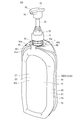
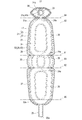
 先ず、図1から図12を用いて第1実施形態を説明する。このうち図1~図7は、充填材が封入された状態のシート材容器100を示す。
[First Embodiment]
First, the first embodiment will be described with reference to FIGS. 1 to 12. Of these, FIGS. 1 to 7 show the sheet material container 100 in a state in which the filler is sealed.
 本実施形態に係るシート材容器100は、相互に積層された外側フィルム層22と内側フィルム層23とを有する本体構成シート材21を含む1又は複数のシート材を備えて構成されているシート材容器100であって、内容物18を収容する収容領域17と、本体構成シート材21により構成されており収容領域17を包囲している容器本体20と、を備えている。本体構成シート材21は、外側フィルム層22と内側フィルム層23との接合部である本体シール部26(図7、図9等)と、外側フィルム層22と内側フィルム層23とが部分的に非接合とされた非接合部24と、を有するとともに、非接合部24における外側フィルム層22と内側フィルム層23との層間に充填材を封入可能な充填部60を有する。当該シート材容器100は、1又は複数のシート材が折り曲げ線81、82、83、84、85、86(図10、図12)に沿って折り曲げられるとともに、少なくとも1又は複数のシート材のうち最内層のシート材(本実施形態の場合、内袋構成シート材41)の周縁部における一部分どうしが相互に接合されている周縁シール部19を有する。周縁シール部19によって収容領域17が画定されている。容器本体20は、複数の面状部を備えており、複数の面状部には、互いに隣り合っている第1面状部(本実施形態の場合、第1主面部20a)と第2面状部(本実施形態の場合、天マチ14)とが含まれている。充填部60は、第1面状部と第2面状部との境界を介して第1面状部と第2面状部とに跨がって配置されている面間接続部65を含む。図7、図11及び図12に示すように、第1面状部と第2面状部との境界において、折り曲げ線84に沿った周縁シール部19の端部19aが、面間接続部65と本体シール部26との境界位置26aから離間している。 The sheet material container 100 according to the present embodiment includes one or a plurality of sheet materials including a main body constituent sheet material 21 having an outer film layer 22 and an inner film layer 23 laminated to each other. The container 100 includes a storage area 17 for accommodating the contents 18, and a container body 20 composed of a main body constituent sheet material 21 and surrounding the storage area 17. The main body constituent sheet material 21 is partially composed of a main body sealing portion 26 (FIGS. 7, 9, etc.) which is a joint portion between the outer film layer 22 and the inner film layer 23, and the outer film layer 22 and the inner film layer 23. It has a non-bonded portion 24 and a filling portion 60 capable of encapsulating a filler between the outer film layer 22 and the inner film layer 23 in the non-bonded portion 24. In the sheet material container 100, one or more sheet materials are bent along the bending lines 81, 82, 83, 84, 85, 86 (FIGS. 10 and 12), and at least one or more sheet materials are included. It has a peripheral edge sealing portion 19 in which parts of the innermost layer sheet material (in the case of the present embodiment, the inner bag constituent sheet material 41) are joined to each other. The accommodating area 17 is defined by the peripheral seal portion 19. The container body 20 includes a plurality of planar portions, and the plurality of planar portions include a first planar portion (first main surface portion 20a in the case of the present embodiment) and a second surface that are adjacent to each other. A shaped portion (in the case of the present embodiment, a heavenly gusset 14) is included. The filling portion 60 includes an inter-plane connecting portion 65 arranged so as to straddle the first planar portion and the second planar portion via a boundary between the first planar portion and the second planar portion. .. As shown in FIGS. 7, 11 and 12, at the boundary between the first planar portion and the second planar portion, the end portion 19a of the peripheral edge sealing portion 19 along the bending line 84 is the face-to-face connecting portion 65. It is separated from the boundary position 26a between the main body seal portion 26 and the main body seal portion 26.
 本実施形態によれば、第1面状部と第2面状部との境界において、折り曲げ線84に沿った周縁シール部19の端部19aが、面間接続部65と本体シール部26との境界位置26aから離間している。このため、第1面状部と第2面状部との境界では、面間接続部65よりも外側の領域(周縁シール部19の端部19aから面間接続部65と本体シール部26との境界位置26aまでの領域)においても、シート材容器100を構成するフィルム層どうしが剥離している構造となっている。これにより、面間接続部65(非接合部24)を構成する外側フィルム層22と内側フィルム層23の動きが規制されにくく、外側フィルム層22と内側フィルム層23との層間の間隙(非接合部24の間隙)を確保しやすくなる。このため、折り曲げ線84に沿って折り曲げられた状態で、充填部60に充填材を充填する際に、第1面状部の充填部60と第2面状部の充填部60との間で容易に充填材が流通可能となり、例えば、第1面状部の充填部60から面間接続部65を介して第2面状部の充填部60へと充填材を容易に充填することができる。すなわち、充填部60への充填材の充填性に優れた構造のシート材容器100を提供することができる。 According to the present embodiment, at the boundary between the first surface-shaped portion and the second surface-shaped portion, the end portion 19a of the peripheral edge sealing portion 19 along the bending line 84 is connected to the face-to-face connecting portion 65 and the main body sealing portion 26. It is separated from the boundary position 26a of. Therefore, at the boundary between the first surface-like portion and the second surface-like portion, the region outside the face-to-face connection portion 65 (from the end portion 19a of the peripheral edge seal portion 19 to the face-to-face connection portion 65 and the main body seal portion 26). Even in the region up to the boundary position 26a), the film layers constituting the sheet material container 100 are separated from each other. As a result, the movements of the outer film layer 22 and the inner film layer 23 constituting the interfaceted connecting portion 65 (non-bonded portion 24) are less likely to be restricted, and the gap between the outer film layer 22 and the inner film layer 23 (non-bonded) is difficult to regulate. It becomes easy to secure the gap of the portion 24). Therefore, when the filling portion 60 is filled with the filler in a state of being bent along the bending line 84, between the filling portion 60 of the first planar portion and the filling portion 60 of the second planar portion. The filler can be easily distributed, and for example, the filler can be easily filled from the filling portion 60 of the first planar portion to the filling portion 60 of the second planar portion via the face-to-face connecting portion 65. .. That is, it is possible to provide the sheet material container 100 having a structure in which the filling material 60 has an excellent filling property.
 本実施形態の場合、シート材容器100は、底部としての底マチ13(図2、図4)を有しており、底マチ13が水平な載置面に載置された状態で自立可能となっている。 In the case of the present embodiment, the sheet material container 100 has a bottom gusset 13 (FIGS. 2 and 4) as a bottom portion, and can stand on its own in a state where the bottom gusset 13 is mounted on a horizontal mounting surface. It has become.
 本実施形態において、シート材容器100の各構成要素の位置関係(上下関係等)の説明は、特に断りのない場合は、シート材容器100を図1及び図2のように自立させた状態での位置関係を説明したものである。ただし、これらの説明における位置関係は、シート材容器100の使用時や製造時の位置関係とは必ずしも一致しない。
 また、シート材容器100の各構成要素の位置関係について、各図に示される位置関係を説明する場合もある。
 シート材容器100の正面側(図2における紙面の手前側)を前方、シート材容器100の背面側(図2における紙面の奥側)を後方といい、シート材容器100の正面に向かって左側(図2における左側)を左方、シート材容器100の正面に向かって右側(図2における右側)を右方という。また、シート材容器100の左右方向を横幅方向という場合がある。
In the present embodiment, unless otherwise specified, the description of the positional relationship (vertical relationship, etc.) of each component of the sheet material container 100 is in a state where the sheet material container 100 is self-supporting as shown in FIGS. 1 and 2. This is an explanation of the positional relationship of. However, the positional relationship in these explanations does not necessarily match the positional relationship at the time of using or manufacturing the sheet material container 100.
In addition, the positional relationship shown in each figure may be described with respect to the positional relationship of each component of the sheet material container 100.
The front side of the sheet material container 100 (the front side of the paper surface in FIG. 2) is referred to as the front side, the back side of the sheet material container 100 (the back side of the paper surface in FIG. 2) is referred to as the rear side, and the left side when facing the front surface of the sheet material container 100. (Left side in FIG. 2) is referred to as left side, and right side (right side in FIG. 2) when facing the front of the sheet material container 100 is referred to as right side. Further, the left-right direction of the sheet material container 100 may be referred to as a width direction.
 本発明において、内容物18の種類は、特に限定されない。内容物18としては、例えば、シャンプー、リンス、ボディーソープ、洗剤、漂白剤、柔軟剤、飲料、食品の他に、エンジンオイル、化学薬品などが挙げられる。
 また、内容物18は、液体(ペースト状のものを含む)であっても良いし、固体(例えば、粒状のもの(顆粒状のものを含む)、或いは粉状のものなど)であっても良い。
 本実施形態の場合、内容物18は、例えば、液体である。
 内容物18が液体の場合には、内容物18の粘度は、例えば30℃において好ましくは1mPa・s以上12万mPa・s以下(B型粘度計で測定。例えば東機産業社製ビスコメーターTV-10又はビスコメーターTVB-10等で測定)であり、より好ましくは1mPa・s以上6万mPa・s以下である。
In the present invention, the type of the content 18 is not particularly limited. Examples of the content 18 include shampoo, conditioner, body soap, detergent, bleach, fabric softener, beverage, food, engine oil, chemicals and the like.
Further, the content 18 may be a liquid (including a paste), a solid (for example, a granular one (including a granular one), a powdery one, etc.). good.
In the case of this embodiment, the content 18 is, for example, a liquid.
When the content 18 is a liquid, the viscosity of the content 18 is preferably 1 mPa · s or more and 120,000 mPa · s or less (measured with a B-type viscometer. For example, Viscometer TV manufactured by Toki Sangyo Co., Ltd.) at 30 ° C. -10 or measured with a viscometer TVB-10 or the like), more preferably 1 mPa · s or more and 60,000 mPa · s or less.
 本実施形態の場合、容器本体20は、胴部11と、胴部11の上側に配置されている天マチ14と、胴部11の下側に配置されている底マチ13と、を有する袋状に形成されている。ただし、本発明は、この例に限らず、容器本体20は、天マチ14を有していなくてもよく、また、底マチ13を有していなくてもよい。
 容器本体20は、収容領域17を包囲している(本実施形態の場合、内袋40を包囲している)。容器本体20はシート材容器100の外殻を構成している。以下では、容器本体20の胴部11、天マチ14及び底マチ13のことを、シート材容器100の胴部11、天マチ14及び底マチ13と称する場合がある。
In the case of the present embodiment, the container body 20 is a bag having a body portion 11, a top gusset 14 arranged on the upper side of the body portion 11, and a bottom gusset 13 arranged on the lower side of the body portion 11. It is formed in a shape. However, the present invention is not limited to this example, and the container body 20 may not have the top gusset 14 and may not have the bottom gusset 13.
The container body 20 surrounds the storage area 17 (in the case of the present embodiment, the inner bag 40 is surrounded). The container body 20 constitutes the outer shell of the sheet material container 100. In the following, the body 11, top gusset 14 and bottom gusset 13 of the container body 20 may be referred to as the body 11, top gusset 14 and bottom gusset 13 of the sheet material container 100.
 胴部11の正面形状は、特に限定されないが、本実施形態の場合、例えば、図2に示すように、横幅寸法が略一定の縦長形状となっており、胴部11の上縁は上方に向けて凸の弧状に形成されている。
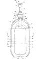
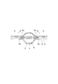
 図5に示すように、胴部11は、収容領域17を間に挟んで互いに対向している第1主面部20a(前側のパネル)及び第2主面部20b(後側のパネル)を有する。第1主面部20aは正面側に位置しており、第2主面部20bは背面側に位置している(図1から図3も参照)。
 第1主面部20aは、例えば、左右対称に形成されており、第2主面部20bも、例えば、左右対称に形成されている。また、第1主面部20aと第2主面部20bとは、例えば、充填部60の後述する面間接続部65を除き、前後対称に形成されている。
 第1主面部20aは、前方に向けて凸に膨出しており、第2主面部20bは、後方に向けて凸に膨出している。
 容器本体20は、本体構成シート材21(図8、図9参照)を折り曲げて当該本体構成シート材21の周縁部どうしを相互に接合(本実施形態の場合、内袋40を構成する内袋構成シート材41を介して相互に接合)することによって構成されている。
The front shape of the body portion 11 is not particularly limited, but in the case of the present embodiment, for example, as shown in FIG. 2, the body portion 11 has a vertically long shape having a substantially constant width dimension, and the upper edge of the body portion 11 is upward. It is formed in a convex arc shape.
As shown in FIG. 5, the body portion 11 has a first main surface portion 20a (front panel) and a second main surface portion 20b (rear panel) facing each other with the accommodating area 17 in between. The first main surface portion 20a is located on the front side, and the second main surface portion 20b is located on the back side (see also FIGS. 1 to 3).
The first main surface portion 20a is formed symmetrically, for example, and the second main surface portion 20b is also formed symmetrically, for example. Further, the first main surface portion 20a and the second main surface portion 20b are formed symmetrically in the front-rear direction except for, for example, the inter-face connection portion 65 of the filling portion 60, which will be described later.
The first main surface portion 20a bulges forward and the second main surface portion 20b bulges rearward.
The container main body 20 is formed by bending the main body constituent sheet material 21 (see FIGS. 8 and 9) and joining the peripheral edges of the main body constituent sheet material 21 to each other (in the case of the present embodiment, the inner bag constituting the inner bag 40). It is configured by joining each other via a constituent sheet material 41).
 天マチ14の平面形状は、特に限定されないが、本実施形態の場合、天マチ14は、図3に示すように、横幅方向における中央部から左方に向かうにつれて前後幅が縮小するとともに、横幅方向における中央部から右方に向かうにつれて前後幅が縮小する形状に形成されている。天マチ14は、例えば、横長の扁桃形状に形成されている。 The planar shape of the heavenly gusset 14 is not particularly limited, but in the case of the present embodiment, as shown in FIG. It is formed in a shape in which the front-rear width decreases from the central part in the direction toward the right. The heaven gusset 14 is formed, for example, in a horizontally long tonsil shape.
 容器本体20は、天マチ14の周縁に沿って配置されているマチ部周縁シール片45と、胴部11の左右の縁辺部に沿ってそれぞれ上下に延在している側部シール片46と、を備えている。マチ部周縁シール片45及び側部シール片46は、例えば、容器本体20の外方に向けて起立している。 The container body 20 includes a gusset peripheral peripheral seal piece 45 arranged along the peripheral edge of the gusset 14 and a side seal piece 46 extending vertically along the left and right edge portions of the body 11. , Is equipped. The gusset peripheral peripheral seal piece 45 and the side seal piece 46 stand, for example, toward the outside of the container body 20.
 マチ部周縁シール片45は、例えば、後述する面間接続部65が存在する部位を除き、天マチ14を周回状に取り囲んでいる。
 マチ部周縁シール片45には、マチ部(天マチ14)と第1主面部20aとの境界に沿って配置されている第1面状部側シール片45aと、マチ部と第2主面部20bとの境界に沿って配置されている第2面状部側シール片45bと、が含まれている。
The gusset peripheral peripheral seal piece 45 surrounds the gusset 14 in a circumferential shape, except for a portion where the inter-face connection portion 65, which will be described later, is present.
The gusset peripheral peripheral seal piece 45 includes a first surface side seal piece 45a arranged along the boundary between the gusset portion (heavenly gusset 14) and the first main surface portion 20a, and the gusset portion and the second main surface portion. The second surface side seal piece 45b, which is arranged along the boundary with the 20b, is included.
 本実施形態の場合、内袋40は、内袋構成シート材41(図9参照)の周縁部における一部分どうしを相互に接合することにより構成されている(図5参照)。すなわち、内袋構成シート材41を折り曲げて当該内袋構成シート材41の周縁部どうしを相互に接合することによって、袋状の内袋40が構成されている。内袋40は、容器本体20によって覆われている。内袋40は、当該内袋40の内部に収容領域17を有する。
 このように、シート材容器100は、容器本体20の内側に配置されている内袋40を備え、内袋40は、シート材容器100を構成する1又は複数のシート材のうち最内層のシート材である内袋構成シート材41により構成されている。
 ただし、本発明において、収容領域17を画定する内容器が容器本体20の内側に配置されている場合に、その内容器は、シート材により構成された内袋40に限らず、例えば、ブロー成形により構成されたものであってもよい。
In the case of the present embodiment, the inner bag 40 is configured by joining a part of the inner bag constituent sheet material 41 (see FIG. 9) to each other at the peripheral edge portion (see FIG. 5). That is, the bag-shaped inner bag 40 is formed by bending the inner bag constituent sheet material 41 and joining the peripheral edges of the inner bag constituent sheet material 41 to each other. The inner bag 40 is covered with the container body 20. The inner bag 40 has a storage area 17 inside the inner bag 40.
As described above, the sheet material container 100 includes an inner bag 40 arranged inside the container body 20, and the inner bag 40 is the innermost sheet of one or a plurality of sheet materials constituting the sheet material container 100. It is composed of an inner bag constituent sheet material 41 which is a material.
However, in the present invention, when the inner container defining the storage area 17 is arranged inside the container body 20, the inner container is not limited to the inner bag 40 made of the sheet material, for example, blow molding. It may be composed of.
 内袋40の形状は、特に限定されないが、本実施形態の場合、内袋40は容器本体20と同様の形状に形成されている。
 図5に示すように、内袋40は、収容領域17を間に挟んで正面側に位置する第1主面部40aと背面側に位置する第2主面部40bとを有する。
The shape of the inner bag 40 is not particularly limited, but in the case of the present embodiment, the inner bag 40 is formed in the same shape as the container body 20.
As shown in FIG. 5, the inner bag 40 has a first main surface portion 40a located on the front side and a second main surface portion 40b located on the back side with the accommodating area 17 in between.
 シート材容器100は、例えば、天マチ14を貫通して設けられているスパウト部材15と、スパウト部材15に装着(例えば着脱可能に装着)されているキャップ部70と、を備えている。
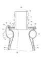
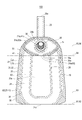
 より詳細には、スパウト部材15は、例えば、図2、図3及び図6に示すように、内容物18を通過させる円筒状の注出筒部15aと、注出筒部15aの軸方向における一端(下端)において当該軸方向に対して直交する配置で設けられている板状の板状部15bと、を一体に備えて構成されている。注出筒部15aの外周面にはねじ山が形成されており、注出筒部15aは雄ねじ形状となっている。注出筒部15aは、天マチ14を上下に貫通しており、天マチ14から上方に突出している。
 板状部15bは、注出筒部15aの下端から周囲に向けてフランジ状に張り出している。板状部15bの平面形状は特に限定されないが、例えば、略正方形状であることが挙げられる(図3)。
 板状部15bは、例えば、内袋構成シート材41において、胴部11の天マチ14に沿って配置されている部分の内面又は外面に設けられている。板状部15bは、例えば、図6に示すように、天マチ14において内袋構成シート材41の内面(下面)に対して接合部91において接合されている。このため、板状部15bは、内袋構成シート材41を介して、本体構成シート材21に接合されている。ただし、本発明は、この例に限らず、板状部15bは、本体構成シート材21の内側フィルム層23に対して直接接合されていてもよい。接合部91は、平面視において、注出筒部15aの周囲を周回状に取り囲んでいる。接合部91は、例えば、挿通穴21aの周囲に位置する円環状の本体シール部26(図10参照)と同じ範囲に形成されている。
 注出筒部15aの先端の開口15cが、収容領域17から内容物18を吐出する吐出口である。板状部15bには、注出筒部15aの内空と同軸に開口15dが形成されている。収容領域17内の内容物18は、開口15d及び開口15cを通して外部に吐出される。
 このように、第2面状部(天マチ14)には、収容領域17から内容物18を吐出する吐出口(開口15c)が設けられている。
 更に、第2面状部(天マチ14)には、吐出口(開口15c)と連通する開口(開口15d)を有する板状部15bが設けられており、板状部15bに対して、上記1又は複数のシート材が接合されている。
The sheet material container 100 includes, for example, a spout member 15 provided so as to penetrate the heaven gusset 14, and a cap portion 70 attached to the spout member 15 (for example, detachably attached).
More specifically, the spout member 15 is, for example, as shown in FIGS. 2, 3 and 6, in the axial direction of the cylindrical pouring cylinder portion 15a through which the content 18 is passed and the pouring cylinder portion 15a. A plate-shaped plate-shaped portion 15b provided at one end (lower end) in an arrangement orthogonal to the axial direction is integrally provided. A thread is formed on the outer peripheral surface of the dispensing cylinder portion 15a, and the dispensing cylinder portion 15a has a male screw shape. The dispensing cylinder portion 15a penetrates the heavenly gusset 14 up and down, and protrudes upward from the heavenly gusset 14.
The plate-shaped portion 15b projects in a flange shape from the lower end of the pouring cylinder portion 15a toward the periphery. The planar shape of the plate-shaped portion 15b is not particularly limited, but for example, it may have a substantially square shape (FIG. 3).
The plate-shaped portion 15b is provided on, for example, the inner surface or the outer surface of the portion of the inner bag constituent sheet material 41 that is arranged along the top gusset 14 of the body portion 11. As shown in FIG. 6, for example, the plate-shaped portion 15b is joined to the inner surface (lower surface) of the inner bag constituent sheet material 41 at the joint portion 91 in the top gusset 14. Therefore, the plate-shaped portion 15b is joined to the main body constituent sheet material 21 via the inner bag constituent sheet material 41. However, the present invention is not limited to this example, and the plate-shaped portion 15b may be directly bonded to the inner film layer 23 of the main body constituent sheet material 21. The joint portion 91 surrounds the dispensing cylinder portion 15a in a circular manner in a plan view. The joint portion 91 is formed in the same range as, for example, the annular main body seal portion 26 (see FIG. 10) located around the insertion hole 21a.
The opening 15c at the tip of the dispensing cylinder portion 15a is a discharge port for discharging the contents 18 from the accommodating area 17. An opening 15d is formed in the plate-shaped portion 15b coaxially with the inner space of the dispensing cylinder portion 15a. The content 18 in the accommodating area 17 is discharged to the outside through the openings 15d and 15c.
As described above, the second planar portion (heavenly gusset 14) is provided with a discharge port (opening 15c) for discharging the content 18 from the accommodating area 17.
Further, the second surface-shaped portion (heaven gusset 14) is provided with a plate-shaped portion 15b having an opening (opening 15d) communicating with the discharge port (opening 15c). One or more sheet materials are joined.
 キャップ部70は、例えば、注出筒部15aに対して着脱可能に螺合している雌ねじ形状の筒状部である装着部71と、装着部71に固定されているポンプ部72と、ポンプ部72から下方に延出しているディップチューブ77と、ポンプ部72に対して昇降可能にポンプ部72に保持されているヘッド部73と、を備えている。
 ヘッド部73は、例えば、ポンプ部72から上方に突出している支持筒部74と、当該ヘッド部73の上端部から水平に突出しているノズル部75と、を有し、ノズル部75の先端には内容物18を吐出する吐出口76が形成されている。
 キャップ部70内における内容物18の流路(不図示)が、開口15d及び開口15cを上下に貫通して配置されている。
 ヘッド部73がポンプ部72に対して押し込まれる(押下される)と、ポンプ部72の働きによって内容物18が吐出口76から吐出されるようになっている。
The cap portion 70 includes, for example, a mounting portion 71 which is a female screw-shaped tubular portion that is detachably screwed to the dispensing cylinder portion 15a, a pump portion 72 fixed to the mounting portion 71, and a pump. It includes a dip tube 77 extending downward from the portion 72, and a head portion 73 held by the pump portion 72 so as to be able to move up and down with respect to the pump portion 72.
The head portion 73 has, for example, a support cylinder portion 74 projecting upward from the pump portion 72 and a nozzle portion 75 projecting horizontally from the upper end portion of the head portion 73, and is provided at the tip of the nozzle portion 75. Is formed with a discharge port 76 for discharging the contents 18.
A flow path (not shown) of the content 18 in the cap portion 70 is arranged so as to vertically penetrate the opening 15d and the opening 15c.
When the head portion 73 is pushed (pressed) with respect to the pump portion 72, the contents 18 are discharged from the discharge port 76 by the action of the pump portion 72.
 本実施形態の場合、充填部60は、図1~図6に示すように、例えば、第1主面部20aの周縁部に沿って周回状に形成されている第1充填部61と、第2主面部20bの周縁部に沿って周回状に形成されている第2充填部62と、底マチ13の周縁部に沿って周回状に形成されている第3充填部63(図4)と、天マチ14において注出筒部15aの周囲に周回状に形成されている第4充填部64(図3)と、を含んでいる。
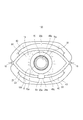
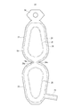
 第1充填部61の下縁は第3充填部63の前縁と繋がっており、第2充填部62の下縁は第3充填部63の後縁と繋がっており、第1充填部61の上端部の横幅方向における中央部は第4充填部64の前端部の横幅方向における中央部と繋がっている。
 シート材容器100は、このような構造の充填部60を備えていることによって、容器本体20のほぼ全体に亘って、構造的強度が十分に確保されている。
 本実施形態の場合、充填部60の全体が一繋がりに形成されている。
 なお、本発明において、シート材容器100は、互いに独立した複数の充填部60を備えていても良い。
In the case of the present embodiment, as shown in FIGS. 1 to 6, for example, the filling portion 60 has a first filling portion 61 formed in a circumferential shape along the peripheral edge portion of the first main surface portion 20a and a second filling portion 61. A second filling portion 62 formed in a circular shape along the peripheral edge portion of the main surface portion 20b, and a third filling portion 63 (FIG. 4) formed in a circular shape along the peripheral edge portion of the bottom gusset 13. The top gusset 14 includes a fourth filling portion 64 (FIG. 3) formed in a circumferential shape around the pouring cylinder portion 15a.
The lower edge of the first filling portion 61 is connected to the leading edge of the third filling portion 63, and the lower edge of the second filling portion 62 is connected to the trailing edge of the third filling portion 63. The central portion of the upper end portion in the lateral width direction is connected to the central portion of the front end portion of the fourth filling portion 64 in the lateral width direction.
By providing the filling portion 60 having such a structure, the sheet material container 100 is sufficiently structurally strong over almost the entire container body 20.
In the case of the present embodiment, the entire filling portion 60 is formed in a continuous manner.
In the present invention, the sheet material container 100 may include a plurality of filling portions 60 that are independent of each other.
 ここで、第1充填部61と第4充填部64との接続部、第1充填部61と第3充填部63との接続部、及び、第2充填部62と第3充填部63との接続部は、それぞれ面間接続部65である。
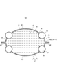
 各面間接続部65は、それぞれ括れている。すなわち、充填部60は、面間接続部65において括れている。非接合部24において面間接続部65となる部分である接続部24a(図9、図10)は、それぞれ括れている。これにより、充填材を封入する際に、面間接続部65を通過する充填材の速度が上がるので、第1面状部の充填部60と第2面状部の充填部60との間で容易に充填材が流通可能となり、シート材容器100における充填部60の全ての領域に、所定量の充填材を容易に充填することができる。
Here, the connection portion between the first filling portion 61 and the fourth filling portion 64, the connecting portion between the first filling portion 61 and the third filling portion 63, and the second filling portion 62 and the third filling portion 63. The connection portions are face-to-face connection portions 65, respectively.
Each face-to-face connection portion 65 is confined. That is, the filling portion 60 is enclosed by the face-to-face connecting portion 65. The connecting portions 24a (FIGS. 9 and 10), which are the portions of the non-joining portions 24 that serve as the face-to-face connecting portions 65, are enclosed. As a result, when the filler is sealed, the speed of the filler passing through the inter-face connection portion 65 increases, so that between the filling portion 60 of the first planar portion and the filling portion 60 of the second planar portion. The filler can be easily distributed, and a predetermined amount of the filler can be easily filled in all the regions of the filling portion 60 in the sheet material container 100.
 本実施形態の場合、容器本体20は、胴部11と天部(天マチ14)とを有し、胴部11の一方の主面部(第1主面部20a)が第1面状部であり、天部が第2面状部である。
 そして、充填部60は、主面部(第1主面部20a)の周縁部に沿って形成されている第1充填部61と、天部(天マチ14)における吐出口の周囲に形成されている第4充填部64と、を有し、第1充填部61と第4充填部64とが、面間接続部65を介して繋がっている。
 しかも、本実施形態の場合、容器本体20は、胴部11と底部(底マチ13)とを有し、胴部11の一方の主面部(第1主面部20a)が第1面状部であり、底部(底マチ13)も第2面状部である。
 そして、充填部60は、主面部の周縁部(第1主面部20a)に沿って形成されている第1充填部61と、底部(底マチ13)の周縁部に沿って形成されている第3充填部63とを有し、第1充填部61と第3充填部63とが、面間接続部65を介して繋がっている。
 更に、本実施形態の場合、胴部11の他方の主面部(第2主面部20b)と底部(底マチ13)も、第1面状部と第2面状部の関係にある。
 各面間接続部65は、シート材容器100の横幅方向における中央部に配置されている。これにより、充填材を封入する際に、充填部60内を均等に充填材が流通するので、充填性が向上する。
In the case of the present embodiment, the container body 20 has a body portion 11 and a top portion (heaven gusset 14), and one main surface portion (first main surface portion 20a) of the body portion 11 is a first surface-shaped portion. , The top is the second surface.
The filling portion 60 is formed around the first filling portion 61 formed along the peripheral edge portion of the main surface portion (first main surface portion 20a) and the discharge port at the top portion (heavenly gusset 14). It has a fourth filling portion 64, and the first filling portion 61 and the fourth filling portion 64 are connected via the face-to-face connecting portion 65.
Moreover, in the case of the present embodiment, the container body 20 has a body portion 11 and a bottom portion (bottom gusset 13), and one main surface portion (first main surface portion 20a) of the body portion 11 is a first surface-shaped portion. Yes, the bottom (bottom gusset 13) is also a second surface.
The filling portion 60 is formed along a first filling portion 61 formed along the peripheral edge portion (first main surface portion 20a) of the main surface portion and a peripheral portion of the bottom portion (bottom gusset 13). It has three filling portions 63, and the first filling portion 61 and the third filling portion 63 are connected via the face-to-face connecting portion 65.
Further, in the case of the present embodiment, the other main surface portion (second main surface portion 20b) and the bottom portion (bottom gusset 13) of the body portion 11 are also in a relationship of the first surface-like portion and the second surface-like portion.
The inter-face connection portion 65 is arranged at the central portion of the sheet material container 100 in the lateral width direction. As a result, when the filler is sealed, the filler is evenly distributed in the filling portion 60, so that the filling property is improved.
 図8及び図9に示すように、本体構成シート材21は、容器本体20の外面側を構成する外側フィルム層22と、容器本体20の内面側を構成する内側フィルム層23と、を相互に積層及び接合することにより構成されている。すなわち、一例として、本実施形態の場合、本体構成シート材21は、外側フィルム層22と内側フィルム層23との2層のフィルム層により構成されている。ただし、本発明は、この例に限らず、本体構成シート材21は、外側フィルム層22及び内側フィルム層23以外のフィルム層を有していても良い。
 本実施形態の場合、外側フィルム層22と内側フィルム層23とは互いに同形状に形成されている。ただし、本発明は、この例に限らず、外側フィルム層22と内側フィルム層23とは互いに異形状であっても良い。異形状の場合は、外側フィルム層22は内側フィルム層23よりも大きい形状であることが好ましい。
 外側フィルム層22及び内側フィルム層23には、スパウト部材15の注出筒部15aが挿通される挿通孔が形成されている。
As shown in FIGS. 8 and 9, the main body constituent sheet material 21 mutually has an outer film layer 22 forming the outer surface side of the container main body 20 and an inner film layer 23 forming the inner surface side of the container main body 20. It is configured by laminating and joining. That is, as an example, in the case of the present embodiment, the main body constituent sheet material 21 is composed of two film layers, an outer film layer 22 and an inner film layer 23. However, the present invention is not limited to this example, and the main body constituent sheet material 21 may have a film layer other than the outer film layer 22 and the inner film layer 23.
In the case of the present embodiment, the outer film layer 22 and the inner film layer 23 are formed to have the same shape. However, the present invention is not limited to this example, and the outer film layer 22 and the inner film layer 23 may have different shapes from each other. In the case of a different shape, the outer film layer 22 preferably has a larger shape than the inner film layer 23.
The outer film layer 22 and the inner film layer 23 are formed with insertion holes through which the ejection tube portion 15a of the spout member 15 is inserted.
 本体構成シート材21には、外側フィルム層22と内側フィルム層23とが部分的に非接合とされた非接合部24(図9)が形成されている。例えば、外側フィルム層22又は内側フィルム層23の一方または両方において、他方に対して対向する面には、部分的に非接合処理が施されている。非接合処理は、非接合剤(いわゆる糊殺し剤)を塗布して糊殺し状態とすることによって、容易に形成することができる。糊殺し剤としては、外側フィルム層22と内側フィルム層23との接合を抑制できるものであれば、いかなるものも使用することができる。糊殺し剤としては、例えば、オフセット印刷、フレキソ印刷、レタープレス印刷(凸版印刷)のそれぞれに使用する印刷用インキ、メジウムインキ、糊殺し専用インキ等を好ましく用いることができる。また、熱硬化型や紫外線硬化型のインキを好ましく用いることができる。非接合処理が施された範囲が非接合部24となる。非接合部24に充填材が封入されることによって、充填部60が形成されるようになっている。
 充填部60は、必ずしも非接合部24の全部に形成されていることに限定されず、複数ある非接合部24の一部に形成されていてもよい。
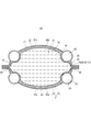
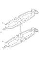
 図8では、外側フィルム層22及び内側フィルム層23の各々において、相互に接合されて本体シール部26となる領域には、便宜的に右上がりのハッチングを付している。
 図9及び図10では、本体構成シート材21において、非接合部24を画定するために外側フィルム層22と内側フィルム層23とが相互に接合されている領域、すなわち本体シール部26の形成領域には、便宜的に右上がりのハッチングを付している。
 更に、図9では、本体構成シート材21の周縁部のシール領域と、それ以外の領域と、の境界線であるシール境界線21cを二点鎖線で示している。本実施形態の場合、本体構成シート材21のシール境界線21cよりも外側の領域においては、製袋の際に、外側フィルム層22と内側フィルム層23とが相互に接合されるとともに、内側フィルム層23と内袋構成シート材41とが相互に接合される。
 外側フィルム層22と内側フィルム層23との接合の手法としては、一例として、ヒートシール、超音波シール、接着剤による接合等を用いることができる。
The main body constituent sheet material 21 is formed with a non-bonded portion 24 (FIG. 9) in which the outer film layer 22 and the inner film layer 23 are partially non-bonded. For example, in one or both of the outer film layer 22 and the inner film layer 23, the surface facing the other is partially non-bonded. The non-bonding treatment can be easily formed by applying a non-bonding agent (so-called glue-killing agent) to bring it into a glue-killing state. As the glue killing agent, any agent can be used as long as it can suppress the bonding between the outer film layer 22 and the inner film layer 23. As the glue-killing agent, for example, printing inks, medium inks, glue-killing inks and the like used for each of offset printing, flexographic printing and letter press printing (letterpress printing) can be preferably used. Further, a thermosetting type ink or an ultraviolet curable type ink can be preferably used. The area where the non-joining treatment is applied is the non-joining portion 24. The filling portion 60 is formed by sealing the filler in the non-joining portion 24.
The filling portion 60 is not necessarily formed on all of the non-joining portions 24, and may be formed on a part of a plurality of non-joining portions 24.
In FIG. 8, in each of the outer film layer 22 and the inner film layer 23, a hatching that rises to the right is provided for convenience in the region that is joined to each other to form the main body sealing portion 26.
In FIGS. 9 and 10, in the main body constituent sheet material 21, a region in which the outer film layer 22 and the inner film layer 23 are joined to each other in order to define the non-bonded portion 24, that is, a region where the main body seal portion 26 is formed. Has a hatching that rises to the right for convenience.
Further, in FIG. 9, the seal boundary line 21c, which is the boundary line between the seal region of the peripheral portion of the main body constituent sheet material 21 and the other region, is shown by a two-dot chain line. In the case of the present embodiment, in the region outside the seal boundary line 21c of the main body constituent sheet material 21, the outer film layer 22 and the inner film layer 23 are joined to each other at the time of bag making, and the inner film is formed. The layer 23 and the inner bag constituent sheet material 41 are joined to each other.
As a method of joining the outer film layer 22 and the inner film layer 23, as an example, heat sealing, ultrasonic sealing, bonding with an adhesive, or the like can be used.
 本実施形態の場合、外側フィルム層22及び内側フィルム層23の各々は、複数の樹脂層を含む層構造をなしている。また、内袋構成シート材41も、複数の樹脂層を含む層構造をなしている。 In the case of the present embodiment, each of the outer film layer 22 and the inner film layer 23 has a layer structure including a plurality of resin layers. Further, the inner bag constituent sheet material 41 also has a layer structure including a plurality of resin layers.
 本体構成シート材21は、ポリエチレン系、ポリプロピレン系、ポリエステル系又はポリアミド系のいずれか1種の樹脂層を含んでいることが好ましい。
 本体構成シート材21の外側フィルム層22及び内側フィルム層23を構成する樹脂層の材料は、特に限定されないが、例えば、高密度ポリエチレン(HDPE)、中密度ポリエチレン(MDPE)、低密度ポリエチレン(LDPE)、直鎖状低密度ポリエチレン(LLDPE)、超低密度ポリエチレン(ULDPE)、エチレン-ビニルアルコール共重合体(EVOH)などのポリエチレン系材料、または延伸ポリプロピレン(OPP)、未延伸ポリプロピレン(CPP)、アイソタクチックPP、シンジオタクチックPP、アタクチックPP、ランダムPP、ブロックPPなどのポリプロピレン系材料、またはポリエチレンテレフタレート(PET)、非晶性ポリエチレンテレフタレート(非晶性PET)、ポリブチレンテレフタレート(PBT)、ポリエチレンナフタレート(PEN)、ポリブチレンナフタレート(PBN)などのポリエステル系材料、または延伸ナイロン(ONy)、未延伸ナイロン(CNy)、ナイロン6、ナイロン66、ナイロン11、ナイロン12、MXD6などのポリアミド系材料のいずれかであるのがより好ましく、これらのうち上記ポリエチレン系材料であるのが特に好ましい。
The main body constituent sheet material 21 preferably contains any one of a polyethylene-based, polypropylene-based, polyester-based, and polyamide-based resin layers.
The material of the resin layer constituting the outer film layer 22 and the inner film layer 23 of the main body constituent sheet material 21 is not particularly limited, and is, for example, high-density polyethylene (HDPE), medium-density polyethylene (MDPE), and low-density polyethylene (LDPE). ), Linear low density polyethylene (LLDPE), ultra low density polyethylene (ULDPE), polyethylene-based materials such as ethylene-vinyl alcohol copolymer (EVOH), or stretched polypropylene (OPP), unstretched polypropylene (CPP), Polypropylene-based materials such as isotactic PP, syndiotactic PP, atactic PP, random PP, block PP, or polyethylene terephthalate (PET), amorphous polyethylene terephthalate (acrystalline PET), polybutylene terephthalate (PBT), Polyethylene-based materials such as polyethylene naphthalate (PEN) and polybutylene naphthalate (PBN), or polyamides such as stretched nylon (ONy), unstretched nylon (CNy), nylon 6, nylon 66, nylon 11, nylon 12, MXD6, etc. It is more preferably one of the based materials, and among these, the polyethylene-based material is particularly preferable.
 外側フィルム層22は、一例として、第1層、第2層、第3層及び第4層の4つの樹脂層をこの順に積層することにより構成された4層構造をなしている。
 このうち第1層は、容器本体20の外面を構成する。第1層は、例えば、ポリエチレンテレフタレート(PET)または延伸ナイロン(ONy)により構成されている。第1層の主な機能としては、容器本体20に光沢感及び印刷適性をもたらすとともに容器本体20の剛性を確保することが挙げられる。
 第2層は、例えば、当該第2層における第1層側の面にシリカ及び/又はアルミナが蒸着されたポリエチレンテレフタレートにより構成された透明蒸着PETの層である。第2層の主な機能としては、容器本体20にガスバリア性をもたらすことが挙げられる。
 第3層は、例えば、延伸ナイロンにより構成されている。第3層の主な機能としては、容器本体20の耐ピンホール性を確保することが挙げられる。
 第4層は、例えば、直鎖状低密度ポリエチレン(LLDPE)により構成されている。第4層の主な機能としては、内側フィルム層23とのヒートシール性を確保することが挙げられる。
As an example, the outer film layer 22 has a four-layer structure formed by laminating four resin layers of the first layer, the second layer, the third layer, and the fourth layer in this order.
Of these, the first layer constitutes the outer surface of the container body 20. The first layer is made of, for example, polyethylene terephthalate (PET) or stretched nylon (ONy). The main function of the first layer is to provide the container body 20 with a glossy feeling and printability, and to secure the rigidity of the container body 20.
The second layer is, for example, a layer of transparent vapor-deposited PET composed of polyethylene terephthalate in which silica and / or alumina is vapor-deposited on the surface of the second layer on the first-layer side. The main function of the second layer is to provide the container body 20 with a gas barrier property.
The third layer is made of, for example, stretched nylon. The main function of the third layer is to secure pinhole resistance of the container body 20.
The fourth layer is made of, for example, linear low density polyethylene (LLDPE). The main function of the fourth layer is to secure heat sealability with the inner film layer 23.
 内側フィルム層23の層構造としては、外側フィルム層22の第1層から第4層と同様の層構造に加えて、例えば直鎖状低密度ポリエチレン(LLDPE)により構成されている第5層を備える構造が挙げられる。第5層は、第1層と隣接した層であり、内側フィルム層23における第4層とは反対側の面を構成している。第5層の主な機能としては、外側フィルム層22とのヒートシール性を確保することが挙げられる。
 内側フィルム層23の第4層の主な機能としては、内袋構成シート材41とのヒートシール性を確保することが挙げられる。
 ただし、外側フィルム層22及び内側フィルム層23の層構造は、上記の例に限らず、また、外側フィルム層22及び内側フィルム層23を構成する各層の材料は、上記の例に限らない。
As the layer structure of the inner film layer 23, in addition to the same layer structure as the first to fourth layers of the outer film layer 22, for example, a fifth layer composed of linear low density polyethylene (LLDPE) is used. The structure to be provided can be mentioned. The fifth layer is a layer adjacent to the first layer, and constitutes a surface of the inner film layer 23 opposite to the fourth layer. The main function of the fifth layer is to secure heat sealability with the outer film layer 22.
The main function of the fourth layer of the inner film layer 23 is to secure the heat sealability with the inner bag constituent sheet material 41.
However, the layer structure of the outer film layer 22 and the inner film layer 23 is not limited to the above example, and the material of each layer constituting the outer film layer 22 and the inner film layer 23 is not limited to the above example.
 内袋40を構成する内袋構成シート材41は、一例として、第1層、第2層及び第3層をこの順に積層することにより構成された3層構造をなしている。
 このうち第1層は、例えば、直鎖状低密度ポリエチレンにより構成されている。第1層の主な機能としては、本体構成シート材21とのヒートシール性(内側フィルム層23とのヒートシール性)を確保することが挙げられる。
 第2層は、例えば、当該第2層における第1層側の面にシリカ及び/又はアルミナが蒸着された延伸ナイロンにより構成された透明蒸着延伸ナイロンの層である。第2層の主な機能としては、ガスバリア性及び耐ピンホール性を確保することが挙げられる。
 第3層は、例えば、直鎖状低密度ポリエチレンにより構成されている。第3層の主な機能としては、内袋構成シート材41どうしのヒートシール性を確保することが挙げられる。
 なお、内袋構成シート材41の層構造は、ここで説明した構造に限らない。
As an example, the inner bag constituent sheet material 41 constituting the inner bag 40 has a three-layer structure formed by laminating the first layer, the second layer, and the third layer in this order.
Of these, the first layer is made of, for example, linear low-density polyethylene. The main function of the first layer is to secure heat-sealing property with the main body constituent sheet material 21 (heat-sealing property with the inner film layer 23).
The second layer is, for example, a layer of transparent vapor-deposited stretched nylon composed of stretched nylon in which silica and / or alumina is vapor-deposited on the surface of the second layer on the first layer side. The main function of the second layer is to secure gas barrier properties and pinhole resistance.
The third layer is made of, for example, linear low density polyethylene. The main function of the third layer is to secure the heat sealability between the inner bag constituent sheet materials 41.
The layer structure of the inner bag constituent sheet material 41 is not limited to the structure described here.
 図9及び図10に示すように本体構成シート材21に内袋構成シート材41が積層され、図10に示すように内側フィルム層23の周縁部と内袋構成シート材41の周縁部とが相互に接合されるとともに、外側フィルム層22の周縁部と内側フィルム層23の周縁部とが相互に接合されている。これにより、本体構成シート材21と内袋構成シート材41とにより容器構成シート材51が構成されている。
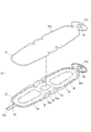
 ここで、容器構成シート材51の周縁部のシール部を周縁シール部52と称する。周縁シール部52は、内側フィルム層23の周縁部と内袋構成シート材41の周縁部とのシール部(以下、内外シール部43)と、外側フィルム層22の周縁部と内側フィルム層23の周縁部とのシール部(以下、本体周縁シール部28)と、を含む。
 図10において、周縁シール部52の形成領域には、左上がりのハッチングを付している。また、図10において、周縁シール部52の形成領域と本体シール部26の形成領域とが重複している領域では、左上がりのハッチングと右上がりのハッチングとが重なっている。
 周縁シール部52を形成する手法としては、一例として、ヒートシール、超音波シール、接着剤による接合等を用いることができる。
As shown in FIGS. 9 and 10, the inner bag constituent sheet material 41 is laminated on the main body constituent sheet material 21, and as shown in FIG. 10, the peripheral edge portion of the inner film layer 23 and the peripheral edge portion of the inner bag constituent sheet material 41 are formed. In addition to being bonded to each other, the peripheral edge of the outer film layer 22 and the peripheral edge of the inner film layer 23 are bonded to each other. As a result, the container constituent sheet material 51 is composed of the main body constituent sheet material 21 and the inner bag constituent sheet material 41.
Here, the sealing portion of the peripheral edge portion of the container constituent sheet material 51 is referred to as a peripheral edge sealing portion 52. The peripheral edge sealing portion 52 is a sealing portion between the peripheral edge portion of the inner film layer 23 and the peripheral edge portion of the inner bag constituent sheet material 41 (hereinafter, inner / outer sealing portion 43), and the peripheral edge portion of the outer film layer 22 and the inner film layer 23. Includes a sealing portion with the peripheral edge portion (hereinafter, main body peripheral edge sealing portion 28).
In FIG. 10, a hatching that rises to the left is provided in the forming region of the peripheral seal portion 52. Further, in FIG. 10, in the region where the forming region of the peripheral seal portion 52 and the forming region of the main body sealing portion 26 overlap, the hatching that rises to the left and the hatching that rises to the right overlap.
As a method for forming the peripheral seal portion 52, as an example, heat seal, ultrasonic seal, bonding with an adhesive, or the like can be used.
 図10に示すように、本体構成シート材21は、例えば、第1主面部20aを構成する部分である第1シート部31と、第2主面部20bを構成する部分である第2シート部32と、底マチ13を構成する部分である底マチ構成シート部38と、天マチ14を構成する部分である天マチ構成シート部39と、チューブ状の延出部25と、を有する。延出部25は、例えば、第2シート部32から外方に延出している。
 天マチ構成シート部39には、スパウト部材15の注出筒部15aが挿通される挿通穴21aが形成されている。
 本実施形態の場合、非接合部24は、シート材容器100の充填部60の形状と対応する形状に形成されている。
As shown in FIG. 10, the main body constituent sheet material 21 is, for example, a first sheet portion 31 which is a portion constituting the first main surface portion 20a and a second sheet portion 32 which is a portion constituting the second main surface portion 20b. It also has a bottom gusset constituent sheet portion 38 which is a portion constituting the bottom gusset 13, a heavenly gusset constituent sheet portion 39 which is a portion constituting the heavenly gusset 14, and a tubular extending portion 25. The extending portion 25 extends outward from, for example, the second sheet portion 32.
The top gusset constituent sheet portion 39 is formed with an insertion hole 21a into which the ejection cylinder portion 15a of the spout member 15 is inserted.
In the case of the present embodiment, the non-joining portion 24 is formed in a shape corresponding to the shape of the filling portion 60 of the sheet material container 100.
 非接合部24において、第4充填部64となる部分24bは、例えば、図10に示すように、挿通穴21aを囲む周回状に形成されている。より詳細には、例えば、部分24bの外縁(外形線)は、天マチ構成シート部39の外形線よりも一回り小さい形状となっており、部分24bの内縁は、挿通穴21aよりも一回り大きい円形となっている。 In the non-joined portion 24, the portion 24b to be the fourth filling portion 64 is formed in a circumferential shape surrounding the insertion hole 21a, for example, as shown in FIG. More specifically, for example, the outer edge (outer line) of the portion 24b has a shape that is one size smaller than the outer line of the top gusset constituent sheet portion 39, and the inner edge of the portion 24b is one size smaller than the insertion hole 21a. It is a large circle.
 本実施形態の場合、内袋構成シート材41は、本体構成シート材21における延出部25を除く部分と同形状に形成されている。
 なお、図9では、内袋構成シート材41のシール境界線41aを便宜的に二点鎖線で示している。シール境界線41aは、内袋構成シート材41が本体構成シート材21と接合(シール)される領域と内袋構成シート材41における他の領域との境界線であるとともに、容器構成シート材51を用いてシート材容器100が形成される際に内袋構成シート材41どうしが接合される領域と内袋構成シート材41における他の領域との境界線である。
 本実施形態の場合、シール境界線41aの位置とシール境界線21cの位置とは互いに対応している(互いに重なっている)。
In the case of the present embodiment, the inner bag constituent sheet material 41 is formed in the same shape as the portion of the main body constituent sheet material 21 excluding the extending portion 25.
In FIG. 9, the seal boundary line 41a of the inner bag constituent sheet material 41 is shown by a two-dot chain line for convenience. The seal boundary line 41a is a boundary line between a region where the inner bag constituent sheet material 41 is joined (sealed) with the main body constituent sheet material 21 and another region in the inner bag constituent sheet material 41, and the container constituent sheet material 51. It is a boundary line between the region where the inner bag constituent sheet materials 41 are joined to each other when the sheet material container 100 is formed using the above, and another region in the inner bag constituent sheet material 41.
In the case of the present embodiment, the position of the seal boundary line 41a and the position of the seal boundary line 21c correspond to each other (overlap each other).
 内袋構成シート材41において天マチ構成シート部39と重なる部分には、スパウト部材15の注出筒部15aが挿通される挿通穴41bが形成されている。
 スパウト部材15の板状部15bは、例えば、内袋構成シート材41において天マチ構成シート部39と重なっている部分の内面に対して接合されている。注出筒部15aは、内袋構成シート材41の挿通穴41b及び天マチ構成シート部39の挿通穴21aを通してこれらシートの外面側に突出している。
An insertion hole 41b through which the ejection cylinder portion 15a of the spout member 15 is inserted is formed in a portion of the inner bag constituent sheet material 41 that overlaps with the top gusset constituent sheet portion 39.
The plate-shaped portion 15b of the spout member 15 is joined to, for example, the inner surface of the portion of the inner bag constituent sheet material 41 that overlaps with the top gusset constituent sheet portion 39. The injection cylinder portion 15a projects toward the outer surface side of the inner bag constituent sheet material 41 through the insertion hole 41b and the top gusset constituent sheet portion 39 through the insertion hole 21a.
 容器構成シート材51が、図10に示す折り曲げ線81、折り曲げ線82及び折り曲げ線84においてそれぞれ谷折りされるとともに、折り曲げ線83及び折り曲げ線85においてそれぞれ山折りされた状態で、容器構成シート材51の周縁部どうし(内袋構成シート材41どうし)が接合されることによって、容器構成シート材51が二重構造の袋状に形成される。ここで、谷折りとは、図10における奥側に向けて凸の折り曲げ方であり、山折りとは、図10における手前側に向けて凸の折り曲げ方である。
 すなわち、内袋構成シート材41の縁部どうしが接合されて内袋シール部42(図1参照)が形成されることにより、内袋構成シート材41によって内袋40が形成されるとともに、内袋40を覆う袋状の容器本体20が形成される。
 内袋構成シート材41どうしの接合の手法としては、一例として、ヒートシール、超音波シール、接着剤による接合等を用いることができる。
 本実施形態の場合、本体周縁シール部28、内袋シール部42及び内外シール部43は、互いに対応する位置(互いに重なる位置)に配置されている。本体周縁シール部28、内袋シール部42及び内外シール部43の総称を周縁シール部19とする(周縁シール部19は、本体周縁シール部28、内袋シール部42及び内外シール部43を含む)。
 このため、本実施形態の場合、マチ部周縁シール片45並びに側部シール片46の各々は、本体周縁シール部28、内袋シール部42及び内外シール部43を含んで構成されている。
 ただし、本発明は、この例に限らず、マチ部周縁シール片45並びに側部シール片46は、本体周縁シール部28のみにより構成されていてもよい。
The container constituent sheet material 51 is valley-folded at the fold line 81, the fold line 82, and the fold line 84 shown in FIG. 10, and is mountain-folded at the fold line 83 and the fold line 85, respectively. By joining the peripheral edges of 51 (inner bag constituent sheet materials 41 to each other), the container constituent sheet material 51 is formed in a double-structured bag shape. Here, the valley fold is a folding method that is convex toward the back side in FIG. 10, and the mountain fold is a folding method that is convex toward the front side in FIG.
That is, the edges of the inner bag constituent sheet material 41 are joined to each other to form the inner bag sealing portion 42 (see FIG. 1), whereby the inner bag 40 is formed by the inner bag constituent sheet material 41 and the inner bag 40 is formed. A bag-shaped container body 20 that covers the bag 40 is formed.
As a method of joining the inner bag constituent sheet materials 41 to each other, as an example, heat sealing, ultrasonic sealing, joining with an adhesive or the like can be used.
In the case of the present embodiment, the main body peripheral edge seal portion 28, the inner bag seal portion 42, and the inner / outer seal portion 43 are arranged at positions corresponding to each other (positions overlapping each other). The peripheral seal portion 28, the inner bag seal portion 42, and the inner / outer seal portion 43 are collectively referred to as the peripheral seal portion 19 (the peripheral seal portion 19 includes the main body peripheral seal portion 28, the inner bag seal portion 42, and the inner / outer seal portion 43. ).
Therefore, in the case of the present embodiment, each of the gusset peripheral peripheral seal piece 45 and the side seal piece 46 includes the main body peripheral seal portion 28, the inner bag seal portion 42, and the inner / outer seal portion 43.
However, the present invention is not limited to this example, and the gusset peripheral peripheral seal piece 45 and the side seal piece 46 may be composed of only the main body peripheral seal portion 28.
 第1シート部31において、折り曲げ線85よりも天マチ構成シート部39側の部分は、第1重複部31aである。第1重複部31aは、非接合部24に充填材が充填される前の状態では、天マチ構成シート部39における一方の半部と重なって配置されている。
 第2シート部32において、折り曲げ線86よりも底マチ構成シート部38から遠い側に位置する部分は、第2重複部32aである。第2重複部32aは、非接合部24に充填材が充填される前の状態では、天マチ構成シート部39における他方の半部と重なって配置されている。
In the first sheet portion 31, the portion of the top gusset constituent sheet portion 39 side of the bending line 85 is the first overlapping portion 31a. The first overlapping portion 31a is arranged so as to overlap one half of the top gusset constituent sheet portion 39 in a state before the non-joining portion 24 is filled with the filler.
In the second sheet portion 32, the portion located on the side farther from the bottom gusset constituent sheet portion 38 than the bending line 86 is the second overlapping portion 32a. The second overlapping portion 32a is arranged so as to overlap the other half portion of the top gusset constituent sheet portion 39 in a state before the non-joining portion 24 is filled with the filler.
 こうして、図12に示すように、容器構成シート材51が二重の袋状に形成され、シート材容器100が得られる。シート材容器100は、例えば、延出部25に形成されている注入口25a(図10)から非接合部24に充填材が注入され、その後、延出部25の基端側に連接する部位において非接合部24が封止される。これにより、非接合部24(充填部60)に充填材が封入される。
 なお、充填部60の内部における圧力は、特に限定されないが、大気圧よりも高圧であることが好ましく、例えば、10kPa以上500kPa以下(ゲージ圧)とすることができる。
 すなわち、充填材を封入可能な充填部とは、外側フィルム層22と内側フィルム層23との層間に位置し、10kPa以上500kPa以下程度の圧力で充填材が封入されたときに密閉性を保持することが可能な空間をいう。
 充填材が封入された充填部60の形成後、例えば、延出部25は切除される。
 こうして、充填部60に充填材が封入されたシート材容器100(図1~図7参照)が得られる。ただし、充填材が封入されたシート材容器100の状態でも延出部25が残留していてもよい。
In this way, as shown in FIG. 12, the container constituent sheet material 51 is formed in a double bag shape, and the sheet material container 100 is obtained. In the sheet material container 100, for example, a portion where the filler is injected into the non-joining portion 24 from the injection port 25a (FIG. 10) formed in the extending portion 25 and then connected to the proximal end side of the extending portion 25. The non-joint portion 24 is sealed at. As a result, the filler is sealed in the non-joining portion 24 (filling portion 60).
The pressure inside the filling portion 60 is not particularly limited, but is preferably higher than the atmospheric pressure, and can be, for example, 10 kPa or more and 500 kPa or less (gauge pressure).
That is, the filling portion in which the filler can be sealed is located between the outer film layer 22 and the inner film layer 23, and maintains the airtightness when the filler is sealed at a pressure of about 10 kPa or more and 500 kPa or less. A space where it is possible.
After forming the filling portion 60 in which the filler is sealed, for example, the extending portion 25 is cut off.
In this way, the sheet material container 100 (see FIGS. 1 to 7) in which the filler is sealed in the filling portion 60 is obtained. However, the extending portion 25 may remain even in the state of the sheet material container 100 in which the filler is sealed.
 シート材容器100の作製後、スパウト部材15の注出筒部15aを通して収容領域17に内容物18を充填した後で、スパウト部材15にキャップ部70が装着されることによって、収容領域17に内容物18が封入されたシート材容器100が得られる。 After the sheet material container 100 is manufactured, the content 18 is filled in the accommodating area 17 through the pouring cylinder portion 15a of the spout member 15, and then the cap portion 70 is attached to the spout member 15 to fill the accommodating area 17. A sheet material container 100 in which the object 18 is enclosed is obtained.
 図11は、図10の部分拡大図であり、第1主面部20aとなる第1シート部31と、天マチ14となる天マチ構成シート部39と、の境界およびその近傍の部分を示している。
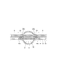
 本実施形態の場合、外側フィルム層22、内側フィルム層23及び内袋構成シート材41は、互いに同形状であり、互いの外形線が一致するように積層されている。
 このため、図11に示すように、第1主面部20aとなる第1シート部31と天マチ14となる天マチ構成シート部39との境界において、外側フィルム層22の外縁22a、内側フィルム層23の外縁23a、及び、内袋構成シート材41の外縁41cが、互いに一致している。また、第1シート部31と底マチ13となる底マチ構成シート部38との境界においても、外側フィルム層22の外縁22a、内側フィルム層23の外縁23a、及び、内袋構成シート材41の外縁41cが、互いに一致している。同様に、第2主面部20bとなる第2シート部32と底マチ構成シート部38との境界においても、外側フィルム層22の外縁22a、内側フィルム層23の外縁23a、及び、内袋構成シート材41の外縁41cが、互いに一致している。
 そして、容器構成シート材51がシート材容器100となった後の状態においても、第1主面部20aと天マチ14との境界、第1主面部20aと底マチ13との境界、及び、第2主面部20bと底マチ13との境界において、外側フィルム層22の外縁22a、内側フィルム層23の外縁23a、及び、内袋構成シート材41の外縁41cが、互いに一致している。
FIG. 11 is a partially enlarged view of FIG. 10, showing a boundary between the first sheet portion 31 serving as the first main surface portion 20a and the heavenly gusset constituent sheet portion 39 serving as the heavenly gusset 14 and a portion in the vicinity thereof. There is.
In the case of the present embodiment, the outer film layer 22, the inner film layer 23, and the inner bag constituent sheet material 41 have the same shape and are laminated so that their outer lines coincide with each other.
Therefore, as shown in FIG. 11, at the boundary between the first sheet portion 31 serving as the first main surface portion 20a and the ceiling gusset constituent sheet portion 39 serving as the ceiling gusset 14, the outer edge 22a of the outer film layer 22 and the inner film layer The outer edge 23a of the 23 and the outer edge 41c of the inner bag constituent sheet material 41 coincide with each other. Further, at the boundary between the first sheet portion 31 and the bottom gusset constituent sheet portion 38 serving as the bottom gusset 13, the outer edge 22a of the outer film layer 22, the outer edge 23a of the inner film layer 23, and the inner bag constituent sheet material 41 The outer edges 41c coincide with each other. Similarly, at the boundary between the second sheet portion 32 serving as the second main surface portion 20b and the bottom gusset constituent sheet portion 38, the outer edge 22a of the outer film layer 22, the outer edge 23a of the inner film layer 23, and the inner bag constituent sheet are also formed. The outer edges 41c of the material 41 coincide with each other.
Then, even in the state after the container constituent sheet material 51 becomes the sheet material container 100, the boundary between the first main surface portion 20a and the heaven gusset 14, the boundary between the first main surface portion 20a and the bottom gusset 13, and the first At the boundary between the two main surface portions 20b and the bottom gusset 13, the outer edge 22a of the outer film layer 22, the outer edge 23a of the inner film layer 23, and the outer edge 41c of the inner bag constituent sheet material 41 coincide with each other.
 図11には、製袋後に周縁シール部19となる領域に、周縁シール部19の符号を付している。
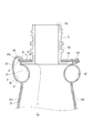
 図11に示すように、本実施形態の場合、第1主面部20aと天マチ14との境界において、本体構成シート材21が折り曲げ線84に沿って折り曲げられるとともに、第1主面部20aの周縁部と天マチ14の周縁部とが周縁シール部19によって相互に接合されている。周縁シール部19においては、シート材容器100を構成する全てのフィルム層が接合されている。すなわち、本実施形態において、図7に示すように、周縁シール部19においては、第1主面部20aにおける内袋構成シート材41、内側フィルム層23、外側フィルム層22および天マチ14における内袋構成シート材41、内側フィルム層23、外側フィルム層22の計6層が接合されている。
 図7、図11に示すように、折り曲げ線84に沿った周縁シール部19の端部19aが、面間接続部65と本体シール部26との境界位置26aから離間している。このため、第1面状部と第2面状部との境界では、面間接続部65よりも外側の領域(周縁シール部19の端部19aから面間接続部65と本体シール部26との境界位置26aまでの領域)においても、シート材容器100を構成するフィルム層どうし(本実施形態においては、内袋構成シート材41どうし、および内袋構成シート材41と内側フィルム層23)が剥離している構造となっている。本実施形態においては、周縁シール部19は上述したとおり6層のシート材が接合しているため高い剛性を有しているところ、第1面状部と第2面状部との境界において、周縁シール部19の端部19aが面間接続部65から離間しているため、面間接続部65(非接合部24)を構成する外側フィルム層22と内側フィルム層23の動きが規制されにくく、外側フィルム層22と内側フィルム層23との層間の間隙(非接合部24の間隙)を確保しやすくなる。このため、折り曲げ線84に沿って折り曲げられた状態で、充填部に充填材を充填する際に、第1面状部の充填部60と第2面状部の充填部60との間で容易に充填材が流通可能となり、例えば、第1面状部の充填部60から面間接続部65を介して第2面状部の充填部60へと充填材を容易に充填することができる。
 また、第1面状部と第2面状部との境界において、周縁シール部19に対して本体シール部26が隣接している。すなわち、周縁シール部19と本体シール部26との間に非接合部24が存在していない。このため、充填部60に充填材を封入した状態において、非接合部24に応力が集中し、シート材が破けるといった不具合を抑制することができる。
 また、第1主面部20aと天マチ14との境界において、折り曲げ線84に沿った周縁シール部19の幅寸法W1が本体シール部26の幅寸法W2以上であり、好ましくは、幅寸法W1が幅寸法W2よりも大きい。幅寸法W1は、周縁シール部19のうち、本体構成シート材21の折り曲げ線84において、第1主面部20a(第1面状部)と天マチ14(第2面状部)とが繋がっている領域の幅を指す。
 幅寸法W1が幅寸法W2以上であることによって、容器本体20の周縁部の剛性を十分に確保することができる。また、幅寸法W1が幅寸法W2以上であることによって、第1主面部20aと天マチ14との境界の輪郭が明確になるため、第1主面部と第2主面部との外観の差ができにくくなり、シート材容器100の外観を良好に保つことができる。
In FIG. 11, a reference numeral of the peripheral seal portion 19 is attached to a region that becomes the peripheral seal portion 19 after bag making.
As shown in FIG. 11, in the case of the present embodiment, at the boundary between the first main surface portion 20a and the heaven gusset 14, the main body constituent sheet material 21 is bent along the bending line 84, and the peripheral edge of the first main surface portion 20a is formed. The portion and the peripheral edge portion of the heaven gusset 14 are joined to each other by the peripheral edge sealing portion 19. In the peripheral seal portion 19, all the film layers constituting the sheet material container 100 are joined. That is, in the present embodiment, as shown in FIG. 7, in the peripheral seal portion 19, the inner bag constituent sheet material 41 in the first main surface portion 20a, the inner film layer 23, the outer film layer 22, and the inner bag in the top gusset 14 A total of 6 layers, that is, the constituent sheet material 41, the inner film layer 23, and the outer film layer 22 are joined.
As shown in FIGS. 7 and 11, the end portion 19a of the peripheral edge sealing portion 19 along the bending line 84 is separated from the boundary position 26a between the face-to-face connecting portion 65 and the main body sealing portion 26. Therefore, at the boundary between the first surface-like portion and the second surface-like portion, the region outside the face-to-face connection portion 65 (from the end portion 19a of the peripheral edge seal portion 19 to the face-to-face connection portion 65 and the main body seal portion 26). Even in the region up to the boundary position 26a), the film layers constituting the sheet material container 100 (in the present embodiment, the inner bag constituent sheet materials 41 and the inner bag constituent sheet material 41 and the inner film layer 23) are separated from each other. It has a peeling structure. In the present embodiment, the peripheral edge sealing portion 19 has high rigidity because the six layers of sheet materials are joined as described above, but at the boundary between the first planar portion and the second planar portion, the peripheral sealing portion 19 has high rigidity. Since the end portion 19a of the peripheral edge sealing portion 19 is separated from the face-to-face connecting portion 65, the movements of the outer film layer 22 and the inner film layer 23 constituting the face-to-face connecting portion 65 (non-joining portion 24) are less likely to be restricted. , It becomes easy to secure the gap between the outer film layer 22 and the inner film layer 23 (the gap between the non-bonded portions 24). Therefore, when filling the filling portion with the filler in a state of being bent along the bending line 84, it is easy to fill the filling portion between the filling portion 60 of the first planar portion and the filling portion 60 of the second planar portion. The filler can be circulated to the surface, and for example, the filler can be easily filled from the filling portion 60 of the first planar portion to the filling portion 60 of the second planar portion via the inter-plane connecting portion 65.
Further, at the boundary between the first planar portion and the second planar portion, the main body sealing portion 26 is adjacent to the peripheral sealing portion 19. That is, the non-joining portion 24 does not exist between the peripheral edge sealing portion 19 and the main body sealing portion 26. Therefore, in a state where the filler is sealed in the filled portion 60, it is possible to suppress a problem that stress is concentrated on the non-joined portion 24 and the sheet material is torn.
Further, at the boundary between the first main surface portion 20a and the top gusset 14, the width dimension W1 of the peripheral edge sealing portion 19 along the bending line 84 is equal to or greater than the width dimension W2 of the main body sealing portion 26, preferably the width dimension W1. It is larger than the width dimension W2. The width dimension W1 is such that the first main surface portion 20a (first surface-like portion) and the top gusset 14 (second surface-like portion) are connected at the bending line 84 of the main body constituent sheet material 21 in the peripheral seal portion 19. Refers to the width of the area.
When the width dimension W1 is equal to or larger than the width dimension W2, the rigidity of the peripheral portion of the container body 20 can be sufficiently ensured. Further, when the width dimension W1 is equal to or larger than the width dimension W2, the outline of the boundary between the first main surface portion 20a and the heavenly gusset 14 becomes clear, so that the difference in appearance between the first main surface portion and the second main surface portion is large. It becomes difficult to make it, and the appearance of the sheet material container 100 can be kept good.
 また、第1主面部20aと天マチ14との境界において、折り曲げ線84に沿った周縁シール部19の幅寸法W1と本体シール部26の幅寸法W2との合計値が、面間接続部65(非接合部24)の幅寸法W3の半分よりも大きい。換言すれば、幅寸法W3が、幅寸法W1と幅寸法W2との合計値の2倍よりも小さい。これにより、面間接続部65を細くすることができるため、第1主面部20aと天マチ14との境界の見栄えを良好にすることができる。ここで、面間接続部65の幅寸法W3は、充填材を封入していない状態における寸法を指す。 Further, at the boundary between the first main surface portion 20a and the gusset 14, the total value of the width dimension W1 of the peripheral edge seal portion 19 along the bending line 84 and the width dimension W2 of the main body seal portion 26 is the face-to-face connection portion 65. It is larger than half of the width dimension W3 of (non-joint portion 24). In other words, the width dimension W3 is smaller than twice the total value of the width dimension W1 and the width dimension W2. As a result, the face-to-face connection portion 65 can be made thinner, so that the appearance of the boundary between the first main surface portion 20a and the heavenly gusset 14 can be improved. Here, the width dimension W3 of the face-to-face connection portion 65 refers to a dimension in a state where the filler is not sealed.
 また、シート材の厚み方向から見て面間接続部65の存在する位置において、シート材容器100を構成するフィルム層どうしがすべて非接合となっている。つまり、面間接続部65においては、図7に示すように、外側フィルム層22の一部分、内側フィルム層23の一部分、内袋構成シート材41の一部分、内袋構成シート材41の他の一部分、内側フィルム層23の他の一部分、及び、外側フィルム層22の他の一部分が、この順に積層されているが、これらがすべて非接合となっている。これにより、非接合部24における各フィルム層どうしのある程度自由に相対的に移動できるため、第1面状部と第2面状部との境界において、外側フィルム層22と内側フィルム層23との層間の間隙(非接合部24の間隙)をより確実に確保しやすくなる。 Further, at the position where the inter-plane connection portion 65 is present when viewed from the thickness direction of the sheet material, all the film layers constituting the sheet material container 100 are non-bonded. That is, in the face-to-face connection portion 65, as shown in FIG. 7, a part of the outer film layer 22, a part of the inner film layer 23, a part of the inner bag constituent sheet material 41, and another part of the inner bag constituent sheet material 41. , The other part of the inner film layer 23 and the other part of the outer film layer 22 are laminated in this order, but they are all non-bonded. As a result, the film layers in the non-bonded portion 24 can move relatively freely to some extent, so that the outer film layer 22 and the inner film layer 23 are separated from each other at the boundary between the first planar portion and the second planar portion. It becomes easier to secure the gap between the layers (the gap between the non-joining portions 24) more reliably.
 次に、図18から図22を用いて変形例を説明する。 Next, a modified example will be described with reference to FIGS. 18 to 22.
 <変形例1>
 上記の第1実施形態では、第1面状部と第2面状部との境界において、周縁シール部19に対して本体シール部26が隣接している例を説明した。これに対し、図18に示す変形例1の場合、第1面状部と第2面状部との境界において、周縁シール部19と本体シール部26との間には、各フィルム層どうしが非接合となっている非シール部111が介在している。非シール部111においては、外側フィルム層22と内側フィルム層23とが非接合となっているとともに、内側フィルム層23と内袋構成シート材41とが非接合となっている。すなわち、非シール部111においては、外側フィルム層22の一部分、内側フィルム層23の一部分、内袋構成シート材41の一部分、内袋構成シート材41の他の一部分、内側フィルム層23の他の一部分、及び、外側フィルム層22の他の一部分が、互いに非接合の状態で、この順に積層されている。
<Modification example 1>
In the above-described first embodiment, an example in which the main body seal portion 26 is adjacent to the peripheral seal portion 19 at the boundary between the first planar portion and the second planar portion has been described. On the other hand, in the case of the modified example 1 shown in FIG. 18, at the boundary between the first surface-shaped portion and the second surface-shaped portion, the film layers are formed between the peripheral edge sealing portion 19 and the main body sealing portion 26. A non-sealed portion 111 that is not joined is interposed. In the non-sealing portion 111, the outer film layer 22 and the inner film layer 23 are not joined, and the inner film layer 23 and the inner bag constituent sheet material 41 are not joined. That is, in the non-seal portion 111, a part of the outer film layer 22, a part of the inner film layer 23, a part of the inner bag constituent sheet material 41, another part of the inner bag constituent sheet material 41, and another part of the inner film layer 23. One part and the other part of the outer film layer 22 are laminated in this order in a non-bonded state.
 <変形例2>
 上記の第1実施形態及び変形例1では、外側フィルム層22、内側フィルム層23及び内袋構成シート材41の外形線が互いに一致している例、すなわち、第1面状部と第2面状部との境界において、外側フィルム層22の外縁22a、内側フィルム層23の外縁23a、及び、内袋構成シート材41の外縁41cが、互いに一致している例を説明した。これに対し、図19に示す変形例2の場合、内側フィルム層23の外形線が外側フィルム層22の外形線の内側に位置している。すなわち、第1面状部と第2面状部との境界において、外側フィルム層22の外縁22aよりも内側フィルム層23の外縁23aが内側に配置されている。なお、外側フィルム層22の外縁22aと内袋構成シート材41の外縁41cとは互いに一致している。
 そして、シート材容器100の外縁から順に、4層シール部191、6層シール部192、非シール部111及び本体シール部26がこの順に配置されている。
 4層シール部191においては、外側フィルム層22の一部分、内袋構成シート材41の一部分、内袋構成シート材41の他の一部分、及び、外側フィルム層22の他の一部分が、この順に積層されて相互に接合されている。
 6層シール部192においては、外側フィルム層22の一部分、内側フィルム層23の一部分、内袋構成シート材41の一部分、内袋構成シート材41の他の一部分、内側フィルム層23の他の一部分、及び、外側フィルム層22の他の一部分が、この順に積層されて相互に接合されている。
 本変形例の場合、周縁シール部19は、4層シール部191と6層シール部192とにより構成されている。
<Modification 2>
In the first embodiment and the first modification, the outer film layer 22, the inner film layer 23, and the inner bag constituent sheet material 41 have outer lines that coincide with each other, that is, the first surface portion and the second surface. An example has been described in which the outer edge 22a of the outer film layer 22, the outer edge 23a of the inner film layer 23, and the outer edge 41c of the inner bag constituent sheet material 41 coincide with each other at the boundary with the shaped portion. On the other hand, in the case of the modification 2 shown in FIG. 19, the outer line of the inner film layer 23 is located inside the outer line of the outer film layer 22. That is, at the boundary between the first planar portion and the second planar portion, the outer edge 23a of the inner film layer 23 is arranged inside the outer edge 22a of the outer film layer 22. The outer edge 22a of the outer film layer 22 and the outer edge 41c of the inner bag constituent sheet material 41 coincide with each other.
Then, the four-layer sealing portion 191 and the six-layer sealing portion 192, the non-sealing portion 111, and the main body sealing portion 26 are arranged in this order from the outer edge of the sheet material container 100.
In the four-layer sealing portion 191, a part of the outer film layer 22, a part of the inner bag constituent sheet material 41, another part of the inner bag constituent sheet material 41, and another part of the outer film layer 22 are laminated in this order. And are joined to each other.
In the 6-layer sealing portion 192, a part of the outer film layer 22, a part of the inner film layer 23, a part of the inner bag constituent sheet material 41, another part of the inner bag constituent sheet material 41, and another part of the inner film layer 23. , And the other part of the outer film layer 22 are laminated in this order and joined to each other.
In the case of this modification, the peripheral edge seal portion 19 is composed of a 4-layer seal portion 191 and a 6-layer seal portion 192.
 <変形例3>
 図20に示す変形例3は、シート材容器100が非シール部111を有していない点で、図19に示す変形例2と相違しており、その他の点は、変形例2と同様である。
<Modification example 3>
The modified example 3 shown in FIG. 20 is different from the modified example 2 shown in FIG. 19 in that the sheet material container 100 does not have the unsealed portion 111, and is the same as the modified example 2 in other points. be.
 <変形例4>
 図21に示す変形例4は、6層シール部192の代わりに非シール部111を有する点で、図20に示す変形例3と相違しており、その他の点は、変形例3と同様である。本変形例の場合、周縁シール部19は、4層シール部191のみによって構成されている。
<Modification example 4>
The modified example 4 shown in FIG. 21 is different from the modified example 3 shown in FIG. 20 in that it has a non-sealed portion 111 instead of the 6-layer sealed portion 192, and is the same as the modified example 3 in other points. be. In the case of this modification, the peripheral seal portion 19 is composed of only the four-layer seal portion 191.
 <変形例5>
 図22に示す変形例5は、非シール部111を有していない点で、図21に示す変形例4と相違しており、その他の点は、変形例4と同様である。
<Modification 5>
The modified example 5 shown in FIG. 22 is different from the modified example 4 shown in FIG. 21 in that it does not have the unsealed portion 111, and is the same as the modified example 4 in other points.
 〔第2実施形態〕
 次に、図13から図15を用いて第2実施形態を説明する。
 本実施形態に係るシート材容器100は、以下に説明する点で、上記の第1実施形態に係るシート材容器100と相違しており、その他の点では、上記の第1実施形態に係るシート材容器100と同様に構成されている。
[Second Embodiment]
Next, the second embodiment will be described with reference to FIGS. 13 to 15.
The sheet material container 100 according to the present embodiment is different from the sheet material container 100 according to the first embodiment in the following points, and is different from the sheet material container 100 according to the first embodiment in other respects. It is configured in the same manner as the material container 100.
 図13及び図14に示すように、本実施形態の場合、シート材容器100は、内袋40を備えていない。そして、容器本体20によって収容領域17が構成されている。すなわち、周縁シール部19において、本体構成シート材21の内側フィルム層23の一部分どうしが接合されることによって、容器本体20が形成されるとともに収容領域17が構成されている。 As shown in FIGS. 13 and 14, in the case of the present embodiment, the sheet material container 100 does not include the inner bag 40. The container body 20 constitutes the storage area 17. That is, in the peripheral seal portion 19, the container main body 20 is formed and the accommodating area 17 is formed by joining a part of the inner film layer 23 of the main body constituent sheet material 21 to each other.
 本実施形態の場合も、第1面状部(第1主面部20a)と第2面状部(天マチ14)との境界において、図15に示すように、折り曲げ線に沿った周縁シール部の端部が、面間接続部と本体シール部との境界位置から離間している。
 このため、図14に示すように、本実施形態の場合も、周縁シール部19の端部19aが面間接続部65から離間しているため、面間接続部65を構成する外側フィルム層22と内側フィルム層23の動きが規制されにくい。このため、折り曲げ線に沿って折り曲げられた状態で、充填部に充填材を充填する際に、第1面状部の充填部60と第2面状部の充填部60との間で容易に充填材が流通可能となり、例えば、第1充填部61から面間接続部65を介して第4充填部64に良好に充填材を充填することができる。
Also in the case of the present embodiment, as shown in FIG. 15, at the boundary between the first planar portion (first main surface portion 20a) and the second planar portion (heavenly gusset 14), the peripheral edge sealing portion along the bending line Is separated from the boundary position between the face-to-face connection portion and the main body seal portion.
Therefore, as shown in FIG. 14, also in the case of the present embodiment, since the end portion 19a of the peripheral edge sealing portion 19 is separated from the face-to-face connection portion 65, the outer film layer 22 constituting the face-to-face connection portion 65 is formed. And the movement of the inner film layer 23 is less likely to be regulated. Therefore, when filling the filling portion with the filler in a state of being bent along the bending line, it is easy to perform between the filling portion 60 of the first planar portion and the filling portion 60 of the second planar portion. The filler can be distributed, and for example, the filler 64 can be satisfactorily filled from the first filling portion 61 to the fourth filling portion 64 via the face-to-face connecting portion 65.
 〔第3実施形態〕
 次に、図16及び図17を用いて第3実施形態を説明する。
 本実施形態に係るシート材容器100は、以下に説明する点で、上記の第1実施形態に係るシート材容器100と相違しており、その他の点では、上記の第1実施形態に係るシート材容器100と同様に構成されている。
[Third Embodiment]
Next, the third embodiment will be described with reference to FIGS. 16 and 17.
The sheet material container 100 according to the present embodiment is different from the sheet material container 100 according to the first embodiment in the following points, and is different from the sheet material container 100 according to the first embodiment in other respects. It is configured in the same manner as the material container 100.
 図16に示すように、本実施形態の場合、シート材容器100を構成する容器構成シート材51は、第1主面部20aとなる第1シート部31、第2主面部20bとなる第2シート部32、及び、天マチ14となる天マチ構成シート部39を有しているが、底マチ13となる底マチ構成シート部38(図10参照)を有していない。本実施形態の場合、非接合部24の接続部24aは、第1シート部31と第2シート部32との境界にのみ配置されている。
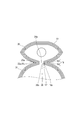
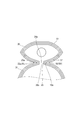
 このため、図17に示すように、本実施形態に係るシート材容器100は、底マチ13を有しておらず、胴部11の第1主面部20aと第2主面部20b(不図示)とが直接接続されている構成となっている。そして、面間接続部65は、第1主面部20aと第2主面部20bとの境界に配置されており、第1主面部20aにおける第1充填部61と、第2主面部20bにおける第2充填部62とが、面間接続部65を介して繋がっている。
 すなわち、本実施形態の場合、容器本体20は、胴部11を有し、胴部11の一方の主面部(第1主面部20a)が第1面状部であり、胴部11の他方の主面部(第2主面部20b)が第2面状部である。
 より詳細には、本実施形態の場合、充填部60は、一方の主面部(第1主面部20a)の周縁部に沿って形成されている第1充填部61と、他方の主面部(第2主面部20b)の周縁部に沿って形成されている第2充填部62とを有し、第1充填部61と第2充填部62とが、面間接続部65を介して繋がっている。
As shown in FIG. 16, in the case of the present embodiment, the container constituent sheet material 51 constituting the sheet material container 100 is a first sheet portion 31 serving as a first main surface portion 20a and a second sheet serving as a second main surface portion 20b. It has a portion 32 and a top gusset constituent sheet portion 39 that serves as a top gusset 14, but does not have a bottom gusset constituent sheet portion 38 that serves as a bottom gusset 13 (see FIG. 10). In the case of the present embodiment, the connecting portion 24a of the non-joining portion 24 is arranged only at the boundary between the first sheet portion 31 and the second sheet portion 32.
Therefore, as shown in FIG. 17, the sheet material container 100 according to the present embodiment does not have the bottom gusset 13, and the first main surface portion 20a and the second main surface portion 20b of the body portion 11 (not shown). Is directly connected to. The face-to-face connecting portion 65 is arranged at the boundary between the first main surface portion 20a and the second main surface portion 20b, and the first filling portion 61 in the first main surface portion 20a and the second filling portion 61 in the second main surface portion 20b. The filling portion 62 is connected via the face-to-face connecting portion 65.
That is, in the case of the present embodiment, the container body 20 has a body portion 11, and one main surface portion (first main surface portion 20a) of the body portion 11 is a first surface-like portion, and the other of the body portions 11 The main surface portion (second main surface portion 20b) is the second surface-shaped portion.
More specifically, in the case of the present embodiment, the filling portion 60 includes a first filling portion 61 formed along the peripheral edge portion of one main surface portion (first main surface portion 20a) and the other main surface portion (first main surface portion 20a). It has a second filling portion 62 formed along the peripheral edge portion of the two main surface portions 20b), and the first filling portion 61 and the second filling portion 62 are connected via the face-to-face connecting portion 65. ..
 また、キャップ部70は、例えば、ポンプ部72、支持筒部74、ヘッド部73及びノズル部75を有しておらず、開閉蓋を有するスクリューキャップである。
 シート材容器100は、吐出口が下向きの姿勢(倒立姿勢)で自立するようになっていてもよいし、胴部11を載置面に寝かせて配置されるようになっていてもよい。
 本実施形態の場合も、第1面状部(第1主面部20a)と第2面状部(第2主面部20b)との境界において、折り曲げ線に沿った周縁シール部の端部が、面間接続部65と本体シール部との境界位置から離間しているため、面間接続部65を構成する外側フィルム層22と内側フィルム層23の動きが規制されにくい。
 このため、折り曲げ線に沿って折り曲げられた状態で、充填部に充填材を充填する際に、第1充填部61から面間接続部65を介して第4充填部64に良好に充填材を充填することができる。
Further, the cap portion 70 is, for example, a screw cap that does not have the pump portion 72, the support cylinder portion 74, the head portion 73, and the nozzle portion 75, but has an opening / closing lid.
The sheet material container 100 may be such that the discharge port is self-supporting in a downward posture (inverted posture), or the body portion 11 may be laid down on a mounting surface.
Also in the case of the present embodiment, at the boundary between the first surface-shaped portion (first main surface portion 20a) and the second surface-shaped portion (second main surface portion 20b), the end portion of the peripheral edge sealing portion along the bending line is formed. Since it is separated from the boundary position between the face-to-face connection portion 65 and the main body seal portion, the movements of the outer film layer 22 and the inner film layer 23 constituting the face-to-face connection portion 65 are less likely to be regulated.
Therefore, when the filling portion is filled with the filler in a state of being bent along the bending line, the filling portion is satisfactorily filled into the fourth filling portion 64 from the first filling portion 61 via the face-to-face connecting portion 65. Can be filled.
 本発明は上述の実施形態に限定されるものではなく、本発明の目的が達成される限りにおける種々の変形、改良等の態様も含む。
 また、シート材容器100の各種の構成要素は、個々に独立した存在である必要はなく、複数の構成要素が一個の部材として形成されていること、一つの構成要素が複数の部材で形成されていること、ある構成要素が他の構成要素の一部であること、ある構成要素の一部と他の構成要素の一部とが重複していること、等が許容される。
The present invention is not limited to the above-described embodiment, and includes various modifications, improvements, and the like as long as the object of the present invention is achieved.
Further, the various components of the sheet material container 100 do not have to be individually independent, and a plurality of components are formed as one member, and one component is formed of a plurality of members. It is permissible that a certain component is a part of another component, that a part of a certain component overlaps with a part of another component, and the like.
11 胴部
13 底マチ
14 天マチ
15 スパウト部材
15a 注出筒部
15b 板状部
15c、15d 開口
17 収容領域
18 内容物
19 周縁シール部
191 4層シール部
192 6層シール部
19a 端部
20 容器本体
20a 第1主面部
20b 第2主面部
21 本体構成シート材
22 外側フィルム層
22a 外縁
23 内側フィルム層
23a 外縁
24 非接合部
26 本体シール部
26a 境界位置
28 本体周縁シール部
41    内袋構成シート材41
41c 外縁
51 容器構成シート材
60 充填部
61 第1充填部
62 第2充填部
63 第3充填部
64 第4充填部
81、82、83、84、85、86 折り曲げ線
91 接合部
100 シート材容器
111 非シール部
11 Body 13 Bottom gusset 14 Top gusset 15 Spout member 15a Outlet cylinder part 15b Plate-shaped part 15c, 15d Opening 17 Storage area 18 Contents 19 Peripheral seal part 191 4-layer seal part 192 6-layer seal part 19a End 20 Container Main body 20a 1st main surface 20b 2nd main surface 21 Main body constituent sheet material 22 Outer film layer 22a Outer edge 23 Inner film layer 23a Outer edge 24 Non-joining part 26 Main body sealing part 26a Boundary position 28 Main body peripheral sealing part 41 Inner bag constituent sheet material 41
41c Outer edge 51 Container constituent Sheet material 60 Filling part 61 First filling part 62 Second filling part 63 Third filling part 64 Fourth filling part 81, 82, 83, 84, 85, 86 Bending line 91 Joint part 100 Sheet material container 111 Non-sealed part

Claims (21)

  1.  相互に積層された外側フィルム層と内側フィルム層とを有する本体構成シート材を含む1又は複数のシート材を備えて構成されているシート材容器であって、
     内容物を収容する収容領域と、
     前記本体構成シート材により構成されており、前記収容領域を包囲している容器本体と、
     を備え、
     前記本体構成シート材は、前記外側フィルム層と前記内側フィルム層との接合部である本体シール部と、前記外側フィルム層と前記内側フィルム層とが部分的に非接合とされた非接合部と、を有するとともに、前記非接合部における前記外側フィルム層と前記内側フィルム層との層間に充填材を封入可能なされている充填部を有し、
     当該シート材容器は、前記1又は複数のシート材が折り曲げ線に沿って折り曲げられるとともに、少なくとも前記1又は複数のシート材のうち最内層のシート材の周縁部における一部分どうしが相互に接合されている周縁シール部を有し、
     前記周縁シール部によって前記収容領域が画定されており、
     前記容器本体は、複数の面状部を備えており、
     前記複数の面状部には、互いに隣り合っている第1面状部と第2面状部とが含まれ、
     前記充填部は、前記第1面状部と前記第2面状部との境界を介して前記第1面状部と前記第2面状部とに跨がって配置されている面間接続部を含み、
     前記境界において、前記折り曲げ線に沿った前記周縁シール部の端部が、前記面間接続部と本体シール部との境界位置から離間しているシート材容器。
    A sheet material container comprising one or a plurality of sheet materials including a main body constituent sheet material having an outer film layer and an inner film layer laminated on each other.
    A storage area for accommodating the contents and
    A container body that is composed of the main body constituent sheet material and surrounds the storage area, and a container main body.
    With
    The main body constituent sheet material includes a main body sealing portion which is a joint portion between the outer film layer and the inner film layer, and a non-bonded portion in which the outer film layer and the inner film layer are partially non-bonded. , And a filling portion in which a filler can be sealed between the outer film layer and the inner film layer in the non-joining portion.
    In the sheet material container, the one or more sheet materials are bent along a bending line, and at least a part of the one or more sheet materials at the peripheral edge of the innermost sheet material is joined to each other. Has a peripheral seal that is
    The accommodation area is defined by the peripheral seal portion, and the accommodation area is defined by the peripheral seal portion.
    The container body includes a plurality of planar portions, and the container body has a plurality of planar portions.
    The plurality of planar portions include a first planar portion and a second planar portion that are adjacent to each other.
    The filling portion is an inter-plane connection arranged so as to straddle the first planar portion and the second planar portion via a boundary between the first planar portion and the second planar portion. Including part
    A sheet material container in which the end portion of the peripheral edge seal portion along the bending line is separated from the boundary position between the face-to-face connection portion and the main body seal portion at the boundary.
  2.  前記境界において、前記折り曲げ線に沿った前記周縁シール部の幅寸法が前記本体シール部の幅寸法以上である請求項1に記載のシート材容器。 The sheet material container according to claim 1, wherein the width dimension of the peripheral edge seal portion along the bending line at the boundary is equal to or larger than the width dimension of the main body seal portion.
  3.  前記境界において、前記折り曲げ線に沿った前記周縁シール部の幅寸法が前記本体シール部の幅寸法よりも大きい請求項1に記載のシート材容器。 The sheet material container according to claim 1, wherein the width dimension of the peripheral edge seal portion along the bending line at the boundary is larger than the width dimension of the main body seal portion.
  4.  前記境界において、前記折り曲げ線に沿った前記周縁シール部の幅寸法と前記本体シール部の幅寸法との合計値が、前記面間接続部の幅寸法の半分よりも大きい請求項1から3のいずれか一項に記載のシート材容器。 Claims 1 to 3 in which the total value of the width dimension of the peripheral edge seal portion and the width dimension of the main body seal portion along the bending line at the boundary is larger than half of the width dimension of the face-to-face connection portion. The sheet material container according to any one item.
  5.  前記境界において、前記周縁シール部に対して前記本体シール部が隣接している請求項1から4のいずれか一項に記載のシート材容器。 The sheet material container according to any one of claims 1 to 4, wherein the main body sealing portion is adjacent to the peripheral sealing portion at the boundary.
  6.  前記面間接続部の存在する位置において、当該シート材容器を構成するフィルム層どうしがすべて非接合となっている請求項1から5のいずれか一項に記載のシート材容器。 The sheet material container according to any one of claims 1 to 5, wherein the film layers constituting the sheet material container are all non-bonded at the position where the face-to-face connection portion exists.
  7.  前記周縁シール部において、当該シート材容器を構成する全てのフィルム層が接合されている請求項1から6のいずれか一項に記載のシート材容器。 The sheet material container according to any one of claims 1 to 6, wherein all the film layers constituting the sheet material container are joined in the peripheral seal portion.
  8.  前記第2面状部には、前記収容領域から前記内容物を吐出する吐出口が設けられている請求項1から7のいずれか一項に記載のシート材容器。 The sheet material container according to any one of claims 1 to 7, wherein the second surface portion is provided with a discharge port for discharging the contents from the storage area.
  9.  前記第2面状部には、前記吐出口と連通する開口を有する板状部が設けられており、
     前記板状部に対して、前記1又は複数のシート材が接合されている請求項8に記載のシート材容器。
    The second surface-shaped portion is provided with a plate-shaped portion having an opening communicating with the discharge port.
    The sheet material container according to claim 8, wherein the one or a plurality of sheet materials are joined to the plate-shaped portion.
  10.  前記容器本体は、胴部と天部とを有し、
     前記胴部の一方の主面部が前記第1面状部であり、
     前記天部が前記第2面状部である請求項2から9のいずれか一項に記載のシート材容器。
    The container body has a body and a top, and has a body and a top.
    One main surface portion of the body portion is the first surface-shaped portion.
    The sheet material container according to any one of claims 2 to 9, wherein the top portion is the second planar portion.
  11.  前記天部には、前記収容領域から前記内容物を吐出する吐出口が設けられており、
     前記充填部は、前記主面部の周縁部に沿って形成されている第1充填部と、前記天部における前記吐出口の周囲に形成されている第4充填部と、を有し、
     前記第1充填部と前記第4充填部とが、前記面間接続部を介して繋がっている請求項10に記載のシート材容器。
    The top portion is provided with a discharge port for discharging the contents from the accommodation area.
    The filling portion has a first filling portion formed along the peripheral edge portion of the main surface portion and a fourth filling portion formed around the discharge port in the top portion.
    The sheet material container according to claim 10, wherein the first filling portion and the fourth filling portion are connected via the face-to-face connection portion.
  12.  前記容器本体は、胴部と底部とを有し、
     前記胴部の一方の主面部が前記第1面状部であり、
     前記底部が前記第2面状部である請求項1から7のいずれか一項に記載のシート材容器。
    The container body has a body and a bottom, and has a body and a bottom.
    One main surface portion of the body portion is the first surface-shaped portion.
    The sheet material container according to any one of claims 1 to 7, wherein the bottom portion is the second surface-shaped portion.
  13.  前記充填部は、前記主面部の周縁部に沿って形成されている第1充填部と、前記底部の周縁部に沿って形成されている第3充填部と、を有し、
     前記第1充填部と前記第3充填部とが、前記面間接続部を介して繋がっている請求項12に記載のシート材容器。
    The filling portion has a first filling portion formed along the peripheral edge portion of the main surface portion and a third filling portion formed along the peripheral edge portion of the bottom portion.
    The sheet material container according to claim 12, wherein the first filling portion and the third filling portion are connected via the face-to-face connection portion.
  14.  前記容器本体は、胴部を有し、
     前記胴部の一方の主面部が前記第1面状部であり、前記胴部の他方の主面部が前記第2面状部である請求項1から7のいずれか一項に記載のシート材容器。
    The container body has a body and
    The sheet material according to any one of claims 1 to 7, wherein one main surface portion of the body portion is the first surface-shaped portion, and the other main surface portion of the body portion is the second surface-shaped portion. container.
  15.  前記充填部は、前記一方の主面部の周縁部に沿って形成されている第1充填部と、前記他方の主面部の周縁部に沿って形成されている第2充填部と、を有し、
     前記第1充填部と前記第2充填部とが、前記面間接続部を介して繋がっている請求項14に記載のシート材容器。
    The filling portion has a first filling portion formed along the peripheral edge portion of the one main surface portion and a second filling portion formed along the peripheral edge portion of the other main surface portion. ,
    The sheet material container according to claim 14, wherein the first filling portion and the second filling portion are connected via the face-to-face connection portion.
  16.  前記面間接続部は、当該シート材容器の横幅方向における中央部に配置されている請求項1から15のいずれか一項に記載のシート材容器。 The sheet material container according to any one of claims 1 to 15, wherein the face-to-face connection portion is arranged at a central portion in the width direction of the sheet material container.
  17.  前記容器本体の内側に配置されている内袋を更に備え、
     前記内袋は、前記1又は複数のシート材のうち最内層のシート材である内袋構成シート材により構成されている請求項1から16のいずれか一項に記載のシート材容器。
    Further provided with an inner bag arranged inside the container body,
    The sheet material container according to any one of claims 1 to 16, wherein the inner bag is made of an inner bag constituent sheet material which is the innermost layer sheet material of the one or a plurality of sheet materials.
  18.  前記境界において、前記外側フィルム層の外縁、前記内側フィルム層の外縁、及び、前記内袋構成シート材の外縁が、互いに一致している請求項17に記載のシート材容器。 The sheet material container according to claim 17, wherein at the boundary, the outer edge of the outer film layer, the outer edge of the inner film layer, and the outer edge of the inner bag constituent sheet material coincide with each other.
  19.  前記境界において、前記外側フィルム層の外縁よりも前記内側フィルム層の外縁が内側に配置されている請求項1から17のいずれか一項に記載のシート材容器。 The sheet material container according to any one of claims 1 to 17, wherein the outer edge of the inner film layer is arranged inside the outer edge of the outer film layer at the boundary.
  20.  前記充填部は、前記面間接続部において括れている請求項1から19のいずれか一項に記載のシート材容器。 The sheet material container according to any one of claims 1 to 19, wherein the filling portion is enclosed in the face-to-face connection portion.
  21.  前記充填部に充填材が封入されている請求項1から20のいずれか一項に記載のシート材容器。 The sheet material container according to any one of claims 1 to 20, wherein a filler is sealed in the filling portion.
PCT/JP2020/011229 2020-03-13 2020-03-13 Sheet material container WO2021181691A1 (en)

Priority Applications (6)

Application Number Priority Date Filing Date Title
CN202080098430.5A CN115279663B (en) 2020-03-13 2020-03-13 Sheet container
US17/906,120 US11858708B2 (en) 2020-03-13 2020-03-13 Sheet member container
JP2022505716A JP7360535B2 (en) 2020-03-13 2020-03-13 sheet material container
EP20924591.9A EP4119462A4 (en) 2020-03-13 2020-03-13 Sheet material container
PCT/JP2020/011229 WO2021181691A1 (en) 2020-03-13 2020-03-13 Sheet material container
TW110108518A TW202140341A (en) 2020-03-13 2021-03-10 Sheet material container

Applications Claiming Priority (1)

Application Number Priority Date Filing Date Title
PCT/JP2020/011229 WO2021181691A1 (en) 2020-03-13 2020-03-13 Sheet material container

Publications (1)

Publication Number Publication Date
WO2021181691A1 true WO2021181691A1 (en) 2021-09-16

Family

ID=77672174

Family Applications (1)

Application Number Title Priority Date Filing Date
PCT/JP2020/011229 WO2021181691A1 (en) 2020-03-13 2020-03-13 Sheet material container

Country Status (6)

Country Link
US (1) US11858708B2 (en)
EP (1) EP4119462A4 (en)
JP (1) JP7360535B2 (en)
CN (1) CN115279663B (en)
TW (1) TW202140341A (en)
WO (1) WO2021181691A1 (en)

Citations (4)

* Cited by examiner, † Cited by third party
Publication number Priority date Publication date Assignee Title
JP2006240651A (en) * 2005-03-02 2006-09-14 Toppan Printing Co Ltd Self-supporting flexible packaging bag
JP2016535708A (en) * 2013-11-06 2016-11-17 ザ プロクター アンド ギャンブル カンパニー Flexible container and manufacturing method thereof
JP6153185B1 (en) 2015-09-09 2017-06-28 花王株式会社 Sheet material container
WO2018163269A1 (en) * 2017-03-07 2018-09-13 花王株式会社 Container

Family Cites Families (47)

* Cited by examiner, † Cited by third party
Publication number Priority date Publication date Assignee Title
US5261881A (en) * 1990-03-28 1993-11-16 R. Myles Riner, M.D., Professional Corporation Non-reusable dispensing apparatus
US5174458A (en) * 1992-05-12 1992-12-29 Colgate-Palmolive Company Collapsible container
NZ519006A (en) * 1999-11-10 2006-12-22 Scholle Corp Collapsible bag for dispensing liquids and method
US6176613B1 (en) * 2000-05-04 2001-01-23 Tzan-Kuo Chen Packing bag with air cushion
AR034176A1 (en) * 2000-11-08 2004-02-04 Graham Packaging Pet Tech METHOD OF PRODUCTION OF A PLASTIC CONTAINER IN A COMPRESSIBLE TUBE, INTERMEDIATE ARTICLE FOR USE IN THE FORMATION OF A PLASTIC CONTAINER IN A COMPRIMIBLE TUBE, AND PLASTIC CONTAINER IN A COMPRIMIBLE TUBE
US8960183B2 (en) * 2001-02-16 2015-02-24 Solar Solutions Llc Solar water pasteurizer
JP5124085B2 (en) * 2005-08-24 2013-01-23 押尾産業株式会社 Self-supporting bag and its manufacturing method
JP2010512291A (en) * 2006-12-11 2010-04-22 ポリィ−ディー・エルエルシー Vertical pouch
WO2012073004A2 (en) * 2010-11-29 2012-06-07 Ian Darby Container, container blank, and method of manufacture
EP2879972B1 (en) * 2012-08-06 2017-05-17 The Procter and Gamble Company Method of forming a flexible container
CN105408225B (en) * 2013-08-01 2017-08-01 宝洁公司 Enhancing and the haptic interaction of the membranous wall packaging of the structural support system with inflation are acted on
CN105408226B (en) * 2013-08-01 2018-06-08 宝洁公司 Disposable flexible container with surface element
CA2926868A1 (en) * 2013-10-11 2015-04-16 The Procter & Gamble Company Disposable flexible container
EP3066024B1 (en) * 2013-11-06 2017-12-20 The Procter and Gamble Company Flexible containers with vent systems
ES2675922T3 (en) * 2013-11-06 2018-07-13 The Procter & Gamble Company Flexible containers with flexible valves
WO2015069820A1 (en) * 2013-11-06 2015-05-14 The Procter & Gamble Company Easy to empty flexible containers
US9981759B2 (en) * 2013-11-06 2018-05-29 The Procter & Gamble Company Flexible containers and methods of making the same
USD753995S1 (en) * 2014-03-07 2016-04-19 Clear Lam Packaging, Inc. Film for packaging production
EP3233661A1 (en) * 2014-12-19 2017-10-25 The Procter and Gamble Company A line-up of flexible containers
EP3233662A1 (en) * 2014-12-19 2017-10-25 The Procter and Gamble Company Method for making a line-up of flexible containers
US20160176582A1 (en) * 2014-12-19 2016-06-23 The Procter & Gamble Company Flexible Containers with Easily Variable Sizing
US20160176597A1 (en) * 2014-12-19 2016-06-23 The Procter & Gamble Company Flexible Containers with Easily Variable Sizing
CN107108096A (en) * 2014-12-19 2017-08-29 宝洁公司 Serial method for preparing flexible container
CA2981731C (en) * 2015-04-10 2019-03-12 Kenneth Stephen Mcguire Flexible containers with product dispensing visibility
CN107406184B (en) * 2015-04-10 2019-07-12 宝洁公司 Flexible container with integral dispensing jet pipe
US20160297591A1 (en) * 2015-04-10 2016-10-13 The Procter & Gamble Company Flexible Containers with Intermediate Bottom Members
CN107848684B (en) * 2015-04-10 2019-10-18 宝洁公司 Flexible container with corrugated turning
CA2983340C (en) * 2015-05-06 2019-06-11 The Procter & Gamble Company Method of forming flexible containers with gussets
WO2017004106A1 (en) * 2015-06-30 2017-01-05 The Procter & Gamble Company Flexible containers with removable portions
US10457457B2 (en) * 2016-04-26 2019-10-29 The Procter & Gamble Company Flexible containers with bottom support structure
JP6817810B2 (en) * 2016-12-28 2021-01-20 花王株式会社 Sheet material container
EP3593984A4 (en) * 2017-03-07 2020-12-30 Fuji Seal International, Inc. Method for manufacturing intermediate material for soft packaging container, method for manufacturing soft packaging container, and method for manufacturing soft packaging container packaging body
US11261008B2 (en) * 2017-03-07 2022-03-01 Kao Corporation Sheet material container
EP3483085A4 (en) * 2017-03-07 2020-03-11 Kao Corporation Sheet material container
JP6543306B2 (en) * 2017-07-31 2019-07-10 花王株式会社 Sheet material container
JP6822917B2 (en) * 2017-07-31 2021-01-27 花王株式会社 Sheet material container
JP6803306B2 (en) * 2017-08-09 2020-12-23 花王株式会社 container
JP7146447B2 (en) * 2018-05-21 2022-10-04 花王株式会社 sheet container
JP7142473B2 (en) * 2018-06-12 2022-09-27 花王株式会社 sheet container
JP6775709B1 (en) * 2018-11-26 2020-10-28 花王株式会社 Sheet material container
CN113039131A (en) * 2019-08-30 2021-06-25 花王株式会社 Container with a lid
WO2021049385A1 (en) * 2019-09-09 2021-03-18 株式会社フジシールインターナショナル Sheet material container
CN115298103B (en) * 2020-03-13 2024-04-05 花王株式会社 Sheet container
US11673727B2 (en) * 2021-03-03 2023-06-13 Scholle Ipn Corporation Dispensing system for a flexible bag, flexible bag assembly
WO2023037686A1 (en) * 2021-09-09 2023-03-16 株式会社フジシール Pouch
WO2023105941A1 (en) * 2021-12-08 2023-06-15 株式会社フジシールインターナショナル Pouch container and production method thereof
US20230211576A1 (en) * 2022-01-04 2023-07-06 The Glad Products Company Expanding storage bags

Patent Citations (4)

* Cited by examiner, † Cited by third party
Publication number Priority date Publication date Assignee Title
JP2006240651A (en) * 2005-03-02 2006-09-14 Toppan Printing Co Ltd Self-supporting flexible packaging bag
JP2016535708A (en) * 2013-11-06 2016-11-17 ザ プロクター アンド ギャンブル カンパニー Flexible container and manufacturing method thereof
JP6153185B1 (en) 2015-09-09 2017-06-28 花王株式会社 Sheet material container
WO2018163269A1 (en) * 2017-03-07 2018-09-13 花王株式会社 Container

Non-Patent Citations (1)

* Cited by examiner, † Cited by third party
Title
See also references of EP4119462A4

Also Published As

Publication number Publication date
US11858708B2 (en) 2024-01-02
CN115279663A (en) 2022-11-01
US20230150743A1 (en) 2023-05-18
EP4119462A1 (en) 2023-01-18
EP4119462A4 (en) 2023-12-06
CN115279663B (en) 2024-04-16
JP7360535B2 (en) 2023-10-12
JPWO2021181691A1 (en) 2021-09-16
TW202140341A (en) 2021-11-01

Similar Documents

Publication Publication Date Title
JP6193535B1 (en) container
JP7212493B2 (en) Container sheet
JP6879784B2 (en) Sheet material container
JP6803306B2 (en) container
JP6186547B1 (en) Sheet material container
CN109641681B (en) Sheet material container
JP7142473B2 (en) sheet container
JP6817810B2 (en) Sheet material container
JP2018144885A (en) Sheet material container
WO2021181689A1 (en) Sheet material container
WO2021181691A1 (en) Sheet material container
WO2021181692A1 (en) Container
WO2021224995A1 (en) Sheet material container manufacturing method
WO2021181690A1 (en) Container
JP7121625B2 (en) container
JP7365222B2 (en) container
JP2021155062A (en) container
JP2021176765A (en) Manufacturing method for sheet material container
JP2020083426A (en) Sheet material container
JP6960515B2 (en) Sheet material container
WO2022009276A1 (en) Method for producing sheet material container filled with content
JP2022102203A (en) Container of sheet material
JP2021172387A (en) container
JP2023116885A (en) Sheet material container
JP2023005523A (en) Sheet material container

Legal Events

Date Code Title Description
121 Ep: the epo has been informed by wipo that ep was designated in this application

Ref document number: 20924591

Country of ref document: EP

Kind code of ref document: A1

ENP Entry into the national phase

Ref document number: 2022505716

Country of ref document: JP

Kind code of ref document: A

WWE Wipo information: entry into national phase

Ref document number: 2020924591

Country of ref document: EP

ENP Entry into the national phase

Ref document number: 2020924591

Country of ref document: EP

Effective date: 20221013

NENP Non-entry into the national phase

Ref country code: DE