WO2021131786A1 - メス端子、コネクタ、及びワイヤーハーネス - Google Patents
メス端子、コネクタ、及びワイヤーハーネス Download PDFInfo
- Publication number
- WO2021131786A1 WO2021131786A1 PCT/JP2020/046258 JP2020046258W WO2021131786A1 WO 2021131786 A1 WO2021131786 A1 WO 2021131786A1 JP 2020046258 W JP2020046258 W JP 2020046258W WO 2021131786 A1 WO2021131786 A1 WO 2021131786A1
- Authority
- WO
- WIPO (PCT)
- Prior art keywords
- female terminal
- spring piece
- piece
- contact
- convex portion
- Prior art date
Links
Images


Classifications
-
- H—ELECTRICITY
- H01—ELECTRIC ELEMENTS
- H01R—ELECTRICALLY-CONDUCTIVE CONNECTIONS; STRUCTURAL ASSOCIATIONS OF A PLURALITY OF MUTUALLY-INSULATED ELECTRICAL CONNECTING ELEMENTS; COUPLING DEVICES; CURRENT COLLECTORS
- H01R13/00—Details of coupling devices of the kinds covered by groups H01R12/70 or H01R24/00 - H01R33/00
- H01R13/02—Contact members
- H01R13/10—Sockets for co-operation with pins or blades
- H01R13/11—Resilient sockets
- H01R13/115—U-shaped sockets having inwardly bent legs, e.g. spade type
-
- H—ELECTRICITY
- H01—ELECTRIC ELEMENTS
- H01R—ELECTRICALLY-CONDUCTIVE CONNECTIONS; STRUCTURAL ASSOCIATIONS OF A PLURALITY OF MUTUALLY-INSULATED ELECTRICAL CONNECTING ELEMENTS; COUPLING DEVICES; CURRENT COLLECTORS
- H01R13/00—Details of coupling devices of the kinds covered by groups H01R12/70 or H01R24/00 - H01R33/00
- H01R13/02—Contact members
- H01R13/03—Contact members characterised by the material, e.g. plating, or coating materials
-
- H—ELECTRICITY
- H01—ELECTRIC ELEMENTS
- H01R—ELECTRICALLY-CONDUCTIVE CONNECTIONS; STRUCTURAL ASSOCIATIONS OF A PLURALITY OF MUTUALLY-INSULATED ELECTRICAL CONNECTING ELEMENTS; COUPLING DEVICES; CURRENT COLLECTORS
- H01R13/00—Details of coupling devices of the kinds covered by groups H01R12/70 or H01R24/00 - H01R33/00
- H01R13/02—Contact members
- H01R13/10—Sockets for co-operation with pins or blades
- H01R13/11—Resilient sockets
- H01R13/113—Resilient sockets co-operating with pins or blades having a rectangular transverse section
Definitions
- the present disclosure relates to female terminals, connectors, and wire harnesses.
- This application claims priority based on Japanese Patent Application No. 2019-237239 dated December 26, 2019, and incorporates all the contents described in the Japanese application.
- a male terminal and a female terminal are used as described in FIG. 9 of Patent Document 1.
- the female terminal typically includes a spring piece and a tubular portion for accommodating the spring piece.
- the male terminal inserted from the open end of the cylinder presses the spring piece, and the spring piece urges the male terminal.
- the male terminal and the female terminal are electrically connected.
- the spring piece of the female terminal described in Patent Document 1 is formed by bending a plurality of strips integrally with a plate material constituting a square tubular portion inside the tubular portion. Specifically, the strip extends from the open end of one of the four peripheral wall portions constituting the tubular portion. The strip is folded back from the end of the opening toward the inside of the cylinder. Further, the band member is folded back toward the opening end at an intermediate position of the band member. Further, the tip end portion of the band member is bent toward the peripheral wall portion side facing the one peripheral wall portion having the band member. The spring piece made of such a strip is cantilevered and supported by the open end of the peripheral wall portion of the tubular portion.
- each of the two spring pieces is cantilevered and supported by two facing peripheral wall portions of the four peripheral wall portions constituting the square tubular tubular portion.
- the two spring pieces facing each other sandwich the male terminal and urge.
- the female terminal of the present disclosure is A female terminal including a cylinder portion and a spring piece arranged inside the cylinder portion.
- the tubular portion includes an open end into which a male terminal is inserted, and a first inner surface and a second inner surface facing each other across the spring piece.
- the first inner surface is a surface that cantilever-supports the spring piece.
- the spring piece includes a front side region facing the male terminal, a back side region arranged on the first inner surface side, and at least one convex portion provided on the back side region. The convex portion locally protrudes toward the first inner surface.
- the connectors of the present disclosure are A female terminal of the present disclosure and a housing for holding the female terminal are provided.
- the wire harness of the present disclosure is The connector of the present disclosure and an electric wire connected to the female terminal are provided.
- FIG. 1 is a side view of the female terminal of the first embodiment as viewed from a direction orthogonal to the axial direction of the tubular portion.
- FIG. 2 is a cross-sectional view of the female terminal shown in FIG. 1 in which the tubular portion and the spring piece are cut along the II-II cutting line shown in FIG.
- FIG. 3 is a cross-sectional view of the female terminal shown in FIG. 1 in which the tubular portion and the spring piece are cut along the III-III cutting line shown in FIG.
- FIG. 4 is a cross-sectional view schematically showing an enlarged area on the surface side of the female terminal of the first embodiment.
- FIG. 5 is a cross-sectional view of the female terminal of the second embodiment, in which the tubular portion and the spring piece are cut in a plane orthogonal to the axial direction of the tubular portion.
- FIG. 6 is a cross-sectional view of the female terminal of the third embodiment, in which the tubular portion and the spring piece are cut in a plane orthogonal to the axial direction of the tubular portion.
- FIG. 7 is a cross-sectional view of the female terminal of the fourth embodiment, in which the tubular portion and the spring piece are cut in a plane orthogonal to the axial direction of the tubular portion.
- FIG. 8 is a cross-sectional view of the female terminal of the fifth embodiment, in which the tubular portion and the spring piece are cut in a plane orthogonal to the axial direction of the tubular portion.
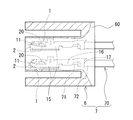
- FIG. 9 is a side view showing the connector of the embodiment and the wire harness of the embodiment.
- FIG. 10 is a graph showing the relationship between the contact load and the friction coefficient in Test Example 1.
- FIG. 11 is a graph showing the relationship between the contact pressure and the friction coefficient in Test Example 1.
- a female terminal that makes it easy to insert a male terminal is desired.
- the female terminal is typically used as an electrical connection member in a female connector.
- a female connector having a plurality of female terminals and a male connector having a plurality of male terminals are fitted together, each male terminal is inserted into each female terminal at the same time. Therefore, if it is difficult to insert each male terminal into each female terminal because the spring piece of each female terminal obstructs the insertion of each male terminal, the force when fitting the male connector and the female connector tends to increase. .. As the number of male terminals and the number of female terminals increases, the above-mentioned fitting force increases. Therefore, the burden on the operator increases in the connection between the male connector and the female connector.
- one of the purposes of the present disclosure is to provide a female terminal into which a male terminal can be easily inserted.
- Another object of the present disclosure is to provide a connector into which a male terminal can be easily inserted and a wire harness.
- the female terminal of the present disclosure, the connector of the present disclosure, and the wire harness of the present disclosure are excellent in the insertability of the male terminal.
- the present inventors have obtained the following findings regarding a female terminal including a tubular portion and a spring piece.
- the male terminal inserted into the tubular portion presses the spring piece toward the inner surface of the peripheral wall portion that cantilevers and supports the spring piece, for example, among the peripheral wall portions constituting the tubular portion. Due to this pressing, the portion of the spring piece facing the inner surface comes into contact with the inner surface. Further, as the male terminal advances in the tubular portion, the portion of the spring piece facing the inner surface slides on the inner surface. It can be said that the smaller the coefficient of friction between the spring piece and the inner surface in this sliding state, the less likely the spring piece will hinder the insertion of the male terminal.
- the male terminal easily enters the female terminal. Further, the larger the pressure when the portion of the spring piece facing the inner surface comes into contact with the inner surface, the smaller the friction coefficient tends to be.
- the female terminal of the present disclosure is based on the above findings.
- the above pressure that is, the pressure when the spring piece provided in the female terminal comes into contact with the inner surface of the tubular portion may be referred to as a contact pressure.
- the female terminal according to one aspect of the present disclosure is A female terminal including a cylinder portion and a spring piece arranged inside the cylinder portion.
- the tubular portion includes an open end into which a male terminal is inserted, and a first inner surface and a second inner surface facing each other across the spring piece.
- the first inner surface is a surface that cantilever-supports the spring piece.
- the spring piece includes a front side region facing the male terminal, a back side region arranged on the first inner surface side, and at least one convex portion provided on the back side region. The convex portion locally protrudes toward the first inner surface.
- the female terminal of the present disclosure can reduce the contact area between the spring piece and the first inner surface of the tubular portion by the convex portion. Since the contact area is small, the contact pressure is likely to increase as described later. Therefore, the coefficient of friction between the spring piece and the first inner surface of the cylinder when the male terminal is inserted into the cylinder tends to be small. Such a female terminal of the present disclosure is excellent in insertability of the male terminal because the male terminal can easily enter the tubular portion.
- the convex portion is convex.
- the portion and its vicinity are slippery on the first inner surface. Surface contact does not substantially occur depending on the shape, size, etc. of the convex portion. From these points as well, the female terminal of the present disclosure is excellent in the insertability of the male terminal.
- the width direction is defined as a direction orthogonal to both the direction in which the first inner surface and the second inner surface face each other and the axial direction.
- the backside region comprises a portion where each of the widthwise side edges approaches the first inner surface and the central portion in the width direction is curved away from the first inner surface.
- Examples of the convex portion include a form including the side edge portion.
- the above form has two convex parts. Therefore, the contact between the spring piece and the first inner surface of the tubular portion tends to be two-point contact. In this respect, the above-mentioned contact area tends to be small. Further, in the above embodiment, it is easy to maintain a state in which the two convex portions are in contact with the first inner surface and the portion of the spring piece other than the convex portions is not in contact with the first inner surface. Therefore, the state where the contact area is small is easily maintained.
- the width direction is defined as a direction orthogonal to both the direction in which the first inner surface and the second inner surface face each other and the axial direction.
- the back side region includes a portion where each of the lateral edge portions in the width direction is separated from the first inner surface and the central portion in the width direction is curved so as to approach the first inner surface.
- Examples of the convex portion include a form including the central portion.
- the above form includes one convex portion. Therefore, the contact between the spring piece and the first inner surface of the cylinder portion tends to be a single point contact. In this respect, the above-mentioned contact area tends to be small.
- the central portion in the width direction of the first inner surface is separated from the second inner surface, and the lateral edge portion of the first inner surface in the width direction approaches the second inner surface.
- a form having such a curved shape can be mentioned.
- the convex portion may have a form including an embossed portion.
- the convex portion can have a shape that allows point contact, for example. Therefore, the above-mentioned contact area tends to be smaller.
- a base material and a plating layer covering at least a part of the surface of the base material are provided.
- the portion covering the first inner surface and the portion covering the convex portion include a surface layer made of the same type of material.
- the material may be in the form of a kind of metal selected from the group consisting of pure tin, tin alloys, sterling silver, and silver alloys.
- the surface layer on the first inner surface side and the surface layer on the convex portion side are made of a material that easily adheres.
- the convex portion can penetrate the surface layer on the first inner surface side and come into contact with a portion inside the surface layer. As a result, adhesion is unlikely to occur. Therefore, the above-mentioned form can easily prevent the above-mentioned friction coefficient from increasing due to adhesion.
- At least one of the thickness of the portion covering the first inner surface and the portion covering the convex portion is thinner than the thickness of the portion covering the first inner surface and the portion other than the convex portion.
- the above-mentioned form can further prevent the above-mentioned friction coefficient from increasing due to adhesion.
- the spring piece is It is composed of strips that are bent into a predetermined shape.
- a base piece forming the front side region and a tip piece forming the back side region are provided.
- the base piece extends from the open end toward the inside of the cylinder.
- the tip piece is folded back from the base piece toward the open end. Examples thereof include a mode in which the ratio L1 / L2 is 0.51 or less when the length of the tip piece is L1 and the length of the base piece is L2.
- the spring constant of the spring piece tends to be large. Therefore, in the above form, the contact state with the male terminal can be maintained satisfactorily. Further, in the above embodiment, the total length of the strip material constituting the spring piece is shorter than that in the case where the length of the base piece is the same and the ratio L1 / L2 is more than 0.51. Therefore, the above-mentioned form is small and lightweight.
- the spring piece is It is composed of strips that are bent into a predetermined shape.
- a base piece forming the front side region and a tip piece forming the back side region are provided.
- the base piece extends from the open end toward the inside of the cylinder.
- the tip piece is folded back from the base piece toward the open end. Examples thereof include a form in which the length of the tip piece is less than 2.4 mm.
- the total length of the strip material constituting the spring piece is shorter than that in the case where the length of the tip piece is 2.4 mm or more. Therefore, the above-mentioned form is small and lightweight.
- the connector according to one aspect of the present disclosure is The female terminal according to any one of (1) to (9) above and a housing for holding the female terminal are provided.
- the connector of this disclosure has excellent insertability of male terminals.
- the connector of the present disclosure is a multi-pole connector including a plurality of female terminals
- the connector of the present disclosure and the male connector are easily fitted. Therefore, the connector of the present disclosure can reduce the burden on the operator in connection with the male connector.
- the wire harness according to one aspect of the present disclosure is The connector according to (10) above and an electric wire connected to the female terminal are provided.
- the wire harness of this disclosure has excellent insertability of male terminals.
- the connector provided in the wire harness of the present disclosure is the above-mentioned multi-pole connector, the connector and the male connector are easily fitted together. Therefore, the wire harness of the present disclosure can reduce the burden on the operator in connection with the male connector.
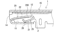
- FIG. 1 shows a direction in which the female terminal 1 of the first embodiment is orthogonal to the axial direction of the tubular portion 15 in a state where the female terminal 1 is arranged with the side where the tubular portion 15 cantilevers and supports the spring piece 2 as the lower side.
- FIG. 2 is a vertical cross-sectional view of the female terminal 1 of the first embodiment, in which the tubular portion 15 and the spring piece 2 are cut in a plane parallel to the axial direction and the height direction described later.
- FIG. 2 shows a portion of the tubular portion 15 for accommodating the spring piece 2.
- FIG. 3 is a cross-sectional view of the female terminal 1 of the first embodiment in which the tubular portion 15 and the spring piece 2 are cut in a plane orthogonal to the axial direction.
- FIG. 3 shows a portion of the spring piece 2 provided with the convex portion 20. It should be noted that FIGS. 1 to 3 and 5 to 9 described later show a state in which the male terminal 9 is not inserted into the tubular portion 15.
- the female terminal 1 of the first embodiment includes a tubular portion 15 and a spring piece 2.
- the spring piece 2 is arranged inside the tubular portion 15.
- a male terminal 9 is inserted into the tubular portion 15.
- the male terminal 9 inserted into the tubular portion 15 presses the spring piece 2, and the spring piece 2 urges the male terminal 9.
- the urging force of the spring piece 2 firmly maintains the contact state between the female terminal 1 and the male terminal 9.
- FIG. 1 virtually shows the male terminal 9 with a chain double-dashed line.
- the male terminal 9 is typically a rod-shaped member.
- the spring piece 2 has a specific shape. Specifically, the spring piece 2 includes at least one convex portion 20 in the back side region 25 that does not face the male terminal 9. The convex portion 20 locally protrudes toward the first inner surface 11 of the inner surface of the tubular portion 15 (FIG. 3). The first inner surface 11 is a surface that cantileverly supports the spring piece 2 (FIG. 2). In the female terminal 1, the convex portion 20 serves as a contact point with the first inner surface 11 of the spring piece 2. Such a female terminal 1 can reduce the contact area between the spring piece 2 and the first inner surface 11 of the tubular portion 15.
- a more detailed description will be given.
- the female terminal 1 of the first embodiment is typically a conductive member obtained by bending a plate material having a predetermined shape into a predetermined shape.
- the female terminal 1 includes a connection point with the male terminal 9 and a connection point with the electric wire 70 (FIG. 9 described later).
- Such a female terminal 1 is used, for example, as a member for electrically connecting a printed wiring board (not shown) connected to the male terminal 9 and an electronic / electrical device (not shown) connected to the electric wire 70.
- connection point with the male terminal 9 includes one tubular portion 15 and at least one spring piece 2.
- the tubular portion 15 of this example has a square tubular shape having a square end face shape and a cross-sectional shape (FIG. 3). Further, the female terminal 1 of this example includes one spring piece 2.
- connection point with the electric wire 70 typically includes a wire barrel portion 16 and an insulation barrel portion 17.
- FIG. 1 shows a state in which the female terminal 1 does not hold the electric wire 70. In this state, the band piece that wraps the electric wire 70 is not folded.
- the tubular portion 15 of this example includes four peripheral wall portions.
- a notch portion 18 to be a fold line is provided on the plate material before it is bent.
- the notch portion 18 is a linear notch extending along the axial direction of the tubular portion 15.
- the notch portion 18 bends the adjacent peripheral wall portions so as to be substantially orthogonal to each other. Therefore, the adjacent peripheral wall portions are arranged so as to be substantially orthogonal to each other.
- the corners formed by the adjacent peripheral walls are almost right angles.
- the four peripheral walls are equipped with two pairs of two peripheral walls facing each other.
- Each peripheral wall portion includes a portion composed of a flat flat plate piece.
- the left peripheral wall portion, the right peripheral wall portion, and the lower peripheral wall portion are composed of a substantially flat flat plate piece.
- the upper peripheral wall portion is composed of two plate pieces overlapping each other, but may be composed of one plate piece.
- the inner plate piece provided with the second inner surface 12 includes a bead portion protruding toward the inside of the tubular portion 15.
- the bead portion of this example is formed in a W shape.
- the tubular portion 15 includes a first inner surface 11 and a second inner surface 12 facing each other.
- the first inner surface 11 is the lower surface
- the second inner surface 12 is the upper surface.
- the first inner surface 11 is a substantially flat flat surface.
- the direction in which the first inner surface 11 and the second inner surface 12 face each other is referred to as a height direction.
- the height direction is the vertical direction in FIGS. 1 to 3 and 5 to 8 described later.
- the direction orthogonal to both the height direction and the axial direction of the tubular portion 15 is referred to as a width direction.
- the width direction is the direction in which two peripheral wall portions that do not have the first inner surface 11 and the second inner surface 12 face each other among the four peripheral wall portions. Further, the width direction is the left-right direction in FIGS. 3 and 5 to 8 described later.
- the axial direction is the left-right direction in FIGS. 1 and 2.
- Both ends of the tubular portion 15 are open. As shown in FIG. 1, one end of the tubular portion 15 is an open end 14 into which the male terminal 9 is inserted. On the other end side of the tubular portion 15, the wire barrel portion 16 and the insulation barrel portion 17 extend from the peripheral wall portion having the first inner surface 11.
- the spring piece 2 is sandwiched between the first inner surface 11 and the second inner surface 12 inside the tubular portion 15. Therefore, the spring piece 2 includes a region arranged on the first inner surface 11 side and a region arranged on the second inner surface 12 side.
- the region arranged on the second inner surface 12 side is the front side region 29 facing the male terminal 9.
- the front side region 29 includes a contact portion 290 in contact with the male terminal 9 (FIG. 2).
- the region arranged on the first inner surface 11 side is the back side region 25 that does not contact the male terminal 9.
- the spring piece 2 of this example is composed of a strip material bent into a predetermined shape. Specifically, as shown in FIG. 2, the strip extends from the opening end 14 of the peripheral wall portion having the first inner surface 11 of the four peripheral wall portions.
- the spring piece 2 is formed by bending the band member three times inside the tubular portion 15.
- the spring piece 2 made of such a band member is cantilevered and supported by the opening end 14 on the first inner surface 11 of the tubular portion 15 and is integrated with the tubular portion 15.
- the above-mentioned strip is folded back from the opening end 14 of the tubular portion 15 toward the inside of the tubular portion 15.
- the strip is folded back toward the opening end 14 at an intermediate position of the strip so that the first inner surface 11 side is inside the bend.
- the strip is bent from the first inner surface 11 side to the second inner surface 12 side at a position near the tip edge of the strip.
- press working or the like can be used for the bending work.
- the spring piece 2 of this example includes a base piece 22 and a tip piece 21.
- the base piece 22 constitutes the front side region 29.
- the tip piece 21 constitutes a part of the back side region 25.
- the base piece 22 is a portion folded back by the above-mentioned first bending. Therefore, the base piece 22 extends from the open end 14 toward the inside of the tubular portion 15. Further, the base piece 22 is arranged so as to intersect the first inner surface 11. Specifically, the base piece 22 is inclined so as to move away from the connection point with the opening end 14, that is, the root, and toward the first inner surface 11, that is, closer to the second inner surface 12. Therefore, the corner portion due to the second bending is arranged closer to the second inner surface 12 than the corner portion due to the first bending.
- the tip piece 21 is a portion folded back from the base piece 22 toward the opening end 14 by the second bending described above.
- the tip piece 21 and the base piece 22 are arranged so as to overlap each other in the height direction (FIG. 3). Therefore, the tip piece 21 does not come into contact with the male terminal 9.
- the tip edge of the spring piece 2 is arranged toward the second inner surface 12 side by the third bending described above.
- the tip edge is arranged upward in FIG.
- the outer corners are arranged facing the first inner surface 11. Therefore, this outer corner also constitutes the back side region 25. Further, the outer corner portion is a portion of the spring piece 2 that is arranged close to the first inner surface 11. That is, the outer corner portion is a portion where the distance to the first inner surface 11 is short.
- the spring piece 2 of this example includes two convex portions 20 at the outer corner portions described above.
- the back side region 25 is curved so that each of the side edge portions in the width direction approaches the first inner surface 11 and the central portion in the width direction is separated from the first inner surface 11. It has a part that has been removed. That is, the back side region 25 includes a portion curved toward the second inner surface 12, and a portion curved upward in FIG.
- the outer corner is the curved portion.
- the ridgeline of the outer corner is drawn as a convex curve above the above.
- Each convex portion 20 includes each side edge portion.
- FIG. 3 illustrates a case where each convex portion 20 is each side edge portion.
- the ridgeline forming the above-mentioned outer corner is curved over the entire ridgeline so as to draw one arc.
- the corner portion having such a curved shape is formed so as to warp the outer corner portion toward the second inner surface 12 side, for example, after the third bending or at the same time as the third bending.
- this curved shape is easier to form than the shapes shown in the fourth and fifth embodiments described later.
- the female terminal 1 of this example is excellent in manufacturability.
- the convex portion 20 is a portion of the spring piece 2 that is arranged closest to the first inner surface 11. That is, the convex portion 20 is the portion where the distance to the first inner surface 11 is the shortest. Therefore, when the male terminal 9 inserted into the tubular portion 15 presses the spring piece 2 toward the first inner surface 11, only the convex portion 20 or only the convex portion 20 and its vicinity is the first inner surface in the back side region 25. It touches 11. That is, in the back side region 25 of the spring piece 2, a state in which a portion other than the convex portion 20 is not in contact with the first inner surface 11 occurs. In this state, the contact area between the spring piece 2 and the first inner surface 11 of the tubular portion 15 is smaller than that in the case where the spring piece and the first inner surface 11 are in surface contact with each other.
- the above-mentioned outer corner portion has the above-mentioned specific curved shape, and the convex portion 20 is composed of the side edge portion of the spring piece 2. Therefore, the contact point of the spring piece 2 with the first inner surface 11 is a state close to two point contact by the biconvex portion 20 or two point contact. Therefore, the above-mentioned contact area is small. Further, the central portion in the width direction of the outer corner portion is difficult to contact the first inner surface 11 even if the spring piece 2 is pressed toward the first inner surface 11 by the male terminal 9.
- the contact area of the tubular portion 15 with the first inner surface 11 of the spring piece 2 is the contact area with the first inner surface 11 of the convex portion 20.
- the pressure applied by the convex portion 20 to the first inner surface 11, that is, the contact pressure is higher than in the case of the above-mentioned line contact or surface contact. Due to the high contact pressure, the coefficient of friction between the spring piece 2 and the first inner surface 11 tends to be small when the male terminal 9 is inserted into the tubular portion 15.
- the surface of the spring piece 2 and the surface of the first inner surface 11 are covered with a plating layer made of a material that easily adheres, as will be described later. Can be mentioned. If the above-mentioned contact pressure is large, the convex portion 20 can break through the easily stickable layer and come into contact with a portion inside the layer. As a result, it is difficult for the convex portion 20 and the first inner surface 11 to adhere to each other. Therefore, it is unlikely that the coefficient of friction will increase due to adhesion. As a result, the coefficient of friction between the spring piece 2 and the first inner surface 11 tends to be small.
- the distance between the front side region 29 of the spring piece 2 and the second inner surface 12 is widened. That is, in the tubular portion 15, the insertion point of the male terminal 9 becomes large. Therefore, the male terminal 9 can easily enter the tubular portion 15 without being hindered by the spring piece 2.
- the back side region 25 has the above-mentioned curved portion. Therefore, even if the spring piece 2 is elastically deformed so as to approach the first inner surface 11, the state in which the central portion in the width direction is separated from the first inner surface 11 is likely to be maintained. Therefore, line contact and even surface contact are unlikely to occur. Preferably, no surface contact occurs. That is, it is easy to maintain a state in which the contact between the spring piece 2 and the first inner surface 11 is a two-point point contact or a state close to the two-point point contact. Therefore, it is easy to maintain a state in which the contact area of the cylinder portion 15 with the first inner surface 11 of the spring piece 2 is small. From these facts, the convex portion 20 easily slides on the first inner surface 11.
- the length of the base piece 22 and the length of the tip piece 21 can be appropriately selected.
- the length of the base piece 22 is the length along the stretching direction of the base piece 22, and is the length from the corner portion due to the first bending described above to the corner portion due to the second bending described above.
- the length of the tip piece 21 is the length along the stretching direction of the tip piece 21, and is the length from the corner portion due to the second bending described above to the corner portion due to the third bending described above.
- the length of the tip piece 21 is L1 and the length of the base piece 22 is L2.
- the ratio L1 / L2 is 0.51 or less.
- the spring constant of the spring piece 2 tends to increase. Due to the large spring constant, the female terminal 1 tends to have a large contact load with respect to the male terminal 9. Therefore, the contact state between the female terminal 1 and the male terminal 9 can be easily maintained.
- the spring piece 2 having the ratio L1 / L2 of 0.51 or less the spring piece 2 has the same length L2 and is compared with the spring piece having the ratio L1 / L2 of more than 0.51.
- the total length of the band material that composes is short.
- the female terminal 1 is small and lightweight.
- the connector 6 (FIG. 9) provided with the female terminal 1 tends to be small and lightweight.
- the ratio L1 / L2 may be 0.50 or less, further 0.48 or less, and 0.45 or less.
- the ratio L1 / L2 may be 0.40 or less.
- the lower limit of the above ratio L1 / L2 is not particularly defined.
- the lower limit of the ratio L1 / L2 may be selected within a range in which the spring piece 2 satisfies a predetermined spring constant.
- the ratio L1 / L2 may be 0.2 or more.
- the length L1 of the tip piece 21 depends on the size of the female terminal 1, but for example, it may be less than 2.4 mm.
- the spring piece 2 having the length L1 of less than 2.4 mm constitutes the spring piece 2 as compared with the case where the length L1 is 2.4 mm or more.
- the total length of the strip is short.
- the female terminal 1 is small and lightweight.
- the connector 6 provided with the female terminal 1 tends to be small and lightweight.
- the length L1 may be 2.2 mm or less and 2.0 mm or less, although it depends on the size of the female terminal 1.
- the lower limit of the length L1 described above depends on the size of the female terminal 1, but for example, 1.0 mm or more can be mentioned.
- the length L1 may be 1.5 mm or more.
- the spring piece 2 may satisfy the above-mentioned ratio L1 / L2 of 0.51 or less and the above-mentioned length L1 of less than 2.4 mm.
- the female terminal 1 provided with such a spring piece 2 is compact and lightweight while ensuring a good contact state with the male terminal 9.
- the wire barrel portion 16 is electrically connected to the conductor 71 by holding the conductor 71 provided in the electric wire 70.
- the insulation barrel portion 17 holds an electrically insulating layer 72 provided on the electric wire 70.
- Both the wire barrel portion 16 and the insulation barrel portion 17 include a base on which the electric wire 70 is arranged and a pair of strips wrapping the electric wire 70.
- the base portion extends from the peripheral wall portion including the first inner surface 11 of the four peripheral wall portions constituting the tubular portion 15.
- the pair of strips extends from the side edges of the base.
- the female terminal 1 typically includes a base material 100 and a plating layer 101 that covers at least a part of the surface of the base material 100, as shown in FIG.
- FIG. 4 is a schematic cross-sectional view showing an enlarged region near the surface of the female terminal 1.
- the plate material constituting the female terminal 1 is mainly composed of the base material 100.
- the constituent material of the base material 100 is typically pure copper or a copper alloy.
- Copper alloys contain additive elements, with the balance consisting of Cu and unavoidable impurities.
- the additive element include Sn (tin), P (phosphorus), Zn (zinc), Fe (iron), nickel (Ni), silicon (Si) and the like.
- the total content of the added elements is, for example, 0.05% by mass or more and 40% by mass or less.
- Specific examples of the copper alloy include phosphor bronze containing Sn and P, brass containing Zn, and iron-containing copper containing Fe.
- the thickness of the base material 100 depends on the size of the female terminal 1, but for example, it may be 0.1 mm or more and 1.5 mm or less. If the thickness is 1.0 mm or less, and further 0.8 mm or less, the female terminal 1 tends to be small.
- the plating layer 101 typically contributes to reducing the contact resistance with the male terminal 9. Therefore, it is preferable that the female terminal 1 is provided with a plating layer 101 at least at a contact point with the male terminal 9. More specifically, it is preferable that the front side region 29 of the spring piece 2, particularly the contact portion 290 and its vicinity, and the portion of the second inner surface 12 facing the front side region 29 are provided with the plating layer 101.
- the entire front and back surfaces of the base material 100 may be provided with the plating layer 101.
- a female terminal 1 can be typically manufactured by using a covering plate material provided with a base material and a plating layer as a plate material before being bent into a predetermined shape. A plating layer having a uniform thickness is likely to be formed on the front and back surfaces of a flat plate material before being bent. Therefore, if the covering plate material is used, the female terminal 1 having the plating layer 101 on the entire front and back surfaces of the plate material forming the base material 100 can be manufactured with high productivity.
- the female terminal 1 of this example includes a plating layer 101 on the entire front and back surfaces of the plate material forming the base material 100. That is, in addition to the front side region 29 and the second inner surface 12, the surface of the back side region 25 of the spring piece 2 and the surface of the first inner surface 11 also include the plating layer 101.
- Examples of the constituent material of the plating layer 101 include metals such as pure tin, tin alloy, pure silver, silver alloy, pure nickel, and nickel alloy.
- Pure tin contains 99% by mass or more of Sn (tin), and the balance is composed of unavoidable impurities. Further, pure tin may contain Sn in an amount of 99.8% by mass or more.
- the tin alloy contains additive elements, the balance of which consists of Sn and unavoidable impurities. Specific examples of the tin alloy include an alloy containing tin and copper, an alloy containing tin and nickel, and the like. Examples of additive elements other than Cu and Ni include Zn and the like.
- Sterling silver contains 98% by mass or more of Ag (silver), and the balance is composed of unavoidable impurities. Further, the sterling silver may contain Ag in an amount of 98.5% by mass or more and 99.0% by mass or more.
- the silver alloy contains additive elements, the balance of which consists of Ag and unavoidable impurities. A known composition can be used for the silver alloy.
- Pure nickel contains 99% by mass or more of Ni (nickel), and the balance consists of unavoidable impurities. Further, pure nickel may contain 99.9% by mass or more of Ni.
- Nickel alloy contains additive elements, and the balance consists of Ni and unavoidable impurities. Examples of the additive element include Sn, Zn, Cu and the like.
- the plating layer 101 may be a single layer or a multi-layer.
- the constituent material of the surface layer 102 including the outermost surface is preferably a kind of metal selected from the group consisting of pure tin, tin alloy, sterling silver, and silver alloy.
- the female terminal 1 provided with the surface layer 102 made of pure tin tends to reduce the contact resistance with the male terminal 9.
- Pure silver has high conductivity. Therefore, the female terminal 1 provided with the surface layer 102 made of sterling silver tends to reduce the contact resistance with the male terminal 9.
- Tin alloys are usually harder than pure tin. Also, silver alloys are usually harder than sterling silver. Therefore, in the female terminal 1 provided with the surface layer 102 made of tin alloy or the surface layer 102 made of silver alloy, the male terminal 9 is slippery with respect to the spring piece 2. As a result, the male terminal 9 can easily enter the tubular portion 15.
- the plating layer 101 on the front surface side and the plating layer 101 on the back surface side of the plate material forming the base material 100 are made of the same type of material. In this case, it is easy to adjust the plating conditions. Therefore, the female terminal 1 having the plating layer 101 on the front and back surfaces of the plate material is manufactured with high productivity.
- the same kind of material is pure tin among the above four specific metals.
- the portion covering the first inner surface 11 and the portion covering the convex portion 20 include a surface layer 102 made of the same material.
- the same kind of metals are likely to adhere to each other. Therefore, when the convex portion 20 comes into contact with the first inner surface 11, the surface layer 102 on the convex portion 20 side and the surface layer 102 on the first inner surface 11 side tend to adhere to each other.
- the contact pressure is high as described above. Therefore, the convex portion 20 can break through the surface layer 102 on the first inner surface 11 side and come into contact with a portion inside the surface layer 102.
- the inner portion is, for example, an inner layer 103 if the plating layer 101 is a multilayer, and a base material 100 if the plating layer 101 is a single layer.
- a female terminal 1 can prevent an increase in the friction coefficient between the spring piece 2 and the first inner surface 11 due to adhesion.
- the thickness of the plating layer 101 can be appropriately selected.
- the total thickness of the plating layer 101 may be 0.1 ⁇ m or more and 10 ⁇ m or less.
- the thickness of the surface layer 102 is, for example, 0.05 ⁇ m or more and 4.0 ⁇ m or less, and further, 0.5 ⁇ m or more and 4.0 ⁇ m or less.
- the thickness of each inner layer 103 may be, for example, 0.05 ⁇ m or more and 1.0 ⁇ m or less, and further 0.1 ⁇ m or more and 1.0 ⁇ m or less.
- the thickness of the plating layer 101 may be substantially equal over the entire portion of the base material 100 where the plating layer 101 is provided. Alternatively, the thickness of the plating layer 101 may be partially different. For example, in the plating layer 101, the thickness of at least one of the portion covering the first inner surface 11 and the portion covering the convex portion 20 is such that the portion of the plating layer 101 other than the first inner surface 11 and the convex portion 20 is thickened. It may be thinner than the thickness of the covering part. In this case, when the convex portion 20 comes into contact with the first inner surface 11, the convex portion 20 tends to come into contact with a portion inside the surface layer 102. Therefore, it is more likely to prevent the friction coefficient between the spring piece 2 and the first inner surface 11 from increasing due to the adhesion.
- the first inner surface 11 and the convex portion 20 do not come into contact with the male terminal 9. Therefore, the thin thickness of the plating layer 101 on the first inner surface 11 and the convex portion 20 does not affect the reduction of contact resistance and the like. Therefore, one or both of the first inner surface 11 and the convex portion 20 may not be provided with the plating layer 101.
- the plating layer 101 may be partially crushed to be thinned by press working at the time of bending.
- the thin plating layer 101 may be partially formed by using masking or the like.
- the plating layer 101 has a multi-layer structure including a surface layer 102 and an inner layer 103.
- the inner layer 103 is made of an alloy containing tin and copper. That is, a plating layer 101 including a surface layer 102 made of pure tin and an inner layer 103 made of the alloy is provided on the front side region 29 and the second inner surface 12.
- the surface layer 102 can reduce the contact resistance with the male terminal 9, and the inner layer 103 is excellent in the insertability of the male terminal 9.
- the plating layer 101 may include a base layer (not shown) directly above the base material 100.
- Examples of the constituent material of the base layer include nickel and pure nickel alloy.
- the above-mentioned plating layer 101 having a multi-layer structure can be manufactured, for example, by forming a layer made of pure tin and then performing a heat treatment. By the heat treatment, Cu in the base material and Sn in the pure tin layer are alloyed to obtain an inner layer 103 made of an alloy containing tin and copper.
- the female terminal 1 of the first embodiment is provided with the convex portion 20 in the back side region 25 of the spring piece 2, so that the contact area between the spring piece 2 and the first inner surface 11 of the tubular portion 15 can be reduced.
- the contact area is small, the contact pressure is increased. Therefore, even when the surface layer 102 in which the convex portion 20 and the first inner surface 11 are easily adhered is provided, the coefficient of friction between the spring piece 2 and the first inner surface 11 tends to be small.
- the male terminal 9 since the male terminal 9 can easily enter the tubular portion 15, the male terminal 9 is excellent in insertability.
- the female terminal 1 of this example is provided with the above-mentioned specific curved portion in the back side region 25, so that the contact between the spring piece 2 and the first inner surface 11 tends to be two-point contact. Further, in the curved portion, the central portion in the width direction is unlikely to come into contact with the first inner surface 11.
- the female terminal 1 of the first embodiment is excellent in the insertability of the male terminal 9 because the contact area is likely to be small and the state in which the contact area is small is easily maintained.
- 5 to 8 are cross-sectional views in which the tubular portion 15 and the spring piece 2 are cut in a plane orthogonal to the axial direction of the tubular portion 15 in the same manner as in FIG. 3 described above. 5 to 8 show a portion of the spring piece 2 provided with the convex portion 20.
- the basic configuration of the female terminal 1 of the second to fifth embodiments is the same as that of the female terminal 1 of the first embodiment, and includes a tubular portion 15 and a spring piece 2 having a convex portion 20.
- differences from the first embodiment will be mainly described, and detailed description of configurations and effects that overlap with the first embodiment will be omitted.
- the female terminal 1 of the second embodiment includes a portion where the convex portion 20 is embossed.
- the convex portion 20 is formed so as to have a shape that allows point contact.
- the shape of the convex portion 20 include a conical shape and a pyramidal shape. Due to such a convex portion 20, the contact between the spring piece 2 and the first inner surface 11 of the tubular portion 15 tends to be a point contact. Further, by embossing the region near the side edge portion in the width direction at the outer corner portion described above, the region near the side edge portion tends to be locally hardened by work hardening.
- the female terminal 1 of the second embodiment can reduce the contact area between the spring piece 2 and the first inner surface 11 of the tubular portion 15. Further, the female terminal 1 of the second embodiment can easily maintain a state in which the contact area is small.
- the female terminal 1 of the third embodiment does not have a notch portion 18 between the peripheral wall portion provided with the first inner surface 11 and the peripheral wall portion adjacent to the peripheral wall portion.
- the peripheral wall portion provided with the first inner surface 11 is not a flat flat plate piece but a curved plate piece.
- the central portion in the width direction of the first inner surface 11 is separated from the second inner surface 12, and the lateral edge portion of the first inner surface 11 in the width direction is closer to the second inner surface 12. It has a curved shape.
- the first inner surface 11 is curved downward in FIG. 6.
- the ridgeline of the above-mentioned outer corner portion provided with the convex portion 20 has a curved shape that is convex toward the second inner surface 12 side. So to speak, the ridgeline of the outer corner portion has a curved shape opposite to that of the first inner surface 11. Therefore, each convex portion 20 easily makes point contact with the first inner surface 11. Further, in the back side region 25 of the spring piece 2, the portion other than the convex portion 20 is unlikely to come into contact with the first inner surface 11. Therefore, it is easy to maintain a state in which the contact between the spring piece 2 and the first inner surface 11 is close to two-point point contact or two-point point contact. Therefore, the female terminal 1 of the third embodiment can reduce the contact area between the spring piece 2 and the first inner surface 11 of the tubular portion 15. Further, the female terminal 1 of the third embodiment can easily maintain a state in which the contact area is small.
- the female terminal of the fourth embodiment will be described with reference to FIG. 7.
- the ridgeline of the outer corner portion provided with the convex portion 20 has a curved shape that is convex toward the first inner surface 11 side. So to speak, the ridgeline of the outer corner portion has a curved shape opposite to that of the first embodiment.
- FIG. 7 in the cross section of the spring piece 2, in the back side region 25, each of the side edge portions in the width direction is separated from the first inner surface 11, and the central portion in the width direction is the first inner surface. It is provided with a curved portion so as to approach 11.
- the outer corner is the curved portion.
- the ridgeline of the outer corner is drawn as a downwardly convex curve in FIG.
- the convex portion 20 includes a central portion in the width direction.
- the female terminal 1 of the fourth embodiment includes one convex portion 20. Therefore, the contact between the spring piece 2 and the first inner surface 11 tends to be a single point contact. Therefore, the female terminal 1 of the fourth embodiment can make the contact area between the spring piece 2 and the first inner surface 11 of the tubular portion 15 smaller.
- the female terminal 1 of the fifth embodiment includes a portion where the convex portion 20 is embossed with respect to the female terminal 1 of the fourth embodiment described above.
- Examples of the shape of the convex portion 20 include a conical shape and a pyramidal shape.
- the convex portion 20 having a shape capable of point contact is formed. Due to such a convex portion 20, the contact between the spring piece 2 and the first inner surface 11 of the tubular portion 15 tends to be a point contact. Therefore, the female terminal 1 of the fifth embodiment can reduce the contact area between the spring piece 2 and the first inner surface 11 of the tubular portion 15.
- the female terminal 1 of the sixth embodiment includes one tubular portion 15 and two spring pieces 2.
- the illustration of the sixth embodiment is omitted.
- the two spring pieces 2 are arranged so as to face each other inside the tubular portion 15.
- the first spring piece 2 is cantilevered and supported by the peripheral wall portion having the first inner surface 11 as in the first embodiment.
- the second spring piece 2 is cantilevered and supported by the peripheral wall portion having the second inner surface 12.
- a vertical cross section obtained by cutting the female terminal 1 of the sixth embodiment in a plane parallel to the axial direction and the height direction of the tubular portion 15 the first spring piece 2 and the second spring piece 2 are centered on the axis of the tubular portion 15. 2 is a line-symmetrical shape.
- each spring piece 2 The front side regions 29 of each spring piece 2 are arranged to face each other inside the tubular portion 15. The front side region 29 of both spring pieces 2 comes into contact with the male terminal 9 inserted into the tubular portion 15. Further, when the male terminal 9 presses the two spring pieces 2, the back side region 25 of the first spring piece 2 approaches the first inner surface 11 side. The back side region 25 of the second spring piece 2 approaches the second inner surface 12 side.
- the back side region 25 of the first spring piece 2 is arranged inside the tubular portion 15 so as to face the first inner surface 11.
- the back side region 25 is provided with a convex portion 20 as in the first embodiment. Therefore, when the male terminal 9 presses the two spring pieces 2 as described above, the convex portion 20 of the first spring piece 2 comes into contact with the first inner surface 11.
- the convex portion 20 makes point contact with the first inner surface 11.
- the back side region 25 of the second spring piece 2 is arranged inside the tubular portion 15 so as to face the second inner surface 12.
- the second spring piece 2 also has a convex portion 20 in the back side region 25. Therefore, when the male terminal 9 presses the two spring pieces 2 as described above, the convex portion 20 of the second spring piece 2 comes into contact with the second inner surface 12. Preferably, the convex portion 20 makes point contact with the second inner surface 12.
- the female terminal 1 of the sixth embodiment is provided with a convex portion 20 in the back side region 25 of each spring piece 2, so that the contact area between the first spring piece 2 and the first inner surface 11 of the tubular portion 15 and the second The contact area between the spring piece 2 and the second inner surface 12 of the tubular portion 15 can be reduced.
- the contact area is small, the contact pressure is increased. Therefore, even when the convex portion 20, the first inner surface 11, and the second inner surface 12 include the above-mentioned surface layer 102 that easily adheres, the coefficient of friction between the first spring piece 2 and the first inner surface 11 And the coefficient of friction between the second spring piece 2 and the second inner surface 12 tends to be small.
- the male terminal 9 can easily enter the tubular portion 15, and the male terminal 9 is excellent in insertability.
- the connector 6 of the embodiment includes the female terminal 1 described above and the housing 60.
- the female terminal 1 may be any of the above-described first to sixth embodiments. Note that FIG. 9 shows a part of the housing 60 cut out.
- the housing 60 is typically a molded body made of a resin composition. Further, the housing 60 is an integral body including a main body portion and a hood portion.
- the main body is a block-shaped portion that holds the female terminal 1.
- the hood portion is a bottomed tubular portion provided so as to cover the outer circumference of the main body portion.
- a hood portion provided in a male connector having a male terminal 9 is fitted between the outer peripheral surface of the main body portion and the inner peripheral surface of the hood portion. The illustration of the male connector is omitted.
- the connector 6 typically includes a plurality of female terminals 1 collectively in one housing 60.
- FIG. 9 illustrates a case where the connector 6 includes two female terminals 1, but the number of female terminals 1 can be changed as appropriate.
- thermoplastic resin examples include polybutylene terephthalate (PBT), polyethylene terephthalate (PET), polystyrene (PS), polycarbonate (PC) and the like.
- the resin composition may contain various fillers in addition to the main resin. Examples of the filler include glass fiber and the like.
- the wire harness 7 of the embodiment includes the connector 6 of the embodiment and the electric wire 70.
- the electric wire 70 is connected to the female terminal 1.
- the electric wire 70 includes a conductor 71 and an electrically insulating layer 72.
- the electrical insulating layer 72 covers the outer circumference of the conductor 71.
- the conductor 71 is typically a wire rod made of a conductive material such as copper, aluminum, or an alloy thereof.
- the electrically insulating layer 72 is typically composed of an electrically insulating material such as a resin.
- the female terminal 1 provided in the connector 6 of the embodiment and the wire harness 7 of the embodiment includes a spring piece 2 having a convex portion 20 as described above. Since the contact area between the spring piece 2 and the first inner surface 11 of the tubular portion 15 is small, the male terminal 9 can be easily inserted into the female terminal 1. Therefore, even when the connector 6 includes a plurality of female terminals 1, the female connector 6 and the male connector having the plurality of male terminals 9 are easily fitted. Therefore, in connecting the female connector 6 and the male connector, the burden on the operator is reduced.
- the coefficient of friction was measured using the following embossed pieces and flat pieces. Both the embossed piece and the flat piece are made of a covering plate material including a base material and a plating layer.
- the base material is a commercially available copper alloy plate used as a base material for female terminals and the like. The composition of this copper alloy is Cu-1.8% Ni-0.4% Si-1.1% Zn-0.1% Sn. The unit of the content of the additive element is mass%.
- the base material is a rectangular flat plate. The width of the base material is 40 mm. The length of the base material is 25 mm. The thickness of the base material is 0.25 mm.
- the plating layer includes a surface layer and an inner layer. The surface layer is made of pure tin. The inner layer is made of an alloy containing tin and copper. The plating layer was formed under known conditions. The total thickness of the plating layer is 1.0 ⁇ m.
- the embossed piece mimics a spring piece.
- the flat piece simulates the inner surface of the cylinder.
- the embossed piece has a hemispherical protrusion in the center.
- the radius R of the protrusion is 1.0 mm.
- the protrusions were formed by pressing the covering plate material.
- the flat piece is a test piece using the covering plate material as it is.
- the flat piece is a flat flat plate material that has not been specially processed.
- a sliding test is performed using the above-mentioned embossed piece and flat piece.
- the coefficient of friction is measured by this sliding test.
- the coefficient of friction here is the coefficient of dynamic friction.
- the sliding test is performed after cleaning the surface of the embossed piece and the surface of the flat piece with acetone.
- the sliding test is performed under the following conditions using a commercially available friction and wear tester.
- the friction and wear tester is a Tribometer CETR UMT-2 manufactured by Bruker.
- the contact load is selected from the range of 3N to 10N.
- the sliding speed is 0.2 mm / sec.
- the sliding distance is 5 mm.
- the protrusion of the embossed piece is brought into contact with the flat piece.
- the flat piece is slid at the above sliding speed in one direction by the above sliding distance.
- the maximum resistance force during sliding is measured by the above friction and wear tester.
- the dynamic friction coefficient is obtained by dividing the measured maximum resistance force by the contact load.
- the contact pressure (MPa) is calculated from the Hertz equation using the contact load (N).
- the angle of the surface of the arbitrary curved surface body having the principal curvature radii R 10 and R 11 and the arbitrary curved surface body having the principal curvature radii R 20 and R 21 including the principal curvatures 1 / R 10 and 1 / R 20 is ⁇ .
- the maximum contact surface pressure P 0 at the time of contact is expressed as follows from the Hertz equation.
- the angle ⁇ is the angle of each major axis of the above surface.
- the angle ⁇ 0 °.
- R 10 and R 11 are radii of curvature of the embossed piece.
- R 20 and R 21 are the radii of curvature of the flat piece. It is assumed that the flat piece has a very large curvature.
- P is the contact load (N).
- a and b are the semi-major axis radius (mm) and the semi-ellipsoidal radius (mm) of the elliptical contact surface in the semi-elliptical distribution based on the curved surface described above, respectively.
- ⁇ and ⁇ are parameters determined by the radius of curvature and the angle ⁇ .
- FIG. 10 is a graph showing the relationship between the contact load (N) and the friction coefficient.
- the horizontal axis represents the contact load (N).
- the vertical axis shows the coefficient of friction.
- FIG. 11 is a graph showing the relationship between the contact pressure and the friction coefficient.
- the horizontal axis indicates the contact pressure.
- the other contact pressures are shown as relative values with the minimum contact pressure (MPa) as a reference.
- the vertical axis shows the coefficient of friction.
- the present invention is not limited to these examples, but is indicated by the claims and is intended to include all modifications within the meaning and scope equivalent to the claims.
- the first inner surface 11 is not the flat flat surface described in the first embodiment but the curved shape described in the third embodiment.
- the spring piece 2 has a chevron-shaped structure in which the strip extending from the peripheral wall portion constituting the tubular portion 15 is bent twice, not a wound structure in which the strip member is bent three times.
- the spring piece 2 has a structure in which the strip material is folded back once.
- the spring piece 2 is composed of a metal piece joined to the first inner surface 11 of the tubular portion 15 instead of the strip material. Welding or the like can be used to join the metal pieces. Further, the convex portion 20 may be formed on the metal piece before joining.
- Female terminal 11 1st inner surface, 12 2nd inner surface, 14 Open end 15 Cylinder part, 16 Wire barrel part, 17 Insulation barrel part 18 Notch part 100 Base material, 101 Plating layer, 102 Surface layer, 103 Inner layer 2 Spring piece 20 Convex part, 21 Tip piece, 22 Base piece 25 Back side area, 29 Front side area, 290 Contact part 6 Connector, 60 Housing 7 Wire harness, 70 Electric wire, 71 Conductor, 72 Electrical insulation layer 9 Male terminal
Landscapes
- Coupling Device And Connection With Printed Circuit (AREA)
- Manufacturing Of Electrical Connectors (AREA)
Abstract
筒部と、前記筒部の内部に配置されるばね片とを備えるメス端子であって、前記筒部は、オス端子が挿入される開口端と、前記ばね片を挟んで互いに向かい合う第一の内面及び第二の内面とを備え、前記第一の内面は、前記ばね片を片持ち支持する面であり、前記ばね片は、前記オス端子に向かい合う表側領域と、前記第一の内面側に配置される裏側領域と、前記裏側領域に設けられる少なくとも一つの凸部とを備え、前記凸部は、前記第一の内面に向かって局所的に突出する、メス端子。
Description
本開示は、メス端子、コネクタ、及びワイヤーハーネスに関する。
本出願は、2019年12月26日付の日本国出願の特願2019-237239に基づく優先権を主張し、前記日本国出願に記載された全ての記載内容を援用するものである。
本出願は、2019年12月26日付の日本国出願の特願2019-237239に基づく優先権を主張し、前記日本国出願に記載された全ての記載内容を援用するものである。
電気的な接続部材として、特許文献1の図9に記載されるように、オス端子と、メス端子とが利用されている。メス端子は、代表的には、ばね片と、ばね片を収納する筒部とを備える。筒部の開口端から挿入されたオス端子がばね片を押圧すると共に、ばね片がオス端子を付勢する。その結果、オス端子とメス端子とは電気的に接続される。
特許文献1に記載されるメス端子のばね片は、四角形状の筒部を構成する板材に一体の帯材が筒部の内部で複数回折り曲げられてなる。詳しくは、帯材は、筒部を構成する四つの周壁部のうち、一つの周壁部の開口端から延設される。帯材は、開口端から筒部の内部に向かって折り返される。また、帯材は、帯材の中間位置において開口端に向かって折り返される。更に、帯材の先端部は、帯材を有する上記一つの周壁部に向かい合う周壁部側に向かって折り曲げられる。このような帯材からなるばね片は、筒部の周壁部の開口端に片持ち支持される。
その他、筒部の内部に二つのばね片を備えるメス端子が挙げられる。二つのばね片はそれぞれ、四角筒状の筒部を構成する四つの周壁部のうち、向かい合う二つの周壁部に片持ち支持される。向かい合う二つのばね片は、オス端子を挟むと共に、付勢する。
本開示のメス端子は、
筒部と、前記筒部の内部に配置されるばね片とを備えるメス端子であって、
前記筒部は、オス端子が挿入される開口端と、前記ばね片を挟んで互いに向かい合う第一の内面及び第二の内面とを備え、
前記第一の内面は、前記ばね片を片持ち支持する面であり、
前記ばね片は、前記オス端子に向かい合う表側領域と、前記第一の内面側に配置される裏側領域と、前記裏側領域に設けられる少なくとも一つの凸部とを備え、
前記凸部は、前記第一の内面に向かって局所的に突出する。
筒部と、前記筒部の内部に配置されるばね片とを備えるメス端子であって、
前記筒部は、オス端子が挿入される開口端と、前記ばね片を挟んで互いに向かい合う第一の内面及び第二の内面とを備え、
前記第一の内面は、前記ばね片を片持ち支持する面であり、
前記ばね片は、前記オス端子に向かい合う表側領域と、前記第一の内面側に配置される裏側領域と、前記裏側領域に設けられる少なくとも一つの凸部とを備え、
前記凸部は、前記第一の内面に向かって局所的に突出する。
本開示のコネクタは、
本開示のメス端子と、前記メス端子を保持するハウジングとを備える。
本開示のメス端子と、前記メス端子を保持するハウジングとを備える。
本開示のワイヤーハーネスは、
本開示のコネクタと、前記メス端子に接続される電線とを備える。
本開示のコネクタと、前記メス端子に接続される電線とを備える。
[本開示が解決しようとする課題]
オス端子を挿入し易いメス端子が望まれている。
オス端子を挿入し易いメス端子が望まれている。
メス端子は、代表的には、メスコネクタにおける電気的な接続部材として利用される。複数のメス端子を備えるメスコネクタと、複数のオス端子を備えるオスコネクタとが嵌め合わされる場合、各メス端子には各オス端子が同時に挿入される。そのため、各メス端子のばね片が各オス端子の挿入を阻害する等して、各メス端子に各オス端子が挿入され難い場合、オスコネクタとメスコネクタとを嵌め合うときの力が大きくなり易い。オス端子の数及びメス端子の数が多いほど、上述の嵌め合うときの力が大きくなる。そのため、オスコネクタとメスコネクタとの接続において、作業者の負担が増大する。
そこで、本開示は、オス端子を挿入し易いメス端子を提供することを目的の一つとする。また、本開示は、オス端子を挿入し易いコネクタ、及びワイヤーハーネスを提供することを別の目的とする。
[本開示の効果]
本開示のメス端子、本開示のコネクタ、及び本開示のワイヤーハーネスは、オス端子の挿入性に優れる。
本開示のメス端子、本開示のコネクタ、及び本開示のワイヤーハーネスは、オス端子の挿入性に優れる。
[本開示の実施形態の説明]
本発明者らは、筒部とばね片とを備えるメス端子に関して、以下の知見を得た。
筒部に挿入されたオス端子によって、ばね片は、筒部を構成する周壁部のうち、例えばばね片を片持ち支持する周壁部の内面に向かって押圧される。この押圧によって、ばね片において上記内面に向かい合う箇所は、この内面に接する。また、オス端子が筒部内を進行することに伴って、ばね片における上記内面に向かい合う箇所は上記内面を摺動する。この摺動状態におけるばね片と上記内面との摩擦係数が小さいほど、ばね片がオス端子の挿入を阻害し難いといえる。即ち、オス端子がメス端子に入り易い。また、ばね片における上記内面に向かい合う箇所が上記内面に接するときの圧力が大きいほど、上記摩擦係数が小さくなり易い。本開示のメス端子は、上記知見に基づくものである。以下、上記の圧力、即ちメス端子に備えられるばね片が筒部の内面に接するときの圧力を接触圧力と呼ぶことがある。
最初に本開示の実施形態の内容を列記して説明する。
(1)本開示の一態様に係るメス端子は、
筒部と、前記筒部の内部に配置されるばね片とを備えるメス端子であって、
前記筒部は、オス端子が挿入される開口端と、前記ばね片を挟んで互いに向かい合う第一の内面及び第二の内面とを備え、
前記第一の内面は、前記ばね片を片持ち支持する面であり、
前記ばね片は、前記オス端子に向かい合う表側領域と、前記第一の内面側に配置される裏側領域と、前記裏側領域に設けられる少なくとも一つの凸部とを備え、
前記凸部は、前記第一の内面に向かって局所的に突出する。
(1)本開示の一態様に係るメス端子は、
筒部と、前記筒部の内部に配置されるばね片とを備えるメス端子であって、
前記筒部は、オス端子が挿入される開口端と、前記ばね片を挟んで互いに向かい合う第一の内面及び第二の内面とを備え、
前記第一の内面は、前記ばね片を片持ち支持する面であり、
前記ばね片は、前記オス端子に向かい合う表側領域と、前記第一の内面側に配置される裏側領域と、前記裏側領域に設けられる少なくとも一つの凸部とを備え、
前記凸部は、前記第一の内面に向かって局所的に突出する。
本開示のメス端子は、凸部によって、ばね片と筒部の第一の内面との接触面積を小さくすることができる。上記接触面積が小さいことで、後述するように上述の接触圧力が高くなり易い。そのため、オス端子を筒部に挿入する際におけるばね片と筒部の第一の内面との摩擦係数が小さくなり易い。このような本開示のメス端子は、オス端子が筒部に入り易いため、オス端子の挿入性に優れる。
また、凸部と第一の内面との摩擦係数が小さいことで、凸部が第一の内面に接した後、オス端子によって、ばね片が第一の内面側に更に押圧されても、凸部及びその近傍は第一の内面上を滑り易い。凸部の形状、大きさ等によっては、面接触が実質的に生じない。これらの点からも、本開示のメス端子は、オス端子の挿入性に優れる。
(2)本開示のメス端子の一例として、
前記ばね片を前記筒部の軸方向に直交する平面で切断した断面において、
前記第一の内面と前記第二の内面とが向かい合う方向と前記軸方向との双方に直交する方向を幅方向とし、
前記裏側領域は、前記幅方向の側縁部のそれぞれが前記第一の内面に近づくと共に、前記幅方向の中央部が前記第一の内面から離れるように湾曲した箇所を備え、
前記凸部は、前記側縁部を含む形態が挙げられる。
前記ばね片を前記筒部の軸方向に直交する平面で切断した断面において、
前記第一の内面と前記第二の内面とが向かい合う方向と前記軸方向との双方に直交する方向を幅方向とし、
前記裏側領域は、前記幅方向の側縁部のそれぞれが前記第一の内面に近づくと共に、前記幅方向の中央部が前記第一の内面から離れるように湾曲した箇所を備え、
前記凸部は、前記側縁部を含む形態が挙げられる。
上記形態は、二つの凸部を備える。そのため、ばね片と筒部の第一の内面との接触が二点の点接触となり易い。この点で、上述の接触面積が小さくなり易い。また、上記形態は、二つの凸部が第一の内面に接すると共に、ばね片において凸部以外の箇所が第一の内面に接しない状態を維持し易い。そのため、上記接触面積が小さい状態が維持され易い。
(3)本開示のメス端子の一例として、
前記ばね片を前記筒部の軸方向に直交する平面で切断した断面において、
前記第一の内面と前記第二の内面とが向かい合う方向と前記軸方向との双方に直交する方向を幅方向とし、
前記裏側領域は、前記幅方向の側縁部のそれぞれが前記第一の内面から離れると共に、前記幅方向の中央部が前記第一の内面に近づくように湾曲した箇所を備え、
前記凸部は、前記中央部を含む形態が挙げられる。
前記ばね片を前記筒部の軸方向に直交する平面で切断した断面において、
前記第一の内面と前記第二の内面とが向かい合う方向と前記軸方向との双方に直交する方向を幅方向とし、
前記裏側領域は、前記幅方向の側縁部のそれぞれが前記第一の内面から離れると共に、前記幅方向の中央部が前記第一の内面に近づくように湾曲した箇所を備え、
前記凸部は、前記中央部を含む形態が挙げられる。
上記形態は、一つの凸部を備える。そのため、ばね片と筒部の第一の内面との接触が一点の点接触となり易い。この点で、上述の接触面積が小さくなり易い。
(4)上記の(2)又は(3)のメス端子の一例として、
前記第一の内面は、前記第一の内面における前記幅方向の中央部が前記第二の内面から離れると共に、前記第一の内面における前記幅方向の側縁部が前記第二の内面に近づくように湾曲した形状である形態が挙げられる。
前記第一の内面は、前記第一の内面における前記幅方向の中央部が前記第二の内面から離れると共に、前記第一の内面における前記幅方向の側縁部が前記第二の内面に近づくように湾曲した形状である形態が挙げられる。
上記形態では、裏側領域において凸部以外の箇所が第一の内面に接触し難い。そのため、上記接触面積が小さい状態が維持され易い。
(5)本開示のメス端子の一例として、
前記凸部は、エンボス加工された箇所を含む形態が挙げられる。
前記凸部は、エンボス加工された箇所を含む形態が挙げられる。
エンボス加工によって、凸部は、例えば点接触可能な形状を有することができる。そのため、上述の接触面積がより小さくなり易い。
(6)本開示のメス端子の一例として、
基材と、前記基材の表面の少なくとも一部を覆うめっき層とを備え、
前記めっき層のうち、前記第一の内面を覆う箇所及び前記凸部を覆う箇所は、同種の材料から構成される表面層を備え、
前記材料は、純スズ、スズ合金、純銀、及び銀合金からなる群より選択される一種の金属である形態が挙げられる。
基材と、前記基材の表面の少なくとも一部を覆うめっき層とを備え、
前記めっき層のうち、前記第一の内面を覆う箇所及び前記凸部を覆う箇所は、同種の材料から構成される表面層を備え、
前記材料は、純スズ、スズ合金、純銀、及び銀合金からなる群より選択される一種の金属である形態が挙げられる。
上記形態では、第一の内面側の表面層と凸部側の表面層とが凝着し易い材料によって構成されている。しかし、上述の接触圧力が高いことで、凸部は、第一の内面側の表面層を突き破って、この表面層より内側の箇所に接することができる。その結果、凝着が生じ難い。そのため、上記形態は、凝着に起因して上述の摩擦係数が増大することを防止し易い。
(7)上記(6)のメス端子の一例として、
前記めっき層のうち、前記第一の内面を覆う箇所及び前記凸部を覆う箇所の少なくとも一方の厚さが前記第一の内面及び前記凸部以外を覆う箇所の厚さより薄い形態が挙げられる。
前記めっき層のうち、前記第一の内面を覆う箇所及び前記凸部を覆う箇所の少なくとも一方の厚さが前記第一の内面及び前記凸部以外を覆う箇所の厚さより薄い形態が挙げられる。
上記形態では、第一の内面と凸部との間において凝着が生じ難い。そのため、上記形態は、凝着に起因して上述の摩擦係数が増大することを更に防止し易い。
(8)本開示のメス端子の一例として、
前記ばね片は、
所定の形状に折り曲げられた帯材から構成されており、
前記表側領域を構成する基部片と、前記裏側領域を構成する先端片とを備え、
前記基部片は、前記開口端から前記筒部の内部に向かって延び、
前記先端片は、前記基部片から前記開口端に向かって折り返されてなり、
前記先端片の長さをL1とし、前記基部片の長さをL2とするときの比L1/L2が0.51以下である形態が挙げられる。
前記ばね片は、
所定の形状に折り曲げられた帯材から構成されており、
前記表側領域を構成する基部片と、前記裏側領域を構成する先端片とを備え、
前記基部片は、前記開口端から前記筒部の内部に向かって延び、
前記先端片は、前記基部片から前記開口端に向かって折り返されてなり、
前記先端片の長さをL1とし、前記基部片の長さをL2とするときの比L1/L2が0.51以下である形態が挙げられる。
上記形態では、ばね片のばね定数が大きくなり易い。そのため、上記形態は、オス端子との接触状態を良好に維持できる。また、上記形態では、基部片の長さが同じであり、かつ上記比L1/L2が0.51超である場合に比較して、ばね片を構成する帯材の全長が短い。そのため、上記形態は、小型、軽量である。
(9)本開示のメス端子の一例として、
前記ばね片は、
所定の形状に折り曲げられた帯材から構成されており、
前記表側領域を構成する基部片と、前記裏側領域を構成する先端片とを備え、
前記基部片は、前記開口端から前記筒部の内部に向かって延び、
前記先端片は、前記基部片から前記開口端に向かって折り返されてなり、
前記先端片の長さが2.4mm未満である形態が挙げられる。
前記ばね片は、
所定の形状に折り曲げられた帯材から構成されており、
前記表側領域を構成する基部片と、前記裏側領域を構成する先端片とを備え、
前記基部片は、前記開口端から前記筒部の内部に向かって延び、
前記先端片は、前記基部片から前記開口端に向かって折り返されてなり、
前記先端片の長さが2.4mm未満である形態が挙げられる。
上記形態では、上記先端片の長さが2.4mm以上である場合に比較して、ばね片を構成する帯材の全長が短い。そのため、上記形態は、小型、軽量である。
(10)本開示の一態様に係るコネクタは、
上記(1)から(9)のいずれか一つに記載のメス端子と、前記メス端子を保持するハウジングとを備える。
上記(1)から(9)のいずれか一つに記載のメス端子と、前記メス端子を保持するハウジングとを備える。
本開示のコネクタは、オス端子の挿入性に優れる。特に、本開示のコネクタが複数のメス端子を備える多極コネクタである場合、本開示のコネクタとオスコネクタとが嵌め合い易い。そのため、本開示のコネクタは、オスコネクタとの接続において、作業者の負担を軽減できる。
(11)本開示の一態様に係るワイヤーハーネスは、
上記(10)に記載のコネクタと、前記メス端子に接続される電線とを備える。
上記(10)に記載のコネクタと、前記メス端子に接続される電線とを備える。
本開示のワイヤーハーネスは、オス端子の挿入性に優れる。特に、本開示のワイヤーハーネスに備えられるコネクタが上述の多極コネクタである場合でも、上記コネクタとオスコネクタとが嵌め合い易い。そのため、本開示のワイヤーハーネスは、オスコネクタとの接続において、作業者の負担を軽減できる。
[本開示の実施形態の詳細]
以下、図面を参照して、本開示の実施の形態を詳細に説明する。図中の同一符号は、同一名称物を示す。
以下、図面を参照して、本開示の実施の形態を詳細に説明する。図中の同一符号は、同一名称物を示す。
[実施形態1]
以下、図1から図4を参照して、実施形態1のメス端子を説明する。
図1は、実施形態1のメス端子1において、筒部15がばね片2を片持ち支持する側を下側として、メス端子1が配置された状態を筒部15の軸方向に直交する方向から見た図である。
図2は、実施形態1のメス端子1において、筒部15及びばね片2を上記軸方向及び後述する高さ方向に平行な平面で切断した縦断面図である。図2は、筒部15のうち、ばね片2を収納する箇所を示す。
図3は、実施形態1のメス端子1において、筒部15及びばね片2を上記軸方向に直交する平面で切断した横断面図である。図3は、ばね片2のうち、凸部20を備える箇所を示す。
なお、図1から図3、後述する図5から図9はいずれも筒部15にオス端子9が挿入されていない状態を示す。
(概要)
実施形態1のメス端子1は、図1に示すように、筒部15と、ばね片2とを備える。ばね片2は、筒部15の内部に配置される。筒部15にはオス端子9が挿入される。筒部15内に挿入されたオス端子9がばね片2を押圧すると共に、ばね片2がオス端子9を付勢する。ばね片2の付勢力によって、メス端子1とオス端子9との接触状態が強固に保持される。なお、図1は、オス端子9を二点鎖線で仮想的に示す。また、オス端子9は、代表的には、棒状の部材である。
実施形態1のメス端子1は、図1に示すように、筒部15と、ばね片2とを備える。ばね片2は、筒部15の内部に配置される。筒部15にはオス端子9が挿入される。筒部15内に挿入されたオス端子9がばね片2を押圧すると共に、ばね片2がオス端子9を付勢する。ばね片2の付勢力によって、メス端子1とオス端子9との接触状態が強固に保持される。なお、図1は、オス端子9を二点鎖線で仮想的に示す。また、オス端子9は、代表的には、棒状の部材である。
実施形態1のメス端子1では、ばね片2が特定の形状を有する。具体的には、ばね片2は、オス端子9に向かい合わない裏側領域25に少なくとも一つの凸部20を備える。凸部20は、筒部15の内面のうち、第一の内面11に向かって局所的に突出する(図3)。第一の内面11は、ばね片2を片持ち支持する面である(図2)。メス端子1では、凸部20がばね片2における第一の内面11との接触箇所となる。このようなメス端子1は、ばね片2と筒部15の第一の内面11との接触面積を小さくすることができる。以下、より詳細に説明する。
(基本構成)
実施形態1のメス端子1は、代表的には、所定の形状の板材が所定の形状に折り曲げられてなる導電部材である。メス端子1は、オス端子9との接続箇所と、電線70(後述の図9)との接続箇所とを備える。このようなメス端子1は、例えば、オス端子9に接続される図示しないプリント配線基板等と、電線70に接続される図示しない電子・電気機器とを電気的に接続する部材として利用される。
実施形態1のメス端子1は、代表的には、所定の形状の板材が所定の形状に折り曲げられてなる導電部材である。メス端子1は、オス端子9との接続箇所と、電線70(後述の図9)との接続箇所とを備える。このようなメス端子1は、例えば、オス端子9に接続される図示しないプリント配線基板等と、電線70に接続される図示しない電子・電気機器とを電気的に接続する部材として利用される。
オス端子9との接続箇所は、一つの筒部15と、少なくとも一つのばね片2とを備える。本例の筒部15は、端面形状及び横断面形状が正方形状である四角筒状である(図3)。また、本例のメス端子1は、一つのばね片2を備える。
電線70との接続箇所は、代表的には、ワイヤバレル部16と、インシュレーションバレル部17とを備える。図1は、メス端子1が電線70を保持していない状態を示す。この状態では、電線70を包み込む帯片が折り畳まれていない。
(オス端子との接続箇所)
〈筒部〉
本例の筒部15は、図3に示すように四つの周壁部を備える。
本例では、折り曲げられる前の板材に、折り線となるノッチ部18が設けられている。ノッチ部18は、筒部15の軸方向に沿って延びる直線状の切欠きである。ノッチ部18によって、隣り合う周壁部は実質的に直交するように折り曲げられる。そのため、隣り合う周壁部は、実質的に直交するように配置される。隣り合う周壁部がつくる角部はほぼ直角である。
〈筒部〉
本例の筒部15は、図3に示すように四つの周壁部を備える。
本例では、折り曲げられる前の板材に、折り線となるノッチ部18が設けられている。ノッチ部18は、筒部15の軸方向に沿って延びる直線状の切欠きである。ノッチ部18によって、隣り合う周壁部は実質的に直交するように折り曲げられる。そのため、隣り合う周壁部は、実質的に直交するように配置される。隣り合う周壁部がつくる角部はほぼ直角である。
また、四つの周壁部は、向かい合う二つの周壁部の対を二組備える。各周壁部は、平坦な平板片で構成される部分を備える。本例では、図3において左側の周壁部、右側の周壁部、及び下側の周壁部は、実質的に平坦な一枚の平板片から構成される。図3において上側の周壁部は、二枚の板片が重なり合って構成されるが、一枚の板片から構成されてもよい。また、本例では、二枚の板片のうち、第二の内面12を備える内側の板片は、筒部15の内部に向かって突出するビード部を備える。本例のビード部は、W字状に成形されている。ビード部を備えることで、W字における二つの突起の間に、オス端子9が位置決めされる。その結果、メス端子1とオス端子9との接触状態が安定する。
向かい合う二つの周壁部の内面同士も向かい合う。具体的には、筒部15は、互いに向かい合う第一の内面11及び第二の内面12を備える。図1等では、第一の内面11は下面であり、第二の内面12は上面である。本例では、第一の内面11は、実質的に平坦な平面である。
以下、第一の内面11と第二の内面12とが向かい合う方向を高さ方向と呼ぶ。上記高さ方向は、図1から図3、後述する図5から図8では上下方向である。
上記高さ方向と筒部15の軸方向との双方に直交する方向を幅方向と呼ぶ。上記幅方向は、四つの周壁部のうち、第一の内面11及び第二の内面12を備えていない二つの周壁部が向かい合う方向である。また、上記幅方向は、図3、後述する図5から図8では左右方向である。上記軸方向は、図1,図2では左右方向である。
上記高さ方向と筒部15の軸方向との双方に直交する方向を幅方向と呼ぶ。上記幅方向は、四つの周壁部のうち、第一の内面11及び第二の内面12を備えていない二つの周壁部が向かい合う方向である。また、上記幅方向は、図3、後述する図5から図8では左右方向である。上記軸方向は、図1,図2では左右方向である。
筒部15の両端は、開口している。図1に示すように、筒部15の一端部は、オス端子9が挿入される開口端14である。筒部15の他端側では、第一の内面11を有する周壁部からワイヤバレル部16及びインシュレーションバレル部17が延設される。
〈ばね片〉
《全体構造》
ばね片2は、筒部15の内部において、第一の内面11と第二の内面12とに挟まれている。そのため、ばね片2は、第一の内面11側に配置される領域と、第二の内面12側に配置される領域とを備える。第二の内面12側に配置される領域は、オス端子9に向かい合う表側領域29である。表側領域29は、オス端子9に接する接点部290を含む(図2)。第一の内面11側に配置される領域は、オス端子9に接しない裏側領域25である。
《全体構造》
ばね片2は、筒部15の内部において、第一の内面11と第二の内面12とに挟まれている。そのため、ばね片2は、第一の内面11側に配置される領域と、第二の内面12側に配置される領域とを備える。第二の内面12側に配置される領域は、オス端子9に向かい合う表側領域29である。表側領域29は、オス端子9に接する接点部290を含む(図2)。第一の内面11側に配置される領域は、オス端子9に接しない裏側領域25である。
本例のばね片2は、所定の形状に折り曲げられた帯材から構成される。詳しくは、帯材は、図2に示すように、四つの周壁部のうち、第一の内面11を備える周壁部の開口端14から延設される。ばね片2は、この帯材が筒部15の内部で三回折り曲げられることで構成される。このような帯材からなるばね片2は、筒部15の第一の内面11における開口端14に片持ち支持されることで、筒部15に一体化されている。
第一の折り曲げでは、上述の帯材は、筒部15の開口端14から筒部15の内部に向かって折り返される。第二の折り曲げでは、上記帯材は、上記帯材の中間位置において、第一の内面11側が曲げの内側となるように開口端14に向かって折り返される。第三の折り曲げでは、上記帯材は、上記帯材の先端縁近くの位置において、第一の内面11側から第二の内面12側に向かって折り曲げられる。なお、折り曲げ作業には、プレス加工等が利用できる。
本例のばね片2は、基部片22と、先端片21とを備える。基部片22は、表側領域29を構成する。先端片21は、裏側領域25の一部を構成する。
詳しくは、基部片22は、上述の第一の折り曲げによって折り返された部分である。そのため、基部片22は、開口端14から筒部15の内部に向かって延びる。また、基部片22は、第一の内面11に対して交差するように配置される。詳しくは、基部片22は、開口端14との接続箇所、即ち根元から離れるほど、第一の内面11から離れるように、即ち第二の内面12に近づくように傾斜する。そのため、上述の第二の折り曲げによる角部は、上記第一の折り曲げによる角部より第二の内面12に近づいて配置される。
先端片21は、上述の第二の折り曲げによって、基部片22から開口端14に向かって折り返された部分である。先端片21と基部片22とは、高さ方向に重なり合って配置される(図3)。そのため、先端片21は、オス端子9に接しない。
ばね片2の先端縁は、上述の第三の折り曲げによって、第二の内面12側に向かって配置される。上記先端縁は、図2では上向きに配置される。
上述の第三の折り曲げによる角部のうち、外側の角部は、第一の内面11に向かい合って配置される。そのため、この外側の角部も、裏側領域25を構成する。また、上記外側の角部は、ばね片2のうち、第一の内面11に近接して配置される箇所である。つまり、上記外側の角部は、第一の内面11までの距離が短い箇所である。
《凸部》
本例のばね片2は、図3に示すように、上述の外側の角部に二つの凸部20を備える。詳しくは、図3に示す横断面において、裏側領域25は、幅方向の側縁部のそれぞれが第一の内面11に近づくと共に、幅方向の中央部が第一の内面11から離れるように湾曲した箇所を備える。つまり、裏側領域25は、第二の内面12に向かって湾曲した箇所、図3では上に凸に湾曲した箇所を備える。上記外側の角部が上記湾曲した箇所である。上記外側の角部の稜線は、上述の上に凸な曲線として描かれる。各凸部20は、各側縁部を含む。図3では、各凸部20が各側縁部である場合を例示する。
本例のばね片2は、図3に示すように、上述の外側の角部に二つの凸部20を備える。詳しくは、図3に示す横断面において、裏側領域25は、幅方向の側縁部のそれぞれが第一の内面11に近づくと共に、幅方向の中央部が第一の内面11から離れるように湾曲した箇所を備える。つまり、裏側領域25は、第二の内面12に向かって湾曲した箇所、図3では上に凸に湾曲した箇所を備える。上記外側の角部が上記湾曲した箇所である。上記外側の角部の稜線は、上述の上に凸な曲線として描かれる。各凸部20は、各側縁部を含む。図3では、各凸部20が各側縁部である場合を例示する。
本例では、上述の外側の角部を構成する稜線は、一つの円弧を描くように稜線の全体にわたって湾曲している。このような湾曲形状を有する角部は、例えば、上述の第三の折り曲げ後又は上記第三の折り曲げと同時に、上記外側の角部を第二の内面12側に向かって反らせるように成形することによって設けられる。また、この湾曲形状は、後述する実施形態4,5に示す形状より成形し易い。この点で、本例のメス端子1は、製造性に優れる。
《凸部の作用》
以下、凸部20の作用を詳細に説明する。
凸部20は、ばね片2において、第一の内面11に最も近づいて配置される箇所といえる。つまり、凸部20は、第一の内面11までの距離が最も短い箇所である。そのため、筒部15に挿入されたオス端子9が第一の内面11に向かってばね片2を押圧すると、裏側領域25において凸部20のみ、又は凸部20及びその近傍のみが第一の内面11に接する。即ち、ばね片2の裏側領域25において凸部20以外の箇所が第一の内面11に接していない状態が生じる。この状態は、ばね片と第一の内面11とが面接触する場合に比較して、ばね片2と筒部15の第一の内面11との接触面積が小さい。
以下、凸部20の作用を詳細に説明する。
凸部20は、ばね片2において、第一の内面11に最も近づいて配置される箇所といえる。つまり、凸部20は、第一の内面11までの距離が最も短い箇所である。そのため、筒部15に挿入されたオス端子9が第一の内面11に向かってばね片2を押圧すると、裏側領域25において凸部20のみ、又は凸部20及びその近傍のみが第一の内面11に接する。即ち、ばね片2の裏側領域25において凸部20以外の箇所が第一の内面11に接していない状態が生じる。この状態は、ばね片と第一の内面11とが面接触する場合に比較して、ばね片2と筒部15の第一の内面11との接触面積が小さい。
なお、上述の第三の折り曲げによる角部に凸部20を備えていない場合、外側の角部の稜線が直線状になる。そのため、特許文献1の図9に示されるように、上記外側の角部は、第一の内面に線接触又は面接触する。
本例では、裏側領域25において、上述の外側の角部が上述の特定の湾曲形状を有しており、凸部20がばね片2の側縁部から構成されている。そのため、ばね片2における第一の内面11との接触箇所は、両凸部20による二点の点接触、又は二点の点接触に近い状態である。従って、上述の接触面積が小さい。また、上記外側の角部における幅方向の中央部は、オス端子9によってばね片2が第一の内面11側に押圧されても、第一の内面11に接し難い。
凸部20及びその近傍が第一の内面11に接した状態では、ばね片2における筒部15の第一の内面11との接触面積は、凸部20における第一の内面11との接触面積程度である。そのため、凸部20が第一の内面11に加える圧力、即ち接触圧力は、上述の線接触又は面接触の場合に比較して高い。接触圧力が高いことで、オス端子9を筒部15に挿入する際において、ばね片2と第一の内面11との摩擦係数が小さくなり易い。
ここで、上述の摩擦係数が大きくなる理由の一つとして、後述するようにばね片2の表面及び第一の内面11の表面が凝着し易い材料からなるめっき層で覆われていることが挙げられる。上述の接触圧力が大きければ、凸部20は、凝着し易い層を突き破って、この層より内側の箇所に接することができる。その結果、凸部20と第一の内面11とが凝着し難い。そのため、凝着に起因する摩擦係数の増大が生じ難い。ひいては、ばね片2と第一の内面11との摩擦係数が小さくなり易い。
ばね片2と第一の内面11との摩擦係数が小さいことで、ばね片2における第一の内面11との接触箇所、ここでは主として凸部20は、第一の内面11を摺動し易い。即ち、凸部20は、第一の内面11を開口端14に向かって滑るように変位し易い。その結果、ばね片2は、オス端子9によって第一の内面11側に押圧されると、第一の内面11側に向かって弾性変形し易い。また、上記摩擦係数が小さいことで、ばね片2がオス端子9に更に押圧されても、凸部20及びその近傍は、第一の内面11を摺動し易い。そのため、ばね片2は、第一の内面11側に向かって弾性変形し易い。
上述のばね片2の弾性変形によって、ばね片2の表側領域29と第二の内面12との間隔が広がる。即ち、筒部15において、オス端子9の挿入箇所が大きくなる。そのため、オス端子9は、ばね片2に阻害されることなく、筒部15に入り易い。
本例では、裏側領域25が上述の湾曲した箇所を有する。そのため、ばね片2が第一の内面11に近づくように弾性変形しても、上述の幅方向の中央部が第一の内面11から離れた状態が維持され易い。従って、線接触、更には面接触が生じ難い。好ましくは、面接触が実質的に生じない。即ち、ばね片2と第一の内面11との接触が二点の点接触である状態又は二点の点接触に近い状態が維持され易い。そのため、ばね片2における筒部15の第一の内面11との接触面積が小さい状態が維持され易い。これらのことからも、凸部20は第一の内面11を摺動し易い。
《凸部の仕様》
凸部20の数、凸部20の形状、凸部20の大きさ、裏側領域25の湾曲状態等は、ばね片2と筒部15の第一の内面11との接触面積が小さくなることで、大きな接触圧力を確保可能な範囲で適宜変更できる。具体的な変更は、後述の実施形態2から実施形態5で説明する。
凸部20の数、凸部20の形状、凸部20の大きさ、裏側領域25の湾曲状態等は、ばね片2と筒部15の第一の内面11との接触面積が小さくなることで、大きな接触圧力を確保可能な範囲で適宜変更できる。具体的な変更は、後述の実施形態2から実施形態5で説明する。
《その他》
基部片22の長さ、先端片21の長さは適宜選択できる。
基部片22の長さは、基部片22の延伸方向に沿った長さであって、上述の第一の折り曲げによる角部から上述の第二の折り曲げによる角部までの長さである。
先端片21の長さは、先端片21の延伸方向に沿った長さであって、上述の第二の折り曲げによる角部から上述の第三の折り曲げによる角部までの長さである。
基部片22の長さ、先端片21の長さは適宜選択できる。
基部片22の長さは、基部片22の延伸方向に沿った長さであって、上述の第一の折り曲げによる角部から上述の第二の折り曲げによる角部までの長さである。
先端片21の長さは、先端片21の延伸方向に沿った長さであって、上述の第二の折り曲げによる角部から上述の第三の折り曲げによる角部までの長さである。
例えば、先端片21の長さをL1とし、基部片22の長さをL2とする。比L1/L2が0.51以下であることが挙げられる。上記比L1/L2が0.51以下であれば、ばね片2のばね定数が大きくなり易い。ばね定数が大きいことで、メス端子1は、オス端子9に対して大きな接触荷重を有し易い。そのため、メス端子1とオス端子9との接触状態が良好に維持され易い。また、上記比L1/L2が0.51以下であるばね片2では、長さL2が同じであり、かつ上記比L1/L2が0.51超であるばね片に比較して、ばね片2を構成する帯材の全長が短い。この点で、メス端子1は、小型、軽量である。ひいては、メス端子1を備えるコネクタ6(図9)が小型、軽量になり易い。接触状態の確保、小型化及び軽量化の観点から、上記比L1/L2は、0.50以下、更に0.48以下、0.45以下でもよい。上記比L1/L2は、0.40以下でもよい。
上述の比L1/L2の下限は、特に定めない。上記比L1/L2の下限は、ばね片2が所定のばね定数を満たす範囲で選択するとよい。例えば、上記比L1/L2は、0.2以上が挙げられる。
先端片21の長さL1は、メス端子1の大きさにもよるが、例えば2.4mm未満が挙げられる。筒部15の大きさを一定とする場合、上記長さL1が2.4mm未満であるばね片2では、上記長さL1が2.4mm以上である場合に比較して、ばね片2を構成する帯材の全長が短い。この点で、メス端子1は、小型、軽量である。ひいては、メス端子1を備えるコネクタ6が小型、軽量になり易い。小型化及び軽量化の観点から、メス端子1の大きさにもよるが、上記長さL1は、2.2mm以下、2.0mm以下でもよい。
上述の長さL1の下限は、メス端子1の大きさにもよるが、例えば、1.0mm以上が挙げられる。上記長さL1は、1.5mm以上でもよい。
ばね片2は、上述の比L1/L2が0.51以下を満たすと共に、上述の長さL1が2.4mm未満を満たしてもよい。このようなばね片2を備えるメス端子1は、オス端子9との接触状態が良好に確保されると共に、小型、軽量である。このようなばね片2を備えるメス端子1の筒部15の大きさとして、例えば、筒部15が正方形状の端面形状及び横断面形状を有する四角筒状である場合、上記正方形の一辺の長さは3.0mmが挙げられる。
(電線との接続箇所)
ワイヤバレル部16は、図9に示すように、電線70に備えられる導体71を保持することで、導体71と電気的に接続される。インシュレーションバレル部17は、電線70に備えられる電気絶縁層72を保持する。
ワイヤバレル部16は、図9に示すように、電線70に備えられる導体71を保持することで、導体71と電気的に接続される。インシュレーションバレル部17は、電線70に備えられる電気絶縁層72を保持する。
ワイヤバレル部16及びインシュレーションバレル部17はいずれも、電線70が配置される基部と、電線70を包む一対の帯片とを備える。本例では、基部は、筒部15を構成する四つの周壁部のうち、第一の内面11を備える周壁部から延びる。一対の帯片は、基部の側縁から延びる。メス端子1が電線70を保持した状態では、向かい合う一対の帯片は、導体71、又は電気絶縁層72を包むように折り畳まれる。
(構成材料)
メス端子1は、代表的には、図4に示すように、基材100と、基材100の表面の少なくとも一部を覆うめっき層101とを備える。図4は、メス端子1の表面近くの領域を拡大して示す模式断面図である。メス端子1を構成する板材は、主として基材100からなる。
メス端子1は、代表的には、図4に示すように、基材100と、基材100の表面の少なくとも一部を覆うめっき層101とを備える。図4は、メス端子1の表面近くの領域を拡大して示す模式断面図である。メス端子1を構成する板材は、主として基材100からなる。
〈基材〉
基材100の構成材料は、代表的には、純銅又は銅合金が挙げられる。
基材100の構成材料は、代表的には、純銅又は銅合金が挙げられる。
純銅は、99.9質量%以上のCu(銅)を含み、残部が不可避不純物からなる。
銅合金は、添加元素を含み、残部がCu及び不可避不純物からなる。添加元素は、例えばSn(スズ)、P(リン)、Zn(亜鉛)、Fe(鉄)、ニッケル(Ni)、珪素(Si)等が挙げられる。添加元素の合計含有量は例えば0.05質量%以上40質量%以下が挙げられる。具体的な銅合金として、SnとPとを含むリン青銅、Znを含む黄銅、Feを含む鉄入り銅等が挙げられる。
銅合金は、添加元素を含み、残部がCu及び不可避不純物からなる。添加元素は、例えばSn(スズ)、P(リン)、Zn(亜鉛)、Fe(鉄)、ニッケル(Ni)、珪素(Si)等が挙げられる。添加元素の合計含有量は例えば0.05質量%以上40質量%以下が挙げられる。具体的な銅合金として、SnとPとを含むリン青銅、Znを含む黄銅、Feを含む鉄入り銅等が挙げられる。
基材100の厚さは、メス端子1の大きさにもよるが、例えば0.1mm以上1.5mm以下が挙げられる。上記厚さが1.0mm以下、更には0.8mm以下であれば、メス端子1が小型になり易い。
〈めっき層〉
《概要》
めっき層101は、代表的はオス端子9との接触抵抗を低減することに寄与する。そのため、メス端子1は、少なくとも、オス端子9との接触箇所にめっき層101を備えることが好ましい。より具体的には、ばね片2の表側領域29、特に接点部290及びその近傍と、第二の内面12のうち、表側領域29に向かい合う箇所とは、めっき層101を備えることが好ましい。
《概要》
めっき層101は、代表的はオス端子9との接触抵抗を低減することに寄与する。そのため、メス端子1は、少なくとも、オス端子9との接触箇所にめっき層101を備えることが好ましい。より具体的には、ばね片2の表側領域29、特に接点部290及びその近傍と、第二の内面12のうち、表側領域29に向かい合う箇所とは、めっき層101を備えることが好ましい。
基材100の表裏面の全体がめっき層101を備えてもよい。このようなメス端子1は、代表的には、所定の形状に折り曲げられる前の板材として、基材とめっき層とを備える被覆板材を用いることで製造できる。折り曲げられる前の平坦な板材には、その表裏面に、均一的な厚さを有するめっき層が形成され易い。そのため、被覆板材を用いれば、基材100をなす板材の表裏面の全体にめっき層101を備えるメス端子1が生産性よく製造される。本例のメス端子1は、基材100をなす板材の表裏面の全体にめっき層101を備える。即ち、表側領域29及び第二の内面12に加えて、ばね片2の裏側領域25の表面、及び第一の内面11の表面も、めっき層101を備える。
《構成材料》
めっき層101の構成材料は、例えば、純スズ、スズ合金、純銀、銀合金、純ニッケル、ニッケル合金等の金属が挙げられる。
めっき層101の構成材料は、例えば、純スズ、スズ合金、純銀、銀合金、純ニッケル、ニッケル合金等の金属が挙げられる。
純スズは、Sn(スズ)を99質量%以上含み、残部が不可避不純物からなる。更に、純スズは、Snを99.8質量%以上含んでもよい。スズ合金は、添加元素を含み、残部がSn及び不可避不純物からなる。具体的なスズ合金として、スズと銅とを含む合金、スズとニッケルとを含む合金等が挙げられる。Cu,Ni以外の添加元素として、Zn等が挙げられる。
純銀は、Ag(銀)を98質量%以上含み、残部が不可避不純物からなる。更に、純銀は、Agを98.5質量%以上、99.0質量%以上含んでもよい。銀合金は、添加元素を含み、残部がAg及び不可避不純物からなる。銀合金は、公知の組成を利用できる。
純ニッケルは、Ni(ニッケル)を99質量%以上含み、残部が不可避不純物からなる。更に、純ニッケルは、Niを99.9質量%以上含んでもよい。ニッケル合金は、添加元素を含み、残部がNi及び不可避不純物からなる。添加元素は、例えばSn、Zn、Cu等が挙げられる。
めっき層101は、単層でも多層でもよい。特に、めっき層101のうち、最表面を含む表面層102の構成材料は、純スズ、スズ合金、純銀、及び銀合金からなる群より選択される一種の金属であることが好ましい。
純スズは柔らかく、変形し易い。そのため、純スズからなる表面層102を備えるメス端子1は、オス端子9との接触抵抗を低くし易い。
純銀は、高い導電率を有する。そのため、純銀からなる表面層102を備えるメス端子1は、オス端子9との接触抵抗を低くし易い。
スズ合金は、通常、純スズより硬い。また、銀合金は、通常、純銀より硬い。そのため、スズ合金からなる表面層102、又は銀合金からなる表面層102を備えるメス端子1では、オス端子9がばね片2に対して滑り易い。その結果、オス端子9が筒部15に入り易い。
純銀は、高い導電率を有する。そのため、純銀からなる表面層102を備えるメス端子1は、オス端子9との接触抵抗を低くし易い。
スズ合金は、通常、純スズより硬い。また、銀合金は、通常、純銀より硬い。そのため、スズ合金からなる表面層102、又は銀合金からなる表面層102を備えるメス端子1では、オス端子9がばね片2に対して滑り易い。その結果、オス端子9が筒部15に入り易い。
本例のメス端子1では、基材100をなす板材の表面側のめっき層101と裏面側のめっき層101とが同種の材料から構成される。この場合、めっき条件の調整が行い易い。そのため、上記板材の表裏面にめっき層101を備えるメス端子1が生産性よく製造される。本例では、上記同種の材料は、上述の四種の特定の金属のうち、純スズである。
即ち、本例では、めっき層101のうち、第一の内面11を覆う箇所及び凸部20を覆う箇所は、同種の材料から構成される表面層102を備える。ここで、上述の四種の特定の金属では、同種の金属同士が凝着し易い。そのため、凸部20が第一の内面11に接触すると、凸部20側の表面層102と第一の内面11側の表面層102とが凝着し易い。しかし、実施形態1のメス端子1では、上述のように接触圧力が高い。そのため、凸部20は、第一の内面11側の表面層102を突き破って、この表面層102より内側の箇所に接することができる。上記内側の箇所は、例えば、めっき層101が多層であれば内層103であり、単層であれば基材100が挙げられる。このようなメス端子1は、凝着に起因して、ばね片2と第一の内面11との摩擦係数が増大することを防止できる。
《厚さ》
めっき層101の厚さは適宜選択できる。例えば、めっき層101の合計厚さは、0.1μm以上10μm以下が挙げられる。表面層102の厚さは、例えば0.05μm以上4.0μm以下、更には0.5μm以上4.0μm以下が挙げられる。めっき層101が一層以上の内層103を含む場合、各内層103の厚さは、例えば0.05μm以上1.0μm以下、更には0.1μm以上1.0μm以下が挙げられる。
めっき層101の厚さは適宜選択できる。例えば、めっき層101の合計厚さは、0.1μm以上10μm以下が挙げられる。表面層102の厚さは、例えば0.05μm以上4.0μm以下、更には0.5μm以上4.0μm以下が挙げられる。めっき層101が一層以上の内層103を含む場合、各内層103の厚さは、例えば0.05μm以上1.0μm以下、更には0.1μm以上1.0μm以下が挙げられる。
めっき層101の厚さは、基材100のうち、めっき層101が設けられている箇所の全体にわたって実質的に等しくてもよい。又は、めっき層101の厚さは部分的に異なってもよい。例えば、めっき層101のうち、第一の内面11を覆う箇所及び凸部20を覆う箇所の少なくとも一方の厚さが、めっき層101のうち、第一の内面11及び凸部20以外の部分を覆う箇所の厚さより薄いことが挙げられる。この場合、凸部20が第一の内面11に接触すると、凸部20は、表面層102より内側の箇所に接し易い。そのため、凝着に起因して、ばね片2と第一の内面11との摩擦係数が増大することが更に防止され易い。
なお、第一の内面11及び凸部20は、オス端子9に接触しない。そのため、第一の内面11及び凸部20においてめっき層101の厚さが薄いことは、接触抵抗の低減等に影響しない。従って、第一の内面11及び凸部20の一方、又は双方がめっき層101を備えていなくてもよい。
めっき層101の厚さを部分的に異ならせるには、例えば、折り曲げ時のプレス加工によって、めっき層101を部分的に押し潰して薄くすることが挙げられる。又は、マスキング等を利用して、薄いめっき層101を部分的に形成することが挙げられる。
《その他》
本例では、めっき層101は、表面層102と、内層103とを備える多層構造である。内層103は、スズと銅とを含む合金からなる。即ち、純スズからなる表面層102と、上記合金からなる内層103とを備えるめっき層101が表側領域29及び第二の内面12に設けられている。このようなメス端子1は、表面層102によってオス端子9との接触抵抗を低減できる上に、内層103によってオス端子9の挿入性にも優れる。
本例では、めっき層101は、表面層102と、内層103とを備える多層構造である。内層103は、スズと銅とを含む合金からなる。即ち、純スズからなる表面層102と、上記合金からなる内層103とを備えるめっき層101が表側領域29及び第二の内面12に設けられている。このようなメス端子1は、表面層102によってオス端子9との接触抵抗を低減できる上に、内層103によってオス端子9の挿入性にも優れる。
その他、めっき層101は、基材100の直上に図示しない下地層を備えてもよい。下地層の構成材料は、例えば、ニッケル又は純ニッケル合金等が挙げられる。
めっき層101の製造条件は、公知の条件等を参照することができる。上述の多層構造のめっき層101は、例えば、純スズからなる層を形成した後、熱処理を施すことで製造することが挙げられる。熱処理によって、基材中のCuと純スズ層中のSnとが合金化することで、スズと銅とを含む合金からなる内層103が得られる。
(主な効果)
実施形態1のメス端子1は、ばね片2の裏側領域25に凸部20を備えることで、ばね片2と筒部15の第一の内面11との接触面積を小さくすることができる。上記接触面積が小さいことで、上述の接触圧力が高められる。そのため、凸部20と第一の内面11とが凝着し易い表面層102を備える場合でも、ばね片2と第一の内面11との摩擦係数が小さくなり易い。このような実施形態1のメス端子1では、オス端子9が筒部15に入り易いため、オス端子9の挿入性に優れる。
実施形態1のメス端子1は、ばね片2の裏側領域25に凸部20を備えることで、ばね片2と筒部15の第一の内面11との接触面積を小さくすることができる。上記接触面積が小さいことで、上述の接触圧力が高められる。そのため、凸部20と第一の内面11とが凝着し易い表面層102を備える場合でも、ばね片2と第一の内面11との摩擦係数が小さくなり易い。このような実施形態1のメス端子1では、オス端子9が筒部15に入り易いため、オス端子9の挿入性に優れる。
本例のメス端子1は、裏側領域25に上述の特定の湾曲箇所を備えることで、ばね片2と第一の内面11との接触が二点の点接触になり易い。また、上記湾曲箇所において、上述の幅方向の中央部が第一の内面11に接触し難い。上述の接触面積が小さくなり易い上に、上記接触面積が小さい状態が維持され易いことからも、実施形態1のメス端子1は、オス端子9の挿入性に優れる。
以下、図5から図8を参照して、実施形態2から実施形態5のメス端子を説明する。
図5から図8はいずれも、上述の図3と同様に、筒部15及びばね片2を筒部15の軸方向に直交する平面で切断した横断面図である。図5から図8は、ばね片2のうち、凸部20を備える箇所を示す。
図5から図8はいずれも、上述の図3と同様に、筒部15及びばね片2を筒部15の軸方向に直交する平面で切断した横断面図である。図5から図8は、ばね片2のうち、凸部20を備える箇所を示す。
実施形態2から実施形態5のメス端子1の基本的構成は、実施形態1のメス端子1と同様であり、筒部15と、凸部20を有するばね片2とを備える。
以下、実施形態1との相違点を中心に説明し、実施形態1と重複する構成及び効果等は詳細な説明を省略する。
以下、実施形態1との相違点を中心に説明し、実施形態1と重複する構成及び効果等は詳細な説明を省略する。
[実施形態2]
以下、図5を参照して、実施形態2のメス端子を説明する。
実施形態2のメス端子1では、凸部20がエンボス加工された箇所を含む。
以下、図5を参照して、実施形態2のメス端子を説明する。
実施形態2のメス端子1では、凸部20がエンボス加工された箇所を含む。
エンボス加工を利用すれば、例えば、点接触可能な形状を有するように、凸部20が成形される。凸部20の形状は、例えば円錐状、角錐状が挙げられる。このような凸部20によって、ばね片2と筒部15の第一の内面11との接触が点接触になり易い。また、上述の外側の角部における幅方向の側縁部近くの領域にエンボス加工が施されることで、上記側縁部近くの領域は、加工硬化によって局所的に硬くなり易い。そのため、オス端子9によってばね片2が第一の内面11側に押圧されても、凸部20が変形し難いことで、結果として、上述の幅方向の中央部が第一の内面11に接し難い。従って、実施形態2のメス端子1は、ばね片2と筒部15の第一の内面11との接触面積を小さくすることができる。また、実施形態2のメス端子1は、上記接触面積が小さい状態を維持し易い。
[実施形態3]
以下、図6を参照して、実施形態3のメス端子を説明する。
実施形態3のメス端子1は、第一の内面11を備える周壁部と、この周壁部に隣り合う周壁部との間にノッチ部18を備えていない。第一の内面11を備える周壁部は、平坦な平板片ではなく、湾曲した板片から構成される。第一の内面11は、第一の内面11における幅方向の中央部が第二の内面12から離れると共に、第一の内面11における幅方向の側縁部が第二の内面12に近づくように湾曲した形状である。第一の内面11は、図6では下に凸に湾曲している。
以下、図6を参照して、実施形態3のメス端子を説明する。
実施形態3のメス端子1は、第一の内面11を備える周壁部と、この周壁部に隣り合う周壁部との間にノッチ部18を備えていない。第一の内面11を備える周壁部は、平坦な平板片ではなく、湾曲した板片から構成される。第一の内面11は、第一の内面11における幅方向の中央部が第二の内面12から離れると共に、第一の内面11における幅方向の側縁部が第二の内面12に近づくように湾曲した形状である。第一の内面11は、図6では下に凸に湾曲している。
本例では、ばね片2の裏側領域25において、凸部20を備える上述の外側の角部の稜線は、第二の内面12側に向かって凸である湾曲形状である。いわば、上記外側の角部の稜線は、第一の内面11とは逆向きの湾曲形状である。そのため、各凸部20は第一の内面11に点接触し易い。また、ばね片2の裏側領域25において、凸部20以外の箇所は、第一の内面11に接触し難い。そのため、ばね片2と第一の内面11との接触が二点の点接触、又は二点の点接触に近い状態が維持され易い。従って、実施形態3のメス端子1は、ばね片2と筒部15の第一の内面11との接触面積を小さくすることができる。また、実施形態3のメス端子1は、上記接触面積が小さい状態を維持し易い。
[実施形態4]
以下、図7を参照して、実施形態4のメス端子を説明する。
実施形態4のメス端子1では、ばね片2の裏側領域25において、凸部20を備える上述の外側の角部の稜線は、第一の内面11側に向かって凸である湾曲形状である。いわば、上記外側の角部の稜線は、実施形態1とは逆向きの湾曲形状である。詳しくは、図7に示すようにばね片2の横断面において、裏側領域25は、幅方向の側縁部のそれぞれが第一の内面11から離れると共に、幅方向の中央部が第一の内面11に近づくように湾曲した箇所を備える。上記外側の角部が上記湾曲した箇所である。上記外側の角部の稜線は、図7において下に凸な曲線として描かれる。凸部20は、上記幅方向の中央部を含む。
実施形態4のメス端子1では、一つの凸部20を備える。そのため、ばね片2と第一の内面11との接触が一点の点接触となり易い。従って、実施形態4のメス端子1は、ばね片2と筒部15の第一の内面11との接触面積をより小さくすることができる。
[実施形態5]
以下、図8を参照して、実施形態5のメス端子を説明する。
実施形態5のメス端子1では、上述の実施形態4のメス端子1に対して、凸部20がエンボス加工された箇所を含む。凸部20の形状は、例えば円錐状、角錐状が挙げられる。実施形態2で説明したように、エンボス加工を利用すれば、点接触可能な形状を有する凸部20が成形される。このような凸部20によって、ばね片2と筒部15の第一の内面11との接触が点接触になり易い。従って、実施形態5のメス端子1は、ばね片2と筒部15の第一の内面11との接触面積を小さくすることができる。
以下、図8を参照して、実施形態5のメス端子を説明する。
実施形態5のメス端子1では、上述の実施形態4のメス端子1に対して、凸部20がエンボス加工された箇所を含む。凸部20の形状は、例えば円錐状、角錐状が挙げられる。実施形態2で説明したように、エンボス加工を利用すれば、点接触可能な形状を有する凸部20が成形される。このような凸部20によって、ばね片2と筒部15の第一の内面11との接触が点接触になり易い。従って、実施形態5のメス端子1は、ばね片2と筒部15の第一の内面11との接触面積を小さくすることができる。
[実施形態6]
実施形態6のメス端子1は、一つの筒部15と、二つのばね片2とを備える。実施形態6の図示は省略する。
二つのばね片2は、筒部15の内部において、向かい合って配置される。二つのばね片2のうち、第一のばね片2は、実施形態1等と同様に、第一の内面11を有する周壁部に片持ち支持される。第二のばね片2は、第二の内面12を有する周壁部に片持ち支持される。実施形態6のメス端子1を筒部15の軸方向及び高さ方向に平行な平面で切断した縦断面において、筒部15の軸を中心として、第一のばね片2と第二のばね片2とは、線対称な形状である。
実施形態6のメス端子1は、一つの筒部15と、二つのばね片2とを備える。実施形態6の図示は省略する。
二つのばね片2は、筒部15の内部において、向かい合って配置される。二つのばね片2のうち、第一のばね片2は、実施形態1等と同様に、第一の内面11を有する周壁部に片持ち支持される。第二のばね片2は、第二の内面12を有する周壁部に片持ち支持される。実施形態6のメス端子1を筒部15の軸方向及び高さ方向に平行な平面で切断した縦断面において、筒部15の軸を中心として、第一のばね片2と第二のばね片2とは、線対称な形状である。
各ばね片2の表側領域29が筒部15の内部において向かい合って配置される。両ばね片2の表側領域29は、筒部15内に挿入されたオス端子9に接触する。更に、オス端子9が二つのばね片2を押圧すると、第一のばね片2の裏側領域25は、第一の内面11側に近づく。第二のばね片2の裏側領域25は、第二の内面12側に近づく。
第一のばね片2の裏側領域25は、筒部15の内部において第一の内面11に向かい合って配置される。裏側領域25には、実施形態1等と同様に、凸部20が設けられている。そのため、上述のようにオス端子9が二つのばね片2を押圧すると、第一のばね片2の凸部20は、第一の内面11に接触する。好ましくは、凸部20は、第一の内面11に点接触する。
第二のばね片2の裏側領域25は、筒部15の内部において第二の内面12に向かい合って配置される。第二のばね片2も裏側領域25に凸部20を備える。そのため、上述のようにオス端子9が二つのばね片2を押圧すると、第二のばね片2の凸部20は、第二の内面12に接触する。好ましくは、凸部20は、第二の内面12に点接触する。
なお、メス端子1の基本構成、凸部20の形状等は、実施形態1から実施形態5を参照するとよい。
実施形態6のメス端子1は、各ばね片2の裏側領域25に凸部20を備えることで、第一のばね片2と筒部15の第一の内面11との接触面積、及び第二のばね片2と筒部15の第二の内面12との接触面積を小さくすることができる。上記接触面積が小さいことで、上述の接触圧力が高められる。そのため、凸部20、第一の内面11、及び第二の内面12が上述の凝着し易い表面層102を備える場合でも、第一のばね片2と第一の内面11との摩擦係数、及び第二のばね片2と第二の内面12との摩擦係数が小さくなり易い。このような実施形態6のメス端子1では、オス端子9が筒部15に入り易く、オス端子9の挿入性に優れる。
[コネクタ]
次に、図9を参照して、実施形態のコネクタを説明する。
実施形態のコネクタ6は、上述のメス端子1と、ハウジング60とを備える。メス端子1は、上述の実施形態1から実施形態6のいずれでもよい。なお、図9は、ハウジング60の一部を切り欠いて示す。
次に、図9を参照して、実施形態のコネクタを説明する。
実施形態のコネクタ6は、上述のメス端子1と、ハウジング60とを備える。メス端子1は、上述の実施形態1から実施形態6のいずれでもよい。なお、図9は、ハウジング60の一部を切り欠いて示す。
以下、ハウジング60を簡単に説明する。
ハウジング60は、代表的には、樹脂組成物からなる成形体である。また、ハウジング60は、本体部と、フード部とを備える一体物である。本体部は、メス端子1を保持するブロック状の部分である。フード部は、本体部の外周を覆うように設けられる有底筒状の部分である。本体部の外周面とフード部の内周面との間には、オス端子9を備えるオスコネクタに備えられるフード部が嵌め合わされる。オスコネクタの図示は省略する。
ハウジング60は、代表的には、樹脂組成物からなる成形体である。また、ハウジング60は、本体部と、フード部とを備える一体物である。本体部は、メス端子1を保持するブロック状の部分である。フード部は、本体部の外周を覆うように設けられる有底筒状の部分である。本体部の外周面とフード部の内周面との間には、オス端子9を備えるオスコネクタに備えられるフード部が嵌め合わされる。オスコネクタの図示は省略する。
コネクタ6は、代表的には、複数のメス端子1を一つのハウジング60に一括して備える。図9では、コネクタ6が二つのメス端子1を備える場合を例示するが、メス端子1の数は適宜変更できる。
樹脂組成物の主体となる樹脂の一例として、熱可塑性樹脂が挙げられる。熱可塑性樹脂は、例えば、ポリブチレンテレフタレート(PBT)、ポリエチレンテレフタレート(PET)、ポリスチレン(PS)、ポリカーボネート(PC)等が挙げられる。樹脂組成物は、主体となる樹脂に加えて、各種の充填剤を含有してもよい。充填剤は、例えばガラス繊維等が挙げられる。
[ワイヤーハーネス]
次に、図9を参照して、実施形態のワイヤーハーネスを説明する。
実施形態のワイヤーハーネス7は、実施形態のコネクタ6と、電線70とを備える。電線70は、メス端子1に接続される。
次に、図9を参照して、実施形態のワイヤーハーネスを説明する。
実施形態のワイヤーハーネス7は、実施形態のコネクタ6と、電線70とを備える。電線70は、メス端子1に接続される。
以下、電線70を簡単に説明する。
電線70は、導体71と、電気絶縁層72とを備える。電気絶縁層72は、導体71の外周を覆う。
導体71は、代表的には、銅やアルミニウム、これらの合金等の導電性材料から構成される線材である。
電気絶縁層72は、代表的には、樹脂等の電気絶縁材料から構成される。
電線70は、導体71と、電気絶縁層72とを備える。電気絶縁層72は、導体71の外周を覆う。
導体71は、代表的には、銅やアルミニウム、これらの合金等の導電性材料から構成される線材である。
電気絶縁層72は、代表的には、樹脂等の電気絶縁材料から構成される。
(主な効果)
実施形態のコネクタ6及び実施形態のワイヤーハーネス7に備えられるメス端子1は、上述のように凸部20を有するばね片2を備える。ばね片2と筒部15の第一の内面11との接触面積が小さいことで、メス端子1には、オス端子9が挿入され易い。そのため、コネクタ6が複数のメス端子1を備える場合であっても、メス側のコネクタ6と、複数のオス端子9を備えるオスコネクタとが嵌め合い易い。従って、メス側のコネクタ6とオスコネクタとの接続において、作業者の負担が軽減される。
実施形態のコネクタ6及び実施形態のワイヤーハーネス7に備えられるメス端子1は、上述のように凸部20を有するばね片2を備える。ばね片2と筒部15の第一の内面11との接触面積が小さいことで、メス端子1には、オス端子9が挿入され易い。そのため、コネクタ6が複数のメス端子1を備える場合であっても、メス側のコネクタ6と、複数のオス端子9を備えるオスコネクタとが嵌め合い易い。従って、メス側のコネクタ6とオスコネクタとの接続において、作業者の負担が軽減される。
[試験例1]
メス端子に備えられるばね片と筒部の内面との摩擦係数と、上記ばね片が上記内面に接するときの圧力、即ち接触圧力との関係を以下のように調べた。
メス端子に備えられるばね片と筒部の内面との摩擦係数と、上記ばね片が上記内面に接するときの圧力、即ち接触圧力との関係を以下のように調べた。
(試料の説明)
摩擦係数の測定は、以下のエンボス片と、フラット片とを用いて行った。
エンボス片及びフラット片はいずれも、基材と、めっき層とを備える被覆板材からなる。
基材は、メス端子の基材等に用いられている市販の銅合金板である。この銅合金の組成は、Cu-1.8%Ni-0.4%Si-1.1%Zn-0.1%Snである。添加元素の含有量の単位は質量%である。
基材は、長方形の平板である。基材の幅は、40mmである。基材の長さは、25mmである。基材の厚さは、0.25mmである。
めっき層は、表面層と、内層とを備える。表面層は、純スズからなる。内層は、スズと銅とを含む合金からなる。めっき層は、公知の条件によって形成した。めっき層の合計厚さは、1.0μmである。
エンボス片は、ばね片を模擬している。フラット片は、筒部の内面を模擬している。
エンボス片は、中央部に半球状の突起を有する。上記突起の半径Rは1.0mmである。上記突起は、被覆板材にプレス加工を施すことで成形した。
フラット片は、被覆板材をそのまま用いた試験片である。フラット片は、特段の加工を施していない平坦な平板材である。
エンボス片は、中央部に半球状の突起を有する。上記突起の半径Rは1.0mmである。上記突起は、被覆板材にプレス加工を施すことで成形した。
フラット片は、被覆板材をそのまま用いた試験片である。フラット片は、特段の加工を施していない平坦な平板材である。
(摩擦係数の測定)
上述のエンボス片とフラット片とを用いて、摺動試験を行う。この摺動試験によって、摩擦係数を測定する。ここでの摩擦係数は、動摩擦係数である。なお、摺動試験は、エンボス片の表面、及びフラット片の表面をアセトン洗浄によって清浄にしてから実施する。
上述のエンボス片とフラット片とを用いて、摺動試験を行う。この摺動試験によって、摩擦係数を測定する。ここでの摩擦係数は、動摩擦係数である。なお、摺動試験は、エンボス片の表面、及びフラット片の表面をアセトン洗浄によって清浄にしてから実施する。
《摺動試験の条件》
摺動試験は、市販の摩擦摩耗試験機を用いて、以下の条件で行う。
摩擦摩耗試験機は、Bruker製、Tribometer CETR UMT-2である。
接触荷重は、3N~10Nの範囲から選択する。
摺動速度は、0.2mm/秒である。
摺動距離は、5mmである。
摺動試験は、市販の摩擦摩耗試験機を用いて、以下の条件で行う。
摩擦摩耗試験機は、Bruker製、Tribometer CETR UMT-2である。
接触荷重は、3N~10Nの範囲から選択する。
摺動速度は、0.2mm/秒である。
摺動距離は、5mmである。
上述の範囲から選択した接触荷重をエンボス片に負荷した状態で、エンボス片の突起をフラット片に接触させる。この接触状態においてフラット片を、上記の摺動速度で、一方向に上記の摺動距離だけ摺動させる。
上記の摩擦摩耗試験機によって、摺動時の最大の抵抗力を測定する。動摩擦係数は、測定した最大の抵抗力を接触荷重で除して求める。
(接触圧力の算出)
接触圧力(MPa)は、接触荷重(N)を用いてヘルツ(Hertz)の式から算出する。
主曲率半径R10,R11を有する任意曲面体と、主曲率半径R20,R21を有する任意曲面体とが主曲率1/R10,1/R20を含む面の角度がφとなるように接触するときの最大の接触面圧P0は、ヘルツの式から以下のように表わされる。角度φは、上記面のそれぞれの長軸の角度である。ここでは、角度φ=0°である。
接触圧力(MPa)は、接触荷重(N)を用いてヘルツ(Hertz)の式から算出する。
主曲率半径R10,R11を有する任意曲面体と、主曲率半径R20,R21を有する任意曲面体とが主曲率1/R10,1/R20を含む面の角度がφとなるように接触するときの最大の接触面圧P0は、ヘルツの式から以下のように表わされる。角度φは、上記面のそれぞれの長軸の角度である。ここでは、角度φ=0°である。
P0=(3P)/(2πab)
a=α×{(3/4)×(P/AE*)}1/3
b=β×{(3/4)×(P/AE*)}1/3
1/E*={(1-ν1 2)/E1}+{(1-ν2 2)/E2}
A=(1/2)×(1/R10+1/R11+1/R20+1/R21)
B=(1/2)×{(1/R10-1/R11)2+(1/R20-1/R21)2+X}1/2
X=2×{(1/R10-1/R11)×(1/R20-1/R21)cos2ψ}1/2
a=α×{(3/4)×(P/AE*)}1/3
b=β×{(3/4)×(P/AE*)}1/3
1/E*={(1-ν1 2)/E1}+{(1-ν2 2)/E2}
A=(1/2)×(1/R10+1/R11+1/R20+1/R21)
B=(1/2)×{(1/R10-1/R11)2+(1/R20-1/R21)2+X}1/2
X=2×{(1/R10-1/R11)×(1/R20-1/R21)cos2ψ}1/2
R10,R11は、ここではエンボス片の曲率半径である。R10=R11=1mmである。
R20,R21は、ここではフラット片の曲率半径である。フラット片は、曲率が非常に大きいとする。ここではR20=R21=1011mmとする。
Pは、接触荷重(N)である。
a、bはそれぞれ、上述の曲面体に基づく半楕円体状分布において、楕円形接触面の長軸半径(mm)、短軸半径(mm)である。
α、βは、曲率半径と角度φとにより決定されるパラメータである。α、βは、cosθ=B/Aによって定められる。ここでは、R20=R21=1011mmであるため、B=0である。従って、θ=90°である。この場合のα,βはそれぞれ、α=β=1.0である。
ν1、ν2は、ここでは表面層を構成する純スズのポアソン比である。ν1=ν2=0.36である。
E1、E2は、ここでは表面層を構成する純スズのヤング率である。E1=E2=50GPaである。
図10は、接触荷重(N)と摩擦係数との関係を示すグラフである。横軸は、接触荷重(N)を示す。縦軸は、摩擦係数を示す。
図11は、接触圧力と摩擦係数との関係を示すグラフである。横軸は、接触圧力を示す。ここでは、最小の接触圧力(MPa)を基準として、その他の接触圧力を相対値で示す。縦軸は、摩擦係数を示す。
図11は、接触圧力と摩擦係数との関係を示すグラフである。横軸は、接触圧力を示す。ここでは、最小の接触圧力(MPa)を基準として、その他の接触圧力を相対値で示す。縦軸は、摩擦係数を示す。
図10に示すように、接触荷重(N)が大きいほど、摩擦係数が小さくなることが分かる。また、図11に示すように、接触圧力(MPa)が大きいほど、摩擦係数が小さくなることが分かる。接触圧力(MPa)が大きいほど、摩擦係数が小さくなった理由として、以下のように考えられる。エンボス片とフラット片とは凝着し易い表面層を備える。しかし、接触圧力(MPa)が大きいことで、エンボス片の突起とフラット片とが接触した際に、フラット片の表面層が打ち破られる。その結果、上記突起は、フラット片の表面層より内側の内層又は基材に接触できた。
これらのグラフから、摩擦係数を小さくするためには、接触圧力(MPa)が大きいことが有効であるといえる。また、接触圧力(MPa)を大きくするためには、接触荷重(N)が大きいことが有効であるといえる。そして、接触荷重(N)を大きくするためには、ばね片において、筒部の内面との接触面積を小さくすることが有効であるといえる。
以上の試験から、メス端子において、ばね片と、筒部の内面との接触面積が小さいことで、ばね片が上記内面に接触するときの圧力、即ち接触圧力が高められることが示された。また、接触圧力が高いことで、ばね片と上記内面とが互いに凝着し易い表面層を備える場合であっても、オス端子をメス端子の筒部に挿入する際におけるばね片と筒部の内面との摩擦係数が小さくなることが示された。そして、上記摩擦係数が小さいメス端子では、オス端子が挿入され易いといえる。
本発明は、これらの例示に限定されるものではなく、請求の範囲によって示され、請求の範囲と均等の意味及び範囲内での全ての変更が含まれることが意図される。
例えば、上述の実施形態のメス端子1において、以下の変更が可能である。
(1)実施形態2,4,5のメス端子1において、第一の内面11が実施形態1で説明した平坦な平面ではなく、実施形態3で説明した湾曲形状である。
(2)ばね片2は、筒部15を構成する周壁部から延びる帯材が3回折り曲げられた巻き構造ではなく、2回折り曲げられた山型状の構造である。又は、ばね片2は、上記帯材が1回折り返された構造である。これらのばね片では、オス端子に押圧されると、ばね片の先端縁が筒部の内面に接する。また、オス端子の進行に伴って、上記先端縁は、筒部の開口端から離れる側に向かって摺動する。
(3)ばね片2は、上記帯材ではなく、筒部15の第一の内面11に接合される金属片から構成される。金属片の接合は、溶接等が利用できる。また、接合前の金属片に凸部20を成形することが挙げられる。
1 メス端子
11 第一の内面、12 第二の内面、14 開口端
15 筒部、16 ワイヤバレル部、17 インシュレーションバレル部
18 ノッチ部
100 基材、101 めっき層、102 表面層、103 内層
2 ばね片
20 凸部、21 先端片、22 基部片
25 裏側領域、29 表側領域、290 接点部
6 コネクタ、60 ハウジング
7 ワイヤーハーネス、70 電線、71 導体、72 電気絶縁層
9 オス端子
11 第一の内面、12 第二の内面、14 開口端
15 筒部、16 ワイヤバレル部、17 インシュレーションバレル部
18 ノッチ部
100 基材、101 めっき層、102 表面層、103 内層
2 ばね片
20 凸部、21 先端片、22 基部片
25 裏側領域、29 表側領域、290 接点部
6 コネクタ、60 ハウジング
7 ワイヤーハーネス、70 電線、71 導体、72 電気絶縁層
9 オス端子
Claims (11)
- 筒部と、前記筒部の内部に配置されるばね片とを備えるメス端子であって、
前記筒部は、オス端子が挿入される開口端と、前記ばね片を挟んで互いに向かい合う第一の内面及び第二の内面とを備え、
前記第一の内面は、前記ばね片を片持ち支持する面であり、
前記ばね片は、前記オス端子に向かい合う表側領域と、前記第一の内面側に配置される裏側領域と、前記裏側領域に設けられる少なくとも一つの凸部とを備え、
前記凸部は、前記第一の内面に向かって局所的に突出する、
メス端子。 - 前記ばね片を前記筒部の軸方向に直交する平面で切断した断面において、
前記第一の内面と前記第二の内面とが向かい合う方向と前記軸方向との双方に直交する方向を幅方向とし、
前記裏側領域は、前記幅方向の側縁部のそれぞれが前記第一の内面に近づくと共に、前記幅方向の中央部が前記第一の内面から離れるように湾曲した箇所を備え、
前記凸部は、前記側縁部を含む、請求項1に記載のメス端子。 - 前記ばね片を前記筒部の軸方向に直交する平面で切断した断面において、
前記第一の内面と前記第二の内面とが向かい合う方向と前記軸方向との双方に直交する方向を幅方向とし、
前記裏側領域は、前記幅方向の側縁部のそれぞれが前記第一の内面から離れると共に、前記幅方向の中央部が前記第一の内面に近づくように湾曲した箇所を備え、
前記凸部は、前記中央部を含む、請求項1に記載のメス端子。 - 前記第一の内面は、前記第一の内面における前記幅方向の中央部が前記第二の内面から離れると共に、前記第一の内面における前記幅方向の側縁部が前記第二の内面に近づくように湾曲した形状である、請求項2又は請求項3に記載のメス端子。
- 前記凸部は、エンボス加工された箇所を含む、請求項1から請求項4のいずれか1項に記載のメス端子。
- 基材と、前記基材の表面の少なくとも一部を覆うめっき層とを備え、
前記めっき層のうち、前記第一の内面を覆う箇所及び前記凸部を覆う箇所は、同種の材料から構成される表面層を備え、
前記材料は、純スズ、スズ合金、純銀、及び銀合金からなる群より選択される一種の金属である、請求項1から請求項5のいずれか1項に記載のメス端子。 - 前記めっき層のうち、前記第一の内面を覆う箇所及び前記凸部を覆う箇所の少なくとも一方の厚さが前記第一の内面及び前記凸部以外を覆う箇所の厚さより薄い、請求項6に記載のメス端子。
- 前記ばね片は、
所定の形状に折り曲げられた帯材から構成されており、
前記表側領域を構成する基部片と、前記裏側領域を構成する先端片とを備え、
前記基部片は、前記開口端から前記筒部の内部に向かって延び、
前記先端片は、前記基部片から前記開口端に向かって折り返されてなり、
前記先端片の長さをL1とし、前記基部片の長さをL2とするときの比L1/L2が0.51以下である、請求項1から請求項7のいずれか1項に記載のメス端子。 - 前記ばね片は、
所定の形状に折り曲げられた帯材から構成されており、
前記表側領域を構成する基部片と、前記裏側領域を構成する先端片とを備え、
前記基部片は、前記開口端から前記筒部の内部に向かって延び、
前記先端片は、前記基部片から前記開口端に向かって折り返されてなり、
前記先端片の長さが2.4mm未満である、請求項1から請求項8のいずれか1項に記載のメス端子。 - 請求項1から請求項9のいずれか1項に記載のメス端子と、前記メス端子を保持するハウジングとを備える、コネクタ。
- 請求項10に記載のコネクタと、前記メス端子に接続される電線とを備える、
ワイヤーハーネス。
Priority Applications (2)
| Application Number | Priority Date | Filing Date | Title |
|---|---|---|---|
| CN202080089984.9A CN114846697A (zh) | 2019-12-26 | 2020-12-11 | 阴端子、连接器、以及线束 |
| US17/786,991 US20230031959A1 (en) | 2019-12-26 | 2020-12-11 | Female terminal, connector and wiring harness |
Applications Claiming Priority (2)
| Application Number | Priority Date | Filing Date | Title |
|---|---|---|---|
| JP2019237239A JP2021106129A (ja) | 2019-12-26 | 2019-12-26 | メス端子、コネクタ、及びワイヤーハーネス |
| JP2019-237239 | 2019-12-26 |
Publications (1)
| Publication Number | Publication Date |
|---|---|
| WO2021131786A1 true WO2021131786A1 (ja) | 2021-07-01 |
Family
ID=76575220
Family Applications (1)
| Application Number | Title | Priority Date | Filing Date |
|---|---|---|---|
| PCT/JP2020/046258 WO2021131786A1 (ja) | 2019-12-26 | 2020-12-11 | メス端子、コネクタ、及びワイヤーハーネス |
Country Status (4)
| Country | Link |
|---|---|
| US (1) | US20230031959A1 (ja) |
| JP (1) | JP2021106129A (ja) |
| CN (1) | CN114846697A (ja) |
| WO (1) | WO2021131786A1 (ja) |
Citations (10)
| Publication number | Priority date | Publication date | Assignee | Title |
|---|---|---|---|---|
| JPH0523436A (ja) * | 1991-07-18 | 1993-02-02 | Glory Ltd | 硬貨リサイクルシステム |
| JPH069069A (ja) * | 1992-06-26 | 1994-01-18 | Ricoh Co Ltd | 記録紙給紙装置 |
| JPH08330009A (ja) * | 1995-05-30 | 1996-12-13 | Sumitomo Wiring Syst Ltd | 雌端子金具 |
| US6264509B1 (en) * | 2001-01-10 | 2001-07-24 | Yazaki North America, Inc. | High cycle terminal with protected failsafe contact |
| US6293833B1 (en) * | 2001-01-05 | 2001-09-25 | Yazaki North America | Low insertion force, high contact force terminal spring |
| JP2004022453A (ja) * | 2002-06-19 | 2004-01-22 | Sumitomo Wiring Syst Ltd | 端子金具 |
| JP2004311085A (ja) * | 2003-04-03 | 2004-11-04 | Sumitomo Wiring Syst Ltd | 雌端子金具 |
| JP2009037741A (ja) * | 2007-07-31 | 2009-02-19 | Auto Network Gijutsu Kenkyusho:Kk | コネクタの雌型端子 |
| WO2014030461A1 (ja) * | 2012-08-24 | 2014-02-27 | 株式会社オートネットワーク技術研究所 | コネクタ用めっき端子及びコネクタ用めっき端子の製造方法 |
| WO2014034300A1 (ja) * | 2012-08-29 | 2014-03-06 | 株式会社オートネットワーク技術研究所 | コネクタ端子及びコネクタ端子用材料 |
Family Cites Families (3)
| Publication number | Priority date | Publication date | Assignee | Title |
|---|---|---|---|---|
| JPH0523436U (ja) * | 1991-07-05 | 1993-03-26 | 矢崎総業株式会社 | 雌型端子 |
| JP2546255Y2 (ja) * | 1992-07-08 | 1997-08-27 | 矢崎総業株式会社 | 雌型端子金具 |
| JP5343779B2 (ja) * | 2009-09-15 | 2013-11-13 | 住友電装株式会社 | 端子金具 |
-
2019
- 2019-12-26 JP JP2019237239A patent/JP2021106129A/ja active Pending
-
2020
- 2020-12-11 US US17/786,991 patent/US20230031959A1/en active Pending
- 2020-12-11 WO PCT/JP2020/046258 patent/WO2021131786A1/ja active Application Filing
- 2020-12-11 CN CN202080089984.9A patent/CN114846697A/zh active Pending
Patent Citations (10)
| Publication number | Priority date | Publication date | Assignee | Title |
|---|---|---|---|---|
| JPH0523436A (ja) * | 1991-07-18 | 1993-02-02 | Glory Ltd | 硬貨リサイクルシステム |
| JPH069069A (ja) * | 1992-06-26 | 1994-01-18 | Ricoh Co Ltd | 記録紙給紙装置 |
| JPH08330009A (ja) * | 1995-05-30 | 1996-12-13 | Sumitomo Wiring Syst Ltd | 雌端子金具 |
| US6293833B1 (en) * | 2001-01-05 | 2001-09-25 | Yazaki North America | Low insertion force, high contact force terminal spring |
| US6264509B1 (en) * | 2001-01-10 | 2001-07-24 | Yazaki North America, Inc. | High cycle terminal with protected failsafe contact |
| JP2004022453A (ja) * | 2002-06-19 | 2004-01-22 | Sumitomo Wiring Syst Ltd | 端子金具 |
| JP2004311085A (ja) * | 2003-04-03 | 2004-11-04 | Sumitomo Wiring Syst Ltd | 雌端子金具 |
| JP2009037741A (ja) * | 2007-07-31 | 2009-02-19 | Auto Network Gijutsu Kenkyusho:Kk | コネクタの雌型端子 |
| WO2014030461A1 (ja) * | 2012-08-24 | 2014-02-27 | 株式会社オートネットワーク技術研究所 | コネクタ用めっき端子及びコネクタ用めっき端子の製造方法 |
| WO2014034300A1 (ja) * | 2012-08-29 | 2014-03-06 | 株式会社オートネットワーク技術研究所 | コネクタ端子及びコネクタ端子用材料 |
Also Published As
| Publication number | Publication date |
|---|---|
| CN114846697A (zh) | 2022-08-02 |
| JP2021106129A (ja) | 2021-07-26 |
| US20230031959A1 (en) | 2023-02-02 |
Similar Documents
| Publication | Publication Date | Title |
|---|---|---|
| JP5660458B2 (ja) | 端子付き電線とその製造方法 | |
| JP4979147B2 (ja) | 端子金具及び端子金具付き電線 | |
| JP5119533B2 (ja) | 圧着端子、及びこの圧着端子を用いた圧着構造 | |
| US10177478B2 (en) | Board terminal and board connector | |
| WO2015022840A1 (ja) | 金具付導電シート | |
| CN103633453B (zh) | 导体连接结构 | |
| US10418736B2 (en) | Metal plate for terminal, terminal, and terminal pair | |
| CN108780962A (zh) | 端子模块 | |
| JP2020009640A (ja) | 端子金具、及び、端子付き電線 | |
| WO2021029299A1 (ja) | 端子付き電線 | |
| JP6963593B2 (ja) | 端子付き電線 | |
| WO2021131786A1 (ja) | メス端子、コネクタ、及びワイヤーハーネス | |
| JP2014032867A (ja) | 雌端子金具 | |
| WO2021029302A1 (ja) | 端子付き電線 | |
| WO2021029301A1 (ja) | 端子付き電線 | |
| JP2020043002A (ja) | 接続端子及びコネクタ | |
| JP5116512B2 (ja) | 圧着端子を用いた圧着方法 | |
| WO2018092597A1 (ja) | 圧着端子および端子付き電線 | |
| JP2009181777A (ja) | 電線と端子との圧着構造 | |
| JP5757226B2 (ja) | 端子及び端子付き電線 | |
| JP6193050B2 (ja) | 圧接コネクタ、電線付き圧接コネクタ、および、圧接コネクタと被覆電線との接続方法 | |
| CN111082232B (zh) | 端子金属部 | |
| KR20100003214A (ko) | 콘택트 캐리어 | |
| WO2013115079A1 (ja) | 端子 | |
| JP2010205621A (ja) | 高強度細径線用圧着端子 |
Legal Events
| Date | Code | Title | Description |
|---|---|---|---|
| 121 | Ep: the epo has been informed by wipo that ep was designated in this application |
Ref document number: 20905568 Country of ref document: EP Kind code of ref document: A1 |
|
| NENP | Non-entry into the national phase |
Ref country code: DE |
|
| 122 | Ep: pct application non-entry in european phase |
Ref document number: 20905568 Country of ref document: EP Kind code of ref document: A1 |