WO2021124927A1 - チップソー - Google Patents
チップソー Download PDFInfo
- Publication number
- WO2021124927A1 WO2021124927A1 PCT/JP2020/045213 JP2020045213W WO2021124927A1 WO 2021124927 A1 WO2021124927 A1 WO 2021124927A1 JP 2020045213 W JP2020045213 W JP 2020045213W WO 2021124927 A1 WO2021124927 A1 WO 2021124927A1
- Authority
- WO
- WIPO (PCT)
- Prior art keywords
- cutting edge
- blade
- blades
- base metal
- cutting
- Prior art date
- Legal status (The legal status is an assumption and is not a legal conclusion. Google has not performed a legal analysis and makes no representation as to the accuracy of the status listed.)
- Ceased
Links
Images






Classifications
-
- B—PERFORMING OPERATIONS; TRANSPORTING
- B23—MACHINE TOOLS; METAL-WORKING NOT OTHERWISE PROVIDED FOR
- B23D—PLANING; SLOTTING; SHEARING; BROACHING; SAWING; FILING; SCRAPING; LIKE OPERATIONS FOR WORKING METAL BY REMOVING MATERIAL, NOT OTHERWISE PROVIDED FOR
- B23D61/00—Tools for sawing machines or sawing devices; Clamping devices for these tools
- B23D61/02—Circular saw blades
- B23D61/04—Circular saw blades with inserted saw teeth, i.e. the teeth being individually inserted
-
- B—PERFORMING OPERATIONS; TRANSPORTING
- B27—WORKING OR PRESERVING WOOD OR SIMILAR MATERIAL; NAILING OR STAPLING MACHINES IN GENERAL
- B27B—SAWS FOR WOOD OR SIMILAR MATERIAL; COMPONENTS OR ACCESSORIES THEREFOR
- B27B33/00—Sawing tools for saw mills, sawing machines, or sawing devices
- B27B33/02—Structural design of saw blades or saw teeth
-
- B—PERFORMING OPERATIONS; TRANSPORTING
- B27—WORKING OR PRESERVING WOOD OR SIMILAR MATERIAL; NAILING OR STAPLING MACHINES IN GENERAL
- B27B—SAWS FOR WOOD OR SIMILAR MATERIAL; COMPONENTS OR ACCESSORIES THEREFOR
- B27B33/00—Sawing tools for saw mills, sawing machines, or sawing devices
- B27B33/02—Structural design of saw blades or saw teeth
- B27B33/08—Circular saw blades
Definitions
- One form of the present disclosure relates to a tip saw in which a plurality of tips are joined to the outer circumference of a disk-shaped base metal.
- the tipped saw cuts a work material of, for example, wood and wood-based materials, their composite materials, steel materials, and non-ferrous metal materials such as aluminum.
- the tip of the tip saw is a substantially rectangular parallelepiped and is joined to the base metal.
- the tip has a rake face forward in the direction of rotation and a cutting edge at the edge of the rake face.
- the cutting edge of the tip cuts the work material.
- a plurality of inserts repeatedly cut the work material to form a groove in the work material.
- the work material can be cut with a tip saw.
- a split cutting type tip saw that divides a work material in the cutting width direction and cuts by the cooperation of a plurality of tips is known.
- the split cutting type tip saw is described in, for example, Japanese Patent No. 3212951, Japanese Patent Application Laid-Open No.
- Japanese Patent Application Laid-Open No. 9-290323 Japanese Patent No. 3370166, Japanese Patent No. 6163706, and Japanese Patent Application Laid-Open No. 63-169215.
- it has a plurality of types of chips having different tip shapes from each other.
- the plurality of types of chips are arranged in the circumferential direction of the base metal to form a chip group. Multiple chip groups are lined up along the periphery of the base metal.
- Each tip cuts a different part in the cutting width direction of the groove for each tip shape.
- three types of chips having different tip shapes share and cut each region in which the groove is divided into three in the cutting width direction. This produces chips that are divided in the cutting width direction. Small pieces of chips can be suitably discharged from the groove. Therefore, it is possible to suppress the entry of chips between the insert and the work material, and it is possible to improve the cutting efficiency.
- each tip of the split cutting type tip saw comes into contact with a predetermined region divided in the cutting width direction, the contact area with the groove is small. This reduces the frictional force between the insert and the work material. Thus, the cutting resistance is reduced and the cutting power can be reduced.
- the cut surface of the work material cut by the split cutting type tip saw is smoothed by the suitable discharge of chips and the reduction of cutting resistance.
- the tip saw has a small cutting resistance and a small amount of power required for cutting.
- a tipped saw is used in a rechargeable tipped saw cutter (electric circular saw). In this case, the consumption of the rechargeable battery can be reduced, and the operating time until the next charging becomes long.
- the tipped saw may also be used in a stationary tipped saw cutter (tipped saw cutting machine). In this case, the time for cutting the work material can be shortened. Therefore, a tipped saw having a small cutting resistance and a small required cutting power has been conventionally required.
- the tip saw has a disk-shaped base metal and a plurality of chips bonded to the outer periphery of the base metal.
- the plurality of tips has a plurality of flat blades and a plurality of inclined blades.
- the flat blade includes a cutting edge that is horizontal to the thickness direction of the base metal.
- the inclined blade includes a cutting edge that is inclined with respect to the thickness direction of the base metal.
- the length at which the cutting edge hits the work material when cutting the work material is the cutting edge line length.
- the cutting edge line is assumed that the feed amount per blade is 0 mm / blade, the flat blade cuts the work material first, and each of the inclined blades cuts the work material immediately after cutting the flat blade. Find the length.
- the cutting edge line length is related to the following, Sum of cutting edge line lengths of multiple inclined blades ⁇ (cutting edge line length per flat blade-tip saw blade thickness + 1.5) x number of blades of multiple flat blades x 1.2 Meet.
- the inclined blade has the role of smoothing the side surface of the groove that becomes the cutting surface. Therefore, the tip saw preferably has an inclined blade.
- the cutting edge wire length of the flat blade has a greater influence on the cutting power than the cutting edge wire length of the inclined blade. This feature does not reduce the cutting edge wire length of the flat blade, but increases the cutting edge wire length of the flat blade and makes the cutting edge wire length of the inclined blade more than the influence of the cutting edge wire length of the flat blade. By shortening the cutting power to the above, the cutting power is made smaller than before.
- the tip saw has a disk-shaped base metal and a plurality of chips bonded to the outer circumference of the base metal.
- the plurality of tips has a plurality of flat blades and a plurality of inclined blades.
- the flat blade includes a cutting edge that is horizontal to the thickness direction of the base metal.
- the inclined blade includes a cutting edge that is inclined with respect to the thickness direction of the base metal.
- the length at which the cutting edge hits the work material when cutting the work material is the cutting edge line length.
- the total cutting edge line lengths of the plurality of inclined blades is not more than twice the total cutting edge line lengths of the plurality of flat blades. Therefore, the total length of the cutting edge lines of the plurality of inclined blades is smaller than that of the conventional one.
- the total cutting edge line lengths of the plurality of inclined blades is less than twice the total cutting edge line lengths of the plurality of flat blades. As a result, the cutting power can be reduced as compared with the conventional case.
- the tip saw has a disc-shaped base metal and a plurality of chips bonded to the outer periphery of the base metal.
- the plurality of tips has a plurality of flat blades and a plurality of inclined blades.
- the flat blade includes a cutting edge that is horizontal to the thickness direction of the base metal.
- the inclined blade includes a cutting edge that is inclined with respect to the thickness direction of the base metal.
- the length at which the cutting edge hits the work material when cutting the work material is the cutting edge line length.
- the cutting edge line is assumed that the feed amount per blade is 0 mm / blade, the flat blade cuts the work material first, and each of the inclined blades cuts the work material immediately after cutting the flat blade. Find the length.
- the cutting edge line related length A there is a correlation between the cutting edge line related length A and the cutting power. That is, it was found that the cutting power can be estimated from the cutting edge line-related length A.
- a plurality of flat blades and a plurality of inclined blades are provided so that the cutting edge line-related length A satisfies the above relationship. As a result, the cutting edge line-related length A becomes smaller. Therefore, the cutting power can be reduced.
- the tip saw has a plurality of tip groups including one flat blade arranged in the circumferential direction of the base metal and six or more inclined blades.
- the radial height difference between the flat blade and the inclined blade base metal is 0.15 mm or less.
- the tilt angle of the tilt blade is 30 ° or more and less than 90 °.
- the total cutting edge line lengths of a plurality of inclined blades should be less than twice the total cutting edge line lengths of a plurality of flat blades, and a group of chips having 6 or more inclined blades for one flat blade. To form.
- the cutting edge line length per inclined blade is small.
- the height difference in the radial direction of the base metal of the inclined blade with respect to the flat blade is as small as 0.15 mm or less.
- the inclination angle of the inclined blade is large when it is 30 ° or more and less than 90 °. As a result, the cutting edge line of the inclined blade intersects the cutting edge line of the flat blade at a position closer to the left and right ends of the cutting width.
- the cutting edge line length of the inclined blade is smaller, and thus the cutting power is small. Further, by reducing the cutting edge line length per inclined blade, the chips generated by each inclined blade cutting the left and right ends of the groove are reduced. As a result, chips can be easily discharged from the left and right ends of the groove, and the cut surface of the work material becomes smoother.
- the tipped saw has a plurality of left-tilted blades and a plurality of right-tilted blades.
- Left-tilted blades and right-tilted blades are arranged alternately.
- the left end of the left inclined blade projects outward in the radial direction of the base metal when viewed from the front in the circumferential direction (rotation direction) of the cutting edge.
- the right end of the right-tilting blade projects outward in the radial direction of the base metal. Therefore, the grooves can be cut alternately on the left and right in a well-balanced manner.
- chips are generated alternately on the left and right sides of the groove. In other words, chips are generated at predetermined time intervals on the left and right sides of the groove. As a result, chips can be smoothly discharged from both the left and right sides of the groove.
- the tip saw 1 has a disk-shaped base metal 2 and a plurality of first to ninth chips 11 to 19 joined to the outer periphery of the base metal 2.
- the tipped saw 1 is rotatably attached to a cutting tool such as a rechargeable battery type electric circular saw or a stationary tipped saw cutting machine.
- the tip saw 1 rotates the base metal 2 to form a groove in the work material with each of the chips 11 to 19, and finally cuts the work material.
- the work material is, for example, wood and wood-based materials, resin-based materials, composite materials, or steel materials such as carbon steel, general structural rolled steel, chrome molybdenum steel, stainless steel, and cast iron.
- the work material is a non-ferrous metal such as aluminum and an aluminum alloy, copper and a copper alloy.
- a substantially circular mounting hole 3 penetrating in the plate thickness direction of the base metal 2 is provided at the center of the base metal 2.
- the rotating shaft of the cutting tool is inserted into the mounting hole 3, and the tip saw 1 is mounted on the cutting tool.
- the tip saw 1 rotates clockwise in FIG. 1 around the center of the mounting hole 3 of the base metal 2.
- a plurality of projecting portions 4 projecting outward in the radial direction of the base metal 2 are provided on the peripheral edge of the base metal 2 at predetermined intervals.
- a tooth chamber 5 recessed in the circumferential direction is formed between the adjacent protrusions 4. Each tooth chamber 5 is formed in substantially the same shape.
- the protruding portion 4 has a tip sheet 6 notched in a rectangular shape at the front end portion of the tip saw 1 in the rotational direction. Any one of the first to ninth chips 11 to 19 is joined to the chip sheet 6. The first to ninth chips 11 to 19 are arranged at equal intervals in the circumferential direction of the base metal 2. A plurality of meandering damping slits 7 are provided on the disk surface of the base metal 2.
- the first to ninth chips 11 to 19 are arranged along the outer circumference of the base metal 2 to form one chip group 10.
- the ninth chip 19 is arranged.
- Each of the chips 11 to 19 is joined to the base metal 2 in a posture in which the rake face is substantially oriented in the circumferential direction of the base metal 2.
- Each chip 11 to 19 is formed of, for example, cemented carbide, cermet, polycrystalline diamond, or the like.
- each of the chips 11 to 19 is formed by subjecting, for example, a cemented carbide or cermet to a surface treatment such as coating.
- the first tip 11 is a flat blade 21.
- the second, fourth, sixth, and eighth tips 12, 14, 16, and 18 are left inclined blades 22.
- the third, fifth, seventh, and ninth tips 13, 15, 17, and 19 are right-tilt blades 23. That is, the chip group 10 is composed of a flat blade 21 located at the head in the circumferential direction, a left inclined blade 22 and a right inclined blade 23 which are alternately arranged in the circumferential direction of the base metal 2 behind the flat blade 21 in the circumferential direction.
- the flat blade 21 has a rake face 21a in front of the tip saw 1 in the rotation direction.
- the rake face 21a has a rake angle of approximately 15 ° with respect to the radial direction of the base metal 2.
- the flat blade 21 has a flank surface 21b outward in the radial direction of the base metal 2.
- the cutting edge 21c is formed at the intersection of the rake face 21a and the flank surface 21b. As shown in FIG. 3, the cutting edge 21c extends horizontally with the thickness direction of the base metal 2.
- the flat blade 21 has a left end 21d and a right end 21e.
- the left end 21d is located at the tip on the left side when viewed from the front in the circumferential direction of the cutting edge 21c in a posture in which the cutting edge 21c is located above.
- the right end 21e is located at the right end.
- the blade thickness 21f of the flat blade 21 corresponds to the distance between the left end 21d and the right end 21e.
- the distance (blade thickness T) between the left end 22d of the left inclined blade 22 and the right end 23e of the right inclined blade 23 in the thickness direction of the base metal 2 is, for example, when the outer diameter of the base metal 2 (see FIG. 1) is 100 to 255 mm. It is 1 to 2 mm, preferably 1.3 to 1.5 mm.
- the blade thickness T is, for example, 5 mm when the outer diameter of the base metal 2 is 800 mm.
- the flat blade 21 extends inward in the radial direction of the base metal 2 (see FIG. 1) from the left end 21d, and extends inward in the radial direction of the base metal 2 from the right end 21e.
- the left side surface 21h and the right side surface 21i each have an angle of 0 ° to 2 ° or less with respect to the radial direction of the base metal 2, for example, an inclination angle toward the inside of 30'(side orientation angle). Due to this slight inclination, the contact area between the work material and the left side surface 21h or the right side surface 21i is reduced, and the cutting resistance is reduced.
- the left side surface 21h and the right side surface 21i are inclined so as not to protrude too much with respect to the cut surface of the work material, the finish of the cut surface can be smoothed.
- the left inclined blade 22 has a rake surface 22a and a flank surface 22b like the flat blade 21.
- the cutting edge 22c is formed at the intersection of the rake face 22a and the flank surface 22b.
- the left tilt blade 22 has a left end 22d and a right end 22e.
- the left end 22d is located at the left tip of the cutting edge 22c when viewed from the front in the circumferential direction in a posture in which the cutting edge 22c is located above.
- the right end 22e is located at the right end.
- the left end 22d protrudes outward in the radial direction of the base metal 2 from the right end 22e.
- the left end 22d is located outside the base metal 2 in the radial direction by a height difference of 21 g from the cutting edge 21c of the flat blade 21 in a state of being joined to the base metal 2.
- the height difference of 21 g is 0.15 mm or less, for example, 0.05 to 0.10 mm.
- the cutting edge 22c has an inclination angle (sharpening angle) 22 g with respect to the thickness direction of the base metal 2 (see FIG. 1).
- the inclination angle 22 g is 30 ° or more and less than 90 °, preferably 30 ° or more and 65 ° or less, for example, 30 °, 35 °, 40 °, 45 °.
- the blade thickness 22f of the left inclined blade 22 is the distance between the left end 22d and the right end 22e in the thickness direction of the base metal 2.
- the left inclined blade 22 has a left side surface 22h extending inward in the radial direction of the base metal 2 from the left end 22d, and a right side surface 22i extending inward in the radial direction of the base metal 2 from the right end 22e.
- the left side surface 22h and the right side surface 22i each have an angle of 0 ° to 2 ° or less with respect to the radial direction of the base metal 2, for example, an inclination angle toward the inside of 30'(side orientation angle).
- the right-sloping blade 23 has a rake surface 23a and a flank surface 23b like the flat blade 21.
- the cutting edge 23c is formed at the intersection of the rake face 23a and the flank face 23b.
- the right tilt blade 23 has a left end 23d and a right end 23e.
- the left end 23d is located at the tip on the left side when viewed from the front in the circumferential direction of the cutting edge 23c in a posture in which the cutting edge 23c is located above.
- the right end 23e is located at the right end.
- the right end 23e protrudes outward in the radial direction of the base metal 2 from the left end 23d.
- the right end 23e is located on the radial outer side of the base metal 2 by a height difference of 21 g from the cutting edge 21c of the flat blade 21 in a state of being joined to the base metal 2 (see FIG. 1).
- the height difference of 21 g is 0.15 mm or less, for example, 0.05 to 0.1 mm.
- the cutting edge 23c has an inclination angle of 23 g with respect to the thickness direction of the base metal 2 (see FIG. 1).
- the inclination angle 23 g is 30 ° or more and less than 90 °, preferably 30 ° or more and 65 ° or less, for example, 30 °, 35 °, 40 °, 45 °.
- the blade thickness 23f of the right-tilt blade 23 is the distance between the left end 23d and the right end 23e in the thickness direction of the base metal 2.
- the right-tilt blade 23 has a left side surface 23h extending inward in the radial direction of the base metal 2 from the left end 23d, and a right side surface 23i extending inward in the radial direction of the base metal 2 from the right end 23e.
- the left side surface 23h and the right side surface 23i each have an angle of 0 ° to 2 ° or less with respect to the radial direction of the base metal 2, for example, an inclination angle toward the inside of 30'.
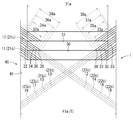
- a series of steps for cutting the work material 40 with each of the inserts 11 to 19 to form the groove 41 will be described with reference to FIG.
- the cutting edges 21c to 23c of the tips 11 to 19 cut the work material 40 in order.
- the tip saw 1 advances toward the work material 40 upward in FIG.
- the groove 41 is formed with a cutting width 41a having substantially the same length as the blade thickness T.
- the cutting edge 21c of the first insert 11 cuts the work material 40 to form a cutting edge line 30 horizontal to the cutting width direction of the groove 41.
- the cutting edges 22c and 23c of the second to ninth tips 12 to 19 cut the work material 40 in order.
- the cutting edge 22c of the second chip 12 cuts the left end portion of the groove 41 at a position sent from the first chip 11 to form the cutting edge line 32.
- the cutting edge line 32 is formed above the cutting edge line 30 in FIG.
- the cutting edge line 32 is inclined and extends at an inclination angle of 22 g (see FIG. 4) with respect to the cutting width direction of the groove 41.
- the cutting edge line 32 intersects the cutting edge line 30 and extends to the left end of the groove 41.
- the cutting edge 23c of the third chip 13 cuts the right end portion of the groove 41 at a position sent from the second chip 12 to form the cutting edge line 33.
- the cutting edge line 33 is formed above the cutting edge line 30 in FIG.
- the cutting edge line 33 extends in a direction inclined with an inclination angle of 23 g (see FIG. 4) with respect to the cutting width direction of the groove 41.
- the cutting edge line 33 intersects the cutting edge line 30 and extends to the right end of the groove 41.
- each cutting edge 22c of the 4th chip 14, the 6th chip 16, and the 8th chip 18 cuts the left end portion of the groove 41 to form the cutting edge lines 34, 36, and 38.
- the cutting edge lines 34, 36, and 38 are formed above the cutting edge line 32 at substantially equal intervals in FIG.
- the cutting edge lines 34, 36, and 38 extend in parallel with the cutting edge line 32.
- the cutting edge lines 34, 36, and 38 intersect the cutting edge line 30 and extend to the left end of the groove 41.
- the left end portion of the groove 41 becomes a cut surface of the substantially trapezoidal work material 40 having the cutting edge line 30, each cutting edge line 32, 34, 36, 38 and the left end of the groove 41 as the outer circumference, and chips are generated. It is cut out from the work material 40.
- Each cutting edge 23c of the 5th chip 15, the 7th chip 17, and the 9th chip 19 cuts the right end portion of the groove 41 to form the cutting edge lines 35, 37, 39.
- the cutting edge lines 35, 37, 39 are formed above the cutting edge line 33 at substantially equal intervals in FIG.
- the cutting edge lines 35, 37, 39 extend in parallel with the cutting edge line 33.
- the cutting edge lines 35, 37, 39 intersect the cutting edge line 30 and extend to the right end of the groove 41.
- a cut surface of a substantially trapezoidal work material 40 having a cutting edge line 30, each cutting edge line 33, 35, 37, 39 and the right end of the groove 41 as an outer circumference is formed, and chips are generated. It is cut out from the work material 40.
- the cutting edge 21c of the first chip 11 of the next chip group 10 cuts the work material 40 to form the cutting edge line 31.
- the cutting edge line 31 is formed above the cutting edge line 30 at a predetermined distance from the cutting edge line 30 in FIG.
- the cutting edge line 31 extends horizontally with the cutting width direction of the groove 41, and both left and right ends intersect with the cutting edge lines 38 and 39.
- the cut surface of the work material 40 having a substantially trapezoidal shape with the cutting edge lines 30, 31, 38, 39 as the outer circumference is formed, and chips are cut out from the work material 40.
- the cutting edge line length 31a of the cutting edge line 31 is the same length as the cutting edge line length of the cutting edge line 30 before the cutting edges 22c and 23c of the second to ninth chips 12 to 19 are cut.
- the cutting edge wire lengths 31a of the cutting edge wires 30 and 31 formed by the flat blade 21 are calculated by the following formula (1).
- the cutting edge lines 32, 34, 36, 38 formed by the left inclined blade 22 have cutting edge line lengths 32a, 34a, 36a, 38a, respectively.
- the cutting edge lines 33, 35, 37, 39 formed by the right-sloping blade 23 have cutting edge line lengths 33a, 35a, 37a, 39a, respectively.
- the total L of the cutting edge line lengths 32a to 39a of the left inclined blade 22 and the right inclined blade 23 per set of the chip group 10 is calculated by the following formula (2).
- L ⁇ K ⁇ (K-1) ⁇ Sz / 2 + (K-1) ⁇ H ⁇ / sinD
- K is the number of blades of the chip group 10.
- Reference numeral D is an inclination angle of 22 g for the left inclined blade 22 and an inclined angle of 23 g for the right inclined blade 23.
- T is the blade thickness (mm) of the tip saw 1.
- H is a height difference of 21 g between the left end 22d and the right end 23e with respect to the cutting edge 21c in the radial direction of the base metal 2.
- Sz is the feed amount (mm / blade) per blade.
- the inventor conducted an experiment to measure the cutting power (net cutting power) of a plurality of tip saws 1 having different cutting edge wire lengths of the flat blade 21 and the cutting edge wire lengths of the inclined blades 22 and 23.
- the number of blades of the tip group 10 the tilt angles 22 g and 23 g of the left tilt blade 22 and the right tilt blade 23, the height difference of the left tilt blade 22 and the right tilt blade 23 with respect to the flat blade 21 and the blade of the tip saw 1
- the thickness T and the feed amount Sz per blade were changed.
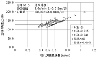
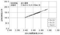
- the cutting edge line-related length A and the cutting power defined by the following equation (3) can be expressed by a linear function.
- the cutting edge line-related length A doubles the cutting edge line length of the flat blade 21 with respect to the left inclined blade 22 and the right inclined blade 23.
- the cutting power when the number of blades of the tip group 10 was changed was simulated.
- the tip group 10 has one flat blade 21 and has the same number of left-tilted blades 22 and right-tilted blades 23. Therefore, a simulation was performed for the case where the number of blades of the chip group 10 was 5, 7, 9, and 11.
- the blade thickness T (see FIG. 5) was 1.5 mm
- the feed amount Sz per blade was 0.016 mm / blade.
- the cutting power is determined by the cutting edge line-related length A when the flat blade 21 is weighted twice as shown in the equation (3) and the cutting edge line length per blade when not weighted. It turned out that there is a difference in the relationship with.
- the cutting power when the blade thickness T (see FIG. 5) of the tip saw 1 was changed was simulated. Simulations were performed for the cases where the blade thickness T was 1.0 mm, 1.5 mm, and 2.0 mm, respectively. In the simulation, the number of revolutions per minute was 5000, the total number of blades was 45, and the feed amount Sz per blade was 0.016 mm / blade. As a result of the simulation, the relationship of the linear function between the cutting edge line related length A and the cutting power was maintained even when the blade thickness T was changed.
- the cutting edge line-related length A tends to increase as the blade thickness T increases. Specifically, when the blade thickness T was 1.0 mm, the cutting edge line-related length A was approximately 0.4 to 0.6 mm. When the blade thickness T was 1.5 mm, the cutting edge line-related length A was approximately 0.5 to 0.8 mm. When the blade thickness T was 2.0 mm, the cutting edge line-related length A was approximately 0.6 to 1.0 mm.
- the total L of the cutting edge line lengths 31a of the flat blade 21 and the cutting edge line lengths 32a to 39a of the left inclined blade 22 and the right inclined blade 23 is per blade.
- the length is changed by changing the feed amount Sz of. Therefore, the length A related to the cutting edge line changes by changing the feed amount Sz per blade.
- the length A related to the cutting edge line when the feed amount Sz per blade is regarded as 0 mm / blade is defined.
- the total L of the cutting edge line length 31a of the flat blade 21 and the cutting edge line lengths 32a to 39a of the inclined blades 22 and 23 when the feed amount Sz per blade is regarded as 0 mm / blade is the following formula. It is obtained by (4) and equation (5).
- the cutting edge lines 32 and 33 are the cutting edge lines 32 to 39 formed by the left inclined blades 22 and the right inclined blades 23 of the second to ninth tips 12 to 19, respectively.
- the cutting edge wire lengths 30a, 32a, 33a are obtained from the assumed cutting edge wires 30, 32 to 39.
- the cutting power when the feed amount Sz per blade was changed was simulated. Simulations were performed for cases where the feed amount Sz per blade was 0 mm / blade, 0.016 mm / blade, and 0.04 mm / blade, respectively.
- the blade thickness T (see FIG. 5) was 1.5 mm
- the number of rotations per minute was 5000
- the total number of blades was 45.
- the relationship between the cutting edge line related length A and the cutting power is almost the same linear function between the case where the feed amount Sz per blade is 0.016 mm / blade and the case where it is 0.04 mm / blade. It was maintained.
- the feed amount Sz per blade When the feed amount Sz per blade is regarded as 0 mm / blade, the feed amount Sz per blade is 0.016 mm / blade, 0.04 mm / blade with the same cutting power and the cutting edge line related length A. was about 0.1 mm smaller. Within the range in which the feed amount Sz per blade was regarded as 0 mm / blade, the relationship of the linear function between the cutting edge line-related length A and the cutting power was maintained.
- Equation (6) was defined based on the results of the simulation shown in FIG.
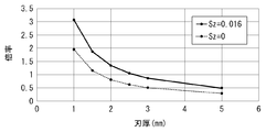
- the cutting edge wire length 31a of the flat blade 21 increases as the blade thickness T of the tip saw 1 increases. Therefore, as shown in FIG. 12, the magnification of the total L of the cutting edge line lengths 32a to 39a of the inclined blades 22 and 23 with respect to the cutting edge line length 31a of the flat blade 21 increases as the blade thickness T decreases. Become. The magnification of the total L of the cutting edge wire lengths 32a to 39a of the inclined blades 22 and 23 with respect to the cutting edge wire length 31a of the flat blade 21 increases as the feed amount Sz per blade increases.
- the inventor has set the blade thickness T to 1.5 mm and the feed amount Sz per blade to 0.016 mm / blade, and the total L of the cutting edge line lengths 32a to 39a of the inclined blades 22 and 23 is
- the following equation (7) is defined on the basis that the cutting edge wire length 31a of the flat blade 21 is twice or less.
- the feed amount Sz per blade is regarded as 0 mm / blade.
- the following equation (8) expresses the same relationship as the equation (7).
- Equation 7 Total L of cutting edge line lengths 32a to 39a of the left-tilted blade 22 and the right-tilted blade 23 of the tip group 10. ⁇ (cutting edge wire length 31a of flat blade 21-blade thickness T + 1.5 of tip saw 1) x 1.2 (Equation 8) Total of cutting edge line lengths 32a to 39a of all left inclined blades 22 and all right inclined blades 23 ⁇ (cutting edge line length 31a of flat blade 21 per piece-blade thickness T + 1 of tip saw 1.
- the total L of the cutting edge line lengths of the inclined blades per set of the tip group is the ratio of the cutting edge line length 51a of the flat blade to the cutting edge line length 51a of the flat blade.
- the number of blades K 5
- the inclination angle D 25 °
- the blade thickness T 1.5 (mm)
- the height difference H 0.2 (mm).
- the cutting edge wire length 51a of the cutting edge wire 51 of the flat blade when the feed amount Sz per blade is regarded as 0 mm / blade is 0.642 (mm) from the equation (4).
- the cutting power when the number of blades of the insert group 10 is changed as shown in FIG. I simulated it.
- a simulation was performed for the case where the number of blades of the chip group 10 was 5, 7, 9, 11, and 13.
- Two types of tip saws 1 having a blade thickness T of 1.3 mm and 1.5 mm were simulated.
- the inclination angles of 22 g and 23 g were set to 35 °, and the height difference of 21 g was set to 0.15 mm.
- the cutting power decreased as the number of braided blades increased.
- the effect of reducing cutting power is large in the range where the number of braided blades is small.
- the cutting power is reduced by 6 to 8%.
- the cutting power is reduced by 1 to 2%.
- the cutting power tends to decrease in the same manner when the blade thickness T is 1.3 mm and when the blade thickness T is 1.5 mm.
- the cutting power did not change or slightly increased as the number of braided blades increased.
- the cutting power is considered to be substantially unchanged or slightly increased as the total cutting edge line lengths of the inclined blades increase. From the above, it is considered that the cutting power can be reduced when the number of blades of the chip group 10 is 7 or more, and the effect of reducing the cutting power is preferably large when the number of blades is 7 to 11.
- the cutting power when the inclination angles 22 g and 23 g were changed as shown in FIG. 8 was simulated. ..
- the cutting power was simulated every 5 ° in the range of inclination angles 22g and 23g of 25 to 45 °, and every 10 ° in the range of 45 to 65 °.
- Two types of tip saws 1 having a blade thickness T of 1.3 mm and 1.5 mm were simulated. In the simulation, the number of blades of the chip group 10 was set to 5, and the height difference of 21 g was set to 0.15 mm.
- the cutting power decreased as the inclination angles 22g and 23g increased.
- the effect of reducing cutting power is large in the range where the inclination angles of 22 g and 23 g are small.
- the cutting power is reduced by about 2%.
- the cutting power is reduced by about 0.7%. The cutting power tends to decrease in the same manner when the blade thickness T is 1.3 mm and when the blade thickness T is 1.5 mm.
- the cutting power did not change or slightly increased as the inclination angles 22g and 23g increased.
- the inclination angles 22g and 23g are set to 65 ° or more, the left end 22d of the left inclination blade 22 and the right end 23e of the right inclination blade 23 may be chipped. Therefore, it is preferable that the inclination angles of 22 g and 23 g are 65 ° or less.
- the cutting power can be reduced when the inclination angles 22g and 23g are 30 ° or more, and the cutting power reduction effect is preferably large when the inclination angles 22g and 23g are 30 to 45 °.
- R chamfering, a flat portion of about 0.1 mm, C chamfering, etc. may be provided at the left end 22d and the right end 23e.
- the tip saw 1 has a disk-shaped base metal 2 as shown in FIGS. 1, 4, 5 and 15, and a plurality of first to ninth chips 11 to 19 joined to the outer periphery of the base metal 2. ..
- the plurality of first to ninth chips 11 to 19 have a plurality of flat blades 21, a plurality of left inclined blades 22, and a plurality of right inclined blades 23.
- the flat blade 21 includes a cutting edge 21c that is horizontal to the thickness direction of the base metal 2.
- the left-tilt blade 22 and the right-tilt blade 23 include cutting edges 22c and 23c that are inclined with respect to the thickness direction of the base metal 2.
- the length at which the cutting edges 21c, 22c, and 23c hit the work material 40 when cutting the work material 40 is the cutting edge line lengths 31a to 39a.
- the feed amount Sz per blade is regarded as 0 mm / blade, and the cutting edge line lengths 30a, 32a, 33a corresponding to the cutting edge line lengths 31a to 39a are obtained.
- the cutting edge line formed by the flat blade 21 of the first insert 11 first cutting the work material 40 is defined as the cutting edge line 30.
- the left-tilted blade 22 of the second tip 12 and the right-tilted blade 23 of the third tip 12 of the same tip group 10 cut the work material 40 immediately after cutting the flat blade 21 to form cutting edge lines 32 and 33. ..
- the cutting edge lines 32 and 33 are the cutting edge lines 32 to 39 formed by the left inclined blades 22 and the right inclined blades 23 of the second to ninth tips 12 to 19, respectively.
- the cutting edge wire lengths 30a, 32a, 33a are obtained from the assumed cutting edge wires 30, 32 to 39.
- the cutting edge wire lengths 30a, 32a, 33a are related as follows. Sum of cutting edge wire lengths 32a and 33a of a plurality of left-tilted blades 22 and right-tilted blades 23 ⁇ (cutting edge wire length 30a of flat blade 21 per piece-blade thickness T + 1.5 of tip saw 1) ⁇ plurality Number of flat blades 21 x 1.2 Meet.
- the left-tilted blade 22 and the right-tilted blade 23 shown in FIG. 4 have a role of smoothing the side surface of the groove 41 shown in FIG. 5, which is a cut surface. Therefore, the tip saw 1 preferably has a left inclined blade 22 and a right inclined blade 23.
- the inventor's sincere research shows that the cutting edge wire length 30a (31a) of the flat blade 21 has a greater influence on the cutting power than the cutting edge wire lengths 32a and 33a of the left inclined blade 22 and the right inclined blade 23. I found out by.
- This feature does not reduce the cutting edge line length 30a of the flat blade 21, but increases the cutting edge line length 30a of the flat blade 21 and increases the cutting edge line lengths 32a and 33a of the inclined blades 22 and 23.
- the cutting edge wire length 30a of the flat blade 21 shorter than the influence of the cutting edge wire length 30a, the cutting power can be made smaller than before.
- the tip saw 1 has a plurality of chip groups 10 including a disk-shaped base metal 2 and first to ninth chips 11 to 19 joined to the outer periphery of the base metal 2.
- the plurality of first to ninth chips 11 to 19 have a plurality of flat blades 21, a plurality of left inclined blades 22, and a plurality of right inclined blades 23.
- the flat blade 21 includes a cutting edge 21c that is horizontal to the thickness direction of the base metal 2.
- the left-tilt blade 22 and the right-tilt blade 23 include cutting blades 22c and 23c that are inclined with respect to the thickness direction of the base metal 2.
- the length at which the cutting edges 21c, 22c, and 23c hit the work material 40 when cutting the work material 40 is the cutting edge line lengths 31a to 39a.
- the sum of the cutting edge line lengths 32a to 39a of the plurality of left-tilted blades 22 and the right-tilting blade 23 is less than twice the total of the cutting edge line lengths 31a of the plurality of flat blades 21. Therefore, the sum of the cutting edge line lengths 32a to 39a of the plurality of left-inclined blades 22 and the right-inclined blade 23 is small. As a result, the cutting power can be made smaller than before.
- the blade thickness T is 1.0 to 2.0 mm, the cutting power can be reduced as compared with the conventional case. The effect is particularly remarkable when the blade thickness T is 1.5 mm.
- the tip saw 1 has a disk-shaped base metal 2 and a plurality of first to ninth chips 11 to 19 joined to the outer periphery of the base metal 2.
- the plurality of first to ninth chips 11 to 19 have a plurality of flat blades 21, a plurality of left inclined blades 22, and a plurality of right inclined blades 23.
- the flat blade 21 includes a cutting edge 21c that is horizontal to the thickness direction of the base metal 2.
- the left-tilt blade 22 and the right-tilt blade 23 include cutting edges 22c and 23c that are inclined with respect to the thickness direction of the base metal 2.
- the length at which the cutting edges 21c, 22c, and 23c hit the work material 40 when cutting the work material 40 is the cutting edge line lengths 31a to 39a.
- the feed amount Sz per blade is regarded as 0 mm / blade, and the cutting edge line lengths 30a, 32a, 33a corresponding to the cutting edge line lengths 31a to 39a are obtained.
- the cutting edge line formed by the flat blade 21 of the first insert 11 first cutting the work material 40 is defined as the cutting edge line 30.
- the left-tilted blade 22 of the second tip 12 and the right-tilted blade 23 of the third tip 12 of the same tip group 10 cut the work material 40 immediately after cutting the flat blade 21 to form cutting edge lines 32 and 33. ..
- the cutting edge lines 32 and 33 are the cutting edge lines 32 to 39 formed by the left inclined blades 22 and the right inclined blades 23 of the second to ninth tips 12 to 19, respectively.
- the cutting edge wire lengths 30a, 32a, 33a are obtained from the assumed cutting edge wires 30, 32 to 39.
- the cutting edge line related length A there is a correlation between the cutting edge line related length A and the cutting power. That is, it was found that the cutting power can be estimated from the cutting edge line-related length A.
- a plurality of flat blades 21, a plurality of left-sloping blades 22, and a right-sloping blade 23 are provided so that the cutting edge line-related length A satisfies the above relationship. As a result, the cutting edge line-related length A becomes smaller than before. Therefore, the cutting power can be made smaller than before.
- the plurality of first to ninth chips 11 to 19 have one flat blade 21 arranged in the circumferential direction of the base metal 2, and a total of six or more left-tilted blades 22 and right-tilted blades 22. It has a plurality of chip groups 10 including blades 23.
- the radial height difference between the flat blade 21 and the base metal 2 of the left inclined blade 22 or the right inclined blade 23 is 0.15 mm or less.
- the tilt angles 22g and 23g of the left tilt blade 22 and the right tilt blade 23 are 30 ° or more and less than 90 °.
- the sum of the cutting edge wire lengths 32a to 39a of the plurality of left-tilted blades 22 and the right-tilted blade 23 is not twice the sum of the cutting edge wire lengths 31a of the plurality of flat blades 21, and one flat blade 21 is used.
- a chip group 10 having a total of 6 or more left-tilted blades 22 and right-tilted blades 23 is formed.
- the cutting edge line length per left inclined blade 22 or right inclined blade 23 is small.
- the radial height difference between the left-tilted blade 22 and the right-tilted blade 23 with respect to the flat blade 21 in the radial direction is as small as 0.15 mm or less.
- the inclination angles 22g and 23g of the left inclination blade 22 and the right inclination blade 23 are large at 30 ° or more and less than 90 °.
- the cutting edge lines 32 to 39 of the left inclined blade 22 and the right inclined blade 23 intersect with the cutting edge lines 30 and 31 of the flat blade 21 at positions closer to the left and right ends of the groove 41. Therefore, the cutting edge line lengths 32a to 39a of the inclined blades 22 and 23 are smaller, and thus the cutting power is small.
- the left-tilted blade 22 or the right-tilted blade 23 shown in FIG. 4 has a smaller cutting edge line length, so that the left-tilted blade 22 and the right-tilted blade 23 have left and right ends of the groove 41 shown in FIG.
- the chips generated by cutting the blade become smaller. As a result, chips can be easily discharged from the left and right ends of the groove 41, and the cut surface of the work material 40 becomes smooth.
- the plurality of inclined blades include a plurality of left inclined blades 22 and a plurality of right inclined blades 23.
- the left inclined blade 22 and the right inclined blade 23 are arranged alternately.
- the left end 22d of the left inclined blade 22 is projected outward in the radial direction of the base metal 2 (see FIG. 1) when viewed from the front in the circumferential direction of the cutting blade 22c.
- the right end 23e of the right inclined blade 23 projects outward in the radial direction of the base metal 2. Therefore, the grooves 41 can be cut alternately on the left and right in a well-balanced manner.
- chips are generated alternately on the left and right sides of the groove 41. In other words, chips are generated at predetermined time intervals on the left and right sides of the groove 41. As a result, chips can be smoothly discharged from both the left and right sides of the groove 41.
- the tip group 10 has one flat blade 21 as described above.
- the chip group 10 may have two or more flat blades 21.
- the chip group 10 has four left-inclined blades 22 and four right-inclined blades 23 as described above.
- the number of the left inclined blade 22 and the right inclined blade 23 included in the chip group 10 may not be the same.
- the tip group 10 may be composed of only the flat blade 21 and the left inclined blade 22, or may be composed of only the flat blade 21 and the right inclined blade 23.
- the left inclined blade 22 and the right inclined blade 23 are alternately arranged in the circumferential direction of the base metal 2 as described above.
- the arrangement order of the flat blade 21, the left inclined blade 22 and the right inclined blade 23 in the circumferential direction may be appropriately changed, for example, the left inclined blade 22 is continuous in the circumferential direction of the base metal 2.
- the tip saw 1 has a plurality of sets of tip groups 10 in which the flat blade 21, the left inclined blade 22, and the right inclined blade 23 are arranged in the same circumferential direction.
- the flat blade 21, the left inclined blade 22, and the right inclined blade 23 may have a chip group 10 having different arrangement orders in the circumferential direction.
- the left tilt blade 22 and the right tilt blade 23 have tilt angles 22g and 23g having the same angle as described above.
- a plurality of different angles may be provided, for example, the inclination angles 22g and 23g of each left inclination blade 22 and each right inclination blade 23 are 30 °, 35 ° and 40 °.
- the radial heights of the cutting edge 21c or the left end 22d or the right end 23e of each of the chips 11 to 19 may be different.
- the outer diameter of the tip saw 1 and the interval (pitch) of each blade may be different so that the feed amount Sz per blade at the left end 22d and the right end 23e is the same.
- the shapes of the protrusions 4 and the tooth chambers 5 may be appropriately changed so that the blades have a predetermined interval.
- the cutting edge of the flat blade has been described in the present disclosure in a linear shape, it may be in a U shape, a ⁇ shape, or the like.
- a straight line having a short cutting edge line length is preferable.
- the amount of clams from the side surface of the base metal of the left end 21d of the left side surface 21h of the flat blade 21 and the amount of clams at the left end 23d of the left side surface 23h of the right inclined blade are the amount of clams at the left end of the left end surface 22h of the left inclined blade 22. It may be smaller.
- the amount of clams on the right end 21e of the flat blade 21 and the amount of clams on the right end 22e of the left inclined blade 22 may be smaller than the amount of clams on the right end 23e of the right inclined blade 22.
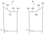
- the left-tilt blade 61 and the right-tilt blade 62 whose left-right width of the cutting blade is smaller than the blade thickness T are provided. Is also good.
- the left-tilted blade 61 has a cutting edge 61a that is inclined inward in the radial direction of the base metal 2 from the left end 61c to the right.
- the cutting edge 61a has the same inclination angle (sharpening angle) as the cutting edge 22c.
- the cutting edge 61a extends in the left-right direction to the cutting edge end 61d at the center of the left inclined blade 61.
- the left inclined blade 61 has a horizontal end portion 61b extending from the cutting edge end 61d to the right end 61e.
- the right-tilt blade 62 has a shape in which the left-tilt blade 61 is inverted left and right. That is, the right inclined blade 62 has a cutting edge 62a extending inwardly in the radial direction of the base metal 2 from the right end 62c to the central cutting edge end 62d, and a horizontal end extending from the cutting edge end 62d to the left end 62e. It has a part 62b.
- the left-tilt blade 61 and the right-tilt blade 62 also allow the cutting blades 61a and 62a to cut the left and right ends of the groove 41 (see FIG. 5) of the work material 40 to form a cutting edge line.
Landscapes
- Engineering & Computer Science (AREA)
- Mechanical Engineering (AREA)
- Life Sciences & Earth Sciences (AREA)
- Wood Science & Technology (AREA)
- Forests & Forestry (AREA)
- Sawing (AREA)
Priority Applications (4)
| Application Number | Priority Date | Filing Date | Title |
|---|---|---|---|
| US17/777,581 US12290869B2 (en) | 2019-12-19 | 2020-12-04 | Tipped saw blade |
| CN202080078194.0A CN114667195B (zh) | 2019-12-19 | 2020-12-04 | 圆锯片 |
| JP2021565471A JP7260671B2 (ja) | 2019-12-19 | 2020-12-04 | チップソー |
| EP20903911.4A EP4079433B1 (en) | 2019-12-19 | 2020-12-04 | Tip saw |
Applications Claiming Priority (2)
| Application Number | Priority Date | Filing Date | Title |
|---|---|---|---|
| JP2019-228921 | 2019-12-19 | ||
| JP2019228921 | 2019-12-19 |
Publications (1)
| Publication Number | Publication Date |
|---|---|
| WO2021124927A1 true WO2021124927A1 (ja) | 2021-06-24 |
Family
ID=76477318
Family Applications (1)
| Application Number | Title | Priority Date | Filing Date |
|---|---|---|---|
| PCT/JP2020/045213 Ceased WO2021124927A1 (ja) | 2019-12-19 | 2020-12-04 | チップソー |
Country Status (5)
| Country | Link |
|---|---|
| US (1) | US12290869B2 (https=) |
| EP (1) | EP4079433B1 (https=) |
| JP (1) | JP7260671B2 (https=) |
| CN (1) | CN114667195B (https=) |
| WO (1) | WO2021124927A1 (https=) |
Families Citing this family (2)
| Publication number | Priority date | Publication date | Assignee | Title |
|---|---|---|---|---|
| USD1037808S1 (en) | 2021-09-23 | 2024-08-06 | C.M.T. Utensili S.P.A. | Cutting disc |
| CN119347895A (zh) * | 2024-10-16 | 2025-01-24 | 杭州和源精密工具有限公司 | 一种加工硬杂木的锯片 |
Citations (10)
| Publication number | Priority date | Publication date | Assignee | Title |
|---|---|---|---|---|
| GB1151382A (en) * | 1967-03-22 | 1969-05-07 | James Charles Lee | Improvements in or relating to Saw Blades |
| JPS63169215U (https=) | 1987-04-21 | 1988-11-04 | ||
| JPH08187702A (ja) | 1995-01-13 | 1996-07-23 | Kanefusa Kk | 低騒音丸鋸 |
| JPH09290323A (ja) | 1996-04-26 | 1997-11-11 | Omi Kogyo Co Ltd | 切削工具 |
| JPH1080823A (ja) * | 1996-09-04 | 1998-03-31 | Tenryu Seikiyo Kk | 回転鋸のチップの構造 |
| JPH11277330A (ja) * | 1998-03-27 | 1999-10-12 | Kanex Hamono Kogyo Kk | 丸鋸刃 |
| JP3212951B2 (ja) | 1998-10-22 | 2001-09-25 | 兼房株式会社 | 分割切削型チップソー |
| JP3370166B2 (ja) | 1993-01-13 | 2003-01-27 | ヴイークス−ゼーゲンファブリーク・ウイルヘルム・ハー・クルマン | 基体と目振りされてない歯とを備えた鋸刃 |
| JP2004066400A (ja) * | 2002-08-07 | 2004-03-04 | Tenryu Saw Mfg Co Ltd | 回転鋸 |
| JP6163706B2 (ja) | 2011-05-06 | 2017-07-19 | ウィクス−サゲンファブリック ウィルヘルム エイチ.クルマン ゲーエムベーハー アンド カンパニー ケージー | 中空材及び形材を切断するための鋸刃 |
Family Cites Families (16)
| Publication number | Priority date | Publication date | Assignee | Title |
|---|---|---|---|---|
| JP2540470Y2 (ja) * | 1993-07-22 | 1997-07-02 | 天龍製鋸株式会社 | 金属切断用回転鋸 |
| JP3407831B2 (ja) * | 1994-11-23 | 2003-05-19 | 株式会社谷テック | 回転鋸 |
| JP2000254821A (ja) * | 1999-03-05 | 2000-09-19 | Tenryu Saw Mfg Co Ltd | 回転鋸 |
| DE10123752A1 (de) * | 2001-05-16 | 2002-11-28 | Ledermann & Co | Kreissägeblatt mit Wechsel-und Räumzähnen |
| JP4144863B2 (ja) * | 2003-01-31 | 2008-09-03 | 株式会社アライドマテリアル | 回転鋸による被削材の切断方法 |
| JP2005059124A (ja) * | 2003-08-08 | 2005-03-10 | Tenryu Saw Mfg Co Ltd | 回転鋸 |
| JP4420464B2 (ja) * | 2006-01-30 | 2010-02-24 | 株式会社谷テック | チップソー |
| US20080307941A1 (en) * | 2007-06-15 | 2008-12-18 | Freud America, Inc. | Saw blade tooth geometry for circular saw blade |
| JP2011020252A (ja) * | 2009-07-17 | 2011-02-03 | Trigger:Kk | チップソー |
| CN101758521B (zh) * | 2010-01-07 | 2012-05-09 | 宫电高周波设备(上海)有限公司 | 镶刃锯片 |
| JP6339764B2 (ja) * | 2013-02-25 | 2018-06-06 | 兼房株式会社 | 丸鋸 |
| CN203944927U (zh) * | 2014-06-18 | 2014-11-19 | 昆山兼房高科技刀具有限公司 | 圆锯片 |
| EP3530392B1 (en) * | 2016-10-18 | 2022-06-15 | Kanefusa Kabushiki Kaisha | Tipped circular saw blades |
| US11253935B2 (en) * | 2018-04-20 | 2022-02-22 | Kanefusa Kabushiki Kaisha | Segmented cutting type tipped saw blade |
| CN208451793U (zh) * | 2018-07-10 | 2019-02-01 | 杭州布镭德工具有限公司 | 一种锯片 |
| JP7305339B2 (ja) * | 2018-12-06 | 2023-07-10 | 天龍製鋸株式会社 | 回転鋸 |
-
2020
- 2020-12-04 CN CN202080078194.0A patent/CN114667195B/zh active Active
- 2020-12-04 US US17/777,581 patent/US12290869B2/en active Active
- 2020-12-04 EP EP20903911.4A patent/EP4079433B1/en active Active
- 2020-12-04 JP JP2021565471A patent/JP7260671B2/ja active Active
- 2020-12-04 WO PCT/JP2020/045213 patent/WO2021124927A1/ja not_active Ceased
Patent Citations (10)
| Publication number | Priority date | Publication date | Assignee | Title |
|---|---|---|---|---|
| GB1151382A (en) * | 1967-03-22 | 1969-05-07 | James Charles Lee | Improvements in or relating to Saw Blades |
| JPS63169215U (https=) | 1987-04-21 | 1988-11-04 | ||
| JP3370166B2 (ja) | 1993-01-13 | 2003-01-27 | ヴイークス−ゼーゲンファブリーク・ウイルヘルム・ハー・クルマン | 基体と目振りされてない歯とを備えた鋸刃 |
| JPH08187702A (ja) | 1995-01-13 | 1996-07-23 | Kanefusa Kk | 低騒音丸鋸 |
| JPH09290323A (ja) | 1996-04-26 | 1997-11-11 | Omi Kogyo Co Ltd | 切削工具 |
| JPH1080823A (ja) * | 1996-09-04 | 1998-03-31 | Tenryu Seikiyo Kk | 回転鋸のチップの構造 |
| JPH11277330A (ja) * | 1998-03-27 | 1999-10-12 | Kanex Hamono Kogyo Kk | 丸鋸刃 |
| JP3212951B2 (ja) | 1998-10-22 | 2001-09-25 | 兼房株式会社 | 分割切削型チップソー |
| JP2004066400A (ja) * | 2002-08-07 | 2004-03-04 | Tenryu Saw Mfg Co Ltd | 回転鋸 |
| JP6163706B2 (ja) | 2011-05-06 | 2017-07-19 | ウィクス−サゲンファブリック ウィルヘルム エイチ.クルマン ゲーエムベーハー アンド カンパニー ケージー | 中空材及び形材を切断するための鋸刃 |
Non-Patent Citations (1)
| Title |
|---|
| See also references of EP4079433A4 |
Also Published As
| Publication number | Publication date |
|---|---|
| EP4079433A1 (en) | 2022-10-26 |
| CN114667195B (zh) | 2023-11-14 |
| US20230020592A1 (en) | 2023-01-19 |
| JP7260671B2 (ja) | 2023-04-18 |
| CN114667195A (zh) | 2022-06-24 |
| JPWO2021124927A1 (https=) | 2021-06-24 |
| EP4079433B1 (en) | 2026-01-28 |
| US12290869B2 (en) | 2025-05-06 |
| EP4079433A4 (en) | 2024-01-17 |
Similar Documents
| Publication | Publication Date | Title |
|---|---|---|
| JP5722909B2 (ja) | 丸め成形されたノーズエンドミルの切削エッジの形状の最適化 | |
| JP5514208B2 (ja) | 面取りカッタ | |
| JP2004223642A (ja) | スクエアエンドミル | |
| WO2021124927A1 (ja) | チップソー | |
| JP3370166B2 (ja) | 基体と目振りされてない歯とを備えた鋸刃 | |
| EP2583788A1 (en) | Formed cutter manufacturing method and formed cutter grinding tool | |
| CN107405700A (zh) | 粗加工立铣刀 | |
| JP2018534164A5 (https=) | ||
| JP5946984B1 (ja) | 溝部の加工方法 | |
| US11253935B2 (en) | Segmented cutting type tipped saw blade | |
| JP5346827B2 (ja) | エンドミル | |
| JPWO2018110697A1 (ja) | 回転工具 | |
| JP7578680B2 (ja) | チップソー | |
| JP4561054B2 (ja) | ボールエンドミル | |
| JP2005131728A (ja) | 総形回転切削工具 | |
| CN224011305U (zh) | 一种球头铣刀 | |
| JPH06335813A (ja) | エンドミル | |
| JPS61178110A (ja) | ドリル | |
| JP7754561B1 (ja) | 回転工具 | |
| RU192176U1 (ru) | Фреза концевая для обработки труднообрабатываемых и титановых сплавов | |
| JPH06218616A (ja) | エンドミル | |
| CN212371269U (zh) | 一种加工螺旋轴用错齿刀盘 | |
| CN209792712U (zh) | 一种不等分弧形槽硬质合金铣刀 | |
| JPS59129611A (ja) | 切削工具 | |
| JPH06281B2 (ja) | ステツプ切削式フライスカツタ− |
Legal Events
| Date | Code | Title | Description |
|---|---|---|---|
| 121 | Ep: the epo has been informed by wipo that ep was designated in this application |
Ref document number: 20903911 Country of ref document: EP Kind code of ref document: A1 |
|
| ENP | Entry into the national phase |
Ref document number: 2021565471 Country of ref document: JP Kind code of ref document: A |
|
| NENP | Non-entry into the national phase |
Ref country code: DE |
|
| ENP | Entry into the national phase |
Ref document number: 2020903911 Country of ref document: EP Effective date: 20220719 |
|
| WWG | Wipo information: grant in national office |
Ref document number: 17777581 Country of ref document: US |
|
| WWG | Wipo information: grant in national office |
Ref document number: 2020903911 Country of ref document: EP |