EP4079433A1 - Tip saw - Google Patents
Tip saw Download PDFInfo
- Publication number
- EP4079433A1 EP4079433A1 EP20903911.4A EP20903911A EP4079433A1 EP 4079433 A1 EP4079433 A1 EP 4079433A1 EP 20903911 A EP20903911 A EP 20903911A EP 4079433 A1 EP4079433 A1 EP 4079433A1
- Authority
- EP
- European Patent Office
- Prior art keywords
- cutting
- cutting edge
- edge
- edges
- flat
- Prior art date
- Legal status (The legal status is an assumption and is not a legal conclusion. Google has not performed a legal analysis and makes no representation as to the accuracy of the status listed.)
- Pending
Links
- 239000010953 base metal Substances 0.000 claims abstract description 107
- 238000004088 simulation Methods 0.000 description 23
- 239000000463 material Substances 0.000 description 7
- 230000000694 effects Effects 0.000 description 5
- 229910000831 Steel Inorganic materials 0.000 description 4
- 238000012886 linear function Methods 0.000 description 4
- 239000010959 steel Substances 0.000 description 4
- 239000002023 wood Substances 0.000 description 4
- CWYNVVGOOAEACU-UHFFFAOYSA-N Fe2+ Chemical compound [Fe+2] CWYNVVGOOAEACU-UHFFFAOYSA-N 0.000 description 2
- 229910052782 aluminium Inorganic materials 0.000 description 2
- XAGFODPZIPBFFR-UHFFFAOYSA-N aluminium Chemical compound [Al] XAGFODPZIPBFFR-UHFFFAOYSA-N 0.000 description 2
- 239000011195 cermet Substances 0.000 description 2
- 239000002131 composite material Substances 0.000 description 2
- 230000007423 decrease Effects 0.000 description 2
- 230000003247 decreasing effect Effects 0.000 description 2
- 230000002349 favourable effect Effects 0.000 description 2
- 239000002184 metal Substances 0.000 description 2
- 229910052751 metal Inorganic materials 0.000 description 2
- 238000005303 weighing Methods 0.000 description 2
- 229910000838 Al alloy Inorganic materials 0.000 description 1
- 229910000975 Carbon steel Inorganic materials 0.000 description 1
- 229910001018 Cast iron Inorganic materials 0.000 description 1
- VYZAMTAEIAYCRO-UHFFFAOYSA-N Chromium Chemical compound [Cr] VYZAMTAEIAYCRO-UHFFFAOYSA-N 0.000 description 1
- RYGMFSIKBFXOCR-UHFFFAOYSA-N Copper Chemical compound [Cu] RYGMFSIKBFXOCR-UHFFFAOYSA-N 0.000 description 1
- 229910000881 Cu alloy Inorganic materials 0.000 description 1
- ZOKXTWBITQBERF-UHFFFAOYSA-N Molybdenum Chemical compound [Mo] ZOKXTWBITQBERF-UHFFFAOYSA-N 0.000 description 1
- 239000010962 carbon steel Substances 0.000 description 1
- 239000011248 coating agent Substances 0.000 description 1
- 238000000576 coating method Methods 0.000 description 1
- 239000010949 copper Substances 0.000 description 1
- 229910052802 copper Inorganic materials 0.000 description 1
- 238000013016 damping Methods 0.000 description 1
- 229910003460 diamond Inorganic materials 0.000 description 1
- 239000010432 diamond Substances 0.000 description 1
- 238000007599 discharging Methods 0.000 description 1
- 230000002708 enhancing effect Effects 0.000 description 1
- -1 for example Inorganic materials 0.000 description 1
- 238000003754 machining Methods 0.000 description 1
- 239000007769 metal material Substances 0.000 description 1
- 238000012986 modification Methods 0.000 description 1
- 230000004048 modification Effects 0.000 description 1
- 229910052750 molybdenum Inorganic materials 0.000 description 1
- 239000011733 molybdenum Substances 0.000 description 1
- 230000000149 penetrating effect Effects 0.000 description 1
- 239000011347 resin Substances 0.000 description 1
- 229920005989 resin Polymers 0.000 description 1
- 239000010935 stainless steel Substances 0.000 description 1
- 229910001220 stainless steel Inorganic materials 0.000 description 1
- 238000004381 surface treatment Methods 0.000 description 1
Images


Classifications
-
- B—PERFORMING OPERATIONS; TRANSPORTING
- B23—MACHINE TOOLS; METAL-WORKING NOT OTHERWISE PROVIDED FOR
- B23D—PLANING; SLOTTING; SHEARING; BROACHING; SAWING; FILING; SCRAPING; LIKE OPERATIONS FOR WORKING METAL BY REMOVING MATERIAL, NOT OTHERWISE PROVIDED FOR
- B23D61/00—Tools for sawing machines or sawing devices; Clamping devices for these tools
- B23D61/02—Circular saw blades
- B23D61/04—Circular saw blades with inserted saw teeth the teeth being individually inserted
-
- B—PERFORMING OPERATIONS; TRANSPORTING
- B27—WORKING OR PRESERVING WOOD OR SIMILAR MATERIAL; NAILING OR STAPLING MACHINES IN GENERAL
- B27B—SAWS FOR WOOD OR SIMILAR MATERIAL; COMPONENTS OR ACCESSORIES THEREFOR
- B27B33/00—Sawing tools for saw mills, sawing machines, or sawing devices
- B27B33/02—Structural design of saw blades or saw teeth
- B27B33/08—Circular saw blades
Definitions
- One embodiment of the present disclosure relates to a tipped saw blade with a plurality of tips joined at and around an outer periphery of a disc-shaped base metal.
- the tipped saw blade serves to cut a workpiece made of, for example, wood and wood-based materials, composite materials thereof, steel materials, and non-ferrous metal materials, such as aluminum.
- Tips of a tipped saw blade are joined at and around a base metal.
- Each tip has a rake face on a front side in a rotational direction and a cutting edge at an end edge of the rake face.
- Rotating the tipped saw blade about an axis extending through the center of the disc of the base metal causes the cutting edges of the tips to cut a workpiece.
- the plurality of tips repeatedly cut the workpiece to form a groove in the workpiece. As a result, the workpiece can be cut with the tipped saw blade.
- a segmented cutting type tipped saw blade has been known.
- a workpiece is divided in a cutting width direction to be cut by the cooperation of the plurality of tips.
- Segmented cutting type tipped saw blades that include tips having various different top end profiles are disclosed, for example, in JP3212951B , JP H08-187702A , JP H09-290323A , JP3370166B , JP6163706B , and JP S63-169215U .
- Various types of tips are aligned in the circumferential direction of the base metal and form groups of tips. A plurality of groups of tips are aligned along a circumferential edge of the base metal.
- Each of the tips cuts a different spot depending on each top end profile in the cutting width direction of the groove.
- three types of tips each having a different top end profile, may be assigned to cut each area of a groove divided into three sections in the cutting width direction.
- chips split in the cutting width direction are produced.
- the chips split in small pieces can be favorably discharged from the grooves. This results in a reduction of the entry of the chips between the tips and the workpiece, thereby enhancing the cutting efficiency.
- each of the tips of the segmented cutting type tipped saw blade has a small contact area with the groove, as each of the tips comes in contact with a predetermined area that is divided in the cutting width direction.
- the frictional force between the tips and the workpiece will thus be reduced. Accordingly, the cutting resistance is reduced and the required cutting power can be reduced.
- a surface of the workpiece that has been cut with the segmented cutting type tipped saw blade will be smooth, as the chips are favorably discharged and the cutting resistance is reduced.
- the tipped saw blade may be used for a rechargeable tipped saw cutter (electric circular saw). In this case, the consumption of the rechargeable battery can be reduced and the operable time until the next recharging can be extended. Further, the tipped saw blade may be used for a stationary tipped saw cutter (tipped saw cutting machine). In this case, the time required for cutting the workpiece may be shortened. Therefore, there has long been a need for a tipped saw blade having a small cutting resistance as well as having a small required cutting power.
- a tipped saw blade may include a disc-shaped base metal and a plurality of tips joined at and around an outer periphery of the base metal.
- the plurality of tips include a plurality of tips each with a flat edge and a plurality of tips each with a beveled edge.
- a flat edge includes a cutting edge that is parallel to a thickness direction of the base metal.
- a beveled edge includes a cutting edge that is inclined in the thickness direction of the base metal.
- a cutting edge line length is a length at which the cutting edge comes in contact with the workpiece when the workpiece is being cut.
- the cutting edge line length is determined on the idea that the flat edge cuts the workpiece first and each of the beveled edges cuts the workpiece immediately after a cutting of a corresponding flat edge.
- the cutting edge line length satisfies the following relationship: (the sum of cutting edge line lengths of the plurality of beveled edges) ⁇ [((the cutting edge line length of one flat edge) - (the kerf thickness of tipped saw blade) + 1.5 ) ⁇ (the number of the plurality of flat edges) ⁇ 1.2].
- the beveled edges serve to smoothen lateral surfaces of the groove, the groove defining a cut surface. Therefore, it is favorable that the tipped saw blade includes beveled edges.
- the cutting edge line length of the flat edges affect the cutting power more significantly than the cutting edge line lengths of the beveled edges. This feature is not intended to reduce the cutting edge line length of the flat edges. Instead there is the intention to increase the cutting edge line length of the flat edges and to reduce the cutting edge line length of each of the beveled edges. Adjusting the cutting edge line length of the flat edges has a greater influence on the cutting power. By adjusting the cutting edge line of the flat edges, the cutting power is reduced as compared with conventional products.
- the tipped saw blade may include a disc-shaped base metal and a plurality of tips joined at and around an outer periphery of the base metal.
- the plurality of tips include a plurality of tips each with a flat edges and a plurality of tips each with a beveled edge.
- Each of the flat edge includes a cutting edge that is parallel to the thickness direction of the base metal.
- Each of the beveled edges includes a cutting edge that is inclined with respect to the thickness direction of the base metal. The lengths where the cutting edges come in contact with the workpiece the workpiece is being cut are referred to as a cutting edge line length.
- the sum of the cutting edge line lengths of the plurality of beveled edges is less than or equal to two times the sum of the cutting edge line lengths of the plurality of flat edges. Therefore, the sum of the cutting edge line lengths of the plurality of beveled edges is smaller than that of conventional cases. Also, the sum of the cutting edge line lengths of the plurality of the beveled edges is less than or equal to two times the sum of the cutting edge line lengths of the plurality of flat edges. This allows the cutting power to be smaller than conventional cases.
- the tipped saw blade may include a disc-shaped base metal and a plurality of tips joined at and around an outer periphery of the base metal.
- the plurality of tips include a plurality of tips each having a flat edge and a plurality of tips each having a beveled edge.
- Each of the flat edges includes a cutting edge that is parallel to the thickness direction of the base metal.
- Each of the beveled edges includes a cutting edge that is inclined with respect to the thickness direction of the base metal. The lengths where the cutting edges come in contact with the workpiece while the workpiece is being cut are referred to as cutting edge line lengths.
- the cutting edge line lengths are determined with an assumption that the flat edge cuts the workpiece first and each of the beveled edges cuts the workpiece immediately after the flat edge cuts the workpiece and with the assumption that the feed rate per edge is Omm/edge.
- the plurality of flat edges and the plurality of beveled edges are provided such that the cutting edge line-related length A satisfies the above-relationship. As a result, the cutting edge line-related length A will be small. Therefore, the cutting power can be reduced.
- the tipped saw blade includes a plurality of groups of tips, each of which includes one flat edge and six or more beveled edges aligned in the circumferential direction of the base metal.
- the height difference between the flat edge and the beveled edges in the radial direction of the base metal is less than or equal to 0.15mm.
- An inclination angle of each beveled edge is greater than or equal to 30° and smaller than 90°.
- the groups of tips each include six or more pieces of beveled edges in total for every one flat edge.
- the sum of the cutting edge lengths of the plurality of left beveled edges is less than or equal to two times the sum of the cutting edge line lengths of the plurality of the flat edges.
- the cutting edge line length of each beveled edge is small.
- the height difference between the beveled edges with respect to the flat edge is small, such less than or equal to 0.15mm in the radial direction of the base metal.
- the inclination angle of each beveled edge is large, such as greater than or equal to 30° and less than 90°.
- the cutting edge lines of the beveled edges thus intersect the cutting edge line of the flat edge at the locations closer to the left and right ends of the cutting width direction. Therefore, the cutting edge line lengths of beveled edges are smaller, and the cutting power is thus small.
- Cutting chips generated by cutting the left and right ends of the groove with each of the beveled edges are reduced in size since each cutting edge line length of the beveled edge is reduced. This facilitates the discharge of the cutting chips from the left and right ends of the groove. As a result, a cut surface of the workpiece may be made to be smoother.
- the tipped saw blade may include a plurality of left beveled edges and a plurality of right beveled edges.
- the left beveled edges and the right beveled edges are alternately arranged.
- the left end of the left beveled edge projects radially outward of the base metal as seen from the front in the circumferential direction (rotation direction) of the cutting edges.
- the right end of the right beveled edge projects radially outward of the base metal. Therefore, the groove can be cut on the left and right sides alternately and in a well-balanced manner.
- the cutting chips are alternately generated on the left and right sides of the groove. In other words, the cutting chips are produced on the left and right sides of the groove at predetermined time intervals. This allows cutting chips to be smoothly discharged from the both left and right sides of the groove.
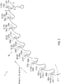
- a tipped saw blade 1 includes a disc-shaped base metal 2, a plurality of first to ninth tips 11 to 19 joined at and around an outer periphery of the base metal 2.
- the tipped saw blade 1 is rotatably attached to a cutting tool, such as, for example, a rechargeable battery type electric circular saw, a stationary tipped saw cutting machine, etc.
- a cutting tool such as, for example, a rechargeable battery type electric circular saw, a stationary tipped saw cutting machine, etc.
- Each of the tips 11-19 of the tipped saw blade 1 forms a groove in a workpiece as the base metal 2 is rotated.
- the tipped saw blade 1 ultimately cuts the workpiece.
- a workpiece may be made of, for example, wood, a wood-based material, a resin-based material, a composite material, or a steel material, such as carbon steel, rolled steel for general structures, chrome molybdenum steel, stainless steel, cast iron, etc.
- the workpiece may be made of, for example, a non-ferrous metal, such as, for example, aluminum, aluminum alloys, copper, or copper alloys.
- a substantially circular mounting hole 3 penetrating the base metal 2 in the plate thickness direction is formed in the center of the base metal 2.
- a rotary shaft of the cutting tool is inserted into the mounting hole 3, such that the tipped saw blade 1 is attached to the cutting tool. Rotating the rotary shaft of the cutting tool causes the tipped saw blade 1 to rotate about the center of the mounting hole 3 of the base metal 2 in a clockwise direction in FIG. 1 .
- a plurality of projections 4 projecting radially outward from the base metal 2 are provided at and around the circumferential edge of the base metal 2 at predetermined intervals.
- a gullet 5 that is recessed in the circumferential direction is formed between adjacent projections 4. Each gullet 5 is formed to have substantially the same shape.
- Each projection 4 has a tip seat 6 with a front end facing in the rotation direction of the tipped saw blade 1.
- Each tip seat 6 is chamfered in a rectangular shape.
- the first to ninth tips 11 to 19 are each bonded to a corresponding tip seat 6.
- the first to ninth tips 11 to 19 are arranged at constant intervals in the circumferential direction of the base metal 2.
- a plurality of meandering vibration damping slots 7 are formed in the base metal 2.
- the first to ninth tips 11 to 19 form a group of tips 10 lined up along the outer periphery of the base metal 2.
- the first tip 11, second tip 12, third tip 13, fourth end tip 14, fifth tip 15, sixth tip 16, seventh tip 17, eighth tip 18, and ninth tip 19 are arranged in this order from the front of the rotation direction of the tipped saw blade 1.
- Each of the tips 11 to 19 is joined at the base metal 2 in a posture with its rake face substantially oriented to the circumferential direction of the base metal 2.
- Each of the tips 11 to 19 may be made of, for example, a cemented carbide, cermet, or polycrystalline diamond.
- each of the tips 11 to 19 may be made of, for example, a cemented carbide or cermet with a surface treatment such as a coating, etc.
- the first tip 11 is a flat edge 21.
- the second, fourth, sixth, and eighth tips 12, 14, 16, 18 are left beveled edges 22.
- the third, fifth, seventh, and ninth tips 13, 15, 17, 19 are right beveled edges 23.
- each group of tips 10 is formed with the flat edge 21 located at the head in the circumferential direction, and the left beveled edges 22 and right beveled edges 23 arranged alternately in the circumferential direction of the base metal 2 behind the flat edge 21 in the circumferential direction.
- the flat edge 21 has a rake face 21a on its front side in the rotation direction of the tipped saw blade 1.
- the rake angle of the rake face 21a is about 15° with respect to a radial direction of the base metal 2.
- the flat edge 21 has a flank 21b on an outer side in the radial direction of the base metal 2.
- a cutting edge 21c is formed where the rake face 21a intersects the flank 21b. As shown in FIG. 3 , the cutting edge 21c extends horizontally with respect to the thickness direction of the base metal 2.
- the flat edge 21 has a left end 21d and a right end 21e.
- the left end 21d is located at a left front end as seen from the front side in the circumferential direction of the cutting edge 21c when the flat edge 21 is in a posture with the cutting edge 21c located at the top.
- the right end 21e is located at a right front end.
- the edge thickness 21f of the flat edge 21 corresponds to a distance between the left end 21d and the right end 21e.
- a distance in the thickness direction of the base metal 2 (kerf thickness T) from a left end 22d of the left beveled edge 22 to a right end 23e of the right beveled edge 23 may be, for example, 1 to 2mm when the outer diameter of the base metal 2 (see FIG. 1 ) is 100 to 255mm. This distance may preferably be 1.3mm to 1.5mm.
- the flat edge 21 includes a left side face 21h extending radially inward of the base metal 2 (see FIG. 1 ) from the left end 21d and a right side face 21i extending radial inward of the base metal 2 from the right end 21e.
- Both the left side face 21h and the right side face 21i have an inclination angle (radial clearance angle) toward the inside of the base metal 2 with respect to the radial direction of the base metal 2 of smaller than or equal to 0° to 2°, for example, 30'. This slight inclination reduces a contact area between the workpiece and the left side face 21h and the right side face 21i such that the cutting resistance is reduced.
- a smooth cut surface finish can be achieved.
- the left beveled edge 22 has a rake face 22a and a flank 22b, similar to the flat edge 21.
- the cutting edge 22c is formed where the rake face 22a intersects the flank 22b.
- the left beveled edge 22 includes a left end 22d and a right end 22e.
- the left end 22d is located on the left front end as seen from the front side in the circumferential direction of the cutting edge 22c when the left beveled edge 22 is in the posture where the cutting edge 22c is located on the top.
- the right end 22e is located at the right front end.
- the left end 22d projects further radially outward from the metal 2 than the right end 22e.
- the left end 22d is located radially outward of the base metal 2 by a height difference 21g from the cutting edge 21c of the flat edge 21 when joined to the base metal 2.
- the height difference 21g may be less than or equal to 0.15mm, for example 0.05 to 0.10mm.
- the cutting edge 22c has an inclination angle (sharpening angle) 22g in the thickness direction of the base metal 2 (see FIG. 1 ).
- the inclination angle 22g is greater than or equal to 30° and smaller than 90°.
- the inclination angle 22g is greater than or equal to 30°, smaller than or equal to 65°, for example, 30°, 35°, 40°, or 45°.
- the edge thickness 22f of the left beveled edge 22 corresponds the distance between the left end 22d and the right end 22e in the thickness direction of the base metal 2.
- the left beveled edge 22 includes a left side face 22h extending radially inward of the base metal 2 from the left end 22d and a right side face 22i extending radially inward of the base metal 2 from the right end 22e.
- the left side face 22h and the right side face 22i have an inclination angle (radial clearance angle) toward the inside of the base metal 2 with respect to the radial direction of the base metal 2 of smaller than or equal to 0° to 2°, for example, 30'.
- the right beveled edge 23 has a rake face 23a and a flank 23b, similar to the flat edge 21.
- the cutting edge 23c is formed where the rake face 23a intersects the flank 23b.
- the right beveled edge 23 has a left end 23d and a right end 23e.
- the left end 23d is located at the left front end as seen from the front side in the circumferential direction of the cutting edge 23c when the right beveled edge 23 is in a posture where the cutting edge 23c is located on the top.
- the right end 23e is located at a right front end.
- the right end 23e projects further radially outward from the base metal 2 than the left end 23d.
- the right end 23e is located radially outward of the base metal 2 by a height difference 21g from the cutting edge 21c of the flat edge 21 when joined to the base metal 2 (see FIG. 1 ).
- the height difference 21g may be less than or equal to 0.15mm, for example 0.05 to 0.1mm.
- the cutting edge 23c has an inclination angle 23g with respect to the thickness direction of the base metal 2 (see FIG. 1 ).
- the inclination angle 23g is greater than or equal to 30° and smaller than 90°.
- the inclination angle 23g is greater than or equal to 30° and smaller than or equal to 65°, for example, 30°, 35°, 40°, 45°.
- the edge thickness 23f of the right beveled edge 23c corresponds to a distance between the left end 23d and the right end 23e in the thickness direction of the base metal 2.
- the right beveled edge 23 has a left side face 23h extending radially inward of the base metal 2 from a left end 23d and a right side face 23i extending radially inward of the base metal 2 from a right end 23e.
- the left side face 23h and the right side face 23i have an inclination angle toward the inside of the base metal 2 with respect to the radial direction of the base metal 2 of smaller than or equal to 0° to 2°, for example, 30'.
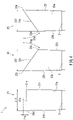
- a series of cutting a workpiece 40 with each of the tips 11 to 19 to form a groove 41 will be described with reference to FIG. 5 .
- the cutting edges 21c to 23c of each of the tips 11 to 19 cut the workpiece 40 in sequence as the tipped saw blade 1 rotates.
- the tipped saw blade 1 travels upward in FIG. 5 as the tipped saw blade 1 moves further into the workpiece 40.
- the groove 41 is formed with a cutting width 41a having substantially the same length as the kerf thickness T.
- the cutting edge 21c of the first tip 11 cuts the workpiece 40 to form a cutting edge line 30 parallel to the cutting width direction of the groove 41.
- each of the cutting edges 22c, 23c of the second to ninth tips 12 to 19 cuts the workpiece 40 in sequence while the tipped saw blade 1 proceeds as shown in FIG. 5 .
- the cutting edge 22c of the second tip 12 cuts the left end of the groove 41 in a proceeded position that is advanced further from the first tip 11 to form a cutting edge line 32.
- the cutting edge line 32 is formed on a side of the cutting edge line 30 further upward FIG. 5 .
- the cutting edge line 32 inclines and extends at an inclination angle 22g (see FIG. 4 ) with respect to the cutting width direction of the groove 41.
- the cutting edge line 32 intersects the cutting edge line 30 and extends up to the left end of the groove 41.
- the cutting edge 23c of the third tip 13 cuts the right end of the groove 41 to form a cutting edge line 33 in a position that is further advanced than the second tip 12.
- a cutting edge line 33 is formed on the upper side of FIG. 5 than the cutting edge line 30.
- the cutting edge line 33 extends in a direction inclined at an inclined angle 23g (see FIG. 4 ) with respect to the cutting width direction of the groove 41.
- the cutting edge line 33 intersects the cutting edge line 30 and extends up to the right end of the groove 41.
- each of the cutting edges 22c of the fourth tip 14, sixth tip 16, eighth tip 18 cuts the left end of the groove 41 to form cutting edge lines 34, 36, 38.
- the cutting edge lines 34, 36, 38 are formed on the upper side of the cutting edge line 32 in FIG. 5 at substantially equal intervals.
- the cutting edge lines 34, 36, 38 extend parallel to the cutting edge line 32.
- the cutting edge lines 34, 36, 38 intersect the cutting edge line 30 and extend up to the left end of the groove 41.
- the groove 41 has, at its left end, a cut surface in the workpiece 40 forming a substantially trapezoidal shape with the cutting edge line 30, each of the cutting edge lines 32, 34, 36, 38 and the left end of the groove 41 being as an outer periphery. Chips are cut out of the workpiece 40.
- Each of the cutting edges 23c of the fifth tip 15, seventh tip 17, and ninth tip 19 cuts the right end of the groove 41 to form the cutting edge lines 35, 37, 39.
- the cutting edge lines 35, 37, 39 are formed on the upper side of the cutting line 33 in FIG. 5 at substantially equal intervals.
- the cutting edge lines 35, 37, 39 extend parallel to the cutting edge line 33.
- the cutting edge lines 35, 37, 39 intersect the cutting edge line 30 and extend up to the right end of the groove 41.
- the groove 41 has, at its right end, a cut surface in the workpiece 40 having a substantially trapezoidal shape with the cutting edge line 30, each of the cutting edge lines 33, 35, 37, 39 and the right end of the outer periphery of the groove 41. Chips are cut out of the workpiece 40.
- the cutting edge 21c of the first tip 11 of a subsequent group of tips 10 cuts the workpiece 40 to form a cutting edge line 31.
- the cutting edge line 31 is formed on the upper side of the cutting edge line 30 in FIG. 5 by a predetermined interval from the cutting edge line 30.
- the cutting edge line 31 extends parallel to the cutting width direction of the groove 41 with both right and left ends intersecting the cutting edge lines 38, 39.
- the groove 41 has, at its center, a cut surface in the workpiece 40 having a substantially trapezoidal shape with the cutting edge lines 30, 31, 38, 39 forming an outer periphery, chips having been cut out of the workpiece 40.
- the cutting edge line length 31a of the cutting edge line 31 has the same length as the cutting edge line length of the cutting edge line 30 before being cut by each of the cutting edges 22c, 23c of the second to ninth tips 12 to 19.
- the cutting edge line length 31a of the cutting edge line is 30, 31 formed with the flat edge 21 may be determined using the following Equation (1).
- the cutting edge lines 32, 34, 36, 38 formed by the left beveled edge 22 have cutting edge line lengths 32a, 34a, 36a, 38a, respectively.
- the cutting edge lines 33, 35, 37, 39 formed by the right beveled edge 23 have cutting edge line lengths 33a, 35a, 37a, 39a, respectively.
- the sum L of the cutting edge line lengths 32a to 39a formed by the left beveled edges 22 and the right beveled edges 23 per each set of a group of tips 10 may be determined using the following Equation (2).
- the inventor has performed experiments to measure the cutting power (net cutting power) of a plurality of tipped saw blades 1, which have different cutting edge line lengths of the flat edge 21 and each of the beveled edges 22, 23.
- the number of edges per groups of the tips 10, the inclination angles 22g, 23g of the left beveled edges 22 and the right beveled edges 23, the height difference 21g between the left beveled edge 22 and the right beveled edge 23 with respect to the flat edge 21, the kerf thickness T of the tipped saw blade 1, and the feed rate per edge Sz were changed.
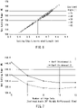
- the cutting edge line related length A which can be defined by Equation (3) below, and the cutting power can be represented substantially by a linear function.
- simulations were conducted to determine the cutting power when the number of edges per group of tips 10 is changed. It was given that the group of tips 10 includes one flat blade 21 and an equal number of left beveled edges 22 and the right beveled edges 23. Thus, simulations were conducted for the cases where the number of edges per group of tips 10 is 5, 7, 9, 11.
- the parameters were set such that the kerf thickness T (see FIG. 5 ) was 1.5mm and the feed rate per edge Sz was 0.016mm/edge.
- the simulation results show that there is a relationship between the cutting power when the cutting edge line-related length A is set to have twice as much weighting on the flat edge 21, as shown in Equation (3), as compared to not having any weighting.
- BC represents a tipped saw blade with the left beveled edges 22 and the right beveled edges 23 arranged alternately in the circumferential direction but no flat edges 21.
- simulations were conducted to determine how the cutting power changes when the kerf thickness T (see FIG. 5 ) of the tipped saw blade 1 was changed.
- the simulations were conducted with a kerf thickness T is 1.0mm, 1.5mm, and 2.0mm.
- the other parameters were set such that the number of rotations per minute was 5,000 times, the total number of edges was 45, and the feed rate per edge Sz was 0.016mm.
- the results of the simulations show that the linear functional relationship between the cutting edge line-related length A and the cutting power was maintained even when the kerf thickness T was changed.
- the cutting edge line-related length A tended to increase as the kerf thickness T increases.
- the cutting edge line-related length A was about 0.4 to 0.6mm.
- the cutting edge line-related length A was about 0.5 to 0.8mm.
- the cutting edge line-related length A was about 0.6 to 1.0mm.
- the sum L of the cutting edge line length 31a of the flat edge 21 and the cutting edge line lengths 32a to 39a of the left beveled edges 22 and the right beveled edges 23 vary when the feed rate per edge Sz is changed. Therefore, the cutting edge line-related length A varies when the feed rate per edge Sz is changed.
- the cutting edge line-related length A will be defined with the feed rate per edge Sz set to Omm/edge. This makes it possible to verify the relationship between the cutting edge line-related length A and the cutting power is not being affected by the feed rate per edge Sz, which is a machining condition.
- the sum L of the cutting edge line length 31a of the flat edge 21 and the cutting edge line lengths 32a to 39a of each of the beveled edges 22, 23 can be determined using the following Equation (4) and Equation (5) when the feed rate per edge Sz is set to Omm/edge.
- 31 a T ⁇ 2 ⁇ H ⁇ cosD / sinD
- L K ⁇ 1 ⁇ H / sinD
- the cutting edge lines 31 to 39 are assumed as follows when the feed rate per edge Sz is set to Omm/edge.
- the cutting edge line 30 is determined to be the cutting edge line formed the flat edge 21 of the first tip 11 when it is the first tip to cut the workpiece 40.
- the left beveled edge 22 of the second tip 12 and the right beveled edge 23 of the third tip 12 cut immediately after the flat edge 21 cut the workpiece. Thereby, the left beveled edge 22 and the right beveled edge 23 form the cutting edge lines 32, 33.
- These cutting edge lines 32, 33 are assumed to be the cutting edge lines 32 to 39 that are formed by the left beveled edges 22 and the right beveled edges 23 of the second to ninth tips 12 to 19, respectively.
- the cutting edge line lengths 30a, 32a, 33a are determined from the assumed cutting edge lines 30, 32 to 39.
- simulations were conducted to determine how the cutting power changes when the feed rate per edge Sz was changed.
- the simulations were conducted for the cases in which the feed rate per edge Sz was Omm/edge, 0.016mm/edge, and 0.04mm/edge.
- the other parameters were set such that the kerf thickness T (see FIG. 5 ) was 1.5mm, the number of rotations per minute was 5,000 times, and the total number of edges was 45.
- substantially the same linear functional relationship between the cutting edge line-related length A and the cutting power was maintained when the feed rate per edge Sz was between 0.016mm and 0.04mm/edge.
- the cutting edge line-related length A was about 0.1mm smaller at the same cutting power than when the feed rate per edge Sz was 0.016mm/edge and 0.04mm/edge.
- the linear functional relationship between the cutting edge line-related length A and the cutting power was substantially maintained.
- the inventor defined the following Equation (6) for the cutting edge line-related length A, with the feed rate per edge Sz set to 0mm/edge as a condition for the cutting power to be less than or equal to a predetermined value.
- the Equation (6) is defined based on the simulation results shown in FIG. 10 .
- the cutting edge line length 31a of the flat edge 21 increases as the kerf thickness T of the tipped saw blade 1 increases. Therefore, as shown in FIG. 12 , a ratio of the total sum L of the cutting edge line lengths 32a to 39a of each of the beveled edges 22, 23 with respect to the cutting edge line length 31a of the flat edge 21 increase as the kerf thickness T decreases. The ratio of the total sum L of the cutting edge line lengths 32a to 39a of each of the beveled edges 22, 23 with respect to the cutting edge line length 31a of the flat edge 21 increases as the feed rate per edge Sz increases.
- Equation (7) based on the fact that the total sum L of the cutting edge line lengths 32a to 39a of each of the beveled edges 22, 23 should be less than or equal to double of the cutting edge line length 31a of the flat edge 21 when the kerf thickness T is 1.5mm and the feed rate per edge Sz is 0.016mm/edge.
- the feed rate per edge Sz was set to Omm/edge.
- Equation (8) represents the same relationship as Equation (7).
- Equation 7 Total sum L of the cutting edge line lengths 32a to 39a of the left beveled edges 22 and the right beveled edges 23 in a group of tips 10) ⁇ ((cutting edge line length 31a of flat edge 21) - (kerf thickness T of tipped saw blade 1) + 1.5) ⁇ 1.2
- Equation 8 Total sum of cutting edge line lengths 32a to 39a of all left beveled edges and all right beveled edges 23) ⁇ ((cutting edge line length 31a of flat edge 21 per piece) - (kerf thickness T of tipped saw blade 1) + 1.5) ⁇ number of all flat edges 21 ⁇ 1.2.
- the ratio of the total sum L of the cutting edge line lengths of the beveled edges per each group of tips with respect to the cutting edge line length 51a of the flat edge for a conventional segmented cutting type tipped saw blade was greater than that of the tipped saw blade 1.
- the cutting edge line length 51a of the cutting edge line 51 of the flat edge is 0.642(mm) when the feed rate per edge Sz is set to Omm/edge.
- the total sum of the cutting edge line lengths 52a to 55a of the cutting edge lines 52 to 55 of the beveled edges is 1.893(mm).
- the results of the simulation show that the cutting power reduces as the number of edges per group increases in the range in of 5 to 11 edges per group, as shown in FIG. 7 .
- the reduction effect of the cutting power is particularly significant within the range in which the number of edges per group is small. For example when the number of edges per group is changed from 5 to 7, the cutting power reduces 6 to 8%.
- the cutting power may reduce 1 to 2% when the number of edges per group is change from 9 to 11.
- the cutting power shows a similar decreasing trend both when the kerf thickness T is 1.3 mm and when it is 1.5 mm.
- the cutting power remained generally unchanged or slightly increased as the number of edges per group increased.
- the cutting power is considered to remain generally unchanged or slightly increase when the number of edges per group is increased to more than 13, due to the increase in the sum of the cutting edge line lengths of the beveled edges. From the above, it was determined that the cutting power can be reduced when the number of edges per group of tips 10 is more than or equal to 7. It was also determined that the reduction effect of the cutting power is significant when the number of edges per group is preferably 7 to 11.
- the simulation result shows that the cutting power decreases as the inclination angles 22g, 23g increases in the range of 25 to 45°, as shown in FIG. 8 .
- the reduction effect of the cutting power is particularly significant when the inclination angles 22g, 23g are small. For example when the inclination angles 22g, 23g are changed from 25° to 30°, the cutting power is reduced by about 2%. For example, the cutting power may be reduced by about 0.7% when the inclination angles 22g, 23g are changed from 40° to 45°.
- the cutting power shows a similar decreasing trend both when the kerf thickness T is 1.3 mm and when it is 1.5 mm.
- the cutting power remains substantially unchanged or slightly changes as the inclination angles 22g, 23g increase within the range of 45° to 65°.
- the left end 22d of the left beveled edge 22 and the right end 23e of the right beveled edge 23 may be chipped when the inclination angles 22g, 23g are set to greater than 65°. Therefore, it is preferable to set the inclination angles 22g, 23g to be smaller than or equal to 65°. From the above, it was determined that the cutting power is reduced when the inclination angles 22g, 23g are greater than or equal to 30°, and that the reduction effect of the cutting power is significant when the inclination angles 22g, 23g are preferably 30° to 45°.
- the left end 22d and the right end 23e may be provided with an R-chamfering, a flat section of about 0.1mm, and/or a C-chamfering, etc.
- the tipped saw blade 1 includes a disc-shaped base metal 2 as shown in FIGS. 1 , 4 , 5 , and 15 and a plurality of first to ninth tips 11 to 19 joined at and around the outer periphery of the base metal 2.
- the plurality of first to ninth tips 11 to 19 include a plurality of flat edges 21, a plurality of left beveled edges 22, and a plurality of right beveled edges 23.
- Each flat edge 21 includes a cutting edge 21c that is parallel to the thickness direction of the base metal 2.
- the left beveled edge 22 and the right beveled edge 23 include cutting edges 22c, 23c that are inclined with respect to the thickness direction of the base metal 2.
- the lengths of the portions of the cutting edges 21c, 22c, 23c that come into contact with the workpiece 40 while cutting the workpiece 40 are referred to as the cutting edge line lengths 31a to 39a.
- the cutting edge line 30 is determined to be the cutting edge line first formed when the flat edge 21 of the first tip 11 cuts the workpiece 40.
- These cutting edge lines 32, 33 are assumed to be the cutting edge lines 32 to 39 that are formed by the left beveled edges 22 and the right beveled edges 23 of the second to ninth tips 12 to 19, respectively.
- the cutting edge line lengths 30a, 32a, 33a are determined from the assumed cutting edge lines 30, 32 to 39.
- the cutting edge line lengths 30a, 32a, 33a are set to satisfy the following relationship: The sum of cutting edge line lengths 32 a , 33 a of a plurality of left beveled edges 22 and right beveled edges 23 ⁇ the cutting edge line length 30 a of flat edge 21 per piece ⁇ the kerf thickness T of tipped saw blade 1 + 1.5 ⁇ number of edges of a plurality of flat edges 21 ⁇ 1.2
- the left beveled edge 22 and right beveled edge 23 shown in FIG. 4 serve to smoothen the lateral surfaces of the groove 41 in FIG. 5 , which define a cut surface. Therefore, it is preferable that the tipped saw blade 1 includes the left beveled edges 22 and right beveled edges 23.
- This feature is not to reduce the cutting edge line length 30a of the flat edge 21, but instead to increase the cutting edge line length 30a of the flat edge 21 and to reduce the cutting edge line lengths 32a, 33a of each of the beveled edges 22, 23.
- the tipped saw blade 1 includes a disc-shaped base metal 2 and a plurality of groups of tips 10, each group of tips 10 including a plurality of first to ninth tips 11 to 19 joined at and around an outer periphery of the base metal 2.
- the plurality of first to ninth tips 11 to 19 include a plurality of flat edges 21, a plurality of left beveled edges 22 and a plurality of right beveled edges 23.
- Each flat edge 21 includes a cutting edge 21c that is parallel to the thickness direction of the base metal 2.
- the left beveled edge 22 and the right beveled edge 23 include the cutting edges 22c, 23c that are inclined with respect to the thickness direction of the base metal 2.
- the lengths of the portion of the cutting edges 21c, 22c, 23c that come into contact with the workpiece 40 while cutting the workpiece 40 are referred to as the cutting edge line lengths 31a to 39a.
- the sum of the cutting edge line lengths 32a to 39a of the plurality of left beveled edges 22 and right beveled edges 23 is less than or equal to two times the sum of the cutting edge line lengths 31a of the plurality of flat edges 21. Therefore, the sum of the cutting edge line lengths 32a to 39a of the plurality of left beveled edges 22 and right beveled edges 23 is small. This allows the cutting power to be reduced as compared to conventional cases.
- the cutting power can be reduced as compared to conventional cases, especially if the kerf thickness T is in the range of 1.0mm to 2.0mm. In particular, this effect is significant when the kerf thickness T is 1.5mm.
- the tipped saw blade 1 includes a disc-shaped base metal 2 and a plurality of first to ninth tips 11 to 19 joined at and around an outer periphery of the base metal 2.
- the plurality of first to ninth tips 11 to 19 include a plurality of flat edges 21, a plurality of left beveled edges 22, and a plurality of right beveled edges 23.
- Each flat edge 21 includes a cutting edge 21c that is parallel to the thickness direction of the base metal 2.
- the left beveled edge 22 and right beveled edge 23 include the cutting edges 22c, 23c that are inclined with respect to the thickness direction of the base metal 2.
- the lengths of the portion of the cutting edges 21c, 22c, 23c that come into contact with the workpiece 40 while cutting the workpiece 40 are referred to as the cutting edge line lengths 31a to 39a.
- the cutting edge line lengths 30a, 32a, 33a corresponding to the cutting edge line lengths 31a to 39a, respectively will be determined when the feed rate per edge Sz is set to Omm/edge.
- the cutting edge line 30 is determined to be the cutting edge line formed when the flat edge 21 of the first tip 11 first cuts the workpiece 40.
- the left beveled edge 22 of the second tip 12 and the right beveled edge 23 of the third tip 12 in the same group of tips 10 cut the workpiece 40 immediately after the cutting of the flat edge 21 to form the cutting edge lines 32, 33.
- These cutting edge lines 32, 33 are assumed to be the cutting edge lines 32 to 39 that are formed by the left beveled edges 22 and the right beveled edges 23 of the second to ninth tips 12 to 19, respectively.
- the cutting edge line lengths 30a, 32a, 33a are determined from the assumed cutting edge lines 30, 32 to 39.
- the plurality of flat edges 21 and the plurality of left beveled edges 22 and right beveled edges 23 are provided such that the cutting edge line-related length A satisfies the above-relationship. As a result, the cutting edge line-related length A is reduced as compared with conventional products. Therefore, the cutting power can be reduced as compared with conventional products.
- the plurality of first to ninth tips 11 to 19 includes a plurality of groups of tips 10, each of which including one flat edge 21 and a total of six or more left beveled edges 22 and right beveled edges 23.
- the flat edge 21 and left beveled edges 22 and right beveled edges 23 are aligned in a circumferential direction of the base metal 2.
- the height difference between the flat edge 21 and the left beveled edges 22 or right beveled edges 23 in the radial direction of the base metal 2 is less than or equal to 0.15mm.
- the inclination angles 22g, 23a of the left beveled edge and right beveled edge 23 are greater than or equal to 30° and smaller than 90°.
- each of the groups of tips 10 includes at least six pieces of left beveled edges 22 and right beveled edges 23 and one flat edge 21.
- the sum of the cutting edge lengths 32a to 39a of the plurality of left beveled edges 22 and right beveled edges 23 is less than or equal to two times the sum of the cutting edge line lengths 31a of the plurality of the flat edges 21.
- the cutting edge line length of each individual left beveled edge 22 or right beveled edge 23 is small.
- the height difference between the left beveled edges 22 and right beveled edges 23 with respect to the flat edge 21 is small, such as less than or equal to 0.15mm in the radial direction of the base metal 2.
- the inclination angles 22g, 23a of the left beveled edges 22 and right beveled edges 23 are large, such as greater than or equal to 30° and less than 90°.
- the cutting edge lines 32 to 39 of the left beveled edges 22 and right beveled edges 23 thus intersect the cutting edge lines 30, 31 of the flat edge 21 at positions closer to the left and right ends of the groove 41. Therefore, the cutting edge line lengths 32a to 39a of each of the beveled edges 22, 23 are smaller. Thus the cutting power is also small.
- cutting chips generated by cutting the left and right ends of the groove 41 shown in FIG. 5 with the left beveled edges 22 and right beveled edges 23 are reduced in size. This is due in part to the cutting edge line length of the left beveled edges 22 and right beveled edges 23 per piece being reduced in size. This facilitates discharging the cutting chips from the left and right ends of the groove 41. This also results in a cut surface of the workpiece 40 being made smoother.
- the plurality of beveled edges includes the plurality of left beveled edges 22 and the plurality of right beveled edges 23.
- the left beveled edges 22 and right beveled edges 23 are alternately arranged.
- the left ends 22d of the left beveled edges 22 project radially outward from the base metal (see FIG. 1 ), as seen from the front in the circumferential direction of the cutting edges 22c.
- the right ends 23e of the right beveled edges 23 project radially outward of the base metal 2. Therefore, the left and right sides of the grooves 41 can be cut alternately in a well-balanced manner.
- the cutting chips are alternately generated on the left and right sides of the groove 41. In other words, the cutting chips are generated on the left and right sides of the groove 41, respectively at predetermined time intervals. This allows cutting chips to be smoothly discharged from the both the left and right sides of the groove 41.
- each group of tips 10 in the above embodiments includes one flat edge 21.
- each group of tips 10 may include two or more flat edges 21.
- each group of tips 10 includes four left beveled edges 22 and four right beveled edges 23.
- the number of left beveled edges 22 and right beveled edges 23 included in each group of tips 10 may not be the same.
- each group of tips 10 may include only the flat edge 21 and the left beveled edges 22 or only the flat edge 21 and the right beveled edges 23.
- each group of tips 10 includes the left beveled edges 22 and right beveled edges 23 arranged alternately at and around the base metal 2 in the circumferential direction.
- the circumferential arrangement order of the flat edges 21, left beveled edges 22, and right beveled edges 23 may be appropriately changed.
- the left beveled edges 22 may be continuously arranged in the circumferential direction of the base metal 2.
- the tipped saw blade 1 may include a plurality of sets of groups of tips 10, each of which includes the flat edge 21, left beveled edges 22, and right beveled edges 23 arranged in the same order in the circumferential direction.
- the tipped saw blade 1 may include groups of tips 10 each of which includes the flat edge 21, left beveled edges 22, and right beveled edges 23 arranged in a different order in the circumferential direction.
- the left beveled edges 22 and right beveled edges 23 have inclination angles 22g, 23 having the same angle.
- the inclination angles 22g, 23g of the left beveled edges 22 and right beveled edges 2 may have various different angles, such as 30°, 35°, or 40°.
- the radial heights of the cutting edge 21c, left end 22d, and/or right end 23e of each of the tips 11 to 19 may be different.
- An outer diameter of the tipped saw blade 1 or interval (pitch) between each edge may be made different, such that the feed rate per edge Sz of each edge at the left end 22d and right end 23e is the same.
- a profile of each projection 4 and each gullet 5 may be appropriately changed such that each edge has a predetermined interval.
- the flat edge has been described as having a linear cutting edge. However, it may instead have a U-shape or a V-shape. It is preferable that the cutting edge line length has a short linear-shape, as described.
- a projecting amount (setting amount) of the left end 21d of the left side face 21h of the flat edge 21 and a setting amount of the left end 23d of the left side face 23h of the right beveled edge may be made smaller than a setting amount of the left end of the left side face 22h of the left beveled edge 22.
- a setting amount of the right end 21e of the flat edge 21 and a setting amount of the right end 22e of the left beveled edge 22 may be made smaller than a setting amount of the right end 23e of the right beveled edge.
- the tipped saw blade 1 may be provided with, for example, left beveled edges 61 and right beveled edges 62.
- the left and right beveled edges 61, 62 may be formed such that cutting edges having a lateral width smaller than the kerf thickness T, as shown in FIG. 14 .
- the left beveled edge 61 has a cutting edge 61a that is inclined radially inward of the base metal 2 from a left end 61c to the right.
- the cutting edge 61a has the same inclination angle (sharpening angle) as the cutting edge 22c.
- the cutting edge 61a extends up to a cutting edge end 61d, which is in the center of the left beveled edge 61 in the left and right direction.
- the left beveled edge 61 includes a horizontal end portion 61b extending from the cutting edge end 61d to the right end 61e.
- the right beveled edge 62 has a profile corresponding to a mirror image of the left beveled edge 61 in the left-to-right direction. In other words, the right beveled edge 62 includes a cutting edge 62a that is inclined.
- the cutting edge 62a extends radially inward of the base metal 2 from the right end 62c to the cutting edge end 62d located in the center of the right beveled edge 62.
- the right beveled edge 62 also includes a horizontal end 62b extending from the cutting edge end 62d to the left end 62e. It is also possible to form cutting edge lines by cutting both the left and right ends of the groove 41 (see FIG. 5 ) of the workpiece 40 using the cutting edges 61a, 62 of the left beveled edges 61 and right beveled edges 62.
Abstract
Description
- One embodiment of the present disclosure relates to a tipped saw blade with a plurality of tips joined at and around an outer periphery of a disc-shaped base metal. The tipped saw blade serves to cut a workpiece made of, for example, wood and wood-based materials, composite materials thereof, steel materials, and non-ferrous metal materials, such as aluminum.
- Tips of a tipped saw blade, each of which has a substantially rectangular parallelepiped shape, are joined at and around a base metal. Each tip has a rake face on a front side in a rotational direction and a cutting edge at an end edge of the rake face. Rotating the tipped saw blade about an axis extending through the center of the disc of the base metal causes the cutting edges of the tips to cut a workpiece. The plurality of tips repeatedly cut the workpiece to form a groove in the workpiece. As a result, the workpiece can be cut with the tipped saw blade. A segmented cutting type tipped saw blade has been known. With a segmented cutting type tipped saw blade, a workpiece is divided in a cutting width direction to be cut by the cooperation of the plurality of tips. Segmented cutting type tipped saw blades that include tips having various different top end profiles are disclosed, for example, in
JP3212951B JP H08-187702A JP H09-290323A JP3370166B JP6163706B JP S63-169215U - Each of the tips cuts a different spot depending on each top end profile in the cutting width direction of the groove. For example, three types of tips, each having a different top end profile, may be assigned to cut each area of a groove divided into three sections in the cutting width direction. As a result, chips split in the cutting width direction are produced. The chips split in small pieces can be favorably discharged from the grooves. This results in a reduction of the entry of the chips between the tips and the workpiece, thereby enhancing the cutting efficiency. In addition, each of the tips of the segmented cutting type tipped saw blade has a small contact area with the groove, as each of the tips comes in contact with a predetermined area that is divided in the cutting width direction. The frictional force between the tips and the workpiece will thus be reduced. Accordingly, the cutting resistance is reduced and the required cutting power can be reduced. In addition, a surface of the workpiece that has been cut with the segmented cutting type tipped saw blade will be smooth, as the chips are favorably discharged and the cutting resistance is reduced.
- It is favorable for the tipped saw blade to have a small cutting resistance as well as a small driving power cutting requirement. For example, the tipped saw blade may be used for a rechargeable tipped saw cutter (electric circular saw). In this case, the consumption of the rechargeable battery can be reduced and the operable time until the next recharging can be extended. Further, the tipped saw blade may be used for a stationary tipped saw cutter (tipped saw cutting machine). In this case, the time required for cutting the workpiece may be shortened. Therefore, there has long been a need for a tipped saw blade having a small cutting resistance as well as having a small required cutting power.
- According to one aspect of the present disclosure, a tipped saw blade may include a disc-shaped base metal and a plurality of tips joined at and around an outer periphery of the base metal. The plurality of tips include a plurality of tips each with a flat edge and a plurality of tips each with a beveled edge. A flat edge includes a cutting edge that is parallel to a thickness direction of the base metal. A beveled edge includes a cutting edge that is inclined in the thickness direction of the base metal. A cutting edge line length is a length at which the cutting edge comes in contact with the workpiece when the workpiece is being cut. Given that the feed rate per edge is Omm/edge, the cutting edge line length is determined on the idea that the flat edge cuts the workpiece first and each of the beveled edges cuts the workpiece immediately after a cutting of a corresponding flat edge. The cutting edge line length satisfies the following relationship: (the sum of cutting edge line lengths of the plurality of beveled edges) ≤ [((the cutting edge line length of one flat edge) - (the kerf thickness of tipped saw blade) + 1.5 ) × (the number of the plurality of flat edges) × 1.2].
- The beveled edges serve to smoothen lateral surfaces of the groove, the groove defining a cut surface. Therefore, it is favorable that the tipped saw blade includes beveled edges. However, the inventor's sincere study further revealed that the cutting edge line length of the flat edges affect the cutting power more significantly than the cutting edge line lengths of the beveled edges. This feature is not intended to reduce the cutting edge line length of the flat edges. Instead there is the intention to increase the cutting edge line length of the flat edges and to reduce the cutting edge line length of each of the beveled edges. Adjusting the cutting edge line length of the flat edges has a greater influence on the cutting power. By adjusting the cutting edge line of the flat edges, the cutting power is reduced as compared with conventional products.
- According to another feature of the present disclosure, the tipped saw blade may include a disc-shaped base metal and a plurality of tips joined at and around an outer periphery of the base metal. The plurality of tips include a plurality of tips each with a flat edges and a plurality of tips each with a beveled edge. Each of the flat edge includes a cutting edge that is parallel to the thickness direction of the base metal. Each of the beveled edges includes a cutting edge that is inclined with respect to the thickness direction of the base metal. The lengths where the cutting edges come in contact with the workpiece the workpiece is being cut are referred to as a cutting edge line length. The sum of the cutting edge line lengths of the plurality of beveled edges is less than or equal to two times the sum of the cutting edge line lengths of the plurality of flat edges. Therefore, the sum of the cutting edge line lengths of the plurality of beveled edges is smaller than that of conventional cases. Also, the sum of the cutting edge line lengths of the plurality of the beveled edges is less than or equal to two times the sum of the cutting edge line lengths of the plurality of flat edges. This allows the cutting power to be smaller than conventional cases.
- According to another aspect of the present disclosure, the tipped saw blade may include a disc-shaped base metal and a plurality of tips joined at and around an outer periphery of the base metal. The plurality of tips include a plurality of tips each having a flat edge and a plurality of tips each having a beveled edge. Each of the flat edges includes a cutting edge that is parallel to the thickness direction of the base metal. Each of the beveled edges includes a cutting edge that is inclined with respect to the thickness direction of the base metal. The lengths where the cutting edges come in contact with the workpiece while the workpiece is being cut are referred to as cutting edge line lengths. The cutting edge line lengths are determined with an assumption that the flat edge cuts the workpiece first and each of the beveled edges cuts the workpiece immediately after the flat edge cuts the workpiece and with the assumption that the feed rate per edge is Omm/edge. The cutting edge line lengths satisfy the following relationship:

- The inventor's sincere study has revealed that there is a correlation between cutting edge line-related length A and the cutting power. In other words, it was found that the cutting power could be estimated from the cutting edge line-related length A. The plurality of flat edges and the plurality of beveled edges are provided such that the cutting edge line-related length A satisfies the above-relationship. As a result, the cutting edge line-related length A will be small. Therefore, the cutting power can be reduced.
- According to another aspect of the present disclosure, the tipped saw blade includes a plurality of groups of tips, each of which includes one flat edge and six or more beveled edges aligned in the circumferential direction of the base metal. The height difference between the flat edge and the beveled edges in the radial direction of the base metal is less than or equal to 0.15mm. An inclination angle of each beveled edge is greater than or equal to 30° and smaller than 90°.
- Therefore, the groups of tips each include six or more pieces of beveled edges in total for every one flat edge. The sum of the cutting edge lengths of the plurality of left beveled edges is less than or equal to two times the sum of the cutting edge line lengths of the plurality of the flat edges. As a result, the cutting edge line length of each beveled edge is small. In addition, the height difference between the beveled edges with respect to the flat edge is small, such less than or equal to 0.15mm in the radial direction of the base metal. In addition, the inclination angle of each beveled edge is large, such as greater than or equal to 30° and less than 90°. The cutting edge lines of the beveled edges thus intersect the cutting edge line of the flat edge at the locations closer to the left and right ends of the cutting width direction. Therefore, the cutting edge line lengths of beveled edges are smaller, and the cutting power is thus small. Cutting chips generated by cutting the left and right ends of the groove with each of the beveled edges are reduced in size since each cutting edge line length of the beveled edge is reduced. This facilitates the discharge of the cutting chips from the left and right ends of the groove. As a result, a cut surface of the workpiece may be made to be smoother.
- According to another aspect of the present disclosure, the tipped saw blade may include a plurality of left beveled edges and a plurality of right beveled edges. The left beveled edges and the right beveled edges are alternately arranged. The left end of the left beveled edge projects radially outward of the base metal as seen from the front in the circumferential direction (rotation direction) of the cutting edges. The right end of the right beveled edge projects radially outward of the base metal. Therefore, the groove can be cut on the left and right sides alternately and in a well-balanced manner. In addition, the cutting chips are alternately generated on the left and right sides of the groove. In other words, the cutting chips are produced on the left and right sides of the groove at predetermined time intervals. This allows cutting chips to be smoothly discharged from the both left and right sides of the groove.
-
-
FIG. 1 is a front view of a tipped saw blade according to a present embodiment. -
FIG. 2 is an enlarged front view of a part II inFIG. 1 . -
FIG. 3 is a view of each of tip in one group of tips of a tipped saw blade as seen in a circumferential direction of a base metal. -
FIG. 4 is an enlarged view of a flat edge and beveled edges of the tipped saw blade as seen in the circumferential direction of the base metal. -
FIG. 5 is a view of a cutting edge line of each tip and a workpiece as seen in the circumferential direction taking a feed material into account. -
FIG. 6 is a graph illustrating a relationship between a cutting edge line-related length and a cutting power. -
FIG. 7 is a graph illustrating a relationship between the number of edges per group of tips and the cutting power. -
FIG. 8 is a graph illustrating a relationship between inclination angles of the beveled edges and the cutting power. -
FIG. 9 is a graph illustrating the relationship between a cutting edge line length per edge, a cutting edge line-related length, and the cutting power. -
FIG. 10 is a graph illustrating a relationship between the cutting edge line-related length and the cutting power when a feed rate per edge is changed. -
FIG. 11 is a graph illustrating a relationship between the cutting edge line-related length and the cutting power when the kerf thickness is changed. -
FIG. 12 is a graph illustrating a relationship between a magnification of the total sum of the cutting edge line lengths of the beveled edges with respect to the total sum of the cutting edge line lengths of the flat edges and the kerf thickness. -
FIG. 13 is a view of the cutting edge lines of a conventional segmented cutting type tipped saw blade and a workpiece as seen in the circumferential direction and taking a feed material into account. -
FIG. 14 is a view of a modified example of beveled edges as seen in the circumferential direction of the base metal. -
FIG. 15 is a view of cutting edge lines of each of the tips and a workpiece as seen in the circumferential direction. - An exemplary embodiment of the present disclosure will be described with reference to
FIGS. 1 to 12 and15 . As shown inFIG. 1 , a tippedsaw blade 1 includes a disc-shapedbase metal 2, a plurality of first toninth tips 11 to 19 joined at and around an outer periphery of thebase metal 2. The tipped sawblade 1 is rotatably attached to a cutting tool, such as, for example, a rechargeable battery type electric circular saw, a stationary tipped saw cutting machine, etc. Each of the tips 11-19 of the tipped sawblade 1 forms a groove in a workpiece as thebase metal 2 is rotated. The tipped sawblade 1 ultimately cuts the workpiece. A workpiece may be made of, for example, wood, a wood-based material, a resin-based material, a composite material, or a steel material, such as carbon steel, rolled steel for general structures, chrome molybdenum steel, stainless steel, cast iron, etc. Alternatively, the workpiece may be made of, for example, a non-ferrous metal, such as, for example, aluminum, aluminum alloys, copper, or copper alloys. - As shown in
FIG. 1 , a substantiallycircular mounting hole 3 penetrating thebase metal 2 in the plate thickness direction is formed in the center of thebase metal 2. A rotary shaft of the cutting tool is inserted into the mountinghole 3, such that the tipped sawblade 1 is attached to the cutting tool. Rotating the rotary shaft of the cutting tool causes the tipped sawblade 1 to rotate about the center of the mountinghole 3 of thebase metal 2 in a clockwise direction inFIG. 1 . A plurality ofprojections 4 projecting radially outward from thebase metal 2 are provided at and around the circumferential edge of thebase metal 2 at predetermined intervals. Agullet 5 that is recessed in the circumferential direction is formed betweenadjacent projections 4. Eachgullet 5 is formed to have substantially the same shape. Eachprojection 4 has atip seat 6 with a front end facing in the rotation direction of the tipped sawblade 1. Eachtip seat 6 is chamfered in a rectangular shape. The first toninth tips 11 to 19 are each bonded to acorresponding tip seat 6. The first toninth tips 11 to 19 are arranged at constant intervals in the circumferential direction of thebase metal 2. A plurality of meanderingvibration damping slots 7 are formed in thebase metal 2. - As shown in
FIG 2 , the first toninth tips 11 to 19 form a group oftips 10 lined up along the outer periphery of thebase metal 2. Thefirst tip 11,second tip 12,third tip 13,fourth end tip 14,fifth tip 15,sixth tip 16,seventh tip 17,eighth tip 18, andninth tip 19 are arranged in this order from the front of the rotation direction of the tipped sawblade 1. Each of thetips 11 to 19 is joined at thebase metal 2 in a posture with its rake face substantially oriented to the circumferential direction of thebase metal 2. Each of thetips 11 to 19 may be made of, for example, a cemented carbide, cermet, or polycrystalline diamond. Alternatively, each of thetips 11 to 19 may be made of, for example, a cemented carbide or cermet with a surface treatment such as a coating, etc. - As shown in
FIG. 3 , thefirst tip 11 is aflat edge 21. The second, fourth, sixth, andeighth tips ninth tips tips 10 is formed with theflat edge 21 located at the head in the circumferential direction, and the leftbeveled edges 22 and rightbeveled edges 23 arranged alternately in the circumferential direction of thebase metal 2 behind theflat edge 21 in the circumferential direction. - As shown in
FIG. 2 , theflat edge 21 has arake face 21a on its front side in the rotation direction of the tipped sawblade 1. The rake angle of therake face 21a is about 15° with respect to a radial direction of thebase metal 2. Theflat edge 21 has aflank 21b on an outer side in the radial direction of thebase metal 2. Acutting edge 21c is formed where therake face 21a intersects theflank 21b. As shown inFIG. 3 , thecutting edge 21c extends horizontally with respect to the thickness direction of thebase metal 2. - As shown in
FIG. 4 , theflat edge 21 has aleft end 21d and aright end 21e. Theleft end 21d is located at a left front end as seen from the front side in the circumferential direction of thecutting edge 21c when theflat edge 21 is in a posture with thecutting edge 21c located at the top. Theright end 21e is located at a right front end. Theedge thickness 21f of theflat edge 21 corresponds to a distance between theleft end 21d and theright end 21e. A distance in the thickness direction of the base metal 2 (kerf thickness T) from aleft end 22d of the leftbeveled edge 22 to aright end 23e of the rightbeveled edge 23 may be, for example, 1 to 2mm when the outer diameter of the base metal 2 (seeFIG. 1 ) is 100 to 255mm. This distance may preferably be 1.3mm to 1.5mm. - As shown in
FIG. 4 , theflat edge 21 includes aleft side face 21h extending radially inward of the base metal 2 (seeFIG. 1 ) from theleft end 21d and a right side face 21i extending radial inward of thebase metal 2 from theright end 21e. Both theleft side face 21h and the right side face 21i have an inclination angle (radial clearance angle) toward the inside of thebase metal 2 with respect to the radial direction of thebase metal 2 of smaller than or equal to 0° to 2°, for example, 30'. This slight inclination reduces a contact area between the workpiece and theleft side face 21h and the right side face 21i such that the cutting resistance is reduced. Furthermore, since theleft side face 21h and right side face 21i are inclined to such an extent that they do not project too far from the cut surface of the workpiece, a smooth cut surface finish can be achieved. - As shown in
FIGS. 2 and4 , the leftbeveled edge 22 has arake face 22a and aflank 22b, similar to theflat edge 21. Thecutting edge 22c is formed where therake face 22a intersects theflank 22b. The leftbeveled edge 22 includes aleft end 22d and aright end 22e. Theleft end 22d is located on the left front end as seen from the front side in the circumferential direction of thecutting edge 22c when the leftbeveled edge 22 is in the posture where thecutting edge 22c is located on the top. Theright end 22e is located at the right front end. Theleft end 22d projects further radially outward from themetal 2 than theright end 22e. Theleft end 22d is located radially outward of thebase metal 2 by aheight difference 21g from thecutting edge 21c of theflat edge 21 when joined to thebase metal 2. Theheight difference 21g may be less than or equal to 0.15mm, for example 0.05 to 0.10mm. - As shown in
FIG. 4 , thecutting edge 22c has an inclination angle (sharpening angle) 22g in the thickness direction of the base metal 2 (seeFIG. 1 ). Theinclination angle 22g is greater than or equal to 30° and smaller than 90°. Preferably, theinclination angle 22g is greater than or equal to 30°, smaller than or equal to 65°, for example, 30°, 35°, 40°, or 45°. Theedge thickness 22f of the leftbeveled edge 22 corresponds the distance between theleft end 22d and theright end 22e in the thickness direction of thebase metal 2. The leftbeveled edge 22 includes aleft side face 22h extending radially inward of thebase metal 2 from theleft end 22d and aright side face 22i extending radially inward of thebase metal 2 from theright end 22e. Theleft side face 22h and theright side face 22i have an inclination angle (radial clearance angle) toward the inside of thebase metal 2 with respect to the radial direction of thebase metal 2 of smaller than or equal to 0° to 2°, for example, 30'. - As shown in
FIGS. 2 and4 , the rightbeveled edge 23 has arake face 23a and aflank 23b, similar to theflat edge 21. Thecutting edge 23c is formed where therake face 23a intersects theflank 23b. The rightbeveled edge 23 has aleft end 23d and aright end 23e. Theleft end 23d is located at the left front end as seen from the front side in the circumferential direction of thecutting edge 23c when the rightbeveled edge 23 is in a posture where thecutting edge 23c is located on the top. Theright end 23e is located at a right front end. Theright end 23e projects further radially outward from thebase metal 2 than theleft end 23d. Theright end 23e is located radially outward of thebase metal 2 by aheight difference 21g from thecutting edge 21c of theflat edge 21 when joined to the base metal 2 (seeFIG. 1 ). Theheight difference 21g may be less than or equal to 0.15mm, for example 0.05 to 0.1mm. - As shown in
FIG. 4 , thecutting edge 23c has aninclination angle 23g with respect to the thickness direction of the base metal 2 (seeFIG. 1 ). Theinclination angle 23g is greater than or equal to 30° and smaller than 90°. Preferably, theinclination angle 23g is greater than or equal to 30° and smaller than or equal to 65°, for example, 30°, 35°, 40°, 45°. Theedge thickness 23f of the rightbeveled edge 23c corresponds to a distance between theleft end 23d and theright end 23e in the thickness direction of thebase metal 2. The rightbeveled edge 23 has aleft side face 23h extending radially inward of thebase metal 2 from aleft end 23d and aright side face 23i extending radially inward of thebase metal 2 from aright end 23e. Theleft side face 23h and theright side face 23i have an inclination angle toward the inside of thebase metal 2 with respect to the radial direction of thebase metal 2 of smaller than or equal to 0° to 2°, for example, 30'. - A series of cutting a
workpiece 40 with each of thetips 11 to 19 to form agroove 41 will be described with reference toFIG. 5 . The cutting edges 21c to 23c of each of thetips 11 to 19 cut theworkpiece 40 in sequence as the tipped sawblade 1 rotates. The tipped sawblade 1 travels upward inFIG. 5 as the tipped sawblade 1 moves further into theworkpiece 40. Thegroove 41 is formed with acutting width 41a having substantially the same length as the kerf thickness T. Thecutting edge 21c of thefirst tip 11 cuts theworkpiece 40 to form acutting edge line 30 parallel to the cutting width direction of thegroove 41. - As shown in
FIG. 5 , each of thecutting edges ninth tips 12 to 19 cuts theworkpiece 40 in sequence while the tipped sawblade 1 proceeds as shown inFIG. 5 . Thecutting edge 22c of thesecond tip 12 cuts the left end of thegroove 41 in a proceeded position that is advanced further from thefirst tip 11 to form acutting edge line 32. Thecutting edge line 32 is formed on a side of thecutting edge line 30 further upwardFIG. 5 . Thecutting edge line 32 inclines and extends at aninclination angle 22g (seeFIG. 4 ) with respect to the cutting width direction of thegroove 41. Thecutting edge line 32 intersects thecutting edge line 30 and extends up to the left end of thegroove 41. Thecutting edge 23c of thethird tip 13 cuts the right end of thegroove 41 to form acutting edge line 33 in a position that is further advanced than thesecond tip 12. Acutting edge line 33 is formed on the upper side ofFIG. 5 than thecutting edge line 30. Thecutting edge line 33 extends in a direction inclined at aninclined angle 23g (seeFIG. 4 ) with respect to the cutting width direction of thegroove 41. Thecutting edge line 33 intersects thecutting edge line 30 and extends up to the right end of thegroove 41. - As shown in
FIG. 5 , each of thecutting edges 22c of thefourth tip 14,sixth tip 16,eighth tip 18 cuts the left end of thegroove 41 to form cuttingedge lines cutting edge lines cutting edge line 32 inFIG. 5 at substantially equal intervals. Thecutting edge lines cutting edge line 32. Thecutting edge lines cutting edge line 30 and extend up to the left end of thegroove 41. As a result, thegroove 41 has, at its left end, a cut surface in theworkpiece 40 forming a substantially trapezoidal shape with thecutting edge line 30, each of thecutting edge lines groove 41 being as an outer periphery. Chips are cut out of theworkpiece 40. - Each of the
cutting edges 23c of thefifth tip 15,seventh tip 17, andninth tip 19 cuts the right end of thegroove 41 to form thecutting edge lines cutting edge lines line 33 inFIG. 5 at substantially equal intervals. Thecutting edge lines cutting edge line 33. Thecutting edge lines cutting edge line 30 and extend up to the right end of thegroove 41. As a result, thegroove 41 has, at its right end, a cut surface in theworkpiece 40 having a substantially trapezoidal shape with thecutting edge line 30, each of thecutting edge lines groove 41. Chips are cut out of theworkpiece 40. - As shown in
FIG. 5 , thecutting edge 21c of thefirst tip 11 of a subsequent group of tips 10 (seeFIG. 1 ) cuts theworkpiece 40 to form acutting edge line 31. Thecutting edge line 31 is formed on the upper side of thecutting edge line 30 inFIG. 5 by a predetermined interval from thecutting edge line 30. Thecutting edge line 31 extends parallel to the cutting width direction of thegroove 41 with both right and left ends intersecting thecutting edge lines groove 41 has, at its center, a cut surface in theworkpiece 40 having a substantially trapezoidal shape with thecutting edge lines workpiece 40. The cuttingedge line length 31a of thecutting edge line 31 has the same length as the cutting edge line length of thecutting edge line 30 before being cut by each of thecutting edges ninth tips 12 to 19. - The cutting
edge line length 31a of the cutting edge line is 30, 31 formed with theflat edge 21 may be determined using the following Equation (1). Thecutting edge lines beveled edge 22 have cuttingedge line lengths cutting edge lines beveled edge 23 have cuttingedge line lengths edge line lengths 32a to 39a formed by the leftbeveled edges 22 and the rightbeveled edges 23 per each set of a group of tips 10 (seeFIG. 2 ) may be determined using the following Equation (2).


tips 10. D represents theinclined angle 22g of the leftbeveled edge 22 and theinclined angle 23g of the rightbeveled edge 23. T represents the kerf thickness (mm) of the tipped sawblade 1. H represents theheight difference 21g between theleft end 22d and theright end 23e with respect to thecutting edge 21c in the radial direction of thebase metal 2. Sz represents a feed rate per edge (mm/edge). - The tipped saw
blade 1 with K=9, D=35°, T=1.5(mm), H=0.1(mm), and Sz=0.016(mm/edge) has 31a=1.283(mm) and L=2.399(mm). More specifically, the sum L of the cuttingedge line lengths 32a to 39a of each of thebeveled edges edge line length 31a of theflat edge 21. - The inventor has performed experiments to measure the cutting power (net cutting power) of a plurality of tipped saw
blades 1, which have different cutting edge line lengths of theflat edge 21 and each of thebeveled edges tips 10, the inclination angles 22g, 23g of the leftbeveled edges 22 and the right beveled edges 23, theheight difference 21g between the leftbeveled edge 22 and the rightbeveled edge 23 with respect to theflat edge 21, the kerf thickness T of the tipped sawblade 1, and the feed rate per edge Sz were changed. As shown inFIG. 6 , it was found that the cutting edge line related length A, which can be defined by Equation (3) below, and the cutting power can be represented substantially by a linear function. When determining the cutting edge line-related length A, the cutting edge line length of theflat edge 21 has twice as much weighting as the leftbeveled edge 22 and the rightbeveled edge 23.
- As shown in
FIG. 9 , simulations were conducted to determine the cutting power when the number of edges per group oftips 10 is changed. It was given that the group oftips 10 includes oneflat blade 21 and an equal number of leftbeveled edges 22 and the right beveled edges 23. Thus, simulations were conducted for the cases where the number of edges per group oftips 10 is 5, 7, 9, 11. In the simulations, the parameters were set such that the kerf thickness T (seeFIG. 5 ) was 1.5mm and the feed rate per edge Sz was 0.016mm/edge. The simulation results show that there is a relationship between the cutting power when the cutting edge line-related length A is set to have twice as much weighting on theflat edge 21, as shown in Equation (3), as compared to not having any weighting. - As shown in
FIG. 9 , in the case of the cutting edge line-related length A with the weighing on theflat edge 21, the relationship between the cutting power and the linear function was maintained even when the number of edges per set was changed. On the other hand, in the case of the cutting edge line length per edge was set without including the weighing on theflat edge 21, the relationship between the cutting power and the linear function was substantially maintained. However, the relationship between the cutting power and the linear function was not maintained when the number of edges per set was changed. InFIG 9 , BC represents a tipped saw blade with the leftbeveled edges 22 and the right beveled edges 23 arranged alternately in the circumferential direction but no flat edges 21. - As shown in
FIG. 11 , simulations were conducted to determine how the cutting power changes when the kerf thickness T (seeFIG. 5 ) of the tipped sawblade 1 was changed. The simulations were conducted with a kerf thickness T is 1.0mm, 1.5mm, and 2.0mm. In the simulations, the other parameters were set such that the number of rotations per minute was 5,000 times, the total number of edges was 45, and the feed rate per edge Sz was 0.016mm. The results of the simulations show that the linear functional relationship between the cutting edge line-related length A and the cutting power was maintained even when the kerf thickness T was changed. The cutting edge line-related length A tended to increase as the kerf thickness T increases. More specifically, when the kerf thickness T was 1.0mm, the cutting edge line-related length A was about 0.4 to 0.6mm. When the kerf thickness T was 1.5mm, the cutting edge line-related length A was about 0.5 to 0.8mm. When the kerf thickness T was 2.0mm, the cutting edge line-related length A was about 0.6 to 1.0mm. - As shown in Equation (1), and in Equation (2), the sum L of the cutting
edge line length 31a of theflat edge 21 and the cuttingedge line lengths 32a to 39a of the leftbeveled edges 22 and the right beveled edges 23 vary when the feed rate per edge Sz is changed. Therefore, the cutting edge line-related length A varies when the feed rate per edge Sz is changed. The cutting edge line-related length A will be defined with the feed rate per edge Sz set to Omm/edge. This makes it possible to verify the relationship between the cutting edge line-related length A and the cutting power is not being affected by the feed rate per edge Sz, which is a machining condition. The sum L of the cuttingedge line length 31a of theflat edge 21 and the cuttingedge line lengths 32a to 39a of each of thebeveled edges


FIG. 15 , thecutting edge lines 31 to 39 are assumed as follows when the feed rate per edge Sz is set to Omm/edge. Thecutting edge line 30 is determined to be the cutting edge line formed theflat edge 21 of thefirst tip 11 when it is the first tip to cut theworkpiece 40. The leftbeveled edge 22 of thesecond tip 12 and the rightbeveled edge 23 of thethird tip 12 cut immediately after theflat edge 21 cut the workpiece. Thereby, the leftbeveled edge 22 and the rightbeveled edge 23 form thecutting edge lines cutting edge lines cutting edge lines 32 to 39 that are formed by the leftbeveled edges 22 and the right beveled edges 23 of the second toninth tips 12 to 19, respectively. The cuttingedge line lengths cutting edge lines - As shown in
FIG. 10 , simulations were conducted to determine how the cutting power changes when the feed rate per edge Sz was changed. The simulations were conducted for the cases in which the feed rate per edge Sz was Omm/edge, 0.016mm/edge, and 0.04mm/edge. In the simulations, the other parameters were set such that the kerf thickness T (seeFIG. 5 ) was 1.5mm, the number of rotations per minute was 5,000 times, and the total number of edges was 45. As can be seen from the results of the simulations, substantially the same linear functional relationship between the cutting edge line-related length A and the cutting power was maintained when the feed rate per edge Sz was between 0.016mm and 0.04mm/edge. When the feed rate per edge Sz was set to Omm/edge, the cutting edge line-related length A was about 0.1mm smaller at the same cutting power than when the feed rate per edge Sz was 0.016mm/edge and 0.04mm/edge. When the feed rate per edge Sz was set to Omm/edge, the linear functional relationship between the cutting edge line-related length A and the cutting power was substantially maintained. - As a result of the experiments, it was found that a linear functional relationship between the cutting edge line-related length A and the cutting power can be maintained even when the parameters of the tipped saw
blade 1 such as, for example, the inclination angles 22g, 23g of the leftbeveled edge 22 and the rightbeveled edge 23 have been changed. Therefore, the cutting power required for cutting can be estimated based on the cutting edge line-related length A. Accordingly, the inventor defined the following Equation (6) for the cutting edge line-related length A, with the feed rate per edge Sz set to 0mm/edge as a condition for the cutting power to be less than or equal to a predetermined value. The Equation (6) is defined based on the simulation results shown inFIG. 10 .

saw blade 1 with parameters K=9, D=35°, T=1.5(mm), and H=0.1(mm). Therefore, the tipped sawblade 1 satisfies the conditions of Equation (6). - As shown in Equation (1), the cutting
edge line length 31a of theflat edge 21 increases as the kerf thickness T of the tipped sawblade 1 increases. Therefore, as shown inFIG. 12 , a ratio of the total sum L of the cuttingedge line lengths 32a to 39a of each of thebeveled edges edge line length 31a of theflat edge 21 increase as the kerf thickness T decreases. The ratio of the total sum L of the cuttingedge line lengths 32a to 39a of each of thebeveled edges edge line length 31a of theflat edge 21 increases as the feed rate per edge Sz increases. Therefore, the inventor defined the following Equation (7) based on the fact that the total sum L of the cuttingedge line lengths 32a to 39a of each of thebeveled edges edge line length 31a of theflat edge 21 when the kerf thickness T is 1.5mm and the feed rate per edge Sz is 0.016mm/edge. In Equation (7), the feed rate per edge Sz was set to Omm/edge. A following Equation (8) represents the same relationship as Equation (7). - (Equation 7) (Total sum L of the cutting
edge line lengths 32a to 39a of the leftbeveled edges 22 and the right beveled edges 23 in a group of tips 10) ≤ ((cuttingedge line length 31a of flat edge 21) - (kerf thickness T of tipped saw blade 1) + 1.5) × 1.2(Equation 8) (Total sum of cuttingedge line lengths 32a to 39a of all left beveled edges and all right beveled edges 23) ≤ ((cuttingedge line length 31a offlat edge 21 per piece) - (kerf thickness T of tipped saw blade 1) + 1.5) × number of allflat edges 21×1.2. According to Equation (4), the cuttingedge line length 31a of theflat edge 21 is 0.714mm when the feed rate per edge Sz is set to 0mm/edge and the tipped sawblade 1 has the following parameters K=9, D=35°, T=1.0(mm), and H=0.1(mm). The total sum L of cuttingedge line lengths 32a to 39a of each of bevelededges blade 1 satisfies the condition of Equation (7) and at the same time satisfies the condition of Equation (8). - Meanwhile, as shown in
FIG. 13 , the ratio of the total sum L of the cutting edge line lengths of the beveled edges per each group of tips with respect to the cuttingedge line length 51a of the flat edge for a conventional segmented cutting type tipped saw blade was greater than that of the tipped sawblade 1. The conventional tipped saw blade may, for example, have the following parameters: the number of edges per group K=5, inclination angle D=25°, kerf thickness T=1.5(mm), and height difference H=0.2(mm). According to Equation (4), the cuttingedge line length 51a of thecutting edge line 51 of the flat edge is 0.642(mm) when the feed rate per edge Sz is set to Omm/edge. According to Equation (5), the total sum of the cuttingedge line lengths 52a to 55a of thecutting edge lines 52 to 55 of the beveled edges is 1.893(mm). In other words, the total sum L of the cuttingedge line lengths 52a to 55a of the beveled edges is about three times that of the cuttingedge line length 51a of the flat edge, which is (0.642-1.5+1.5)×1.2=0.771(mm). This does not satisfy the condition set forth in Equation (7) and Equation (8). According to Equation (3), the cutting edge line-related length A is 0.635(mm). Therefore, the cutting edge line-related length A is greater than (T×0.2+0.2)=0.5(mm), which does not satisfy the condition set forth in Equation (6). - We conducted simulations to determine how the cutting power changes with regard to a change in the number of edges per group of
tips 10, as shown inFIG. 7 based on the relationship between the cutting edge line-related length A and the cutting power as shown inFIG. 6 , and the Equations (1) to (3). The simulations were conducted for the case in which the number of edges per group oftips 10 was 5, 7, 9, 11, 13. The simulations were conducted on a tippedsaw blade 1 with two types of a kerf thickness T of 1.3mm and a tippedsaw blade 1 with a kerf thickness T of 1.5mm. In the simulations, the inclination angles 22a, 23a were set to 35° and theheight difference 21g to 0.15mm. - The results of the simulation show that the cutting power reduces as the number of edges per group increases in the range in of 5 to 11 edges per group, as shown in
FIG. 7 . The reduction effect of the cutting power is particularly significant within the range in which the number of edges per group is small. For example when the number of edges per group is changed from 5 to 7, the cutting power reduces 6 to 8%. For example, the cutting power may reduce 1 to 2% when the number of edges per group is change from 9 to 11. The cutting power shows a similar decreasing trend both when the kerf thickness T is 1.3 mm and when it is 1.5 mm. - As shown in
Fig. 7 , when the number of edge sets is in the range of 11-13, the cutting power remained generally unchanged or slightly increased as the number of edges per group increased. The cutting power is considered to remain generally unchanged or slightly increase when the number of edges per group is increased to more than 13, due to the increase in the sum of the cutting edge line lengths of the beveled edges. From the above, it was determined that the cutting power can be reduced when the number of edges per group oftips 10 is more than or equal to 7. It was also determined that the reduction effect of the cutting power is significant when the number of edges per group is preferably 7 to 11. - We conducted simulations to determine how the cutting power changes in regards to the changed
inclined angles FIG. 8 based on the relationship between the cutting edge line-related length A and the cutting power as shown inFIG. 6 , and the Equations (1) to (3). The simulations were conducted to measure the cutting power for every 5° change of the inclination angles 22g, 23a in the range of 25 to 45°, and for every 10° change in the range of 45 to 65°. The simulations were conducted on a tippedsaw blade 1 with two types of a kerf thickness T of 1.3mm and a tippedsaw blade 1 with a kerf thickness of 1.5mm. In the simulations, the number of edges per group oftips 10 was set to 5 and theheight difference 21g to 0.15mm. - The simulation result shows that the cutting power decreases as the inclination angles 22g, 23g increases in the range of 25 to 45°, as shown in
FIG. 8 . The reduction effect of the cutting power is particularly significant when the inclination angles 22g, 23g are small. For example when the inclination angles 22g, 23g are changed from 25° to 30°, the cutting power is reduced by about 2%. For example, the cutting power may be reduced by about 0.7% when the inclination angles 22g, 23g are changed from 40° to 45°. The cutting power shows a similar decreasing trend both when the kerf thickness T is 1.3 mm and when it is 1.5 mm. - Further, as shown in
FIG. 8 , it was found that the cutting power remains substantially unchanged or slightly changes as the inclination angles 22g, 23g increase within the range of 45° to 65°. Theleft end 22d of the leftbeveled edge 22 and theright end 23e of the rightbeveled edge 23 may be chipped when the inclination angles 22g, 23g are set to greater than 65°. Therefore, it is preferable to set the inclination angles 22g, 23g to be smaller than or equal to 65°. From the above, it was determined that the cutting power is reduced when the inclination angles 22g, 23g are greater than or equal to 30°, and that the reduction effect of the cutting power is significant when the inclination angles 22g, 23g are preferably 30° to 45°. Theleft end 22d and theright end 23e may be provided with an R-chamfering, a flat section of about 0.1mm, and/or a C-chamfering, etc. - As described above, the tipped saw
blade 1 includes a disc-shapedbase metal 2 as shown inFIGS. 1 ,4 ,5 , and15 and a plurality of first toninth tips 11 to 19 joined at and around the outer periphery of thebase metal 2. The plurality of first toninth tips 11 to 19 include a plurality offlat edges 21, a plurality of leftbeveled edges 22, and a plurality of right beveled edges 23. Eachflat edge 21 includes acutting edge 21c that is parallel to the thickness direction of thebase metal 2. The leftbeveled edge 22 and the rightbeveled edge 23 include cuttingedges base metal 2. The lengths of the portions of thecutting edges workpiece 40 while cutting theworkpiece 40 are referred to as the cuttingedge line lengths 31a to 39a. The cuttingedge line lengths edge line lengths 31a to 39a, respectively, when the feed rate per edge Sz is set to Omm/edge. Thecutting edge line 30 is determined to be the cutting edge line first formed when theflat edge 21 of thefirst tip 11 cuts theworkpiece 40. The leftbeveled edge 22 of thesecond tip 12 and the rightbeveled edge 23 of thethird tip 12, which are in the same group oftips 10, cut theworkpiece 40 immediately after cutting of theflat edge 21, thereby forming thecutting edge lines cutting edge lines cutting edge lines 32 to 39 that are formed by the leftbeveled edges 22 and the right beveled edges 23 of the second toninth tips 12 to 19, respectively. The cuttingedge line lengths cutting edge lines edge line lengths 
- The left
beveled edge 22 and rightbeveled edge 23 shown inFIG. 4 serve to smoothen the lateral surfaces of thegroove 41 inFIG. 5 , which define a cut surface. Therefore, it is preferable that the tipped sawblade 1 includes the leftbeveled edges 22 and right beveled edges 23. On the other hand, the inventor's sincere study revealed that the cuttingedge line length 30a (31a) of theflat edge 21 affects the cutting power more significantly than the cuttingedge line lengths beveled edges 22 and right beveled edges 23. This feature is not to reduce the cuttingedge line length 30a of theflat edge 21, but instead to increase the cuttingedge line length 30a of theflat edge 21 and to reduce the cuttingedge line lengths beveled edges edge line length 30a of theflat edge 21, a reduction in the cutting power can be achieved as compared with conventional products. - As shown in
FIGS. 1 ,4 , and5 , the tipped sawblade 1 includes a disc-shapedbase metal 2 and a plurality of groups oftips 10, each group oftips 10 including a plurality of first toninth tips 11 to 19 joined at and around an outer periphery of thebase metal 2. The plurality of first toninth tips 11 to 19 include a plurality offlat edges 21, a plurality of leftbeveled edges 22 and a plurality of right beveled edges 23. Eachflat edge 21 includes acutting edge 21c that is parallel to the thickness direction of thebase metal 2. The leftbeveled edge 22 and the rightbeveled edge 23 include thecutting edges base metal 2. The lengths of the portion of thecutting edges workpiece 40 while cutting theworkpiece 40 are referred to as the cuttingedge line lengths 31a to 39a. The sum of the cuttingedge line lengths 32a to 39a of the plurality of leftbeveled edges 22 and right beveled edges 23 is less than or equal to two times the sum of the cuttingedge line lengths 31a of the plurality of flat edges 21. Therefore, the sum of the cuttingedge line lengths 32a to 39a of the plurality of leftbeveled edges 22 and right beveled edges 23 is small. This allows the cutting power to be reduced as compared to conventional cases. The cutting power can be reduced as compared to conventional cases, especially if the kerf thickness T is in the range of 1.0mm to 2.0mm. In particular, this effect is significant when the kerf thickness T is 1.5mm. - As shown in
FIGS. 1 ,4 ,5 , and15 , the tipped sawblade 1 includes a disc-shapedbase metal 2 and a plurality of first toninth tips 11 to 19 joined at and around an outer periphery of thebase metal 2. The plurality of first toninth tips 11 to 19 include a plurality offlat edges 21, a plurality of leftbeveled edges 22, and a plurality of right beveled edges 23. Eachflat edge 21 includes acutting edge 21c that is parallel to the thickness direction of thebase metal 2. The leftbeveled edge 22 and rightbeveled edge 23 include thecutting edges base metal 2. The lengths of the portion of thecutting edges workpiece 40 while cutting theworkpiece 40 are referred to as the cuttingedge line lengths 31a to 39a. The cuttingedge line lengths edge line lengths 31a to 39a, respectively will be determined when the feed rate per edge Sz is set to Omm/edge. Thecutting edge line 30 is determined to be the cutting edge line formed when theflat edge 21 of thefirst tip 11 first cuts theworkpiece 40. The leftbeveled edge 22 of thesecond tip 12 and the rightbeveled edge 23 of thethird tip 12 in the same group oftips 10 cut theworkpiece 40 immediately after the cutting of theflat edge 21 to form thecutting edge lines cutting edge lines cutting edge lines 32 to 39 that are formed by the leftbeveled edges 22 and the right beveled edges 23 of the second toninth tips 12 to 19, respectively. The cuttingedge line lengths cutting edge lines edge line lengths 

- The inventor's sincere study revealed that there is a correlation between the cutting edge line-related length A and the cutting power. In other words, it was found that the cutting power could be estimated from the cutting edge line-related length A. The plurality of
flat edges 21 and the plurality of leftbeveled edges 22 and rightbeveled edges 23 are provided such that the cutting edge line-related length A satisfies the above-relationship. As a result, the cutting edge line-related length A is reduced as compared with conventional products. Therefore, the cutting power can be reduced as compared with conventional products. - As shown in
FIGS. 1 and4 , the plurality of first toninth tips 11 to 19 includes a plurality of groups oftips 10, each of which including oneflat edge 21 and a total of six or more leftbeveled edges 22 and right beveled edges 23. Theflat edge 21 and leftbeveled edges 22 and rightbeveled edges 23 are aligned in a circumferential direction of thebase metal 2. The height difference between theflat edge 21 and the leftbeveled edges 22 or rightbeveled edges 23 in the radial direction of thebase metal 2 is less than or equal to 0.15mm. The inclination angles 22g, 23a of the left beveled edge and rightbeveled edge 23 are greater than or equal to 30° and smaller than 90°. - Therefore, each of the groups of
tips 10 includes at least six pieces of leftbeveled edges 22 and rightbeveled edges 23 and oneflat edge 21. The sum of thecutting edge lengths 32a to 39a of the plurality of leftbeveled edges 22 and right beveled edges 23 is less than or equal to two times the sum of the cuttingedge line lengths 31a of the plurality of the flat edges 21. As a result, the cutting edge line length of each individual left bevelededge 22 or rightbeveled edge 23 is small. In addition, the height difference between the leftbeveled edges 22 and rightbeveled edges 23 with respect to theflat edge 21 is small, such as less than or equal to 0.15mm in the radial direction of thebase metal 2. Furthermore, the inclination angles 22g, 23a of the leftbeveled edges 22 and rightbeveled edges 23 are large, such as greater than or equal to 30° and less than 90°. Thecutting edge lines 32 to 39 of the leftbeveled edges 22 and rightbeveled edges 23 thus intersect thecutting edge lines flat edge 21 at positions closer to the left and right ends of thegroove 41. Therefore, the cuttingedge line lengths 32a to 39a of each of thebeveled edges - Further, cutting chips generated by cutting the left and right ends of the
groove 41 shown inFIG. 5 with the leftbeveled edges 22 and rightbeveled edges 23 are reduced in size. This is due in part to the cutting edge line length of the leftbeveled edges 22 and rightbeveled edges 23 per piece being reduced in size. This facilitates discharging the cutting chips from the left and right ends of thegroove 41. This also results in a cut surface of theworkpiece 40 being made smoother. - As shown in
FIGS. 4 and5 , the plurality of beveled edges includes the plurality of leftbeveled edges 22 and the plurality of right beveled edges 23. The leftbeveled edges 22 and rightbeveled edges 23 are alternately arranged. The left ends 22d of the leftbeveled edges 22 project radially outward from the base metal (seeFIG. 1 ), as seen from the front in the circumferential direction of thecutting edges 22c. The right ends 23e of the right beveled edges 23 project radially outward of thebase metal 2. Therefore, the left and right sides of thegrooves 41 can be cut alternately in a well-balanced manner. In addition, the cutting chips are alternately generated on the left and right sides of thegroove 41. In other words, the cutting chips are generated on the left and right sides of thegroove 41, respectively at predetermined time intervals. This allows cutting chips to be smoothly discharged from the both the left and right sides of thegroove 41. - Various modifications may be made to the tipped saw
blade 1 of the present embodiments described above. For example, each group oftips 10 in the above embodiments includes oneflat edge 21. Instead, each group oftips 10 may include two or more flat edges 21. For example, as described-above, each group oftips 10 includes four leftbeveled edges 22 and four right beveled edges 23. Instead, the number of leftbeveled edges 22 and right beveled edges 23 included in each group oftips 10 may not be the same. Alternatively, each group oftips 10 may include only theflat edge 21 and the leftbeveled edges 22 or only theflat edge 21 and the right beveled edges 23. - For example, as described-above, each group of
tips 10 includes the leftbeveled edges 22 and rightbeveled edges 23 arranged alternately at and around thebase metal 2 in the circumferential direction. Alternatively, the circumferential arrangement order of theflat edges 21, left beveled edges 22, and rightbeveled edges 23 may be appropriately changed. For example, that the leftbeveled edges 22 may be continuously arranged in the circumferential direction of thebase metal 2. For example, as described-above, the tipped sawblade 1 may include a plurality of sets of groups oftips 10, each of which includes theflat edge 21, left beveled edges 22, and rightbeveled edges 23 arranged in the same order in the circumferential direction. Alternatively, the tipped sawblade 1 may include groups oftips 10 each of which includes theflat edge 21, left beveled edges 22, and rightbeveled edges 23 arranged in a different order in the circumferential direction. - As described-above, the left
beveled edges 22 and rightbeveled edges 23 haveinclination angles beveled edges 22 and rightbeveled edges 2 may have various different angles, such as 30°, 35°, or 40°. Alternatively, the radial heights of thecutting edge 21c,left end 22d, and/orright end 23e of each of thetips 11 to 19 may be different. An outer diameter of the tipped sawblade 1 or interval (pitch) between each edge may be made different, such that the feed rate per edge Sz of each edge at theleft end 22d andright end 23e is the same. For example, a profile of eachprojection 4 and eachgullet 5 may be appropriately changed such that each edge has a predetermined interval. In the present disclosure, the flat edge has been described as having a linear cutting edge. However, it may instead have a U-shape or a V-shape. It is preferable that the cutting edge line length has a short linear-shape, as described. A projecting amount (setting amount) of theleft end 21d of theleft side face 21h of theflat edge 21 and a setting amount of theleft end 23d of theleft side face 23h of the right beveled edge may be made smaller than a setting amount of the left end of theleft side face 22h of the leftbeveled edge 22. Similarly, a setting amount of theright end 21e of theflat edge 21 and a setting amount of theright end 22e of the leftbeveled edge 22 may be made smaller than a setting amount of theright end 23e of the right beveled edge. - Instead of the left
beveled edges 22 and rightbeveled edges 23 shown inFIG. 4 , the tipped sawblade 1 may be provided with, for example, left beveled edges 61 and right beveled edges 62. The left and rightbeveled edges FIG. 14 . The leftbeveled edge 61 has acutting edge 61a that is inclined radially inward of thebase metal 2 from aleft end 61c to the right. Thecutting edge 61a has the same inclination angle (sharpening angle) as thecutting edge 22c. Thecutting edge 61a extends up to acutting edge end 61d, which is in the center of the leftbeveled edge 61 in the left and right direction. The leftbeveled edge 61 includes ahorizontal end portion 61b extending from the cuttingedge end 61d to theright end 61e. The rightbeveled edge 62 has a profile corresponding to a mirror image of the leftbeveled edge 61 in the left-to-right direction. In other words, the rightbeveled edge 62 includes acutting edge 62a that is inclined. Thecutting edge 62a extends radially inward of thebase metal 2 from theright end 62c to thecutting edge end 62d located in the center of the rightbeveled edge 62. The rightbeveled edge 62 also includes ahorizontal end 62b extending from the cuttingedge end 62d to theleft end 62e. It is also possible to form cutting edge lines by cutting both the left and right ends of the groove 41 (seeFIG. 5 ) of theworkpiece 40 using thecutting edges beveled edges 61 and right beveled edges 62.
Claims (5)
- A tipped saw blade, comprising:a disc-shaped base metal; anda plurality of tips joined at and around an outer periphery of the base metal;wherein the plurality of tips comprises:a plurality of tips each having a flat edge, anda plurality of tips each having a beveled edge,wherein each flat edge has a cutting edge that is parallel to a thickness direction of the base metal, andwherein each beveled edge has a cutting edge that is inclined in the thickness direction of the base metal;wherein cutting edge line lengths satisfy the following relationship:
 wherein the cutting edge line lengths are determined by:setting each cutting edge line length to be a length at which the corresponding cutting edge comes in contact with a workpiece when cutting the workpiece,setting a feed rate per cutting edge to Omm/edge, andhaving the flat edge cuts the workpiece first and each of the beveled edges cuts the workpiece immediately after cutting of each flat edge.
 - A tipped saw blade, comprising:a disc-shaped base metal; anda plurality of tips joined at and around an outer periphery of the base metal,wherein the plurality of tips comprises:a plurality of tips each having a flat edge and a plurality of tips each having a beveled edge, each flat edge having a cutting edge that is parallel to a thickness direction of the base metal, and each beveled edge having a cutting edge that is inclined in the thickness direction of the base metal;wherein a cutting edge line length is a length of each of the cutting edges that is configured to come in contact with a workpiece when cutting the workpiece; andwherein a sum of the cutting edge line lengths of the plurality of beveled edges is less than or equal to two times a sum of the cutting edge line lengths of the plurality of flat edges.
- A tipped saw blade, comprising:a disc-shaped base metal; anda plurality of tips joined at and around an outer periphery of the base metal,wherein the plurality of tips comprises: a plurality of tips each having a flat edge and a plurality of tips each having a beveled edge, each flat edge having a cutting edge that is parallel to a thickness direction of the base metal, and each beveled edge having a cutting edge that is inclined in the thickness direction of the base metal;wherein cutting edge line lengths satisfy the following relationship:

 wherein the cutting edge line lengths are determined by:setting each cutting edge line length to a length at which the corresponding cutting edge is configured to come in contact with a workpiece when cutting the workpiece,setting a feed rate per cutting edge to Omm/edge, andhaving the flat edge cuts the workpiece first and each of the beveled edges cuts the workpiece immediately after cutting of each flat edge.
 - The tipped saw blade according to any one of claims 1 to 3, comprising a plurality of groups of tips, each group including one flat edge of the plurality of flat edges and six or more beveled edges of the plurality of beveled edges arrange in a circumferential direction of the base metal; and
wherein a height difference between the flat edges and the beveled edges in a radial direction of the base metal is less than or equal to 0.15mm, and inclination angles of the beveled edges are greater than or equal to 30° and smaller than 90°. - The tipped saw blade according to any one of claims 1 to 4, comprising a plurality of left beveled edges with left ends projecting radially outward of the base metal and a plurality of right beveled edges with right ends projecting radially outward of the base metal as seen from a front in a circumferential direction of the cutting edges,
wherein the left beveled edges and the right beveled edges are alternately arranged.
Applications Claiming Priority (2)
| Application Number | Priority Date | Filing Date | Title |
|---|---|---|---|
| JP2019228921 | 2019-12-19 | ||
| PCT/JP2020/045213 WO2021124927A1 (en) | 2019-12-19 | 2020-12-04 | Tip saw |
Publications (2)
| Publication Number | Publication Date |
|---|---|
| EP4079433A1 true EP4079433A1 (en) | 2022-10-26 |
| EP4079433A4 EP4079433A4 (en) | 2024-01-17 |
Family
ID=76477318
Family Applications (1)
| Application Number | Title | Priority Date | Filing Date |
|---|---|---|---|
| EP20903911.4A Pending EP4079433A4 (en) | 2019-12-19 | 2020-12-04 | Tip saw |
Country Status (5)
| Country | Link |
|---|---|
| US (1) | US20230020592A1 (en) |
| EP (1) | EP4079433A4 (en) |
| JP (1) | JP7260671B2 (en) |
| CN (1) | CN114667195B (en) |
| WO (1) | WO2021124927A1 (en) |
Family Cites Families (25)
| Publication number | Priority date | Publication date | Assignee | Title |
|---|---|---|---|---|
| GB1151382A (en) * | 1967-03-22 | 1969-05-07 | James Charles Lee | Improvements in or relating to Saw Blades |
| JPS63169215U (en) | 1987-04-21 | 1988-11-04 | ||
| DE4300622C2 (en) | 1993-01-13 | 1995-05-18 | Kullmann Wikus Saegenfab | Saw blade with a basic body and unrestricted teeth |
| JP2540470Y2 (en) * | 1993-07-22 | 1997-07-02 | 天龍製鋸株式会社 | Rotary saw for metal cutting |
| JP3407831B2 (en) * | 1994-11-23 | 2003-05-19 | 株式会社谷テック | Rotary saw |
| JPH08187702A (en) | 1995-01-13 | 1996-07-23 | Kanefusa Kk | Low-noise circular saw |
| JPH09290323A (en) | 1996-04-26 | 1997-11-11 | Omi Kogyo Co Ltd | Cutting tool |
| JPH1080823A (en) * | 1996-09-04 | 1998-03-31 | Tenryu Seikiyo Kk | Tip structure of rotary saw |
| JPH11277330A (en) * | 1998-03-27 | 1999-10-12 | Kanex Hamono Kogyo Kk | Circular saw blade |
| JP3212951B2 (en) | 1998-10-22 | 2001-09-25 | 兼房株式会社 | Split cutting tip saw |
| JP2000254821A (en) * | 1999-03-05 | 2000-09-19 | Tenryu Saw Mfg Co Ltd | Rotary saw |
| JP2004066400A (en) * | 2002-08-07 | 2004-03-04 | Tenryu Saw Mfg Co Ltd | Rotary saw |
| JP4144863B2 (en) * | 2003-01-31 | 2008-09-03 | 株式会社アライドマテリアル | Cutting material with rotary saw |
| JP2005059124A (en) * | 2003-08-08 | 2005-03-10 | Tenryu Saw Mfg Co Ltd | Rotary saw |
| JP4420464B2 (en) * | 2006-01-30 | 2010-02-24 | 株式会社谷テック | Tip saw |
| US20080307941A1 (en) * | 2007-06-15 | 2008-12-18 | Freud America, Inc. | Saw blade tooth geometry for circular saw blade |
| JP2011020252A (en) * | 2009-07-17 | 2011-02-03 | Trigger:Kk | Chip saw |
| CN101758521B (en) * | 2010-01-07 | 2012-05-09 | 宫电高周波设备(上海)有限公司 | Tipped saw blade |
| DE102011050168B4 (en) | 2011-05-06 | 2014-12-31 | WIKUS-Sägenfabrik Wilhelm H. Kullmann GmbH & Co. KG | Saw blade for sawing hollow and shaped profiles |
| JP6339764B2 (en) * | 2013-02-25 | 2018-06-06 | 兼房株式会社 | Circular saw |
| CN203944927U (en) * | 2014-06-18 | 2014-11-19 | 昆山兼房高科技刀具有限公司 | Saw blade |
| EP3530392B1 (en) * | 2016-10-18 | 2022-06-15 | Kanefusa Kabushiki Kaisha | Tipped circular saw blades |
| CN112041106B (en) * | 2018-04-20 | 2024-01-12 | 兼房株式会社 | Sectional cutting saw |
| CN208451793U (en) * | 2018-07-10 | 2019-02-01 | 杭州布镭德工具有限公司 | A kind of saw blade |
| JP7305339B2 (en) * | 2018-12-06 | 2023-07-10 | 天龍製鋸株式会社 | rotary saw |
-
2020
- 2020-12-04 WO PCT/JP2020/045213 patent/WO2021124927A1/en unknown
- 2020-12-04 US US17/777,581 patent/US20230020592A1/en active Pending
- 2020-12-04 EP EP20903911.4A patent/EP4079433A4/en active Pending
- 2020-12-04 JP JP2021565471A patent/JP7260671B2/en active Active
- 2020-12-04 CN CN202080078194.0A patent/CN114667195B/en active Active
Also Published As
| Publication number | Publication date |
|---|---|
| JP7260671B2 (en) | 2023-04-18 |
| WO2021124927A1 (en) | 2021-06-24 |
| EP4079433A4 (en) | 2024-01-17 |
| JPWO2021124927A1 (en) | 2021-06-24 |
| US20230020592A1 (en) | 2023-01-19 |
| CN114667195A (en) | 2022-06-24 |
| CN114667195B (en) | 2023-11-14 |
Similar Documents
| Publication | Publication Date | Title |
|---|---|---|
| KR102211830B1 (en) | Multi-blade ball end mill | |
| JP5173819B2 (en) | Cutting tools | |
| EP1637262B1 (en) | Core cutter | |
| US7240597B2 (en) | Circular saw having wiper tips | |
| WO2006035910A1 (en) | Throw-away insert and rotary cutting tool having the same | |
| EP2431118B1 (en) | Band saw blade | |
| WO2010143595A1 (en) | Drilling tool | |
| EP2599570A1 (en) | Rotary cutting tool | |
| CN106041208B (en) | Circular saw blade with grouped teeth | |
| JP2006198767A (en) | Milling cutter tool | |
| US20040182218A1 (en) | Saw blade | |
| EP2777854A1 (en) | Circular saw blade with multiple mounting hole patterns | |
| CN112041106B (en) | Sectional cutting saw | |
| JP5287426B2 (en) | Cutting tools | |
| EP4079433A1 (en) | Tip saw | |
| JP5946984B1 (en) | Groove processing method | |
| JP2011093036A (en) | Cutting tool | |
| KR20100012443A (en) | Circular cutter for cutting of nonferrous metal | |
| JP5994800B2 (en) | Metal saw and processing method using the metal saw | |
| JP7305339B2 (en) | rotary saw | |
| EP3584024A1 (en) | Saw blade | |
| EP2035197B1 (en) | Hogging tool for working edges of panels, and method and apparatus for utilising such hogging tool | |
| JPH06335814A (en) | End mill | |
| WO2021210449A1 (en) | Chip saw | |
| JP2923555B1 (en) | Universal blade circular saw |
Legal Events
| Date | Code | Title | Description |
|---|---|---|---|
| STAA | Information on the status of an ep patent application or granted ep patent |
Free format text: STATUS: THE INTERNATIONAL PUBLICATION HAS BEEN MADE |
|
| PUAI | Public reference made under article 153(3) epc to a published international application that has entered the european phase |
Free format text: ORIGINAL CODE: 0009012 |
|
| STAA | Information on the status of an ep patent application or granted ep patent |
Free format text: STATUS: REQUEST FOR EXAMINATION WAS MADE |
|
| 17P | Request for examination filed |
Effective date: 20220426 |
|
| AK | Designated contracting states |
Kind code of ref document: A1 Designated state(s): AL AT BE BG CH CY CZ DE DK EE ES FI FR GB GR HR HU IE IS IT LI LT LU LV MC MK MT NL NO PL PT RO RS SE SI SK SM TR |
|
| DAV | Request for validation of the european patent (deleted) | ||
| DAX | Request for extension of the european patent (deleted) | ||
| A4 | Supplementary search report drawn up and despatched |
Effective date: 20231215 |
|
| RIC1 | Information provided on ipc code assigned before grant |
Ipc: B27B 33/08 20060101ALI20231211BHEP Ipc: B23D 61/04 20060101AFI20231211BHEP |