WO2021053972A1 - 基板処理装置、半導体装置の製造方法、プログラム、記録媒体および排ガス処理システム - Google Patents
基板処理装置、半導体装置の製造方法、プログラム、記録媒体および排ガス処理システム Download PDFInfo
- Publication number
- WO2021053972A1 WO2021053972A1 PCT/JP2020/028905 JP2020028905W WO2021053972A1 WO 2021053972 A1 WO2021053972 A1 WO 2021053972A1 JP 2020028905 W JP2020028905 W JP 2020028905W WO 2021053972 A1 WO2021053972 A1 WO 2021053972A1
- Authority
- WO
- WIPO (PCT)
- Prior art keywords
- gas
- inert gas
- treatment chamber
- exhaust
- exhaust gas
- Prior art date
- Legal status (The legal status is an assumption and is not a legal conclusion. Google has not performed a legal analysis and makes no representation as to the accuracy of the status listed.)
- Ceased
Links
Images



Classifications
-
- C—CHEMISTRY; METALLURGY
- C23—COATING METALLIC MATERIAL; COATING MATERIAL WITH METALLIC MATERIAL; CHEMICAL SURFACE TREATMENT; DIFFUSION TREATMENT OF METALLIC MATERIAL; COATING BY VACUUM EVAPORATION, BY SPUTTERING, BY ION IMPLANTATION OR BY CHEMICAL VAPOUR DEPOSITION, IN GENERAL; INHIBITING CORROSION OF METALLIC MATERIAL OR INCRUSTATION IN GENERAL
- C23C—COATING METALLIC MATERIAL; COATING MATERIAL WITH METALLIC MATERIAL; SURFACE TREATMENT OF METALLIC MATERIAL BY DIFFUSION INTO THE SURFACE, BY CHEMICAL CONVERSION OR SUBSTITUTION; COATING BY VACUUM EVAPORATION, BY SPUTTERING, BY ION IMPLANTATION OR BY CHEMICAL VAPOUR DEPOSITION, IN GENERAL
- C23C16/00—Chemical coating by decomposition of gaseous compounds, without leaving reaction products of surface material in the coating, i.e. chemical vapour deposition [CVD] processes
- C23C16/44—Chemical coating by decomposition of gaseous compounds, without leaving reaction products of surface material in the coating, i.e. chemical vapour deposition [CVD] processes characterised by the method of coating
- C23C16/4412—Details relating to the exhausts, e.g. pumps, filters, scrubbers, particle traps
-
- C—CHEMISTRY; METALLURGY
- C23—COATING METALLIC MATERIAL; COATING MATERIAL WITH METALLIC MATERIAL; CHEMICAL SURFACE TREATMENT; DIFFUSION TREATMENT OF METALLIC MATERIAL; COATING BY VACUUM EVAPORATION, BY SPUTTERING, BY ION IMPLANTATION OR BY CHEMICAL VAPOUR DEPOSITION, IN GENERAL; INHIBITING CORROSION OF METALLIC MATERIAL OR INCRUSTATION IN GENERAL
- C23C—COATING METALLIC MATERIAL; COATING MATERIAL WITH METALLIC MATERIAL; SURFACE TREATMENT OF METALLIC MATERIAL BY DIFFUSION INTO THE SURFACE, BY CHEMICAL CONVERSION OR SUBSTITUTION; COATING BY VACUUM EVAPORATION, BY SPUTTERING, BY ION IMPLANTATION OR BY CHEMICAL VAPOUR DEPOSITION, IN GENERAL
- C23C16/00—Chemical coating by decomposition of gaseous compounds, without leaving reaction products of surface material in the coating, i.e. chemical vapour deposition [CVD] processes
- C23C16/06—Chemical coating by decomposition of gaseous compounds, without leaving reaction products of surface material in the coating, i.e. chemical vapour deposition [CVD] processes characterised by the deposition of metallic material
-
- C—CHEMISTRY; METALLURGY
- C23—COATING METALLIC MATERIAL; COATING MATERIAL WITH METALLIC MATERIAL; CHEMICAL SURFACE TREATMENT; DIFFUSION TREATMENT OF METALLIC MATERIAL; COATING BY VACUUM EVAPORATION, BY SPUTTERING, BY ION IMPLANTATION OR BY CHEMICAL VAPOUR DEPOSITION, IN GENERAL; INHIBITING CORROSION OF METALLIC MATERIAL OR INCRUSTATION IN GENERAL
- C23C—COATING METALLIC MATERIAL; COATING MATERIAL WITH METALLIC MATERIAL; SURFACE TREATMENT OF METALLIC MATERIAL BY DIFFUSION INTO THE SURFACE, BY CHEMICAL CONVERSION OR SUBSTITUTION; COATING BY VACUUM EVAPORATION, BY SPUTTERING, BY ION IMPLANTATION OR BY CHEMICAL VAPOUR DEPOSITION, IN GENERAL
- C23C16/00—Chemical coating by decomposition of gaseous compounds, without leaving reaction products of surface material in the coating, i.e. chemical vapour deposition [CVD] processes
- C23C16/44—Chemical coating by decomposition of gaseous compounds, without leaving reaction products of surface material in the coating, i.e. chemical vapour deposition [CVD] processes characterised by the method of coating
- C23C16/4401—Means for minimising impurities, e.g. dust, moisture or residual gas, in the reaction chamber
- C23C16/4408—Means for minimising impurities, e.g. dust, moisture or residual gas, in the reaction chamber by purging residual gases from the reaction chamber or gas lines
-
- C—CHEMISTRY; METALLURGY
- C23—COATING METALLIC MATERIAL; COATING MATERIAL WITH METALLIC MATERIAL; CHEMICAL SURFACE TREATMENT; DIFFUSION TREATMENT OF METALLIC MATERIAL; COATING BY VACUUM EVAPORATION, BY SPUTTERING, BY ION IMPLANTATION OR BY CHEMICAL VAPOUR DEPOSITION, IN GENERAL; INHIBITING CORROSION OF METALLIC MATERIAL OR INCRUSTATION IN GENERAL
- C23C—COATING METALLIC MATERIAL; COATING MATERIAL WITH METALLIC MATERIAL; SURFACE TREATMENT OF METALLIC MATERIAL BY DIFFUSION INTO THE SURFACE, BY CHEMICAL CONVERSION OR SUBSTITUTION; COATING BY VACUUM EVAPORATION, BY SPUTTERING, BY ION IMPLANTATION OR BY CHEMICAL VAPOUR DEPOSITION, IN GENERAL
- C23C16/00—Chemical coating by decomposition of gaseous compounds, without leaving reaction products of surface material in the coating, i.e. chemical vapour deposition [CVD] processes
- C23C16/44—Chemical coating by decomposition of gaseous compounds, without leaving reaction products of surface material in the coating, i.e. chemical vapour deposition [CVD] processes characterised by the method of coating
- C23C16/455—Chemical coating by decomposition of gaseous compounds, without leaving reaction products of surface material in the coating, i.e. chemical vapour deposition [CVD] processes characterised by the method of coating characterised by the method used for introducing gases into reaction chamber or for modifying gas flows in reaction chamber
- C23C16/45523—Pulsed gas flow or change of composition over time
- C23C16/45525—Atomic layer deposition [ALD]
- C23C16/45544—Atomic layer deposition [ALD] characterized by the apparatus
-
- C—CHEMISTRY; METALLURGY
- C23—COATING METALLIC MATERIAL; COATING MATERIAL WITH METALLIC MATERIAL; CHEMICAL SURFACE TREATMENT; DIFFUSION TREATMENT OF METALLIC MATERIAL; COATING BY VACUUM EVAPORATION, BY SPUTTERING, BY ION IMPLANTATION OR BY CHEMICAL VAPOUR DEPOSITION, IN GENERAL; INHIBITING CORROSION OF METALLIC MATERIAL OR INCRUSTATION IN GENERAL
- C23C—COATING METALLIC MATERIAL; COATING MATERIAL WITH METALLIC MATERIAL; SURFACE TREATMENT OF METALLIC MATERIAL BY DIFFUSION INTO THE SURFACE, BY CHEMICAL CONVERSION OR SUBSTITUTION; COATING BY VACUUM EVAPORATION, BY SPUTTERING, BY ION IMPLANTATION OR BY CHEMICAL VAPOUR DEPOSITION, IN GENERAL
- C23C16/00—Chemical coating by decomposition of gaseous compounds, without leaving reaction products of surface material in the coating, i.e. chemical vapour deposition [CVD] processes
- C23C16/44—Chemical coating by decomposition of gaseous compounds, without leaving reaction products of surface material in the coating, i.e. chemical vapour deposition [CVD] processes characterised by the method of coating
- C23C16/52—Controlling or regulating the coating process
-
- C—CHEMISTRY; METALLURGY
- C23—COATING METALLIC MATERIAL; COATING MATERIAL WITH METALLIC MATERIAL; CHEMICAL SURFACE TREATMENT; DIFFUSION TREATMENT OF METALLIC MATERIAL; COATING BY VACUUM EVAPORATION, BY SPUTTERING, BY ION IMPLANTATION OR BY CHEMICAL VAPOUR DEPOSITION, IN GENERAL; INHIBITING CORROSION OF METALLIC MATERIAL OR INCRUSTATION IN GENERAL
- C23C—COATING METALLIC MATERIAL; COATING MATERIAL WITH METALLIC MATERIAL; SURFACE TREATMENT OF METALLIC MATERIAL BY DIFFUSION INTO THE SURFACE, BY CHEMICAL CONVERSION OR SUBSTITUTION; COATING BY VACUUM EVAPORATION, BY SPUTTERING, BY ION IMPLANTATION OR BY CHEMICAL VAPOUR DEPOSITION, IN GENERAL
- C23C16/00—Chemical coating by decomposition of gaseous compounds, without leaving reaction products of surface material in the coating, i.e. chemical vapour deposition [CVD] processes
- C23C16/44—Chemical coating by decomposition of gaseous compounds, without leaving reaction products of surface material in the coating, i.e. chemical vapour deposition [CVD] processes characterised by the method of coating
- C23C16/455—Chemical coating by decomposition of gaseous compounds, without leaving reaction products of surface material in the coating, i.e. chemical vapour deposition [CVD] processes characterised by the method of coating characterised by the method used for introducing gases into reaction chamber or for modifying gas flows in reaction chamber
- C23C16/45563—Gas nozzles
- C23C16/45578—Elongated nozzles, tubes with holes
-
- H—ELECTRICITY
- H10—SEMICONDUCTOR DEVICES; ELECTRIC SOLID-STATE DEVICES NOT OTHERWISE PROVIDED FOR
- H10P—GENERIC PROCESSES OR APPARATUS FOR THE MANUFACTURE OR TREATMENT OF DEVICES COVERED BY CLASS H10
- H10P72/00—Handling or holding of wafers, substrates or devices during manufacture or treatment thereof
- H10P72/30—Handling or holding of wafers, substrates or devices during manufacture or treatment thereof for conveying, e.g. between different workstations
- H10P72/33—Handling or holding of wafers, substrates or devices during manufacture or treatment thereof for conveying, e.g. between different workstations into and out of processing chamber
- H10P72/3312—Vertical transfer of a batch of workpieces
-
- Y—GENERAL TAGGING OF NEW TECHNOLOGICAL DEVELOPMENTS; GENERAL TAGGING OF CROSS-SECTIONAL TECHNOLOGIES SPANNING OVER SEVERAL SECTIONS OF THE IPC; TECHNICAL SUBJECTS COVERED BY FORMER USPC CROSS-REFERENCE ART COLLECTIONS [XRACs] AND DIGESTS
- Y02—TECHNOLOGIES OR APPLICATIONS FOR MITIGATION OR ADAPTATION AGAINST CLIMATE CHANGE
- Y02C—CAPTURE, STORAGE, SEQUESTRATION OR DISPOSAL OF GREENHOUSE GASES [GHG]
- Y02C20/00—Capture or disposal of greenhouse gases
- Y02C20/30—Capture or disposal of greenhouse gases of perfluorocarbons [PFC], hydrofluorocarbons [HFC] or sulfur hexafluoride [SF6]
Definitions
- the present disclosure relates to a substrate processing device, a manufacturing method of a semiconductor device, a program, a recording medium, and an exhaust gas treatment system.
- the abatement treatment is performed on the processing gas used in the substrate processing apparatus by using the abatement device.
- Patent Document 1 see Patent Document 1 and Patent Document 2.
- the present disclosure provides a technique capable of detoxifying the processing gas even when the abatement device is stopped.
- the reaction tube accommodating the substrate, the processing gas supply unit for supplying the processing gas into the reaction tube, the exhaust unit for exhausting the processing gas in the reaction tube, and the exhaust unit are connected.
- a first which is connected to an exhaust gas treatment chamber for treating the exhausted treatment gas and an inert gas supply source for supplying the first inert gas into the reaction tube, and supplies the first inert gas to the exhaust gas treatment chamber.
- the inert gas supply unit, the second inert gas supply unit that supplies the second inert gas to the exhaust gas treatment chamber, the exhaust pipe that exhausts the gas in the exhaust gas treatment chamber, and the exhaust gas treatment chamber treat the treated gas.
- the first inert gas is supplied from the first inert gas supply unit to the exhaust gas treatment chamber, and when the treatment in the exhaust gas treatment chamber is stopped, the second inert gas supply unit supplies the exhaust gas treatment chamber to the exhaust gas treatment chamber.
- a technique having a control unit configured to control the first inert gas supply unit and the second inert gas supply unit so as to supply the inert gas of 2.
- the substrate processing device 10 includes a processing furnace 202 provided with a heater 207 as a heating means (heating mechanism, heating system).
- the heater 207 has a cylindrical shape and is vertically installed by being supported by a heater base (not shown) as a holding plate.
- an outer tube 203 that constitutes a reaction vessel (processing vessel) as a reaction tube is arranged concentrically with the heater 207.
- the outer tube 203 is made of a heat-resistant material such as quartz (SiO 2 ) or silicon carbide (SiC), and is formed in a cylindrical shape with the upper end closed and the lower end open.
- a manifold (inlet flange) 209 is arranged concentrically with the outer tube 203.
- the manifold 209 is made of a metal material such as stainless steel (SUS), and is formed in a cylindrical shape with open upper and lower ends.
- An O-ring 220a as a sealing member is provided between the upper end portion of the manifold 209 and the outer tube 203.
- an inner tube 204 constituting a reaction vessel as a reaction tube is arranged inside the outer tube 203.
- the inner tube 204 is made of a heat-resistant material such as quartz (SiO 2 ) or silicon carbide (SiC), and is formed in a cylindrical shape with the upper end closed and the lower end open.
- a processing container (reaction container) as a reaction tube is mainly composed of an outer tube 203, an inner tube 204, and a manifold 209.
- a processing chamber 201 is formed in the hollow portion of the processing container (inside the inner tube 204).
- the processing chamber 201 is configured to accommodate the wafer 200 as a substrate in a state of being arranged in multiple stages in the vertical direction in a horizontal posture by a boat 217 described later.
- Nozzles 410, 420, 430 are provided in the processing chamber 201 so as to penetrate the side wall of the manifold 209 and the inner tube 204.
- Gas supply pipes 310, 320, 330 are connected to the nozzles 410, 420, 430, respectively.
- the processing furnace 202 of the present embodiment is not limited to the above-described embodiment.
- the gas supply pipes 310, 320, and 330 are provided with mass flow controllers (MFCs) 312, 322, and 332, which are flow rate controllers (flow control units), in order from the upstream side. Further, the gas supply pipes 310, 320, and 330 are provided with valves 314, 324, and 334, which are on-off valves, respectively. Gas supply pipes 510, 520, and 530 for supplying the inert gas are connected to the downstream sides of the valves 314, 324 and 334 of the gas supply pipes 310, 320 and 330, respectively.
- MFCs mass flow controllers
- valves 314, 324, and 334 which are on-off valves, respectively.
- Gas supply pipes 510, 520, and 530 for supplying the inert gas are connected to the downstream sides of the valves 314, 324 and 334 of the gas supply pipes 310, 320 and 330, respectively.
- the gas supply pipes 510, 520, and 530 are provided with MFC 512, 522, 532, which is a flow rate controller (flow control unit), and valves 514, 524, 534, which are on-off valves, in this order from the upstream side.
- MFC 512, 522, 532 which is a flow rate controller (flow control unit)
- valves 514, 524, 534 which are on-off valves, in this order from the upstream side.
- Nozzles 410, 420, 430 are connected to the tips of the gas supply pipes 310, 320, 330, respectively.
- the nozzles 410, 420, 430 are configured as L-shaped nozzles, and their horizontal portions are provided so as to penetrate the side wall of the manifold 209 and the inner tube 204.
- the vertical portions of the nozzles 410, 420, 430 are provided inside the channel-shaped (groove-shaped) spare chamber 201a formed so as to project outward in the radial direction of the inner tube 204 and extend in the vertical direction. It is provided in the reserve chamber 201a toward the upper side (upper in the arrangement direction of the wafer 200) along the inner wall of the inner tube 204.
- the nozzles 410, 420, 430 are provided so as to extend from the lower region of the processing chamber 201 to the upper region of the processing chamber 201, and a plurality of gas supply holes 410a, 420a, 430a are provided at positions facing the wafer 200, respectively. Is provided.
- the processing gas is supplied to the wafer 200 from the gas supply holes 410a, 420a, 430a of the nozzles 410, 420, 430, respectively.
- a plurality of the gas supply holes 410a, 420a, and 430a are provided from the lower part to the upper part of the inner tube 204, each having the same opening area, and further provided with the same opening pitch.
- the gas supply holes 410a, 420a, 430a are not limited to the above-described form.
- the opening area may be gradually increased from the lower part to the upper part of the inner tube 204. This makes it possible to make the flow rate of the gas supplied from the gas supply holes 410a, 420a, 430a more uniform.
- a plurality of gas supply holes 410a, 420a, 430a of the nozzles 410, 420, 430 are provided at height positions from the lower part to the upper part of the boat 217, which will be described later. Therefore, the processing gas supplied into the processing chamber 201 from the gas supply holes 410a, 420a, 430a of the nozzles 410, 420, 430 is supplied to the entire area of the wafer 200 accommodated from the lower part to the upper part of the boat 217.
- the nozzles 410, 420, 430 may be provided so as to extend from the lower region to the upper region of the processing chamber 201, but are preferably provided so as to extend to the vicinity of the ceiling of the boat 217.
- a raw material gas (metal-containing gas) containing a metal element is supplied into the processing chamber 201 as a processing gas via the MFC 312, the valve 314, and the nozzle 410.
- a raw material gas for example, tungsten (W) as a metal element is contained, and tungsten fluoride (WF 6 ) as a halogen-based raw material (halide, halogen-based tungsten raw material) is used.
- a reducing gas as a processing gas is supplied into the processing chamber 201 via the MFC 322, the valve 324, and the nozzle 420.
- a gas containing hydrogen (H) or a gas containing silicon (Si) and hydrogen and not containing halogen can be used.
- a silane gas such as hydrogen (H 2 ) gas, monosilane (SiH 4 ) gas, and disilane (Si 2 H 6 ) gas can be used. These gases act as reducing agents. Further, these gases have flammable properties and are also called flammable gases.
- a reaction gas that reacts with the raw material gas can be supplied into the processing chamber 201 via the MFC 332, the valve 334, and the nozzle 430.
- the reaction gas for example, ammonia (NH 3 ) gas as an N-containing gas containing nitrogen (N) can be used.
- nitrogen (N 2 ) gas as an inert gas is discharged into the processing chamber via MFC 512, 522, 532, valves 514, 524, 534, and nozzles 410, 420, 430, respectively. It is supplied in 201.
- N 2 gas is used as the inert gas.
- the inert gas for example, argon (Ar) gas, helium (He) gas, neon (Ne) gas, xenone, in addition to N 2 gas, will be described.
- a rare gas such as (Xe) gas may be used.
- a processing gas supply unit (also called a processing gas supply system) is mainly composed of gas supply pipes 310, 320, MFC 312, 322, valves 314, 324, and nozzles 410, 420, but only nozzles 410, 420 are processing gas. You can think of it as a supply system.
- the treated gas supply system may be simply referred to as a gas supply system.
- the raw material gas supply system is mainly composed of the gas supply pipe 310, the MFC 312, and the valve 314, but the nozzle 410 may be included in the raw material gas supply system.
- the reducing gas supply system is mainly composed of the gas supply pipe 320, the MFC 322, and the valve 324, but the nozzle 420 may be included in the reducing gas supply system. ..
- the inert gas supply system is mainly composed of gas supply pipes 510, 520, MFC 512, 522, and valves 514, 524.
- the gas supply pipe 330, the MFC 332, and the valve 334 may be included in the processing gas supply system. Gas supply pipes, MFCs, and valves may be added as appropriate for the amount of gas required for film formation.
- the reaction gas supply system is mainly composed of the gas supply pipe 330, the MFC 332, and the valve 334, but the nozzle 430 may be included in the reaction gas supply system.
- the reaction gas supply system can also be referred to as a nitrogen-containing gas supply system.
- the gas supply pipe 530, MFC 532, and valve 534 may be added to the inert gas supply system.
- the processing gas supply unit in the present disclosure may be configured only to supply a reaction gas (reducing gas). Specifically, it may be configured by the nozzle 420, or may be configured by including a configuration (reducing gas supply system) for supplying gas to the nozzle 420.
- nozzles 410 and 420 arranged in the spare chamber 201a in the annular vertically long space defined by the inner wall of the inner tube 204 and the ends of the plurality of wafers 200 are provided. Gas is transported via. Then, gas is ejected into the inner tube 204 from a plurality of gas supply holes 410a and 420a provided at positions facing the wafers of the nozzles 410 and 420. More specifically, the gas supply hole 410a of the nozzle 410 and the gas supply hole 420a of the nozzle 420 eject the raw material gas or the like in the direction parallel to the surface of the wafer 200.
- the exhaust hole (exhaust port) 204a is a through hole formed at a position facing the nozzles 410 and 420 on the side wall of the inner tube 204, and is, for example, a slit-shaped through hole formed elongated in the vertical direction. ..
- the gas supplied into the processing chamber 201 from the gas supply holes 410a and 420a of the nozzles 410 and 420 and flowing on the surface of the wafer 200 is formed between the inner tube 204 and the outer tube 203 via the exhaust holes 204a. It flows in the exhaust passage 206 composed of the gap. Then, the gas that has flowed into the exhaust passage 206 flows into the exhaust pipe 231 and is discharged to the outside of the processing furnace 202.
- the exhaust holes 204a are provided at positions facing the plurality of wafers 200, and the gas supplied from the gas supply holes 410a and 420a to the vicinity of the wafer 200 in the processing chamber 201 flows in the horizontal direction. , Flows into the exhaust passage 206 through the exhaust hole 204a.
- the exhaust hole 204a is not limited to the case where it is configured as a slit-shaped through hole, and may be configured by a plurality of holes.
- the manifold 209 is provided with an exhaust pipe 231 for exhausting the atmosphere in the processing chamber 201.
- a pressure sensor 245 as a pressure detector (pressure detection unit) for detecting the pressure in the processing chamber 201 and a vacuum pump 246 as a vacuum exhaust device are connected to the exhaust pipe 231 in order from the upstream side.
- the APC valve 243 can perform vacuum exhaust and vacuum exhaust stop in the processing chamber 201 by opening and closing the valve with the vacuum pump 246 operating, and further, the valve with the vacuum pump 246 operating. By adjusting the opening degree, the pressure in the processing chamber 201 can be adjusted.
- the exhaust portion (also referred to as an exhaust system) is mainly composed of the exhaust hole 204a, the exhaust passage 206, the exhaust pipe 231 and the APC valve 243 and the pressure sensor 245.
- the vacuum pump 246 may be included in the exhaust system.
- a seal cap 219 is provided as a furnace palate body that can airtightly close the lower end opening of the manifold 209.
- the seal cap 219 is configured to come into contact with the lower end of the manifold 209 from the lower side in the vertical direction.
- the seal cap 219 is made of a metal material such as SUS and is formed in a disk shape.
- An O-ring 220b as a sealing member that comes into contact with the lower end of the manifold 209 is provided on the upper surface of the seal cap 219.
- a rotation mechanism 267 for rotating the boat 217 accommodating the wafer 200 is installed on the opposite side of the processing chamber 201 in the seal cap 219.
- the rotation shaft 255 of the rotation mechanism 267 penetrates the seal cap 219 and is connected to the boat 217.
- the rotation mechanism 267 is configured to rotate the wafer 200 by rotating the boat 217.
- the seal cap 219 is configured to be raised and lowered in the vertical direction by a boat elevator 115 as a raising and lowering mechanism vertically installed outside the outer tube 203.
- the boat elevator 115 is configured so that the boat 217 can be carried in and out of the processing chamber 201 by raising and lowering the seal cap 219.
- the boat elevator 115 is configured as a transport device (transport mechanism) that transports the wafers 200 housed in the boat 217 and the boat 217 into and out of the processing chamber 201.
- the boat 217 as a substrate support is configured to arrange a plurality of wafers, for example 25 to 200 wafers, 200 in a horizontal posture and at intervals in the vertical direction in a state of being centered on each other. ..
- the boat 217 is made of a heat resistant material such as quartz or SiC.
- a heat insulating plate 218 made of a heat-resistant material such as quartz or SiC is supported in a horizontal posture in multiple stages (not shown). With this configuration, the heat from the heater 207 is less likely to be transferred to the seal cap 219 side.
- this embodiment is not limited to the above-described embodiment.
- a heat insulating cylinder formed as a tubular member made of a heat-resistant material such as quartz or SiC may be provided.
- a temperature sensor 263 as a temperature detector is installed in the inner tube 204, and the amount of electricity supplied to the heater 207 is adjusted based on the temperature information detected by the temperature sensor 263.
- the temperature in the processing chamber 201 is configured to have a desired temperature distribution.
- the temperature sensor 263 is L-shaped like the nozzles 410, 420 and 430, and is provided along the inner wall of the inner tube 204.
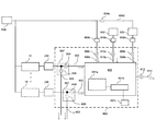
- an exhaust gas treatment system 600 including an exhaust gas treatment chamber 601 is connected to the downstream side of the vacuum pump 246 connected to the exhaust portion of the substrate treatment device 10.
- the vacuum pump 246 and the exhaust gas treatment chamber 601 are connected by an exhaust pipe 603.
- the exhaust pipe 603 is provided with a valve 604 as a first valve from the upstream side (vacuum pump side).
- a bypass exhaust pipe 605 for bypass exhausting the exhaust gas to the equipment exhaust system is connected to the upstream side of the valve 604.
- the bypass exhaust pipe 605 is provided with a valve 606 as a second valve.
- the valve 604 and the valve 606 may be configured by the same valve, that is, a three-way valve 607, instead of being separate valves.
- the exhaust gas of the substrate processing device 10 is configured to be supplied (exhausted) to the exhaust gas processing chamber 601 via the vacuum pump 246, the valve 604, and the exhaust pipe 603.
- the exhaust gas treatment chamber 601 may be configured to be able to supply the exhaust gas of a plurality of substrate treatment devices 10.
- the number of exhaust pipes 603, valves 604, 606, bypass exhaust pipes 605, etc. may be increased by the number of substrate processing devices 10 as shown by the dotted line in FIG.
- the exhaust gas treatment system is provided with at least an exhaust gas treatment chamber 601.
- the exhaust gas treatment chamber 601 is provided with a treatment unit 601a for detoxifying the exhaust gas supplied to the exhaust gas treatment chamber 601 and a detection unit 601b for detecting the operation of the treatment unit 601a. Further, the detection unit 601b is configured so that the detected data (measured value) can be transmitted to the exhaust gas controller 601c or the controller 121 described later.
- the treatment unit 601a is composed of an electrode for generating a flame or plasma or a heating source in the exhaust gas treatment chamber 601.
- the detection unit 601b is composed of a flame sensor, an optical sensor, a matching box, etc., and is configured to be able to detect whether or not processing is being performed in the exhaust gas treatment chamber 601. Specifically, it is configured to be able to measure whether or not a flame or plasma is generated, light, electric power ignited by an electrode, and the like.
- the exhaust gas treatment chamber 601 is supplied with a first inert gas supply source 608 for supplying a nitrogen (N 2 ) gas as a first inert gas and a nitrogen (N 2 ) gas as a second inert gas.
- a second inert gas supply source 609, respectively N 2 gas is constituted to be capable of supplying as an inert gas.
- the first inert gas supply source 608 means the N 2 gas line provided in the equipment of the manufacturing plant of the semiconductor device
- the second inert gas supply source 609 is the substrate treatment device 10 and the exhaust gas treatment system 600. the provided either or both, N 2 gas cylinder or means storable tank N 2 gas.
- the first inert gas supply source 608 and the exhaust gas treatment chamber 601 are connected by a gas supply pipe 608a.
- the gas supply pipe 608a is provided with an MFC 608b and a valve 608c from the upstream side.
- the first inert gas supply unit is composed of a gas supply pipe 608a, an MFC 608b, and a valve 608c.
- the second inert gas supply source 609 and the exhaust gas treatment chamber 601 are connected by a gas supply pipe 609a.
- the gas supply pipe 609a is provided with a flow rate adjusting unit 609b and a valve 609c from the upstream side.
- the flow rate adjusting unit 609b is composed of any of an MFC, a needle valve, and an orifice.
- the inert gas is sent to the exhaust gas treatment chamber. Can be supplied.
- the second inert gas supply unit is composed of a gas supply pipe 609a, a flow rate adjusting unit 609b, and a valve 609c.
- the second inert gas supply source 609 is composed of a tank capable of storing the inert gas
- the first inert gas supply source 608 and the second inert gas supply are supplied as shown by the dotted line in FIG.
- the source 609 is connected by a gas supply pipe 609d, and a valve 609e is provided in the gas supply pipe 609d so that the inert gas can be supplied from the first inert gas supply source 608 to the second inert gas supply source 609. You may.
- the storage of the inert gas in the second inert gas supply source 609 is performed, for example, before the treatment by the substrate processing apparatus 10.
- the exhaust gas treatment chamber 601 is configured to be able to supply an additive gas having an effect of promoting the exhaust gas treatment.
- the added gas is a gas that promotes combustion and generation of plasma.
- the gas that promotes combustion for example, at least one of propane (C 3 H 8 ) gas, hydrogen (H 2 ) gas, oxygen (O 2 ) gas, dry air, and the like is used. Mainly, propane gas is used.
- propane gas is used.
- a gas different from the reducing gas is used.
- the gas that promotes the generation of plasma include rare gases such as argon (Ar) gas, helium (He) gas, and neon (Ne) gas.
- the added gas is supplied from the added gas source 610 to the exhaust gas treatment chamber 601 via the gas supply pipe 610a.
- the gas supply pipe 610a is provided with an MFC 610b and a valve 610c from the upstream side.
- An exhaust pipe 611 for exhausting the exhaust gas treated in the exhaust gas treatment chamber 601 is connected to the exhaust gas treatment chamber 601 so that the exhaust gas can be exhausted to the exhaust equipment of the semiconductor device manufacturing factory.
- the exhaust pipe 611 is provided with a valve 612.
- the exhaust gas treatment system 600 is composed of at least an exhaust gas treatment chamber 601, an exhaust pipe 603,611, a bypass exhaust pipe 605, and valves 604,606,608c, 609c, 612.
- the other configurations described above may be added to the exhaust gas treatment system 600.
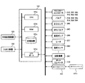
- the controller 121 which is a control unit (control means), is configured as a computer including a CPU (Central Processing Unit) 121a, a RAM (Random Access Memory) 121b, a storage device 121c, and an I / O port 121d.
- the RAM 121b, the storage device 121c, and the I / O port 121d are configured so that data can be exchanged with the CPU 121a via the internal bus.
- An input / output device 122 for inputting / outputting data configured as, for example, a touch panel is connected to the controller 121.
- the storage device 121c is composed of, for example, a flash memory, an HDD (Hard Disk Drive), or the like.
- a control program for controlling the operation of the substrate processing device, a process recipe in which procedures and conditions of a method for manufacturing a semiconductor device to be described later are described, and the like are readablely stored.
- the process recipes are combined so that the controller 121 can execute each step (each step) in the method of manufacturing a semiconductor device described later and obtain a predetermined result, and functions as a program.
- the process recipe, control program, etc. are collectively referred to as a program.
- the RAM 121b is configured as a memory area (work area) in which programs, data, and the like read by the CPU 121a are temporarily held.
- the I / O port 121d has the above-mentioned MFC 312,322,332,512,522,532, valve 314,324,334,514,524,534, pressure sensor 245, APC valve 243, vacuum pump 246, heater 207, temperature. It is configured to be connectable to a sensor 263, a rotation mechanism 267, a boat elevator 115, an exhaust gas treatment system 600, and the like. Further, the exhaust gas treatment system 600 is configured to be connectable to the exhaust gas controller 601c.
- the CPU 121a is configured to read and execute a control program from the storage device 121c and read a recipe or the like from the storage device 121c in response to an input of an operation command from the input / output device 122 or the like.
- the CPU 121a adjusts the flow rate of various gases by the MFC 312, 322, 332, 521, 522, 532, opens and closes the valves 314, 324, 334, 514, 524, 534, and the APC valve so as to follow the contents of the read recipe.
- the CPU 121a or the exhaust gas controller 601c is a processing operation by the processing unit 601a, a detection operation by the detection unit 601b, and a flow rate adjustment operation of various gases by the MFC 608b, 610b and the flow rate adjustment unit 609b based on the detection by the detection unit 601b in the exhaust gas treatment system 600.
- 604,605,608c, 609c, 610c, 612 are configured to control the opening / closing operation and the like.
- the controller 121 is stored in an external storage device (for example, magnetic tape, magnetic disk such as flexible disk or hard disk, optical disk such as CD or DVD, magneto-optical disk such as MO, semiconductor memory such as USB memory or memory card) 123.
- the above-mentioned program can be configured by installing it on a computer.
- the storage device 121c and the external storage device 123 are configured as a computer-readable recording medium. Hereinafter, these are collectively referred to simply as a recording medium.
- the recording medium may include only the storage device 121c alone, may include only the external storage device 123 alone, or may include both of them.
- the program may be provided to the computer by using a communication means such as the Internet or a dedicated line without using the external storage device 123.
- Substrate processing process As one step of the manufacturing process of the semiconductor device (device), an example of a step of forming, for example, a metal film constituting a gate electrode on the wafer 200 will be described with reference to FIG.
- the step of forming the metal film is performed using the processing furnace 202 of the substrate processing apparatus 10 described above. In the following description, the operation of each part constituting the substrate processing device 10 is controlled by the controller 121.
- wafer When the word “wafer” is used in the present specification, it may mean “wafer itself” or “a laminate of a wafer and a predetermined layer, film, etc. formed on the surface thereof". is there.
- wafer surface When the term “wafer surface” is used in the present specification, it may mean “the surface of the wafer itself” or “the surface of a predetermined layer, film, etc. formed on the wafer”. is there.
- board in the present specification is also synonymous with the use of the term "wafer”.
- the inside of the processing chamber 201 is evacuated by the vacuum pump 246 so as to have a desired pressure (degree of vacuum). At this time, the pressure in the processing chamber 201 is measured by the pressure sensor 245, and the APC valve 243 is feedback-controlled based on the measured pressure information (pressure adjustment). The vacuum pump 246 is always kept in operation until at least the processing on the wafer 200 is completed. Further, the inside of the processing chamber 201 is heated by the heater 207 so as to have a desired temperature. At this time, the amount of electricity supplied to the heater 207 is feedback-controlled based on the temperature information detected by the temperature sensor 263 so that the inside of the processing chamber 201 has a desired temperature distribution (temperature adjustment). The heating in the processing chamber 201 by the heater 207 is continuously performed at least until the processing on the wafer 200 is completed.
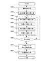
- a step of forming a metal film on the wafer 200 is executed as a film forming step S300.
- the metal film will be described as a W film.
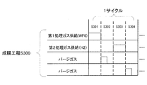
- the film forming step S300 will be described with reference to FIGS. 5 and 6.
- First processing gas supply process S301 First, the first processing gas supply step S301 is performed.
- the valve 314 is opened to supply the raw material gas as the first processing gas into the gas supply pipe 310.
- the raw material gas is WF 6 gas.
- the flow rate of the WF 6 gas is adjusted by the MFC 312, is supplied into the processing chamber 201 from the gas supply hole 410a of the nozzle 410, and is exhausted from the exhaust pipe 231.
- WF 6 gas is supplied to the wafer 200.
- the valve 514 is opened at the same time, and an inert gas such as N 2 gas is allowed to flow in the gas supply pipe 510.
- the flow rate of the N 2 gas flowing through the gas supply pipe 510 is adjusted by the MFC 512 , is supplied into the processing chamber 201 together with the WF 6 gas, and is exhausted from the exhaust pipe 231.
- the valves 524 and 534 are opened to allow the N 2 gas to flow into the gas supply pipes 520 and 530.
- the N 2 gas is supplied into the processing chamber 201 via the gas supply pipes 320 and 330 and the nozzles 420 and 430, and is exhausted from the exhaust pipe 231.
- the APC valve 243 is adjusted so that the pressure in the processing chamber 201 is, for example, 1 to 3990 Pa, preferably 5 to 2660 Pa, and more preferably 10 to 1500 Pa.
- the supply flow rate of the WF 6 gas controlled by the MFC 312 is, for example, a flow rate within the range of 0.01 to 10 slm, preferably 0.3 to 3 slm, and more preferably 0.5 to 2 slm.
- the supply flow rate of the N 2 gas controlled by the MFC 512, 522, 532 is, for example, 0.01 to 20 slm, preferably 0.1 to 10 slm, and more preferably 0.1 to 1 slm.
- the temperature of the heater 207 is set so that the temperature of the wafer 200 is in the range of, for example, 250 to 600 ° C.
- the only gases flowing in the processing chamber 201 are WF 6 gas and N 2 gas.
- a W-containing layer is formed on the wafer 200 (base film on the surface).
- the W-containing layer may be a W layer containing fluorine (F), an adsorption layer of WF 6 , or both of them.
- the valve 314 is closed and the supply of WF 6 gas is stopped.
- the APC valve 243 of the exhaust pipe 231 is left open, the inside of the processing chamber 201 is evacuated by the vacuum pump 246, and the WF 6 after contributing to the formation of the unreacted or W-containing layer remaining in the processing chamber 201.
- Exhaust gas from the processing chamber 201 At this time, the valves 514, 524, 534 are left open to maintain the supply of the N 2 gas into the processing chamber 201.
- the N 2 gas acts as a purge gas, and can enhance the effect of removing the unreacted or WF 6 gas remaining in the treatment chamber 201 after contributing to the formation of the W-containing layer from the treatment chamber 201.
- the reaction gas is H 2 gas.
- the second treatment gas a gas having reducing or flammable properties is usually used.
- the valve 324 is opened and H 2 gas, which is a reducing gas, flows into the gas supply pipe 320.
- the flow rate of the H 2 gas is adjusted by the MFC 322, the gas is supplied into the processing chamber 201 through the gas supply hole 420a of the nozzle 420, and is exhausted from the exhaust pipe 231. At this time, H 2 gas is supplied to the wafer 200.
- the valve 524 is opened at the same time, and an inert gas such as N 2 gas is allowed to flow in the gas supply pipe 520.
- the flow rate of the N 2 gas flowing through the gas supply pipe 520 is adjusted by the MFC 522 , is supplied into the processing chamber 201 together with the H 2 gas, and is exhausted from the exhaust pipe 231.
- the valves 514 and 534 are opened to allow the N 2 gas to flow into the gas supply pipes 510 and 530.
- the N 2 gas is supplied into the processing chamber 201 via the gas supply pipes 310 and 330 and the nozzles 410 and 430, and is exhausted from the exhaust pipe 231.
- the APC valve 243 is adjusted so that the pressure in the processing chamber 201 is set to, for example, a pressure in the range of 1 to 3990 Pa.
- the supply flow rate of the H 2 gas controlled by the MFC 322 is, for example, a flow rate in the range of 0.1 to 50 slm.
- the supply flow rate of the N 2 gas controlled by the MFC 512, 522, 532 is, for example, a flow rate within the range of 0.1 to 20 slm.
- Time for supplying the H 2 gas to the wafer 200 is, for example, time within a range of 0.1 to 20 seconds.
- the temperature of the heater 207 is set so that the temperature of the wafer 200 is in the range of, for example, 200 to 600 ° C.
- the only gases flowing in the processing chamber 201 are H 2 gas and N 2 gas, and by supplying the H 2 gas, for example, from less than one atomic layer to several atomic layers on the wafer 200 (surface base film).
- a W layer is formed as a thick metal layer.
- Determination step S400 By executing the cycle of sequentially performing the first processing gas supply step S301 to the residual gas removal step S304 described above one or more times (predetermined number of times (n times)), a W film having a predetermined thickness is formed on the wafer 200. To do. In this determination step S400, it is determined whether or not the predetermined number of times is n times or more. If it is n times or more, the film forming step S300 is terminated as a Y (Yes) determination. If it is less than n times, an N (No) determination is made and the above cycle is continued. The above cycle is preferably executed a plurality of times.
- the first treated gas and the second treated gas are reacted in the gas phase without executing the residual gas removing steps S302 and S304. You may let the process take place.
- the N 2 gas is supplied into the process chamber 201 from the respective gas supply pipes 510, 520, and 530, is exhausted from the exhaust pipe 231.
- the N 2 gas acts as a purge gas, whereby the inside of the treatment chamber 201 is purged with the inert gas, and the gas and by-products remaining in the treatment chamber 201 are removed from the inside of the treatment chamber 201 (after-purge).
- the atmosphere in the treatment chamber 201 is replaced with the inert gas (replacement of the inert gas), and the pressure in the treatment chamber 201 is restored to the normal pressure (return to atmospheric pressure).
- the substrate processing step is performed.
- the next exhaust gas treatment step S700 is performed while at least H 2 gas, which is a flammable gas, is being supplied.
- Exhaust gas treatment process S700 Exhaust gas containing H 2 gas as a flammable gas exhausted from the substrate processing device 10 is supplied to the exhaust gas processing chamber 601 through the exhaust pipe 603.
- the exhaust gas treatment chamber 601 is detoxified by the treatment unit 601a.
- the detoxification treatment means at least one of combustion, decomposition by plasma, heat treatment (thermal decomposition by heating), stabilization by binding with other elements, dilution, trap (adsorption treatment), and the like. ..
- combustion processing or plasma energy is given to the target gas from the processing unit 601a.
- an active gas is supplied to the exhaust gas treatment chamber 601.
- the first inert gas is supplied from the gas supply pipe 608a.
- the exhaust gas detoxified by these treatments is exhausted from the exhaust gas treatment chamber 601 to the exhaust equipment of the semiconductor device manufacturing factory via the exhaust pipe 611.
- the configuration of the processing unit 601a differs depending on the content of the detoxification treatment.
- it becomes an ignition source.
- plasma decomposition processing it is composed of electrodes that generate plasma.
- thermal decomposition by heating it is composed of a heating element (heater).
- the detoxification treatment a treatment of burning H 2 gas (reacting with oxygen O) to generate water (H 2 O) and detoxifying it is described.
- oxygen is supplied as an additive gas.
- the supply of the additive gas is continued while at least the above-mentioned flammable gas is supplied into the inner tube 204 in the reaction tube.
- propane (C 3 H 8 ) gas is supplied as an additional gas.
- the flow rate of the propane gas is adjusted by the MFC 610b, and the propane gas is supplied to the exhaust gas treatment chamber 601 via the valve 610c.
- the flow rate of propane gas may be adjusted to a preset flow rate, or is required for combustion based on the flow rate of H 2 gas supplied into the inner tube 204 in the above-mentioned substrate processing step.
- the flow rate of propane gas may be automatically set using MFC610b.
- oxygen (O 2 ) gas may be added to promote combustion.
- the flow rate of the O 2 gas is set so that the ratio of hydrogen and oxygen is 2: 1.
- This setting may be calculated by the CPU 121a of the controller 121, and the flow rate setting data may be transmitted from the controller 121 to the MFC 610b. Further, the flow rate setting data may be transmitted from the controller 121 to the MFC 610b via the exhaust gas controller 601c. If the additive gas is not used in the treatment in the exhaust gas treatment chamber 601, the additive gas is not supplied.
- the exhaust gas treatment chamber 601 is filled with the first inert gas that dilutes the exhaust gas. Be supplied.
- the first inert gas is supplied from the first inert gas supply source 608 to the exhaust gas treatment chamber 601 via the gas supply pipe 608a, the MFC 608b, and the valve 608c.
- the first inert gas is adjusted to a predetermined flow rate by the MFC608b.
- the diluting gas is non-combustible such as nitrogen (N 2 ) gas, rare gas element gas such as argon (Ar) gas, helium (He) gas, neon (Ne) gas, and carbon dioxide (CO 2) gas. Sex gas is used.
- N 2 gas or a rare gas such as it can be said that the non-flammable gas.
- the error determination step S701 is configured to be executable.
- the error determination step S701 determines whether or not there is an abnormality in at least the processing in the exhaust gas treatment chamber 601. Specifically, the detection unit 601b provided in the exhaust gas treatment chamber 601 detects whether or not the combustion in the exhaust gas treatment chamber 601 is stopped, and based on the detected data (current value, voltage value, etc.). , Either or both of the exhaust gas controller 601c and the controller 121 determines whether or not the detoxification process is stopped. When the detoxification process is not stopped, the error determination step S701 is repeatedly executed at regular intervals as an N (No) determination. When the detoxification process is stopped, that is, after the Y (Yes) determination is made, the next exhaust route switching step S702 is performed.
- exhaust route switching step S702 In the exhaust route switching step S702, the exhaust route is switched so that the exhaust gas discharged from the substrate treatment device 10 is not supplied to the exhaust gas treatment chamber 601. Specifically, the exhaust gas controller 601c or the controller 121 closes the valve 604 as the first valve, opens the valve 606 as the second valve, and the exhaust gas from the substrate processing device 10 is sent to the bypass exhaust pipe 605. Change the route so that it is exhausted. The area beyond the bypass exhaust pipe 605 is exhausted to the exhaust equipment of the semiconductor device factory. By switching the exhaust route in this way, it is possible to suppress the entry of new exhaust gas into the exhaust gas treatment chamber 601 and suppress the increase in the concentration of the exhaust gas in the exhaust gas treatment chamber 601.
- the inert gas is supplied in order to reduce (dilute) the concentration of the exhaust gas in the exhaust gas treatment chamber 601.
- the pressure of the first inert gas supply source 608 may decrease.
- the first inert gas supply source 608 that supplies the first inert gas supplies the inert gas not only to the exhaust gas treatment chamber 601 but also to the inner tube 204 of the substrate treatment apparatus 10. It is configured to be possible. For example, it may be connected as an inert gas supply source such as the gas supply pipes 510, 520, 530 described above. Further, it may be connected not only to one substrate processing device 10 but also to a plurality of substrate processing devices 10. In such a case, the pressure of the first inert gas supply source 608 may be temporarily lowered, which may affect the processing of the substrate processing apparatus 10. In this case, there arises a problem that the predetermined processing in the substrate processing apparatus 10 is stopped.
- the first inert gas supply source 608 is a pure nitrogen line, it may affect the heat treatment and film formation treatment on the substrate performed by the substrate processing apparatus 10. If the first inert gas supply source 608 is an industrial nitrogen line, purging in the inner tube 204 of the other substrate processing device 10 and the transfer space of the wafer 200 provided in the substrate processing device 10 (not shown). ) May affect the purging, etc. In addition, it may affect the dilution treatment in the exhaust gas treatment system 600 connected to the other substrate treatment device 10. Therefore, in the present disclosure, the controller 121 or the exhaust gas controller 601c supplies the first inert gas to the exhaust gas treatment chamber 601 from the first inert gas supply unit while the exhaust gas is being treated in the exhaust gas treatment chamber 601. Then, when the treatment in the exhaust gas treatment chamber 601 is stopped, the second inert gas supply step S703 can be executed so that the second inert gas is supplied from the second inert gas supply unit to the exhaust gas treatment chamber 601. It is configured in.
- the second inert gas supply step S703 will be described.
- the valve 609c is opened, and the second inert gas is supplied from the second inert gas supply source 609 to the exhaust gas treatment chamber 601 via the gas supply pipe 609a, the flow rate adjusting unit 609b, and the valve 609c. ..
- the second inert gas is supplied at least until the gas concentration in the exhaust gas treatment chamber 601 becomes smaller than a predetermined concentration.
- the supply flow rate from the second inert gas supply source 609 to the exhaust gas treatment chamber 601 continues until the second inert gas supply flow rate stabilizes once and then fluctuates.
- the second inert gas stored in the second inert gas supply source 609 may be used up.
- the supply of the first inert gas may be stopped. Further, the flow rate of the first inert gas is maintained at the same flow rate as that during the normal detoxification treatment, so that the second inert gas is supplied in addition to the supply of the first inert gas. Is also good. Further, the flow rate of the first inert gas may be changed so as to be smaller than the flow rate of the second inert gas.
- the flow rate setting (flow rate data of the second inert gas) of the flow rate adjusting unit 609b may be set to a predetermined flow rate in advance, or is based on the H 2 gas flow rate used in the above-mentioned film forming step.
- the flow rate data of the second inert gas may be calculated and set.
- the flow rate data of the second inert gas may be calculated and set based on the above-mentioned H 2 gas flow rate and the gas characteristic data.
- the characteristic data of the gas includes at least one of the explosion concentration, the molecular weight, the gas type, and the like.
- the flow rate of the inert gas is calculated so that the concentration is smaller than the explosive concentration.
- the inert gas flow rate in the formula is any one of the flow rate of the second inert gas, the flow rate of the first inert gas, and the total flow rate of the second inert gas.
- the lower limit of the flow rate of the inert gas is 1200 slm.
- the lower limit of the inert gas flow rate becomes 1920Slm.
- the explosion concentration of H 2 gas is set to 4%.
- the gas characteristic data such as the explosion concentration and the molecular weight are configured to be readable from the gas safety data sheet (SDS: Safety Data Sheet) data. That is, these data are configured to be recordable in the storage device 121c.
- the flow rate data of the second inert gas calculated by the above formula is the flow rate. It is set as the lower limit value of the adjusting unit 609b. That is, it is impossible to set a flow rate smaller than the calculated inert gas flow rate.
- This setting is executed by the CPU 121a of the controller 121. Further, the calculated flow rate data of the second inert gas is output (notified) to the input / output device 122 without setting the calculated flow rate data of the second inert gas as the lower limit value of the flow rate adjusting unit 609b. ) May be configured.
- the controller 121 tells the input / output device 122 to change the flow rate setting of the needle valve or to an orifice having a flow rate larger than the calculated flow rate.
- the message may be configured to be broadcast so as to encourage the exchange of. With such a configuration, the flow rate setting work of the flow rate adjusting unit 609b becomes easy.
- This flow rate setting is executed at least before the second inert gas supply step S703. If the flow rate adjusting unit 609b is configured such that the flow rate of the needle valve or orifice cannot be easily adjusted, the needle valve is adjusted or the orifice of the corresponding flow rate is used when assembling the substrate processing device 10 or the exhaust gas treatment system 600. Is installed.
- the inert gas may be supplied to the exhaust gas treatment chamber 601 without controlling the flow rate.
- the inert gas By supplying the inert gas without controlling the flow rate, it is possible to shorten the time for reducing the gas concentration in the exhaust gas treatment chamber 601.
- the load of the exhaust equipment (not shown) of the semiconductor manufacturing factory connected to the subsequent stage of the exhaust gas treatment chamber 601 will increase, and that the exhaust gas treatment system 600 needs to have a pressure-resistant structure. Therefore, preferably, the flow rate is adjusted as described above to supply the inert gas to the exhaust gas treatment chamber 601.
- valve 608c which is a part of the first inert gas supply unit
- valve 609c which is a part of the second inert gas supply unit
- a three-way valve connecting the exhaust gas treatment chamber 601, the first inert gas supply unit, and the second inert gas supply unit may be provided.
- the controller 121 or the exhaust gas controller 601c is configured to be able to control the three-way valve when it is determined that the processing of the exhaust gas treatment chamber 601 has stopped.
- (E) By calculating the flow rate of the second inert gas based on the gas flow rate used in the film forming process and the gas characteristic data, the operator of the substrate processing apparatus and the operator of the exhaust gas treatment system It is possible to reduce work mistakes.
- (F) By setting the calculated second inert gas flow rate as the lower limit value, it is possible to reduce work mistakes of the operator of the substrate processing apparatus and the operator of the exhaust gas treatment system.
- (G) By notifying the calculated second inert gas flow rate, it is possible to reduce work mistakes of the operator of the substrate processing apparatus and the operator of the exhaust gas treatment system.
- a reducing gas (combustible gas), although an example of using the H 2 gas, the present disclosure is not limited to this, monosilane ( SiH 4) gas, disilane (Si 2 H 6) gas, may be used silane-based gas and the like. Since these gases are also flammable, the detoxification treatment as described above is required.
- the lower limit of the second inert gas flow rate is 144 slm.
- Si 2 H 6 gas is supplied for 2 slm
- the lower limit of the second inert gas flow rate is 398 slm.
- the lower limit of the explosion concentration is 1.37% for SiH 4 gas and 0.5% for Si 2 H 6 gas, respectively.
- the present disclosure is not limited to this, and a step of forming a titanium nitride (TiN) film may be used.
- TiN titanium nitride
- TiCl 4 gas, SiH 4 gas, and NH 3 gas may be used.
- detoxification process described above may be performed.
- the present disclosure is not limited to the steps of forming these films, and can be applied to, for example, the steps of forming Mo films.
- any Mo-containing gas such as MoO 2 Cl 2 , MoOCl 4 , or the like and any reducing gas such as H 2 , SiH 4 , Si 2 H 6 or the like are used.
- the present disclosure is not limited to the steps of forming a transition metal film such as these, and can be applied to, for example, a step of forming a Si film.
- the formation of the Si film is performed using the above-mentioned silane-based gas.
- the present disclosure has described the case where it is applied to a double reaction tube composed of an outer tube 203 and an inner tube 204, but the present disclosure is not limited to this, and it can be applied to a single reaction tube.
- Substrate processing device 121 ... Controller, 200 ... Wafer (board), 201 ... Processing room
Landscapes
- Chemical & Material Sciences (AREA)
- General Chemical & Material Sciences (AREA)
- Chemical Kinetics & Catalysis (AREA)
- Engineering & Computer Science (AREA)
- Materials Engineering (AREA)
- Mechanical Engineering (AREA)
- Metallurgy (AREA)
- Organic Chemistry (AREA)
- Chemical Vapour Deposition (AREA)
Abstract
Description
以下に本開示の一実施形態について説明する。
基板処理装置10は、加熱手段(加熱機構、加熱系)としてのヒータ207が設けられた処理炉202を備える。ヒータ207は円筒形状であり、保持板としてのヒータベース(図示せず)に支持されることにより垂直に据え付けられている。
排ガス処理システムは、少なくとも排ガス処理室601が設けられている。排ガス処理室601には、排ガス処理室601に供給される排ガスを無害化する処理部601aと処理部601aの動作を検出する検出部601bが設けられている。また、検出部601bは、検出したデータ(測定値)を排ガスコントローラ601c又は、後述のコントローラ121に送信可能に構成されている。ここで、処理部601aは、排ガス処理室601内に、炎又はプラズマを発生させる電極又は、加熱源で構成される。検出部601bは、炎センサ、光センサ、マッチングボックス、等で構成され、排ガス処理室601内での処理が行われているか否かを検出可能に構成されている。具体的には、炎やプラズマが発生しているか否かを光や、電極に引火される電力等を測定可能に構成される。
半導体装置(デバイス)の製造工程の一工程として、ウエハ200上に、例えばゲート電極を構成する金属膜を形成する工程の一例について、図5を用いて説明する。金属膜を形成する工程は、上述した基板処理装置10の処理炉202を用いて実行される。以下の説明において、基板処理装置10を構成する各部の動作はコントローラ121により制御される。
複数枚のウエハ200がボート217に装填(ウエハチャージ)されると、図1に示されているように、複数枚のウエハ200を支持したボート217は、ボートエレベータ115によって持ち上げられて処理室201内に搬入(ボートロード)される。この状態で、シールキャップ219はOリング220を介してアウタチューブ203の下端開口を閉塞した状態となる。
処理室201内が所望の圧力(真空度)となるように真空ポンプ246によって真空排気される。この際、処理室201内の圧力は、圧力センサ245で測定され、この測定された圧力情報に基づき、APCバルブ243がフィードバック制御される(圧力調整)。真空ポンプ246は、少なくともウエハ200に対する処理が完了するまでの間は常時作動させた状態を維持する。また、処理室201内が所望の温度となるようにヒータ207によって加熱される。この際、処理室201内が所望の温度分布となるように、温度センサ263が検出した温度情報に基づきヒータ207への通電量がフィードバック制御される(温度調整)。ヒータ207による処理室201内の加熱は、少なくともウエハ200に対する処理が完了するまでの間は継続して行われる。
続いて、ウエハ200上に、成膜工程S300として、金属膜を形成する工程を実行する。金属膜は、W膜として説明する。成膜工程S300について、図5と図6を用いて説明する。
先ず、第1処理ガス供給工程S301が行われる。バルブ314を開き、ガス供給管310内に第1処理ガスとしての原料ガスを供給する。ここで、原料ガスは、WF6ガスである。WF6ガスは、MFC312により流量調整され、ノズル410のガス供給孔410aから処理室201内に供給され、排気管231から排気される。このとき、ウエハ200に対してWF6ガスが供給される。このとき同時にバルブ514を開き、ガス供給管510内にN2ガス等の不活性ガスを流す。ガス供給管510内を流れたN2ガスは、MFC512により流量調整され、WF6ガスと一緒に処理室201内に供給され、排気管231から排気される。このとき、ノズル420,430内へのWF6ガスの進入を防止するために、バルブ524,534を開き、ガス供給管520,530内にN2ガスを流す。N2ガスは、ガス供給管320,330、ノズル420,430を介して処理室201内に供給され、排気管231から排気される。
W含有層が形成された後、バルブ314を閉じ、WF6ガスの供給を停止する。このとき、排気管231のAPCバルブ243は開いたままとして、真空ポンプ246により処理室201内を真空排気し、処理室201内に残留する未反応もしくはW含有層形成に寄与した後のWF6ガスを処理室201内から排除する。このときバルブ514,524,534は開いたままとして、N2ガスの処理室201内への供給を維持する。N2ガスはパージガスとして作用し、処理室201内に残留する未反応もしくはW含有層形成に寄与した後のWF6ガスを処理室201内から排除する効果を高めることができる。
次に、第2処理ガスとしての反応ガスを供給する工程が行われる。ここで、反応ガスは、H2ガスである。なお、第2処理ガスは、通常、還元性や可燃性の特性を有するガスが用いられる。第2処理ガス供給工程S303では、バルブ324を開き、ガス供給管320内に還元ガスであるH2ガスを流す。H2ガスは、MFC322により流量調整され、ノズル420のガス供給孔420aから処理室201内に供給され、排気管231から排気される。このとき、ウエハ200に対してH2ガスが供給されることとなる。このとき同時にバルブ524を開き、ガス供給管520内にN2ガス等の不活性ガスを流す。ガス供給管520内を流れたN2ガスは、MFC522により流量調整され、H2ガスと一緒に処理室201内に供給され、排気管231から排気される。なお、このとき、ノズル410,430内へのH2ガスの進入を防止するために、バルブ514,534を開き、ガス供給管510,530内にN2ガスを流す。N2ガスは、ガス供給管310,330、ノズル410,430を介して処理室201内に供給され、排気管231から排気される。
W層が形成された後、バルブ324を閉じ、H2ガスの供給を停止する。そして、残留ガス除去工程S302と同様の処理手順により、処理室201内に残留する未反応もしくはW層形成に寄与した後のH2ガスを処理室201内から排除する。
上記した第1処理ガス供給工程S301~残留ガス除去工程S304を順に行うサイクルを1回以上(所定回数(n回))実行することにより、ウエハ200上に、所定の厚さのW膜を形成する。この判定工程S400では、所定回数がn回以上となっているか否かが判定される。n回以上であれば、Y(Yes)判定として、成膜工程S300を終了させる。n回未満であれば、N(No)判定とし、上述のサイクルを継続させる。なお、上述のサイクルは、複数回実行するのが好ましい。
ガス供給管510,520,530のそれぞれからN2ガスを処理室201内へ供給し、排気管231から排気する。N2ガスはパージガスとして作用し、これにより処理室201内が不活性ガスでパージされ、処理室201内に残留するガスや副生成物が処理室201内から除去される(アフターパージ)。その後、処理室201内の雰囲気が不活性ガスに置換され(不活性ガス置換)、処理室201内の圧力が常圧に復帰される(大気圧復帰)。
その後、ボートエレベータ115によりシールキャップ219が下降されて、インナチューブ204の下端が開口される。そして、処理済ウエハ200がボート217に支持された状態でインナチューブ204の下端からインナチューブ204の外部に搬出(ボートアンロード)される。その後、処理済のウエハ200は、ボート217より取り出される(ウエハディスチャージ)。
基板処理装置10から排気された可燃性ガスとしてのH2ガスを含む排気ガスは、排気管603を通り、排ガス処理室601に供給される。排ガス処理室601では、処理部601aにより、無害化される。
排ガス処理室601では、無害化処理が行われる。ここで無害化処理とは、燃焼、プラズマによる分解、加熱処理(加熱による熱分解)、他の元素との結合による安定化、希釈化、トラップ(吸着処理)、等の少なくともいずれかを意味する。燃焼処理や、プラズマが行われる際には、処理部601aから、対象のガスにエネルギーが与えられる。他の元素との結合をさせる際には、活性なガスが排ガス処理室601に供給される。希釈処理の際には、ガス供給管608aから、第1の不活性ガスが供給される。これらの処理によって無害化された排気ガスは、排ガス処理室601から、排気管611を介して、半導体装置の製造工場の排気設備に排気される。
添加ガスの供給は、少なくとも上述の可燃性ガスが、反応管内であるインナチューブ204内に供給されている間継続される。ここでは、添加ガスとして、プロパン(C3H8)ガスが供給される。プロパンガスは、MFC610bで流量調整され、バルブ610cを介して、排ガス処理室601に供給される。なお、プロパンガスの流量は、事前に設定された流量に調整しても良いし、上述の基板処理工程で、インナチューブ204内に供給されるH2ガスの流量に基づいて、燃焼に必要なプロパンガスの流量をMFC610bを用いて自動設定しても良い。また、更に、燃焼を促進させるために、酸素(O2)ガスを添加しても良い。O2ガスの流量は、例えば、水素と酸素の比率が、2:1となる様に、O2ガスの流量を設定する。この設定は、コントローラ121のCPU121aで演算され、コントローラ121から、MFC610bに流量の設定データを送信可能に構成しても良い。また、コントローラ121から、排ガスコントローラ601cを介して、MFC610bに流量の設定データを送信するように構成しても良い。なお、排ガス処理室601での処理において、添加ガスが用いられない場合は、添加ガスは供給されない。
そして、排ガス処理室601内において無害化処理が行われている間であって、排気ガスを処理している間は、排ガス処理室601には、排気ガスを希釈させる第1の不活性ガスが供給される。第1の不活性ガスは、第1不活性ガス供給源608から、ガス供給管608a、MFC608b、バルブ608cを介して排ガス処理室601に供給される。第1の不活性ガスは、MFC608bによって、所定流量に調整されている。ここで、希釈ガスは、窒素(N2)ガスや、アルゴン(Ar)ガス、ヘリウム(He)ガス、ネオン(Ne)ガス、等の希ガス元素ガス、二酸化炭素(CO2)ガス等の不燃性ガスが用いられる。なお、N2ガスや希ガス等も不燃性ガスと言える。本開示では、主にN2ガスを用いている例を記している。
ところで、排ガス処理室601での無害化処理が、何らかの原因(エラー)により、停止する場合がある。これに備えて、エラー判定工程S701を実行可能に構成される。
エラー判定工程S701では、排ガスコントローラ601cと、コントローラ121のいずれか又は両方が、少なくとも排ガス処理室601での処理に異常が有るか否かを判定する。具体的には、排ガス処理室601に設けられた検出部601bが、排ガス処理室601内の燃焼が停止しているか否かを検出し、検出したデータ(電流値、電圧値、等)に基づき、排ガスコントローラ601cとコントローラ121のいずれか又は両方が、無害化処理が停止しているか否かを判定する。無害化処理が停止していない場合は、N(No)判定として、一定周期で、エラー判定工程S701を繰り返し実行させる。無害化処理が停止している場合、即ち、Y(Yes)判定された後は、次の、排気ルート切替工程S702が行われる。
排気ルート切替工程S702では、基板処理装置10から排出される排気ガスが排ガス処理室601に供給されない様に排気ルートの切替が行われる。具体的には、排ガスコントローラ601cまたはコントローラ121が、第1のバルブとしてのバルブ604を閉じ、第2のバルブとしてのバルブ606を開き、基板処理装置10からの排気ガスは、バイパス排気管605に排気される様にルート変更する。バイパス排気管605から先は、半導体装置の工場の排気設備に排気される。この様に排気ルートを切り替えることで、排ガス処理室601に新たな排気ガスが入り込むことを抑制し、排ガス処理室601内での排ガスの濃度上昇を抑制することが可能となる。
第2不活性ガス供給工程S703について説明する。この工程では、バルブ609cが開き、第2不活性ガス供給源609から、ガス供給管609a、流量調整部609b、バルブ609cを介して、排ガス処理室601に第2の不活性ガスが供給される。
ここで、流量調整部609bの流量設定(第2の不活性ガスの流量データ)は、事前に所定流量に設定されていても良いし、上述の成膜工程で用いられるH2ガス流量を基に、第2の不活性ガスの流量データを算出して設定しても良い。また、上述のH2ガス流量とガスの特性データに基づいて第2の不活性ガスの流量データを算出して設定しても良い。ここでガスの特性データとは、爆発濃度、分子量、ガス種類、等、の少なくともいずれかを含む。希釈対象のガスが、可燃性ガスや爆発性のガスである場合、爆発濃度よりも小さい濃度となる様に、不活性ガスの流量が算出される。例えば、「濃度X=可燃性ガス流量/(可燃性ガス流量+不活性ガス流量)」の式から、必要な不活性ガス流量を算出することができる。ここで、式中の不活性ガス流量とは、第2の不活性ガスの流量、第1の不活性ガスの流量と第2の不活性ガスの流量の合計値のいずれかとなる。例えば、H2ガスを50slm供給している場合には、不活性ガス流量の下限は、1200slmとなる。H2ガスを80slm供給している場合には、不活性ガス流量の下限は、1920slmとなる。ここでH2ガスの爆発濃度は、4%としている。なお、爆発濃度、分子量、等のガスの特性データは、ガスの安全データシート(SDS:Safety Data Sheet)データから読み取り可能に構成されている。即ち、これらのデータは記憶装置121cに記録可能に構成されている。
本実施形態によれば、以下に示す1つまたは複数の効果を得ることができる。
(a)排ガス処理室内の可燃性ガスの濃度を減少させることができる。
(b)排ガス処理室での無害化処理が停止した場合も、可燃性ガスの濃度を減少させることができる。
(c)第2不活性ガス供給源を用いることにより、第1不活性ガス供給源の圧力低下を抑制することが可能となる。
(d)成膜処理で用いるガス流量に基づいて、第2の不活性ガスの流量を算出することで、基板処理装置の作業者(オペレーター)や排ガス処理システムの作業者の作業ミスを低減することがでできる。
(e)成膜処理で用いるガス流量とガスの特性データに基づいて、第2の不活性ガスの流量を算出することで、基板処理装置の作業者(オペレーター)や排ガス処理システムの作業者の作業ミスを低減することがでできる。
(f)算出した第2の不活性ガス流量を下限値として設定することで、基板処理装置の作業者(オペレーター)や排ガス処理システムの作業者の作業ミスを低減することがでできる。
(g)算出した第2の不活性ガス流量を報知することで、基板処理装置の作業者(オペレーター)や排ガス処理システムの作業者の作業ミスを低減することがでできる。
Claims (15)
- 基板を収容する反応管と、
前記反応管内に処理ガスを供給する処理ガス供給部と、
前記反応管内の前記処理ガスを排気する排気部と、
前記排気部に接続され、前記排気された処理ガスを処理する排ガス処理室と、
前記反応管内に第1の不活性ガスを供給する不活性ガス供給源に接続され、前記排ガス処理室に前記第1の不活性ガスを供給する第1不活性ガス供給部と、
前記排ガス処理室に第2の不活性ガスを供給する第2不活性ガス供給部と、
前記排ガス処理室内のガスを排気する排気管と、
前記排ガス処理室で前記処理ガスを処理している間は、前記第1不活性ガス供給部から前記排ガス処理室に前記第1の不活性ガスを供給し、
前記排ガス処理室の処理が停止した時は前記第2不活性ガス供給部から前記排ガス処理室に前記第2の不活性ガスを供給する様に前記第1不活性ガス供給部と前記第2不活性ガス供給部とを制御可能に構成された制御部と、
を有する基板処理装置。 - 前記排ガス処理室には、前記排ガス処理室での処理状態を検出する検出部が設けられ、
前記制御部は、前記検出部が出力したデータに基づいて、前記処理が停止しているか否かを判定可能に構成される
請求項1に記載の基板処理装置。 - 前記制御部は、
前記排ガス処理室の処理が停止していると判定した後、前記第1の不活性ガスの供給に加えて前記第2の不活性ガスを供給するように前記第1不活性ガス供給部と前記第2不活性ガス供給部とを制御可能に構成される
請求項2に記載の基板処理装置。 - 前記制御部は、前記排ガス処理室の処理が停止していると判定した後、
前記第2不活性ガス供給部から前記排ガス処理室に前記第2の不活性ガスを供給する際に、前記第2の不活性ガスの流量を前記第1の不活性ガスの流量よりも多くなるように前記第1不活性ガス供給部と前記第2不活性ガス供給部とを制御可能に構成される
請求項2又は3に記載の基板処理装置。 - 前記排ガス処理室と前記第1不活性ガス供給部と前記第2不活性ガス供給部とは、三方弁で接続され、
前記制御部は、前記排ガス処理室の処理が停止したと判定したときに前記三方弁を制御可能に構成される
請求項2乃至4のいずれか一項に記載の基板処理装置。 - 前記制御部は、
前記処理ガス供給部が供給する前記処理ガスの流量に基づいて、前記第2の不活性ガスの流量データを算出可能に構成される
請求項1乃至5のいずれか一項に記載の基板処理装置。 - 前記制御部は、
前記処理ガス供給部が供給する前記処理ガスの流量と前記処理ガスの特性データに基づいて、前記第2の不活性ガスの流量データを算出可能に構成される
請求項1乃至5のいずれか一項に記載の基板処理装置。 - 前記制御部は、
前記第2の不活性ガスの流量データを基に、前記第2の不活性ガスの流量を調整する流量調整部の流量を設定可能に構成される
請求項6又は7に記載の基板処理装置。 - データを入出力する入出力装置を有し、
前記制御部は、
前記第2の不活性ガスの流量データに対応するメッセージを前記入出力装置に送信可能に構成される
請求項6又は7に記載の基板処理装置。 - 前記第2不活性ガス供給部には、前記第2の不活性ガスを事前に設定された流量に調整する流量調整部が、設けられる
請求項1乃至3のいずれか一項に記載の基板処理装置。 - 前記排気部の前記排ガス処理室の上流側には、排気設備に接続されるバイパス排気管が接続され、
前記排気部の前記バイパス排気管との接続位置より下流側であって前記排ガス処理室の上流側に設けられた第1のバルブと、
前記バイパス排気管に設けられた第2のバルブと、を有し、
前記制御部は、前記排ガス処理室の処理が停止したことを判定した後、前記第1のバルブを閉じ、前記第2のバルブを開ける様に前記第1のバルブと前記第2のバルブを制御可能に構成される
請求項2乃至5のいずれか一項に記載の基板処理装置。 - (a)基板を反応管内に収容する工程と、
(b)前記反応管内に処理ガスを供給する工程と、
(c)前記反応管内の前記処理ガスを排気する工程と、
(d)前記排気された前記処理ガスを排ガス処理室に供給する工程と、
(e)前記排ガス処理室で前記処理ガスを処理する工程と、
(f)少なくとも前記(e)工程の間、前記反応管内と前記排ガス処理室に第1の不活性ガスを供給する工程と、
(g)前記(e)工程が停止した後に前記排ガス処理室に第2の不活性ガスを供給する工程と、
を有する半導体装置の製造方法。 - (a)基板を反応管内に収容させる手順と、
(b)前記反応管内に処理ガスを供給させる手順と、
(c)前記反応管内の前記処理ガスを排気させる手順と、
(d)前記排気された前記処理ガスを排ガス処理室に供給させる手順と、
(e)前記排ガス処理室で前記処理ガスを処理させる手順と、
(f)少なくとも前記(e)手順の間、前記反応管内と前記排ガス処理室に第1の不活性ガスを供給させる手順と、
(g)前記(e)手順が停止した後に前記排ガス処理室に第2の不活性ガスを供給させる手順と、
をコンピュータが基板処理装置に実行させるプログラム。 - (a)基板を反応管内に収容させる手順と、
(b)前記反応管内に処理ガスを供給させる手順と、
(c)前記反応管内の前記処理ガスを排気させる手順と、
(d)前記排気された前記処理ガスを排ガス処理室に供給させる手順と、
(e)前記排ガス処理室で前記処理ガスを処理させる手順と、
(f)少なくとも前記(e)手順の間、前記反応管内と前記排ガス処理室に第1の不活性ガスを供給させる手順と、
(g)前記(e)手順が停止した後に前記排ガス処理室に第2の不活性ガスを供給させる手順と、
をコンピュータが基板処理装置に実行させるプログラムが記録されたコンピュータ読み取り可能な記録媒体。 - 基板を処理する基板処理装置から排気された処理ガスを処理する排ガス処理室と、
前記基板処理装置に第1の不活性ガスを供給する不活性ガス供給源に接続され、前記排ガス処理室に前記第1の不活性ガスを供給する第1不活性ガス供給部と、
前記排ガス処理室に第2の不活性ガスを供給する第2不活性ガス供給部と、
前記排ガス処理室内のガスを排気する排気管と、
前記排ガス処理室で前記処理ガスを処理している間は、前記第1不活性ガス供給部から前記排ガス処理室に前記第1の不活性ガスを供給し、
前記排ガス処理室の処理が停止した時は前記第2不活性ガス供給部から前記排ガス処理室に前記第2の不活性ガスを供給する様に前記第1不活性ガス供給部と前記第2不活性ガス供給部とを制御可能に構成された制御部と、を有する排ガス処理システム。
Priority Applications (4)
| Application Number | Priority Date | Filing Date | Title |
|---|---|---|---|
| CN202080060372.7A CN114341399B (zh) | 2019-09-19 | 2020-07-28 | 基板处理装置、基板处理方法、半导体装置的制造方法以及计算机可读记录介质 |
| KR1020227008610A KR102843100B1 (ko) | 2019-09-19 | 2020-07-28 | 기판 처리 장치, 기판 처리 방법, 반도체 장치의 제조 방법 및 프로그램 |
| JP2021546535A JP7250152B2 (ja) | 2019-09-19 | 2020-07-28 | 基板処理装置、半導体装置の製造方法、基板処理方法、プログラム及び排ガス処理システム |
| US17/696,615 US12601052B2 (en) | 2019-09-19 | 2022-03-16 | Substrate processing apparatus, substrate processing method, method of manufacturing semiconductor device and non-transitory computer-readable recording medium |
Applications Claiming Priority (2)
| Application Number | Priority Date | Filing Date | Title |
|---|---|---|---|
| JP2019170304 | 2019-09-19 | ||
| JP2019-170304 | 2019-09-19 |
Related Child Applications (1)
| Application Number | Title | Priority Date | Filing Date |
|---|---|---|---|
| US17/696,615 Continuation US12601052B2 (en) | 2019-09-19 | 2022-03-16 | Substrate processing apparatus, substrate processing method, method of manufacturing semiconductor device and non-transitory computer-readable recording medium |
Publications (1)
| Publication Number | Publication Date |
|---|---|
| WO2021053972A1 true WO2021053972A1 (ja) | 2021-03-25 |
Family
ID=74884197
Family Applications (1)
| Application Number | Title | Priority Date | Filing Date |
|---|---|---|---|
| PCT/JP2020/028905 Ceased WO2021053972A1 (ja) | 2019-09-19 | 2020-07-28 | 基板処理装置、半導体装置の製造方法、プログラム、記録媒体および排ガス処理システム |
Country Status (5)
| Country | Link |
|---|---|
| US (1) | US12601052B2 (ja) |
| JP (1) | JP7250152B2 (ja) |
| KR (1) | KR102843100B1 (ja) |
| CN (1) | CN114341399B (ja) |
| WO (1) | WO2021053972A1 (ja) |
Families Citing this family (1)
| Publication number | Priority date | Publication date | Assignee | Title |
|---|---|---|---|---|
| KR20240146650A (ko) * | 2023-03-29 | 2024-10-08 | 주식회사 히타치하이테크 | 웨이퍼 처리 장치 |
Citations (4)
| Publication number | Priority date | Publication date | Assignee | Title |
|---|---|---|---|---|
| JP2005223144A (ja) * | 2004-02-05 | 2005-08-18 | Hitachi Kokusai Electric Inc | 基板処理装置 |
| JP3145006U (ja) * | 2008-04-03 | 2008-09-25 | 株式会社テック・エンジニアリング | 安全施策ユニット |
| JP2013153159A (ja) * | 2011-12-27 | 2013-08-08 | Hitachi Kokusai Electric Inc | 基板処理装置、半導体装置の製造方法およびプログラム |
| JP2014168046A (ja) * | 2013-01-30 | 2014-09-11 | Hitachi Kokusai Electric Inc | 基板処理装置、半導体装置の製造方法およびプログラム |
Family Cites Families (24)
| Publication number | Priority date | Publication date | Assignee | Title |
|---|---|---|---|---|
| JPH0570954A (ja) | 1991-09-19 | 1993-03-23 | Nec Kyushu Ltd | 排気ガス希釈装置 |
| JP3262623B2 (ja) * | 1993-02-17 | 2002-03-04 | 東京エレクトロン株式会社 | 減圧処理方法及び装置 |
| KR100252213B1 (ko) * | 1997-04-22 | 2000-05-01 | 윤종용 | 반도체소자제조장치및그제조방법 |
| JP4387573B2 (ja) * | 1999-10-26 | 2009-12-16 | 東京エレクトロン株式会社 | プロセス排気ガスモニタ装置及び方法、半導体製造装置、及び半導体製造装置管理システム及び方法 |
| JP2001203211A (ja) | 2000-01-20 | 2001-07-27 | Hitachi Kokusai Electric Inc | 水素アニール処理方法及びその装置 |
| JP4172938B2 (ja) * | 2002-02-14 | 2008-10-29 | 昭和電工株式会社 | 排ガスの処理方法および処理装置 |
| TW200527491A (en) * | 2003-12-23 | 2005-08-16 | John C Schumacher | Exhaust conditioning system for semiconductor reactor |
| KR20060063188A (ko) * | 2004-12-07 | 2006-06-12 | 삼성전자주식회사 | 화학기상증착장치 및 그를 이용한 화학기상증착방법 |
| US20060162742A1 (en) * | 2005-01-26 | 2006-07-27 | Tokyo Electron Limited | Cleaning method of processing apparatus, program for performing the method, and storage medium for storing the program |
| JP2006303414A (ja) | 2005-03-23 | 2006-11-02 | Hitachi Kokusai Electric Inc | 基板処理システム |
| KR20070036249A (ko) * | 2005-09-29 | 2007-04-03 | 삼성전자주식회사 | 공정 가스의 배기 방법 및 이를 수행하기 위한 기판 가공장치 |
| GB0521944D0 (en) * | 2005-10-27 | 2005-12-07 | Boc Group Plc | Method of treating gas |
| JP2009088308A (ja) | 2007-10-01 | 2009-04-23 | Hitachi Kokusai Electric Inc | 基板処理装置 |
| JP5457654B2 (ja) | 2008-09-17 | 2014-04-02 | 株式会社日立国際電気 | 半導体装置の製造方法及び熱処理炉のクリーニング方法 |
| JP2010207771A (ja) | 2009-03-12 | 2010-09-24 | Jx Nippon Oil & Energy Corp | 排ガス処理装置および排ガス処理方法 |
| JP5538128B2 (ja) | 2010-08-09 | 2014-07-02 | 東京エレクトロン株式会社 | 排気方法およびガス処理装置 |
| JP2012142482A (ja) * | 2011-01-05 | 2012-07-26 | Hitachi Kokusai Electric Inc | 基板処理装置 |
| US20120304930A1 (en) * | 2011-06-03 | 2012-12-06 | Gregory Scott Verdict | Chamber exhaust in-situ cleaning for processing apparatuses |
| KR101740616B1 (ko) * | 2012-11-26 | 2017-05-26 | 가부시키가이샤 히다치 고쿠사이 덴키 | 반도체 장치의 제조 방법, 기판 처리 장치 및 기록 매체 |
| JP6308584B2 (ja) * | 2013-02-28 | 2018-04-11 | 株式会社日立国際電気 | 半導体装置の製造方法、基板処理装置、基板処理システム及びプログラム |
| JP6209786B2 (ja) | 2013-09-06 | 2017-10-11 | 大陽日酸株式会社 | 排気ガス処理システム |
| JP6257442B2 (ja) | 2014-05-15 | 2018-01-10 | 東京エレクトロン株式会社 | 減圧処理装置における排ガス防爆方法 |
| JP6449696B2 (ja) | 2015-03-19 | 2019-01-09 | 大陽日酸株式会社 | 排ガス処理方法 |
| JP6548622B2 (ja) * | 2016-09-21 | 2019-07-24 | 株式会社Kokusai Electric | 半導体装置の製造方法、基板処理装置及びプログラム |
-
2020
- 2020-07-28 CN CN202080060372.7A patent/CN114341399B/zh active Active
- 2020-07-28 JP JP2021546535A patent/JP7250152B2/ja active Active
- 2020-07-28 WO PCT/JP2020/028905 patent/WO2021053972A1/ja not_active Ceased
- 2020-07-28 KR KR1020227008610A patent/KR102843100B1/ko active Active
-
2022
- 2022-03-16 US US17/696,615 patent/US12601052B2/en active Active
Patent Citations (4)
| Publication number | Priority date | Publication date | Assignee | Title |
|---|---|---|---|---|
| JP2005223144A (ja) * | 2004-02-05 | 2005-08-18 | Hitachi Kokusai Electric Inc | 基板処理装置 |
| JP3145006U (ja) * | 2008-04-03 | 2008-09-25 | 株式会社テック・エンジニアリング | 安全施策ユニット |
| JP2013153159A (ja) * | 2011-12-27 | 2013-08-08 | Hitachi Kokusai Electric Inc | 基板処理装置、半導体装置の製造方法およびプログラム |
| JP2014168046A (ja) * | 2013-01-30 | 2014-09-11 | Hitachi Kokusai Electric Inc | 基板処理装置、半導体装置の製造方法およびプログラム |
Also Published As
| Publication number | Publication date |
|---|---|
| KR20220046661A (ko) | 2022-04-14 |
| US12601052B2 (en) | 2026-04-14 |
| KR102843100B1 (ko) | 2025-08-05 |
| CN114341399B (zh) | 2024-12-17 |
| US20220205089A1 (en) | 2022-06-30 |
| JP7250152B2 (ja) | 2023-03-31 |
| JPWO2021053972A1 (ja) | 2021-03-25 |
| CN114341399A (zh) | 2022-04-12 |
Similar Documents
| Publication | Publication Date | Title |
|---|---|---|
| US12148621B2 (en) | Method of processing substrate, method of manufacturing semiconductor device, recording medium, and substrate processing apparatus | |
| JP6647260B2 (ja) | 半導体装置の製造方法、基板処理装置及びプログラム | |
| US20240344194A1 (en) | Method of manufacturing semiconductor device, substrate processing apparatus, and recording medium | |
| US11594412B2 (en) | Method of manufacturing semiconductor device, substrate processing apparatus, and recording medium | |
| US10176988B2 (en) | Method of manufacturing semiconductor device, substrate processing apparatus, and recording medium | |
| US12272579B2 (en) | Substrate processing apparatus, substrate suppport and method of manufacturing semiconductor device | |
| US20230392257A1 (en) | Substrate processing apparatus, method of processing substrate, method of manufacturing semiconductor device, recording medium, and exhaust system | |
| JPWO2020054299A1 (ja) | 半導体装置の製造方法、基板処理装置及び記録媒体 | |
| JP6742265B2 (ja) | 洗浄副生成物の付着抑制方法及びこれを用いた反応室内のクリーニング方法、並びに室温成膜装置 | |
| WO2022064550A1 (ja) | 半導体装置の製造方法、記録媒体及び基板処理装置 | |
| JP7250152B2 (ja) | 基板処理装置、半導体装置の製造方法、基板処理方法、プログラム及び排ガス処理システム | |
| JP2006303414A (ja) | 基板処理システム | |
| JP2013197421A (ja) | 基板処理装置 | |
| JP6910387B2 (ja) | 半導体装置の製造方法、基板処理方法、基板処理装置およびプログラム | |
| EP4245884A1 (en) | Gas cleaning method, method of processing substrate, method of manufacturing semiconductor device, and substrate processing apparatus | |
| WO2020066800A1 (ja) | 半導体装置の製造方法、基板処理装置、及びプログラム | |
| JP6937332B2 (ja) | 基板処理装置、半導体装置の製造方法およびプログラム | |
| WO2022059170A1 (ja) | 半導体装置の製造方法、記録媒体及び基板処理装置 | |
| JPWO2020188632A1 (ja) | 半導体装置の製造方法、基板処理方法、プログラムおよび基板処理装置 | |
| JP2020143333A (ja) | 基板処理装置、半導体装置の製造方法及びプログラム | |
| WO2022064549A1 (ja) | 半導体装置の製造方法、記録媒体及び基板処理装置 | |
| TWI874921B (zh) | 原料供給系統、基板處理裝置及半導體裝置之製造方法 | |
| WO2023188465A1 (ja) | 基板処理装置、ガス供給システム、基板処理方法、半導体装置の製造方法及びプログラム | |
| WO2019058554A1 (ja) | 半導体装置の製造方法、基板処理装置およびプログラム |
Legal Events
| Date | Code | Title | Description |
|---|---|---|---|
| 121 | Ep: the epo has been informed by wipo that ep was designated in this application |
Ref document number: 20865248 Country of ref document: EP Kind code of ref document: A1 |
|
| ENP | Entry into the national phase |
Ref document number: 2021546535 Country of ref document: JP Kind code of ref document: A |
|
| ENP | Entry into the national phase |
Ref document number: 20227008610 Country of ref document: KR Kind code of ref document: A |
|
| NENP | Non-entry into the national phase |
Ref country code: DE |
|
| 122 | Ep: pct application non-entry in european phase |
Ref document number: 20865248 Country of ref document: EP Kind code of ref document: A1 |
|
| WWG | Wipo information: grant in national office |
Ref document number: 11202202637S Country of ref document: SG |
|
| WWP | Wipo information: published in national office |
Ref document number: 11202202637S Country of ref document: SG |