WO2021049340A1 - 車両の熱交換システム - Google Patents
車両の熱交換システム Download PDFInfo
- Publication number
- WO2021049340A1 WO2021049340A1 PCT/JP2020/032808 JP2020032808W WO2021049340A1 WO 2021049340 A1 WO2021049340 A1 WO 2021049340A1 JP 2020032808 W JP2020032808 W JP 2020032808W WO 2021049340 A1 WO2021049340 A1 WO 2021049340A1
- Authority
- WO
- WIPO (PCT)
- Prior art keywords
- heat exchange
- air
- cooling
- exchange unit
- heat
- Prior art date
- Legal status (The legal status is an assumption and is not a legal conclusion. Google has not performed a legal analysis and makes no representation as to the accuracy of the status listed.)
- Ceased
Links
Images


Classifications
-
- B—PERFORMING OPERATIONS; TRANSPORTING
- B60—VEHICLES IN GENERAL
- B60H—ARRANGEMENTS OF HEATING, COOLING, VENTILATING OR OTHER AIR-TREATING DEVICES SPECIALLY ADAPTED FOR PASSENGER OR GOODS SPACES OF VEHICLES
- B60H1/00—Heating, cooling or ventilating [HVAC] devices
- B60H1/00321—Heat exchangers for air-conditioning devices
-
- B—PERFORMING OPERATIONS; TRANSPORTING
- B60—VEHICLES IN GENERAL
- B60H—ARRANGEMENTS OF HEATING, COOLING, VENTILATING OR OTHER AIR-TREATING DEVICES SPECIALLY ADAPTED FOR PASSENGER OR GOODS SPACES OF VEHICLES
- B60H1/00—Heating, cooling or ventilating [HVAC] devices
- B60H1/32—Cooling devices
- B60H1/3204—Cooling devices using compression
- B60H1/3228—Cooling devices using compression characterised by refrigerant circuit configurations
- B60H1/32284—Cooling devices using compression characterised by refrigerant circuit configurations comprising two or more secondary circuits, e.g. at evaporator and condenser side
-
- B—PERFORMING OPERATIONS; TRANSPORTING
- B60—VEHICLES IN GENERAL
- B60H—ARRANGEMENTS OF HEATING, COOLING, VENTILATING OR OTHER AIR-TREATING DEVICES SPECIALLY ADAPTED FOR PASSENGER OR GOODS SPACES OF VEHICLES
- B60H1/00—Heating, cooling or ventilating [HVAC] devices
- B60H1/00642—Control systems or circuits; Control members or indication devices for heating, cooling or ventilating devices
- B60H1/00814—Control systems or circuits characterised by their output, for controlling particular components of the heating, cooling or ventilating installation
- B60H1/00878—Control systems or circuits characterised by their output, for controlling particular components of the heating, cooling or ventilating installation the components being temperature regulating devices
- B60H1/00899—Controlling the flow of liquid in a heat pump system
- B60H1/00914—Controlling the flow of liquid in a heat pump system where the flow direction of the refrigerant does not change and there is a bypass of the condenser
-
- B—PERFORMING OPERATIONS; TRANSPORTING
- B60—VEHICLES IN GENERAL
- B60H—ARRANGEMENTS OF HEATING, COOLING, VENTILATING OR OTHER AIR-TREATING DEVICES SPECIALLY ADAPTED FOR PASSENGER OR GOODS SPACES OF VEHICLES
- B60H1/00—Heating, cooling or ventilating [HVAC] devices
- B60H1/00007—Combined heating, ventilating, or cooling devices
- B60H1/00021—Air flow details of HVAC devices
-
- B—PERFORMING OPERATIONS; TRANSPORTING
- B60—VEHICLES IN GENERAL
- B60H—ARRANGEMENTS OF HEATING, COOLING, VENTILATING OR OTHER AIR-TREATING DEVICES SPECIALLY ADAPTED FOR PASSENGER OR GOODS SPACES OF VEHICLES
- B60H1/00—Heating, cooling or ventilating [HVAC] devices
- B60H1/00007—Combined heating, ventilating, or cooling devices
- B60H1/00207—Combined heating, ventilating, or cooling devices characterised by the position of the HVAC devices with respect to the passenger compartment
-
- B—PERFORMING OPERATIONS; TRANSPORTING
- B60—VEHICLES IN GENERAL
- B60H—ARRANGEMENTS OF HEATING, COOLING, VENTILATING OR OTHER AIR-TREATING DEVICES SPECIALLY ADAPTED FOR PASSENGER OR GOODS SPACES OF VEHICLES
- B60H1/00—Heating, cooling or ventilating [HVAC] devices
- B60H1/00271—HVAC devices specially adapted for particular vehicle parts or components and being connected to the vehicle HVAC unit
- B60H1/00278—HVAC devices specially adapted for particular vehicle parts or components and being connected to the vehicle HVAC unit for the battery
-
- B—PERFORMING OPERATIONS; TRANSPORTING
- B60—VEHICLES IN GENERAL
- B60H—ARRANGEMENTS OF HEATING, COOLING, VENTILATING OR OTHER AIR-TREATING DEVICES SPECIALLY ADAPTED FOR PASSENGER OR GOODS SPACES OF VEHICLES
- B60H1/00—Heating, cooling or ventilating [HVAC] devices
- B60H1/00642—Control systems or circuits; Control members or indication devices for heating, cooling or ventilating devices
- B60H1/00814—Control systems or circuits characterised by their output, for controlling particular components of the heating, cooling or ventilating installation
- B60H1/00878—Control systems or circuits characterised by their output, for controlling particular components of the heating, cooling or ventilating installation the components being temperature regulating devices
- B60H1/00885—Controlling the flow of heating or cooling liquid, e.g. valves or pumps
-
- B—PERFORMING OPERATIONS; TRANSPORTING
- B60—VEHICLES IN GENERAL
- B60H—ARRANGEMENTS OF HEATING, COOLING, VENTILATING OR OTHER AIR-TREATING DEVICES SPECIALLY ADAPTED FOR PASSENGER OR GOODS SPACES OF VEHICLES
- B60H1/00—Heating, cooling or ventilating [HVAC] devices
- B60H1/02—Heating, cooling or ventilating [HVAC] devices the heat being derived from the propulsion plant
- B60H1/04—Heating, cooling or ventilating [HVAC] devices the heat being derived from the propulsion plant from cooling liquid of the plant
-
- B—PERFORMING OPERATIONS; TRANSPORTING
- B60—VEHICLES IN GENERAL
- B60H—ARRANGEMENTS OF HEATING, COOLING, VENTILATING OR OTHER AIR-TREATING DEVICES SPECIALLY ADAPTED FOR PASSENGER OR GOODS SPACES OF VEHICLES
- B60H1/00—Heating, cooling or ventilating [HVAC] devices
- B60H1/02—Heating, cooling or ventilating [HVAC] devices the heat being derived from the propulsion plant
- B60H1/14—Heating, cooling or ventilating [HVAC] devices the heat being derived from the propulsion plant otherwise than from cooling liquid of the plant, e.g. heat from the grease oil, the brakes, the transmission unit
- B60H1/143—Heating, cooling or ventilating [HVAC] devices the heat being derived from the propulsion plant otherwise than from cooling liquid of the plant, e.g. heat from the grease oil, the brakes, the transmission unit the heat being derived from cooling an electric component, e.g. electric motors, electric circuits, fuel cells or batteries
-
- F—MECHANICAL ENGINEERING; LIGHTING; HEATING; WEAPONS; BLASTING
- F25—REFRIGERATION OR COOLING; COMBINED HEATING AND REFRIGERATION SYSTEMS; HEAT PUMP SYSTEMS; MANUFACTURE OR STORAGE OF ICE; LIQUEFACTION SOLIDIFICATION OF GASES
- F25B—REFRIGERATION MACHINES, PLANTS OR SYSTEMS; COMBINED HEATING AND REFRIGERATION SYSTEMS; HEAT PUMP SYSTEMS
- F25B1/00—Compression machines, plants or systems with non-reversible cycle
-
- F—MECHANICAL ENGINEERING; LIGHTING; HEATING; WEAPONS; BLASTING
- F25—REFRIGERATION OR COOLING; COMBINED HEATING AND REFRIGERATION SYSTEMS; HEAT PUMP SYSTEMS; MANUFACTURE OR STORAGE OF ICE; LIQUEFACTION SOLIDIFICATION OF GASES
- F25B—REFRIGERATION MACHINES, PLANTS OR SYSTEMS; COMBINED HEATING AND REFRIGERATION SYSTEMS; HEAT PUMP SYSTEMS
- F25B47/00—Arrangements for preventing or removing deposits or corrosion, not provided for in another subclass
- F25B47/02—Defrosting cycles
-
- B—PERFORMING OPERATIONS; TRANSPORTING
- B60—VEHICLES IN GENERAL
- B60H—ARRANGEMENTS OF HEATING, COOLING, VENTILATING OR OTHER AIR-TREATING DEVICES SPECIALLY ADAPTED FOR PASSENGER OR GOODS SPACES OF VEHICLES
- B60H1/00—Heating, cooling or ventilating [HVAC] devices
- B60H1/00007—Combined heating, ventilating, or cooling devices
- B60H1/00207—Combined heating, ventilating, or cooling devices characterised by the position of the HVAC devices with respect to the passenger compartment
- B60H2001/00214—Devices in front of the passenger compartment
-
- B—PERFORMING OPERATIONS; TRANSPORTING
- B60—VEHICLES IN GENERAL
- B60H—ARRANGEMENTS OF HEATING, COOLING, VENTILATING OR OTHER AIR-TREATING DEVICES SPECIALLY ADAPTED FOR PASSENGER OR GOODS SPACES OF VEHICLES
- B60H1/00—Heating, cooling or ventilating [HVAC] devices
- B60H1/00271—HVAC devices specially adapted for particular vehicle parts or components and being connected to the vehicle HVAC unit
- B60H2001/00307—Component temperature regulation using a liquid flow
Definitions
- This disclosure relates to a vehicle heat exchange system.
- the heat exchange system described in Patent Document 1 includes a radiator and an outdoor heat exchanger that exchange heat with the outside air, which is the air outside the vehicle interior.
- the radiator cools the cooling water by exchanging heat between the cooling water of the internal combustion engine flowing inside the radiator and the outside air.
- the outdoor heat exchanger functions as a so-called capacitor that condenses the heat medium by exchanging heat between the heat medium flowing inside the outdoor heat exchanger and the outside air.
- the outdoor heat exchanger is a component of the refrigeration cycle of the vehicle air conditioner.
- the refrigeration cycle consists of an outdoor heat exchanger, a compressor, an expansion valve, and an evaporator.
- the air conditioner air is cooled by exchanging heat between the air conditioner air that air-conditions the vehicle interior and the evaporator. Further, the air conditioner is provided with a heater core that heats the conditioned air by using the cooling water of the internal combustion engine as a heat source. In the air conditioner, the air-conditioned air cooled by the evaporator is blown into the passenger compartment to cool and dehumidify the passenger compartment, and the air-conditioned air heated by the heater core is blown into the passenger compartment to heat the passenger compartment. Is done.
- a heat pump cycle capable of cooling and heating the conditioned air is used in the air conditioner instead of the refrigerating cycle that only cools the conditioned air.
- the indoor heat exchanger is driven as an evaporator.
- the heat pump cycle includes a hydrothermal medium heat exchanger that exchanges heat between the high-temperature and high-pressure heat medium compressed by the compressor and the cooling water. In the hydrothermal medium heat exchange, the cooling water that has absorbed the heat of the heat medium flows to the heater core, so that the conditioned air can be heated in the heater core.
- a heater core is not used when cooling an internal combustion engine and cooling a vehicle interior. If the cooling water of the internal combustion engine can be dissipated in this heater core, for example, the radiator can be simplified.
- An object of the present disclosure is to provide a vehicle heat exchange system capable of simplifying the configuration while being capable of cooling the heating element and air-conditioning the vehicle interior.
- the vehicle heat exchange system includes a cooling side heat exchange unit, a first air conditioning side heat exchange unit, a hydrothermal medium heat exchange unit, a second air conditioning side heat exchange unit, an air conditioning passage, and the like.
- a cooling side heat exchange unit cooling water for cooling the heating element of the vehicle flows inside, and heat exchange is performed between the air flowing through the cooling passage and the cooling water.
- the first air-conditioning side heat exchange unit operates as an evaporator in the heat pump system and cools the air-conditioned air by exchanging heat between the air-conditioned air for air-conditioning the passenger compartment and the heat medium circulating in the heat pump system. It is possible to do.
- the hydrothermal medium heat exchange unit operates as a condenser in the heat pump system, and cools the heat medium by exchanging heat between the heat medium circulating in the heat pump system and the cooling water.
- cooling water that has absorbed heat from the heat medium flows in the water heat medium heat exchange unit, and the air-conditioned air can be heated by exchanging heat between the cooling water and the air-conditioned air. It is possible.
- the air conditioning passage the first air conditioning side heat exchange section and the second air conditioning side heat exchange section are arranged, and the air conditioning air that has passed through the first air conditioning side heat exchange section and the second air conditioning side heat exchange section is guided into the vehicle interior. ..
- an outside-vehicle compartment communication port for guiding the air passing through the second air-conditioning side heat exchange section to the outside of the vehicle interior is provided. Cooling water for cooling the heating element flows through the heat exchange section on the second air-conditioning side, and the air that has passed through the heat exchange section on the second air-conditioning side is discharged to the outside of the passenger compartment through the communication port outside the passenger compartment.
- the cooling water for cooling the heating element is applied not only to the cooling side heat exchange unit but also to the second air conditioning side heat exchange unit. Since it flows, the cooling water can be dissipated by both the cooling side heat exchange section and the second air conditioning side heat exchange section. That is, both the cooling side heat exchange unit and the second air conditioning side heat exchange unit function as radiators. As a result, the amount of heat radiated required for the cooling side heat exchange section can be reduced as compared with the case where the cooling water is radiated only by the cooling side heat exchange section, so that the cooling side heat exchange section can be downsized or cooled.
- the cooling side heat exchange unit such as reducing the number of heat exchange parts in the side heat exchange unit.
- the conditioned air can be heated and cooled in the first air-conditioned side heat exchange section and the second air-conditioned side heat exchange section, the interior of the vehicle can be air-conditioned.
- the heating element can be cooled by the cooling water flowing through the cooling side heat exchange section.
- the air that has exchanged heat with the cooling water in the second air-conditioning side heat exchange unit is discharged to the outside of the vehicle interior through the external communication port, it is possible to suppress the influence of the air on the air conditioning in the vehicle interior.
- FIG. 1 is a diagram schematically showing the structure of the vehicle of the embodiment.
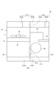
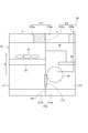
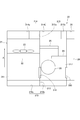
- FIG. 2 is a diagram schematically showing the structure of the heat exchange module of the embodiment.
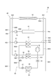
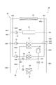
- FIG. 3 is a block diagram showing a schematic configuration of the heat exchange system of the embodiment.
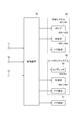
- FIG. 4 is a block diagram showing an electrical configuration of the heat exchange system of the embodiment.
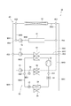
- FIG. 5 is a block diagram showing an operation example of the heat exchange system in the heating element cooling mode of the embodiment.
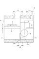
- FIG. 6 is a block diagram showing an operation example of the heat exchange module in the heating element cooling mode of the embodiment.
- FIG. 7 is a block diagram showing an operation example of the heat exchange system in the heating element cooling / cooling mode of the embodiment.
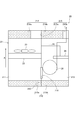
- FIG. 8 is a block diagram showing an operation example of the heat exchange module in the heating element cooling / cooling mode of the embodiment.
- FIG. 9 is a block diagram showing an operation example of the heat exchange system in the heating mode of the embodiment.
- FIG. 10 is a block diagram showing an operation example of the heat exchange module in the heating mode of the embodiment.
- FIG. 11 is a block diagram showing an operation example of the heat exchange system in the frost formation suppression mode of the embodiment.
- FIG. 12 is a block diagram showing an operation example of the heat exchange module in the frost formation suppression mode of the embodiment.
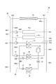
- FIG. 13 is a block diagram showing a schematic configuration of a heat exchange system of a modified example.
- FIG. 14 is a block diagram showing an operation example of the heat exchange system in the first heating element cooling mode of the modified example.
- FIG. 15 is a block diagram showing an operation example of the heat exchange system in the second heating element cooling mode of the modified example.
- FIG. 16 is a block diagram showing an operation example of the heat exchange system in the first and second heating element cooling modes of the modified example.
- FIG. 17 is a block diagram showing an operation example of the heat exchange system in the first and second heating element cooling / cooling modes of the modified example.
- FIG. 18 is a block diagram showing an operation example of the heat exchange system in the first heating mode of the modified example.
- FIG. 19 is a block diagram showing an operation example of the heat exchange system in the second heating mode of the modified example.
- FIG. 20 is a block diagram showing an operation example of the heat exchange system in the first heating / dehumidifying mode of the modified example.
- FIG. 21 is a block diagram showing an operation example of the heat exchange system in the second heating / dehumidifying mode of the modified example.
- FIG. 22 is a diagram schematically showing the structure of the heat exchange module of another embodiment.
- FIG. 23 is a diagram schematically showing an operation example of the heat exchange module of another embodiment.
- the heat exchange module 20 of this embodiment is arranged on the upper part of the bonnet 11 of the vehicle 10.
- the vehicle 10 of the present embodiment is a so-called electric vehicle that travels by the power of a motor generator. Therefore, the vehicle is provided with a battery for supplying electric power to the motor generator, an inverter device for converting the DC electric power charged in the battery into AC electric power, and the like.
- the traveling wind of the vehicle 10 is introduced into the heat exchange module 20 as outside air.
- the heat exchange module 20 has a function as a radiator that dissipates cooling water for cooling a battery, an inverter device, and the like, and a function as a heat exchanger that generates conditioned air that air-conditions the vehicle interior. ..
- the heat exchange module 20 includes a case 21, a cooling side heat exchange unit 22, a first blower 23, a first air conditioning side heat exchange unit 24, and a second air conditioning side heat exchange unit. 25 and a second blower 26 are provided.
- the direction indicated by the arrow A in the figure indicates the flow direction of the outside air.
- An outside air introduction port 210 for introducing outside air from the bonnet 11 of the vehicle 10 is formed at one end of the case 21 on the upstream side of the outside air flow direction A.
- the case 21 is formed with a partition wall 213 that divides the space inside the case 21 into a cooling passage 211 and an air conditioning passage 212.
- the outside air introduced from the outside air introduction port 210 is introduced into each of the cooling passage 211 and the air conditioning passage 212.
- the cooling passage 211 and the air conditioning passage 212 are communicated with each other outside the vehicle interior, and the cooling passage 211 and the air conditioning passage 212 are communicated with each other inside the vehicle interior.
- a vehicle interior communication port 215 is formed.
- the case 21 houses a cooling side heat exchange unit 22, an air conditioning side heat exchange unit 24, 25, and a blower device 23, 26.
- the portion of the outside air introduction port 210 communicating with the cooling passage 211 is referred to as the "cooling side outside air introduction port 210a", and the portion communicating with the air conditioning passage 212 is referred to as the “air conditioning side outside air introduction port 210a”. It is called “210b”.
- the portion communicating with the cooling passage 211 is referred to as “cooling side passenger compartment outside communication port 214a”
- the portion communicating with the air conditioning passage 212 is referred to as "air conditioning side passenger compartment outside communication port 214b”. It is called.
- cooling side vehicle interior communication port 215a the portion communicating with the cooling passage 211
- air conditioning side vehicle interior communication port 215b the portion communicating with the air conditioning passage 212
- the partition wall 213 is formed with a communication passage 216 that communicates the upstream portion of the cooling passage 211 and the upstream portion of the air conditioning passage 212.
- the communication passage 216 makes it possible to circulate air between the cooling passage 211 and the air conditioning passage 212.
- the cooling side heat exchange unit 22 and the first blower device 23 are arranged in the cooling passage 211.
- the first blower device 23 is arranged on the downstream side of the cooling side heat exchange unit 22 in the outside air flow direction A.
- the first blower device 23 is an axial flow type blower that blows conditioned air flowing through the cooling passage 211 to the cooling side heat exchange unit 22.
- the first blower 23 is not limited to the axial flow type blower, and any blower can be used.
- Cooling water is flowing inside the cooling side heat exchange unit 22.
- This cooling water cools the heating element by circulating the heating element such as the motor generator, the battery, and the inverter device of the vehicle 10.
- the cooling side heat exchange unit 22 mainly functions as a so-called radiator that radiates and cools the cooling water by exchanging heat between the cooling water flowing inside the cooling water and the conditioned air flowing outside the cooling water.
- the first air-conditioning side heat exchange unit 24, the second air-conditioning side heat exchange unit 25, and the second air-conditioning device 26 are arranged in the air-conditioning passage 212.
- the second air-conditioning device 26 is, for example, a sirocco fan, and blows air-conditioned air flowing through the air-conditioned passage 212 to the first air-conditioned side heat exchange unit 24 and the second air-conditioned side heat exchange unit 25.
- the first air-conditioning side heat exchange unit 24 and the second air-conditioning side heat exchange unit 25 are arranged on the downstream side of the second air blower 26 in the outside air flow direction A.
- the heat medium of the heat pump cycle used in the air conditioner of the vehicle 10 flows through the first air conditioner side heat exchange unit 24 and the second air conditioner side heat exchange unit 25.
- the first air-conditioning side heat exchange unit 24 mainly functions as a so-called evaporator that cools the conditioned air by exchanging heat between the heat medium flowing inside the heat exchange unit and the conditioned air flowing outside the heat medium.
- the second air-conditioning side heat exchange unit 25 is arranged on the downstream side of the first air-conditioning side heat exchange unit 24 in the outside air flow direction A.
- the second air-conditioning side heat exchange unit 25 mainly functions as a so-called heater core that heats the conditioned air by exchanging heat between the heat medium flowing inside the heat medium and the conditioned air flowing outside the heat medium.
- the air-conditioning passage 212 guides the air that has passed through the first air-conditioning side heat exchange unit 24 and the second air-conditioning side heat exchange unit 25 into the vehicle interior through the air-conditioning side vehicle interior communication port 215b.
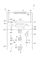
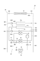
- the heat exchange system 30 in which the heat exchange module 20 is used will be described in detail with reference to FIG.
- the heat exchange system 30 includes a cooling system 40 for cooling the heating element 41 and air conditioning of the vehicle 10 when the motor generator, battery, inverter device, etc. of the vehicle 10 are used as the heating element 41. It includes a heat pump system 50 used in the device.
- the cooling system 40 has a heating element 41, a first hydrothermal medium heat exchange unit 61, and a heat exchange module 20 shown in FIG. 2 with respect to the cooling side heat exchange unit 22 of the heat exchange module 20 shown in FIG. Has a structure in which the second air-conditioning side heat exchange unit 25 is connected in parallel.
- cooling water circulates in the cooling side heat exchange unit 22, the heating element 41, the first hydrothermal medium heat exchange unit 61, and the second air conditioning side heat exchange unit 25.
- cooling side heat exchange unit 22 and the heating element 41 are connected by an annular flow path W40.
- a pump 42 is provided on the upstream side of the heating element 41 in the annular flow path W40.
- the pump 42 circulates the cooling water in the annular flow path W40 by sucking and pumping the cooling water flowing through the annular flow path W40.
- the cooling system 40 is provided with a first bypass flow path W41 so as to connect the upstream side portion and the downstream side portion of the cooling side heat exchange portion 22 in the annular flow path W40.
- a second air-conditioning side heat exchange unit 25 is arranged in the first bypass flow path W41.
- the second air-conditioning side heat exchange unit 25 is connected in parallel to the heating element 41 by the first bypass flow path W41.
- Switching valves 450 and 451 such as a three-way valve for switching the connection state of the flow paths W40 and W41 are provided at two connecting portions between the annular flow path W40 and the first bypass flow path W41, respectively.
- the cooling system 40 is provided with a second bypass flow path W42 so as to connect the upstream side portion and the downstream side portion of the second air conditioning side heat exchange unit 25 in the first bypass flow path W41.
- the second bypass flow path W42 is provided with a first hydrothermal medium heat exchange section 61.
- the first hydrothermal medium heat exchange unit 61 is connected in parallel to the heating element 41 and the second air conditioning side heat exchange unit 25 by the second bypass flow path W42.
- the first hydrothermal medium heat exchange unit 61 is a portion that exchanges heat between the cooling water that circulates in the cooling system 40 and the heat medium that circulates in the heat pump system 50.
- a pump 43 is provided in the second bypass flow path W42.
- the pump 43 sucks and pumps the cooling water flowing through the second bypass flow path W42 to circulate the cooling water through the second bypass flow path W42.
- Switching valves 452 and 453 such as a three-way valve for switching the connection state of the flow paths W41 and W42 are provided at two connection portions between the first bypass flow path W41 and the second bypass flow path W42, respectively. ..
- the cooling system 40 is provided with a third bypass flow path W43 so as to connect a portion of the annular flow path W40 on the upstream side of the pump 42 and a portion on the downstream side of the heating element 41.
- a pump 44 and a second hydrothermal medium heat exchange unit 62 are arranged in the third bypass flow path W43.
- the second hydrothermal medium heat exchange unit 62 is a portion that exchanges heat between the cooling water that circulates in the cooling system 40 and the heat medium that circulates in the heat pump system 50.
- the pump 44 circulates the cooling water in the third bypass flow path W43 by sucking and pumping the cooling water flowing through the third bypass flow path W43.
- Switching valves 454 and 455 such as a three-way valve for switching the connection state of the flow paths W40 and W43 are provided at two connecting portions between the annular flow path W40 and the third bypass flow path W43, respectively.
- the heating element 41 is cooled by circulating the cooling water cooled by the cooling side heat exchange unit 22 through the heating element 41. Further, in the cooling system 40, the cooling water is circulated between the cooling side heat exchange unit 22 and the hydrothermal medium heat exchange units 61 and 62 by switching the connection state of the flow path by the switching valves 450 to 455. It is also possible to circulate the cooling water between the heating element 41 and the hydrothermal medium heat exchange units 61 and 62.
- the heat pump system 50 includes a first air conditioning side heat exchange unit 24, a pressure regulating valve 51, a compressor 52, a first expansion valve 53, a second expansion valve 54, a first hydrothermal medium heat exchange unit 61, and the like. It is provided with a second hydrothermal medium heat exchange unit 62.
- the first air conditioning side heat exchange section 24, the pressure regulating valve 51, the compressor 52, the first hydrothermal medium heat exchange section 61, and the first expansion valve 53 are annularly connected by an annular flow path W50. A heat medium circulates in the annular flow path W50.
- the compressor 52 sucks and compresses the heat medium flowing through the annular flow path W50 to discharge the high-temperature and high-pressure vapor-phase heat medium, and circulates the heat medium in the annular flow path W50.
- the high-temperature and high-pressure vapor phase heat medium discharged from the compressor 52 flows into the first hydrothermal medium heat exchange section 61 through the annular flow path W50.
- first hydrothermal medium heat exchange unit 61 heat exchange is performed between the high-temperature and high-pressure vapor-phase heat medium discharged from the compressor 52 and the cooling water circulating in the cooling system 40, so that the heat medium is heated. Heat is released into the cooling water and the heat medium condenses.
- the high-pressure liquid-phase heat medium condensed in the first hydrothermal medium heat exchange section 61 flows into the first expansion valve 53 through the annular flow path W50.
- the first expansion valve 53 expands and depressurizes the high-pressure liquid-phase heat medium discharged from the first hydrothermal medium heat exchange unit 61.
- the low-pressure liquid-phase heat medium decompressed by the first expansion valve 53 flows into the first air-conditioning side heat exchange section 24 through the annular flow path W50.
- heat is exchanged between the low-pressure liquid-phase heat medium discharged from the first expansion valve 53 and the conditioned air, so that the heat medium absorbs the heat of the conditioned air.
- the conditioned air is cooled.
- the low-temperature vapor-phase heat medium evaporated by absorbing the heat of the conditioned air flows from the first air-conditioned side heat exchange unit 24 to the pressure regulating valve 51 to adjust the pressure, and then is sucked into the compressor 52.
- the heat pump system 50 when the heat medium circulates in the annular flow path W50, the heat pump system 50 operates as a so-called refrigeration cycle for cooling the conditioned air.
- the heat pump system 50 is provided with a bypass flow path W51 so as to connect a portion of the annular flow path W50 on the downstream side of the first hydrothermal medium heat exchange portion 61 and a portion on the upstream side of the compressor 52. ..
- the bypass flow path W51 is provided with a second expansion valve 54 and a second hydrothermal medium heat exchange section 62.
- Switching valves 550 and 551 such as a three-way valve for switching the connection state of the flow paths W50 and W51 are provided at two connecting portions between the annular flow path W50 and the bypass flow path W51.
- the switching valves 550 and 551 form, for example, a flow path in which the heat medium does not flow in the bypass flow path W51 and the heat medium flows only in the annular flow path W50.
- the heat pump system 50 can be driven as a refrigeration cycle as described above.
- the heat medium does not flow through the first expansion valve 53 and the first air conditioning side heat exchange section 24, and the compressor 52, the first hydrothermal medium heat exchange section 61, and the bypass flow path W51 A flow path through which the heat medium flows is constructed.
- the second expansion valve 54 expands and depressurizes the high-pressure liquid-phase heat medium discharged from the first hydrothermal medium heat exchange unit 61.
- the low-pressure liquid-phase heat medium decompressed by the second expansion valve 54 flows into the second hydrothermal medium heat exchange section 62 through the bypass flow path W51.
- the second hydrothermal medium heat exchange unit 62 heat is exchanged between the low-pressure liquid-phase heat medium discharged from the second expansion valve 54 and the cooling water flowing through the third bypass flow path W43 of the cooling system 40. By doing so, the heat of the cooling water is absorbed by the heat medium. The low-pressure vapor-phase heat medium evaporated by absorbing the heat of the cooling water is sucked into the compressor 52.
- the compressor 52 sucks and compresses the low-pressure gas phase heat medium discharged from the second hydrothermal medium heat exchange unit 62, thereby discharging the high-temperature and high-pressure gas phase heat medium.
- the high-temperature and high-pressure vapor phase heat medium discharged from the compressor 52 flows into the first hydrothermal medium heat exchange section 61.
- heat exchange is performed between the high-temperature and high-pressure vapor-phase heat medium discharged from the compressor 52 and the cooling water flowing through the second bypass flow path W42 of the cooling system 40.
- the heat of the heat medium is absorbed by the cooling water.
- the heat pump system 50 can both cool and heat the conditioned air.
- the heat exchange system 30 includes a control device 70 that controls each of the systems 40 and 50.
- the control device 70 is mainly composed of a microcomputer having a CPU, a memory, and the like.
- the control device 70 executes various processes for controlling the systems 40 and 50 by executing a program stored in the memory in advance.
- the control device 70 incorporates the output signals of the temperature sensors 71 and 72 and the operation unit 73.
- the temperature sensor 71 detects the temperature of the heating element 41 and outputs a signal corresponding to the detected temperature of the heating element 41 to the control device 70.
- the temperature sensor 72 detects the temperature of the cooling side heat exchange unit 22, and outputs a signal corresponding to the detected temperature of the cooling side heat exchange unit 22 to the control device 70.
- the operation unit 73 is a part operated by the occupant of the vehicle 10.
- the operation unit 73 can perform, for example, an operation of selecting whether to heat or cool the vehicle interior, an operation of selecting a set temperature of the vehicle interior, and the like.
- the operation unit 73 outputs a signal corresponding to the operation of the occupant to the control device 70.
- the cooling system 40 is provided with door members 460 to 462.
- the door members 460 to 462 open and close the cooling side outside air introduction port 210a, the cooling side vehicle interior communication port 214a, and the cooling side vehicle interior communication port 215a of the cooling passage 211 shown in FIG. 2, respectively.
- the heat pump system 50 is provided with door members 560 to 562.
- the door members 560 to 562 open and close the air-conditioning side outside air introduction port 210b, the air-conditioning side vehicle interior communication port 214b, and the air-conditioning side vehicle interior communication port 215b, respectively, of the air conditioning passage 212 shown in FIG.
- the heat exchange system 30 is provided with a door member 31 for opening and closing the communication passage 216 shown in FIG.
- the door members 460 to 462, 560 to 562, 31 are components of the heat exchange module 20.
- the control device 70 is cooled by the output signals of the temperature sensors 71 and 72 and the operation unit 73 according to the temperature of the heating element 41, the temperature of the cooling side heat exchange unit 22, the operation of the occupant on the operation unit 73, and the like. It controls each component of the system 40, each component of the heat pump system 50, and the door member 31. As a result, the control device 70 drives each of the systems 40 and 50 in any of the heating element cooling mode, the heating element cooling / cooling mode, the heating mode, and the frost formation suppression mode.
- FIGS. 5, 7, 9, and 11 the flow path through which the cooling water or the heat medium is flowing is shown by a solid line, and the flow path through which the cooling water or the heat medium is not flowing is shown by a broken line.
- FIGS. 6, 8, 10, and 12 the closed portion of the outside air introduction port 210, the vehicle interior outside communication port 214, the vehicle interior communication port 215, and the communication passage 216 is point hatched. Is illustrated in. Further, in FIGS. 6, 8, 10, and 12, the air flow direction is indicated by an arrow.
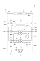
- the heating element cooling mode is a mode for cooling the heating element 41.
- the control device 70 operates the systems 40 and 50 in the heating element cooling mode based on the temperature of the heating element 41 becoming equal to or higher than a predetermined temperature.
- a cooling water flow path and a heat medium flow path are formed in each of the systems 40 and 50 as shown in FIG.
- cooling water flows through the heating element 41, the cooling side heat exchange unit 22, and the second air conditioning side heat exchange unit 25, and the first hydrothermal medium heat exchange unit 61 and
- the open / closed state of the switching valves 450 to 455 is switched so that the cooling water does not flow to the second hydrothermal medium heat exchange unit 62.
- the control device 70 drives the pump 42 and stops the pumps 43 and 44. Further, the control device 70 does not circulate the heat medium in the heat pump system 50 by stopping the compressor 52 of the heat pump system 50.
- the cooling side outside air introduction port 210a, the air conditioning side outside air introduction port 210b, the cooling side vehicle room outside communication port 214a, and the air conditioning side vehicle room outside communication port 214b are opened. Further, each door member 460 to 462, 560 to 562, 31 is controlled so that the cooling side vehicle interior communication port 215a, the air conditioning side vehicle interior communication port 215b, and the communication passage 216 are closed. Further, the control device 70 drives the blowers 23 and 26. As a result, in the cooling passage 211, the outside air introduced from the cooling side outside air introduction port 210a passes through the cooling side heat exchange unit 22, and then is discharged to the outside of the vehicle interior from the cooling side vehicle interior outside communication port 214a.
- the outside air introduced from the air-conditioning side outside air introduction port 210b passes through the second air-conditioning side heat exchange unit 25, and then is discharged to the outside of the vehicle interior from the air-conditioning side vehicle interior outdoor communication port 214b.
- the cooling side heat exchange unit 22 exchanges heat between the cooling water flowing inside the cooling water and the outside air flowing through the cooling passage 211. , The cooling water is cooled. Further, in the second air-conditioning side heat exchange unit 25, the cooling water is cooled by heat exchange between the cooling water flowing inside the second air-conditioning side heat exchange unit 25 and the outside air flowing through the air-conditioning passage 212. Utilizing this, in the heating element cooling mode, as shown in FIG. 5, the cooling water that has absorbed the heat of the heating element 41 is flowed not only to the cooling side heat exchange unit 22 but also to the second air conditioning side heat exchange unit 25.
- the cooling water is dissipated by both the cooling side heat exchange unit 22 and the second air conditioning side heat exchange unit 25. That is, in the heating element cooling mode, if the cooling side heat exchange unit 22 is the first radiator, the second air conditioning side heat exchange unit 25 functions as the second radiator.
- the heating element 41 is cooled by the cooling water cooled by the cooling side heat exchange unit 22 and the second air conditioning side heat exchange unit 25 circulating in the heating element 41.
- the heating element cooling mode is a mode in which only the heating element 41 is cooled.
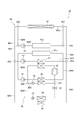
- the heating element cooling / cooling mode is a mode for cooling the heating element 41 and the interior of the vehicle.
- the control device 70 sets the systems 40 and 50 in the heating element cooling / cooling mode when the temperature of the heating element 41 is equal to or higher than a predetermined temperature and the cooling of the vehicle interior is selected by the operation unit 73. Make it work.
- each system 40, 50 may be operated in the heating element cooling / cooling mode.
- the flow paths of the cooling water and the heat medium as shown in FIG. 7 are formed in each of the systems 40 and 50.
- cooling water flows through the heating element 41, the cooling side heat exchange unit 22, the first hydrothermal medium heat exchange unit 61, and the second air conditioning side heat exchange unit 25, and the cooling water flows to the second. 2
- the open / closed state of the switching valves 450 to 455 is switched so that the cooling water does not flow to the hydrothermal medium heat exchange unit 62.
- the control device 70 drives the pumps 42 and 43 of the cooling system 40.
- the heat medium flows through the compressor 52, the first hydrothermal medium heat exchange unit 61, the first expansion valve 53, the first air conditioning side heat exchange unit 24, and the pressure regulating valve 51, and the second water.
- the open / closed states of the switching valves 550 and 551 are switched so that the heat medium does not flow through the heat medium heat exchange unit 62, and the compressor 52 is driven.
- the control device 70 includes a cooling side outside air introduction port 210a, an air conditioning side outside air introduction port 210b, a cooling side vehicle compartment outside communication port 214a, an air conditioning side vehicle interior communication port 214b, and an air conditioning side vehicle interior.
- Each door member 460 to 462, 560 to 562, 31 is controlled so that the communication port 215b is in the open state and the cooling side vehicle interior communication port 215a and the communication passage 216 are in the closed state. Further, the control device 70 drives the blowers 23 and 26.
- the outside air introduced from the cooling side outside air introduction port 210a passes through the cooling side heat exchange unit 22, and then is discharged to the outside of the vehicle interior from the cooling side vehicle interior outside communication port 214a.
- the air-conditioning passage 212 after the outside air introduced from the air-conditioning side outside air introduction port 210b passes through the first air-conditioning side heat exchange unit 24 and the second air-conditioning side heat exchange unit 25, the air-conditioning side vehicle interior communication port 214b and air conditioning It is discharged to the inside of the vehicle and the outside of the vehicle from the side vehicle interior communication port 215b, respectively.
- the cooling side heat exchange unit 22 exchanges heat between the cooling water flowing inside the cooling water and the outside air flowing through the cooling passage 211.
- the cooling water is cooled.
- the cooling water is cooled by heat exchange between the cooling water flowing inside the second air-conditioning side heat exchange unit 25 and the outside air flowing through the air-conditioning passage 212.
- the cooling water that has absorbed the heat of the heating element 41 flows to the cooling side heat exchange section 22 and the second air conditioning side heat exchange section 25, so that the cooling side heat is generated. Cooling water is dissipated by both the exchange unit 22 and the second air conditioning side heat exchange unit 25.
- the cooling side heat exchange unit 22 if used as the first radiator, the second air conditioning side heat exchange unit 25 functions as the second radiator.
- the cooling water cooled by the cooling side heat exchange unit 22 and the second air conditioning side heat exchange unit 25 circulates in the heating element 41, so that the heating element 41 can be cooled.
- the cooling water cooled in the cooling side heat exchange unit 22 and the second air conditioning side heat exchange unit 25 flows to the first hydrothermal medium heat exchange unit 61.
- the first hydrothermal medium heat exchange unit 61 heat exchange is performed between the high-temperature and high-pressure vapor-phase heat medium compressed by the compressor 52 and the cooling water, so that the heat of the heat medium is absorbed by the cooling water. And the heat medium condenses.
- the first hydrothermal medium heat exchange unit 61 substantially functions as a capacitor.
- the high-pressure liquid-phase heat medium condensed in the first hydrothermal medium heat exchange unit 61 becomes a low-pressure liquid-phase heat medium by being depressurized through the first expansion valve 53, and then becomes the low-pressure liquid-phase heat exchange unit 24.
- the first air-conditioning side heat exchange unit 24 heat is exchanged between the low-pressure liquid-phase heat medium flowing inside the heat exchange unit 24 and the outside air flowing through the air-conditioning passage 212, so that the outside air is exchanged. It is cooled.
- the first air conditioning side heat exchange unit 24 functions as an evaporator.
- the outside air cooled by the first air-conditioning side heat exchange unit 24 is introduced into the vehicle interior as air-conditioning air through the air-conditioning side vehicle interior communication port 215b to cool the vehicle interior. Therefore, the heat pump system 50 operates as a refrigeration cycle.
- the heating element cooling / cooling mode is a mode in which both the heating element 41 is cooled and the passenger compartment is cooled.
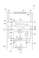
- the heating mode is a mode for heating the interior of the vehicle.
- the control device 70 operates the systems 40 and 50 in the heating mode when the operation unit 73 selects heating in the vehicle interior.
- each system 40, 50 may be operated in the heating element cooling / cooling mode.
- the heating mode the flow paths of the cooling water and the heat medium as shown in FIG. 9 are formed in each of the systems 40 and 50.
- the cooling water circulates between the cooling side heat exchange unit 22 and the second hydrothermal medium heat exchange unit 62, and the control device 70 and the first hydrothermal medium heat exchange unit 61
- the open / closed state of the switching valves 450 to 455 is switched so that the cooling water circulates with the second air conditioning side heat exchange unit 25.
- the control device 70 drives the pumps 42 and 43 of the cooling system 40.
- the heat medium flows through the compressor 52, the first hydrothermal medium heat exchange unit 61, the second expansion valve 54, and the second hydrothermal medium heat exchange unit 62, and the first air conditioning side heat exchange unit
- the open / closed states of the switching valves 550 and 551 are switched so that the heat medium does not flow through the 24, and the compressor 52 is driven.
- the cooling side vehicle interior communication port 215a, the air conditioning side vehicle interior communication port 215b, and the communication passage 216 are in an open state, and the cooling side outside air introduction port 210a and the air conditioning side.
- Each door member 460 to 462, 560 to 562, 31 is controlled so that the outside air introduction port 210b, the cooling side vehicle interior outside communication port 214a, and the air conditioning side vehicle interior outside communication port 214b are closed.
- the control device 70 stops the first blower device 23 and drives the second blower device 26.
- the air in the vehicle interior introduced from the cooling side vehicle interior communication port 215a passes through the cooling passage 211, the communication passage 216, and the air conditioning passage 212 in this order, and then flows from the air conditioning side vehicle interior communication port 215b into the vehicle interior. become.
- the control device 70 may drive the first blower 23.
- the air inside the vehicle is referred to as "inside air”.
- the cooling side heat exchange unit 22 By forming the air flow as shown in FIG. 10, in the cooling side heat exchange unit 22, heat exchange is performed between the cooling water flowing inside the cooling water and the inside air flowing through the cooling passage 211. , The heat of the inside air is absorbed by the cooling water.
- the cooling water that has absorbed the heat of the inside air flows to the second hydrothermal medium heat exchange unit 62 as shown in FIG. A low-pressure liquid-phase heat medium decompressed by the second expansion valve 54 flows through the second hydrothermal medium heat exchange unit 62.
- the liquid phase heat medium absorbs the heat of the cooling water by performing heat exchange between the cooling water that has absorbed the heat of the inside air and the low pressure liquid phase heat medium. And evaporate. Therefore, in the heat pump system 50, the second hydrothermal medium heat exchange unit 62 substantially functions as an evaporator.
- the low-pressure gas phase heat medium evaporated in the second hydrothermal medium heat exchange section 62 becomes a high-temperature and high-pressure gas phase heat medium by being compressed by the compressor 52, and then the first It flows into the hydrothermal medium heat exchange unit 61.
- the first hydrothermal medium heat exchange unit 61 heat exchange is performed between the high-temperature and high-pressure vapor-phase heat medium compressed by the compressor 52 and the cooling water, so that the heat of the heat medium is absorbed by the cooling water.
- the first hydrothermal medium heat exchange unit 61 substantially functions as a capacitor.
- the cooling water heated by absorbing the heat of the heat medium flows to the second air conditioning side heat exchange unit 25. As shown in FIG.
- the inside air is heated by heat exchange between the inside air flowing through the air-conditioning passage 212 and the cooling water. Therefore, the second air-conditioned heat exchange unit 25 functions as a heater core for heating the conditioned air.
- the inside air heated in the second air-conditioning side heat exchange unit 25 flows into the vehicle interior through the air-conditioning side vehicle interior communication port 215b, so that the vehicle interior can be heated.
- the heating mode is a mode for heating the interior of the vehicle.
- the frost formation suppression mode is a mode for preventing frost from adhering to the cooling side heat exchange unit 22 when operating in the heating mode.
- the control device 70 monitors the temperature of the cooling side heat exchange unit 22 by the temperature sensor 72 when operating in the heating mode, and the temperature of the cooling side heat exchange unit 22 becomes equal to or lower than the first predetermined temperature. Based on this, the mode shifts from the heating mode to the frost formation suppression mode.
- the first predetermined temperature is set to a temperature slightly higher than the temperature at which frost actually adheres to the cooling side heat exchange unit 22.
- the temperature sensor 72 corresponds to the frosted state detecting unit for detecting the frosted state of the cooling side heat exchange unit 22.
- the control device 70 executes the frost formation suppression mode based on the temperature of the cooling side heat exchange unit 22 becoming higher than the second predetermined temperature, or executes the frost formation suppression mode for a predetermined time.
- the mode shifts from the frost formation suppression mode to the heating mode based on.
- the second predetermined temperature is a temperature higher than the first predetermined temperature.
- the frost formation suppression mode is executed when the possibility of frost adhering to the cooling side heat exchange unit 22 becomes high during the execution of the heating mode.
- the frost formation suppression mode the flow paths of the cooling water and the heat medium as shown in FIG. 11 are formed in each of the systems 40 and 50.
- the cooling water circulates between the heating element 41 and the cooling side heat exchange unit 22, and the first hydrothermal medium heat exchange unit 61 and the second air conditioning side heat exchange unit 21.
- the open / closed state of the switching valves 450 to 455 is switched so that the cooling water circulates with the portion 25.
- the control device 70 drives the pumps 42 and 43 of the cooling system 40.
- the heat medium flows through the compressor 52, the first hydrothermal medium heat exchange unit 61, the first expansion valve 53, the first air conditioning side heat exchange unit 24, and the pressure regulating valve 51, and the second water.
- the open / closed states of the switching valves 550 and 551 are switched and the compressor 52 is driven so that the heat medium does not flow through the heat medium heat exchange unit 62.
- the cooling side vehicle interior communication port 215a, the air conditioning side vehicle interior communication port 215b, and the communication passage 216 are opened, and the cooling side outside air introduction port 210a and the air conditioning side outside air are opened.
- Each door member 460 to 462, 560 to 562, 31 is controlled so that the introduction port 210b, the cooling side vehicle room outside communication port 214a, and the air conditioning side vehicle room outside communication port 214b are closed.
- the control device 70 stops the first blower device 23 and drives the second blower device 26.
- the air in the vehicle interior introduced from the cooling side vehicle interior communication port 215a passes through the cooling passage 211, the communication passage 216, and the air conditioning passage 212 in this order, and then flows from the air conditioning side vehicle interior communication port 215b into the vehicle interior. become. If the first blower 23 is reversible, the control device 70 may drive the first blower 23.
- the cooling water circulates between the heating element 41 and the cooling side heat exchange section 22, so that the cooling water that has absorbed the heat of the heating element 41 flows to the cooling side heat exchange section 22.
- the temperature of the cooling side heat exchange unit 22 can be raised. Therefore, adhesion of frost to the cooling side heat exchange unit 22 is prevented.
- a low-pressure liquid-phase heat medium decompressed by the first expansion valve 53 flows through the first air-conditioning side heat exchange unit 24.
- the first air-conditioning side heat exchange unit 24 heat is exchanged between the low-pressure liquid-phase heat medium flowing inside the heat exchange unit 24 and the inside air flowing through the air-conditioning passage 212, whereby the heat medium is generated. Absorbs the heat of the inside air and evaporates. Therefore, in the frost formation suppression mode, the first air conditioning side heat exchange unit 24 substantially functions as an evaporator.
- the low-pressure vapor-phase heat medium evaporated in the first air-conditioning side heat exchange section 24 flows to the compressor 52 through the pressure regulating valve 51, and is compressed by the compressor 52 to obtain high temperature and high pressure. After becoming a vapor phase heat medium, it flows into the first hydrothermal medium heat exchange section 61.
- the first hydrothermal medium heat exchange unit 61 heat exchange is performed between the high-temperature and high-pressure vapor-phase heat medium compressed by the compressor 52 and the cooling water, so that the heat of the heat medium is absorbed by the cooling water.
- the first hydrothermal medium heat exchange unit 61 substantially functions as a capacitor.
- the cooling water heated by absorbing the heat of the heat medium flows to the second air conditioning side heat exchange unit 25.
- the inside air is heated by heat exchange between the inside air flowing through the air-conditioning passage 212 and the cooling water. Therefore, the second air-conditioned heat exchange unit 25 functions as a heater core for heating the conditioned air.
- the inside air heated in the second air-conditioning side heat exchange unit 25 flows into the vehicle interior through the air-conditioning side vehicle interior communication port 215b, so that the vehicle interior can be heated.
- the frost formation suppression mode is a mode in which frost formation of the cooling side heat exchange unit 22 is prevented while heating the interior of the vehicle.
- the heat exchange system 30 of the vehicle 10 of the present embodiment described above the actions and effects shown in the following (1) to (6) can be obtained.
- an air-conditioning side vehicle interior communication port 214b for guiding the air passing through the second air-conditioning side heat exchange unit 25 to the outside of the vehicle interior is provided. ..
- the first air-conditioning side heat exchange unit 24 operates as an evaporator in the heating element cooling mode and the heating element cooling / cooling mode
- cooling water for cooling the heating element 41 flows through the second air-conditioning side heat exchange unit 25.
- the air that has passed through the second air-conditioning side heat exchange unit 25 is discharged to the outside of the vehicle interior through the air-conditioning side vehicle compartment outside communication port 214b.
- the cooling water for cooling the heating element 41 is not only the cooling side heat exchange unit 22 but also the second air conditioning side heat exchange unit. Since it also flows to the section 25, the cooling water can be dissipated by both the cooling side heat exchange section 22 and the second air conditioning side heat exchange section 25. That is, both the cooling side heat exchange unit 22 and the second air conditioning side heat exchange unit 25 function as radiators. As a result, the amount of heat radiation required for the cooling side heat exchange unit 22 can be reduced as compared with the case where the cooling water is dissipated only by the cooling side heat exchange unit 22, so that the cooling side heat exchange unit 22 is downsized.
- the cooling side heat exchange unit 22 can be simplified by reducing the number of parts where heat exchange is performed in the cooling side heat exchange unit 22. Further, since the conditioned air can be heated and cooled in the first air-conditioned side heat exchange unit 24 and the second air-conditioned side heat exchange unit 25, the interior of the vehicle can be air-conditioned. Further, the heating element 41 can be cooled by the cooling water flowing through the cooling side heat exchange unit 22. Since the air that has exchanged heat with the cooling water in the second air-conditioning side heat exchange unit 25 is discharged to the outside of the vehicle interior through the air-conditioning side vehicle interior communication port 214b, it is possible to suppress the influence of the air on the air conditioning in the vehicle interior. it can.
- the second hydrothermal medium heat exchange unit 62 operates as an evaporator. Further, the cooling water that has absorbed the heat of the heat medium in the first hydrothermal medium heat exchange section 61 flows to the second air conditioning side heat exchange section 25. As a result, the cooling water that has absorbed the heat of the heat medium in the second hydrothermal medium heat exchange unit 62 flows to the second air conditioning side heat exchange unit 25, so that the second air conditioning side heat exchange unit 25 operates as a heater core. Air-conditioned air can be heated. As a result, the interior of the vehicle can be heated.
- the first air conditioning side heat exchange unit 24 is operating as an evaporator, and the second hydrothermal medium heat exchange unit 62 is not operating as an evaporator.
- the first hydrothermal medium heat exchange section 61 operates as a capacitor
- the cooling water that has absorbed the heat of the heat medium in the first hydrothermal medium heat exchange section 61 flows to the second air conditioning side heat exchange section 25.
- Cooling water circulates between the heating element 41 and the cooling side heat exchange unit 22.
- the cooling water that has absorbed the heat of the heat medium flows to the second air-conditioning side heat exchange unit 25, so that the second air-conditioning side heat exchange unit 25 operates as a heater core to heat the conditioned air. Can be done.
- the first blower 23 rotates in a direction opposite to the rotation direction when forming an air flow from the cooling side outside air introduction port 210a to the cooling side passenger compartment outside communication port 214a.
- the inside air is introduced into the cooling passage 211 from the cooling side vehicle interior communication port 215a.
- the heat of the inside air introduced into the cooling passage 211 can be absorbed by the cooling side heat exchange unit 22, so that the cooling side heat exchange unit 22 can effectively defrost or suppress frost formation. It can be carried out.
- the heat exchange system 30 includes a door member 460 as a first opening / closing part for opening / closing the cooling side outside air introduction port 210a and a door member 461 as a second opening / closing part for opening / closing the cooling side vehicle interior external communication port 214a. Further prepare. According to this configuration, in the frost formation suppression mode, the cooling side outside air introduction port 210a and the cooling side passenger compartment outside communication port 214a are closed by the door members 460 and 560, so that the outside air introduced from them exchanges heat on the cooling side. It becomes difficult to hit the part 22. Therefore, since only the inside air can be applied to the cooling side heat exchange unit 22 in the frost formation suppression mode, the cooling side heat exchange unit 22 can be effectively defrosted or frost formation can be suppressed.
- the inside air introduced into the cooling passage 211 from the cooling side vehicle interior communication port 215a flows to the second air conditioning side heat exchange section 25 after passing through the cooling side heat exchange section 22.
- the inside air is heated by the second air-conditioning side heat exchange unit 25 and returned to the inside of the vehicle, so that the inside of the vehicle corresponding to the inside air circulation mode can be heated.
- the cooling system 40 of this modified example has a first heating element 41a and a second heating element 41b as heating elements cooled by cooling water.
- the first heating element 41a is a motor generator or the like.
- the second heating element 41b is a battery.
- FIGS. 14 to 21 the flow path through which the cooling water or the heat medium is flowing is shown by a solid line, and the flow path through which the cooling water or the heat medium is not flowing is shown by a broken line.
- ⁇ 1st heating element cooling mode> the control device 70 circulates cooling water in the cooling system 40 as shown by the solid line in FIG. As a result, the cooling water cooled by the cooling side heat exchange unit 22 and the second air conditioning side heat exchange unit 25 circulates in the first heating element 41a, thereby cooling the first heating element 41a.
- ⁇ Second heating element cooling mode> the control device 70 circulates the cooling water and the heat medium in each of the systems 40 and 50 as shown by the solid line in FIG.
- the first hydrothermal medium heat exchange unit 61 the cooling water cooled by the cooling side heat exchange unit 22 and the second air conditioning side heat exchange unit 25, and the high-temperature and high-pressure vapor phase heat discharged from the compressor 52.
- the heat of the heat medium is absorbed by the cooling water and the heat medium is condensed.
- the second hydrothermal medium heat exchange unit 62 the cooling water is cooled by performing heat exchange between the low-pressure liquid-phase heat medium decompressed by the second expansion valve 54 and the cooling water. ..
- the first hydrothermal medium heat exchange unit 61 substantially functions as a capacitor
- the second hydrothermal medium heat exchange unit 62 substantially functions as an evaporator.
- the cooling water cooled by the second hydrothermal medium heat exchange unit 62 circulates in the second heating element 41b, thereby cooling the second heating element 41b.
- the control device 70 circulates the cooling water and the heat medium in each of the systems 40 and 50 as shown by the solid line in FIG.
- the flow of the cooling water and the heat medium in this mode is the flow of the cooling water in the first heating element cooling mode shown in FIG. 14 and the second heating element cooling shown in FIG. It is a combination of the cooling water and the flow of the heat medium in the mode. Therefore, in the first and second heating element cooling modes, both the first heating element 41a and the second heating element 41b are cooled.
- the control device 70 circulates the cooling water and the heat medium in each of the systems 40 and 50 as shown by the solid line in FIG. As shown in FIG. 17, the flow of the cooling water and the heat medium in this mode is further different from the flow of the cooling water and the heat medium in the first and second heating element cooling modes shown in FIG. 1
- the heat medium is allowed to flow through the heat exchange unit 24 on the air conditioning side.
- the first air-conditioning side heat exchange unit 24 functions as an evaporator, so that the conditioned air is cooled. Therefore, the first and second heating element cooling / cooling modes are modes in which both the first heating element 41a and the second heating element 41b are cooled, and the interior of the vehicle is further cooled.
- the control device 70 circulates the cooling water and the heat medium in each of the systems 40 and 50 as shown by the solid line in FIG. As shown in FIG. 18, the flow of the cooling water and the heat medium in this mode is the same as the flow of the heating mode shown in FIG. Therefore, the first heating mode is a mode in which the interior of the vehicle is heated by using the heat of the outside air.
- ⁇ Second heating mode> In this mode, the control device 70 circulates the cooling water and the heat medium in each of the systems 40 and 50 as shown by the solid line in FIG. As shown in FIG. 19, the flow of the cooling water and the heat medium in this mode is changed to the second heating element 41b instead of the cooling side heat exchange unit 22 in the flow of the first heating mode shown in FIG. It is designed to allow cooling water to flow. Therefore, the second heating mode is a mode in which the interior of the vehicle is heated by utilizing the heat of the second heating element 41b.
- the control device 70 circulates the cooling water and the heat medium in each of the systems 40 and 50 as shown by the solid line in FIG. As shown in FIG. 20, the flow of the cooling water and the heat medium in this mode is such that the heat medium is further flowed in the first air conditioning side heat exchange unit 24 in the flow of the first heating mode shown in FIG. It is the one that was made.
- the first air-conditioning side heat exchange unit 24 functions as an evaporator, so that the conditioned air is dehumidified. Therefore, the first heating / dehumidifying mode is a mode in which the interior of the vehicle is heated and dehumidified.
- the control device 70 circulates the cooling water and the heat medium in each of the systems 40 and 50 as shown by the solid line in FIG. As shown in FIG. 21, the flow of the cooling water and the heat medium in this mode is such that the heat medium is further flowed in the first air conditioning side heat exchange unit 24 in the flow of the second heating mode shown in FIG. It is the one that was made.
- the first air-conditioning side heat exchange unit 24 functions as an evaporator, so that the conditioned air is dehumidified. Therefore, the first heating / dehumidifying mode is a mode in which the interior of the vehicle is heated and dehumidified.
- the cooling side heat exchange unit 22 may absorb heat from the outside air by opening the cooling side vehicle interior communication port 214a instead of the cooling side vehicle interior communication port 215a. Further, the cooling side heat exchange unit 22 may absorb heat from the outside air introduced from the cooling side outside air introduction port 210a by opening the cooling side outside air introduction port 210a instead of the cooling side vehicle interior outside communication port 214a. Specifically, the control device 70 opens the cooling side outside air introduction port 210a, the air conditioning side outside air introduction port 210b, the cooling side vehicle interior communication port 214a, and the air conditioning side vehicle interior communication port 215b in the heating mode.
- the air-conditioning side vehicle interior communication port 214b, the cooling side vehicle interior communication port 215a, and the communication passage 216 are closed.
- the cooling side heat exchange unit 22 can absorb heat from the outside air flowing from the cooling side outside air introduction port 210a toward the cooling side vehicle interior outer communication port 214a.
- the outside air introduced from the air-conditioning side outside air introduction port 201b is heated by the second air-conditioning side heat exchange unit 25 and then flows to the air-conditioning side vehicle interior communication port 215b, so that the vehicle interior can be heated. It becomes.
- the cooling side heat exchange unit 22 may absorb heat from the outside air instead of the inside air.
- the heat exchange module 20 has an inside air introduction port 28 for introducing air in the vehicle interior and an inside air introduced from the inside air introduction port 28 upstream of the second blower 26 in the air conditioning passage 212.
- the inside air passage 29 leading to the side portion, the communication passage 290 communicating the inside air passage 29 and the air conditioning passage 212, and the door member for opening and closing the communication passage 290 may be further provided.
- the so-called inside air circulation mode can be realized by introducing the inside air from the inside air introduction port 28 instead of the air conditioning side outside air introduction port 210b.
- the inside air that has released heat in the cooling side heat exchange unit 22 may be discharged to the outside of the vehicle interior.
- the cooling side outside air introduction port 210a, the cooling side vehicle interior communication port 215a, the air conditioning side vehicle interior communication port 215b, and the inside air are used as shown in FIG. If the introduction port 28 is opened and the air conditioning side outside air introduction port 210b, the cooling side vehicle room outside communication port 214a, the air conditioning side vehicle room outside communication port 214b, and the communication passage 216 are closed, heat is generated in the cooling side heat exchange unit 22. It is possible to discharge the inside air that has released the air to the outside of the passenger compartment.
- the control device 70 may determine whether or not to use the second air conditioning side heat exchange unit 25 as a radiator according to the load state of the heating element 41 in the heating element cooling mode and the heating element cooling / cooling mode. Specifically, the control device 70 determines that the temperature of the heating element 41 is likely to rise when the load of the heating element 41 is large in the heating element cooling mode and the heating element cooling / cooling mode, and the second The air conditioning side heat exchange unit 25 is used as a radiator. On the other hand, the control device 70 determines that the temperature of the heating element 41 is unlikely to rise when the load of the heating element 41 is small in the heating element cooling mode and the heating element cooling / cooling mode, and the second air conditioning side heat. The switching unit 25 does not have to be used as a radiator.
- the control device 70 may execute the frost formation suppression mode based on the fact that the cooling side heat exchange unit 22 actually frosts.
- the case 21 may be provided with the cooling side outside air introduction port 210a and the air conditioner side outside air introduction port 210b separately. Further, the case 21 may be provided with the cooling passage 211 and the air conditioning passage 212 separately.
- the heat exchange module 20 may have a structure in which the cooling unit corresponding to the cooling passage 211 and the air conditioning unit corresponding to the air conditioning passage 212 are independently arranged.
- -The case 21 may be provided with the cooling passage 211 and the air conditioning passage 212 separated from each other.
- -The outside communication port 214 may be a portion that discharges air to a place other than the outside of the vehicle, for example, a motor room in which a motor generator is provided, an engine room in which an internal combustion engine is provided, or the like.
- the outside air introduction port 210 is not limited to the bonnet 11, and may be, for example, a portion that introduces outside air from the front or under the floor of the vehicle 10.
- the heat exchange module 20 may have one blower common to the cooling passage 211 and the air conditioning passage 212.
- the outside air introduction port 210 and the vehicle interior communication port 214 may not be partitioned by the partition wall 213.
- An air-heated PTC (Positive Temperature Coefficient) heater may be used instead of the second air-conditioning side heat exchange unit 25 that functions as a heater core.
- the case 21 may not be provided with the partition wall 213. That is, the cooling passage 211 and the air conditioning passage 212 may not be formed separately.
- the heat exchange module 20 is not limited to the one that introduces the traveling wind of the vehicle 10 as the outside air, and the blower device 23, for example, in a state where the vehicle 10 is charging or waiting for a signal, while the vehicle 10 is stopped.
- the outside air may be introduced by driving the 26.
- the heat pump system 50 may operate only as a refrigeration cycle for cooling the conditioned air. In this case, since it is not necessary to execute the heating mode or the frost formation suppression mode, the case 21 may not have the communication passage 216 formed.
- the vehicle 10 is not limited to an electric vehicle, but may be an engine vehicle that travels by the power of an internal combustion engine, or a hybrid vehicle that travels by the power of an electric motor and an internal combustion engine.
- the internal combustion engine serves as a heating element.
- a battery that supplies electric power to an electric motor and an internal combustion engine serve as heating elements.
Landscapes
- Engineering & Computer Science (AREA)
- Physics & Mathematics (AREA)
- Thermal Sciences (AREA)
- Mechanical Engineering (AREA)
- Chemical & Material Sciences (AREA)
- Combustion & Propulsion (AREA)
- General Engineering & Computer Science (AREA)
- Air-Conditioning For Vehicles (AREA)
Priority Applications (2)
| Application Number | Priority Date | Filing Date | Title |
|---|---|---|---|
| CN202080063320.5A CN114390980B (zh) | 2019-09-10 | 2020-08-31 | 车辆的热交换系统 |
| US17/683,657 US12090814B2 (en) | 2019-09-10 | 2022-03-01 | Vehicle heat exchange system |
Applications Claiming Priority (2)
| Application Number | Priority Date | Filing Date | Title |
|---|---|---|---|
| JP2019164242A JP7287204B2 (ja) | 2019-09-10 | 2019-09-10 | 車両の熱交換システム |
| JP2019-164242 | 2019-09-10 |
Related Child Applications (1)
| Application Number | Title | Priority Date | Filing Date |
|---|---|---|---|
| US17/683,657 Continuation US12090814B2 (en) | 2019-09-10 | 2022-03-01 | Vehicle heat exchange system |
Publications (1)
| Publication Number | Publication Date |
|---|---|
| WO2021049340A1 true WO2021049340A1 (ja) | 2021-03-18 |
Family
ID=74863682
Family Applications (1)
| Application Number | Title | Priority Date | Filing Date |
|---|---|---|---|
| PCT/JP2020/032808 Ceased WO2021049340A1 (ja) | 2019-09-10 | 2020-08-31 | 車両の熱交換システム |
Country Status (4)
| Country | Link |
|---|---|
| US (1) | US12090814B2 (enExample) |
| JP (1) | JP7287204B2 (enExample) |
| CN (1) | CN114390980B (enExample) |
| WO (1) | WO2021049340A1 (enExample) |
Families Citing this family (2)
| Publication number | Priority date | Publication date | Assignee | Title |
|---|---|---|---|---|
| JP7287204B2 (ja) * | 2019-09-10 | 2023-06-06 | 株式会社デンソー | 車両の熱交換システム |
| CN115303023B (zh) * | 2022-08-12 | 2025-03-21 | 深圳市大富新能源有限公司 | 车用空调设备及车辆 |
Citations (5)
| Publication number | Priority date | Publication date | Assignee | Title |
|---|---|---|---|---|
| JP2008273222A (ja) * | 2007-04-25 | 2008-11-13 | Toyota Motor Corp | 車両用空調装置 |
| WO2012114422A1 (ja) * | 2011-02-21 | 2012-08-30 | 株式会社日立製作所 | 車両用空調システム |
| WO2012114447A1 (ja) * | 2011-02-22 | 2012-08-30 | 株式会社日立製作所 | 車両用熱システム |
| WO2012114767A1 (ja) * | 2011-02-24 | 2012-08-30 | パナソニック株式会社 | 車両用空調装置 |
| WO2012153409A1 (ja) * | 2011-05-11 | 2012-11-15 | トヨタ自動車株式会社 | 車両用熱交換構造 |
Family Cites Families (50)
| Publication number | Priority date | Publication date | Assignee | Title |
|---|---|---|---|---|
| JPH04113183A (ja) * | 1990-09-04 | 1992-04-14 | Sanyo Electric Co Ltd | オープンショーケースの運転方法 |
| JP3169655B2 (ja) * | 1991-11-27 | 2001-05-28 | 本田技研工業株式会社 | 車両用エアコンディショニングシステム |
| JPH05155233A (ja) * | 1991-12-04 | 1993-06-22 | Honda Motor Co Ltd | 電気自動車用プリエアコンディショニングシステム |
| DE10047833A1 (de) * | 2000-09-27 | 2002-04-18 | Behr Gmbh & Co | Klimaanlage für ein Kraftfahrzeug |
| US6715307B2 (en) * | 2001-01-24 | 2004-04-06 | Calsonic Kansei Corporation | Air conditioner for vehicle |
| EP1344667B1 (en) * | 2002-03-15 | 2006-01-04 | Calsonic Kansei Corporation | Vehicle air conditioning apparatus |
| JP2004352085A (ja) * | 2003-05-29 | 2004-12-16 | Denso Corp | 車両用空調装置 |
| JP2005263200A (ja) * | 2004-02-18 | 2005-09-29 | Denso Corp | 車両用空調装置 |
| DE102004035879A1 (de) * | 2004-07-23 | 2006-02-16 | Daimlerchrysler Ag | Kühlsystem, insbesondere für ein Kraftfahrzeug, und Verfahren zum Kühlen einer Wärmequelle |
| US7228707B2 (en) * | 2004-10-28 | 2007-06-12 | Carrier Corporation | Hybrid tandem compressor system with multiple evaporators and economizer circuit |
| JP2006264671A (ja) * | 2005-02-22 | 2006-10-05 | Denso Corp | 車両用空調装置 |
| JP2009184493A (ja) * | 2008-02-06 | 2009-08-20 | Calsonic Kansei Corp | 車両用空気調和システム |
| US8910705B2 (en) * | 2008-05-27 | 2014-12-16 | Toyota Motor Engineering & Manufacturing North America, Inc. | Radiator fan control for heat pump HVAC |
| JP5396246B2 (ja) * | 2009-11-18 | 2014-01-22 | 株式会社日立製作所 | 車両用空調装置 |
| JP5581886B2 (ja) * | 2010-08-11 | 2014-09-03 | 株式会社日立製作所 | 車両用空調システム |
| DE102011052752A1 (de) * | 2011-08-16 | 2013-02-21 | Visteon Global Technologies, Inc. | Modulare Fahrzeugklimaanlage mit Wärmepumpenfunktionalität |
| JP6060797B2 (ja) * | 2012-05-24 | 2017-01-18 | 株式会社デンソー | 車両用熱管理システム |
| JP5983187B2 (ja) * | 2012-08-28 | 2016-08-31 | 株式会社デンソー | 車両用熱管理システム |
| DE102013106209B4 (de) * | 2012-09-20 | 2020-09-10 | Hanon Systems | Klimatisierungsvorrichtung eines Kraftfahrzeuges mit einer Wärmeübertrageranordnung zur Wärmeaufnahme |
| KR101416398B1 (ko) * | 2012-12-05 | 2014-08-06 | 현대자동차 주식회사 | 공조 시스템 |
| JP6252186B2 (ja) * | 2014-01-15 | 2017-12-27 | 株式会社デンソー | 車両用熱管理システム |
| JP6314821B2 (ja) * | 2014-01-29 | 2018-04-25 | 株式会社デンソー | 車両用空調装置 |
| EP3081408B1 (en) | 2014-07-31 | 2019-06-26 | Hanon Systems | Automotive heat pump system |
| EP3081409B1 (en) | 2014-09-01 | 2019-07-24 | Hanon Systems | Heat pump system for vehicle |
| US9744829B2 (en) * | 2014-09-23 | 2017-08-29 | Mahle International Gmbh | Vehicle HVAC system with cabin ventilation while parked |
| DE102015117964B4 (de) * | 2014-10-24 | 2020-07-23 | Hanon Systems | Klimatisierungssystem zur Konditionierung der Luft eines Fahrgastraumes eines Kraftfahrzeuges |
| DE102015117962B4 (de) * | 2014-10-24 | 2025-09-18 | Hanon Systems | Klimatisierungssystem zur Konditionierung der Luft eines Fahrgastraumes eines Kraftfahrzeuges |
| KR102182343B1 (ko) * | 2015-01-12 | 2020-11-25 | 한온시스템 주식회사 | 차량용 히트 펌프 시스템 |
| JP6398764B2 (ja) * | 2015-02-06 | 2018-10-03 | 株式会社デンソー | 車両用熱管理システム |
| RS56955B1 (sr) * | 2015-04-22 | 2018-05-31 | Privredno Drustvo Za Pruzanje Usluga Iz Oblasti Automatike I Programiranja Synchrotek D O O | Kgh sistem putničkog odeljka vozila sa promenom topologije vazdušnog toka |
| DE102015212726B4 (de) * | 2015-07-08 | 2017-10-12 | Bayerische Motoren Werke Aktiengesellschaft | Wärmesystem für ein Fahrzeug und Verfahren zur Klimatisierung eines Fahrzeugs |
| KR102005418B1 (ko) * | 2015-09-28 | 2019-10-01 | 한온시스템 주식회사 | 자동차의 객실 공기를 조화하기 위한 공조 시스템 및 상기 공조 시스템 내로 공기 질량 흐름을 목적에 맞게 공급하기 위한 공기 안내 장치 |
| KR101703604B1 (ko) * | 2015-10-19 | 2017-02-07 | 현대자동차 주식회사 | 차량용 배터리 냉각 시스템 |
| KR101755926B1 (ko) * | 2015-12-09 | 2017-07-10 | 현대자동차주식회사 | 차량용 공조시스템 |
| KR20170069318A (ko) * | 2015-12-10 | 2017-06-21 | 현대자동차주식회사 | 차량용 공조시스템 |
| DE102016112095A1 (de) * | 2016-07-01 | 2018-01-04 | Hanon Systems | System zum Klimatisieren der Luft eines Fahrgastraums und zur Wärmeübertragung mit Antriebskomponenten eines Kraftfahrzeugs sowie Verfahren zum Betreiben des Systems |
| JP6680119B2 (ja) | 2016-07-11 | 2020-04-15 | 株式会社デンソー | 車両用空調装置 |
| FR3057494B1 (fr) * | 2016-10-13 | 2019-07-26 | Hutchinson | Installation de conditionnement thermique d'un habitacle et/ou d'au moins un organe d'un vehicule automobile |
| JP6708099B2 (ja) * | 2016-11-15 | 2020-06-10 | 株式会社デンソー | 冷凍サイクル装置 |
| DE102017100653B4 (de) * | 2017-01-13 | 2023-08-24 | Denso Automotive Deutschland Gmbh | Wärmepumpeneinrichtung mit Enteisungsfunktion |
| KR102681599B1 (ko) * | 2017-02-22 | 2024-07-05 | 한온시스템 주식회사 | 차량용 공조장치 |
| JP6593375B2 (ja) * | 2017-03-13 | 2019-10-23 | トヨタ自動車株式会社 | 車両用熱管理装置 |
| JP6819374B2 (ja) | 2017-03-13 | 2021-01-27 | 株式会社デンソー | ヒートポンプサイクルシステム |
| US10406885B2 (en) * | 2017-04-27 | 2019-09-10 | Denso International America, Inc. | HVAC unit including blowers for directing airflow through the HVAC unit |
| JP2019066049A (ja) * | 2017-09-28 | 2019-04-25 | 株式会社デンソー | 冷凍サイクル装置 |
| JP2020019352A (ja) * | 2018-07-31 | 2020-02-06 | サンデンホールディングス株式会社 | 車両用空気調和装置 |
| JP7215162B2 (ja) * | 2018-12-27 | 2023-01-31 | 株式会社デンソー | 車両用空調装置 |
| JP7287204B2 (ja) * | 2019-09-10 | 2023-06-06 | 株式会社デンソー | 車両の熱交換システム |
| JP7287203B2 (ja) * | 2019-09-10 | 2023-06-06 | 株式会社デンソー | 熱交換モジュール |
| JP7593136B2 (ja) * | 2021-01-25 | 2024-12-03 | 株式会社デンソー | 熱管理システム |
-
2019
- 2019-09-10 JP JP2019164242A patent/JP7287204B2/ja active Active
-
2020
- 2020-08-31 WO PCT/JP2020/032808 patent/WO2021049340A1/ja not_active Ceased
- 2020-08-31 CN CN202080063320.5A patent/CN114390980B/zh active Active
-
2022
- 2022-03-01 US US17/683,657 patent/US12090814B2/en active Active
Patent Citations (5)
| Publication number | Priority date | Publication date | Assignee | Title |
|---|---|---|---|---|
| JP2008273222A (ja) * | 2007-04-25 | 2008-11-13 | Toyota Motor Corp | 車両用空調装置 |
| WO2012114422A1 (ja) * | 2011-02-21 | 2012-08-30 | 株式会社日立製作所 | 車両用空調システム |
| WO2012114447A1 (ja) * | 2011-02-22 | 2012-08-30 | 株式会社日立製作所 | 車両用熱システム |
| WO2012114767A1 (ja) * | 2011-02-24 | 2012-08-30 | パナソニック株式会社 | 車両用空調装置 |
| WO2012153409A1 (ja) * | 2011-05-11 | 2012-11-15 | トヨタ自動車株式会社 | 車両用熱交換構造 |
Also Published As
| Publication number | Publication date |
|---|---|
| US20220266656A1 (en) | 2022-08-25 |
| CN114390980B (zh) | 2024-01-30 |
| JP2021041780A (ja) | 2021-03-18 |
| CN114390980A (zh) | 2022-04-22 |
| US12090814B2 (en) | 2024-09-17 |
| JP7287204B2 (ja) | 2023-06-06 |
Similar Documents
| Publication | Publication Date | Title |
|---|---|---|
| US10889163B2 (en) | Heat pump system | |
| CN112638674B (zh) | 制冷循环装置 | |
| JP5515858B2 (ja) | バッテリ温度調整装置 | |
| JP7173064B2 (ja) | 熱管理システム | |
| JP2013217631A (ja) | 冷凍サイクル装置 | |
| JP2008308080A (ja) | 自動車の吸放熱システムおよびその制御方法 | |
| JP6075058B2 (ja) | 冷凍サイクル装置 | |
| JP7153170B2 (ja) | 複合弁及びそれを用いた車両用空気調和装置 | |
| US11951805B2 (en) | Heat management system | |
| US12257882B2 (en) | Air conditioning device for vehicle | |
| US10059168B2 (en) | Vehicle air conditioner device | |
| WO2021049340A1 (ja) | 車両の熱交換システム | |
| WO2021049339A1 (ja) | 熱交換モジュール | |
| CN112384392A (zh) | 车辆用空气调节装置 | |
| JP2023107645A (ja) | 車両用空調装置 | |
| KR20180114388A (ko) | 차량용 공조장치 | |
| JP2014533634A (ja) | 簡潔化された設計を有する可逆空調ループ | |
| JP7095845B2 (ja) | 複合弁及びそれを用いた車両用空気調和装置 | |
| JP5560438B2 (ja) | 車両用冷暖房装置 | |
| WO2019167822A1 (ja) | 冷凍サイクル、冷凍サイクルの運転方法、冷凍サイクルに用いられるアキュムレータ、及び、冷凍サイクルを搭載した車両用空調装置 | |
| JP2010143533A (ja) | 車両用空調装置 | |
| WO2023002993A1 (ja) | 車両用空調装置 | |
| WO2023243367A1 (ja) | 車両用空調装置 | |
| WO2024195423A1 (ja) | 車両用空調装置 | |
| WO2023199912A1 (ja) | ヒートポンプサイクル装置 |
Legal Events
| Date | Code | Title | Description |
|---|---|---|---|
| 121 | Ep: the epo has been informed by wipo that ep was designated in this application |
Ref document number: 20864155 Country of ref document: EP Kind code of ref document: A1 |
|
| NENP | Non-entry into the national phase |
Ref country code: DE |
|
| 122 | Ep: pct application non-entry in european phase |
Ref document number: 20864155 Country of ref document: EP Kind code of ref document: A1 |