WO2021045232A1 - ハブユニット軸受およびその製造方法 - Google Patents
ハブユニット軸受およびその製造方法 Download PDFInfo
- Publication number
- WO2021045232A1 WO2021045232A1 PCT/JP2020/033827 JP2020033827W WO2021045232A1 WO 2021045232 A1 WO2021045232 A1 WO 2021045232A1 JP 2020033827 W JP2020033827 W JP 2020033827W WO 2021045232 A1 WO2021045232 A1 WO 2021045232A1
- Authority
- WO
- WIPO (PCT)
- Prior art keywords
- inner ring
- hub
- ring
- axial direction
- axial
- Prior art date
- Legal status (The legal status is an assumption and is not a legal conclusion. Google has not performed a legal analysis and makes no representation as to the accuracy of the status listed.)
- Ceased
Links
Images
Classifications
-
- F—MECHANICAL ENGINEERING; LIGHTING; HEATING; WEAPONS; BLASTING
- F16—ENGINEERING ELEMENTS AND UNITS; GENERAL MEASURES FOR PRODUCING AND MAINTAINING EFFECTIVE FUNCTIONING OF MACHINES OR INSTALLATIONS; THERMAL INSULATION IN GENERAL
- F16C—SHAFTS; FLEXIBLE SHAFTS; ELEMENTS OR CRANKSHAFT MECHANISMS; ROTARY BODIES OTHER THAN GEARING ELEMENTS; BEARINGS
- F16C25/00—Bearings for exclusively rotary movement adjustable for wear or play
- F16C25/06—Ball or roller bearings
- F16C25/08—Ball or roller bearings self-adjusting
-
- F—MECHANICAL ENGINEERING; LIGHTING; HEATING; WEAPONS; BLASTING
- F16—ENGINEERING ELEMENTS AND UNITS; GENERAL MEASURES FOR PRODUCING AND MAINTAINING EFFECTIVE FUNCTIONING OF MACHINES OR INSTALLATIONS; THERMAL INSULATION IN GENERAL
- F16C—SHAFTS; FLEXIBLE SHAFTS; ELEMENTS OR CRANKSHAFT MECHANISMS; ROTARY BODIES OTHER THAN GEARING ELEMENTS; BEARINGS
- F16C43/00—Assembling bearings
- F16C43/04—Assembling rolling-contact bearings
-
- B—PERFORMING OPERATIONS; TRANSPORTING
- B21—MECHANICAL METAL-WORKING WITHOUT ESSENTIALLY REMOVING MATERIAL; PUNCHING METAL
- B21K—MAKING FORGED OR PRESSED METAL PRODUCTS, e.g. HORSE-SHOES, RIVETS, BOLTS OR WHEELS
- B21K1/00—Making machine elements
- B21K1/28—Making machine elements wheels; discs
- B21K1/40—Making machine elements wheels; discs hubs
-
- B—PERFORMING OPERATIONS; TRANSPORTING
- B21—MECHANICAL METAL-WORKING WITHOUT ESSENTIALLY REMOVING MATERIAL; PUNCHING METAL
- B21D—WORKING OR PROCESSING OF SHEET METAL OR METAL TUBES, RODS OR PROFILES WITHOUT ESSENTIALLY REMOVING MATERIAL; PUNCHING METAL
- B21D39/00—Application of procedures in order to connect objects or parts, e.g. coating with sheet metal otherwise than by plating; Tube expanders
-
- B—PERFORMING OPERATIONS; TRANSPORTING
- B21—MECHANICAL METAL-WORKING WITHOUT ESSENTIALLY REMOVING MATERIAL; PUNCHING METAL
- B21K—MAKING FORGED OR PRESSED METAL PRODUCTS, e.g. HORSE-SHOES, RIVETS, BOLTS OR WHEELS
- B21K25/00—Uniting components to form integral members, e.g. turbine wheels and shafts, caulks with inserts, with or without shaping of the components
-
- B—PERFORMING OPERATIONS; TRANSPORTING
- B60—VEHICLES IN GENERAL
- B60B—VEHICLE WHEELS; CASTORS; AXLES FOR WHEELS OR CASTORS; INCREASING WHEEL ADHESION
- B60B27/00—Hubs
- B60B27/0005—Hubs with ball bearings
-
- B—PERFORMING OPERATIONS; TRANSPORTING
- B60—VEHICLES IN GENERAL
- B60B—VEHICLE WHEELS; CASTORS; AXLES FOR WHEELS OR CASTORS; INCREASING WHEEL ADHESION
- B60B27/00—Hubs
- B60B27/001—Hubs with roller-bearings
-
- B—PERFORMING OPERATIONS; TRANSPORTING
- B60—VEHICLES IN GENERAL
- B60B—VEHICLE WHEELS; CASTORS; AXLES FOR WHEELS OR CASTORS; INCREASING WHEEL ADHESION
- B60B27/00—Hubs
- B60B27/0078—Hubs characterised by the fixation of bearings
- B60B27/0084—Hubs characterised by the fixation of bearings caulking to fix inner race
-
- F—MECHANICAL ENGINEERING; LIGHTING; HEATING; WEAPONS; BLASTING
- F16—ENGINEERING ELEMENTS AND UNITS; GENERAL MEASURES FOR PRODUCING AND MAINTAINING EFFECTIVE FUNCTIONING OF MACHINES OR INSTALLATIONS; THERMAL INSULATION IN GENERAL
- F16C—SHAFTS; FLEXIBLE SHAFTS; ELEMENTS OR CRANKSHAFT MECHANISMS; ROTARY BODIES OTHER THAN GEARING ELEMENTS; BEARINGS
- F16C19/00—Bearings with rolling contact, for exclusively rotary movement
- F16C19/02—Bearings with rolling contact, for exclusively rotary movement with bearing balls essentially of the same size in one or more circular rows
- F16C19/14—Bearings with rolling contact, for exclusively rotary movement with bearing balls essentially of the same size in one or more circular rows for both radial and axial load
- F16C19/18—Bearings with rolling contact, for exclusively rotary movement with bearing balls essentially of the same size in one or more circular rows for both radial and axial load with two or more rows of balls
-
- F—MECHANICAL ENGINEERING; LIGHTING; HEATING; WEAPONS; BLASTING
- F16—ENGINEERING ELEMENTS AND UNITS; GENERAL MEASURES FOR PRODUCING AND MAINTAINING EFFECTIVE FUNCTIONING OF MACHINES OR INSTALLATIONS; THERMAL INSULATION IN GENERAL
- F16C—SHAFTS; FLEXIBLE SHAFTS; ELEMENTS OR CRANKSHAFT MECHANISMS; ROTARY BODIES OTHER THAN GEARING ELEMENTS; BEARINGS
- F16C19/00—Bearings with rolling contact, for exclusively rotary movement
- F16C19/22—Bearings with rolling contact, for exclusively rotary movement with bearing rollers essentially of the same size in one or more circular rows, e.g. needle bearings
- F16C19/34—Bearings with rolling contact, for exclusively rotary movement with bearing rollers essentially of the same size in one or more circular rows, e.g. needle bearings for both radial and axial load
- F16C19/38—Bearings with rolling contact, for exclusively rotary movement with bearing rollers essentially of the same size in one or more circular rows, e.g. needle bearings for both radial and axial load with two or more rows of rollers
- F16C19/383—Bearings with rolling contact, for exclusively rotary movement with bearing rollers essentially of the same size in one or more circular rows, e.g. needle bearings for both radial and axial load with two or more rows of rollers with tapered rollers, i.e. rollers having essentially the shape of a truncated cone
- F16C19/385—Bearings with rolling contact, for exclusively rotary movement with bearing rollers essentially of the same size in one or more circular rows, e.g. needle bearings for both radial and axial load with two or more rows of rollers with tapered rollers, i.e. rollers having essentially the shape of a truncated cone with two rows, i.e. double-row tapered roller bearings
- F16C19/386—Bearings with rolling contact, for exclusively rotary movement with bearing rollers essentially of the same size in one or more circular rows, e.g. needle bearings for both radial and axial load with two or more rows of rollers with tapered rollers, i.e. rollers having essentially the shape of a truncated cone with two rows, i.e. double-row tapered roller bearings in O-arrangement
-
- F—MECHANICAL ENGINEERING; LIGHTING; HEATING; WEAPONS; BLASTING
- F16—ENGINEERING ELEMENTS AND UNITS; GENERAL MEASURES FOR PRODUCING AND MAINTAINING EFFECTIVE FUNCTIONING OF MACHINES OR INSTALLATIONS; THERMAL INSULATION IN GENERAL
- F16C—SHAFTS; FLEXIBLE SHAFTS; ELEMENTS OR CRANKSHAFT MECHANISMS; ROTARY BODIES OTHER THAN GEARING ELEMENTS; BEARINGS
- F16C35/00—Rigid support of bearing units; Housings, e.g. caps, covers
- F16C35/04—Rigid support of bearing units; Housings, e.g. caps, covers in the case of ball or roller bearings
- F16C35/06—Mounting or dismounting of ball or roller bearings; Fixing them onto shaft or in housing
- F16C35/063—Fixing them on the shaft
-
- F—MECHANICAL ENGINEERING; LIGHTING; HEATING; WEAPONS; BLASTING
- F16—ENGINEERING ELEMENTS AND UNITS; GENERAL MEASURES FOR PRODUCING AND MAINTAINING EFFECTIVE FUNCTIONING OF MACHINES OR INSTALLATIONS; THERMAL INSULATION IN GENERAL
- F16C—SHAFTS; FLEXIBLE SHAFTS; ELEMENTS OR CRANKSHAFT MECHANISMS; ROTARY BODIES OTHER THAN GEARING ELEMENTS; BEARINGS
- F16C19/00—Bearings with rolling contact, for exclusively rotary movement
- F16C19/02—Bearings with rolling contact, for exclusively rotary movement with bearing balls essentially of the same size in one or more circular rows
- F16C19/14—Bearings with rolling contact, for exclusively rotary movement with bearing balls essentially of the same size in one or more circular rows for both radial and axial load
- F16C19/18—Bearings with rolling contact, for exclusively rotary movement with bearing balls essentially of the same size in one or more circular rows for both radial and axial load with two or more rows of balls
- F16C19/181—Bearings with rolling contact, for exclusively rotary movement with bearing balls essentially of the same size in one or more circular rows for both radial and axial load with two or more rows of balls with angular contact
- F16C19/183—Bearings with rolling contact, for exclusively rotary movement with bearing balls essentially of the same size in one or more circular rows for both radial and axial load with two or more rows of balls with angular contact with two rows at opposite angles
- F16C19/184—Bearings with rolling contact, for exclusively rotary movement with bearing balls essentially of the same size in one or more circular rows for both radial and axial load with two or more rows of balls with angular contact with two rows at opposite angles in O-arrangement
- F16C19/186—Bearings with rolling contact, for exclusively rotary movement with bearing balls essentially of the same size in one or more circular rows for both radial and axial load with two or more rows of balls with angular contact with two rows at opposite angles in O-arrangement with three raceways provided integrally on parts other than race rings, e.g. third generation hubs
-
- F—MECHANICAL ENGINEERING; LIGHTING; HEATING; WEAPONS; BLASTING
- F16—ENGINEERING ELEMENTS AND UNITS; GENERAL MEASURES FOR PRODUCING AND MAINTAINING EFFECTIVE FUNCTIONING OF MACHINES OR INSTALLATIONS; THERMAL INSULATION IN GENERAL
- F16C—SHAFTS; FLEXIBLE SHAFTS; ELEMENTS OR CRANKSHAFT MECHANISMS; ROTARY BODIES OTHER THAN GEARING ELEMENTS; BEARINGS
- F16C2226/00—Joining parts; Fastening; Assembling or mounting parts
- F16C2226/50—Positive connections
- F16C2226/52—Positive connections with plastic deformation, e.g. caulking or staking
-
- F—MECHANICAL ENGINEERING; LIGHTING; HEATING; WEAPONS; BLASTING
- F16—ENGINEERING ELEMENTS AND UNITS; GENERAL MEASURES FOR PRODUCING AND MAINTAINING EFFECTIVE FUNCTIONING OF MACHINES OR INSTALLATIONS; THERMAL INSULATION IN GENERAL
- F16C—SHAFTS; FLEXIBLE SHAFTS; ELEMENTS OR CRANKSHAFT MECHANISMS; ROTARY BODIES OTHER THAN GEARING ELEMENTS; BEARINGS
- F16C2229/00—Setting preload
-
- F—MECHANICAL ENGINEERING; LIGHTING; HEATING; WEAPONS; BLASTING
- F16—ENGINEERING ELEMENTS AND UNITS; GENERAL MEASURES FOR PRODUCING AND MAINTAINING EFFECTIVE FUNCTIONING OF MACHINES OR INSTALLATIONS; THERMAL INSULATION IN GENERAL
- F16C—SHAFTS; FLEXIBLE SHAFTS; ELEMENTS OR CRANKSHAFT MECHANISMS; ROTARY BODIES OTHER THAN GEARING ELEMENTS; BEARINGS
- F16C2326/00—Articles relating to transporting
- F16C2326/01—Parts of vehicles in general
- F16C2326/02—Wheel hubs or castors
Definitions
- the present invention relates to a hub unit bearing for rotatably supporting an automobile wheel and a rotating body for braking with respect to a suspension device, and a method for manufacturing the same.
- the wheels of the automobile and the rotating body for braking are rotatably supported by the hub unit bearings with respect to the suspension device.
- the hub unit bearing rolls between an outer ring having a double-row outer ring raceway on the inner peripheral surface, a hub having a double-row inner ring raceway on the outer peripheral surface, and the double-row outer ring raceway and the double-row inner ring raceway. It is provided with a plurality of rolling elements arranged so as to be movable.
- the hub includes an inner ring and a hub ring.
- the inner ring is provided on the axially inner portion of the hub wheel in a state where the axially outer end surface is provided on the axially intermediate portion of the hub ring and is abutted against the stepped surface facing the axially inward side. It is externally fitted to the fitting cylinder by press fitting.
- the caulking portion formed by plastically deforming the tubular portion of the fitting tubular portion that protrudes inward in the axial direction from the axially inner end surface of the inner ring is formed by plastically deforming the inner ring in the radial direction.
- the end face on the inner side in the axial direction of the inner ring is pressed.
- the inner ring and the hub ring are coupled and fixed, and a preload is applied to the rolling element.
- the life of the hub unit bearing will be shortened or the dynamic torque (rotational resistance) of the hub unit bearing will increase if the preload is too large.
- the running performance of the vehicle deteriorates, and conversely, if the preload is too small, the moment rigidity becomes insufficient and the maneuverability of the vehicle deteriorates. Therefore, strict control is required for the preload applied to the rolling element.
- the inner ring orbit on the inner side of the inner ring provided on the outer peripheral surface of the inner ring is inclined toward the outer side in the radial direction toward the inner side in the axial direction. Therefore, when the inner ring expands (the outer diameter dimension of the inner ring increases) as the inner ring is fitted into the hub ring by press fitting, the rolling elements in the inner row in the axial direction move outward in the axial direction due to the inner ring trajectory. The preload applied to the rolling element is increased by being pressed toward the rolling element.
- the preload applied to the rolling element is affected not only by the amount of expansion of the inner ring due to the formation of the crimped portion but also by the amount of expansion due to the press fitting of the inner ring into the hub ring.
- the amount of expansion of the inner ring due to press-fitting into the hub ring changes based on the tightening allowance of the inner peripheral surface of the inner ring with respect to the outer peripheral surface of the fitting cylinder portion.
- the method described in Japanese Patent Application Laid-Open No. 2003-13979 does not consider the influence of the amount of expansion due to the press-fitting of the inner ring into the hub ring on the preload applied to the rolling element, and manages the preload more accurately. From the aspect of doing so, it can be said that there is room for further improvement.
- an object of the present invention is to realize a hub unit bearing capable of more accurately controlling the preload applied to the rolling element, and a method for manufacturing the hub unit bearing.
- the hub unit bearing which is the object of the present invention includes an outer ring, a hub, and a plurality of rolling elements.
- the outer ring has a double-row outer ring track on the inner peripheral surface, is supported and fixed to the suspension device, and does not rotate.
- the hub has a double-row inner ring track on the outer peripheral surface, and the wheels are fixed and rotate together with the wheels.
- the plurality of rolling elements are rotatably arranged between the outer ring track of the double row and the inner ring track of the double row, and a preload is applied.
- the hub has an inner ring having an inner ring track on the outer peripheral surface in the axial direction of the inner ring track of the double row, and an inner ring on the outer peripheral surface of the intermediate portion in the axial direction on the outer ring in the axial direction of the inner ring track of the double row. It is equipped with a hub wheel having a track.
- the inner ring is fitted onto a fitting cylinder portion of the hub ring located axially inside the inner ring track on the outer side in the axial direction, and the hub ring is an axially inner end of the fitting cylinder portion. It has a caulking portion that bends outward in the radial direction from the portion and presses the end face on the inner side in the axial direction of the inner ring. That is, the inner ring and the hub ring are the hub wheels in a state in which the inner ring is outerly fitted to a fitting cylinder portion located axially inside the inner ring track on the outer side in the axial direction.
- the inner end face of the inner ring is pressed by a caulking portion formed by plastically deforming a tubular portion protruding inward in the axial direction from the inner end surface of the inner ring in the axial direction. It is bonded and fixed with.
- the method for manufacturing a hub unit bearing according to an embodiment of the present invention is as follows.
- An outer fitting step of outerly fitting the inner ring to the fitting cylinder portion A crimping step in which the tubular portion is plastically deformed outward in the radial direction to form the caulking portion. After the caulking portion is formed, the outer diameter dimension of the inner ring is measured, and the post-caulking step is performed.
- the outer fitting step With Based on the inner ring expansion amount, which is the difference between the outer diameter dimension of the inner ring after forming the crimped portion and the outer diameter dimension of the inner ring before outer fitting to the fitting cylinder portion, the outer fitting step The amount of reduction in the axial gap reduced by the caulking step was determined. The preload is controlled based on the amount of reduction in the axial gap.
- the arrangement process and the outer fitting process can be performed at the same time.
- the amount of reduction in the axial gap is subtracted from the initial axial gap which is the axial gap of the hub unit bearing in the state before the caulking portion is formed, and the caulking portion is formed.
- the axial gap of the hub unit bearing in the state after forming the above can be calculated, and the preload in the completed state of the hub unit bearing can be obtained based on the axial gap.
- the preload in the completed state of the hub unit bearing obtained based on the axial gap can be fed back to set the preload within a predetermined range.
- the hub unit bearing according to the embodiment of the present invention has the outer diameter dimension of the inner ring measured after forming the crimped portion and the outer diameter of the inner ring measured before the inner ring is fitted into the fitting cylinder portion.
- the preload is controlled based on the amount of decrease in the axial gap obtained from the amount of expansion of the inner ring, which is the difference from the diameter dimension.
- the preload applied to the rolling element can be managed more accurately.
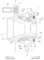
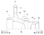
- FIG. 1 is a cross-sectional view showing an example of a hub unit bearing that is the subject of the present invention.
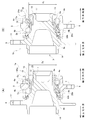
- FIG. 2A is a cross-sectional view of an example of the hub unit bearing before the caulking portion is formed
- FIG. 2B is a cross-sectional view of an example of the hub unit bearing after the caulking portion is formed. It is a figure.
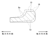
- FIG. 3 is a cross-sectional view of an inner ring constituting an example hub of the hub unit bearing.
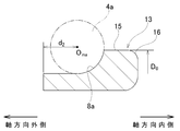
- FIG. 4 is a cross-sectional view showing an exaggerated state in which the inner ring expands as the crimped portion is formed.
- FIG. 1 is a cross-sectional view showing an example of a hub unit bearing that is the subject of the present invention.
- FIG. 2A is a cross-sectional view of an example of the hub unit bearing before the caulking portion is formed
- FIG. 2B is a cross-sectional view of an example of the hub unit bearing after the caulking portion is formed.
- FIG. 5 shows the amount of expansion of the inner ring due to external fitting into the hub ring constituting the hub in the hub of one example of the hub unit bearing, and forming a caulking portion on the hub ring. It is a graph which shows the relationship with the expansion amount of the said inner ring.
- FIG. 6 is a cross-sectional view showing the hub ring taken out.
- FIG. 7 is a cross-sectional view of an outer ring of an example of the hub unit bearing.
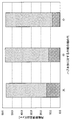
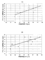
- FIG. 8A shows an expansion amount ⁇ D of the inner ring and an axial gap reduction amount ⁇ C from a single state before being fitted into the fitting cylinder portion of the hub ring in the hub of an example of the hub unit bearing.
- 8 (B) shows the expansion amount ⁇ D'of the inner ring from the state of being externally fitted to the fitting cylinder portion before forming the caulking portion, and the axial gap reduction amount ⁇ C. It is a graph which shows the relationship of.
- the hub unit bearing 1 to be the target of this example includes an outer ring 2, a hub 3, and rolling elements 4a and 4b.
- the outer ring 2 is made of a hard metal such as medium carbon steel.
- the outer ring 2 has a double-row outer ring tracks 5a and 5b on the inner peripheral surface, and has a stationary flange 6 protruding outward in the radial direction at an axial intermediate portion.
- the stationary flange 6 has support holes 7 penetrating in the axial direction at a plurality of locations in the circumferential direction in the middle portion in the radial direction.
- the outer ring 2 is supported and fixed to the suspension device by a support bolt inserted through the support hole 7 of the stationary flange 6, and does not rotate even when the wheel rotates.
- the hub 3 has double rows of inner ring tracks 8a and 8b on the outer peripheral surface, and is arranged coaxially with the outer ring 2 on the radial inside of the outer ring 2.
- the hub 3 has a rotary flange 9 protruding outward in the radial direction at a portion located outside the axial direction of the outer ring 2, and has a cylinder at the outer end in the axial direction. It has a shaped pilot unit 10.
- the rotary flange 9 has mounting holes 11 penetrating in the axial direction at a plurality of locations in the circumferential direction in the middle portion in the radial direction.
- a stud 12 is press-fitted (serration-fitted) into each of the mounting holes 11. That is, in this example, the mounting hole 11 is composed of a press-fitting hole.
- the “outside” in the axial direction means the left side of FIGS. 1 to 4, 6 and 7, which is the outside of the vehicle body when the hub unit bearing 1 is assembled to the automobile.
- the right side of FIGS. 1 to 4, 6 and 7, which is the center side of the vehicle body when the hub unit bearing 1 is assembled to the automobile is referred to as "inside" in the axial direction.
- the pilot portion 10 is inserted into a central hole that penetrates the central portion in the axial direction, and a plurality of locations in the circumferential direction of the radial intermediate portion.
- the hub nut is screwed into the tip of the stud 12 to be coupled to the rotating flange 9.
- the mounting hole of the rotary flange can also be formed by a female screw hole.
- the braking rotating body and the wheel are attached to the rotating flange by screwing the hub bolt through which the through hole provided in the braking rotating body and the through hole provided in the wheel are inserted into the mounting hole. Bond and fix.
- the hub 3 of this example includes an inner ring 13 and a hub wheel 14.
- the inner ring 13 is made of a hard metal such as bearing steel.
- the inner ring 13 has an inner ring orbit 8a on the inner side in the axial direction among the double-row inner ring orbits 8a and 8b at the axially intermediate portion of the outer peripheral surface.
- the inner ring 13 has an inner ring shoulder portion 15 on the outer peripheral surface adjacent to the inner ring orbit 8a on the inner side in the axial direction in the axial direction, and the end surface on the inner side in the axial direction and the inner ring shoulder portion 15
- the connecting portion has a chamfered portion 16 having an arcuate cross section.
- the inner ring shoulder portion 15 is formed of a cylindrical surface whose outer diameter dimension does not change in the axial direction.
- the hub wheel 14 is made of a hard metal such as medium carbon steel.
- the hub ring 14 has an inner ring raceway 8b on the outer side in the axial direction among the double-row inner ring raceways 8a and 8b at the axially intermediate portion of the outer peripheral surface.
- the hub ring 14 has a rotary flange 9 protruding outward in the radial direction at a portion located on the outer side in the axial direction with respect to the inner ring track 8b on the outer side in the axial direction, and has a cylindrical shape at an end portion on the outer side in the axial direction. It has a pilot unit 10 of the above.
- the hub ring 14 has a fitting cylinder portion 17 having a smaller outer diameter than a portion adjacent to the outer side in the axial direction and the inner ring 13 being externally fitted in a portion located inside the inner ring track 8b on the outer side in the axial direction.
- the hub ring 14 has a stepped surface 18 facing inward in the axial direction to which the end surface on the outer side in the axial direction of the inner ring 13 is abutted, and the fitting cylinder portion 17 from the inner end in the axial direction toward the outer side in the radial direction. It has a crimped portion 19 that is bent and presses the end face on the inner side in the axial direction of the inner ring 13.
- the inner ring 13 is press-fitted into the fitting cylinder portion 17 of the hub ring 14, and the crimped portion 19 presses the inner end surface of the inner ring 13 in the axial direction.
- the inner ring 13 is sandwiched between the stepped surface 18 and the crimped portion 19 from both sides in the axial direction.
- the hub 3 is configured by connecting and fixing the inner ring 13 and the hub ring 14.
- Each of the rolling elements 4a and 4b is made of a hard metal such as bearing steel or ceramics.
- a plurality of rolling elements 4a and 4b are rotatably arranged between the double-row outer ring tracks 5a and 5b and the double-row inner ring tracks 8a and 8b, respectively, while being held by the cages 20a and 20b.
- the hub 3 is rotatably supported inward in the radial direction of the outer ring 2.
- a preload is applied to the rolling elements 4a and 4b based on an axially outward force (axial force) applied from the inner ring 13.
- balls are used as rolling elements 4a and 4b, but tapered rollers can be used instead of balls.
- the pitch circle diameters of the rolling elements 4a and 4b in the inner row in the axial direction and the pitch circle diameters of the rolling elements 4a and 4b in the outer row in the axial direction are the same as each other. It can also be applied to PCD type hub unit bearings having different diameters in which the pitch circle diameter of the rolling elements in the inner row and the pitch circle diameters of the rolling elements in the outer row in the axial direction are different from each other.
- the hub unit bearing 1 exists between the inner peripheral surface of the outer ring 2 and the outer peripheral surface of the hub 3, and the rolling elements 4a and 4b are arranged on both sides of the cylindrical rolling element installation space 21 in the axial direction. Further provided with sealing devices 22a and 22b for closing the opening.
- the sealing device 22a on the inner side in the axial direction is a sealing ring having a slinger 23 that is externally fitted and fixed to the inner ring shoulder portion 15 of the inner ring 13 and a sealing lip that slides on the surface of the slinger 23 over the entire circumference. 24 and. That is, in this example, the sealing device 22a on the inner side in the axial direction is composed of a combination sealing ring.
- the axially inner sealing device that closes the axially inner opening of the rolling element installation space can also be configured by a bottomed cylindrical cover that is internally fitted and fixed to the outer ring.
- an encoder for detecting the number of rotations (rotational speed) of the wheels can be externally fitted and fixed to the shoulder portion of the inner ring of the inner ring.
- the sealing device 22b on the outer side in the axial direction has a seal lip that slides on the outer peripheral surface of the hub 3 or the inner side surface in the axial direction of the rotary flange 9 over the entire circumference. That is, in this example, the sealing device 22b on the outer side in the axial direction is composed of a sealing ring.
- the hub ring 14 is inserted into the outer ring assembly from the outside in the axial direction. Finally, the inner ring 13 is externally fitted into the fitting cylinder portion 17 of the hub ring 14 by press fitting.
- the procedure for assembling the hub unit bearing 1a is not particularly limited, and the order can be changed or the hub unit bearing 1a can be assembled at the same time as long as there is no contradiction.
- the tubular portion 25 projecting inward in the axial direction from the end face on the inner side in the axial direction of the inner ring 13 is radially outward.
- the crimped portion 19 is formed by plastically deforming the crimped portion 19.
- the inner ring 13 and the hub ring 14 are coupled and fixed to form the hub 3, and an appropriate preload is applied to the rolling elements 4a and 4b.
- the sealing device 22a on the inner side in the axial direction is mounted between the inner end portion in the axial direction of the outer ring 2 and the inner end portion in the axial direction of the hub 3, and the hub unit bearing 1 is completed.
- the method of forming the crimped portion 19 is not particularly limited.
- the caulking portion 19 presses, for example, a push die that is supported to rotate about a rotation axis inclined with respect to the central axis of the hub wheel 14 against the axially inner end of the tubular portion 25.
- the push die can be formed by rocking caulking that rotates around the central axis of the hub wheel 14.
- the caulking portion 19 can be formed by a press working (face pressing) in which the pressing die is pressed axially against the axially inner end of the tubular portion 25.
- the inner ring of the hub wheel 14 before being fitted to the fitting cylinder portion 17 of the hub wheel 14 is a single unit.
- the outer diameter dimension D 0 of 13 is measured.
- the outer diameter dimension D 0 of the inner ring shoulder portion 15 of the inner ring 13 is measured.
- the inner ring shoulder portion 15 is formed of a cylindrical surface having good shape accuracy to which the slinger 23 or the encoder of the sealing device 22a, which is a combination sealing ring, is fitted.
- the axial position of the portion of the inner ring shoulder portion 15 for measuring the outer diameter dimension D 0 is not particularly limited.
- the chamfered portion 16 It is preferable to measure the outer diameter dimension D 0 of the inner ring shoulder portion 15 in a range located outside in the axial direction and in a portion located inward in the axial direction as much as possible.
- the outer diameter dimension D 1 of the inner ring 13 is measured after the caulking portion 19 is formed and before the sealing device 22a on the inner side in the axial direction is attached.
- the axial position of the portion where the outer diameter dimension D 1 of the inner ring 13 is measured is the axial position of the portion where the outer diameter dimension D 0 of the inner ring 13 before being fitted into the fitting cylinder portion 17 of the hub ring 14 is measured. Same position.
- the axial gap reduction amount ⁇ C is obtained.
- the axial clearance reduction amount ⁇ C represents the reduction amount of the axial clearance of the hub unit bearing 1 due to the formation of the caulking portion 19.
- the relationship between the expansion amount ⁇ D of the inner ring 13 and the axial gap reduction amount ⁇ C is obtained in advance by an experiment or simulation, and is stored in the memory of the arithmetic unit as a map or an expression. That is, the expansion amount ⁇ D of the inner ring 13 is input to the arithmetic unit, and the axial gap reduction amount ⁇ C is obtained using the map or the formula.
- the preload applied to the rolling elements 4a and 4b is managed based on the axial gap reduction amount ⁇ C thus obtained. Specifically, it is determined whether or not the preload applied to the rolling elements 4a and 4b is within an appropriate range based on the axial clearance reduction amount ⁇ C, or the preload applied to the rolling elements 4a and 4b. To the proper range.
- the outer diameter dimension D 1 of the inner ring 13 in the crimped state and the inner ring 13 of a single body before being fitted into the fitting cylinder portion 17 of the hub ring 14 Based on the expansion amount ⁇ D, which is the difference from the outer diameter dimension D 0 of the hub unit bearing 1, the axial clearance reduction amount ⁇ C of the hub unit bearing 1 is obtained. That is, in this example, only the expansion amount of the inner ring 13 accompanying the formation of the crimped portion 19 (the expansion amount of the inner ring 13 between the state shown in FIG. 2A and the state shown in FIG. 2B) is sufficient.
- the inner ring 13 fitted to the fitting cylinder portion 17 of the hub ring 14 has an axially inner end surface of the inner ring 13 as an axis as shown by exaggerating with a chain line in FIG. 4 as the caulking portion 19 is formed. While shrinking the axial dimension so as to move outward in the direction, it expands outward in the radial direction.
- the fitting portion 19 is fitted regardless of the size of the tightening allowance of the inner ring 13 with respect to the fitting cylinder portion 17, as shown in FIG. It is considered that the expansion amount of the inner ring 13 from the single state before the outer fitting to the combined cylinder portion 17 becomes substantially constant, and the axial gap reduction amount ⁇ C also becomes substantially constant.
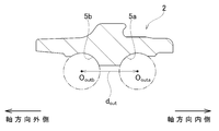
- the rolling element 4b in the outer row in the axial direction is rolled into contact with the inner ring track 8b on the outer side in the axial direction of the hub wheel 14.
- the first dimension d 1 which is the axial distance between the center O inb of the rolling element 4b and the stepped surface 18 is measured on the assumption that the rolling element 4b is moved.
- a second dimension d 2 is the axial distance between the axially outer end face of the inner ring 13 is measured.
- the first dimension d 1 and the second dimension d 2 are, for example, a curved surface portion having the same radius of curvature as 1/2 of the diameter (ball diameter) of the rolling elements 4a and 4b, and the curved surface portion that can be moved in perspective. It is possible to measure using a dedicated measuring instrument equipped with a simple stylus. That is, in the state of the hub ring 14 alone, the curved surface portion is brought into contact with the inner ring track 8b on the outer side in the axial direction, and the stylus is abutted against the stepped surface 18, so that the curvature center and the stepped surface of the curved surface portion are abutted. measuring the axial distance between 18 to obtain a first dimension d 1.
- the curved surface portion of the measuring instrument is brought into contact with the inner ring track 8a on the inner side in the axial direction, and the stylus is abutted against the end face on the outer side in the axial direction of the inner ring 13.
- the axial distance between the center of curvature of the curved surface portion and the axially outer end surface of the inner ring 13 is measured to obtain the second dimension d 2 .
- the second dimension d 2 and corrected taking into account the interference of the inner ring 13 relative to the fitting tube portion 17 to obtain a second dimension d 2 '.
- obtaining a trajectory 8a, the inner ring raceway distance d in is the distance 8b between.
- the center Oouta of the rolling elements 4a in the inner row in the axial direction measures the outer ring raceway distance d out is an axial distance between the center O outb of the rolling element 4b of the axially outer rows.
- the outer ring track spacing d out is, for example, a dedicated measuring instrument having the same radius of curvature as 1/2 of the diameter (ball diameter) of the rolling elements 4a and 4b, and having a pair of curved surfaces that can move in perspective with each other. Can be measured using. That is, in the state of the outer ring 2 alone, the pair of curved surface portions are brought into contact with the outer ring race tracks 5a and 5b of the double row, and the axial distance between the centers of curvature of the pair of curved surface portions is measured to measure the outer ring. Obtain the orbital interval d out.
- the initial axial gap C 0 in the state before the caulking portion 19 is formed is obtained.
- the center of the rolling element which is defined for measuring the first dimension, the second dimension, and the outer ring track spacing, is arbitrary on the central axis of the rolling element. Can be positioned. Specifically, for example, among the central axes of the rolling elements, the central position of the rolling elements in the axial direction can be set as the center of the rolling elements.
- the initial axial gap C 0 for obtaining the axial gap C 1 of the hub unit bearing 1b in the crimped state can be obtained by using a design value instead of obtaining by measurement.
- the preload can be set within an appropriate predetermined range.
- the combination of the outer ring 2, the inner ring 13, and the hub ring 14 for which the initial axial gap C 0 is appropriate can be selected from a plurality of outer rings 2, the inner ring 13, and the hub ring 14, or caulked. The machining load when forming the portion 19 can be adjusted.
- the relationship between the axial gap C 1 and the preload applied to the rolling elements 4a and 4b in the completed state of the hub unit bearing 1 is obtained in advance by experiments or simulations.
- a so-called third-generation hub unit bearing 1 including a hub 3 in which one inner ring 13 is coupled and fixed to the hub wheel 14 is targeted, but the present invention describes the shaft member. It is also possible to target a so-called 2.5th generation hub unit bearing having a hub formed by coupling and fixing a pair of inner rings.
- the hub ring is composed of a shaft member and an inner ring on the outer side in the axial direction of the pair of inner rings.
- the hub 3 (hub wheel 14) is solidly configured and the hub unit bearing 1 for the driven wheel is targeted has been described.
- the hub is located at the center thereof. It is also possible to target a hub unit bearing for a drive wheel, which has an engagement hole for engaging the drive shaft so as to be able to transmit torque.
- the expansion amount ⁇ D'of the inner ring 13 was set (comparative example)
- the correlation between the expansion amounts ⁇ D and ⁇ D'of the inner ring 13 and the axial gap reduction amount ⁇ C of the hub unit bearing 1 was obtained.
- the specifications of the hub unit bearing 1 were as follows.
- the caulking portion 19 has a push die supported to rotate about a rotation axis inclined with respect to the central axis of the hub wheel 14 at an axially inner end of the tubular portion 25 at 10.8 [kN]. ],
- the push die was formed by oscillating caulking to rotate (revolve) around the central axis of the hub wheel 14 at a rotational speed of 5 [s -1].
- the amount of decrease in the axial gap ⁇ C was calculated by obtaining the difference (C 0 ⁇ C 1 ) between the initial axial gap C 0 and the axial gap C 1 in the completed state.
- the outer diameter dimension D 0 of the inner ring 13 (inner ring shoulder portion 15) before being fitted into the fitting cylinder portion 17 and the inner ring 13 after forming the caulking portion 19
- the expansion amount ⁇ D of the inner ring 13 was obtained by measuring the outer diameter dimension D 1 of the above and calculating the difference (D 1 ⁇ D 0) between them.
- the expansion amount ⁇ D of the inner ring 13 and the axial gap reduction amount ⁇ C obtained in this way are plotted in FIG. 8 (A). Since the calculated values of the expansion amount ⁇ D and the axial gap reduction amount ⁇ C of the inner ring 13 were the same, the number of plots in FIG. 8 (A) was 12 (as a result of overlapping some plot points). It has become.
- the inner ring expansion amount ⁇ D' was obtained by calculating the difference (D 1 ⁇ D 0 ′) of the inner ring 13 from the outer diameter dimension D 1 after forming the crimped portion 19.
- the expansion amount ⁇ D'of the inner ring 13 thus obtained and the axial gap reduction amount ⁇ C are plotted in FIG. 8 (B). Since the calculated values of the expansion amount ⁇ D'and the axial gap reduction amount ⁇ C of the inner ring 13 were the same, the number of plots in FIG. 8B was 13 (as a result of overlapping some plot points). It is an individual.
- the correlation coefficient between the expansion amount ⁇ D'of the inner ring 13 and the axial gap reduction amount ⁇ C was 0.75, whereas in the example, the expansion amount ⁇ D of the inner ring 13 and the axial gap were found to be 0.75.
- the correlation coefficient with the amount of decrease ⁇ C was calculated, it was 0.81. That is, the expansion amount ⁇ D of the inner ring 13 from the single state before being fitted to the fitting cylinder portion 17 of the hub ring 14 is from the state of being outer-fitted to the fitting cylinder portion 17 before forming the caulking portion 19. It was found that the correlation with the axial gap reduction amount ⁇ C and the preload applied to the rolling elements 4a and 4b were stronger than the expansion amount ⁇ D'of the inner ring 13.
Landscapes
- Engineering & Computer Science (AREA)
- General Engineering & Computer Science (AREA)
- Mechanical Engineering (AREA)
- Rolling Contact Bearings (AREA)
- Support Of The Bearing (AREA)
- Mounting Of Bearings Or Others (AREA)
Priority Applications (3)
| Application Number | Priority Date | Filing Date | Title |
|---|---|---|---|
| EP20860319.1A EP4026627B1 (en) | 2019-09-06 | 2020-09-07 | Method for manufacturing a hub unit bearing |
| US17/639,999 US11852198B2 (en) | 2019-09-06 | 2020-09-07 | Hub unit bearing and method for manufacturing same |
| CN202080062266.2A CN114364891B (zh) | 2019-09-06 | 2020-09-07 | 轮毂单元轴承及其制造方法 |
Applications Claiming Priority (2)
| Application Number | Priority Date | Filing Date | Title |
|---|---|---|---|
| JP2019-162523 | 2019-09-06 | ||
| JP2019162523A JP7290086B2 (ja) | 2019-09-06 | 2019-09-06 | ハブユニット軸受およびその製造方法 |
Publications (1)
| Publication Number | Publication Date |
|---|---|
| WO2021045232A1 true WO2021045232A1 (ja) | 2021-03-11 |
Family
ID=74853367
Family Applications (1)
| Application Number | Title | Priority Date | Filing Date |
|---|---|---|---|
| PCT/JP2020/033827 Ceased WO2021045232A1 (ja) | 2019-09-06 | 2020-09-07 | ハブユニット軸受およびその製造方法 |
Country Status (5)
| Country | Link |
|---|---|
| US (1) | US11852198B2 (enExample) |
| EP (1) | EP4026627B1 (enExample) |
| JP (1) | JP7290086B2 (enExample) |
| CN (1) | CN114364891B (enExample) |
| WO (1) | WO2021045232A1 (enExample) |
Families Citing this family (1)
| Publication number | Priority date | Publication date | Assignee | Title |
|---|---|---|---|---|
| US12352648B2 (en) * | 2020-08-19 | 2025-07-08 | Ntn Corporation | Preload inspection method for bearing device for vehicle wheel |
Citations (5)
| Publication number | Priority date | Publication date | Assignee | Title |
|---|---|---|---|---|
| JP2002333016A (ja) * | 2001-05-10 | 2002-11-22 | Nsk Ltd | 車輪支持用転がり軸受ユニットの製造方法 |
| JP2003013979A (ja) | 2001-07-03 | 2003-01-15 | Nsk Ltd | 車輪駆動用軸受ユニット |
| JP2006046434A (ja) * | 2004-08-03 | 2006-02-16 | Ntn Corp | 車輪用軸受装置 |
| JP2006342877A (ja) * | 2005-06-08 | 2006-12-21 | Ntn Corp | 車輪軸受装置の隙間測定方法 |
| JP2018021613A (ja) * | 2016-08-04 | 2018-02-08 | 日本精工株式会社 | ハブユニット軸受の隙間測定方法 |
Family Cites Families (12)
| Publication number | Priority date | Publication date | Assignee | Title |
|---|---|---|---|---|
| JP4506028B2 (ja) * | 2001-05-08 | 2010-07-21 | 株式会社ジェイテクト | 複列転がり軸受の予圧測定方法および予圧測定装置 |
| JP4304943B2 (ja) * | 2002-09-10 | 2009-07-29 | 株式会社ジェイテクト | 転がり軸受装置 |
| CN100523531C (zh) * | 2003-06-03 | 2009-08-05 | Ntn株式会社 | 用于车轮的轴承装置 |
| JP4321714B2 (ja) * | 2004-08-10 | 2009-08-26 | Ntn株式会社 | 車輪用軸受装置 |
| JP4353870B2 (ja) * | 2004-08-12 | 2009-10-28 | Ntn株式会社 | 車輪用軸受装置のすきま測定方法 |
| JP2006144949A (ja) * | 2004-11-22 | 2006-06-08 | Ntn Corp | 車輪用軸受装置の軸受すきま測定方法 |
| JP4607081B2 (ja) * | 2006-09-22 | 2011-01-05 | Ntn株式会社 | 駆動車軸用軸受装置 |
| WO2012176787A1 (ja) * | 2011-06-20 | 2012-12-27 | Ntn株式会社 | 車輪用軸受装置およびその予圧管理方法 |
| JP5928144B2 (ja) * | 2012-05-09 | 2016-06-01 | 株式会社ジェイテクト | 車輪用ハブユニットの検査方法 |
| JP2014206191A (ja) * | 2013-04-11 | 2014-10-30 | Ntn株式会社 | 車輪用軸受装置の軸受すきま管理方法 |
| FR3008148B1 (fr) * | 2013-07-05 | 2016-05-27 | Skf Ab | Dispositif de palier a roulement, notamment pour colonne de direction |
| US9897138B2 (en) * | 2015-04-29 | 2018-02-20 | Aktiebolaget Skf | Method for preloading a hub bearing unit |
-
2019
- 2019-09-06 JP JP2019162523A patent/JP7290086B2/ja active Active
-
2020
- 2020-09-07 WO PCT/JP2020/033827 patent/WO2021045232A1/ja not_active Ceased
- 2020-09-07 EP EP20860319.1A patent/EP4026627B1/en active Active
- 2020-09-07 CN CN202080062266.2A patent/CN114364891B/zh active Active
- 2020-09-07 US US17/639,999 patent/US11852198B2/en active Active
Patent Citations (5)
| Publication number | Priority date | Publication date | Assignee | Title |
|---|---|---|---|---|
| JP2002333016A (ja) * | 2001-05-10 | 2002-11-22 | Nsk Ltd | 車輪支持用転がり軸受ユニットの製造方法 |
| JP2003013979A (ja) | 2001-07-03 | 2003-01-15 | Nsk Ltd | 車輪駆動用軸受ユニット |
| JP2006046434A (ja) * | 2004-08-03 | 2006-02-16 | Ntn Corp | 車輪用軸受装置 |
| JP2006342877A (ja) * | 2005-06-08 | 2006-12-21 | Ntn Corp | 車輪軸受装置の隙間測定方法 |
| JP2018021613A (ja) * | 2016-08-04 | 2018-02-08 | 日本精工株式会社 | ハブユニット軸受の隙間測定方法 |
Non-Patent Citations (1)
| Title |
|---|
| See also references of EP4026627A4 |
Also Published As
| Publication number | Publication date |
|---|---|
| JP7290086B2 (ja) | 2023-06-13 |
| US11852198B2 (en) | 2023-12-26 |
| CN114364891B (zh) | 2024-06-11 |
| EP4026627A4 (en) | 2023-09-27 |
| EP4026627A1 (en) | 2022-07-13 |
| EP4026627B1 (en) | 2024-06-12 |
| JP2021042762A (ja) | 2021-03-18 |
| US20220325751A1 (en) | 2022-10-13 |
| CN114364891A (zh) | 2022-04-15 |
Similar Documents
| Publication | Publication Date | Title |
|---|---|---|
| EP3928887B1 (en) | Method for manufacturing a hub bearing unit | |
| CN103703263B (zh) | 制造车轮轴承装置的方法 | |
| JP4345988B2 (ja) | 車輪用軸受装置 | |
| US8083598B2 (en) | Bearing device for wheel | |
| JP4969980B2 (ja) | 車輪用軸受装置の組立方法 | |
| JP4408251B2 (ja) | 車輪用軸受装置の軸受すきま測定方法 | |
| JP2021154391A (ja) | かしめアセンブリの製造方法、ハブユニット軸受の製造方法及び車両の製造方法 | |
| WO2021045232A1 (ja) | ハブユニット軸受およびその製造方法 | |
| US12103065B2 (en) | Staking assembly manufacturing method, hub unit bearing manufacturing method, and vehicle manufacturing method | |
| JP2003294033A (ja) | 複列転がり軸受およびその組立方法 | |
| JP2001088510A (ja) | 車輪軸受装置 | |
| JP2019206978A (ja) | ハブユニット軸受及びその組立方法 | |
| US20230400065A1 (en) | Producing method of bearing unit, producing method of machine, and producing method of vehicle | |
| JP2013092246A (ja) | 車輪用軸受装置 | |
| JP7049297B2 (ja) | 車輪用軸受装置の予圧検査方法 | |
| JP7440349B2 (ja) | 車輪支持用転がり軸受ユニット | |
| JP2021060076A (ja) | ハブユニット軸受 | |
| JP2008018767A (ja) | ドライブシャフトアセンブリ | |
| JP5891720B2 (ja) | ハブユニット軸受 | |
| JP2020097999A (ja) | ハブユニット軸受 | |
| JP2020098000A (ja) | ハブユニット軸受 | |
| JP2017096448A (ja) | ギヤ軸支持装置及び転がり軸受 | |
| JP2025053833A (ja) | ハブユニット軸受の予圧測定方法 | |
| JP2023137217A (ja) | アンギュラ玉軸受用保持器及びアンギュラ玉軸受 | |
| JP2014008838A (ja) | 車輪用軸受装置およびその組立方法 |
Legal Events
| Date | Code | Title | Description |
|---|---|---|---|
| 121 | Ep: the epo has been informed by wipo that ep was designated in this application |
Ref document number: 20860319 Country of ref document: EP Kind code of ref document: A1 |
|
| NENP | Non-entry into the national phase |
Ref country code: DE |
|
| ENP | Entry into the national phase |
Ref document number: 2020860319 Country of ref document: EP Effective date: 20220406 |