EP4026627B1 - Method for manufacturing a hub unit bearing - Google Patents
Method for manufacturing a hub unit bearing Download PDFInfo
- Publication number
- EP4026627B1 EP4026627B1 EP20860319.1A EP20860319A EP4026627B1 EP 4026627 B1 EP4026627 B1 EP 4026627B1 EP 20860319 A EP20860319 A EP 20860319A EP 4026627 B1 EP4026627 B1 EP 4026627B1
- Authority
- EP
- European Patent Office
- Prior art keywords
- inner ring
- hub
- unit bearing
- axial clearance
- axially
- Prior art date
- Legal status (The legal status is an assumption and is not a legal conclusion. Google has not performed a legal analysis and makes no representation as to the accuracy of the status listed.)
- Active
Links
Images


Classifications
-
- F—MECHANICAL ENGINEERING; LIGHTING; HEATING; WEAPONS; BLASTING
- F16—ENGINEERING ELEMENTS AND UNITS; GENERAL MEASURES FOR PRODUCING AND MAINTAINING EFFECTIVE FUNCTIONING OF MACHINES OR INSTALLATIONS; THERMAL INSULATION IN GENERAL
- F16C—SHAFTS; FLEXIBLE SHAFTS; ELEMENTS OR CRANKSHAFT MECHANISMS; ROTARY BODIES OTHER THAN GEARING ELEMENTS; BEARINGS
- F16C25/00—Bearings for exclusively rotary movement adjustable for wear or play
- F16C25/06—Ball or roller bearings
- F16C25/08—Ball or roller bearings self-adjusting
-
- F—MECHANICAL ENGINEERING; LIGHTING; HEATING; WEAPONS; BLASTING
- F16—ENGINEERING ELEMENTS AND UNITS; GENERAL MEASURES FOR PRODUCING AND MAINTAINING EFFECTIVE FUNCTIONING OF MACHINES OR INSTALLATIONS; THERMAL INSULATION IN GENERAL
- F16C—SHAFTS; FLEXIBLE SHAFTS; ELEMENTS OR CRANKSHAFT MECHANISMS; ROTARY BODIES OTHER THAN GEARING ELEMENTS; BEARINGS
- F16C43/00—Assembling bearings
- F16C43/04—Assembling rolling-contact bearings
-
- B—PERFORMING OPERATIONS; TRANSPORTING
- B21—MECHANICAL METAL-WORKING WITHOUT ESSENTIALLY REMOVING MATERIAL; PUNCHING METAL
- B21K—MAKING FORGED OR PRESSED METAL PRODUCTS, e.g. HORSE-SHOES, RIVETS, BOLTS OR WHEELS
- B21K1/00—Making machine elements
- B21K1/28—Making machine elements wheels; discs
- B21K1/40—Making machine elements wheels; discs hubs
-
- B—PERFORMING OPERATIONS; TRANSPORTING
- B21—MECHANICAL METAL-WORKING WITHOUT ESSENTIALLY REMOVING MATERIAL; PUNCHING METAL
- B21D—WORKING OR PROCESSING OF SHEET METAL OR METAL TUBES, RODS OR PROFILES WITHOUT ESSENTIALLY REMOVING MATERIAL; PUNCHING METAL
- B21D39/00—Application of procedures in order to connect objects or parts, e.g. coating with sheet metal otherwise than by plating; Tube expanders
-
- B—PERFORMING OPERATIONS; TRANSPORTING
- B21—MECHANICAL METAL-WORKING WITHOUT ESSENTIALLY REMOVING MATERIAL; PUNCHING METAL
- B21K—MAKING FORGED OR PRESSED METAL PRODUCTS, e.g. HORSE-SHOES, RIVETS, BOLTS OR WHEELS
- B21K25/00—Uniting components to form integral members, e.g. turbine wheels and shafts, caulks with inserts, with or without shaping of the components
-
- B—PERFORMING OPERATIONS; TRANSPORTING
- B60—VEHICLES IN GENERAL
- B60B—VEHICLE WHEELS; CASTORS; AXLES FOR WHEELS OR CASTORS; INCREASING WHEEL ADHESION
- B60B27/00—Hubs
- B60B27/0005—Hubs with ball bearings
-
- B—PERFORMING OPERATIONS; TRANSPORTING
- B60—VEHICLES IN GENERAL
- B60B—VEHICLE WHEELS; CASTORS; AXLES FOR WHEELS OR CASTORS; INCREASING WHEEL ADHESION
- B60B27/00—Hubs
- B60B27/001—Hubs with roller-bearings
-
- B—PERFORMING OPERATIONS; TRANSPORTING
- B60—VEHICLES IN GENERAL
- B60B—VEHICLE WHEELS; CASTORS; AXLES FOR WHEELS OR CASTORS; INCREASING WHEEL ADHESION
- B60B27/00—Hubs
- B60B27/0078—Hubs characterised by the fixation of bearings
- B60B27/0084—Hubs characterised by the fixation of bearings caulking to fix inner race
-
- F—MECHANICAL ENGINEERING; LIGHTING; HEATING; WEAPONS; BLASTING
- F16—ENGINEERING ELEMENTS AND UNITS; GENERAL MEASURES FOR PRODUCING AND MAINTAINING EFFECTIVE FUNCTIONING OF MACHINES OR INSTALLATIONS; THERMAL INSULATION IN GENERAL
- F16C—SHAFTS; FLEXIBLE SHAFTS; ELEMENTS OR CRANKSHAFT MECHANISMS; ROTARY BODIES OTHER THAN GEARING ELEMENTS; BEARINGS
- F16C19/00—Bearings with rolling contact, for exclusively rotary movement
- F16C19/02—Bearings with rolling contact, for exclusively rotary movement with bearing balls essentially of the same size in one or more circular rows
- F16C19/14—Bearings with rolling contact, for exclusively rotary movement with bearing balls essentially of the same size in one or more circular rows for both radial and axial load
- F16C19/18—Bearings with rolling contact, for exclusively rotary movement with bearing balls essentially of the same size in one or more circular rows for both radial and axial load with two or more rows of balls
-
- F—MECHANICAL ENGINEERING; LIGHTING; HEATING; WEAPONS; BLASTING
- F16—ENGINEERING ELEMENTS AND UNITS; GENERAL MEASURES FOR PRODUCING AND MAINTAINING EFFECTIVE FUNCTIONING OF MACHINES OR INSTALLATIONS; THERMAL INSULATION IN GENERAL
- F16C—SHAFTS; FLEXIBLE SHAFTS; ELEMENTS OR CRANKSHAFT MECHANISMS; ROTARY BODIES OTHER THAN GEARING ELEMENTS; BEARINGS
- F16C19/00—Bearings with rolling contact, for exclusively rotary movement
- F16C19/22—Bearings with rolling contact, for exclusively rotary movement with bearing rollers essentially of the same size in one or more circular rows, e.g. needle bearings
- F16C19/34—Bearings with rolling contact, for exclusively rotary movement with bearing rollers essentially of the same size in one or more circular rows, e.g. needle bearings for both radial and axial load
- F16C19/38—Bearings with rolling contact, for exclusively rotary movement with bearing rollers essentially of the same size in one or more circular rows, e.g. needle bearings for both radial and axial load with two or more rows of rollers
- F16C19/383—Bearings with rolling contact, for exclusively rotary movement with bearing rollers essentially of the same size in one or more circular rows, e.g. needle bearings for both radial and axial load with two or more rows of rollers with tapered rollers, i.e. rollers having essentially the shape of a truncated cone
- F16C19/385—Bearings with rolling contact, for exclusively rotary movement with bearing rollers essentially of the same size in one or more circular rows, e.g. needle bearings for both radial and axial load with two or more rows of rollers with tapered rollers, i.e. rollers having essentially the shape of a truncated cone with two rows, i.e. double-row tapered roller bearings
- F16C19/386—Bearings with rolling contact, for exclusively rotary movement with bearing rollers essentially of the same size in one or more circular rows, e.g. needle bearings for both radial and axial load with two or more rows of rollers with tapered rollers, i.e. rollers having essentially the shape of a truncated cone with two rows, i.e. double-row tapered roller bearings in O-arrangement
-
- F—MECHANICAL ENGINEERING; LIGHTING; HEATING; WEAPONS; BLASTING
- F16—ENGINEERING ELEMENTS AND UNITS; GENERAL MEASURES FOR PRODUCING AND MAINTAINING EFFECTIVE FUNCTIONING OF MACHINES OR INSTALLATIONS; THERMAL INSULATION IN GENERAL
- F16C—SHAFTS; FLEXIBLE SHAFTS; ELEMENTS OR CRANKSHAFT MECHANISMS; ROTARY BODIES OTHER THAN GEARING ELEMENTS; BEARINGS
- F16C35/00—Rigid support of bearing units; Housings, e.g. caps, covers
- F16C35/04—Rigid support of bearing units; Housings, e.g. caps, covers in the case of ball or roller bearings
- F16C35/06—Mounting or dismounting of ball or roller bearings; Fixing them onto shaft or in housing
- F16C35/063—Fixing them on the shaft
-
- F—MECHANICAL ENGINEERING; LIGHTING; HEATING; WEAPONS; BLASTING
- F16—ENGINEERING ELEMENTS AND UNITS; GENERAL MEASURES FOR PRODUCING AND MAINTAINING EFFECTIVE FUNCTIONING OF MACHINES OR INSTALLATIONS; THERMAL INSULATION IN GENERAL
- F16C—SHAFTS; FLEXIBLE SHAFTS; ELEMENTS OR CRANKSHAFT MECHANISMS; ROTARY BODIES OTHER THAN GEARING ELEMENTS; BEARINGS
- F16C19/00—Bearings with rolling contact, for exclusively rotary movement
- F16C19/02—Bearings with rolling contact, for exclusively rotary movement with bearing balls essentially of the same size in one or more circular rows
- F16C19/14—Bearings with rolling contact, for exclusively rotary movement with bearing balls essentially of the same size in one or more circular rows for both radial and axial load
- F16C19/18—Bearings with rolling contact, for exclusively rotary movement with bearing balls essentially of the same size in one or more circular rows for both radial and axial load with two or more rows of balls
- F16C19/181—Bearings with rolling contact, for exclusively rotary movement with bearing balls essentially of the same size in one or more circular rows for both radial and axial load with two or more rows of balls with angular contact
- F16C19/183—Bearings with rolling contact, for exclusively rotary movement with bearing balls essentially of the same size in one or more circular rows for both radial and axial load with two or more rows of balls with angular contact with two rows at opposite angles
- F16C19/184—Bearings with rolling contact, for exclusively rotary movement with bearing balls essentially of the same size in one or more circular rows for both radial and axial load with two or more rows of balls with angular contact with two rows at opposite angles in O-arrangement
- F16C19/186—Bearings with rolling contact, for exclusively rotary movement with bearing balls essentially of the same size in one or more circular rows for both radial and axial load with two or more rows of balls with angular contact with two rows at opposite angles in O-arrangement with three raceways provided integrally on parts other than race rings, e.g. third generation hubs
-
- F—MECHANICAL ENGINEERING; LIGHTING; HEATING; WEAPONS; BLASTING
- F16—ENGINEERING ELEMENTS AND UNITS; GENERAL MEASURES FOR PRODUCING AND MAINTAINING EFFECTIVE FUNCTIONING OF MACHINES OR INSTALLATIONS; THERMAL INSULATION IN GENERAL
- F16C—SHAFTS; FLEXIBLE SHAFTS; ELEMENTS OR CRANKSHAFT MECHANISMS; ROTARY BODIES OTHER THAN GEARING ELEMENTS; BEARINGS
- F16C2226/00—Joining parts; Fastening; Assembling or mounting parts
- F16C2226/50—Positive connections
- F16C2226/52—Positive connections with plastic deformation, e.g. caulking or staking
-
- F—MECHANICAL ENGINEERING; LIGHTING; HEATING; WEAPONS; BLASTING
- F16—ENGINEERING ELEMENTS AND UNITS; GENERAL MEASURES FOR PRODUCING AND MAINTAINING EFFECTIVE FUNCTIONING OF MACHINES OR INSTALLATIONS; THERMAL INSULATION IN GENERAL
- F16C—SHAFTS; FLEXIBLE SHAFTS; ELEMENTS OR CRANKSHAFT MECHANISMS; ROTARY BODIES OTHER THAN GEARING ELEMENTS; BEARINGS
- F16C2229/00—Setting preload
-
- F—MECHANICAL ENGINEERING; LIGHTING; HEATING; WEAPONS; BLASTING
- F16—ENGINEERING ELEMENTS AND UNITS; GENERAL MEASURES FOR PRODUCING AND MAINTAINING EFFECTIVE FUNCTIONING OF MACHINES OR INSTALLATIONS; THERMAL INSULATION IN GENERAL
- F16C—SHAFTS; FLEXIBLE SHAFTS; ELEMENTS OR CRANKSHAFT MECHANISMS; ROTARY BODIES OTHER THAN GEARING ELEMENTS; BEARINGS
- F16C2326/00—Articles relating to transporting
- F16C2326/01—Parts of vehicles in general
- F16C2326/02—Wheel hubs or castors
Definitions
- the present invention relates to a method for manufacturing a hub unit bearing for rotatably supporting a wheel and brake rotating body of an automobile with respect to a suspension device.
- a wheel and brake rotating body of an automobile are rotatably supported with respect to a suspension device by a hub unit bearing.
- a hub unit bearing includes an outer ring having double-row outer-raceways around the inner-circumferential surface, a hub having double-row inner-raceways around the outer-circumferential surface, and a plurality of rolling bodies arranged so as to be able to freely roll between the double-row outer-raceways and double-row inner-raceways.
- the hub includes an inner ring and a hub spindle.
- the inner ring in a state in which an end surface on an axially outboard side is provided in an axially intermediate section of the hub spindle and comes in contact with a stepped surface facing an axially inboard side, is externally fitted by a press fit with a tubular fitting portion that is provided in an axially inboard side portion of the hub spindle.
- a swaged portion that is formed by plastically deforming a tubular portion of the tubular fitting portion that protrudes further toward the axially inboard side than the end surface on the axially inboard side of the inner ring pushes the end surface on the axially inboard side of the inner ring.
- the inner ring and the hub spindle are joined and fixed together, and a preload is applied to the rolling bodies.
- JP 2003-013979A describes a method in which after the inner ring is externally fitted with the hub spindle, the outer-diameter dimension of the inner ring is measured before and after the swaged portion is formed, and the axial force that is applied to the inner ring from the swaged portion is controlled based on the amount of expansion of the outer-diameter dimension of the inner ring.
- the inner-raceway on the axially inboard side provided around the outer-circumferential surface of the inner ring is inclined in a direction toward the radially outer side while going toward the axially inboard side. Therefore, when the inner ring expands (outer-diameter dimension of the inner ring increases) as the inner ring is externally fitted with the hub spindle by press fitting, the rolling bodies in the row on the axially inboard side are press fitted toward the axially outboard side by the inner-raceway, and the preload applied to the rolling bodies increases.
- an object of the present invention is to provide a method for manufacturing a hub unit bearing capable of more accurately controlling a preload applied to the rolling bodies.
- the present invention is defined by the independent claim Preferred embodiment is defined in the dependent claim.
- the hub unit bearing includes an outer ring, a hub, and a plurality of rolling bodies.
- the outer ring is configured to be supported by and fastened to a suspension device so as not to rotate, and has double-row outer-raceways around an inner-circumferential surface thereof.
- the hub to which, in use, a wheel is fastened and that is configured to rotate together with the wheel, and has double-row inner-raceways around an outer-circumferential surface thereof.
- the plurality of rolling bodies are arranged between the double-row outer-raceways and the double-row inner-raceways, and a preload is applied thereto.
- the hub includes an inner ring having an inner-raceway on an axially inboard side of the double-row inner-raceways around an outer-circumferential surface thereof, and a hub spindle having an inner-raceway on an axially outboard side of the double-row inner-raceways around an outer-circumferential surface at an axially intermediate section thereof.
- the inner ring is externally fitted with a tubular fitting portion that is positioned further on the axially inboard side than the inner-raceway on the axially outboard side of the hub spindle, and the hub spindle has a swaged portion that is bent toward the radially outer side from an end section on the axially inboard side of the tubular fitting portion, and pushes the end surface on the axially inboard side of the inner ring.
- the inner ring and the hub spindle in a state in which the inner ring is externally fitted with a tubular fitting portion positioned further on the axially inboard side than the inner-raceway of the hub spindle that is on the axially outboard side, are joined and fastened together by pushing an end surface on the axially inboard side of the inner ring by a swaged portion formed by plastically deforming a tubular portion of the hub spindle that protrudes further toward the axially inboard side than an end surface on the axially inboard side of the inner ring outward in a radial direction.
- the method for manufacturing the hub unit bearing according to the present invention includes:
- an axial clearance of the hub unit bearing in a state after formation of the swaged portion is calculated by subtracting the amount of decrease in the axial clearance from an initial axial clearance, which is an axial clearance of the hub unit bearing in a state before formation of the swaged portion, and the preload is found in a completed state of the hub unit bearing based on that axial clearance.
- the preload can be set within a proper specified range by using the preload in the completed state of the hub unit bearing found based on the axial clearance as feedback.
- the preload is controlled based on an amount of decrease in the axial clearance found from an amount of expansion of the inner ring, which is the difference between the outer-diameter dimension of the inner ring after formation of the swaged portion and the outer-diameter dimension of the inner ring before being externally fitted with the tubular fitting portion.
- FIG. 1 to FIG. 7 An example of an embodiment of the present invention will be described referring FIG. 1 to FIG. 7 .
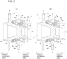
- a hub unit bearing 1 includes an outer ring 2, a hub 3, and rolling bodies 4a, 4b.
- the outer ring 2 is made of a hard metal such as medium carbon steel or the like.
- the outer ring 2 has double-row outer-raceways 5a, 5b around the inner-circumferential surface, and has a stationary flange 6 at an axially intermediate section that protrudes toward the radially outer side.
- the stationary flange 6 has support holes 7 that penetrate in the axial direction at a plurality of locations in the circumferential direction of a radially intermediate section.
- the outer ring 2 is supported by and fastened to a suspension device by support bolts that are inserted through the support holes 7 of the stationary flange 6, and does not rotate even when a wheel rotates.
- the hub 3 has double-row inner-raceways 8a, 8b around the outer-circumferential surface, and is coaxially arranged with the outer ring 2 on the radially inner side of the outer ring 2.
- the hub 3 has a rotating flange 9 located at a portion further on the axially outboard side than an end section on the axially outboard side of the outer ring 2 and protrudes toward the radially outer side, and has a cylindrical pilot section 10 at an end section on the other side in the axial direction.
- the rotating flange 9 has installation holes 11 that penetrate in the axial direction at a plurality of locations in the circumferential direction of a radially intermediate section.
- a stud 12 is press fitted (serration fit) in each of the installation holes 11.
- each installation hole 11 is composed of a press fitting hole.
- the "axially outboard side” is the outer side of the vehicle in a state in which the hub unit bearing 1 is assembled in the automobile, and is the left side in FIG. 1 to FIG. 4 , FIG. 6 and FIG. 7 .
- the right side in FIG. 1 to FIG. 4 , FIG. 6 and FIG. 7 which is the central side of the vehicle in a state in which the hub unit bearing 1 is assembled in the automobile, is referred to as the "axially inboard side".
- a brake rotating body such as a disc, drum or the like, and wheel are fixed to the rotating flange 9 by inserting the pilot section 10 through a center hole that penetrates in the axial direction of a center section thereof, and inserting the studs 12 through through holes that axially penetrate at a plurality of locations in the circumferential direction of the radially intermediate section and screwing hub nuts on the tip-end sections of the studs 12.
- the installation holes of the rotating flange may be composed of female screw holes.
- the brake rotating body and wheel are joined and fastened to the rotating flange by screwing hub bolts that are inserted through through holes provided in the brake rotating body and through through holes provided in the wheel into the installation holes.
- the hub 3 of this embodiment includes an inner ring 13 and a hub spindle 14.
- the inner ring 13 is made of a hard metal such as bearing steel or the like.
- the inner ring 13 has an inner-raceway 8a on the axially inboard side of the double-row inner-raceways 8a, 8b at an axially intermediate section of the outer-circumferential surface.
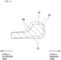
- the inner ring 13 has an inner-ring shoulder section 15 at a portion of the outer-circumferential surface adj acent to the axially inboard side of the inner-raceway 8a on the axially inboard side, and has a chamfered section 16 having an arc-shaped cross section at a connecting section of the end surface on the axially inboard side and the inner-ring shoulder section 15.
- the inner-ring shoulder section 15 is composed of a cylindrical surface of which the outer-diameter dimension does not change along the axial direction.
- the hub spindle 14 is made of a hard metal such as medium carbon steel or the like.
- the hub spindle 14 has an inner-raceway 8b on the axially outboard side of the double-row inner-raceways 8a, 8b at an axially intermediate section of the outer-circumferential surface.
- the hub spindle 14 has the rotating flange 9 that is located at a portion further on the axially outboard side than the inner-raceway 8b on the axially outboard side and that protrudes toward the radially outer side, and has the cylindrical shaped pilot section 10 at an end section on the axially outboard side.
- the hub spindle 14 has a tubular fitting portion 17 that is located at a portion further on the axially inboard side than the inner-raceway 8b on the axially outboard side, the outer diameter of the tubular fitting portion 17 is smaller than that of a portion adjacent to the axially outboard side, and the inner ring 13 externally fits with the tubular fitting portion 17.
- the hub spindle 14 has a stepped surface 18 that faces toward the axially inboard side and to which the end surface on the axially outboard side of the inner ring 13 comes in contact, and has a swaged portion 19 that is bent toward the radially outer side of the end section on the axially inboard side of the tubular fitting portion 17 and that pushes the end surface on the axially inboard side of the inner ring 13. That is, the hub 3 of this embodiment is such that the inner ring 13 externally fits with the tubular fitting portion 17 of the hub spindle 14 with a press fit, and the swaged portion 19 pushes the end surface on the axially inboard side of the inner ring 13. In other words, the inner ring 13 is held on both sides in the axial direction between the stepped surface 18 and the swaged portion 19. As a result, the hub 3 is configured by joining and fastening the inner ring 13 and the hub spindle 14.
- Each of the rolling bodies 4a, 4b is made of a hard metal such as bearing steel or the like, or is made of ceramic.
- the rolling bodies 4a, 4b are respectively arranged between the double-row outer-raceways 5a, 5b and the double-row inner-raceways 8a, 8b, and are respectively held by retainers 20a, 20b so as to be able to roll freely.
- the hub 3 is rotatably supported on the radially inner side of the outer ring 2.
- a preload is applied to the rolling bodies 4a, 4b due to a force (axial force) that is applied toward the axially outboard side from the inner ring 13.
- balls are used as the rolling bodies 4a, 4b; however, it is also possible to use tapered rollers instead of balls.
- the diameter of the pitch circle of the rolling bodies 4a, 4b in the row on the axially inboard side and the diameter of the pitch circle of the rolling bodies 4a, 4b in the row on the axially outboard side are the same as each other; however, the present invention can also be applied to an asymmetric type hub unit bearing in which the diameter of the pitch circle of the rolling bodies in the row on the axially inboard side and the diameter of the pitch circle of the rolling bodies in the row on the axially outboard side differ from each other.
- the hub unit bearing 1 further includes seal devices 22a, 22b that are located between the inner-circumferential surface of the outer ring 2 and the outer-circumferential surface of the hub 3, and that cover opening sections on both sides in the axial direction of a cylindrical rolling body installation space 21 where the rolling bodies 4a, 4b are arranged.
- the seal device 22a on the axially inboard side includes a slinger 23 that is externally fastened to the inner-ring shoulder section 15 of the inner ring 13, and a seal ring 24 having seal lips that come in sliding contact with the surface of the slinger 23 around the entire circumference.
- the seal device 22a on the axially inboard side is composed of a combination seal ring.
- a seal device on the axially inboard side for covering the opening section on the axially inboard side of the rolling body installation space could also be configured by a bottomed cylindrical shaped cover that is internally fixed to the outer ring. In this case, it is possible to externally fix an encoder for detecting the number of rotations (rotational speed) of the wheel to the inner-ring shoulder section of the inner ring as necessary.
- the seal device 22b on the axially outboard side has seal lips that come in sliding contact with the outer-circumferential surface of the hub 3 or the surface on the axially inboard side of the rotating flange 9 around the entire circumference.
- the seal device 22b on the axially outboard side is composed of a seal ring.
- the outer ring 2 and the rolling bodies 4a, 4b are arranged around the hub spindle 14, and the inner ring 13 is externally fitted with the tubular fitting portion 17 to assemble the hub unit bearing 1a to a state before forming the swaged portion 19.
- the rolling bodies 4a, 4b in a state of being held in the retainers 20a, 20b, for example, are arranged on the radially inner side of the double-row outer- raceways 5a, 5b of the outer ring 2, and the seal device 22b on the axially outboard side is internally fitted with the end section on the axially outboard side of the outer ring 2 to obtain an outer ring assembly.
- the hub spindle 14 is inserted into the outer ring assembly from the axially outboard side. Finally, the inner ring 13 is externally fitted with the tubular fitting portion 17 of the hub spindle 14 with a press fit.
- the procedure for assembling the hub unit bearing 1a is not particularly limited, and as long as no contradictions occur, the order of steps may be changed or may be performed at the same time.
- the swaged portion 19 is formed by plastically deforming a tubular portion 25 of the hub spindle 14 that protrudes further toward the axially inboard side than the end surface on the axially inboard side of the inner ring 13 toward the radially outer side.
- the inner ring 13 and the hub spindle 14 are joined and fixed together to form the hub 3, and a proper preload is applied to the rolling bodies 4a, 4b.
- the seal device 22a on the axially inboard side in between the end section on the axially inboard side of the outer ring 2 and the end section on the axially inboard side of the hub 3, the hub unit bearing 1 is completed.
- the method for forming the swaged portion 19 is not particularly limited.
- the swaged portion 19 could also be formed for example by pushing a die that is supported so as to be able to rotate around a rotation axis that is inclined with respect to the center axis of the hub spindle 14 against the end section on the axially inboard side of the tubular portion 25 while at the same time oscillating the die around the center axis of the hub spindle 14.
- the swaged portion 19 could be formed by stamping (deburring press) in which a die pushes the end section of the axially inboard side of the tubular portion 25 in the axial direction.
- the outer-diameter dimension D 0 of the inner ring 13 as a single body before being externally fitted with the tubular fitting portion 17 of the hub spindle 14 is measured. More specifically, the outer-diameter dimension D 0 of the inner-ring shoulder section 15 of the inner ring 13 is measured.
- the inner-ring shoulder section 15 is composed of a cylindrical surface having good shape accuracy to which the slinger 23 of the seal device 22a, which is a combination seal ring, or an encoder is externally fitted.
- the position in the axial direction of the portion of the inner-ring shoulder section 15 where the outer-diameter dimension D 0 is measured is not particularly limited. However, from the aspect of maintaining a large difference between the outer-diameter dimension D 0 of the inner ring 13 before being externally fitted with the hub spindle 14, and the outer-diameter dimension D 1 of the inner ring 13 after formation of the swaged portion 19, preferably the outer-diameter dimension D 0 of the inner-ring shoulder section 15 is measured within a range located further on the axially outboard side than the chamfered section 16 and located as much as possible on the axially inboard side.
- the outer-diameter dimension D 1 of the inner ring 13 is measured after the swaged portion 19 is formed and before the seal device 22a on the axially inboard side is installed.
- the position in the axial direction of the portion where the outer-diameter dimension D 1 of the inner ring 13 is measured is the same as the position in the axial direction of the portion where the outer-diameter dimension D 0 of the inner ring 13 before being externally fitted with the tubular fitting portion 17 of the hub spindle 14 is measured.
- An amount of decrease ⁇ C in the axial space is found based on the amount of expansion ⁇ D of the inner ring 13, which is the difference (D 1 - D 0 ) between the outer-diameter dimension D 1 of the inner ring 13 after the swaged portion 19 is formed (swaged state) and the outer-diameter dimension D 0 of the inner ring 13 before being externally fitted with the tubular fitting portion 17 of the hub spindle 14.
- the amount of decrease ⁇ C in the axial clearance represents the amount of decrease in the axial clearance of the hub unit bearing 1 that occurs when the swaged portion 19 is formed.
- the relation between the amount of expansion ⁇ D of the inner ring 13 and the amount of decrease ⁇ C in the axial clearance is found beforehand through experimentation and simulation, and is stored as a map or formula in memory of a computing device.
- the amount of expansion ⁇ D of the inner ring 13 is inputted to the computing device, and the amount of decrease ⁇ C in the axial clearance is found using the map or formula.
- the preload applied to the rolling bodies 4a, 4b is controlled based on the amount of decrease ⁇ C in the axial clearance that is found in this way. More specifically, determining whether or not the preload applied to the rolling bodies 4a, 4b is within a proper range, or setting the preload to be applied to the rolling bodies 4a, 4b to a proper range is performed based on the amount of decrease ⁇ C in the axial clearance.
- the amount of decrease ⁇ C in the axial clearance of the hub unit bearing 1 is found based on the amount of expansion ⁇ D, which is the difference between the outer-diameter dimension D 1 of the inner ring 13 in the swaged state and the outer-diameter dimension D 0 of the inner ring 13 as a single body before being externally fitted with the tubular fitting portion 17 of the hub spindle 14.
- ⁇ D the amount of expansion of the inner ring 13 due to the formation of the swaged portion 19 (the amount of expansion of the inner ring 13 from the state illustrated in FIG. 2A to the state illustrated in FIG.
- the reason for this will be described using FIG. 4 and FIG. 5 .
- the inner ring 13 that is externally fitted with the tubular fitting portion 17 of the hub spindle 14, as exaggeratedly illustrated by the chain line in FIG. 4 expands toward the radially outer side as the swaged portion 19 is formed, and as the dimension in the axial direction shrinks such that the end surface on the axially inboard side of the inner ring 13 moves toward the axially outboard side.
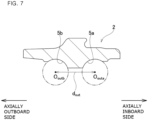
- a first dimension d 1 which is the interval in the axial direction between the center O inb of the rolling bodies 4b and the stepped surface 18, is measured for a case where it is presumed that the rolling bodies 4b in the row on the axially outboard side are in rolling contact with the inner-raceway 8b on the axially outboard side of the hub spindle 14. Moreover, as illustrated in FIG.
- a second dimension d 2 which is the interval in the axial direction between the center O ina of the rolling bodies 4a and the end surface on the axially outboard side of the inner ring 13, is measured for a case where it is presumed that the rolling bodies 4a of the row on the axially inboard side are in rolling contact with the inner-raceway 8a on the axially inboard side of the inner ring 13.
- the first dimension d 1 and the second dimension d 2 can be measured, for example, by using a dedicated measuring device that includes a curved surface section having a radius of curvature that is the same as 1/2 the diameter of the rolling bodies 4a, 4b (ball diameter), and a measuring element that is capable of moving toward or away from the curved surface section.
- the first dimension d 1 is obtained by bringing the curved surface section in contact with the inner-raceway 8b on the axially outboard side, and bringing the measuring element in contact with the stepped surface 18, and then measuring the interval in the axial direction between the center of curvature of the curved surface section and the stepped surface 18.
- the second dimension d 2 is obtained by bringing the curved surface section of the measuring device in contact with the inner-raceway 8a on the axially inboard side, and bringing the measuring element in contact with the end surface on the axially outboard side of the inner ring 13, and then measuring the interval in the axial direction between the center of curvature of the curved surface section and the end surface on the axially outboard side of the inner ring 13. Furthermore, a second dimension d 2 ' is obtained by correcting the second dimension d 2 in consideration of the interference of the inner ring 13 with respect to the tubular fitting portion 17.
- the corrected second dimension d 2 ' is obtained by reducing the second dimension d 2 by the amount that the center of the rolling bodies 4a of the row on the axially inboard side move toward the axially outboard side due to expansion of the inner-raceway 8a on the axially inboard side as the inner ring 13 is press fitted with the tubular fitting portion 17.
- an inner-raceway distance d in which is the distance between the double-row inner-raceways 8a, 8b in a state in which no axial force is applied by the swaged portion 19, is obtained.
- an outer-raceway distance d out which is the distance in the axial direction between the center O outa of the rolling bodies 4a of the row on the axially inboard side and the center O outb of the rolling bodies 4b of the row on the axially outboard side, is measured for a case in which it is presumed that the rolling bodies 4a, 4b are in rolling contact with the double-row outer-raceways 5a, 5b of the outer ring 2.
- the outer-raceway distance d out can be measured, for example, using a dedicated measuring device that includes a pair of curved surface sections having a radius of curvature that is the same as 1/2 the diameter of the rolling bodies 4a, 4b (ball diameter), and that are capable of moving toward or away from each other.
- a dedicated measuring device that includes a pair of curved surface sections having a radius of curvature that is the same as 1/2 the diameter of the rolling bodies 4a, 4b (ball diameter), and that are capable of moving toward or away from each other.
- the outer-raceway distance d out is obtained by bringing the pair of curved surface sections in contact with the double-row outer-raceways 5a, 5b and measuring the distance in the axial direction between the centers of curvature of the pair of curved surface sections.
- the initial axial clearance C 0 in the state before formation of the swaged portion 19 is obtained by finding the difference (d out - d in ) between the outer-raceway distance d out and the inner-raceway distance d in .
- the center of the rolling bodies that is specified for measuring the first dimension, the second dimension, and the outer-raceway distance can be set at any arbitrary position on the center axis of the rolling bodies. More specifically, of the center axis of the rolling bodies, an axially central position of the rolling bodies can be set as the center of the rolling bodies.
- the axial clearance C 1 of the hub unit bearing 1b in the swaged state is found by subtracting the amount of decrease ⁇ C in the axial clearance from the initial axial clearance C 0 .
- the preload to be applied to the rolling bodies 4a, 4b it is possible to set the preload to be applied to the rolling bodies 4a, 4b to a proper specified range by calculating the preload applied to the rolling bodies 4a, 4b in the completed state of the hub unit bearing 1 based on the axial clearance C 1 , and using the calculated preload as feedback. More specifically, it is possible to select from among a plurality of outer rings 2, inner rings 13, and hub spindle 14, a combination of an outer ring 2, an inner ring 13, and a hub spindle 14 for which the initial axial clearance C 0 will be proper, and it is possible to adjust the processing load when forming the swaged portion 19.
- the relation between the axial clearance C 1 and the preload applied to the rolling bodies 4a, 4b in the completed state of the hub unit bearing 1 can be found beforehand by experimentation, simulation or the like.
- a case is described of using a so-called third-generation hub unit bearing 1 that includes a hub 3 formed by joining and fixing one inner ring 13 to the hub spindle 14 as the object; however, in the present invention, it is also possible to use a so-called 2.5-generation hub unit bearing that includes a hub formed by joining and fixing a pair of inner rings to a shaft member as the object.
- a hub spindle is composed of a shaft member, and an inner ring on the axially outboard side of a pair of inner rings.
- the swaged portion 19 was formed by using a die that is supported so as to be able to rotate about a rotation axis that is inclined with respect to the center axis of the hub spindle 14 to push and swage the end section on the axially inboard side of the tubular portion 25 with a load of 10.8 [kN] while oscillating the die about the center axis of the hub spindle 14 with a rotating motion (revolving motion) at rotating speed of 5 [s -1 ].
- the initial axial clearance C 0 of the hub unit bearing 1 used in this experimentation was found by measuring the amount of displacement in the axial direction of the hub 3 while restricting the axial displacement of the outer ring 2 in the state illustrated in FIG. 2A .
- the axial clearance C 1 of the hub unit bearing 1 in the completed state was found by measuring the amount of axial displacement of the hub 3 while restricting the axial displacement of the outer ring 2 in the state illustrated in FIG. 2B .
- the amount of decrease ⁇ C in the axial clearance was calculated by finding the difference (C 0 - C 1 ) between the initial axial clearance C 0 and axial clearance C 1 in the complete state.
- the amount of expansion ⁇ D of the inner ring 13 was found by measuring the outer-diameter dimension D 0 of the inner ring 13 (inner-ring shoulder section 15) before being externally fitted with the tubular fitting portion 17, and the outer-diameter dimension D 1 of the inner ring 13 after formation of the swaged portion 19, and calculating the difference (D 1 - D 0 ) of these for fourteen hub unit bearings 1.
- the amount of expansion ⁇ D of the inner ring 13 found in this way, and the amount of decrease ⁇ C in the axial clearance are plotted in FIG. 8A .
- the outer-diameter dimension D 0 ' of the inner ring 13 after being fitted with the tubular fitting portion 17 and before formation of the swaged portion 19 was measured for fourteen hub unit bearings 1 in the same way as in the Example. Then, the amount of expansion ⁇ D' of the inner ring was found by calculating the difference (D 1 - D 0 ') with the outer-diameter dimension D 1 of the inner ring 13 after formation of the swaged portion 19. The amount of expansion ⁇ D' of the inner ring 13 found in this way, and the amount of decrease ⁇ C in the axial clearance are plotted in FIG. 8A .
- the amount of expansion ⁇ D of the inner ring 13 from the single body state before being externally fitted with the tubular fitting portion 17 of the hub spindle 14 has a stronger correlation with the amount of decrease ⁇ C in the axial clearance than the amount of expansion ⁇ D' of the inner ring 13 from the state of being externally fitted with the tubular fitting portion 17 and before formation of the swaged portion 19, and thus consequently, has a stronger correlation with the preload applied to the rolling bodies 4a, 4b.
Landscapes
- Engineering & Computer Science (AREA)
- General Engineering & Computer Science (AREA)
- Mechanical Engineering (AREA)
- Rolling Contact Bearings (AREA)
- Support Of The Bearing (AREA)
- Mounting Of Bearings Or Others (AREA)
Applications Claiming Priority (2)
| Application Number | Priority Date | Filing Date | Title |
|---|---|---|---|
| JP2019162523A JP7290086B2 (ja) | 2019-09-06 | 2019-09-06 | ハブユニット軸受およびその製造方法 |
| PCT/JP2020/033827 WO2021045232A1 (ja) | 2019-09-06 | 2020-09-07 | ハブユニット軸受およびその製造方法 |
Publications (3)
| Publication Number | Publication Date |
|---|---|
| EP4026627A1 EP4026627A1 (en) | 2022-07-13 |
| EP4026627A4 EP4026627A4 (en) | 2023-09-27 |
| EP4026627B1 true EP4026627B1 (en) | 2024-06-12 |
Family
ID=74853367
Family Applications (1)
| Application Number | Title | Priority Date | Filing Date |
|---|---|---|---|
| EP20860319.1A Active EP4026627B1 (en) | 2019-09-06 | 2020-09-07 | Method for manufacturing a hub unit bearing |
Country Status (5)
| Country | Link |
|---|---|
| US (1) | US11852198B2 (enExample) |
| EP (1) | EP4026627B1 (enExample) |
| JP (1) | JP7290086B2 (enExample) |
| CN (1) | CN114364891B (enExample) |
| WO (1) | WO2021045232A1 (enExample) |
Families Citing this family (1)
| Publication number | Priority date | Publication date | Assignee | Title |
|---|---|---|---|---|
| WO2022039203A1 (ja) * | 2020-08-19 | 2022-02-24 | Ntn株式会社 | 車輪用軸受装置の予圧検査方法 |
Family Cites Families (17)
| Publication number | Priority date | Publication date | Assignee | Title |
|---|---|---|---|---|
| JP4506028B2 (ja) * | 2001-05-08 | 2010-07-21 | 株式会社ジェイテクト | 複列転がり軸受の予圧測定方法および予圧測定装置 |
| JP2002333016A (ja) | 2001-05-10 | 2002-11-22 | Nsk Ltd | 車輪支持用転がり軸受ユニットの製造方法 |
| JP4710179B2 (ja) | 2001-07-03 | 2011-06-29 | 日本精工株式会社 | 車輪駆動輪用軸受ユニットの製造方法 |
| JP4304943B2 (ja) * | 2002-09-10 | 2009-07-29 | 株式会社ジェイテクト | 転がり軸受装置 |
| CN100523531C (zh) * | 2003-06-03 | 2009-08-05 | Ntn株式会社 | 用于车轮的轴承装置 |
| JP3917992B2 (ja) | 2004-08-03 | 2007-05-23 | Ntn株式会社 | 車輪用軸受装置 |
| JP4321714B2 (ja) * | 2004-08-10 | 2009-08-26 | Ntn株式会社 | 車輪用軸受装置 |
| JP4353870B2 (ja) * | 2004-08-12 | 2009-10-28 | Ntn株式会社 | 車輪用軸受装置のすきま測定方法 |
| JP2006144949A (ja) * | 2004-11-22 | 2006-06-08 | Ntn Corp | 車輪用軸受装置の軸受すきま測定方法 |
| JP2006342877A (ja) | 2005-06-08 | 2006-12-21 | Ntn Corp | 車輪軸受装置の隙間測定方法 |
| JP4607081B2 (ja) * | 2006-09-22 | 2011-01-05 | Ntn株式会社 | 駆動車軸用軸受装置 |
| WO2012176787A1 (ja) * | 2011-06-20 | 2012-12-27 | Ntn株式会社 | 車輪用軸受装置およびその予圧管理方法 |
| JP5928144B2 (ja) * | 2012-05-09 | 2016-06-01 | 株式会社ジェイテクト | 車輪用ハブユニットの検査方法 |
| JP2014206191A (ja) * | 2013-04-11 | 2014-10-30 | Ntn株式会社 | 車輪用軸受装置の軸受すきま管理方法 |
| FR3008148B1 (fr) * | 2013-07-05 | 2016-05-27 | Skf Ab | Dispositif de palier a roulement, notamment pour colonne de direction |
| US9897138B2 (en) * | 2015-04-29 | 2018-02-20 | Aktiebolaget Skf | Method for preloading a hub bearing unit |
| JP2018021613A (ja) | 2016-08-04 | 2018-02-08 | 日本精工株式会社 | ハブユニット軸受の隙間測定方法 |
-
2019
- 2019-09-06 JP JP2019162523A patent/JP7290086B2/ja active Active
-
2020
- 2020-09-07 US US17/639,999 patent/US11852198B2/en active Active
- 2020-09-07 CN CN202080062266.2A patent/CN114364891B/zh active Active
- 2020-09-07 WO PCT/JP2020/033827 patent/WO2021045232A1/ja not_active Ceased
- 2020-09-07 EP EP20860319.1A patent/EP4026627B1/en active Active
Also Published As
| Publication number | Publication date |
|---|---|
| JP7290086B2 (ja) | 2023-06-13 |
| EP4026627A4 (en) | 2023-09-27 |
| CN114364891B (zh) | 2024-06-11 |
| US11852198B2 (en) | 2023-12-26 |
| JP2021042762A (ja) | 2021-03-18 |
| EP4026627A1 (en) | 2022-07-13 |
| US20220325751A1 (en) | 2022-10-13 |
| WO2021045232A1 (ja) | 2021-03-11 |
| CN114364891A (zh) | 2022-04-15 |
Similar Documents
| Publication | Publication Date | Title |
|---|---|---|
| EP2722548B1 (en) | Method for producing wheel bearing device | |
| US8783963B2 (en) | Wheel bearing apparatus for a vehicle | |
| JP2010100156A5 (enExample) | ||
| JP2000289403A (ja) | 車輪支持用転がり軸受ユニットとその製造方法 | |
| EP3928887B1 (en) | Method for manufacturing a hub bearing unit | |
| EP4026627B1 (en) | Method for manufacturing a hub unit bearing | |
| CN113631298B (zh) | 铆接装配件的制造方法、及车辆的制造方法 | |
| EP3444491B1 (en) | Hub unit bearing | |
| US11273670B2 (en) | Hub unit bearing | |
| JP4078945B2 (ja) | 転がり軸受装置 | |
| EP4043744B1 (en) | Preload inspection method for bearing device for vehicle wheel. | |
| JPH11303859A (ja) | 回転速度検出装置付転がり軸受 | |
| JP2001088510A (ja) | 車輪軸受装置 | |
| EP1830097A1 (en) | Rolling bearing device | |
| JP5236097B2 (ja) | 車輪用軸受装置 | |
| JP5024850B2 (ja) | 車輪用軸受装置 | |
| JP2007263213A (ja) | 車輪用軸受装置 | |
| WO2007132552A1 (ja) | ブレーキロータ付き車輪用軸受装置 | |
| JP2007302202A (ja) | 車輪用軸受装置 | |
| JP2005297878A (ja) | ブレーキロータ付き車輪用軸受装置 | |
| JP2025053833A (ja) | ハブユニット軸受の予圧測定方法 | |
| JP2022134633A (ja) | 車輪用軸受装置 | |
| JP2001221241A (ja) | 軸受装置 | |
| JP2007085553A (ja) | 車輪軸受装置及びその製造方法 | |
| JP2007113719A (ja) | 車輪用軸受装置 |
Legal Events
| Date | Code | Title | Description |
|---|---|---|---|
| STAA | Information on the status of an ep patent application or granted ep patent |
Free format text: STATUS: THE INTERNATIONAL PUBLICATION HAS BEEN MADE |
|
| PUAI | Public reference made under article 153(3) epc to a published international application that has entered the european phase |
Free format text: ORIGINAL CODE: 0009012 |
|
| STAA | Information on the status of an ep patent application or granted ep patent |
Free format text: STATUS: REQUEST FOR EXAMINATION WAS MADE |
|
| 17P | Request for examination filed |
Effective date: 20220310 |
|
| AK | Designated contracting states |
Kind code of ref document: A1 Designated state(s): AL AT BE BG CH CY CZ DE DK EE ES FI FR GB GR HR HU IE IS IT LI LT LU LV MC MK MT NL NO PL PT RO RS SE SI SK SM TR |
|
| DAV | Request for validation of the european patent (deleted) | ||
| DAX | Request for extension of the european patent (deleted) | ||
| A4 | Supplementary search report drawn up and despatched |
Effective date: 20230828 |
|
| RIC1 | Information provided on ipc code assigned before grant |
Ipc: F16C 35/063 20060101ALI20230822BHEP Ipc: F16C 25/08 20060101ALI20230822BHEP Ipc: F16C 19/18 20060101ALI20230822BHEP Ipc: B21D 39/00 20060101AFI20230822BHEP |
|
| GRAP | Despatch of communication of intention to grant a patent |
Free format text: ORIGINAL CODE: EPIDOSNIGR1 |
|
| STAA | Information on the status of an ep patent application or granted ep patent |
Free format text: STATUS: GRANT OF PATENT IS INTENDED |
|
| INTG | Intention to grant announced |
Effective date: 20240322 |
|
| RIN1 | Information on inventor provided before grant (corrected) |
Inventor name: WATANABE, EISHO Inventor name: SAKAGUCHI, TAKASHI |
|
| GRAS | Grant fee paid |
Free format text: ORIGINAL CODE: EPIDOSNIGR3 |
|
| GRAA | (expected) grant |
Free format text: ORIGINAL CODE: 0009210 |
|
| STAA | Information on the status of an ep patent application or granted ep patent |
Free format text: STATUS: THE PATENT HAS BEEN GRANTED |
|
| AK | Designated contracting states |
Kind code of ref document: B1 Designated state(s): AL AT BE BG CH CY CZ DE DK EE ES FI FR GB GR HR HU IE IS IT LI LT LU LV MC MK MT NL NO PL PT RO RS SE SI SK SM TR |
|
| REG | Reference to a national code |
Ref country code: GB Ref legal event code: FG4D |
|
| REG | Reference to a national code |
Ref country code: CH Ref legal event code: EP |
|
| REG | Reference to a national code |
Ref country code: DE Ref legal event code: R096 Ref document number: 602020032456 Country of ref document: DE |
|
| REG | Reference to a national code |
Ref country code: IE Ref legal event code: FG4D |
|
| PG25 | Lapsed in a contracting state [announced via postgrant information from national office to epo] |
Ref country code: BG Free format text: LAPSE BECAUSE OF FAILURE TO SUBMIT A TRANSLATION OF THE DESCRIPTION OR TO PAY THE FEE WITHIN THE PRESCRIBED TIME-LIMIT Effective date: 20240612 |
|
| PG25 | Lapsed in a contracting state [announced via postgrant information from national office to epo] |
Ref country code: HR Free format text: LAPSE BECAUSE OF FAILURE TO SUBMIT A TRANSLATION OF THE DESCRIPTION OR TO PAY THE FEE WITHIN THE PRESCRIBED TIME-LIMIT Effective date: 20240612 Ref country code: FI Free format text: LAPSE BECAUSE OF FAILURE TO SUBMIT A TRANSLATION OF THE DESCRIPTION OR TO PAY THE FEE WITHIN THE PRESCRIBED TIME-LIMIT Effective date: 20240612 |
|
| REG | Reference to a national code |
Ref country code: LT Ref legal event code: MG9D |
|
| PG25 | Lapsed in a contracting state [announced via postgrant information from national office to epo] |
Ref country code: GR Free format text: LAPSE BECAUSE OF FAILURE TO SUBMIT A TRANSLATION OF THE DESCRIPTION OR TO PAY THE FEE WITHIN THE PRESCRIBED TIME-LIMIT Effective date: 20240913 |
|
| REG | Reference to a national code |
Ref country code: NL Ref legal event code: MP Effective date: 20240612 |
|
| PG25 | Lapsed in a contracting state [announced via postgrant information from national office to epo] |
Ref country code: ES Free format text: LAPSE BECAUSE OF FAILURE TO SUBMIT A TRANSLATION OF THE DESCRIPTION OR TO PAY THE FEE WITHIN THE PRESCRIBED TIME-LIMIT Effective date: 20240612 |
|
| PG25 | Lapsed in a contracting state [announced via postgrant information from national office to epo] |
Ref country code: LV Free format text: LAPSE BECAUSE OF FAILURE TO SUBMIT A TRANSLATION OF THE DESCRIPTION OR TO PAY THE FEE WITHIN THE PRESCRIBED TIME-LIMIT Effective date: 20240612 |
|
| PG25 | Lapsed in a contracting state [announced via postgrant information from national office to epo] |
Ref country code: NO Free format text: LAPSE BECAUSE OF FAILURE TO SUBMIT A TRANSLATION OF THE DESCRIPTION OR TO PAY THE FEE WITHIN THE PRESCRIBED TIME-LIMIT Effective date: 20240912 Ref country code: LV Free format text: LAPSE BECAUSE OF FAILURE TO SUBMIT A TRANSLATION OF THE DESCRIPTION OR TO PAY THE FEE WITHIN THE PRESCRIBED TIME-LIMIT Effective date: 20240612 Ref country code: HR Free format text: LAPSE BECAUSE OF FAILURE TO SUBMIT A TRANSLATION OF THE DESCRIPTION OR TO PAY THE FEE WITHIN THE PRESCRIBED TIME-LIMIT Effective date: 20240612 Ref country code: GR Free format text: LAPSE BECAUSE OF FAILURE TO SUBMIT A TRANSLATION OF THE DESCRIPTION OR TO PAY THE FEE WITHIN THE PRESCRIBED TIME-LIMIT Effective date: 20240913 Ref country code: FI Free format text: LAPSE BECAUSE OF FAILURE TO SUBMIT A TRANSLATION OF THE DESCRIPTION OR TO PAY THE FEE WITHIN THE PRESCRIBED TIME-LIMIT Effective date: 20240612 Ref country code: ES Free format text: LAPSE BECAUSE OF FAILURE TO SUBMIT A TRANSLATION OF THE DESCRIPTION OR TO PAY THE FEE WITHIN THE PRESCRIBED TIME-LIMIT Effective date: 20240612 Ref country code: BG Free format text: LAPSE BECAUSE OF FAILURE TO SUBMIT A TRANSLATION OF THE DESCRIPTION OR TO PAY THE FEE WITHIN THE PRESCRIBED TIME-LIMIT Effective date: 20240612 Ref country code: RS Free format text: LAPSE BECAUSE OF FAILURE TO SUBMIT A TRANSLATION OF THE DESCRIPTION OR TO PAY THE FEE WITHIN THE PRESCRIBED TIME-LIMIT Effective date: 20240912 |
|
| PG25 | Lapsed in a contracting state [announced via postgrant information from national office to epo] |
Ref country code: NL Free format text: LAPSE BECAUSE OF FAILURE TO SUBMIT A TRANSLATION OF THE DESCRIPTION OR TO PAY THE FEE WITHIN THE PRESCRIBED TIME-LIMIT Effective date: 20240612 |
|
| REG | Reference to a national code |
Ref country code: AT Ref legal event code: MK05 Ref document number: 1693797 Country of ref document: AT Kind code of ref document: T Effective date: 20240612 |
|
| PG25 | Lapsed in a contracting state [announced via postgrant information from national office to epo] |
Ref country code: NL Free format text: LAPSE BECAUSE OF FAILURE TO SUBMIT A TRANSLATION OF THE DESCRIPTION OR TO PAY THE FEE WITHIN THE PRESCRIBED TIME-LIMIT Effective date: 20240612 |
|
| PG25 | Lapsed in a contracting state [announced via postgrant information from national office to epo] |
Ref country code: PT Free format text: LAPSE BECAUSE OF FAILURE TO SUBMIT A TRANSLATION OF THE DESCRIPTION OR TO PAY THE FEE WITHIN THE PRESCRIBED TIME-LIMIT Effective date: 20241014 |
|
| PG25 | Lapsed in a contracting state [announced via postgrant information from national office to epo] |
Ref country code: PT Free format text: LAPSE BECAUSE OF FAILURE TO SUBMIT A TRANSLATION OF THE DESCRIPTION OR TO PAY THE FEE WITHIN THE PRESCRIBED TIME-LIMIT Effective date: 20241014 |
|
| PG25 | Lapsed in a contracting state [announced via postgrant information from national office to epo] |
Ref country code: PL Free format text: LAPSE BECAUSE OF FAILURE TO SUBMIT A TRANSLATION OF THE DESCRIPTION OR TO PAY THE FEE WITHIN THE PRESCRIBED TIME-LIMIT Effective date: 20240612 |
|
| PG25 | Lapsed in a contracting state [announced via postgrant information from national office to epo] |
Ref country code: EE Free format text: LAPSE BECAUSE OF FAILURE TO SUBMIT A TRANSLATION OF THE DESCRIPTION OR TO PAY THE FEE WITHIN THE PRESCRIBED TIME-LIMIT Effective date: 20240612 |
|
| PG25 | Lapsed in a contracting state [announced via postgrant information from national office to epo] |
Ref country code: AT Free format text: LAPSE BECAUSE OF FAILURE TO SUBMIT A TRANSLATION OF THE DESCRIPTION OR TO PAY THE FEE WITHIN THE PRESCRIBED TIME-LIMIT Effective date: 20240612 Ref country code: IS Free format text: LAPSE BECAUSE OF FAILURE TO SUBMIT A TRANSLATION OF THE DESCRIPTION OR TO PAY THE FEE WITHIN THE PRESCRIBED TIME-LIMIT Effective date: 20241012 |
|
| PG25 | Lapsed in a contracting state [announced via postgrant information from national office to epo] |
Ref country code: CZ Free format text: LAPSE BECAUSE OF FAILURE TO SUBMIT A TRANSLATION OF THE DESCRIPTION OR TO PAY THE FEE WITHIN THE PRESCRIBED TIME-LIMIT Effective date: 20240612 |
|
| PG25 | Lapsed in a contracting state [announced via postgrant information from national office to epo] |
Ref country code: RO Free format text: LAPSE BECAUSE OF FAILURE TO SUBMIT A TRANSLATION OF THE DESCRIPTION OR TO PAY THE FEE WITHIN THE PRESCRIBED TIME-LIMIT Effective date: 20240612 Ref country code: SK Free format text: LAPSE BECAUSE OF FAILURE TO SUBMIT A TRANSLATION OF THE DESCRIPTION OR TO PAY THE FEE WITHIN THE PRESCRIBED TIME-LIMIT Effective date: 20240612 |
|
| PG25 | Lapsed in a contracting state [announced via postgrant information from national office to epo] |
Ref country code: SM Free format text: LAPSE BECAUSE OF FAILURE TO SUBMIT A TRANSLATION OF THE DESCRIPTION OR TO PAY THE FEE WITHIN THE PRESCRIBED TIME-LIMIT Effective date: 20240612 |
|
| PG25 | Lapsed in a contracting state [announced via postgrant information from national office to epo] |
Ref country code: SM Free format text: LAPSE BECAUSE OF FAILURE TO SUBMIT A TRANSLATION OF THE DESCRIPTION OR TO PAY THE FEE WITHIN THE PRESCRIBED TIME-LIMIT Effective date: 20240612 Ref country code: SK Free format text: LAPSE BECAUSE OF FAILURE TO SUBMIT A TRANSLATION OF THE DESCRIPTION OR TO PAY THE FEE WITHIN THE PRESCRIBED TIME-LIMIT Effective date: 20240612 Ref country code: RO Free format text: LAPSE BECAUSE OF FAILURE TO SUBMIT A TRANSLATION OF THE DESCRIPTION OR TO PAY THE FEE WITHIN THE PRESCRIBED TIME-LIMIT Effective date: 20240612 Ref country code: PL Free format text: LAPSE BECAUSE OF FAILURE TO SUBMIT A TRANSLATION OF THE DESCRIPTION OR TO PAY THE FEE WITHIN THE PRESCRIBED TIME-LIMIT Effective date: 20240612 Ref country code: IS Free format text: LAPSE BECAUSE OF FAILURE TO SUBMIT A TRANSLATION OF THE DESCRIPTION OR TO PAY THE FEE WITHIN THE PRESCRIBED TIME-LIMIT Effective date: 20241012 Ref country code: EE Free format text: LAPSE BECAUSE OF FAILURE TO SUBMIT A TRANSLATION OF THE DESCRIPTION OR TO PAY THE FEE WITHIN THE PRESCRIBED TIME-LIMIT Effective date: 20240612 Ref country code: CZ Free format text: LAPSE BECAUSE OF FAILURE TO SUBMIT A TRANSLATION OF THE DESCRIPTION OR TO PAY THE FEE WITHIN THE PRESCRIBED TIME-LIMIT Effective date: 20240612 Ref country code: AT Free format text: LAPSE BECAUSE OF FAILURE TO SUBMIT A TRANSLATION OF THE DESCRIPTION OR TO PAY THE FEE WITHIN THE PRESCRIBED TIME-LIMIT Effective date: 20240612 |
|
| PG25 | Lapsed in a contracting state [announced via postgrant information from national office to epo] |
Ref country code: IT Free format text: LAPSE BECAUSE OF FAILURE TO SUBMIT A TRANSLATION OF THE DESCRIPTION OR TO PAY THE FEE WITHIN THE PRESCRIBED TIME-LIMIT Effective date: 20240612 |
|
| REG | Reference to a national code |
Ref country code: DE Ref legal event code: R097 Ref document number: 602020032456 Country of ref document: DE |
|
| PG25 | Lapsed in a contracting state [announced via postgrant information from national office to epo] |
Ref country code: DK Free format text: LAPSE BECAUSE OF FAILURE TO SUBMIT A TRANSLATION OF THE DESCRIPTION OR TO PAY THE FEE WITHIN THE PRESCRIBED TIME-LIMIT Effective date: 20240612 |
|
| PLBE | No opposition filed within time limit |
Free format text: ORIGINAL CODE: 0009261 |
|
| STAA | Information on the status of an ep patent application or granted ep patent |
Free format text: STATUS: NO OPPOSITION FILED WITHIN TIME LIMIT |
|
| PG25 | Lapsed in a contracting state [announced via postgrant information from national office to epo] |
Ref country code: MC Free format text: LAPSE BECAUSE OF FAILURE TO SUBMIT A TRANSLATION OF THE DESCRIPTION OR TO PAY THE FEE WITHIN THE PRESCRIBED TIME-LIMIT Effective date: 20240612 |
|
| REG | Reference to a national code |
Ref country code: CH Ref legal event code: PL |
|
| PG25 | Lapsed in a contracting state [announced via postgrant information from national office to epo] |
Ref country code: LU Free format text: LAPSE BECAUSE OF NON-PAYMENT OF DUE FEES Effective date: 20240907 |
|
| 26N | No opposition filed |
Effective date: 20250313 |
|
| GBPC | Gb: european patent ceased through non-payment of renewal fee |
Effective date: 20240912 |
|
| PG25 | Lapsed in a contracting state [announced via postgrant information from national office to epo] |
Ref country code: GB Free format text: LAPSE BECAUSE OF NON-PAYMENT OF DUE FEES Effective date: 20240912 |
|
| REG | Reference to a national code |
Ref country code: BE Ref legal event code: MM Effective date: 20240930 |
|
| PG25 | Lapsed in a contracting state [announced via postgrant information from national office to epo] |
Ref country code: BE Free format text: LAPSE BECAUSE OF NON-PAYMENT OF DUE FEES Effective date: 20240930 |
|
| PG25 | Lapsed in a contracting state [announced via postgrant information from national office to epo] |
Ref country code: FR Free format text: LAPSE BECAUSE OF NON-PAYMENT OF DUE FEES Effective date: 20240930 |
|
| PG25 | Lapsed in a contracting state [announced via postgrant information from national office to epo] |
Ref country code: CH Free format text: LAPSE BECAUSE OF NON-PAYMENT OF DUE FEES Effective date: 20240930 |
|
| PG25 | Lapsed in a contracting state [announced via postgrant information from national office to epo] |
Ref country code: IE Free format text: LAPSE BECAUSE OF NON-PAYMENT OF DUE FEES Effective date: 20240907 |
|
| PG25 | Lapsed in a contracting state [announced via postgrant information from national office to epo] |
Ref country code: SE Free format text: LAPSE BECAUSE OF FAILURE TO SUBMIT A TRANSLATION OF THE DESCRIPTION OR TO PAY THE FEE WITHIN THE PRESCRIBED TIME-LIMIT Effective date: 20240612 |
|
| PGFP | Annual fee paid to national office [announced via postgrant information from national office to epo] |
Ref country code: DE Payment date: 20250730 Year of fee payment: 6 |