WO2021045232A1 - Hub unit bearing and method for manufacturing same - Google Patents
Hub unit bearing and method for manufacturing same Download PDFInfo
- Publication number
- WO2021045232A1 WO2021045232A1 PCT/JP2020/033827 JP2020033827W WO2021045232A1 WO 2021045232 A1 WO2021045232 A1 WO 2021045232A1 JP 2020033827 W JP2020033827 W JP 2020033827W WO 2021045232 A1 WO2021045232 A1 WO 2021045232A1
- Authority
- WO
- WIPO (PCT)
- Prior art keywords
- inner ring
- hub
- ring
- axial direction
- axial
- Prior art date
Links
- 238000000034 method Methods 0.000 title claims abstract description 19
- 238000004519 manufacturing process Methods 0.000 title claims description 15
- 238000005096 rolling process Methods 0.000 claims abstract description 71
- 238000006049 ring expansion reaction Methods 0.000 claims abstract description 5
- 230000036316 preload Effects 0.000 claims description 43
- 230000009467 reduction Effects 0.000 claims description 31
- 230000002093 peripheral effect Effects 0.000 claims description 29
- 239000000725 suspension Substances 0.000 claims description 6
- 238000003825 pressing Methods 0.000 claims description 4
- 238000007789 sealing Methods 0.000 description 19
- 230000015572 biosynthetic process Effects 0.000 description 10
- 238000002474 experimental method Methods 0.000 description 7
- 229910000831 Steel Inorganic materials 0.000 description 4
- 238000006073 displacement reaction Methods 0.000 description 4
- 239000002184 metal Substances 0.000 description 4
- 239000010959 steel Substances 0.000 description 4
- 229910000954 Medium-carbon steel Inorganic materials 0.000 description 3
- 230000008859 change Effects 0.000 description 3
- 230000000052 comparative effect Effects 0.000 description 3
- 238000009434 installation Methods 0.000 description 3
- 239000000463 material Substances 0.000 description 3
- 230000000149 penetrating effect Effects 0.000 description 3
- 241001422033 Thestylus Species 0.000 description 2
- 238000002788 crimping Methods 0.000 description 2
- 230000000694 effects Effects 0.000 description 2
- 238000003754 machining Methods 0.000 description 2
- 230000008569 process Effects 0.000 description 2
- 238000004088 simulation Methods 0.000 description 2
- 239000000919 ceramic Substances 0.000 description 1
- 230000001276 controlling effect Effects 0.000 description 1
- 238000012937 correction Methods 0.000 description 1
- 230000008878 coupling Effects 0.000 description 1
- 238000010168 coupling process Methods 0.000 description 1
- 238000005859 coupling reaction Methods 0.000 description 1
- 238000013461 design Methods 0.000 description 1
- 230000006872 improvement Effects 0.000 description 1
- 238000007373 indentation Methods 0.000 description 1
- 238000005259 measurement Methods 0.000 description 1
- 230000001105 regulatory effect Effects 0.000 description 1
- 102220097517 rs876659265 Human genes 0.000 description 1
- 230000003068 static effect Effects 0.000 description 1
Images
Classifications
-
- F—MECHANICAL ENGINEERING; LIGHTING; HEATING; WEAPONS; BLASTING
- F16—ENGINEERING ELEMENTS AND UNITS; GENERAL MEASURES FOR PRODUCING AND MAINTAINING EFFECTIVE FUNCTIONING OF MACHINES OR INSTALLATIONS; THERMAL INSULATION IN GENERAL
- F16C—SHAFTS; FLEXIBLE SHAFTS; ELEMENTS OR CRANKSHAFT MECHANISMS; ROTARY BODIES OTHER THAN GEARING ELEMENTS; BEARINGS
- F16C25/00—Bearings for exclusively rotary movement adjustable for wear or play
- F16C25/06—Ball or roller bearings
- F16C25/08—Ball or roller bearings self-adjusting
-
- F—MECHANICAL ENGINEERING; LIGHTING; HEATING; WEAPONS; BLASTING
- F16—ENGINEERING ELEMENTS AND UNITS; GENERAL MEASURES FOR PRODUCING AND MAINTAINING EFFECTIVE FUNCTIONING OF MACHINES OR INSTALLATIONS; THERMAL INSULATION IN GENERAL
- F16C—SHAFTS; FLEXIBLE SHAFTS; ELEMENTS OR CRANKSHAFT MECHANISMS; ROTARY BODIES OTHER THAN GEARING ELEMENTS; BEARINGS
- F16C43/00—Assembling bearings
- F16C43/04—Assembling rolling-contact bearings
-
- B—PERFORMING OPERATIONS; TRANSPORTING
- B21—MECHANICAL METAL-WORKING WITHOUT ESSENTIALLY REMOVING MATERIAL; PUNCHING METAL
- B21K—MAKING FORGED OR PRESSED METAL PRODUCTS, e.g. HORSE-SHOES, RIVETS, BOLTS OR WHEELS
- B21K1/00—Making machine elements
- B21K1/28—Making machine elements wheels; discs
- B21K1/40—Making machine elements wheels; discs hubs
-
- B—PERFORMING OPERATIONS; TRANSPORTING
- B21—MECHANICAL METAL-WORKING WITHOUT ESSENTIALLY REMOVING MATERIAL; PUNCHING METAL
- B21D—WORKING OR PROCESSING OF SHEET METAL OR METAL TUBES, RODS OR PROFILES WITHOUT ESSENTIALLY REMOVING MATERIAL; PUNCHING METAL
- B21D39/00—Application of procedures in order to connect objects or parts, e.g. coating with sheet metal otherwise than by plating; Tube expanders
-
- B—PERFORMING OPERATIONS; TRANSPORTING
- B21—MECHANICAL METAL-WORKING WITHOUT ESSENTIALLY REMOVING MATERIAL; PUNCHING METAL
- B21K—MAKING FORGED OR PRESSED METAL PRODUCTS, e.g. HORSE-SHOES, RIVETS, BOLTS OR WHEELS
- B21K25/00—Uniting components to form integral members, e.g. turbine wheels and shafts, caulks with inserts, with or without shaping of the components
-
- B—PERFORMING OPERATIONS; TRANSPORTING
- B60—VEHICLES IN GENERAL
- B60B—VEHICLE WHEELS; CASTORS; AXLES FOR WHEELS OR CASTORS; INCREASING WHEEL ADHESION
- B60B27/00—Hubs
- B60B27/0005—Hubs with ball bearings
-
- B—PERFORMING OPERATIONS; TRANSPORTING
- B60—VEHICLES IN GENERAL
- B60B—VEHICLE WHEELS; CASTORS; AXLES FOR WHEELS OR CASTORS; INCREASING WHEEL ADHESION
- B60B27/00—Hubs
- B60B27/001—Hubs with roller-bearings
-
- B—PERFORMING OPERATIONS; TRANSPORTING
- B60—VEHICLES IN GENERAL
- B60B—VEHICLE WHEELS; CASTORS; AXLES FOR WHEELS OR CASTORS; INCREASING WHEEL ADHESION
- B60B27/00—Hubs
- B60B27/0078—Hubs characterised by the fixation of bearings
- B60B27/0084—Hubs characterised by the fixation of bearings caulking to fix inner race
-
- F—MECHANICAL ENGINEERING; LIGHTING; HEATING; WEAPONS; BLASTING
- F16—ENGINEERING ELEMENTS AND UNITS; GENERAL MEASURES FOR PRODUCING AND MAINTAINING EFFECTIVE FUNCTIONING OF MACHINES OR INSTALLATIONS; THERMAL INSULATION IN GENERAL
- F16C—SHAFTS; FLEXIBLE SHAFTS; ELEMENTS OR CRANKSHAFT MECHANISMS; ROTARY BODIES OTHER THAN GEARING ELEMENTS; BEARINGS
- F16C19/00—Bearings with rolling contact, for exclusively rotary movement
- F16C19/02—Bearings with rolling contact, for exclusively rotary movement with bearing balls essentially of the same size in one or more circular rows
- F16C19/14—Bearings with rolling contact, for exclusively rotary movement with bearing balls essentially of the same size in one or more circular rows for both radial and axial load
- F16C19/18—Bearings with rolling contact, for exclusively rotary movement with bearing balls essentially of the same size in one or more circular rows for both radial and axial load with two or more rows of balls
-
- F—MECHANICAL ENGINEERING; LIGHTING; HEATING; WEAPONS; BLASTING
- F16—ENGINEERING ELEMENTS AND UNITS; GENERAL MEASURES FOR PRODUCING AND MAINTAINING EFFECTIVE FUNCTIONING OF MACHINES OR INSTALLATIONS; THERMAL INSULATION IN GENERAL
- F16C—SHAFTS; FLEXIBLE SHAFTS; ELEMENTS OR CRANKSHAFT MECHANISMS; ROTARY BODIES OTHER THAN GEARING ELEMENTS; BEARINGS
- F16C19/00—Bearings with rolling contact, for exclusively rotary movement
- F16C19/22—Bearings with rolling contact, for exclusively rotary movement with bearing rollers essentially of the same size in one or more circular rows, e.g. needle bearings
- F16C19/34—Bearings with rolling contact, for exclusively rotary movement with bearing rollers essentially of the same size in one or more circular rows, e.g. needle bearings for both radial and axial load
- F16C19/38—Bearings with rolling contact, for exclusively rotary movement with bearing rollers essentially of the same size in one or more circular rows, e.g. needle bearings for both radial and axial load with two or more rows of rollers
- F16C19/383—Bearings with rolling contact, for exclusively rotary movement with bearing rollers essentially of the same size in one or more circular rows, e.g. needle bearings for both radial and axial load with two or more rows of rollers with tapered rollers, i.e. rollers having essentially the shape of a truncated cone
- F16C19/385—Bearings with rolling contact, for exclusively rotary movement with bearing rollers essentially of the same size in one or more circular rows, e.g. needle bearings for both radial and axial load with two or more rows of rollers with tapered rollers, i.e. rollers having essentially the shape of a truncated cone with two rows, i.e. double-row tapered roller bearings
- F16C19/386—Bearings with rolling contact, for exclusively rotary movement with bearing rollers essentially of the same size in one or more circular rows, e.g. needle bearings for both radial and axial load with two or more rows of rollers with tapered rollers, i.e. rollers having essentially the shape of a truncated cone with two rows, i.e. double-row tapered roller bearings in O-arrangement
-
- F—MECHANICAL ENGINEERING; LIGHTING; HEATING; WEAPONS; BLASTING
- F16—ENGINEERING ELEMENTS AND UNITS; GENERAL MEASURES FOR PRODUCING AND MAINTAINING EFFECTIVE FUNCTIONING OF MACHINES OR INSTALLATIONS; THERMAL INSULATION IN GENERAL
- F16C—SHAFTS; FLEXIBLE SHAFTS; ELEMENTS OR CRANKSHAFT MECHANISMS; ROTARY BODIES OTHER THAN GEARING ELEMENTS; BEARINGS
- F16C35/00—Rigid support of bearing units; Housings, e.g. caps, covers
- F16C35/04—Rigid support of bearing units; Housings, e.g. caps, covers in the case of ball or roller bearings
- F16C35/06—Mounting or dismounting of ball or roller bearings; Fixing them onto shaft or in housing
- F16C35/063—Fixing them on the shaft
-
- F—MECHANICAL ENGINEERING; LIGHTING; HEATING; WEAPONS; BLASTING
- F16—ENGINEERING ELEMENTS AND UNITS; GENERAL MEASURES FOR PRODUCING AND MAINTAINING EFFECTIVE FUNCTIONING OF MACHINES OR INSTALLATIONS; THERMAL INSULATION IN GENERAL
- F16C—SHAFTS; FLEXIBLE SHAFTS; ELEMENTS OR CRANKSHAFT MECHANISMS; ROTARY BODIES OTHER THAN GEARING ELEMENTS; BEARINGS
- F16C19/00—Bearings with rolling contact, for exclusively rotary movement
- F16C19/02—Bearings with rolling contact, for exclusively rotary movement with bearing balls essentially of the same size in one or more circular rows
- F16C19/14—Bearings with rolling contact, for exclusively rotary movement with bearing balls essentially of the same size in one or more circular rows for both radial and axial load
- F16C19/18—Bearings with rolling contact, for exclusively rotary movement with bearing balls essentially of the same size in one or more circular rows for both radial and axial load with two or more rows of balls
- F16C19/181—Bearings with rolling contact, for exclusively rotary movement with bearing balls essentially of the same size in one or more circular rows for both radial and axial load with two or more rows of balls with angular contact
- F16C19/183—Bearings with rolling contact, for exclusively rotary movement with bearing balls essentially of the same size in one or more circular rows for both radial and axial load with two or more rows of balls with angular contact with two rows at opposite angles
- F16C19/184—Bearings with rolling contact, for exclusively rotary movement with bearing balls essentially of the same size in one or more circular rows for both radial and axial load with two or more rows of balls with angular contact with two rows at opposite angles in O-arrangement
- F16C19/186—Bearings with rolling contact, for exclusively rotary movement with bearing balls essentially of the same size in one or more circular rows for both radial and axial load with two or more rows of balls with angular contact with two rows at opposite angles in O-arrangement with three raceways provided integrally on parts other than race rings, e.g. third generation hubs
-
- F—MECHANICAL ENGINEERING; LIGHTING; HEATING; WEAPONS; BLASTING
- F16—ENGINEERING ELEMENTS AND UNITS; GENERAL MEASURES FOR PRODUCING AND MAINTAINING EFFECTIVE FUNCTIONING OF MACHINES OR INSTALLATIONS; THERMAL INSULATION IN GENERAL
- F16C—SHAFTS; FLEXIBLE SHAFTS; ELEMENTS OR CRANKSHAFT MECHANISMS; ROTARY BODIES OTHER THAN GEARING ELEMENTS; BEARINGS
- F16C2226/00—Joining parts; Fastening; Assembling or mounting parts
- F16C2226/50—Positive connections
- F16C2226/52—Positive connections with plastic deformation, e.g. caulking or staking
-
- F—MECHANICAL ENGINEERING; LIGHTING; HEATING; WEAPONS; BLASTING
- F16—ENGINEERING ELEMENTS AND UNITS; GENERAL MEASURES FOR PRODUCING AND MAINTAINING EFFECTIVE FUNCTIONING OF MACHINES OR INSTALLATIONS; THERMAL INSULATION IN GENERAL
- F16C—SHAFTS; FLEXIBLE SHAFTS; ELEMENTS OR CRANKSHAFT MECHANISMS; ROTARY BODIES OTHER THAN GEARING ELEMENTS; BEARINGS
- F16C2229/00—Setting preload
-
- F—MECHANICAL ENGINEERING; LIGHTING; HEATING; WEAPONS; BLASTING
- F16—ENGINEERING ELEMENTS AND UNITS; GENERAL MEASURES FOR PRODUCING AND MAINTAINING EFFECTIVE FUNCTIONING OF MACHINES OR INSTALLATIONS; THERMAL INSULATION IN GENERAL
- F16C—SHAFTS; FLEXIBLE SHAFTS; ELEMENTS OR CRANKSHAFT MECHANISMS; ROTARY BODIES OTHER THAN GEARING ELEMENTS; BEARINGS
- F16C2326/00—Articles relating to transporting
- F16C2326/01—Parts of vehicles in general
- F16C2326/02—Wheel hubs or castors
Definitions
- the present invention relates to a hub unit bearing for rotatably supporting an automobile wheel and a rotating body for braking with respect to a suspension device, and a method for manufacturing the same.
- the wheels of the automobile and the rotating body for braking are rotatably supported by the hub unit bearings with respect to the suspension device.
- the hub unit bearing rolls between an outer ring having a double-row outer ring raceway on the inner peripheral surface, a hub having a double-row inner ring raceway on the outer peripheral surface, and the double-row outer ring raceway and the double-row inner ring raceway. It is provided with a plurality of rolling elements arranged so as to be movable.
- the hub includes an inner ring and a hub ring.
- the inner ring is provided on the axially inner portion of the hub wheel in a state where the axially outer end surface is provided on the axially intermediate portion of the hub ring and is abutted against the stepped surface facing the axially inward side. It is externally fitted to the fitting cylinder by press fitting.
- the caulking portion formed by plastically deforming the tubular portion of the fitting tubular portion that protrudes inward in the axial direction from the axially inner end surface of the inner ring is formed by plastically deforming the inner ring in the radial direction.
- the end face on the inner side in the axial direction of the inner ring is pressed.
- the inner ring and the hub ring are coupled and fixed, and a preload is applied to the rolling element.
- the life of the hub unit bearing will be shortened or the dynamic torque (rotational resistance) of the hub unit bearing will increase if the preload is too large.
- the running performance of the vehicle deteriorates, and conversely, if the preload is too small, the moment rigidity becomes insufficient and the maneuverability of the vehicle deteriorates. Therefore, strict control is required for the preload applied to the rolling element.
- the inner ring orbit on the inner side of the inner ring provided on the outer peripheral surface of the inner ring is inclined toward the outer side in the radial direction toward the inner side in the axial direction. Therefore, when the inner ring expands (the outer diameter dimension of the inner ring increases) as the inner ring is fitted into the hub ring by press fitting, the rolling elements in the inner row in the axial direction move outward in the axial direction due to the inner ring trajectory. The preload applied to the rolling element is increased by being pressed toward the rolling element.
- the preload applied to the rolling element is affected not only by the amount of expansion of the inner ring due to the formation of the crimped portion but also by the amount of expansion due to the press fitting of the inner ring into the hub ring.
- the amount of expansion of the inner ring due to press-fitting into the hub ring changes based on the tightening allowance of the inner peripheral surface of the inner ring with respect to the outer peripheral surface of the fitting cylinder portion.
- the method described in Japanese Patent Application Laid-Open No. 2003-13979 does not consider the influence of the amount of expansion due to the press-fitting of the inner ring into the hub ring on the preload applied to the rolling element, and manages the preload more accurately. From the aspect of doing so, it can be said that there is room for further improvement.
- an object of the present invention is to realize a hub unit bearing capable of more accurately controlling the preload applied to the rolling element, and a method for manufacturing the hub unit bearing.
- the hub unit bearing which is the object of the present invention includes an outer ring, a hub, and a plurality of rolling elements.
- the outer ring has a double-row outer ring track on the inner peripheral surface, is supported and fixed to the suspension device, and does not rotate.
- the hub has a double-row inner ring track on the outer peripheral surface, and the wheels are fixed and rotate together with the wheels.
- the plurality of rolling elements are rotatably arranged between the outer ring track of the double row and the inner ring track of the double row, and a preload is applied.
- the hub has an inner ring having an inner ring track on the outer peripheral surface in the axial direction of the inner ring track of the double row, and an inner ring on the outer peripheral surface of the intermediate portion in the axial direction on the outer ring in the axial direction of the inner ring track of the double row. It is equipped with a hub wheel having a track.
- the inner ring is fitted onto a fitting cylinder portion of the hub ring located axially inside the inner ring track on the outer side in the axial direction, and the hub ring is an axially inner end of the fitting cylinder portion. It has a caulking portion that bends outward in the radial direction from the portion and presses the end face on the inner side in the axial direction of the inner ring. That is, the inner ring and the hub ring are the hub wheels in a state in which the inner ring is outerly fitted to a fitting cylinder portion located axially inside the inner ring track on the outer side in the axial direction.
- the inner end face of the inner ring is pressed by a caulking portion formed by plastically deforming a tubular portion protruding inward in the axial direction from the inner end surface of the inner ring in the axial direction. It is bonded and fixed with.
- the method for manufacturing a hub unit bearing according to an embodiment of the present invention is as follows.
- An outer fitting step of outerly fitting the inner ring to the fitting cylinder portion A crimping step in which the tubular portion is plastically deformed outward in the radial direction to form the caulking portion. After the caulking portion is formed, the outer diameter dimension of the inner ring is measured, and the post-caulking step is performed.
- the outer fitting step With Based on the inner ring expansion amount, which is the difference between the outer diameter dimension of the inner ring after forming the crimped portion and the outer diameter dimension of the inner ring before outer fitting to the fitting cylinder portion, the outer fitting step The amount of reduction in the axial gap reduced by the caulking step was determined. The preload is controlled based on the amount of reduction in the axial gap.
- the arrangement process and the outer fitting process can be performed at the same time.
- the amount of reduction in the axial gap is subtracted from the initial axial gap which is the axial gap of the hub unit bearing in the state before the caulking portion is formed, and the caulking portion is formed.
- the axial gap of the hub unit bearing in the state after forming the above can be calculated, and the preload in the completed state of the hub unit bearing can be obtained based on the axial gap.
- the preload in the completed state of the hub unit bearing obtained based on the axial gap can be fed back to set the preload within a predetermined range.
- the hub unit bearing according to the embodiment of the present invention has the outer diameter dimension of the inner ring measured after forming the crimped portion and the outer diameter of the inner ring measured before the inner ring is fitted into the fitting cylinder portion.
- the preload is controlled based on the amount of decrease in the axial gap obtained from the amount of expansion of the inner ring, which is the difference from the diameter dimension.
- the preload applied to the rolling element can be managed more accurately.
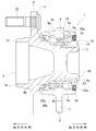
- FIG. 1 is a cross-sectional view showing an example of a hub unit bearing that is the subject of the present invention.
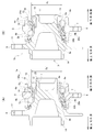
- FIG. 2A is a cross-sectional view of an example of the hub unit bearing before the caulking portion is formed
- FIG. 2B is a cross-sectional view of an example of the hub unit bearing after the caulking portion is formed. It is a figure.
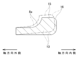
- FIG. 3 is a cross-sectional view of an inner ring constituting an example hub of the hub unit bearing.
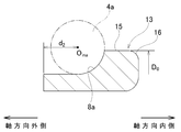
- FIG. 4 is a cross-sectional view showing an exaggerated state in which the inner ring expands as the crimped portion is formed.
- FIG. 1 is a cross-sectional view showing an example of a hub unit bearing that is the subject of the present invention.
- FIG. 2A is a cross-sectional view of an example of the hub unit bearing before the caulking portion is formed
- FIG. 2B is a cross-sectional view of an example of the hub unit bearing after the caulking portion is formed.
- FIG. 5 shows the amount of expansion of the inner ring due to external fitting into the hub ring constituting the hub in the hub of one example of the hub unit bearing, and forming a caulking portion on the hub ring. It is a graph which shows the relationship with the expansion amount of the said inner ring.
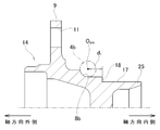
- FIG. 6 is a cross-sectional view showing the hub ring taken out.
- FIG. 7 is a cross-sectional view of an outer ring of an example of the hub unit bearing.
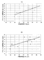
- FIG. 8A shows an expansion amount ⁇ D of the inner ring and an axial gap reduction amount ⁇ C from a single state before being fitted into the fitting cylinder portion of the hub ring in the hub of an example of the hub unit bearing.
- 8 (B) shows the expansion amount ⁇ D'of the inner ring from the state of being externally fitted to the fitting cylinder portion before forming the caulking portion, and the axial gap reduction amount ⁇ C. It is a graph which shows the relationship of.
- the hub unit bearing 1 to be the target of this example includes an outer ring 2, a hub 3, and rolling elements 4a and 4b.
- the outer ring 2 is made of a hard metal such as medium carbon steel.
- the outer ring 2 has a double-row outer ring tracks 5a and 5b on the inner peripheral surface, and has a stationary flange 6 protruding outward in the radial direction at an axial intermediate portion.
- the stationary flange 6 has support holes 7 penetrating in the axial direction at a plurality of locations in the circumferential direction in the middle portion in the radial direction.
- the outer ring 2 is supported and fixed to the suspension device by a support bolt inserted through the support hole 7 of the stationary flange 6, and does not rotate even when the wheel rotates.
- the hub 3 has double rows of inner ring tracks 8a and 8b on the outer peripheral surface, and is arranged coaxially with the outer ring 2 on the radial inside of the outer ring 2.
- the hub 3 has a rotary flange 9 protruding outward in the radial direction at a portion located outside the axial direction of the outer ring 2, and has a cylinder at the outer end in the axial direction. It has a shaped pilot unit 10.
- the rotary flange 9 has mounting holes 11 penetrating in the axial direction at a plurality of locations in the circumferential direction in the middle portion in the radial direction.
- a stud 12 is press-fitted (serration-fitted) into each of the mounting holes 11. That is, in this example, the mounting hole 11 is composed of a press-fitting hole.
- the “outside” in the axial direction means the left side of FIGS. 1 to 4, 6 and 7, which is the outside of the vehicle body when the hub unit bearing 1 is assembled to the automobile.
- the right side of FIGS. 1 to 4, 6 and 7, which is the center side of the vehicle body when the hub unit bearing 1 is assembled to the automobile is referred to as "inside" in the axial direction.
- the pilot portion 10 is inserted into a central hole that penetrates the central portion in the axial direction, and a plurality of locations in the circumferential direction of the radial intermediate portion.
- the hub nut is screwed into the tip of the stud 12 to be coupled to the rotating flange 9.
- the mounting hole of the rotary flange can also be formed by a female screw hole.
- the braking rotating body and the wheel are attached to the rotating flange by screwing the hub bolt through which the through hole provided in the braking rotating body and the through hole provided in the wheel are inserted into the mounting hole. Bond and fix.
- the hub 3 of this example includes an inner ring 13 and a hub wheel 14.
- the inner ring 13 is made of a hard metal such as bearing steel.
- the inner ring 13 has an inner ring orbit 8a on the inner side in the axial direction among the double-row inner ring orbits 8a and 8b at the axially intermediate portion of the outer peripheral surface.
- the inner ring 13 has an inner ring shoulder portion 15 on the outer peripheral surface adjacent to the inner ring orbit 8a on the inner side in the axial direction in the axial direction, and the end surface on the inner side in the axial direction and the inner ring shoulder portion 15
- the connecting portion has a chamfered portion 16 having an arcuate cross section.
- the inner ring shoulder portion 15 is formed of a cylindrical surface whose outer diameter dimension does not change in the axial direction.
- the hub wheel 14 is made of a hard metal such as medium carbon steel.
- the hub ring 14 has an inner ring raceway 8b on the outer side in the axial direction among the double-row inner ring raceways 8a and 8b at the axially intermediate portion of the outer peripheral surface.
- the hub ring 14 has a rotary flange 9 protruding outward in the radial direction at a portion located on the outer side in the axial direction with respect to the inner ring track 8b on the outer side in the axial direction, and has a cylindrical shape at an end portion on the outer side in the axial direction. It has a pilot unit 10 of the above.
- the hub ring 14 has a fitting cylinder portion 17 having a smaller outer diameter than a portion adjacent to the outer side in the axial direction and the inner ring 13 being externally fitted in a portion located inside the inner ring track 8b on the outer side in the axial direction.
- the hub ring 14 has a stepped surface 18 facing inward in the axial direction to which the end surface on the outer side in the axial direction of the inner ring 13 is abutted, and the fitting cylinder portion 17 from the inner end in the axial direction toward the outer side in the radial direction. It has a crimped portion 19 that is bent and presses the end face on the inner side in the axial direction of the inner ring 13.
- the inner ring 13 is press-fitted into the fitting cylinder portion 17 of the hub ring 14, and the crimped portion 19 presses the inner end surface of the inner ring 13 in the axial direction.
- the inner ring 13 is sandwiched between the stepped surface 18 and the crimped portion 19 from both sides in the axial direction.
- the hub 3 is configured by connecting and fixing the inner ring 13 and the hub ring 14.
- Each of the rolling elements 4a and 4b is made of a hard metal such as bearing steel or ceramics.
- a plurality of rolling elements 4a and 4b are rotatably arranged between the double-row outer ring tracks 5a and 5b and the double-row inner ring tracks 8a and 8b, respectively, while being held by the cages 20a and 20b.
- the hub 3 is rotatably supported inward in the radial direction of the outer ring 2.
- a preload is applied to the rolling elements 4a and 4b based on an axially outward force (axial force) applied from the inner ring 13.
- balls are used as rolling elements 4a and 4b, but tapered rollers can be used instead of balls.
- the pitch circle diameters of the rolling elements 4a and 4b in the inner row in the axial direction and the pitch circle diameters of the rolling elements 4a and 4b in the outer row in the axial direction are the same as each other. It can also be applied to PCD type hub unit bearings having different diameters in which the pitch circle diameter of the rolling elements in the inner row and the pitch circle diameters of the rolling elements in the outer row in the axial direction are different from each other.
- the hub unit bearing 1 exists between the inner peripheral surface of the outer ring 2 and the outer peripheral surface of the hub 3, and the rolling elements 4a and 4b are arranged on both sides of the cylindrical rolling element installation space 21 in the axial direction. Further provided with sealing devices 22a and 22b for closing the opening.
- the sealing device 22a on the inner side in the axial direction is a sealing ring having a slinger 23 that is externally fitted and fixed to the inner ring shoulder portion 15 of the inner ring 13 and a sealing lip that slides on the surface of the slinger 23 over the entire circumference. 24 and. That is, in this example, the sealing device 22a on the inner side in the axial direction is composed of a combination sealing ring.
- the axially inner sealing device that closes the axially inner opening of the rolling element installation space can also be configured by a bottomed cylindrical cover that is internally fitted and fixed to the outer ring.
- an encoder for detecting the number of rotations (rotational speed) of the wheels can be externally fitted and fixed to the shoulder portion of the inner ring of the inner ring.
- the sealing device 22b on the outer side in the axial direction has a seal lip that slides on the outer peripheral surface of the hub 3 or the inner side surface in the axial direction of the rotary flange 9 over the entire circumference. That is, in this example, the sealing device 22b on the outer side in the axial direction is composed of a sealing ring.
- the hub ring 14 is inserted into the outer ring assembly from the outside in the axial direction. Finally, the inner ring 13 is externally fitted into the fitting cylinder portion 17 of the hub ring 14 by press fitting.
- the procedure for assembling the hub unit bearing 1a is not particularly limited, and the order can be changed or the hub unit bearing 1a can be assembled at the same time as long as there is no contradiction.
- the tubular portion 25 projecting inward in the axial direction from the end face on the inner side in the axial direction of the inner ring 13 is radially outward.
- the crimped portion 19 is formed by plastically deforming the crimped portion 19.
- the inner ring 13 and the hub ring 14 are coupled and fixed to form the hub 3, and an appropriate preload is applied to the rolling elements 4a and 4b.
- the sealing device 22a on the inner side in the axial direction is mounted between the inner end portion in the axial direction of the outer ring 2 and the inner end portion in the axial direction of the hub 3, and the hub unit bearing 1 is completed.
- the method of forming the crimped portion 19 is not particularly limited.
- the caulking portion 19 presses, for example, a push die that is supported to rotate about a rotation axis inclined with respect to the central axis of the hub wheel 14 against the axially inner end of the tubular portion 25.
- the push die can be formed by rocking caulking that rotates around the central axis of the hub wheel 14.
- the caulking portion 19 can be formed by a press working (face pressing) in which the pressing die is pressed axially against the axially inner end of the tubular portion 25.
- the inner ring of the hub wheel 14 before being fitted to the fitting cylinder portion 17 of the hub wheel 14 is a single unit.
- the outer diameter dimension D 0 of 13 is measured.
- the outer diameter dimension D 0 of the inner ring shoulder portion 15 of the inner ring 13 is measured.
- the inner ring shoulder portion 15 is formed of a cylindrical surface having good shape accuracy to which the slinger 23 or the encoder of the sealing device 22a, which is a combination sealing ring, is fitted.
- the axial position of the portion of the inner ring shoulder portion 15 for measuring the outer diameter dimension D 0 is not particularly limited.
- the chamfered portion 16 It is preferable to measure the outer diameter dimension D 0 of the inner ring shoulder portion 15 in a range located outside in the axial direction and in a portion located inward in the axial direction as much as possible.
- the outer diameter dimension D 1 of the inner ring 13 is measured after the caulking portion 19 is formed and before the sealing device 22a on the inner side in the axial direction is attached.
- the axial position of the portion where the outer diameter dimension D 1 of the inner ring 13 is measured is the axial position of the portion where the outer diameter dimension D 0 of the inner ring 13 before being fitted into the fitting cylinder portion 17 of the hub ring 14 is measured. Same position.
- the axial gap reduction amount ⁇ C is obtained.
- the axial clearance reduction amount ⁇ C represents the reduction amount of the axial clearance of the hub unit bearing 1 due to the formation of the caulking portion 19.
- the relationship between the expansion amount ⁇ D of the inner ring 13 and the axial gap reduction amount ⁇ C is obtained in advance by an experiment or simulation, and is stored in the memory of the arithmetic unit as a map or an expression. That is, the expansion amount ⁇ D of the inner ring 13 is input to the arithmetic unit, and the axial gap reduction amount ⁇ C is obtained using the map or the formula.
- the preload applied to the rolling elements 4a and 4b is managed based on the axial gap reduction amount ⁇ C thus obtained. Specifically, it is determined whether or not the preload applied to the rolling elements 4a and 4b is within an appropriate range based on the axial clearance reduction amount ⁇ C, or the preload applied to the rolling elements 4a and 4b. To the proper range.
- the outer diameter dimension D 1 of the inner ring 13 in the crimped state and the inner ring 13 of a single body before being fitted into the fitting cylinder portion 17 of the hub ring 14 Based on the expansion amount ⁇ D, which is the difference from the outer diameter dimension D 0 of the hub unit bearing 1, the axial clearance reduction amount ⁇ C of the hub unit bearing 1 is obtained. That is, in this example, only the expansion amount of the inner ring 13 accompanying the formation of the crimped portion 19 (the expansion amount of the inner ring 13 between the state shown in FIG. 2A and the state shown in FIG. 2B) is sufficient.
- the inner ring 13 fitted to the fitting cylinder portion 17 of the hub ring 14 has an axially inner end surface of the inner ring 13 as an axis as shown by exaggerating with a chain line in FIG. 4 as the caulking portion 19 is formed. While shrinking the axial dimension so as to move outward in the direction, it expands outward in the radial direction.
- the fitting portion 19 is fitted regardless of the size of the tightening allowance of the inner ring 13 with respect to the fitting cylinder portion 17, as shown in FIG. It is considered that the expansion amount of the inner ring 13 from the single state before the outer fitting to the combined cylinder portion 17 becomes substantially constant, and the axial gap reduction amount ⁇ C also becomes substantially constant.
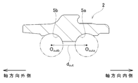
- the rolling element 4b in the outer row in the axial direction is rolled into contact with the inner ring track 8b on the outer side in the axial direction of the hub wheel 14.
- the first dimension d 1 which is the axial distance between the center O inb of the rolling element 4b and the stepped surface 18 is measured on the assumption that the rolling element 4b is moved.
- a second dimension d 2 is the axial distance between the axially outer end face of the inner ring 13 is measured.
- the first dimension d 1 and the second dimension d 2 are, for example, a curved surface portion having the same radius of curvature as 1/2 of the diameter (ball diameter) of the rolling elements 4a and 4b, and the curved surface portion that can be moved in perspective. It is possible to measure using a dedicated measuring instrument equipped with a simple stylus. That is, in the state of the hub ring 14 alone, the curved surface portion is brought into contact with the inner ring track 8b on the outer side in the axial direction, and the stylus is abutted against the stepped surface 18, so that the curvature center and the stepped surface of the curved surface portion are abutted. measuring the axial distance between 18 to obtain a first dimension d 1.
- the curved surface portion of the measuring instrument is brought into contact with the inner ring track 8a on the inner side in the axial direction, and the stylus is abutted against the end face on the outer side in the axial direction of the inner ring 13.
- the axial distance between the center of curvature of the curved surface portion and the axially outer end surface of the inner ring 13 is measured to obtain the second dimension d 2 .
- the second dimension d 2 and corrected taking into account the interference of the inner ring 13 relative to the fitting tube portion 17 to obtain a second dimension d 2 '.
- obtaining a trajectory 8a, the inner ring raceway distance d in is the distance 8b between.
- the center Oouta of the rolling elements 4a in the inner row in the axial direction measures the outer ring raceway distance d out is an axial distance between the center O outb of the rolling element 4b of the axially outer rows.
- the outer ring track spacing d out is, for example, a dedicated measuring instrument having the same radius of curvature as 1/2 of the diameter (ball diameter) of the rolling elements 4a and 4b, and having a pair of curved surfaces that can move in perspective with each other. Can be measured using. That is, in the state of the outer ring 2 alone, the pair of curved surface portions are brought into contact with the outer ring race tracks 5a and 5b of the double row, and the axial distance between the centers of curvature of the pair of curved surface portions is measured to measure the outer ring. Obtain the orbital interval d out.
- the initial axial gap C 0 in the state before the caulking portion 19 is formed is obtained.
- the center of the rolling element which is defined for measuring the first dimension, the second dimension, and the outer ring track spacing, is arbitrary on the central axis of the rolling element. Can be positioned. Specifically, for example, among the central axes of the rolling elements, the central position of the rolling elements in the axial direction can be set as the center of the rolling elements.
- the initial axial gap C 0 for obtaining the axial gap C 1 of the hub unit bearing 1b in the crimped state can be obtained by using a design value instead of obtaining by measurement.
- the preload can be set within an appropriate predetermined range.
- the combination of the outer ring 2, the inner ring 13, and the hub ring 14 for which the initial axial gap C 0 is appropriate can be selected from a plurality of outer rings 2, the inner ring 13, and the hub ring 14, or caulked. The machining load when forming the portion 19 can be adjusted.
- the relationship between the axial gap C 1 and the preload applied to the rolling elements 4a and 4b in the completed state of the hub unit bearing 1 is obtained in advance by experiments or simulations.
- a so-called third-generation hub unit bearing 1 including a hub 3 in which one inner ring 13 is coupled and fixed to the hub wheel 14 is targeted, but the present invention describes the shaft member. It is also possible to target a so-called 2.5th generation hub unit bearing having a hub formed by coupling and fixing a pair of inner rings.
- the hub ring is composed of a shaft member and an inner ring on the outer side in the axial direction of the pair of inner rings.
- the hub 3 (hub wheel 14) is solidly configured and the hub unit bearing 1 for the driven wheel is targeted has been described.
- the hub is located at the center thereof. It is also possible to target a hub unit bearing for a drive wheel, which has an engagement hole for engaging the drive shaft so as to be able to transmit torque.
- the expansion amount ⁇ D'of the inner ring 13 was set (comparative example)
- the correlation between the expansion amounts ⁇ D and ⁇ D'of the inner ring 13 and the axial gap reduction amount ⁇ C of the hub unit bearing 1 was obtained.
- the specifications of the hub unit bearing 1 were as follows.
- the caulking portion 19 has a push die supported to rotate about a rotation axis inclined with respect to the central axis of the hub wheel 14 at an axially inner end of the tubular portion 25 at 10.8 [kN]. ],
- the push die was formed by oscillating caulking to rotate (revolve) around the central axis of the hub wheel 14 at a rotational speed of 5 [s -1].
- the amount of decrease in the axial gap ⁇ C was calculated by obtaining the difference (C 0 ⁇ C 1 ) between the initial axial gap C 0 and the axial gap C 1 in the completed state.
- the outer diameter dimension D 0 of the inner ring 13 (inner ring shoulder portion 15) before being fitted into the fitting cylinder portion 17 and the inner ring 13 after forming the caulking portion 19
- the expansion amount ⁇ D of the inner ring 13 was obtained by measuring the outer diameter dimension D 1 of the above and calculating the difference (D 1 ⁇ D 0) between them.
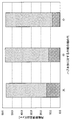
- the expansion amount ⁇ D of the inner ring 13 and the axial gap reduction amount ⁇ C obtained in this way are plotted in FIG. 8 (A). Since the calculated values of the expansion amount ⁇ D and the axial gap reduction amount ⁇ C of the inner ring 13 were the same, the number of plots in FIG. 8 (A) was 12 (as a result of overlapping some plot points). It has become.
- the inner ring expansion amount ⁇ D' was obtained by calculating the difference (D 1 ⁇ D 0 ′) of the inner ring 13 from the outer diameter dimension D 1 after forming the crimped portion 19.
- the expansion amount ⁇ D'of the inner ring 13 thus obtained and the axial gap reduction amount ⁇ C are plotted in FIG. 8 (B). Since the calculated values of the expansion amount ⁇ D'and the axial gap reduction amount ⁇ C of the inner ring 13 were the same, the number of plots in FIG. 8B was 13 (as a result of overlapping some plot points). It is an individual.
- the correlation coefficient between the expansion amount ⁇ D'of the inner ring 13 and the axial gap reduction amount ⁇ C was 0.75, whereas in the example, the expansion amount ⁇ D of the inner ring 13 and the axial gap were found to be 0.75.
- the correlation coefficient with the amount of decrease ⁇ C was calculated, it was 0.81. That is, the expansion amount ⁇ D of the inner ring 13 from the single state before being fitted to the fitting cylinder portion 17 of the hub ring 14 is from the state of being outer-fitted to the fitting cylinder portion 17 before forming the caulking portion 19. It was found that the correlation with the axial gap reduction amount ⁇ C and the preload applied to the rolling elements 4a and 4b were stronger than the expansion amount ⁇ D'of the inner ring 13.
Abstract
[Problem] To provide a method whereby pre-loading applied to a rolling element can be more precisely managed. [Solution] An inner ring (13) is fitted onto a fitting cylindrical part (17) of a hub ring (14), and the axial gap decrease ∆C of a hub unit bearing (1) is derived on the basis of the inner-ring expansion ∆D, which is the difference between the outside diameter dimension (D1) of the inner ring (13) after a crimped part (19) is formed and the outside diameter dimension (D0) of the inner ring (13) before the inner ring (13) is fitted onto the fitting cylindrical part (17).
Description
本発明は、自動車の車輪および制動用回転体を懸架装置に対して回転自在に支持するためのハブユニット軸受、および、その製造方法に関する。
The present invention relates to a hub unit bearing for rotatably supporting an automobile wheel and a rotating body for braking with respect to a suspension device, and a method for manufacturing the same.
自動車の車輪および制動用回転体は、ハブユニット軸受により懸架装置に対して回転自在に支持される。ハブユニット軸受は、内周面に複列の外輪軌道を有する外輪と、外周面に複列の内輪軌道を有するハブと、前記複列の外輪軌道と前記複列の内輪軌道との間に転動自在に配置された複数個の転動体とを備える。
The wheels of the automobile and the rotating body for braking are rotatably supported by the hub unit bearings with respect to the suspension device. The hub unit bearing rolls between an outer ring having a double-row outer ring raceway on the inner peripheral surface, a hub having a double-row inner ring raceway on the outer peripheral surface, and the double-row outer ring raceway and the double-row inner ring raceway. It is provided with a plurality of rolling elements arranged so as to be movable.
前記ハブは、内輪とハブ輪とを備える。前記内輪は、軸方向外側の端面を、前記ハブ輪の軸方向中間部に備えられ、軸方向内側を向いた段差面に突き当てた状態で、前記ハブ輪の軸方向内側部分に備えられた嵌合筒部に、圧入により外嵌されている。この状態で、前記嵌合筒部のうちで前記内輪の軸方向内側の端面よりも軸方向内側に突出した筒状部を、径方向外側に向けて塑性変形させることで形成したかしめ部により、前記内輪の軸方向内側の端面を押え付けている。これにより、前記内輪と前記ハブ輪とを結合固定し、かつ、前記転動体に予圧を付与している。
The hub includes an inner ring and a hub ring. The inner ring is provided on the axially inner portion of the hub wheel in a state where the axially outer end surface is provided on the axially intermediate portion of the hub ring and is abutted against the stepped surface facing the axially inward side. It is externally fitted to the fitting cylinder by press fitting. In this state, the caulking portion formed by plastically deforming the tubular portion of the fitting tubular portion that protrudes inward in the axial direction from the axially inner end surface of the inner ring is formed by plastically deforming the inner ring in the radial direction. The end face on the inner side in the axial direction of the inner ring is pressed. As a result, the inner ring and the hub ring are coupled and fixed, and a preload is applied to the rolling element.
ハブユニット軸受では、転動体に付与した予圧が適正範囲に収まっていないと、予圧が大きすぎる場合には、ハブユニット軸受の寿命が短くなったり、ハブユニット軸受の動トルク(回転抵抗)が増大して自動車の走行性能が低下したりし、反対に、予圧が小さすぎる場合には、モーメント剛性が不足し、車両の操安性が悪化するなどの不具合を招く。このため、転動体に付与する予圧に関しては、厳しい管理が要求される。
In the hub unit bearing, if the preload applied to the rolling element is not within the appropriate range, the life of the hub unit bearing will be shortened or the dynamic torque (rotational resistance) of the hub unit bearing will increase if the preload is too large. As a result, the running performance of the vehicle deteriorates, and conversely, if the preload is too small, the moment rigidity becomes insufficient and the maneuverability of the vehicle deteriorates. Therefore, strict control is required for the preload applied to the rolling element.
特開2003-13979号公報には、ハブ輪に内輪を外嵌した後、かしめ部を形成する前後の内輪の外径寸法を測定することで、該内輪の外径寸法の膨張量に基づいて、かしめ部から内輪に加わる軸力を管理する方法が記載されている。特開2003-13979号公報に記載の方法によれば、かしめ部の軸力が不足して、ハブ輪と内輪との間でクリープが発生したり、かしめ部の軸力が過大になって、内輪軌道に圧痕が形成されたりすることを防止できる。
According to Japanese Patent Application Laid-Open No. 2003-13979, after the inner ring is fitted onto the hub ring, the outer diameter of the inner ring before and after forming the crimped portion is measured, and based on the expansion amount of the outer diameter of the inner ring. , A method of managing the axial force applied to the inner ring from the crimped portion is described. According to the method described in Japanese Patent Application Laid-Open No. 2003-13979, the axial force of the crimped portion is insufficient, creep occurs between the hub ring and the inner ring, or the axial force of the crimped portion becomes excessive. It is possible to prevent the formation of indentations on the inner ring track.
ところで、内輪の外周面に備えられた軸方向内側の内輪軌道は、軸方向内側に向かうほど径方向外側に向かう方向に傾斜している。したがって、内輪をハブ輪に、圧入により外嵌することに伴って、内輪が膨張する(内輪の外径寸法が増大する)と、軸方向内側列の転動体が、内輪軌道により軸方向外側に向けて押圧され、転動体に付与される予圧が増大する。すなわち、転動体に付与される予圧には、かしめ部の形成に伴う内輪の膨張量だけでなく、内輪のハブ輪への圧入に伴う膨張量も影響すると考えられる。内輪のハブ輪への圧入に伴う膨張量は、嵌合筒部の外周面に対する内輪の内周面の締め代に基づいて変化する。特開2003-13979号公報に記載の方法は、ハブ輪への内輪の圧入に伴う膨張量が、転動体に付与される予圧に与える影響が考慮されておらず、前記予圧をより正確に管理する面からは、さらなる改良の余地があるといえる。
By the way, the inner ring orbit on the inner side of the inner ring provided on the outer peripheral surface of the inner ring is inclined toward the outer side in the radial direction toward the inner side in the axial direction. Therefore, when the inner ring expands (the outer diameter dimension of the inner ring increases) as the inner ring is fitted into the hub ring by press fitting, the rolling elements in the inner row in the axial direction move outward in the axial direction due to the inner ring trajectory. The preload applied to the rolling element is increased by being pressed toward the rolling element. That is, it is considered that the preload applied to the rolling element is affected not only by the amount of expansion of the inner ring due to the formation of the crimped portion but also by the amount of expansion due to the press fitting of the inner ring into the hub ring. The amount of expansion of the inner ring due to press-fitting into the hub ring changes based on the tightening allowance of the inner peripheral surface of the inner ring with respect to the outer peripheral surface of the fitting cylinder portion. The method described in Japanese Patent Application Laid-Open No. 2003-13979 does not consider the influence of the amount of expansion due to the press-fitting of the inner ring into the hub ring on the preload applied to the rolling element, and manages the preload more accurately. From the aspect of doing so, it can be said that there is room for further improvement.
本発明は、上述のような事情を鑑みて、転動体に付与される予圧を、より正確に管理することができる、ハブユニット軸受、および、その製造方法を実現することを目的としている。
In view of the above circumstances, an object of the present invention is to realize a hub unit bearing capable of more accurately controlling the preload applied to the rolling element, and a method for manufacturing the hub unit bearing.
本発明の対象となるハブユニット軸受は、外輪と、ハブと、複数個の転動体とを備える。
The hub unit bearing which is the object of the present invention includes an outer ring, a hub, and a plurality of rolling elements.
前記外輪は、内周面に複列の外輪軌道を有し、懸架装置に支持固定されて回転しない。
The outer ring has a double-row outer ring track on the inner peripheral surface, is supported and fixed to the suspension device, and does not rotate.
前記ハブは、外周面に複列の内輪軌道を有し、車輪が固定されて該車輪とともに回転する。
The hub has a double-row inner ring track on the outer peripheral surface, and the wheels are fixed and rotate together with the wheels.
前記複数個の転動体は、前記複列の外輪軌道と前記複列の内輪軌道との間に転動自在に配置され、かつ、予圧が付与されている。
The plurality of rolling elements are rotatably arranged between the outer ring track of the double row and the inner ring track of the double row, and a preload is applied.
前記ハブは、外周面に、前記複列の内輪軌道のうちの軸方向内側の内輪軌道を有する内輪と、軸方向中間部外周面に、前記複列の内輪軌道のうちの軸方向外側の内輪軌道を有するハブ輪とを備える。
The hub has an inner ring having an inner ring track on the outer peripheral surface in the axial direction of the inner ring track of the double row, and an inner ring on the outer peripheral surface of the intermediate portion in the axial direction on the outer ring in the axial direction of the inner ring track of the double row. It is equipped with a hub wheel having a track.
前記内輪は、前記ハブ輪のうちで前記軸方向外側の内輪軌道よりも軸方向内側に位置する嵌合筒部に外嵌され、前記ハブ輪は、前記嵌合筒部の軸方向内側の端部から径方向外側に向けて折れ曲がり、前記内輪の軸方向内側の端面を押え付けるかしめ部を有する。すなわち、前記内輪と前記ハブ輪とは、前記ハブ輪のうちで前記軸方向外側の内輪軌道よりも軸方向内側に位置する嵌合筒部に前記内輪を外嵌した状態で、前記ハブ輪のうちで前記内輪の軸方向内側の端面よりも軸方向内側に突出した筒状部を、径方向外方に塑性変形させて形成したかしめ部により、前記内輪の軸方向内側の端面を押え付けることで結合固定される。
The inner ring is fitted onto a fitting cylinder portion of the hub ring located axially inside the inner ring track on the outer side in the axial direction, and the hub ring is an axially inner end of the fitting cylinder portion. It has a caulking portion that bends outward in the radial direction from the portion and presses the end face on the inner side in the axial direction of the inner ring. That is, the inner ring and the hub ring are the hub wheels in a state in which the inner ring is outerly fitted to a fitting cylinder portion located axially inside the inner ring track on the outer side in the axial direction. The inner end face of the inner ring is pressed by a caulking portion formed by plastically deforming a tubular portion protruding inward in the axial direction from the inner end surface of the inner ring in the axial direction. It is bonded and fixed with.
本発明の一実施形態のハブユニット軸受の製造方法は、
前記内輪を前記嵌合筒部に外嵌する前に、前記内輪の外径寸法を測定する、嵌合前工程と、
前記ハブ輪の周囲に、前記外輪と前記転動体とを配置する、配置工程と、
前記嵌合筒部に前記内輪を外嵌する、外嵌工程と、
前記筒状部を径方向外方に塑性変形させて前記かしめ部を形成する、かしめ工程と、
前記かしめ部を形成した後で、前記内輪の外径寸法を測定する、かしめ後工程と、
を備え、
前記かしめ部を形成した後の前記内輪の外径寸法と、前記嵌合筒部に外嵌する前の前記内輪の外径寸法との差である内輪膨張量に基づいて、前記外嵌工程と前記かしめ工程とにより減少したアキシアル隙間減少量を求め、
前記アキシアル隙間減少量に基づいて、前記予圧を管理する。 The method for manufacturing a hub unit bearing according to an embodiment of the present invention is as follows.
A pre-fitting step of measuring the outer diameter of the inner ring before fitting the inner ring to the fitting cylinder portion.
An arrangement step of arranging the outer ring and the rolling element around the hub ring, and
An outer fitting step of outerly fitting the inner ring to the fitting cylinder portion,
A crimping step in which the tubular portion is plastically deformed outward in the radial direction to form the caulking portion.
After the caulking portion is formed, the outer diameter dimension of the inner ring is measured, and the post-caulking step is performed.
With
Based on the inner ring expansion amount, which is the difference between the outer diameter dimension of the inner ring after forming the crimped portion and the outer diameter dimension of the inner ring before outer fitting to the fitting cylinder portion, the outer fitting step The amount of reduction in the axial gap reduced by the caulking step was determined.
The preload is controlled based on the amount of reduction in the axial gap.
なお、前記配置工程と前記外嵌工程とは、同時に実施することもできる。
The arrangement process and the outer fitting process can be performed at the same time.
本発明の一実施形態のハブユニット軸受の製造方法において、前記かしめ部を形成する以前の状態の前記ハブユニット軸受のアキシアル隙間である初期アキシアル隙間から前記アキシアル隙間減少量を減じて、前記かしめ部を形成した後の状態での前記ハブユニット軸受のアキシアル隙間を算出し、該アキシアル隙間に基づいて、前記ハブユニット軸受の完成状態での前記予圧を求めることができる。
In the method for manufacturing a hub unit bearing according to an embodiment of the present invention, the amount of reduction in the axial gap is subtracted from the initial axial gap which is the axial gap of the hub unit bearing in the state before the caulking portion is formed, and the caulking portion is formed. The axial gap of the hub unit bearing in the state after forming the above can be calculated, and the preload in the completed state of the hub unit bearing can be obtained based on the axial gap.
前記アキシアル隙間に基づいて求められた前記ハブユニット軸受の完成状態での前記予圧をフィードバックして、前記予圧を所定範囲に設定することができる。
The preload in the completed state of the hub unit bearing obtained based on the axial gap can be fed back to set the preload within a predetermined range.
本発明の一実施形態のハブユニット軸受は、前記かしめ部を形成した後で測定した前記内輪の外径寸法と、前記内輪を前記嵌合筒部に外嵌する前に測定した前記内輪の外径寸法との差である内輪膨張量から求めたアキシアル隙間減少量に基づいて、前記予圧が管理されている。
The hub unit bearing according to the embodiment of the present invention has the outer diameter dimension of the inner ring measured after forming the crimped portion and the outer diameter of the inner ring measured before the inner ring is fitted into the fitting cylinder portion. The preload is controlled based on the amount of decrease in the axial gap obtained from the amount of expansion of the inner ring, which is the difference from the diameter dimension.
本発明の一実施形態によれば、転動体に付与される予圧を、より正確に管理することができる。
According to one embodiment of the present invention, the preload applied to the rolling element can be managed more accurately.
本発明の実施の形態の1例について、図1~図7を用いて説明する。
An example of the embodiment of the present invention will be described with reference to FIGS. 1 to 7.
<ハブユニット軸受の構造>
本例の対象となるハブユニット軸受1は、外輪2と、ハブ3と、転動体4a、4bとを備える。 <Hub unit bearing structure>
The hub unit bearing 1 to be the target of this example includes anouter ring 2, a hub 3, and rolling elements 4a and 4b.
本例の対象となるハブユニット軸受1は、外輪2と、ハブ3と、転動体4a、4bとを備える。 <Hub unit bearing structure>
The hub unit bearing 1 to be the target of this example includes an
外輪2は、中炭素鋼などの硬質金属により構成されている。外輪2は、内周面に、複列の外輪軌道5a、5bを有し、かつ、軸方向中間部に、径方向外側に向けて突出した静止フランジ6を有する。静止フランジ6は、径方向中間部の円周方向複数箇所に、軸方向に貫通する支持孔7を有する。外輪2は、静止フランジ6の支持孔7を挿通した支持ボルトにより、懸架装置に対し支持固定され、車輪が回転する際にも回転しない。
The outer ring 2 is made of a hard metal such as medium carbon steel. The outer ring 2 has a double-row outer ring tracks 5a and 5b on the inner peripheral surface, and has a stationary flange 6 protruding outward in the radial direction at an axial intermediate portion. The stationary flange 6 has support holes 7 penetrating in the axial direction at a plurality of locations in the circumferential direction in the middle portion in the radial direction. The outer ring 2 is supported and fixed to the suspension device by a support bolt inserted through the support hole 7 of the stationary flange 6, and does not rotate even when the wheel rotates.
ハブ3は、外周面に、複列の内輪軌道8a、8bを有し、かつ、外輪2の径方向内側に外輪2と同軸に配置される。ハブ3は、外輪2の軸方向外側の端部よりも軸方向外側に位置する部分に、径方向外側に向けて突出した回転フランジ9を有し、かつ、軸方向外側の端部に、円筒状のパイロット部10を有する。回転フランジ9は、径方向中間部の円周方向複数箇所に、軸方向に貫通する取付孔11を有する。取付孔11のそれぞれには、スタッド12が圧入(セレーション嵌合)されている。すなわち、本例では、取付孔11は、圧入孔により構成される。
The hub 3 has double rows of inner ring tracks 8a and 8b on the outer peripheral surface, and is arranged coaxially with the outer ring 2 on the radial inside of the outer ring 2. The hub 3 has a rotary flange 9 protruding outward in the radial direction at a portion located outside the axial direction of the outer ring 2, and has a cylinder at the outer end in the axial direction. It has a shaped pilot unit 10. The rotary flange 9 has mounting holes 11 penetrating in the axial direction at a plurality of locations in the circumferential direction in the middle portion in the radial direction. A stud 12 is press-fitted (serration-fitted) into each of the mounting holes 11. That is, in this example, the mounting hole 11 is composed of a press-fitting hole.
なお、軸方向に関して「外」とは、ハブユニット軸受1を自動車に組み付けた状態で車体の外側となる、図1~図4、図6および図7の左側をいう。反対に、ハブユニット軸受1を自動車に組み付けた状態で車体の中央側となる、図1~図4、図6および図7の右側を、軸方向に関して「内」という。
The "outside" in the axial direction means the left side of FIGS. 1 to 4, 6 and 7, which is the outside of the vehicle body when the hub unit bearing 1 is assembled to the automobile. On the contrary, the right side of FIGS. 1 to 4, 6 and 7, which is the center side of the vehicle body when the hub unit bearing 1 is assembled to the automobile, is referred to as "inside" in the axial direction.
ディスクやドラムなどの制動用回転体、及び、車輪を構成するホイールは、中心部を軸方向に貫通する中心孔に、パイロット部10を挿通し、かつ、径方向中間部の円周方向複数箇所を軸方向に貫通する通孔に、スタッド12を挿通した状態で、スタッド12の先端部にハブナットを螺合することにより、回転フランジ9に結合される。
For braking rotating bodies such as discs and drums, and wheels constituting the wheels, the pilot portion 10 is inserted into a central hole that penetrates the central portion in the axial direction, and a plurality of locations in the circumferential direction of the radial intermediate portion. With the stud 12 inserted in the through hole penetrating in the axial direction, the hub nut is screwed into the tip of the stud 12 to be coupled to the rotating flange 9.
なお、回転フランジの取付孔を、雌ねじ孔により構成することもできる。この場合には、制動用回転体に備えられた通孔と、ホイールに備えられた通孔とを挿通したハブボルトを、取付孔に螺合することにより、制動用回転体および車輪を回転フランジに結合固定する。
The mounting hole of the rotary flange can also be formed by a female screw hole. In this case, the braking rotating body and the wheel are attached to the rotating flange by screwing the hub bolt through which the through hole provided in the braking rotating body and the through hole provided in the wheel are inserted into the mounting hole. Bond and fix.
本例のハブ3は、内輪13とハブ輪14とを備える。
The hub 3 of this example includes an inner ring 13 and a hub wheel 14.
内輪13は、軸受鋼などの硬質金属により構成されている。内輪13は、外周面のうちの軸方向中間部に、複列の内輪軌道8a、8bのうちの軸方向内側の内輪軌道8aを有する。さらに、内輪13は、外周面のうち、軸方向内側の内輪軌道8aの軸方向内側に隣接する部分に、内輪肩部15を有し、かつ、軸方向内側の端面と内輪肩部15との接続部に、断面円弧形の面取り部16を有する。内輪肩部15は、軸方向にわたり外径寸法が変化しない円筒面により構成される。
The inner ring 13 is made of a hard metal such as bearing steel. The inner ring 13 has an inner ring orbit 8a on the inner side in the axial direction among the double-row inner ring orbits 8a and 8b at the axially intermediate portion of the outer peripheral surface. Further, the inner ring 13 has an inner ring shoulder portion 15 on the outer peripheral surface adjacent to the inner ring orbit 8a on the inner side in the axial direction in the axial direction, and the end surface on the inner side in the axial direction and the inner ring shoulder portion 15 The connecting portion has a chamfered portion 16 having an arcuate cross section. The inner ring shoulder portion 15 is formed of a cylindrical surface whose outer diameter dimension does not change in the axial direction.
ハブ輪14は、中炭素鋼などの硬質金属により構成されている。ハブ輪14は、外周面の軸方向中間部に、複列の内輪軌道8a、8bのうちの軸方向外側の内輪軌道8bを有する。ハブ輪14は、軸方向外側の内輪軌道8bよりも軸方向外側に位置する部分に、径方向外側に向けて突出した回転フランジ9を有し、かつ、軸方向外側の端部に、円筒状のパイロット部10を有する。
The hub wheel 14 is made of a hard metal such as medium carbon steel. The hub ring 14 has an inner ring raceway 8b on the outer side in the axial direction among the double-row inner ring raceways 8a and 8b at the axially intermediate portion of the outer peripheral surface. The hub ring 14 has a rotary flange 9 protruding outward in the radial direction at a portion located on the outer side in the axial direction with respect to the inner ring track 8b on the outer side in the axial direction, and has a cylindrical shape at an end portion on the outer side in the axial direction. It has a pilot unit 10 of the above.
ハブ輪14は、軸方向外側の内輪軌道8bよりも軸方向内側に位置する部分に、軸方向外側に隣接する部分よりも外径が小さく、内輪13が外嵌される嵌合筒部17を有する。さらに、ハブ輪14は、内輪13の軸方向外側の端面が突き当てられる、軸方向内側を向いた段差面18と、嵌合筒部17の軸方向内側の端部から径方向外側に向けて折れ曲がり、内輪13の軸方向内側の端面を押え付けるかしめ部19とを有する。すなわち、本例のハブ3は、ハブ輪14の嵌合筒部17に内輪13を圧入により外嵌し、かつ、かしめ部19により内輪13の軸方向内側の端面を押え付けている。換言すれば、段差面18とかしめ部19との間で内輪13を軸方向両側から挟持している。これにより、内輪13とハブ輪14とを結合固定することで、ハブ3を構成している。
The hub ring 14 has a fitting cylinder portion 17 having a smaller outer diameter than a portion adjacent to the outer side in the axial direction and the inner ring 13 being externally fitted in a portion located inside the inner ring track 8b on the outer side in the axial direction. Have. Further, the hub ring 14 has a stepped surface 18 facing inward in the axial direction to which the end surface on the outer side in the axial direction of the inner ring 13 is abutted, and the fitting cylinder portion 17 from the inner end in the axial direction toward the outer side in the radial direction. It has a crimped portion 19 that is bent and presses the end face on the inner side in the axial direction of the inner ring 13. That is, in the hub 3 of this example, the inner ring 13 is press-fitted into the fitting cylinder portion 17 of the hub ring 14, and the crimped portion 19 presses the inner end surface of the inner ring 13 in the axial direction. In other words, the inner ring 13 is sandwiched between the stepped surface 18 and the crimped portion 19 from both sides in the axial direction. As a result, the hub 3 is configured by connecting and fixing the inner ring 13 and the hub ring 14.
転動体4a、4bのそれぞれは、軸受鋼などの硬質金属、または、セラミックスにより構成される。転動体4a、4bは、複列の外輪軌道5a、5bと複列の内輪軌道8a、8bとの間に、それぞれ複数個ずつ、保持器20a、20bにより保持された状態で転動自在に配置されている。これにより、ハブ3は、外輪2の径方向内側に回転自在に支持される。また、転動体4a、4bには、内輪13から加わる軸方向外側を向いた力(軸力)に基づいて、予圧が付与されている。
Each of the rolling elements 4a and 4b is made of a hard metal such as bearing steel or ceramics. A plurality of rolling elements 4a and 4b are rotatably arranged between the double-row outer ring tracks 5a and 5b and the double-row inner ring tracks 8a and 8b, respectively, while being held by the cages 20a and 20b. Has been done. As a result, the hub 3 is rotatably supported inward in the radial direction of the outer ring 2. Further, a preload is applied to the rolling elements 4a and 4b based on an axially outward force (axial force) applied from the inner ring 13.
本例では、転動体4a、4bとして玉を使用しているが、玉に代えて円すいころを使用することもできる。また、本例では、軸方向内側列の転動体4a、4bのピッチ円直径と、軸方向外側列の転動体4a、4bのピッチ円直径とを互いに同じとしているが、本発明は、軸方向内側列の転動体のピッチ円直径と、軸方向外側列の転動体のピッチ円直径とが互いに異なる異径PCD型のハブユニット軸受に適用することもできる。
In this example, balls are used as rolling elements 4a and 4b, but tapered rollers can be used instead of balls. Further, in this example, the pitch circle diameters of the rolling elements 4a and 4b in the inner row in the axial direction and the pitch circle diameters of the rolling elements 4a and 4b in the outer row in the axial direction are the same as each other. It can also be applied to PCD type hub unit bearings having different diameters in which the pitch circle diameter of the rolling elements in the inner row and the pitch circle diameters of the rolling elements in the outer row in the axial direction are different from each other.
ハブユニット軸受1は、外輪2の内周面とハブ3の外周面との間に存在し、かつ、転動体4a、4bが配置された、円筒状の転動体設置空間21の軸方向両側の開口部を塞ぐ、シール装置22a、22bをさらに備える。
The hub unit bearing 1 exists between the inner peripheral surface of the outer ring 2 and the outer peripheral surface of the hub 3, and the rolling elements 4a and 4b are arranged on both sides of the cylindrical rolling element installation space 21 in the axial direction. Further provided with sealing devices 22a and 22b for closing the opening.
シール装置22a、22bのうち、軸方向内側のシール装置22aは、内輪13の内輪肩部15に外嵌固定されるスリンガ23と、スリンガ23の表面に全周にわたり摺接するシールリップを有するシールリング24とを備える。すなわち、本例では、軸方向内側のシール装置22aは、組み合わせシールリングにより構成される。
Of the sealing devices 22a and 22b, the sealing device 22a on the inner side in the axial direction is a sealing ring having a slinger 23 that is externally fitted and fixed to the inner ring shoulder portion 15 of the inner ring 13 and a sealing lip that slides on the surface of the slinger 23 over the entire circumference. 24 and. That is, in this example, the sealing device 22a on the inner side in the axial direction is composed of a combination sealing ring.
なお、転動体設置空間の軸方向内側の開口部を塞ぐ、軸方向内側のシール装置を、外輪に内嵌固定された有底円筒状のカバーにより構成することもできる。この場合、必要に応じて、内輪の内輪肩部に、車輪の回転数(回転速度)を検出するためのエンコーダを外嵌固定することができる。
It should be noted that the axially inner sealing device that closes the axially inner opening of the rolling element installation space can also be configured by a bottomed cylindrical cover that is internally fitted and fixed to the outer ring. In this case, if necessary, an encoder for detecting the number of rotations (rotational speed) of the wheels can be externally fitted and fixed to the shoulder portion of the inner ring of the inner ring.
シール装置22a、22bのうち、軸方向外側のシール装置22bは、ハブ3の外周面または回転フランジ9の軸方向内側面に全周にわたり摺接するシールリップを有する。すなわち、本例では、軸方向外側のシール装置22bは、シールリングにより構成される。
Of the sealing devices 22a and 22b, the sealing device 22b on the outer side in the axial direction has a seal lip that slides on the outer peripheral surface of the hub 3 or the inner side surface in the axial direction of the rotary flange 9 over the entire circumference. That is, in this example, the sealing device 22b on the outer side in the axial direction is composed of a sealing ring.
<ハブユニット軸受の製造方法>
ハブユニット軸受1を製造する際には、図2(A)に示すように、ハブ輪14の周囲に、外輪2と転動体4a、4bとを配置し、かつ、嵌合筒部17に内輪13を外嵌して、かしめ部19を形成する以前の状態のハブユニット軸受1aを組み立てる。具体的には、例えば、転動体4a、4bを保持器20a、20bに保持した状態で、外輪2の複列の外輪軌道5a、5bの径方向内側に配置し、かつ、外輪2の軸方向外側の端部に、軸方向外側のシール装置22bを内嵌して外輪組立体を得る。次いで、前記外輪組立体に、ハブ輪14を軸方向外側から挿入する。最後に、内輪13を、ハブ輪14の嵌合筒部17に圧入により外嵌する。ただし、ハブユニット軸受1aを組み立てる手順については、特に限定されず、矛盾を生じない限り、順番を入れ替えたり、同時に実施したりすることができる。 <Manufacturing method of hub unit bearing>
When manufacturing the hub unit bearing 1, as shown in FIG. 2A, theouter ring 2 and the rolling elements 4a and 4b are arranged around the hub ring 14, and the inner ring is formed on the fitting cylinder portion 17. 13 is fitted externally to assemble the hub unit bearing 1a in the state before forming the crimped portion 19. Specifically, for example, in a state where the rolling elements 4a and 4b are held by the cages 20a and 20b, they are arranged inside the outer ring orbits 5a and 5b of the double row of the outer ring 2 in the radial direction and in the axial direction of the outer ring 2. An axially outer sealing device 22b is internally fitted to the outer end to obtain an outer ring assembly. Next, the hub ring 14 is inserted into the outer ring assembly from the outside in the axial direction. Finally, the inner ring 13 is externally fitted into the fitting cylinder portion 17 of the hub ring 14 by press fitting. However, the procedure for assembling the hub unit bearing 1a is not particularly limited, and the order can be changed or the hub unit bearing 1a can be assembled at the same time as long as there is no contradiction.
ハブユニット軸受1を製造する際には、図2(A)に示すように、ハブ輪14の周囲に、外輪2と転動体4a、4bとを配置し、かつ、嵌合筒部17に内輪13を外嵌して、かしめ部19を形成する以前の状態のハブユニット軸受1aを組み立てる。具体的には、例えば、転動体4a、4bを保持器20a、20bに保持した状態で、外輪2の複列の外輪軌道5a、5bの径方向内側に配置し、かつ、外輪2の軸方向外側の端部に、軸方向外側のシール装置22bを内嵌して外輪組立体を得る。次いで、前記外輪組立体に、ハブ輪14を軸方向外側から挿入する。最後に、内輪13を、ハブ輪14の嵌合筒部17に圧入により外嵌する。ただし、ハブユニット軸受1aを組み立てる手順については、特に限定されず、矛盾を生じない限り、順番を入れ替えたり、同時に実施したりすることができる。 <Manufacturing method of hub unit bearing>
When manufacturing the hub unit bearing 1, as shown in FIG. 2A, the
次いで、図2(A)から図2(B)に示すように、ハブ輪14のうち、内輪13の軸方向内側の端面よりも軸方向内側に突出した筒状部25を、径方向外側に向けて塑性変形させることでかしめ部19を形成する。これにより、内輪13とハブ輪14とを結合固定してハブ3を構成し、かつ、転動体4a、4bに適正な予圧を付与する。そして、外輪2の軸方向内側の端部とハブ3の軸方向内側の端部との間に、軸方向内側のシール装置22aを装着し、ハブユニット軸受1として完成する。
Next, as shown in FIGS. 2 (A) to 2 (B), of the hub ring 14, the tubular portion 25 projecting inward in the axial direction from the end face on the inner side in the axial direction of the inner ring 13 is radially outward. The crimped portion 19 is formed by plastically deforming the crimped portion 19. As a result, the inner ring 13 and the hub ring 14 are coupled and fixed to form the hub 3, and an appropriate preload is applied to the rolling elements 4a and 4b. Then, the sealing device 22a on the inner side in the axial direction is mounted between the inner end portion in the axial direction of the outer ring 2 and the inner end portion in the axial direction of the hub 3, and the hub unit bearing 1 is completed.
かしめ部19を形成する方法については、特に限定されない。かしめ部19は、例えば、ハブ輪14の中心軸に対して傾斜した自転軸を中心とする回転を可能に支持された押し型を、筒状部25の軸方向内側の端部に押し付けつつ、前記押し型を、ハブ輪14の中心軸の周りで回転運動させる揺動かしめにより形成することができる。あるいは、かしめ部19は、押し型を、筒状部25の軸方向内側の端部に軸方向に押し付けるプレス加工(面押し加工)により形成することもできる。
The method of forming the crimped portion 19 is not particularly limited. The caulking portion 19 presses, for example, a push die that is supported to rotate about a rotation axis inclined with respect to the central axis of the hub wheel 14 against the axially inner end of the tubular portion 25. The push die can be formed by rocking caulking that rotates around the central axis of the hub wheel 14. Alternatively, the caulking portion 19 can be formed by a press working (face pressing) in which the pressing die is pressed axially against the axially inner end of the tubular portion 25.
本例の製造方法では、ハブユニット軸受1の完成状態で転動体4a、4bに付与された予圧を管理するために、ハブ輪14の嵌合筒部17に外嵌する以前の単体での内輪13の外径寸法D0を測定しておく。具体的には、内輪13の内輪肩部15の外径寸法D0を測定する。内輪肩部15は、組み合わせシールリングであるシール装置22aのスリンガ23またはエンコーダが外嵌される、形状精度が良好な円筒面により構成される。内輪肩部15のうちで外径寸法D0を測定する部分の軸方向位置については、特に限定されない。ただし、ハブ輪14に外嵌する前の内輪13の外径寸法D0と、かしめ部19の形成後の内輪13の外径寸法D1との差を大きく確保する面からは、面取り部16よりも軸方向外側に位置する範囲で、かつ、できる限り軸方向内側に位置する部分で、内輪肩部15の外径寸法D0を測定することが好ましい。
In the manufacturing method of this example, in order to manage the preload applied to the rolling elements 4a and 4b in the completed state of the hub unit bearing 1, the inner ring of the hub wheel 14 before being fitted to the fitting cylinder portion 17 of the hub wheel 14 is a single unit. The outer diameter dimension D 0 of 13 is measured. Specifically, the outer diameter dimension D 0 of the inner ring shoulder portion 15 of the inner ring 13 is measured. The inner ring shoulder portion 15 is formed of a cylindrical surface having good shape accuracy to which the slinger 23 or the encoder of the sealing device 22a, which is a combination sealing ring, is fitted. The axial position of the portion of the inner ring shoulder portion 15 for measuring the outer diameter dimension D 0 is not particularly limited. However, from the viewpoint of ensuring a large difference between the outer diameter dimension D 0 of the inner ring 13 before being fitted onto the hub ring 14 and the outer diameter dimension D 1 of the inner ring 13 after the caulking portion 19 is formed, the chamfered portion 16 It is preferable to measure the outer diameter dimension D 0 of the inner ring shoulder portion 15 in a range located outside in the axial direction and in a portion located inward in the axial direction as much as possible.
本例の製造方法では、かしめ部19を形成した後、軸方向内側のシール装置22aを装着する以前に、内輪13の外径寸法D1を測定する。内輪13の外径寸法D1を測定する部分の軸方向位置は、ハブ輪14の嵌合筒部17に外嵌する以前の内輪13の外径寸法D0を測定した部分の軸方向位置と同じ位置とする。
In the manufacturing method of this example, the outer diameter dimension D 1 of the inner ring 13 is measured after the caulking portion 19 is formed and before the sealing device 22a on the inner side in the axial direction is attached. The axial position of the portion where the outer diameter dimension D 1 of the inner ring 13 is measured is the axial position of the portion where the outer diameter dimension D 0 of the inner ring 13 before being fitted into the fitting cylinder portion 17 of the hub ring 14 is measured. Same position.
かしめ部19を形成した後(かしめ完了状態)の内輪13の外径寸法D1と、ハブ輪14の嵌合筒部17に外嵌する以前の内輪13の外径寸法D0との差(D1-D0)である内輪13の膨張量ΔDに基づいて、アキシアル隙間減少量ΔCを求める。アキシアル隙間減少量ΔCは、かしめ部19を形成することに伴う、ハブユニット軸受1のアキシアル隙間の減少量を表す。内輪13の膨張量ΔDと、アキシアル隙間減少量ΔCとの関係は、予め実験やシミュレーションなどによって求め、演算装置のメモリに、マップまたは式として記憶しておく。すなわち、内輪13の膨張量ΔDを前記演算装置に入力し、前記マップまたは式を用いて、アキシアル隙間減少量ΔCを求める。
The difference between the outer diameter dimension D 1 of the inner ring 13 after the caulking portion 19 is formed (in the crimping completed state) and the outer diameter dimension D 0 of the inner ring 13 before being fitted into the fitting cylinder portion 17 of the hub ring 14 ( Based on the expansion amount ΔD of the inner ring 13 which is D 1 −D 0), the axial gap reduction amount ΔC is obtained. The axial clearance reduction amount ΔC represents the reduction amount of the axial clearance of the hub unit bearing 1 due to the formation of the caulking portion 19. The relationship between the expansion amount ΔD of the inner ring 13 and the axial gap reduction amount ΔC is obtained in advance by an experiment or simulation, and is stored in the memory of the arithmetic unit as a map or an expression. That is, the expansion amount ΔD of the inner ring 13 is input to the arithmetic unit, and the axial gap reduction amount ΔC is obtained using the map or the formula.
本例では、このようにして求めたアキシアル隙間減少量ΔCに基づいて、転動体4a、4bに付与される予圧を管理している。具体的には、アキシアル隙間減少量ΔCに基づいて、転動体4a、4bに付与される予圧が適正範囲に収まっているか否かを判断するか、あるいは、転動体4a、4bに付与される予圧を適正範囲に設定する。
In this example, the preload applied to the rolling elements 4a and 4b is managed based on the axial gap reduction amount ΔC thus obtained. Specifically, it is determined whether or not the preload applied to the rolling elements 4a and 4b is within an appropriate range based on the axial clearance reduction amount ΔC, or the preload applied to the rolling elements 4a and 4b. To the proper range.
上述のように、本例のハブユニット軸受の製造方法では、かしめ完了状態における内輪13の外径寸法D1と、ハブ輪14の嵌合筒部17に外嵌する以前の単体での内輪13の外径寸法D0との差である膨張量ΔDに基づいて、ハブユニット軸受1のアキシアル隙間減少量ΔCを求めている。すなわち、本例では、かしめ部19を形成することに伴う内輪13の膨張量(図2(A)に示す状態から図2(B)に示す状態までの間の内輪13の膨張量)だけでなく、ハブ輪14の嵌合筒部17に圧入することに伴う内輪13の膨張量が、かしめ部19を形成することによるハブユニット軸受1のアキシアル隙間の減少量に与える影響を考慮している。したがって、本例によれば、特開2003-13979に記載の方法のように、かしめ部の形成に伴う内輪の膨張量のみを考慮し、ハブ輪に圧入することに伴う内輪の膨張量を考慮していない場合と比較して、転動体4a、4bに付与される予圧を、より正確に管理することができる。
As described above, in the method of manufacturing the hub unit bearing of this example, the outer diameter dimension D 1 of the inner ring 13 in the crimped state and the inner ring 13 of a single body before being fitted into the fitting cylinder portion 17 of the hub ring 14 Based on the expansion amount ΔD, which is the difference from the outer diameter dimension D 0 of the hub unit bearing 1, the axial clearance reduction amount ΔC of the hub unit bearing 1 is obtained. That is, in this example, only the expansion amount of the inner ring 13 accompanying the formation of the crimped portion 19 (the expansion amount of the inner ring 13 between the state shown in FIG. 2A and the state shown in FIG. 2B) is sufficient. Instead, the influence of the expansion amount of the inner ring 13 due to press-fitting into the fitting cylinder portion 17 of the hub ring 14 on the reduction amount of the axial gap of the hub unit bearing 1 due to the formation of the caulking portion 19 is considered. .. Therefore, according to this example, as in the method described in Japanese Patent Application Laid-Open No. 2003-13979, only the expansion amount of the inner ring due to the formation of the crimped portion is considered, and the expansion amount of the inner ring due to press fitting into the hub ring is considered. It is possible to more accurately manage the preload applied to the rolling elements 4a and 4b as compared with the case where the rolling elements 4a and 4b are not provided.
この理由について、図4および図5を用いて説明する。ハブ輪14の嵌合筒部17に外嵌した内輪13は、かしめ部19を形成することに伴って、図4に鎖線で誇張して示すように、内輪13の軸方向内側の端面が軸方向外側に移動するように軸方向寸法を縮めつつ、径方向外側に向けて膨張する。
The reason for this will be described with reference to FIGS. 4 and 5. The inner ring 13 fitted to the fitting cylinder portion 17 of the hub ring 14 has an axially inner end surface of the inner ring 13 as an axis as shown by exaggerating with a chain line in FIG. 4 as the caulking portion 19 is formed. While shrinking the axial dimension so as to move outward in the direction, it expands outward in the radial direction.
ここで、嵌合筒部17に対する内輪13の締め代が大きい場合、嵌合筒部17の外周面と内輪13の内周面との間に作用する摩擦力が大きくなる。このため、嵌合筒部17に対する内輪13の締め代が大きいと、かしめ部19を形成することに伴う、内輪13の軸方向内側の端面の軸方向外側への移動量が少なくなり、内輪13の膨張量も少なくなる。換言すれば、嵌合筒部17に対する内輪13の締め代が大きいと、かしめ部19を形成することに伴う、アキシアル隙間減少量は少なくなる。
Here, when the tightening allowance of the inner ring 13 with respect to the fitting cylinder portion 17 is large, the frictional force acting between the outer peripheral surface of the fitting cylinder portion 17 and the inner peripheral surface of the inner ring 13 becomes large. Therefore, if the tightening allowance of the inner ring 13 with respect to the fitting cylinder portion 17 is large, the amount of movement of the end face of the inner ring 13 in the axial direction to the outside in the axial direction due to the formation of the caulking portion 19 is reduced, and the inner ring 13 is formed. The amount of expansion of is also reduced. In other words, if the tightening allowance of the inner ring 13 with respect to the fitting cylinder portion 17 is large, the amount of reduction in the axial gap due to the formation of the caulking portion 19 is small.
反対に、嵌合筒部17に対する内輪13の締め代が小さい場合、嵌合筒部17の外周面と内輪13の内周面との間に作用する摩擦力が小さくなる。このため、嵌合筒部17に対する内輪13の締め代が小さいと、かしめ部19を形成することに伴う、内輪13の軸方向内側の端面の軸方向外側への移動量が多くなり、内輪13の膨張量も多くなる。換言すれば、嵌合筒部17に対する内輪13の締め代が小さいと、かしめ部19を形成することに伴う、アキシアル隙間減少量は多くなる。
On the contrary, when the tightening allowance of the inner ring 13 with respect to the fitting cylinder portion 17 is small, the frictional force acting between the outer peripheral surface of the fitting cylinder portion 17 and the inner peripheral surface of the inner ring 13 becomes smaller. Therefore, if the tightening allowance of the inner ring 13 with respect to the fitting cylinder portion 17 is small, the amount of movement of the end face of the inner ring 13 in the axial direction to the outside in the axial direction increases due to the formation of the caulking portion 19, and the inner ring 13 The amount of expansion of is also large. In other words, if the tightening allowance of the inner ring 13 with respect to the fitting cylinder portion 17 is small, the amount of reduction in the axial gap due to the formation of the caulking portion 19 increases.
したがって、かしめ部19を形成する際の加工荷重をある特定の大きさで同じとした場合、図5に示すように、嵌合筒部17に対する内輪13の締め代の大きさにかかわらず、嵌合筒部17に外嵌する以前の単体状態からの内輪13の膨張量はほぼ一定の大きさになり、アキシアル隙間減少量ΔCもほぼ一定になると考えられる。
Therefore, when the machining load for forming the caulking portion 19 is the same for a specific size, the fitting portion 19 is fitted regardless of the size of the tightening allowance of the inner ring 13 with respect to the fitting cylinder portion 17, as shown in FIG. It is considered that the expansion amount of the inner ring 13 from the single state before the outer fitting to the combined cylinder portion 17 becomes substantially constant, and the axial gap reduction amount ΔC also becomes substantially constant.
特開2003-13979に記載の方法では、かしめ部を形成する前後の内輪の膨張量(図5に梨地で示す部分)のみしか測定しておらず、ハブ輪に対する内輪の締め代の大きさの影響(図5に格子で示す、ハブ輪への圧入に伴う内輪の膨張量)が考慮されていない。これに対し、本例のハブユニット軸受の予圧推定方法によれば、単体状態からの内輪13の膨張量を測定しており、嵌合筒部17に対する内輪13の締め代の大きさの影響も考慮されている。このため、本例のハブユニット軸受の予圧推定方法によれば、アキシアル隙間減少量ΔC、延いては、転動体4a、4bに付与される予圧を、より正確に管理することができる。
In the method described in JP-A-2003-13979, only the amount of expansion of the inner ring before and after forming the crimped portion (the portion shown by the satin finish in FIG. 5) is measured, and the size of the tightening allowance of the inner ring with respect to the hub ring is large. The influence (the amount of expansion of the inner ring due to press fitting into the hub ring shown by the grid in FIG. 5) is not taken into consideration. On the other hand, according to the preload estimation method of the hub unit bearing of this example, the expansion amount of the inner ring 13 from the single state is measured, and the influence of the size of the tightening allowance of the inner ring 13 on the fitting cylinder portion 17 also has an effect. It is being considered. Therefore, according to the preload estimation method of the hub unit bearing of this example, the axial clearance reduction amount ΔC and, by extension, the preload applied to the rolling elements 4a and 4b can be managed more accurately.
なお、本例の製造方法では、追加的に、かしめ部19を形成する以前の状態(図2(A)に示す状態)のハブユニット軸受1aのアキシアル隙間である初期アキシアル隙間C0を求めることができる。そして、初期アキシアル隙間C0からアキシアル隙間減少量ΔCを減ずることで、かしめ部19を形成した後の状態(図2(B)に示す状態)でのハブユニット軸受1bのアキシアル隙間C1を算出することができる(C1=C0-ΔC)。さらに、アキシアル隙間C1に基づいて、ハブユニット軸受1の完成状態(図1に示す状態)で転動体4a、4bに付与された予圧を求めることができる。
In the manufacturing method of this example, the initial axial gap C 0 , which is the axial gap of the hub unit bearing 1a in the state before the caulking portion 19 is formed (the state shown in FIG. 2A), is additionally obtained. Can be done. Then, by reducing the axial gap reduction amount ΔC from the initial axial gap C 0 , the axial gap C 1 of the hub unit bearing 1b in the state after the caulking portion 19 is formed (the state shown in FIG. 2B) is calculated. (C 1 = C 0- ΔC). Furthermore, based on the axial clearance C 1, the rolling elements 4a in the finished state of the hub unit bearing 1 (the state shown in FIG. 1), can be obtained preload given to 4b.
初期アキシアル隙間C0を求めるためには、図6に示すような、ハブ輪14単体の状態において、ハブ輪14の軸方向外側の内輪軌道8bに、軸方向外側列の転動体4bを転がり接触させたと仮定した場合の、転動体4bの中心Oinbと、段差面18との軸方向間隔である第1の寸法d1を測定する。また、図3に示すような、内輪13単体の状態において、内輪13の軸方向内側の内輪軌道8aに、軸方向内側列の転動体4aを転がり接触させたと仮定した場合の、転動体4aの中心Oinaと、内輪13の軸方向外側の端面との軸方向間隔である第2の寸法d2を測定する。
In order to obtain the initial axial gap C 0 , in the state of the hub wheel 14 alone as shown in FIG. 6, the rolling element 4b in the outer row in the axial direction is rolled into contact with the inner ring track 8b on the outer side in the axial direction of the hub wheel 14. The first dimension d 1 which is the axial distance between the center O inb of the rolling element 4b and the stepped surface 18 is measured on the assumption that the rolling element 4b is moved. Further, in the state of the inner ring 13 alone as shown in FIG. 3, it is assumed that the rolling elements 4a in the inner row in the axial direction are brought into rolling contact with the inner ring orbit 8a on the inner side in the axial direction of the inner ring 13. and the center O ina, a second dimension d 2 is the axial distance between the axially outer end face of the inner ring 13 is measured.
第1の寸法d1および第2の寸法d2は、例えば、転動体4a、4bの直径(玉径)の1/2と同じ曲率半径を有する曲面部と、該曲面部に対し遠近動可能な測定子とを備える、専用の測定器を用いて測定することができる。すなわち、ハブ輪14単体の状態で、前記曲面部を軸方向外側の内輪軌道8bに当接させ、かつ、前記測定子を段差面18に突き当てることにより、前記曲面部の曲率中心と段差面18との軸方向間隔を測定して、第1の寸法d1を得る。また、内輪13単体の状態で、軸方向内側の内輪軌道8aに、前記測定器の前記曲面部を当接させ、かつ、前記測定子を内輪13の軸方向外側の端面に突き当てることにより、前記曲面部の曲率中心と、内輪13の軸方向外側の端面との軸方向間隔を測定して、第2の寸法d2を得る。さらに、第2の寸法d2を、嵌合筒部17に対する内輪13の締め代を考慮して補正し、第2の寸法d2’を得る。すなわち、嵌合筒部17への内輪13の圧入に伴って、軸方向内側の内輪軌道8aが膨張することにより、軸方向内側列の転動体4aの中心が軸方向外側に移動する量を、第2の寸法d2から減ずることで、補正後の第2の寸法d2’を得る。
The first dimension d 1 and the second dimension d 2 are, for example, a curved surface portion having the same radius of curvature as 1/2 of the diameter (ball diameter) of the rolling elements 4a and 4b, and the curved surface portion that can be moved in perspective. It is possible to measure using a dedicated measuring instrument equipped with a simple stylus. That is, in the state of the hub ring 14 alone, the curved surface portion is brought into contact with the inner ring track 8b on the outer side in the axial direction, and the stylus is abutted against the stepped surface 18, so that the curvature center and the stepped surface of the curved surface portion are abutted. measuring the axial distance between 18 to obtain a first dimension d 1. Further, in the state of the inner ring 13 alone, the curved surface portion of the measuring instrument is brought into contact with the inner ring track 8a on the inner side in the axial direction, and the stylus is abutted against the end face on the outer side in the axial direction of the inner ring 13. The axial distance between the center of curvature of the curved surface portion and the axially outer end surface of the inner ring 13 is measured to obtain the second dimension d 2 . Further, the second dimension d 2, and corrected taking into account the interference of the inner ring 13 relative to the fitting tube portion 17 to obtain a second dimension d 2 '. That is, the amount by which the center of the rolling element 4a in the inner row in the axial direction moves outward in the axial direction due to the expansion of the inner ring track 8a on the inner side in the axial direction with the press fitting of the inner ring 13 into the fitting cylinder portion 17. by subtracting the second dimension d 2, obtaining a second dimension d 2 'after the correction.
第1の寸法d1と補正後の第2の寸法d2’との和(d1+d2’)を求めることにより、かしめ部19による軸力が加わっていない状態での、複列の内輪軌道8a、8b同士の間隔である内輪軌道間隔dinを得る。
By obtaining the sum (d 1 + d 2 ') of the first dimension d 1 and the corrected second dimension d 2 ', the inner ring of the double row in the state where the axial force by the caulking portion 19 is not applied. obtaining a trajectory 8a, the inner ring raceway distance d in is the distance 8b between.
また、外輪2単体の状態において、外輪2の複列の外輪軌道5a、5bに転動体4a、4bを転がり接触させたと仮定した場合の、軸方向内側の列の転動体4aの中心Ooutaと、軸方向外側列の転動体4bの中心Ooutbとの軸方向間隔である外輪軌道間隔doutを測定する。
Further, in the state of the outer ring 2 alone, assuming that the rolling elements 4a and 4b are brought into rolling contact with the outer ring orbits 5a and 5b of the double row of the outer ring 2, the center Oouta of the rolling elements 4a in the inner row in the axial direction measures the outer ring raceway distance d out is an axial distance between the center O outb of the rolling element 4b of the axially outer rows.
外輪軌道間隔doutは、例えば、転動体4a、4bの直径(玉径)の1/2と同じ曲率半径を有し、かつ、互いに遠近動可能な一対の曲面部を備える、専用の測定器を用いて測定することができる。すなわち、外輪2単体の状態で、前記一対の曲面部を、複列の外輪軌道5a、5bに当接させて、前記一対の曲面部の曲率中心同士の軸方向間隔を測定することにより、外輪軌道間隔doutを得る。
The outer ring track spacing d out is, for example, a dedicated measuring instrument having the same radius of curvature as 1/2 of the diameter (ball diameter) of the rolling elements 4a and 4b, and having a pair of curved surfaces that can move in perspective with each other. Can be measured using. That is, in the state of the outer ring 2 alone, the pair of curved surface portions are brought into contact with the outer ring race tracks 5a and 5b of the double row, and the axial distance between the centers of curvature of the pair of curved surface portions is measured to measure the outer ring. Obtain the orbital interval d out.
外輪軌道間隔doutと内輪軌道間隔dinとの差(dout-din)を求めることにより、かしめ部19を形成する以前の状態の初期アキシアル隙間C0を得る。
By obtaining the difference (d out − d in ) between the outer ring track spacing d out and the inner ring track spacing d in , the initial axial gap C 0 in the state before the caulking portion 19 is formed is obtained.
なお、転動体として、円すいころを用いる場合、第1の寸法、第2の寸法、および外輪軌道間隔を測定するために規定される、転動体の中心は、転動体の中心軸上の任意の位置に定めることができる。具体的には、例えば、転動体の中心軸のうち、転動体の軸方向に関する中央位置を、転動体の中心とすることができる。
When a tapered roller is used as the rolling element, the center of the rolling element, which is defined for measuring the first dimension, the second dimension, and the outer ring track spacing, is arbitrary on the central axis of the rolling element. Can be positioned. Specifically, for example, among the central axes of the rolling elements, the central position of the rolling elements in the axial direction can be set as the center of the rolling elements.
初期アキシアル隙間C0からアキシアル隙間減少量ΔCを減ずることにより、かしめ完了状態でのハブユニット軸受1bのアキシアル隙間C1を求める。
By the initial axial clearance C 0 reducing the axial clearance reduction [Delta] C, obtaining the axial clearance C 1 of the hub unit bearing 1b in caulking completion status.
そして、アキシアル隙間C1に基づいて、ハブユニット軸受1の完成状態で転動体4a、4bに付与された予圧を算出し、算出した予圧が適正範囲に収まっているか否かを判断することができる。なお、この場合、かしめ完了状態でのハブユニット軸受1bのアキシアル隙間C1を求めるための初期アキシアル隙間C0は、測定により求めるのではなく、設計値を使用することもできる。
Then, based on the axial clearance C 1, it is possible to calculate the rolling elements 4a in the finished state, granted to 4b preload of the hub unit bearing 1, calculated preload determines whether is within the proper range .. In this case, the initial axial gap C 0 for obtaining the axial gap C 1 of the hub unit bearing 1b in the crimped state can be obtained by using a design value instead of obtaining by measurement.
あるいは、アキシアル隙間C1に基づいて、ハブユニット軸受1の完成状態で転動体4a、4bに付与された予圧を算出し、算出した予圧をフィードバックすることで、転動体4a、4bに付与される予圧を適正な所定範囲に設定することができる。具体的には、初期アキシアル隙間C0が適正となる外輪2と内輪13とハブ輪14との組み合わせを、複数個ずつの外輪2、内輪13、およびハブ輪14の中から選択したり、かしめ部19を形成する際の加工荷重を調整したりすることができる。
Alternatively, based on the axial clearance C 1, to calculate the rolling elements 4a in the finished state, granted to 4b preload of the hub unit bearing 1, by feeding back the calculated preload applied to the rolling elements 4a, 4b The preload can be set within an appropriate predetermined range. Specifically, the combination of the outer ring 2, the inner ring 13, and the hub ring 14 for which the initial axial gap C 0 is appropriate can be selected from a plurality of outer rings 2, the inner ring 13, and the hub ring 14, or caulked. The machining load when forming the portion 19 can be adjusted.
いずれの場合においても、アキシアル隙間C1と、ハブユニット軸受1の完成状態で転動体4a、4bに付与される予圧との関係は、予め実験やシミュレーションなどによって求めておく。
In any case, the relationship between the axial gap C 1 and the preload applied to the rolling elements 4a and 4b in the completed state of the hub unit bearing 1 is obtained in advance by experiments or simulations.
本例では、ハブ輪14に1個の内輪13を結合固定してなるハブ3を備える、いわゆる第3世代のハブユニット軸受1を対象とする場合について説明したが、本発明は、軸部材に一対の内輪を結合固定してなるハブを備える、いわゆる第2.5世代のハブユニット軸受を対象とすることもできる。第2.5世代のハブユニット軸受では、ハブ輪は、軸部材と、一対の内輪のうちの軸方向外側の内輪とから構成される。
In this example, a case has been described in which a so-called third-generation hub unit bearing 1 including a hub 3 in which one inner ring 13 is coupled and fixed to the hub wheel 14 is targeted, but the present invention describes the shaft member. It is also possible to target a so-called 2.5th generation hub unit bearing having a hub formed by coupling and fixing a pair of inner rings. In the 2.5th generation hub unit bearing, the hub ring is composed of a shaft member and an inner ring on the outer side in the axial direction of the pair of inner rings.
また、本例では、ハブ3(ハブ輪14)が中実に構成された、従動輪用のハブユニット軸受1を対象とする場合について説明したが、本発明は、ハブが、その中心部に、駆動軸をトルク伝達可能に係合するための係合孔を有する、駆動輪用のハブユニット軸受を対象とすることもできる。
Further, in this example, the case where the hub 3 (hub wheel 14) is solidly configured and the hub unit bearing 1 for the driven wheel is targeted has been described. However, in the present invention, the hub is located at the center thereof. It is also possible to target a hub unit bearing for a drive wheel, which has an engagement hole for engaging the drive shaft so as to be able to transmit torque.
本発明の効果を確認するために行った実験について説明する。本実験では、図1に示すような、転動体4a、4bとして玉を使用したハブユニット軸受1を用いて行った。本実験は、ハブ輪14の嵌合筒部17に外嵌する以前の単体状態からの内輪13の外径寸法の変化量を内輪13の膨張量ΔDとした場合(実施例)と、嵌合筒部17に外嵌し、かつ、かしめ部19を形成する以前の嵌合筒部17に外嵌した状態(図2(A)に示す状態)からの内輪13の外径寸法の変化量を内輪13の膨張量ΔD’とした場合(比較例)とについて、内輪13の膨張量ΔD、ΔD’と、ハブユニット軸受1のアキシアル隙間減少量ΔCとの相関を求めた。ハブユニット軸受1の諸元は、以下のとおりであった。
The experiment conducted to confirm the effect of the present invention will be described. In this experiment, as shown in FIG. 1, a hub unit bearing 1 using a ball as the rolling elements 4a and 4b was used. In this experiment, fitting is performed when the amount of change in the outer diameter dimension of the inner ring 13 from the single state before being fitted into the fitting cylinder portion 17 of the hub ring 14 is the expansion amount ΔD of the inner ring 13 (Example). The amount of change in the outer diameter dimension of the inner ring 13 from the state of being externally fitted to the tubular portion 17 and being externally fitted to the fitting tubular portion 17 before forming the crimped portion 19 (the state shown in FIG. 2A). Regarding the case where the expansion amount ΔD'of the inner ring 13 was set (comparative example), the correlation between the expansion amounts ΔD and ΔD'of the inner ring 13 and the axial gap reduction amount ΔC of the hub unit bearing 1 was obtained. The specifications of the hub unit bearing 1 were as follows.
<ハブユニット軸受1の諸元>
転動体4a、4bの直径(玉径) :11.906[mm]
転動体4a、4bのピッチ円直径 :61[mm]
転動体4a、4bの材質 :SUJ2(軸受鋼)
内輪13の材質 :SUJ2(軸受鋼)
ハブ輪14の材質 :S53C(中炭素鋼)
(単体の状態での)内輪肩部15の外径:60[mm]
なお、転動体4a、4bに付与された予圧を正確に測定することは困難であるため、本実験では、かしめ部19を形成した後においても、ハブユニット軸受1のアキシアル隙間が正となるように、初期アキシアル隙間C0を、実際の製品よりも大きく設定した。 <Specifications of hub unit bearing 1>
Diameter of rolling elements 4a and 4b (ball diameter): 11.906 [mm]
Pitch circle diameter of rolling elements 4a and 4b: 61 [mm]
Material of rolling elements 4a and 4b: SUJ2 (bearing steel)
Material of inner ring 13: SUJ2 (bearing steel)
Material of hub wheel 14: S53C (medium carbon steel)
Outer diameter of inner ring shoulder 15 (in a single state): 60 [mm]
Since it is difficult to accurately measure the preload applied to the rolling elements 4a and 4b, in this experiment, the axial gap of the hub unit bearing 1 is positive even after the caulking portion 19 is formed. In addition, the initial axial gap C 0 was set to be larger than that of the actual product.
転動体4a、4bの直径(玉径) :11.906[mm]
転動体4a、4bのピッチ円直径 :61[mm]
転動体4a、4bの材質 :SUJ2(軸受鋼)
内輪13の材質 :SUJ2(軸受鋼)
ハブ輪14の材質 :S53C(中炭素鋼)
(単体の状態での)内輪肩部15の外径:60[mm]
なお、転動体4a、4bに付与された予圧を正確に測定することは困難であるため、本実験では、かしめ部19を形成した後においても、ハブユニット軸受1のアキシアル隙間が正となるように、初期アキシアル隙間C0を、実際の製品よりも大きく設定した。 <Specifications of hub unit bearing 1>
Diameter of rolling
Pitch circle diameter of rolling
Material of rolling
Material of inner ring 13: SUJ2 (bearing steel)
Material of hub wheel 14: S53C (medium carbon steel)
Outer diameter of inner ring shoulder 15 (in a single state): 60 [mm]
Since it is difficult to accurately measure the preload applied to the rolling
かしめ部19は、ハブ輪14の中心軸に対して傾斜した自転軸を中心とする回転を可能に支持された押し型を、筒状部25の軸方向内側の端部に10.8[kN]の荷重で押し付けつつ、前記押し型を、ハブ輪14の中心軸の周りで、5[s-1]の回転速度で回転運動(公転運動)させる揺動かしめ加工により形成した。
The caulking portion 19 has a push die supported to rotate about a rotation axis inclined with respect to the central axis of the hub wheel 14 at an axially inner end of the tubular portion 25 at 10.8 [kN]. ], The push die was formed by oscillating caulking to rotate (revolve) around the central axis of the hub wheel 14 at a rotational speed of 5 [s -1].
本実験で用いたハブユニット軸受1の初期アキシアル隙間C0は、図2(A)に示す状態において、外輪2の軸方向変位を規制し、ハブ3の軸方向変位量を測定することにより求めた。
Initial axial clearance C 0 of the hub unit bearing 1 used in the experiment, in the state shown in FIG. 2 (A), determined by regulating the axial displacement of the outer ring 2, for measuring the axial displacement of the hub 3 It was.
完成状態におけるハブユニット軸受1のアキシアル隙間C1は、図2(B)に示す状態において、外輪2の軸方向変位を規制し、ハブ3の軸方向変位量を測定することにより求めた。
Axial clearance C 1 of the hub unit bearing 1 in the completed state, in the state shown in FIG. 2 (B), to regulate the axial displacement of the outer ring 2, was determined by measuring the axial displacement of the hub 3.
初期アキシアル隙間C0と完成状態におけるアキシアル隙間C1との差(C0-C1)を求めることにより、アキシアル隙間減少量ΔCを算出した。
The amount of decrease in the axial gap ΔC was calculated by obtaining the difference (C 0 − C 1 ) between the initial axial gap C 0 and the axial gap C 1 in the completed state.
実施例では、14個のハブユニット軸受1に関して、嵌合筒部17に外嵌する以前の内輪13(内輪肩部15)の外径寸法D0と、かしめ部19を形成した後の内輪13の外径寸法D1を測定し、これらの差(D1-D0)を算出することで、内輪13の膨張量ΔDを求めた。このようにして求めた内輪13の膨張量ΔDと、アキシアル隙間減少量ΔCとを、図8(A)にプロットした。なお、算出した内輪13の膨張量ΔDおよびアキシアル隙間減少量ΔCの値が同一のものがあったため、図8(A)のプロット数は、(一部のプロット点が重複した結果、)12個となっている。
In the embodiment, with respect to the 14 hub unit bearings 1, the outer diameter dimension D 0 of the inner ring 13 (inner ring shoulder portion 15) before being fitted into the fitting cylinder portion 17 and the inner ring 13 after forming the caulking portion 19 The expansion amount ΔD of the inner ring 13 was obtained by measuring the outer diameter dimension D 1 of the above and calculating the difference (D 1 − D 0) between them. The expansion amount ΔD of the inner ring 13 and the axial gap reduction amount ΔC obtained in this way are plotted in FIG. 8 (A). Since the calculated values of the expansion amount ΔD and the axial gap reduction amount ΔC of the inner ring 13 were the same, the number of plots in FIG. 8 (A) was 12 (as a result of overlapping some plot points). It has become.
比較例では、実施例と同じ14個のハブユニット軸受1に関して、嵌合筒部17に外嵌し、かつ、かしめ部19を形成する以前の内輪13の外径寸法D0’を測定した。そして、かしめ部19を形成した後の内輪13の外径寸法D1との差(D1-D0’)を算出することで内輪膨張量ΔD’を求めた。このようにして求めた内輪13の膨張量ΔD’と、アキシアル隙間減少量ΔCとを、図8(B)にプロットした。なお、算出した内輪13の膨張量ΔD’およびアキシアル隙間減少量ΔCの値が同一のものがあったため、図8(B)のプロット数は、(一部のプロット点が重複した結果、)13個となっている。
In the comparative example, for the same 14 of the hub unit bearing 1 as in Example, externally fitted to the fitting cylinder 17, and to measure the outer diameter D 0 'of the previous inner ring 13 forming the caulking portion 19. Then, the inner ring expansion amount ΔD'was obtained by calculating the difference (D 1 − D 0 ′) of the inner ring 13 from the outer diameter dimension D 1 after forming the crimped portion 19. The expansion amount ΔD'of the inner ring 13 thus obtained and the axial gap reduction amount ΔC are plotted in FIG. 8 (B). Since the calculated values of the expansion amount ΔD'and the axial gap reduction amount ΔC of the inner ring 13 were the same, the number of plots in FIG. 8B was 13 (as a result of overlapping some plot points). It is an individual.
比較例について、内輪13の膨張量ΔD’とアキシアル隙間減少量ΔCとの相関係数を求めたところ、0.75であったのに対し、実施例について、内輪13の膨張量ΔDとアキシアル隙間減少量ΔCとの相関係数を求めたところ、0.81であった。すなわち、ハブ輪14の嵌合筒部17に外嵌する以前の単体状態からの内輪13の膨張量ΔDの方が、かしめ部19を形成する以前の嵌合筒部17に外嵌した状態からの内輪13の膨張量ΔD’よりも、アキシアル隙間減少量ΔCとの相関、延いては、転動体4a、4bに付与された予圧との相関が強いことが分かった。
In the comparative example, the correlation coefficient between the expansion amount ΔD'of the inner ring 13 and the axial gap reduction amount ΔC was 0.75, whereas in the example, the expansion amount ΔD of the inner ring 13 and the axial gap were found to be 0.75. When the correlation coefficient with the amount of decrease ΔC was calculated, it was 0.81. That is, the expansion amount ΔD of the inner ring 13 from the single state before being fitted to the fitting cylinder portion 17 of the hub ring 14 is from the state of being outer-fitted to the fitting cylinder portion 17 before forming the caulking portion 19. It was found that the correlation with the axial gap reduction amount ΔC and the preload applied to the rolling elements 4a and 4b were stronger than the expansion amount ΔD'of the inner ring 13.
1、1a、1b ハブユニット軸受
2 外輪
3 ハブ
4 転動体
5a、5b 外輪軌道
6 静止フランジ
7 支持孔
8a、8b 内輪軌道
9 回転フランジ
10 パイロット部
11 取付孔
12 スタッド
13 内輪
14 ハブ輪
15 内輪肩部
16 面取り部
17 嵌合筒部
18 段差面
19 かしめ部
20a、20b 保持器
21 転動体設置空間
22a、22b シール装置
23 スリンガ
24 シールリング
25 筒状部 1, 1a, 1bHub unit bearing 2 Outer ring 3 Hub 4 Rolling element 5a, 5b Outer ring track 6 Static flange 7 Support hole 8a, 8b Inner ring track 9 Rotating flange 10 Pilot part 11 Mounting hole 12 Stud 13 Inner ring 14 Hub ring 15 Inner ring shoulder Part 16 Chamfering part 17 Fitting cylinder part 18 Step surface 19 Caulking part 20a, 20b Cage 21 Rolling element installation space 22a, 22b Sealing device 23 Slinger 24 Sealing ring 25 Cylindrical part
2 外輪
3 ハブ
4 転動体
5a、5b 外輪軌道
6 静止フランジ
7 支持孔
8a、8b 内輪軌道
9 回転フランジ
10 パイロット部
11 取付孔
12 スタッド
13 内輪
14 ハブ輪
15 内輪肩部
16 面取り部
17 嵌合筒部
18 段差面
19 かしめ部
20a、20b 保持器
21 転動体設置空間
22a、22b シール装置
23 スリンガ
24 シールリング
25 筒状部 1, 1a, 1b
Claims (4)
- 内周面に複列の外輪軌道を有し、懸架装置に支持固定されて回転しない、外輪と、
外周面に複列の内輪軌道を有し、車輪が固定されて該車輪とともに回転する、ハブと、
前記複列の外輪軌道と前記複列の内輪軌道との間に転動自在に配置され、かつ、予圧が付与された、複数個の転動体と、
を備え、
前記ハブは、外周面に、前記複列の内輪軌道のうちの軸方向内側の内輪軌道を有する内輪と、軸方向中間部外周面に、前記複列の内輪軌道のうちの軸方向外側の内輪軌道を有するハブ輪とを備え、
前記ハブ輪のうちで前記軸方向外側の内輪軌道よりも軸方向内側に位置する嵌合筒部に前記内輪を外嵌した状態で、前記ハブ輪のうちで前記内輪の軸方向内側の端面よりも軸方向内側に突出した筒状部を、径方向外方に塑性変形させて形成したかしめ部により、前記内輪の軸方向内側の端面を押え付けることで、前記内輪と前記ハブ輪とが結合固定されている、
ハブユニット軸受の製造方法であって、
前記内輪を前記嵌合筒部に外嵌する前に、前記内輪の外径寸法を測定する、嵌合前工程と、
前記ハブ輪の周囲に、前記外輪と前記転動体とを配置する、配置工程と、
前記嵌合筒部に前記内輪を外嵌する、外嵌工程と、
前記筒状部を径方向外方に塑性変形させて前記かしめ部を形成する、かしめ工程と、
前記かしめ部を形成した後で、前記内輪の外径寸法を測定する、かしめ後工程と、
を備え、
前記かしめ部を形成した後の前記内輪の外径寸法と、前記嵌合筒部に外嵌する前の前記内輪の外径寸法との差である内輪膨張量に基づいて、前記外嵌工程と前記かしめ工程とにより減少したアキシアル隙間減少量を求め、
前記アキシアル隙間減少量に基づいて、前記予圧を管理する、
ハブユニット軸受の製造方法。 An outer ring that has a double row of outer ring tracks on the inner peripheral surface, is supported and fixed to the suspension device, and does not rotate.
A hub that has a double row of inner ring tracks on the outer peripheral surface, and the wheels are fixed and rotate with the wheels.
A plurality of rolling elements rotatably arranged between the double-row outer ring track and the double-row inner ring track and to which a preload is applied.
With
The hub has an inner ring having an inner ring track on the outer peripheral surface in the axial direction of the inner ring track of the double row, and an inner ring on the outer peripheral surface of the intermediate portion in the axial direction on the outer ring in the axial direction of the inner ring track of the double row. Equipped with a hub wheel with a track
From the end surface of the hub ring on the inner side in the axial direction of the hub ring in a state where the inner ring is fitted on the fitting cylinder portion located on the inner side in the axial direction with respect to the inner ring track on the outer side in the axial direction. The inner ring and the hub ring are connected by pressing the axially inner end surface of the inner ring with a caulking portion formed by plastically deforming a tubular portion protruding inward in the axial direction. Fixed,
It is a manufacturing method of hub unit bearings.
A pre-fitting step of measuring the outer diameter of the inner ring before fitting the inner ring to the fitting cylinder portion.
An arrangement step of arranging the outer ring and the rolling element around the hub ring, and
An outer fitting step of outerly fitting the inner ring to the fitting cylinder portion,
A caulking step in which the tubular portion is plastically deformed outward in the radial direction to form the caulked portion.
After the caulking portion is formed, the outer diameter dimension of the inner ring is measured, and the post-caulking step is performed.
With
Based on the inner ring expansion amount, which is the difference between the outer diameter dimension of the inner ring after forming the crimped portion and the outer diameter dimension of the inner ring before outer fitting to the fitting cylinder portion, the outer fitting step The amount of reduction in the axial gap reduced by the caulking step was determined.
The preload is managed based on the amount of axial clearance reduction.
How to manufacture hub unit bearings. - 前記かしめ部を形成する以前の状態の前記ハブユニット軸受のアキシアル隙間である初期アキシアル隙間から前記アキシアル隙間減少量を減じて、前記かしめ部を形成した後の状態での前記ハブユニット軸受のアキシアル隙間を算出し、該アキシアル隙間に基づいて、前記ハブユニット軸受の完成状態での前記予圧を求める、請求項1に記載のハブユニット軸受の製造方法。 The axial clearance of the hub unit bearing in the state after the caulking portion is formed by subtracting the amount of the axial clearance reduction from the initial axial clearance which is the axial clearance of the hub unit bearing before the caulking portion is formed. The method for manufacturing a hub unit bearing according to claim 1, wherein the preload in the completed state of the hub unit bearing is obtained based on the axial gap.
- 前記アキシアル隙間に基づいて求められた前記ハブユニット軸受の完成状態での前記予圧をフィードバックして、前記予圧を所定範囲に設定する、請求項2に記載のハブユニット軸受の製造方法。 The method for manufacturing a hub unit bearing according to claim 2, wherein the preload in the completed state of the hub unit bearing obtained based on the axial gap is fed back and the preload is set within a predetermined range.
- 内周面に複列の外輪軌道を有し、懸架装置に支持固定されて回転しない、外輪と、
外周面に複列の内輪軌道を有し、車輪が固定されて該車輪とともに回転する、ハブと、
前記複列の外輪軌道と前記複列の内輪軌道との間に転動自在に配置され、かつ、予圧が付与された、複数個の転動体と、
を備え、
前記ハブは、外周面に、前記複列の内輪軌道のうちの軸方向内側の内輪軌道を有する内輪と、軸方向中間部外周面に、前記複列の内輪軌道のうちの軸方向外側の内輪軌道を有するハブ輪とを備え、
前記ハブ輪のうちで前記軸方向外側の内輪軌道よりも軸方向内側に位置する嵌合筒部に前記内輪を外嵌した状態で、前記ハブ輪のうちで前記内輪の軸方向内側の端面よりも軸方向内側に突出した筒状部を、径方向外方に塑性変形させて形成したかしめ部により、前記内輪の軸方向内側の端面を押え付けることで、前記内輪と前記ハブ輪とが結合固定されており、
前記かしめ部を形成した後で測定した前記内輪の外径寸法と、前記内輪を前記嵌合筒部に外嵌する前に測定した前記内輪の外径寸法との差である内輪膨張量から求めたアキシアル隙間減少量に基づいて、前記予圧が管理されている、
ハブユニット軸受。 An outer ring that has a double row of outer ring tracks on the inner peripheral surface, is supported and fixed to the suspension device, and does not rotate.
A hub that has a double row of inner ring tracks on the outer peripheral surface, and the wheels are fixed and rotate with the wheels.
A plurality of rolling elements rotatably arranged between the double-row outer ring track and the double-row inner ring track and to which a preload is applied.
With
The hub has an inner ring having an inner ring track on the outer peripheral surface in the axial direction of the inner ring track of the double row, and an inner ring on the outer peripheral surface of the intermediate portion in the axial direction on the outer ring in the axial direction of the inner ring track of the double row. Equipped with a hub wheel with a track
From the end surface of the hub ring on the inner side in the axial direction of the hub ring in a state where the inner ring is fitted on the fitting cylinder portion located on the inner side in the axial direction with respect to the inner ring track on the outer side in the axial direction. The inner ring and the hub ring are connected by pressing the axially inner end surface of the inner ring with a caulking portion formed by plastically deforming a tubular portion protruding inward in the axial direction. It is fixed and
Obtained from the inner ring expansion amount, which is the difference between the outer diameter dimension of the inner ring measured after forming the crimped portion and the outer diameter dimension of the inner ring measured before the inner ring is fitted onto the fitting cylinder portion. The preload is controlled based on the amount of axial clearance reduction.
Hub unit bearing.
Priority Applications (3)
| Application Number | Priority Date | Filing Date | Title |
|---|---|---|---|
| US17/639,999 US11852198B2 (en) | 2019-09-06 | 2020-09-07 | Hub unit bearing and method for manufacturing same |
| EP20860319.1A EP4026627A4 (en) | 2019-09-06 | 2020-09-07 | Hub unit bearing and method for manufacturing same |
| CN202080062266.2A CN114364891A (en) | 2019-09-06 | 2020-09-07 | Hub unit bearing and method for manufacturing same |
Applications Claiming Priority (2)
| Application Number | Priority Date | Filing Date | Title |
|---|---|---|---|
| JP2019-162523 | 2019-09-06 | ||
| JP2019162523A JP7290086B2 (en) | 2019-09-06 | 2019-09-06 | HUB UNIT BEARING AND MANUFACTURING METHOD THEREOF |
Publications (1)
| Publication Number | Publication Date |
|---|---|
| WO2021045232A1 true WO2021045232A1 (en) | 2021-03-11 |
Family
ID=74853367
Family Applications (1)
| Application Number | Title | Priority Date | Filing Date |
|---|---|---|---|
| PCT/JP2020/033827 WO2021045232A1 (en) | 2019-09-06 | 2020-09-07 | Hub unit bearing and method for manufacturing same |
Country Status (5)
| Country | Link |
|---|---|
| US (1) | US11852198B2 (en) |
| EP (1) | EP4026627A4 (en) |
| JP (1) | JP7290086B2 (en) |
| CN (1) | CN114364891A (en) |
| WO (1) | WO2021045232A1 (en) |
Citations (5)
| Publication number | Priority date | Publication date | Assignee | Title |
|---|---|---|---|---|
| JP2002333016A (en) * | 2001-05-10 | 2002-11-22 | Nsk Ltd | Manufacturing method of rolling bearing unit for wheel support |
| JP2003013979A (en) | 2001-07-03 | 2003-01-15 | Nsk Ltd | Wheel driving bearing unit |
| JP2006046434A (en) * | 2004-08-03 | 2006-02-16 | Ntn Corp | Wheel bearing device |
| JP2006342877A (en) * | 2005-06-08 | 2006-12-21 | Ntn Corp | Clearance measuring method for wheel axle bearing device |
| JP2018021613A (en) * | 2016-08-04 | 2018-02-08 | 日本精工株式会社 | Clearance measurement method of hub unit bearing |
Family Cites Families (12)
| Publication number | Priority date | Publication date | Assignee | Title |
|---|---|---|---|---|
| JP4506028B2 (en) * | 2001-05-08 | 2010-07-21 | 株式会社ジェイテクト | Preload measuring method and preload measuring device for double row rolling bearing |
| JP4304943B2 (en) * | 2002-09-10 | 2009-07-29 | 株式会社ジェイテクト | Rolling bearing device |
| CN100523531C (en) * | 2003-06-03 | 2009-08-05 | Ntn株式会社 | Bearing device for wheel |
| JP4321714B2 (en) * | 2004-08-10 | 2009-08-26 | Ntn株式会社 | Wheel bearing device |
| JP4353870B2 (en) * | 2004-08-12 | 2009-10-28 | Ntn株式会社 | Method of measuring clearance of wheel bearing device |
| JP2006144949A (en) * | 2004-11-22 | 2006-06-08 | Ntn Corp | Bearing clearance measuring method of vehicle bearing device |
| JP4607081B2 (en) * | 2006-09-22 | 2011-01-05 | Ntn株式会社 | Drive axle bearing device |
| WO2012176787A1 (en) * | 2011-06-20 | 2012-12-27 | Ntn株式会社 | Wheel bearing device and preload-controlling method therefor |
| JP5928144B2 (en) * | 2012-05-09 | 2016-06-01 | 株式会社ジェイテクト | Inspection method for wheel hub unit |
| JP2014206191A (en) * | 2013-04-11 | 2014-10-30 | Ntn株式会社 | Bearing clearance control method of bearing device for wheel |
| FR3008148B1 (en) * | 2013-07-05 | 2016-05-27 | Skf Ab | BEARING BEARING DEVICE, IN PARTICULAR FOR STEERING COLUMN |
| US9897138B2 (en) * | 2015-04-29 | 2018-02-20 | Aktiebolaget Skf | Method for preloading a hub bearing unit |
-
2019
- 2019-09-06 JP JP2019162523A patent/JP7290086B2/en active Active
-
2020
- 2020-09-07 EP EP20860319.1A patent/EP4026627A4/en active Pending
- 2020-09-07 CN CN202080062266.2A patent/CN114364891A/en active Pending
- 2020-09-07 WO PCT/JP2020/033827 patent/WO2021045232A1/en unknown
- 2020-09-07 US US17/639,999 patent/US11852198B2/en active Active
Patent Citations (5)
| Publication number | Priority date | Publication date | Assignee | Title |
|---|---|---|---|---|
| JP2002333016A (en) * | 2001-05-10 | 2002-11-22 | Nsk Ltd | Manufacturing method of rolling bearing unit for wheel support |
| JP2003013979A (en) | 2001-07-03 | 2003-01-15 | Nsk Ltd | Wheel driving bearing unit |
| JP2006046434A (en) * | 2004-08-03 | 2006-02-16 | Ntn Corp | Wheel bearing device |
| JP2006342877A (en) * | 2005-06-08 | 2006-12-21 | Ntn Corp | Clearance measuring method for wheel axle bearing device |
| JP2018021613A (en) * | 2016-08-04 | 2018-02-08 | 日本精工株式会社 | Clearance measurement method of hub unit bearing |
Non-Patent Citations (1)
| Title |
|---|
| See also references of EP4026627A4 |
Also Published As
| Publication number | Publication date |
|---|---|
| JP7290086B2 (en) | 2023-06-13 |
| JP2021042762A (en) | 2021-03-18 |
| EP4026627A1 (en) | 2022-07-13 |
| US11852198B2 (en) | 2023-12-26 |
| EP4026627A4 (en) | 2023-09-27 |
| US20220325751A1 (en) | 2022-10-13 |
| CN114364891A (en) | 2022-04-15 |
Similar Documents
| Publication | Publication Date | Title |
|---|---|---|
| JP4969980B2 (en) | Assembly method for wheel bearing device | |
| US20080124017A1 (en) | Wheel Bearing Apparatus and Method of Its Assembly | |
| JP6009149B2 (en) | Manufacturing method of wheel bearing device | |
| JP5752873B2 (en) | Wheel bearing device | |
| JP6897893B2 (en) | Manufacturing method of caulking assembly, manufacturing method of hub unit bearing and manufacturing method of vehicle | |
| JP2010100156A5 (en) | ||
| WO2020179670A1 (en) | Preload inspection method and assembly method for wheel bearing device | |
| US8083598B2 (en) | Bearing device for wheel | |
| JP4345988B2 (en) | Wheel bearing device | |
| JP2007524054A (en) | Temperature compensated differential | |
| WO2021045232A1 (en) | Hub unit bearing and method for manufacturing same | |
| JP2008018767A (en) | Drive shaft assembly | |
| WO2021059865A1 (en) | Preload inspection method for wheel bearing device | |
| US20220055089A1 (en) | Method of manufacturing staking assembly, method of manufacturing hub unit bearing, staking device, staking assembly, and method of manufacturing vehicle | |
| JP2001088510A (en) | Wheel bearing device | |
| JP6911664B2 (en) | Hub unit bearing | |
| JP2021060076A (en) | Hub unit bearing | |
| JP7440349B2 (en) | Rolling bearing unit for wheel support | |
| JP2020097999A (en) | Hub unit bearing | |
| EP3928887A1 (en) | Method for manufacturing swaging assembly, method for manufacturing hub unit bearing, swaging assembly, and method for manufacturing vehicle | |
| JP5891720B2 (en) | Hub unit bearing | |
| US20230400065A1 (en) | Producing method of bearing unit, producing method of machine, and producing method of vehicle | |
| JP2007161147A (en) | Bearing device for wheel | |
| JP2020098000A (en) | Hub unit bearing | |
| JP2008018766A (en) | Bearing device for wheel |
Legal Events
| Date | Code | Title | Description |
|---|---|---|---|
| 121 | Ep: the epo has been informed by wipo that ep was designated in this application |
Ref document number: 20860319 Country of ref document: EP Kind code of ref document: A1 |
|
| NENP | Non-entry into the national phase |
Ref country code: DE |
|
| ENP | Entry into the national phase |
Ref document number: 2020860319 Country of ref document: EP Effective date: 20220406 |