WO2021015155A1 - 車両用ガラス装置 - Google Patents
車両用ガラス装置 Download PDFInfo
- Publication number
- WO2021015155A1 WO2021015155A1 PCT/JP2020/028001 JP2020028001W WO2021015155A1 WO 2021015155 A1 WO2021015155 A1 WO 2021015155A1 JP 2020028001 W JP2020028001 W JP 2020028001W WO 2021015155 A1 WO2021015155 A1 WO 2021015155A1
- Authority
- WO
- WIPO (PCT)
- Prior art keywords
- linear element
- glass device
- vehicle
- point
- vehicle glass
- Prior art date
Links
Images


Classifications
-
- H—ELECTRICITY
- H01—ELECTRIC ELEMENTS
- H01Q—ANTENNAS, i.e. RADIO AERIALS
- H01Q1/00—Details of, or arrangements associated with, antennas
- H01Q1/12—Supports; Mounting means
- H01Q1/1271—Supports; Mounting means for mounting on windscreens
- H01Q1/1278—Supports; Mounting means for mounting on windscreens in association with heating wires or layers
-
- H—ELECTRICITY
- H01—ELECTRIC ELEMENTS
- H01Q—ANTENNAS, i.e. RADIO AERIALS
- H01Q9/00—Electrically-short antennas having dimensions not more than twice the operating wavelength and consisting of conductive active radiating elements
- H01Q9/04—Resonant antennas
- H01Q9/30—Resonant antennas with feed to end of elongated active element, e.g. unipole
- H01Q9/42—Resonant antennas with feed to end of elongated active element, e.g. unipole with folded element, the folded parts being spaced apart a small fraction of the operating wavelength
-
- H—ELECTRICITY
- H05—ELECTRIC TECHNIQUES NOT OTHERWISE PROVIDED FOR
- H05B—ELECTRIC HEATING; ELECTRIC LIGHT SOURCES NOT OTHERWISE PROVIDED FOR; CIRCUIT ARRANGEMENTS FOR ELECTRIC LIGHT SOURCES, IN GENERAL
- H05B3/00—Ohmic-resistance heating
- H05B3/84—Heating arrangements specially adapted for transparent or reflecting areas, e.g. for demisting or de-icing windows, mirrors or vehicle windshields
Definitions
- the present invention relates to a vehicle glass device.
- the image pickup device may be mounted on the upper part of the windshield so as not to obstruct the driver's field of view.
- the image pickup region of the windshield to which the image pickup device is attached is arranged in, for example, a transmission region that transmits visible light in order for the image pickup device to clearly image the situation outside the vehicle.
- frost, ice, or cloudiness may occur in the imaging region. If frost or ice adheres to the image pickup area or cloudiness occurs, the quality of the image captured by the image pickup apparatus deteriorates. Therefore, in order to prevent quality deterioration of the image captured by the imaging device, a heating wire (heater wire) may be arranged in the imaging region. A DC voltage is applied to the heating wire (heater wire), and the heating wire is heated by the resistance of the heating wire to obtain anti-icing and anti-fog effects (for example, Patent Documents 1 to 3).
- the imaging device, etc. is equipped with an electronic circuit, etc. inside.
- This electronic circuit generates an electromagnetic wave that is not intended by design during operation, and this electromagnetic wave is so-called noise.
- Noise is radiated directly from the electronic circuit or transmitted into the vehicle via a conductor near the electronic circuit.
- the noise of the device is easily transmitted to the heating wire, and when this is transmitted to the heating wire, it is re-radiated from the heating wire. Due to such a phenomenon, the heating wire becomes a noise generation source that radiates noise of a predetermined frequency as a secondary (unavoidable).
- an antenna for receiving broadcast waves in a frequency band of less than 2 GHz such as AM, FM, European standard DAB (Digital Audio Broadband), DTV (Digital Television), etc. It may be aggregated.
- the noise radiated from the heating wire may include, for example, the noise in the frequency band of the above-mentioned broadcast wave, which deteriorates the reception sensitivity of the broadcast wave and also causes a frequency band other than the frequency band of the broadcast wave. Even so, there is a risk of affecting the sensor for vehicle-to-vehicle communication and the like, which may cause malfunction.
- An object of the present invention is to provide a vehicle glass device capable of reducing noise radiated from a heating wire with a simple configuration.
- the present invention provides a vehicle glass device having the following configurations [1] to [12].
- [1] Glass plate for vehicles and In a plan view of the glass plate, a heating unit including at least a part of a heating wire arranged in a transmission region through which a signal of an information device is transmitted, and a first terminal and a second terminal connected to the heating wire, and a heating unit.
- a linear element for connecting to the electric heating unit is provided.
- the linear element has a first linear element that extends in connection with the first contact of the electric heating unit.
- the first line element is a glass device for a vehicle having a shape including a capacitive coupling portion for capacitive coupling with a conductor portion and at least one of an open end and a closed loop.
- the conductor portion is configured by using at least one of the first terminal, the second terminal, the heating wire, and the end portion of the conductive body of the vehicle to which the glass plate is attached [1]. ]
- the streak element further comprises a second streak element that extends in connection with a second contact of the heating section that is different from the first contact and is shaped to include at least one of an open end and a closed loop.
- the conductor portion is configured by using at least one of the first terminal, the second terminal, the heating wire, the end of the conductive body of the vehicle to which the glass plate is attached, and the second wire element.
- the first line element includes a U-shape and contains a U-shape.
- the glass plate is provided so as to overlap with at least a part of the linear element in a plan view, and further includes a light-shielding portion that blocks visible light.
- a vehicle glass device capable of reducing noise radiated from a heating wire with a simple configuration.
- FIG. 1 It is an overall schematic which shows the structural example of the glass device for a vehicle which concerns on 1st Embodiment (Example 1). It is an enlarged view which shows the structural example of the glass device for a vehicle which concerns on 1st Embodiment (Example 1). It is a figure which shows the radio wave radiation characteristic of the glass device for a vehicle which concerns on 1st Embodiment (Example 1), and a default configuration. It is a figure which shows the structural example of the glass device for vehicle which concerns on Example 2 (comparative example). It is a figure which shows the radio wave radiation characteristic of the vehicle glass device which concerns on Example 2 (comparative example), and the default configuration.
- FIG. It is a figure which shows the structural example of the glass device for a vehicle which concerns on Example 3.
- FIG. It is a figure which shows the radio wave radiation characteristic of the glass device for vehicle which concerns on Example 3, and the radio wave radiation characteristic of a default configuration.
- FIG. It is a figure which shows the structural example of the glass device for a vehicle which concerns on Example 4.
- FIG. It is a figure which shows the radio wave radiation characteristic of the glass device for a vehicle which concerns on Example 4, and the radio wave radiation characteristic of a default configuration.
- FIG. It is a figure which shows the radio wave radiation characteristic of the glass device for a vehicle which concerns on Example 5, and the radio wave radiation characteristic of a default configuration.
- FIG. 1 is an overall schematic view showing a configuration example of a vehicle glass device according to the first embodiment (Example 1), and is a view of a vehicle outside view in a state where a windshield is attached to an automobile.
- FIG. 2 is an enlarged view showing a configuration example of the vehicle glass device according to the first embodiment (Example 1).
- the vehicle glass device 100 is a device arranged on the window glass of a vehicle such as an automobile. As shown in FIG. 1, the vehicle glass device 100 is arranged, for example, on the windshield of an automobile.
- the vehicle glass device 100 includes a glass plate 1, an electric heating unit 10, and a linear element 20.
- the glass plate 1 is a window glass on which the vehicle glass device 100 is arranged, and is, for example, a windshield for a vehicle.
- the glass plate 1 is attached to the conductive body 2 of the vehicle and is fixed to the body flange formed on the vehicle body housing.
- the conductive body 2 is mainly a metal body, but the conductive body 2 is not limited to metal and may be carbon or the like as long as it is a conductive material.
- an information device such as an image pickup device (not shown) is provided inside the vehicle in the upper center of the glass plate 1.
- the glass plate 1 is provided with a transmission region R for transmitting the signal of the information device.
- the transmission region R exemplifies a hexagonal region in which the length of the lower side is longer than the length of the upper side, but the transmission region R can be set to an arbitrary shape.
- the transmission region R is defined when an information device installed inside the vehicle transmits a radio wave through the glass plate 1 from outside the vehicle or transmits a signal through the glass plate 1 outside the vehicle.
- the glass plate 1 it can be defined as a region including at least a transmission region of the signal.
- the vehicle glass device 100 may have a light-shielding portion 3 that blocks visible light around the transmission region R of the glass plate 1 in a plan view.
- the transmission region R may be defined as a region including the heating wire 11 and surrounded by the inner edge of the light-shielding portion 3. As shown in FIG.
- the light-shielding portion 3 surrounds the transmission region R in a plan view of the glass plate 1, and exemplifies a continuous region having a predetermined width inward from all outer peripheral edges of the glass plate 1. It can be done, but it is not limited to this configuration. Further, if the light-shielding portion 3 is arranged so as to overlap at least a part of the linear elements of each example described later, the linear elements are less likely to be visually recognized, which improves the appearance and is preferable, and overlaps with all the linear elements. It is more preferable that they are arranged in such a manner.
- the light-shielding portion 3 overlaps with at least one of the feeding portion 12 and the grounding portion 13 described later, and further preferably overlaps with both the feeding portion 12 and the grounding portion 13.
- a light-shielding film is specifically formed on the surface of the glass plate 1, and ceramics such as black ceramics can be used as the light-shielding film.
- the glass plate 1 is a windshield
- the glass plate 1 is a so-called laminated glass in which an interlayer film is sandwiched between a first glass plate and a second glass plate.
- the interlayer film polyvinyl butyral (PVB), ethylene-vinyl acetate copolymer (EVA) and the like can be used.
- the light-shielding film is formed. It can be formed on the inside surface of the second glass plate (on the side opposite to the interlayer film) and / or on the surface of the first glass plate on the interlayer film side.
- the glass plate 1 is described as a windshield for a vehicle, but a window glass for a vehicle other than the windshield (for example, a rear glass) may be used.
- the transmission region R is provided at the upper center of the glass plate 1, it may be provided at a place other than the upper center of the glass plate 1.
- FIG. 2 is an enlarged view of a portion of the vehicle glass device 100 shown in FIG. 1 including a transmission region R, an electric heating portion 10, and a linear element 20.
- the description indicating the direction is included, and the direction indicates the direction in the plan view of the glass plate 1.
- the heating unit 10 is provided for the purpose of preventing ice and fogging in the transmission region R, and includes a heating wire 11, a power feeding unit 12, and a grounding unit 13.
- the combination of the power feeding unit 12 and the grounding unit 13 is also referred to as a first terminal and a second terminal. That is, if the first terminal is the power feeding unit 12, the second terminal is the grounding unit 13, and if the first terminal is the grounding unit 13, the second terminal is the feeding unit 12. At least a part of the heating wire 11 is arranged in the transmission region R.
- the arrangement pattern of the heating wire 11 in the plan view of the glass plate 1 exhibits anti-icing and anti-fog effects according to the size of the transmission region R and the shape of the outer edge, and for example, a visible light video signal as an information device. It can be appropriately arranged with a density at which the reflection on the receiving imaging device can be ignored.
- a DC voltage is applied to the heating wire 11 from the power feeding unit 12, and the heating wire 11 is heated by the resistance of the heating wire 11 to heat the transmission region R.
- the power feeding unit 12 and the grounding unit 13 are connected to a DC power source arranged away from the vicinity of the transmission region R via an electric wiring (harness or the like) (not shown).
- the electrical wiring on the grounding portion side connected to the grounding portion 13 may be arranged to be connected to the vicinity of the DC power supply for grounding, or may be arranged to be connected to an arbitrary position of the conductive body 2 to be grounded. ..
- noise is input from an electronic circuit or the like in an information device such as an image pickup device (not shown), the input noise is re-radiated through the heating wire 11.
- the radio waves radiated through the heating wire 11 can be noise for, for example, an antenna that receives broadcast waves of FM, DAB, and DTV.
- the frequency band of FM is 76 MHz to 108 MHz
- the frequency band of DAB (Band III) is 174 MHz to 240 MHz
- the frequency band of DTV is 470 MHz to 710 MHz.
- the frequency band including 76 MHz to 108 MHz, 174 MHz to 240 MHz, and 470 MHz to 710 MHz is referred to as a “broadcast wave frequency band”.
- DAB has standards of "Band III” (174 MHz to 240 MHz) and “L-Band” (1452 MHz to 1492 MHz), but unless otherwise specified in the present specification, it is described as the frequency band of "Band III". To do.
- the antenna arranged in the vicinity of the transmission region R is not limited to the above-mentioned broadcast wave, but may be an antenna for ITS (Intelligent Transport Systems) in the frequency band of 760 MHz, from 4G LTE (Long Term Evolution) to 5G-sub6.
- the antenna may be adapted to the use of the communication infrastructure in the frequency band of.
- As the antenna for 4G LTE an antenna that transmits and receives radio waves of 698 MHz to 960 MHz and 1790 MHz to 2690 MHz can be exemplified as a frequency band used globally for 4G LTE.
- the antenna arranged in the vicinity of the transmission region R includes an antenna capable of transmitting and receiving radio waves in an arbitrary frequency band from 700 MHz to 6 GHz from 4G to 5G-sub6.
- the antenna arranged in the vicinity of the transmission region R may be a C2X compatible antenna suitable for the use of a high-speed and large-capacity communication infrastructure that transmits and receives radio waves in a frequency band of 6 GHz or more as 5 G, for example, a frequency of 28 GHz. It may be an antenna that transmits and receives radio waves in the band.
- the heating wire 11 is arranged so as to heat the transmission region R, and when the transmission region R is located above the glass plate 1 when the glass plate 1 is attached to the vehicle, for example, the heating wire 11 is arranged as follows. it can.
- the heating wire 11 extends downward from the feeding portion 12 in the vertical direction, and extends horizontally from the point 11a toward the inside of the transmission region R.
- the heating wire 11 has a shape in which linear parts are connected in an S shape from the point 11a to the point 11b, and the points 11b to 11c are connected to the outer edge of the transmission region R. Arranged approximately in parallel.
- the heating wire 11 is arranged so as to extend upward in the vertical direction from the point 11c toward the ground portion 13.
- the heating wire 11 is not limited to the above shape because it may be arranged so as to heat the transmission region R.
- the heating wire 11 can be arranged on the surface (the surface inside the vehicle) opposite to the interlayer film of the second glass plate.
- the heating wire 11 can be arranged on the surface (the surface inside the vehicle) opposite to the interlayer film of the second glass plate.
- the power feeding unit 12 and the grounding unit 13 are terminals connected to the heating wire 11, and a potential difference is given between these terminals to apply a DC voltage to the heating wire 11.
- FIGS. 1 and 2 if the heating wire 11 can be heated, the positions of the power feeding unit 12 and the grounding unit 13 may be interchanged.
- the wire element 20 is a non-heating element (lead wire), and is an element in which a direct current does not flow even if a direct current voltage is applied between the terminals.
- one end of the linear element 20 (with the electric heating portion 10) is connected to the ground portion 13, and the other end is an open end.
- one end of the linear element 20 is connected to the ground portion 13, but one end of the linear element 20 may be connected to the feeding portion 12. That is, the wire element 20 may be connected to one of the terminals of the power feeding unit 12 and the grounding unit 13.
- one end of the wire element 20, that is, the first contact may be located in the heating unit 10, not limited to the power feeding unit 12 and the grounding unit 13, and may be located in the heating wire 11. Also in the form, the first contact may be positioned on the heating wire 11 as well as the power feeding unit 12 and the grounding unit 13. Further, in the vehicle glass device 100 of the present embodiment, the single linear element 20 (connected to the first contact) is also referred to as a "first linear element" or simply a "linear element".
- the linear element 20 has an L-shaped shape, and a part thereof is close to the end portion 2a of the conductive body 2 at an interval of 30 mm or less and not in contact with the conductive body 2.
- the point 20a is a contact point (first contact) between the linear element 20 and the electric heating portion 10
- the end portion 2a of the conductive body 2 is vertically formed from the point 20a to the point 20b. It extends in the approaching direction, is close to the end portion 2a of the conductive body 2 from the point 20b to the point 20c, and extends in the horizontal direction in the direction away from the ground portion 13.
- the portion of the linear element 20 adjacent to the end portion 2a of the conductive body 2 (the portion from the point 20b to the point 20c) constitutes the capacitive coupling portion 21. That is, the end portion 2a of the conductive body 2 constitutes a conductor portion, and the capacitive coupling portion 21 of the linear element 20 is capacitively coupled to the conductor portion by a predetermined capacitance value.
- the capacitive coupling portion 21 is connected at high frequency with the end portion 2a of the conductive body 2 as the conductor portion, and can be defined as a portion having a distance of more than 0 mm and 30 mm or less from the conductive body 2.
- the generated noise is connected to the conductive body 2 at high frequency via the capacitive coupling portion 21, so that the heating wire 11 (re-) )
- the emitted noise can be reduced.
- the DC power supply (not shown) is connected to the power supply unit 12 and the ground unit 13 via an electric wiring (harness or the like) (not shown), but by arranging the linear element 20, the following (1) ), And the radiation noise can be reduced by the route including the following (2).
- the "ground conductor" described in the path (1) below refers to an arbitrary conductor portion equivalent to the ground potential of a metal body of a vehicle or the like.
- a route (connecting the DC power supply and the power supply unit 12), the power supply unit 12, the heating wire 11, the ground unit 13, and the electrical wiring (connecting the ground unit 13 to the ground conductor) in this order ( 2) A route that connects the electrical wiring (connecting the DC power supply and the power supply unit 12), the power supply unit 12, the heating wire 11, the linear element 20 (capacitive coupling unit 21), and the conductive body 2 of the vehicle in this order.
- the end portion 2a of the conductive body 2 is arranged inside the end portion of the glass plate 1, and the capacitive coupling portion 21 of the linear element 20 is hidden by the conductive body 2.
- the gap may be more than 0 mm and 30 mm or less.
- the capacitive coupling portion 21 has a length of, for example, 20 mm or more, and the length of the capacitive coupling portion 21 can be appropriately adjusted depending on the arrangement of the heating wire 11 and the length of the heating wire 11.
- the length of the capacitive coupling portion 21 is preferably 20 mm or more, more preferably 50 mm or more.
- the length of the capacitive coupling portion 21 is not particularly limited, but may be such that the linear element 20 does not become longer than necessary, for example, 600 mm or less.
- the distance between the capacitive coupling portion 21 and the end portion 2a of the conductive body 2 is preferably more than 0 mm and 20 mm or less, and more preferably more than 0 mm and 10 mm or less.
- the distance between the conductor portion and the capacitive coupling portion 21 and the length of the capacitive coupling portion 21 may be set within the same range in each example and each embodiment described later.
- the radio wave radiation characteristics of the vehicle glass device 100 will be described.
- the radio wave radiation characteristics of the vehicle glass device 100 provided with the linear element 20 and the configuration of the vehicle glass device 100 without the linear element 20. Will be compared and explained.
- the configuration in which the vehicle glass device 100 does not have the linear element 20, that is, the configuration in which only the electric heating unit 10 is provided on the glass plate 1, is referred to as a “default configuration”.
- the value of the S11 parameter in the frequency band from 50 MHz to 1600 MHz is calculated by simulation, and the calculated value of the S11 parameter is used as the radio wave radiation characteristic. did.
- the frequency band is based on the power of the signal input from the power feeding unit 12 to the heating wire 11 and the power of the signal output from the ground unit 13. The value of the S11 parameter in was calculated.
- the threshold value of the S11 parameter is set to -3 dB. I set it. Then, the effect of the vehicle glass device 100 (straight element 20) was evaluated by calculating the total value of the frequency bands in which the value of the S11 parameter is equal to or less than the threshold value for the vehicle glass device 100 and the default configuration. ..
- the linear element 20 in the vehicle glass device 100 of FIG. 2 was specifically set as follows. Distance from point 20a to point 20b: 75 mm Distance from point 20b to point 20c (capacitive coupling 21): 300 mm Distance between the capacitive coupling portion 21 and the end portion 2a of the conductive body 2: 10 mm
- the electric heating units 10 are arranged as follows. The arrangement of the electric heating unit 10 is the same as in [Example 2] and thereafter described later.
- Distance from the end 2a of the conductive body 2 to the feeding portion 12 60 mm Distance from the end 2a of the conductive body 2 to the ground 13: 85 mm Area of power feeding unit 12: 21 mm ⁇ 14 mm Area of ground portion 13: 21 mm x 14 mm Distance from power supply unit 12 to point 11a: 65 mm Distance from grounding part 13 to point 11c: 30 mm Distance from point 11a to point 11c: 950 mm Length of heating wire 11 in the transmission region R in the vertical direction: 160 mm Length of heating wire 11 in the transmission region R in the left-right (horizontal) direction: 200 mm
- FIG. 3 is a diagram showing radio wave radiation characteristics (example) of the vehicle glass device 100 according to the first embodiment (example 1) and radio wave radiation characteristics (comparative example) of the default configuration.
- FIG. 3 shows only the radio wave radiation characteristic of 70 MHz to 720 MHz including the frequency band of the broadcast wave.
- the radio wave radiation characteristics diagram shown below only the radio wave radiation characteristics of 70 MHz to 720 MHz including the frequency band of the broadcast wave are shown, and the illustration of other frequency ranges is omitted.
- the solid line is a line showing the radio wave radiation characteristic of the vehicle glass device 100
- the dotted line is a line showing the radio wave radiation characteristic of the default configuration.
- the solid line shows the radio wave radiation characteristics of the vehicle glass device according to each example
- the dotted line shows the radio wave radiation characteristics of the default configuration.
- the horizontal axis shows the frequency
- the vertical axis shows the value of the S11 parameter.
- the value of the S11 parameter of the vehicle glass device 100 of this example is generally larger than the value of the S11 parameter of the default configuration, especially in the FM frequency band.
- a large value of the S11 parameter indicates that noise is emitted from the heating wire 11 to be small, and the vehicle glass device 100 of this example can reduce noise more than the default configuration, especially in the FM frequency band.
- the total value of the frequency bands in which the value of the S11 parameter is equal to or less than the threshold value of -3 dB in the frequency band of the broadcast wave was 74 MHz.
- the total value of the frequency bands below the threshold value in the frequency bands of the broadcast wave was 95 MHz.
- the smaller the total value of the frequency bands below the threshold value the smaller the noise radiation from the heating wire 11, and the vehicle glass device 100 provided with the linear element 20 was calculated from the default configuration. The total value is small and noise can be reduced.
- FIG. 4 is a diagram showing a configuration example of the vehicle glass device 110 according to Example 2, and is a partially enlarged view corresponding to FIG. 2.
- FIG. 5 is a diagram showing the vehicle glass device 110 according to Example 2 and the radio wave radiation characteristics of the default configuration.
- the vehicle glass device 110 includes an electric heating unit 10 and a linear element 30 like the vehicle glass device 100.
- the transmission region R and the light-shielding portion 3 are omitted for simplification.
- One end of the linear element 30 is connected to the feeding portion 12 and extends in the horizontal direction, and the other end is an open end.
- the linear element 30 is not arranged close to the end 2a of the conductive body 2 and does not have a capacitive coupling portion.
- the linear element 30 in the vehicle glass device 100 of FIG. 4 was specifically set as follows. Length of linear element 30: 150 mm Distance between the linear element 30 and the end 2a of the conductive body 2: 60 mm
- FIG. 5 is a diagram showing radio wave radiation characteristics of the vehicle glass device 110 and the default configuration according to Example 2 which is a comparative example.
- the vehicle glass device 110 has the same radio wave radiation characteristics as the default configuration. That is, the vehicle glass device 110 cannot significantly reduce noise in the FM frequency band in which the vehicle glass device 100 can reduce noise.
- the vehicle glass device 110 is configured to include the linear element 30, but since it is configured not to have a capacitive coupling portion, noise cannot be significantly reduced as compared with the vehicle glass device 100.
- the total value of the frequency bands in which the value of the S11 parameter is equal to or less than the threshold value of -3 dB in the frequency band of the broadcast wave is calculated in the same manner as in Example 1. did. Based on this result, in the frequency band of the broadcast wave, the total value of the frequency band in which the value of the S11 parameter of the vehicle glass device 110 is equal to or less than the threshold value is 90 MHz.
- the vehicle glass device 110 is configured to include the linear element 30, noise cannot be significantly reduced as compared with the vehicle glass device 100 because the configuration does not have a capacitive coupling portion.
- the vehicle glass device 100 includes a linear element 20, and the linear element 20 includes a capacitive coupling portion 21. Therefore, the noise radiated from the heating wire 11 can be reduced. On the other hand, since the wire element 30 does not have a capacitive coupling portion, the vehicle glass device 110 cannot significantly reduce the noise radiated from the heating wire 11.
- FIG. 6 is a diagram showing a configuration example of the vehicle glass device 120 according to Example 3, and is a partially enlarged view corresponding to FIG. 2.
- FIG. 7 is a diagram showing the radio wave radiation characteristics of the vehicle glass device 120 according to Example 3 and the radio wave radiation characteristics of the default configuration.
- the vehicle glass device 120 includes an electric heating unit 10 and a linear element 40.
- the line element 40 is also referred to as a "first line element” or simply a "line element".
- One end of the linear element 40 is connected to the ground portion 13, and the other end is an open end. That is, the contact point between the linear element 40 and the electric heating portion 10 is included in the ground portion 13, and the linear element 40 has a shape having an open end.
- the linear element 40 constitutes a capacitive coupling portion 41 in which a part thereof is capacitively coupled to a portion (conductor portion) adjacent to the end portion 2a of the conductive body 2.
- the linear element 40 does not include an open end in the portion constituting the capacitive coupling portion 41, and the linear element further extends from the capacitive coupling portion 41, and has a substantially C shape. It has a shape.
- the point 40a is a contact point between the linear element 40 and the electric heating portion 10
- the linear element 40 approaches the end 2a of the conductive body 2 in the vertical direction from the point 40a to the point 40b. It is postponed.
- the linear element 40 extends horizontally from the point 40b to the point 40c in the direction close to the end portion 2a of the conductive body 2 and away from the ground portion 13, and the portion from the point 40b to the point 40c has a capacitance.
- the connecting portion 41 is formed. Further, the linear element 40 extends vertically from the point 40c to the point 40d in a direction away from the end 2a of the conductive body 2, and extends horizontally from the point 40d to the point 40e in a direction approaching the ground portion 13. Exists.
- the linear element 40 in the vehicle glass device 120 of FIG. 6 was specifically set as follows. Distance from point 40a to point 40b: 75mm Distance from point 40b to point 40c (capacitive coupling portion 41): 300 mm Distance between the capacitive coupling portion 41 and the end portion 2a of the conductive body 2: 10 mm Distance from point 40c to point 40d: 150mm Distance from point 40d to point 40e: 100mm
- the value of the S11 parameter of the vehicle glass device 120 is generally larger than the value of the S11 parameter of the default configuration in the FM frequency band. That is, the vehicle glass device 120 can reduce noise in the FM frequency band as compared with the default configuration. As described above, even if the linear element 40 included in the vehicle glass device 120 is further extended (substantially C-shaped) from the portion constituting the capacitive coupling portion 41, it is similar to the vehicle glass device 100. Noise radiated from the heating wire 11 can be reduced with a simple configuration.
- the total value of the frequency bands in which the value of the S11 parameter is equal to or less than the threshold value of -3 dB in the frequency band of the broadcast wave was 61 MHz.
- the total value of the frequency band in which the value of the S11 parameter is equal to or less than the threshold value is 95 MHz, so that the vehicle glass device 120 can reduce the noise radiated from the heating wire 11.
- FIG. 8 is a diagram showing a configuration example of the vehicle glass device 130 according to Example 4, and is a partially enlarged view corresponding to FIG. 2.
- FIG. 9 is a diagram showing the radio wave radiation characteristics of the vehicle glass device 130 according to Example 4 and the radio wave radiation characteristics of the default configuration.
- the vehicle glass device 130 includes an electric heating unit 10 and a linear element 50.
- the line element 50 is also referred to as a "first line element” or simply a "line element".
- One end of the linear element 50 is connected to the ground portion 13, and the other end is an open end.
- the linear element 50 constitutes a capacitive coupling portion 51 in which a part thereof is capacitively coupled to a portion (conductor portion) adjacent to the end portion 2a of the conductive body 2.
- the linear element 50 has a shape different from that of the linear element 20, and has a substantially J-shape or a substantially C-shape. Specifically, the linear element 50 has a point 50a as a contact point between the linear element 50 and the electric heating unit 10, and extends horizontally from the point 50a to the point 50b. Then, the linear element 50 extends vertically from the point 50b to the point 50c in a direction approaching the end 2a of the conductive body 2, and the end 2a of the conductive body 2 horizontally extends from the point 50c to the point 50d. It extends while being close to.
- the linear element 50 is close to the end portion 2a of the conductive body 2 in the upper part of the transmission region R (electric heating portion 10), and the portion from the point 50c to the point 50d constitutes the capacitive coupling portion 51.
- the linear element 50 in the vehicle glass device 130 of FIG. 8 was specifically set as follows. Distance from point 50a to point 50b: 100 mm Distance from point 50b to point 50c: 75mm Distance from point 50c to point 50d (capacitive coupling portion 51): 200 mm Distance between the capacitive coupling portion 51 and the end portion 2a of the conductive body 2: 10 mm
- the value of the S11 parameter of the vehicle glass device 130 is larger than the value of the S11 parameter of the default configuration in the FM frequency band. That is, the vehicle glass device 130, like the vehicle glass device 100, can reduce noise in the FM frequency band as compared with the default configuration.
- the total value of the frequency bands in which the value of the S11 parameter is equal to or less than the threshold value of -3 dB in the frequency band of the broadcast wave was 58 MHz.
- the total value of the frequency band in which the value of the S11 parameter is equal to or less than the threshold value is 95 MHz, so that the vehicle glass device 130 can reduce the noise radiated from the heating wire 11.
- FIG. 10 is a diagram showing a configuration example of the vehicle glass device according to Example 5, and is a partially enlarged view corresponding to FIG. 2.
- FIG. 11 is a diagram showing the radio wave radiation characteristics of the vehicle glass device according to Example 5 and the radio wave radiation characteristics of the default configuration.
- the vehicle glass device 140 includes an electric heating unit 10 and a linear element 60.
- the line element 60 is also referred to as a "first line element” or simply a "line element”.
- the vehicle glass device 140 has substantially the same configuration as the vehicle glass device 130 according to Example 4.
- the linear element 60 has a configuration in which it is connected to the power feeding unit 12. That is, the linear element 60 is connected to the feeding unit 12 with the point 60a as a contact point between the linear element 60 and the electric heating unit 10. Since the shape of the linear element 60 is the same as that of the linear element 50 in the vehicle glass device 130 according to Example 4, description thereof will be omitted.
- the linear element 60 is also partially arranged in close proximity to the end 2a of the conductive body 2, and the conductive body 2 has the end 2a as a conductor. It constitutes a capacitive coupling portion 61 which is capacitively coupled with
- the linear element 60 in the vehicle glass device 140 of FIG. 10 was specifically set as follows. Distance from point 60a to point 60b: 200 mm Distance from point 60b to point 60c: 50 mm Distance from point 60c to point 60d (capacitive coupling portion 61): 300 mm Distance between the capacitive coupling portion 61 and the end portion 2a of the conductive body 2: 10 mm
- the value of the S11 parameter of the vehicle glass device 140 is higher than the value of the S11 parameter of the default configuration in the FM frequency band near 80 MHz and 100 MHz and in the DAB frequency band near 230 MHz. large.
- the contact point between the linear element 50 and the electric heating unit 10 is included in the power feeding unit 12 instead of the grounding unit 13, it has the same effect as the vehicle glass device 100.
- the total value of the frequency bands in which the value of the S11 parameter is equal to or less than the threshold value of -3 dB in the frequency band of the broadcast wave was 35 MHz.
- the total value of the frequency band in which the value of the S11 parameter is equal to or less than the threshold value is 95 MHz, so that the vehicle glass device 140 can reduce the noise radiated from the heating wire 11.
- FIG. 12 is a diagram showing a configuration example of the vehicle glass device according to Example 6, and is a partially enlarged view corresponding to FIG. 2.
- FIG. 13 is a diagram showing the radio wave radiation characteristics of the vehicle glass device according to Example 6 and the radio wave radiation characteristics of the default configuration.
- the vehicle glass device 150 includes an electric heating unit 10 and a linear element 70.
- the line element 70 is also referred to as a "first line element” or simply a “line element”.
- the wire element 70 is connected to the ground portion 13 and has a shape including a closed loop connected only to the contact point with the ground portion 13.
- the point 70a is a contact point between the linear element 70 and the electric heating portion 10, and the linear element 70 approaches the end 2a of the conductive body 2 in the vertical direction from the point 70a to the point 70b. It extends from point 70b to point 70c in the horizontal direction in the vicinity of the end 2a of the conductive body 2.
- the linear element 70 extends vertically from the point 70c toward the point 70d away from the end 2a of the conductive body 2, extends horizontally from the point 70d toward the point 70a, and has a rectangular shape. Forming a closed loop.
- the linear element 70 constitutes a capacitive coupling portion 71 in which a portion from a point 70b to a point 70c, which is partially adjacent to the end portion 2a of the conductive body 2, is capacitively coupled to the conductor portion. ..
- the linear element 70 in the vehicle glass device 150 of FIG. 12 was specifically set as follows. Distance from point 70a to point 70b: 75mm Distance from point 70b to point 70c (capacitive coupling portion 71): 300 mm Distance from point 70c to point 70d: 75mm Distance from point 70d to point 70a: 300mm Distance between the capacitive coupling portion 71 and the end portion 2a of the conductive body 2: 10 mm
- the value of the S11 parameter of the vehicle glass device 150 is generally larger than the value of the S11 parameter of the default configuration in the FM frequency band. That is, the vehicle glass device 150 can reduce noise in the FM frequency band as compared with the default configuration. As described above, even if the linear element 70 included in the vehicle glass device 150 is configured to include a closed loop, the noise radiated from the heating wire 11 can be reduced.
- the total value of the frequency bands in which the value of the S11 parameter is equal to or less than the threshold value of -3 dB in the frequency band of the broadcast wave was 56 MHz.
- the total value of the frequency band in which the value of the S11 parameter is equal to or less than the threshold value is 95 MHz, so that the vehicle glass device 150 can reduce the noise radiated from the heating wire 11.
- FIG. 14 is a diagram showing a configuration example of the vehicle glass device according to Example 7, and is a partially enlarged view corresponding to FIG. 2.
- FIG. 15 is a diagram showing the radio wave radiation characteristics of the vehicle glass device according to Example 7 and the radio wave radiation characteristics of the default configuration.
- the vehicle glass device 160 includes an electric heating unit 10 and a linear element 80.
- the line element 80 is also referred to as a "first line element” or simply a “line element”.
- the linear element 80 has a shape in which one end is connected to the feeding portion 12 and the other end has an open end.
- the linear element 80 has a point 80a as a contact point between the linear element 80 and the electric heating portion 10, extends horizontally from the point 80a to the point 80b, and conducts vertically from the point 80b to the point 80c. It extends in a direction away from the end 2a of the sex body 2.
- the linear element 80 extends horizontally from the point 80c to the point 80d in the direction approaching the ground portion 13, and is arranged substantially parallel to a part of the heating wire 11 from the point 80d to the point 80e.
- the vehicle glass device 160 has a capacitive coupling portion 81 that is capacitively coupled to a part of the heating wire 11, so that the heating wire 11 can be connected to the heating wire 11 by a route including the following (2) in addition to the following (1).
- (Re) Radiated noise can be reduced.
- (1) A route (connecting the DC power supply and the power supply unit 12), the power supply unit 12, the heating wire 11, the ground unit 13, and the electrical wiring (connecting the ground unit 13 to the ground conductor) in this order ( 2) Electrical wiring (connecting DC power supply and power supply unit 12), power supply unit 12, wire element 80 (capacitive coupling unit 81), part of heating wire 11, grounding unit 13 and (from grounding unit 13 to grounding conductor) Routes connected in the order of electrical wiring (to connect)
- the linear element 80 constitutes a capacitive coupling portion 81 in which the hatched portion (the portion from the point 80d to the point 80e) is capacitively coupled to the heating wire 11.
- the linear element 80 in the vehicle glass device 160 of FIG. 14 was specifically set as follows. Distance from point 80a to point 80b: 55mm Distance between the element at points 80a to 80b and the end 2a of the conductive body 2: 60 mm Distance from point 80b to point 80c: 47mm Distance from point 80c to point 80d: 35mm Distance from point 80d to point 80e (capacitive coupling portion 81): 150 mm Distance between the capacitive coupling portion 81 and the heating wire 11: 10 mm
- FIG. 15 is a diagram showing radio wave radiation characteristics of the vehicle glass device 160 and the default configuration according to Example 7.
- the value of the S11 parameter of the vehicle glass device 160 is larger than the value of the S11 parameter of the default configuration in the frequency bands of DTV of 470 MHz to 500 MHz, around 600 MHz, and 650 MHz to 710 MHz. That is, the vehicle glass device 160 can reduce noise in the frequency band of the DTV as compared with the default configuration.
- the linear element 80 has a capacitive coupling portion 81 that is capacitively coupled to a part of the heating wire 11, it is radiated from the heating wire 11 in a simple configuration as in the vehicle glass device 100. Noise can be reduced.
- the total value of the frequency bands in which the value of the S11 parameter is equal to or less than the threshold value of -3 dB in the frequency band of the broadcast wave was 35 MHz.
- the total value of the frequency band in which the value of the S11 parameter is equal to or less than the threshold value is 95 MHz, so that the vehicle glass device 160 can reduce the noise radiated from the heating wire 11.
- FIG. 16 is a diagram showing a configuration example of the vehicle glass device 170 according to the first modification of the first embodiment, and includes an electric heating unit 15 and a linear element 90.
- the line element 90 is also referred to as a "first line element” or simply a "line element”.
- the vehicle glass device 170 has a configuration in which the electric heating unit 10 in the first embodiment is replaced by the electric heating unit 15, and the power supply unit 12 in the first embodiment is replaced by the power supply unit 17.
- the power feeding unit 17 has a horizontally long shape having a predetermined width in the vertical direction toward the width direction (horizontal direction) of the vehicle.
- the predetermined width in this modification is wider than the line width of the streak elements 20 to 80.
- One end of the linear element 90 is connected to the ground portion 13 and is arranged in close proximity to a part of the feeding portion 17. That is, a part of the feeding portion 17 extending in the horizontal direction constitutes a conductor portion, and the linear element 90 is configured to include a capacitive coupling portion 91 that is capacitively coupled to the conductor portion. Even in such a configuration, the linear element 90 has a configuration having a capacitive coupling portion 91, and noise can be reduced as in the first embodiment.
- the feeding portion 17 may have a vertically long shape, and in that case, for example, a part of the linear element 90 may extend in the vertical direction and be close to the feeding portion 17, and may have a capacitive coupling portion 91. Further, the capacitive coupling portion 91 of the linear element 90 formed by the feeding portion 17 and the linear element 90 may be provided close to each other in any direction, not limited to the horizontal direction and the vertical direction.
- the power feeding unit 17 extends in the horizontal direction and has an L-shape, but it may be a horizontally long rectangular shape and can be set arbitrarily. Further, in FIG. 16, the power feeding unit 17 and the grounding unit 13 may be interchanged. Specifically, the power feeding unit 17 is replaced with the grounding unit 13, the grounding unit 13 is replaced with the power feeding unit 17, the linear element 90 is connected to the feeding unit 17, and the linear element 90 is capacitively coupled to the grounding unit 13. It may be.
- the linear element included in the vehicle glass device has been described as having an open end or a closed loop shape, but may have a shape including both an open end and a closed loop.
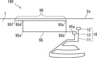
- FIG. 17 is a diagram showing a configuration example of the vehicle glass device 180 according to the second modification of the first embodiment, and includes an electric heating unit 10 and a linear element 95.
- the line element 95 is also referred to as a "first line element” or simply a "line element”.
- the linear element 95 is connected to the ground portion 13, and the point 95a is a contact point between the linear element 95 and the electric heating portion 10.
- the linear element 95 may be connected to the power feeding unit 12.
- the linear element 95 extends horizontally from point 95a to point 95b and constitutes a (rectangular) closed loop formed by a route returning to point 95b, point 95c, point 95d, point 95e and point 95b. Further, the linear element 95 extends horizontally from the point 95d to the point 95f in the vicinity of the end portion 2a of the conductive body 2. The portion of the linear element 95 from the point 95c to the point 95f constitutes a capacitive coupling portion 96 that is capacitively coupled to the end portion 2a of the conductive body 2.
- the linear element 95 is a linear element from a point 95a to a point 95b, a linear element from a point 95d to a point 95f, and a loop-shaped element forming a closed loop from the point 95b to the point 95e.
- Noise can be reduced as in the first embodiment even if the shapes are combined.
- the linear element 95 may have a shape that does not have a portion from the point 95d to the point 95f. That is, the linear element 95 may have a shape in which the linear element from the point 95a to the point 95b and the closed loop element described above are combined. Further, the linear element 95 may have a shape having no portion from the point 95a to the point 95b. That is, the linear element 95 may be connected to the ground portion 13 at the point 95b, and the closed loop element and the linear element from the point 95d to the point 95f may be connected to each other.
- FIG. 18 is a diagram showing a configuration example of the vehicle glass device according to the second embodiment, and is a partially enlarged view corresponding to FIG. 2.
- the vehicle glass device 200 includes an electric heating unit 10, a linear element 210, and a linear element 220. Since the electric heating unit 10 is the same as that of the first embodiment, the description thereof will be omitted.
- the linear elements 210 and 220 are non-heating elements as in the first embodiment, and are elements in which a direct current does not flow even if a direct current is applied between the power feeding unit 12 and the ground unit 13. is there.
- the first contact (with the electric heating unit 10) of the linear element 210 is connected to the power feeding unit 12, and the other end is an open end.
- the linear element 220 has a second contact (with the electric heating portion 10) at one end connected to the ground portion 13, and the other end is an open end.
- the contact point between the wire element 210 and the electric heating unit 10 is included in the power feeding unit 12, and the contact point between the wire element 220 and the electric heating unit 10 is included in the ground unit 13.
- the first contact may be located in the electric heating unit 10 as in the first embodiment, and the second contact may be located in the electric heating unit 10 as well. That is, in this example, the first contact is located at the power feeding unit 12 and the second contact is located at the ground unit 13, but the combination is not limited to this, and either the first contact or the second contact is used. Alternatively, both may be located on the heating wire 11.
- each of the linear elements 210 and 220 may have a shape including both an open end and a closed loop, or may have a shape including a closed loop without having an open end. Further, each of the linear elements 210 and 220 may have the same shape as the linear element 95 described in the second modification of the first embodiment. That is, each of the linear elements 210 and 220 may have a shape that includes at least one of an open end and a closed loop.
- the linear element 210 and the linear element 220 has a capacitive coupling portion 211 and a capacitive coupling portion 221, respectively. That is, the linear element 210 constitutes a conductor portion, and the portion of the linear element 220 close to the linear element 210 constitutes a capacitive coupling portion 221 that is capacitively coupled to the conductor portion. Further, the linear element 220 constitutes a conductor portion, and a portion of the linear element 210 in the vicinity of the linear element 220 constitutes a capacitive coupling portion 211 that is capacitively coupled to the conductor portion.
- a part of the two linear elements is close to each other, and each of the two linear elements uses the other linear element as a conductor portion. It constitutes a capacitive coupling portion that is capacitively coupled to the conductor portion.
- the vehicle glass device 200 has the capacitive coupling portions 211 and 221 that are capacitively coupled by the two linear elements 210 and 220, and thus has two paths including the following (2) in addition to the following (1). Therefore, the noise radiated (re) from the heating wire 11 can be reduced.
- (1) A route (connecting the DC power supply and the power supply unit 12), the power supply unit 12, the heating wire 11, the ground unit 13, and the electrical wiring (connecting the ground unit 13 to the ground conductor) in this order ( 2) Electrical wiring (connecting the DC power supply and the power supply unit 12), power supply unit 12, wire element 210 (capacitive coupling unit 211), wire element 220 (capacitive coupling unit 221), grounding unit 13 and (earthing unit 13).
- DC power supply Routes connected in the order of electrical wiring
- one of the linear element 210 and the linear element 220 is the first linear element and the other is the second linear element. That is, if the first wire element is a wire element connected to the power feeding unit 12, the second wire element is a wire element connected to the ground part 13, but the first wire element is connected to the ground part 13. If it is a linear element to be connected, the second linear element is a linear element connected to the power feeding unit 12. Further, in the present embodiment, the first line element and the second line element are also simply referred to as a "line element".
- the linear element 210 in the vehicle glass device 200 of FIG. 18 has one end connected to the feeding portion 12 and extends in the horizontal direction to have an open end, and the linear element 220 has one end connected to the ground portion 13.
- the linear element 210 and the linear element 220 were specifically set as follows. Distance of linear element 210: 75 mm Distance between the linear element 210 and the end 2a of the conductive body 2: 75 mm Distance of linear element 220 (capacitive coupling portion 211, 221): 54 mm Distance between the linear element 210 and the linear element 220: 10 mm
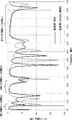
- FIG. 19 is a diagram showing a vehicle glass device according to a second embodiment and radio wave radiation characteristics of a default configuration.
- the value of the S11 parameter of the vehicle glass device 200 is larger than the value of the S11 parameter of the default configuration in the frequency band of DTV of 470 MHz to 550 MHz and 570 MHz to 710 MHz. Further, the value of the S11 parameter of the vehicle glass device 200 is larger than the value of the S11 parameter of the default configuration in the frequency band of DAB from 230 MHz to 240 MHz. That is, the vehicle glass device 200 can reduce noise in the DTV frequency band and the DAB frequency band as compared with the default configuration.
- the vehicle glass device 200 according to the second embodiment has a configuration in which the linear elements 210 and 220 are provided and the capacitive coupling portions 211 and 221 are provided by the linear elements 210 and 220, the heating wire 11 The radiated noise can be reduced.
- the total value of the frequency bands in which the value of the S11 parameter is equal to or less than the threshold value of -3 dB in the frequency band of the broadcast wave was 27 MHz.
- the total value of the frequency bands below the threshold value is 95 MHz, so that the vehicle glass device 200 can reduce the noise radiated from the heating wire 11 as compared with the default configuration.
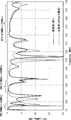
- FIG. 20 is a diagram showing a configuration example of the vehicle glass device 230 according to Example 9, and is a partially enlarged view corresponding to FIG. 2.
- FIG. 21 is a diagram showing the radio wave radiation characteristics of the vehicle glass device 230 according to Example 9 and the radio wave radiation characteristics of the default configuration.
- the vehicle glass device 230 includes an electric heating unit 10, a linear element 240, and a linear element 250.
- One of the linear element 240 and the linear element 250 is also referred to as a "first linear element” and the other is also referred to as a “second linear element”, and the linear element including the first linear element and the second linear element is simply ". Also called “straight element”.
- the shape of the linear element 240 connected to the ground portion 13 is different from that of the vehicle glass device 200 according to the second embodiment.
- the linear element 240 is connected to the ground portion 13, and the other end is an open end, and has a shape including a U-shape.
- the linear element 240 has a point 240a as a contact point between the linear element 240 and the ground portion 13, and extends horizontally from the point 240a to the point 240b.
- the linear element 240 extends vertically from the point 240b toward the point 240c toward the end 2a of the conductive body 2, and extends horizontally from the point 240c to the feeding portion 12 toward the point 240d. It extends in the approaching direction.
- the portion from the point 240c to the point 240d is arranged in parallel with the portion from the point 240a to the point 240b.
- One end of the linear element 250 is connected to the feeding portion 12 and extends in the horizontal direction, and the other end is an open end. At least a part of the linear element 250 extends inside the U-shape of the linear element 240 without coming into contact with the linear element 240 from the contact point with the feeding portion 12. That is, the linear element 250 extends in the horizontal direction from the contact point with the feeding portion 12 toward the portion from the point 240b to the point 240c without contacting the linear element 240.
- At least a part of the linear elements 240 and 250 has a capacitive coupling portion 241 and a capacitive coupling portion 242, and a capacitive coupling portion 251, respectively. That is, the linear element 250 constitutes a conductor portion, and the portion of the linear element 240 close to the linear element 250 constitutes the capacitive coupling portions 241 and 242 that are capacitively coupled to the conductor portion. Further, the linear element 240 constitutes a conductor portion, and the portion of the linear element 250 surrounded by a dotted line constitutes a capacitive coupling portion 251 that is capacitively coupled to the conductor portion.
- the vehicle glass device 230 has the capacitive coupling portion 241 and the capacitive coupling portion 242 and the capacitive coupling portion 251 to be capacitively coupled by the two linear elements 240 and 250, in addition to the following (1).
- the noise radiated (re) from the heating wire 11 can be reduced by the path including the following (2).
- a route (connecting the DC power supply and the power supply unit 12), the power supply unit 12, the heating wire 11, the ground unit 13, and the electrical wiring (connecting the ground unit 13 to the ground conductor) in this order ( 2) Electrical wiring (connecting DC power supply and power supply unit 12), power supply unit 12, linear element 250 (capacitive coupling unit 251), linear element 240 (capacitive coupling unit 241 and / or capacitive coupling unit 242), ground Route 13 and the electrical wiring (connecting the ground 13 and the DC power supply)
- one of the linear element 240 and the linear element 250 is the first linear element and the other is the second linear element. That is, if the first wire element is a wire element connected to the power feeding unit 12, the second wire element is a wire element connected to the ground part 13, but the first wire element is connected to the ground part 13. If it is a linear element to be connected, the second linear element is a linear element connected to the power feeding unit 12.
- the linear element 250 in the vehicle glass device 230 of FIG. 20 has one end connected to the feeding portion 12 and extends in the horizontal direction to have an open end, and the linear element 240 has an open end at one end. It has an open end in a U shape so as to surround it without being connected to the linear element 250.
- the linear element 240 and the linear element 250 were specifically set as follows. Distance from point 240a to point 240b: 52 mm Distance from point 240b to point 240c: 20 mm Distance from point 240c to point 240d: 68mm Distance between the element at points 240c to 240d and the end 2a of the conductive body 2: 65 mm Distance of linear element 250: 63 mm Distance of capacitive coupling part 251: 42 mm Distance between the linear element 250 (capacitive coupling portion 251) and the elements at points 240a to 240b: 10 mm Distance between the linear element 250 (capacitive coupling portion 251) and the element at points 240c to 240d: 10 mm
- FIG. 21 is a diagram showing radio wave radiation characteristics of the vehicle glass device 230 and the default configuration according to Example 9.
- the value of the S11 parameter of the vehicle glass device 230 is generally larger than the value of the S11 parameter of the default configuration in the frequency band of DTV.
- the value of the S11 parameter of the vehicle glass device 230 is larger than the value of the S11 parameter of the default configuration in the frequency band of DAB from 230 MHz to 240 MHz. That is, the vehicle glass device 230 can reduce noise in the DAB frequency band and the DTV frequency band as compared with the default configuration.
- the total value of the frequency bands in which the value of the S11 parameter is equal to or less than the threshold value of -3 dB in the frequency band of the broadcast wave was 27 MHz.
- the total value of the frequency band in which the value of the S11 parameter is equal to or less than the threshold value is 95 MHz, so that the vehicle glass device 230 can reduce the noise radiated from the heating wire 11.
- the linear element 250 has a U shape and surrounds the linear element 240
- the linear element 240 (second linear element) has an L-shaped shape including at least one bending point
- the linear element 250 (first linear element) has a linear including the bending point. It may have a bent shape so as to surround the element 240 (second line element).
- the capacitive coupling may be included in the second streak element and may be configured over two lines sharing the inflection point.
- the first line element is not limited to the U shape as long as it has a shape that matches the shape of the second line element and surrounds it without being connected to the second line element.
- the third embodiment is an embodiment in which the first embodiment and the second embodiment are combined.
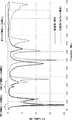
- FIG. 22 is a diagram showing a configuration example of the vehicle glass device according to the third embodiment, and is a partially enlarged view corresponding to FIG. 2.
- FIG. 23 is a diagram showing the radio wave radiation characteristics of the vehicle glass device 300 according to the present embodiment and the radio wave radiation characteristics of the default configuration.
- the vehicle glass device 300 includes an electric heating unit 10, a linear element 310, and a linear element 320.
- One of the linear element 310 and the linear element 320 is also referred to as a "first linear element” and the other as a "second linear element", and the linear element including the first linear element and the second linear element is simply ". Also called "straight element". Since the electric heating unit 10 is the same as that of the first embodiment, the description thereof will be omitted.
- the linear elements 310 and 320 are non-heatable elements as in the first embodiment and the second embodiment, and are DC even if a DC voltage is applied between the power feeding unit 12 and the ground unit 13. It is an element that does not allow current to flow.
- One end of the linear element 310 is connected to the ground portion 13, and the other end is an open end.
- the linear element 310 has the same shape as the linear element 40 in Example 3 described above.
- One end of the linear element 320 is connected to the feeding portion 12, and the other end is an open end.
- the contact point between the linear element 310 and the electric heating unit 10 is included in the grounding unit 13, and the contact point between the linear element 320 and the electric heating unit 10 is included in the power feeding unit 12.
- the linear elements 310 and 320 have a shape having an open end.
- each of the linear elements 310 and 320 may have a shape including both an open end and a closed loop, or may have a shape including a closed loop without having an open end. Further, each of the linear elements 310 and 320 may have the same shape as the linear element 95 described in the second modification of the first embodiment. That is, each of the linear elements 310 and 220 may have a shape that includes at least one of an open end and a closed loop. Alternatively, the linear element 310 may have the same shape as the linear element of the glass device according to any one of Examples 1, 3 to 7. That is, the linear element 310 may be replaced with the linear element of the glass device according to any one of Examples 1, 3 to 7.
- the linear element 310 has a capacitive coupling portion 311 in which a part thereof is capacitively coupled to the end portion 2a of the conductive body 2 (conductor portion). Further, the linear element 320 constitutes a capacitive coupling portion 312 in which a part thereof is capacitively coupled to the linear element 310 (conductor portion). That is, it can be said that the linear element 310 has a configuration including two capacitive coupling portions. Further, the linear element 310 includes a conductor portion, and a portion of the linear element 320 close to the linear element 310 constitutes a capacitive coupling portion 321 that is capacitively coupled to the conductor portion.
- the capacitive coupling portion 311 is capacitively coupled to the end portion 2a of the conductive body 2 by the linear element 310, and the capacitive coupling portion 312 is capacitively coupled by the two linear elements 310 and 320. And by having the capacitive coupling portion 321, it is possible to reduce the noise (re) radiated from the heating wire 11 by the path including the following (2) and the following (3) in addition to the following (1).
- a route (connecting the DC power supply and the power supply unit 12), the power supply unit 12, the heating wire 11, the ground unit 13, and the electrical wiring (connecting the ground unit 13 to the ground conductor) in this order ( 2)
- the electrical wiring (connecting the DC power supply and the power supply unit 12), the power supply unit 12, the heating wire 11, the ground unit 13, the wire element 310 (capacitive coupling unit 311), and the conductive body 2 of the vehicle are connected in this order.
- Path (3) Electrical wiring (connecting DC power supply and power supply unit 12), power supply unit 12, linear element 320 (capacitive coupling unit 321), linear element 310 (capacitive coupling unit 312), ground unit 13, and ( Route connected in the order of electrical wiring (connecting the ground unit 13 and DC power supply)
- one of the linear element 310 and the linear element 320 is the first linear element and the other is the second linear element. That is, if the first wire element is a wire element connected to the power feeding unit 12, the second wire element is a wire element connected to the ground part 13, but the first wire element is connected to the ground part 13. If it is a linear element to be connected, the second linear element is a linear element connected to the power feeding unit 12.
- the linear element 320 in the vehicle glass device 300 of FIG. 22 has an open end in an L-shape having one end connected to the feeding portion 12 and extending in the horizontal and vertical directions. Further, the linear element 310 in the vehicle glass device 300 has the same shape as the linear element 40 in Example 3.
- the linear element 310 and the linear element 320 were specifically set as follows.
- the value of the S11 parameter of the vehicle glass device 300 is larger than the value of the S11 parameter of the default configuration in the vicinity of 100 MHz in the FM frequency band. Further, the value of the S11 parameter of the vehicle glass device 300 is larger than the value of the S11 parameter of the default configuration in the frequency band of DAB from 230 MHz to 240 MHz. Further, the value of the S11 parameter of the vehicle glass device 300 is larger than the value of the S11 parameter of the default configuration in the frequency band of DTV of 470 MHz to 530 MHz and 555 MHz to 710 MHz. That is, the vehicle glass device 300 can reduce noise in the frequency band of the broadcast wave as compared with the default configuration.
- the total value of the frequency bands in which the value of the S11 parameter is equal to or less than the threshold value of -3 dB in the frequency band of the broadcast wave is 17 MHz. there were.
- the total value of the frequency bands in which the value of the S11 parameter is equal to or less than the threshold value is 95 MHz, so that the vehicle glass device 300 can reduce noise as compared with the default configuration.
- the table shown below is a table summarizing the evaluation results of the radio wave radiation characteristics of the vehicle glass device according to the first to third embodiments.
- the value of the S11 parameter is -3 dB in the broadcast wave frequency band and the frequency band of 50 MHz to 1600 MHz. The total value of the frequency band below the threshold value is shown.
- the ALL Band column lists the total value of the frequency bands in which the value of the S11 parameter is below the threshold of -3 dB in all frequency bands from 50 MHz to 1600 MHz. Further, in the column of Broadcast Band, the total value of the frequency band in which the value of the S11 parameter is equal to or less than the threshold value of -3 dB in the frequency band of the broadcast wave is described.
- the vehicle glass devices 100, 120 to 160, 200, 230, and 300 have smaller numerical values than the default configuration in the frequency band of the broadcast wave, so that the noise can be reduced as compared with the default configuration. ..
- the vehicle glass device 300 according to the third embodiment is a configuration that combines the configurations of the vehicle glass device according to the first embodiment and the second embodiment, and is the most noisy in the frequency band of the broadcast wave. The result was that Further, the vehicle glass device 300 according to the third embodiment has the result that the noise can be reduced most even in All Band.
- the vehicle glass device 300 since the vehicle glass device 300 includes the linear elements 310 and 320 and each of the linear elements 310 and 320 has a capacitive coupling portion, noise radiated from the heating wire 11 is generated. Can be reduced. Further, since the vehicle glass device 300 has a configuration in which the configurations of the vehicle glass device according to the first embodiment and the second embodiment are combined, the electric power is higher than that of the first embodiment and the second embodiment. The noise radiated from the heat ray 11 can be reduced. That is, the linear element 310 is arranged close to the end portion 2a of the conductive body 2 and the linear element 320, and the linear element 320 is arranged close to the linear element 310, so that the heating wire 11 The radiated noise can be reduced. Therefore, according to the vehicle glass device 300 according to the third embodiment, the noise radiated from the heating wire 11 can be reduced with a simple configuration.
Abstract
簡便な構成で電熱線から放射されるノイズを低減できる車両用ガラス装置を提供する。車両用ガラス装置(100)は、ガラス板(1)の平面視において、情報デバイスの信号を透過する透過領域Rに少なくとも一部が配置される電熱線(11)と、電熱線(11)に接続される第1端子及び第2端子とを含む電熱部(10)と、電熱部(10)と接続する線条エレメントと、を備える。線条エレメントは、電熱部(10)の第1接点と接続して延在する線条エレメント(20)、を有し、線条エレメント(20)は、導体部と容量結合する容量結合部(21)を含み、開放端及び閉ループの少なくとも1つを含む形状である。
Description
本発明は、車両用ガラス装置に関する。
近年、自動車には、フロントガラス(ウィンドシールド)、ダッシュボード等に、車内外の状況を記録するための撮像装置が標準的に取り付けられる傾向がある。また、撮像装置以外にも、衝突防止等の目的で車外の障害物を検知する等のセンサを含む安全機能を備える装置が自動車に導入されることも検討されている。
撮像装置は、運転者の視界を妨げないように、例えば、フロントガラスの上部に取り付けられる構成が挙げられる。撮像装置が取り付けられるフロントガラスの撮像領域は、撮像装置が車外の状況をクリアに撮像するため、例えば、可視光を透過する透過領域内に配置される。また、当該撮像領域は、車外の気候の状況によっては、霜や氷が付着したり、曇りが生じたりしてしまうことがある。撮像領域に霜や氷が付着したり、曇りが生じたりしてしまうと、撮像装置が撮像した画像の品質は劣化してしまう。そこで、撮像装置が撮像する画像の品質劣化を防ぐために、撮像領域には、電熱線(ヒータ線)が配置される場合がある。電熱線(ヒータ線)は、直流電圧が印加され、電熱線の抵抗によって加熱されることにより、防氷、防曇の効果が得られる(例えば、特許文献1~3)。
撮像装置等は、内部に電子回路等を備えている。この電子回路は、動作時に設計上意図しない電磁波を発生し、この電磁波はいわゆるノイズである。ノイズは、電子回路から直接放射されるか、または、電子回路近傍の導体を介して車両内に伝わる。とくに、撮像装置においては、該装置のノイズが電熱線に伝わりやすく、これが電熱線に伝わると電熱線から再放射される。このような現象から、電熱線は、副次的(不可避的)に、所定の周波数のノイズを放射するノイズ発生源となってしまう。
ここで、撮像装置の近傍には、例えば、AMやFM、欧州規格のDAB(Digital Audio Broadband)、DTV(Digital Television)等の2GHz未満の周波数帯域の放送波を受信するアンテナ(電装品)が集約される場合があり得る。電熱線(ヒータ線)から放射されるノイズは、例えば、上記の放送波の周波数帯域のノイズを含み得るため、放送波の受信感度を劣化させたり、また、放送波の周波数帯域以外の周波数帯域であっても、車車間通信のセンサ等に影響を及ぼしたりするおそれがあり、誤動作を引き起こす原因ともなりかねない。
本発明は、簡便な構成で電熱線から放射されるノイズを低減できる車両用ガラス装置を提供することを目的とする。
本発明は、以下[1]~[12]の構成を有する車両用ガラス装置を提供する。
[1]
車両用のガラス板と、
前記ガラス板の平面視において、情報デバイスの信号を透過する透過領域に少なくとも一部が配置される電熱線と、前記電熱線に接続される第1端子及び第2端子とを含む電熱部と、
前記電熱部と接続する線条エレメントと、を備え、
前記線条エレメントは、前記電熱部の第1接点と接続して延在する第1線条エレメントを有し、
前記第1線条エレメントは、導体部と容量結合する容量結合部を含み、開放端及び閉ループの少なくとも1つを含む形状である、車両用ガラス装置。
[1]
車両用のガラス板と、
前記ガラス板の平面視において、情報デバイスの信号を透過する透過領域に少なくとも一部が配置される電熱線と、前記電熱線に接続される第1端子及び第2端子とを含む電熱部と、
前記電熱部と接続する線条エレメントと、を備え、
前記線条エレメントは、前記電熱部の第1接点と接続して延在する第1線条エレメントを有し、
前記第1線条エレメントは、導体部と容量結合する容量結合部を含み、開放端及び閉ループの少なくとも1つを含む形状である、車両用ガラス装置。
[2]前記導体部は、前記第1端子、前記第2端子、前記電熱線、及び前記ガラス板が取り付けられる車両の導電性ボディの端部の少なくとも1つを用いて構成される、[1]に記載の車両用ガラス装置。
[3]前記第1接点は、前記第1端子に含まれる、[1]又は[2]に記載の車両用ガラス装置。
[4]
前記線条エレメントは、前記第1接点と異なる前記電熱部の第2接点と接続して延在し、開放端及び閉ループの少なくとも1つを含む形状である第2線条エレメントをさらに備え、
前記導体部は、前記第1端子、前記第2端子、前記電熱線及び前記ガラス板が取り付けられる車両の導電性ボディの端部、及び前記第2線条エレメントの少なくとも1つを用いて構成される、[1]~[3]のいずれか1項に記載の車両用ガラス装置。
前記線条エレメントは、前記第1接点と異なる前記電熱部の第2接点と接続して延在し、開放端及び閉ループの少なくとも1つを含む形状である第2線条エレメントをさらに備え、
前記導体部は、前記第1端子、前記第2端子、前記電熱線及び前記ガラス板が取り付けられる車両の導電性ボディの端部、及び前記第2線条エレメントの少なくとも1つを用いて構成される、[1]~[3]のいずれか1項に記載の車両用ガラス装置。
[5]前記第2接点は、前記第2端子に含まれる、[4]に記載の車両用ガラス装置。
[6]前記線条エレメントは、前記第1線条エレメントが前記第2線条エレメントを囲うようにして、互いに接続せずに前記容量結合部を形成する、[4]又は[5]に記載の車両用ガラス装置。
[7]
前記第1線条エレメントは、U字形状を含み、
前記第2線条エレメントの少なくとも一部は、前記U字形状の内部に延在する、[6]に記載の車両用ガラス装置。
前記第1線条エレメントは、U字形状を含み、
前記第2線条エレメントの少なくとも一部は、前記U字形状の内部に延在する、[6]に記載の車両用ガラス装置。
[8]前記第1端子はアース部であり、前記第2端子は給電部である、[1]~[7]のいずれか1項に記載の車両用ガラス装置。
[9]前記容量結合部と、前記導体部とは、30mm以下の間隔で近接している、[1]~[8]のいずれか1項に記載の車両用ガラス装置。
[10]前記容量結合部は、20mm以上の長さを有する、[1]~[9]のいずれか1項に記載の車両用ガラス装置。
[11]前記ガラス板は、平面視において、前記線条エレメントの少なくとも一部と重なるように設けられ、可視光を遮断する遮光部をさらに備える、[1]~[10]のいずれか1項に記載の車両用ガラス装置。
[12]前記ガラス板は、前記車両用のフロントガラスである、[1]~[11]のいずれか1項に記載の車両用ガラス装置。
本発明の一態様によれば、簡便な構成で電熱線から放射されるノイズを低減できる車両用ガラス装置を提供できる。
以下、本発明を適用した具体的な実施形態について、図面を参照しながら詳細に説明する。但し、本発明が以下の実施形態に限定されない。また、説明を明確にするため、以下の記載及び図面は、適宜、省略、及び簡略化がなされている。また、各図面において、同一の要素には同一の符号が付されており、必要に応じて重複説明は省略されている。なお、各実施形態において、平行、水平、垂直などの方向には、本発明の効果を損なわない程度のずれが許容される。
(第1の実施形態)
図1及び図2を用いて、第1の実施形態にかかる車両用ガラス装置100の構成例について説明する。
[例1]
図1は、第1の実施形態(例1)にかかる車両用ガラス装置の構成例を示す全体概略図であり、フロントガラスが自動車に取り付けられた状態の車外視の図である。図2は、第1の実施形態(例1)にかかる車両用ガラス装置の構成例を示す拡大図である。
図1及び図2を用いて、第1の実施形態にかかる車両用ガラス装置100の構成例について説明する。
[例1]
図1は、第1の実施形態(例1)にかかる車両用ガラス装置の構成例を示す全体概略図であり、フロントガラスが自動車に取り付けられた状態の車外視の図である。図2は、第1の実施形態(例1)にかかる車両用ガラス装置の構成例を示す拡大図である。
車両用ガラス装置100は、自動車等の車両の窓ガラスに配置される装置である。図1に示すように、車両用ガラス装置100は、例えば、自動車のフロントガラスに配置される。車両用ガラス装置100は、ガラス板1と、電熱部10と、線条エレメント20とを備える。
ガラス板1は、車両用ガラス装置100が配置される窓ガラスであり、例えば、車両用のフロントガラスである。ガラス板1は、車両の導電性ボディ2に取り付けられており、車体筐体に形成されたボディフランジに固定される。なお、導電性ボディ2は、主に金属ボディが挙げられるが、導電性を有する材料であれば金属に限らずカーボン等でもよい。図1において、ガラス板1の中央上部の車内側には、図示しない撮像装置等の情報デバイスが備えられる。そして、ガラス板1は、情報デバイスの信号を透過するための透過領域Rが設けられる。なお、図1、図2において、透過領域Rは、上辺の長さよりも下辺の長さが長い六角形の領域を例示しているが、透過領域Rは任意の形状に設定できる。
ここで、透過領域Rは、車内に設置された情報デバイスが、車外からガラス板1を透過して電波を受信したり、車外へガラス板1を透過して信号を送信したりするときに、ガラス板1において、少なくとも該信号の透過領域を含む領域として定義できる。また、図1に示すように、車両用ガラス装置100は、平面視において、ガラス板1の透過領域Rの周辺に可視光を遮断する遮光部3を有してもよい。この場合、透過領域Rは、電熱線11を含むとともに遮光部3の内縁で囲まれた領域として定義してもよい。なお、図1に示すように、遮光部3は、ガラス板1の平面視で透過領域Rを囲うとともに、ガラス板1の全ての外周縁から内側に所定の幅を有する連続的な領域を例示できるが、この構成に限らない。また、遮光部3は、後述する各例の線条エレメントの少なくとも一部と重なるように配置されると、線条エレメントが視認されにくくなることで見栄えがよくなり好ましく、線条エレメント全てと重なるように配置されるとより好ましい。さらに、視認されにくい効果を高めるために、遮光部3は、後述する給電部12とアース部13の少なくとも一方と重なるとより好ましく、給電部12とアース部13の両方と重なるとさらに好ましい。
また、遮光部3は、具体的にガラス板1の面に遮光膜が形成され、該遮光膜としては、例えば、黒色セラミックス等のセラミックスを使用できる。とくに、ガラス板1がフロントガラスの場合、ガラス板1は、第1のガラス板と第2のガラス板で中間膜を挟んだ、いわゆる合わせガラスが用いられる。中間膜としては、ポリビニルブチラール(PVB)、エチレン酢酸ビニル共重合体(EVA)等が使用できる。また、ガラス板1が合わせガラスであって、ガラス板1の車外から車内に向かって、第1のガラス板、中間膜および第2のガラス板がこの順に積層されている場合、遮光膜は、第2のガラス板の車内側(中間膜とは反対側)の表面、および/または、第1のガラス板の中間膜側の表面に形成できる。なお、本明細書では、ガラス板1は、車両用のフロントガラスとして記載をするが、フロントガラス以外の車両用の窓ガラス(例えば、リアガラス)でもよい。さらに、透過領域Rは、ガラス板1の中央上部の場所に設けられることとして記載をするが、ガラス板1の中央上部以外の場所に設けられてもよい。
次に、図2を参照して、電熱部10及び線条エレメント20について説明する。図2は、図1に示す車両用ガラス装置100のうち、透過領域R、電熱部10及び線条エレメント20が含まれる部分を拡大した図である。なお、以降の説明において、方向を示す記載が含まれるが、当該方向は、ガラス板1の平面視における方向を示している。
電熱部10は、透過領域Rの防氷及び防曇を目的として設けられ、電熱線11と、給電部12と、アース部13とを含む。なお、本明細書において、給電部12とアース部13の組合せは、第1端子と第2端子ともいう。つまり、第1端子が給電部12であれば、第2端子がアース部13であり、第1端子がアース部13であれば、第2端子が給電部12である。電熱線11は、少なくとも一部が透過領域Rに配置される。なお、ガラス板1の平面視における電熱線11の配置パターンは、透過領域Rの大きさや外縁形状に応じ、防氷及び防曇効果を発揮するとともに、例えば、情報デバイスとして可視光の映像信号を受信する撮像装置への映り込みが無視できる程度の密度で適宜配置できる。電熱線11は、給電部12から直流電圧が印加され、電熱線11の抵抗によって加熱されることで、透過領域Rを加熱する。また、給電部12およびアース部13は、図示しない電気配線(ハーネス等)を介して、透過領域R近傍から離れて配置される直流電源へ接続される。なお、アース部13に接続される側のアース部側電気配線は、直流電源付近に接続してアースを取る配置でもよく、導電性ボディ2の任意の位置に接続してアースを取る配置でもよい。電熱線11は、図示しない撮像装置等の情報デバイス内の電子回路等からノイズが入力されると、入力されたノイズは、電熱線11を介して再放射される。
次に、透過領域Rの近傍に、FM、DAB、及びDTVの周波数帯域の放送波を受信するアンテナが配置される構成について考える。電熱線11を介して放射される電波は、例えば、FM、DAB及びDTVの放送波を受信するアンテナ等に対するノイズとなり得る。FMの周波数帯域は、76MHz~108MHzであり、DAB(Band III)の周波数帯域は、174MHz~240MHzであり、DTVの周波数帯域は、470MHz~710MHzである。なお、以降の説明において、76MHz~108MHz、174MHz~240MHz及び470MHz~710MHzをあわせた周波数帯域を「放送波の周波数帯域」と称する。なお、DABは、「Band III」(174MHz~240MHz)と「L-Band」(1452MHz~1492MHz)の規格があるが、本明細書ではとくにことわりがない場合、「Band III」の周波数帯域として説明する。
なお、透過領域Rの近傍に配置されるアンテナは、上記放送波用に限らず、760MHzの周波数帯域のITS(Intelligent Transport Systems)用のアンテナでもよく、4G LTE(Long Term Evolution)から5G-sub6の周波数帯域の通信インフラの利用に合わせたアンテナでもよい。4G LTE用アンテナとしては、4G LTEのグローバルで使用される周波数帯として698MHz~960MHz、1790MHz~2690MHzの電波を送受するアンテナが例示できる。また、5G-sub6として、5.9GHzの周波数帯を送受し車車間通信および路車間通信に用いられるV2X(Vehicle to Everything)対応アンテナ、C(Cellular)-V2X対応アンテナも例示できる。このように、透過領域Rの近傍に配置されるアンテナは、4Gから5G-sub6までの700MHz~6GHzにわたる任意の周波数帯の電波を送受できるアンテナが挙げられる。さらに、透過領域Rの近傍に配置されるアンテナは、5Gとして6GHz以上の周波数帯域の電波を送受する、高速かつ大容量の通信インフラの利用に合わせたC2X対応アンテナでもよく、例えば、28GHzの周波数帯の電波を送受するアンテナでもよい。
電熱線11は、透過領域Rを加熱するように配置されており、ガラス板1を車両に取り付けた際に、透過領域Rがガラス板1の上部に位置するとき、例えば、次のように配置できる。電熱線11は、給電部12から垂直方向の下向きに延び、点11aから水平方向に透過領域R内に向けて延びている。電熱線11は、透過領域R内では、点11aから点11bまで、直線状のパーツがS字状に連結された形状となっており、点11bから点11cまでは、透過領域Rの外縁と略平行に配置される。電熱線11は、点11cからアース部13に向けて垂直方向の上向きに延びて配置される。なお、電熱線11は、透過領域Rを加熱するように配置されていればよいため、上記のような形状に限らない。なお、ガラス板1が合わせガラスの場合、例えば、電熱線11は、第2のガラス板の中間膜とは反対側の表面(車内側の表面)に配置できる。また、ガラス板1が、第2のガラス板の中間膜とは反対側の表面、および/または、第1のガラス板の中間膜側の表面に遮光膜が形成される場合も、電熱線11は、第2のガラス板の中間膜とは反対側の表面(車内側の表面)に配置できる。
給電部12およびアース部13は、電熱線11と接続する端子であり、これらの端子間に電位差を与え、電熱線11に直流電圧を印加する。なお、図1、図2において、電熱線11が加熱できれば、給電部12とアース部13との位置が置き換わった構成でもよい。
線条エレメント20は、非加熱性のエレメント(導線)であり、上記の端子間に直流電圧が印加されても直流電流が流れないエレメントである。図2の例では、線条エレメント20は、それの一端である(電熱部10との)第1接点がアース部13に接続されており、他端が開放端となっている。なお、本実施形態では、線条エレメント20の一端がアース部13に接続される構成として説明するが、線条エレメント20の一端が給電部12に接続される構成でもよい。つまり、線条エレメント20は、給電部12及びアース部13のうち、いずれか一方の端子と接続される構成でもよい。さらに、線条エレメント20の一端、つまり第1接点は、電熱部10に位置していればよく、給電部12及びアース部13に限らず、電熱線11に位置してもよく、以降の実施形態においても、給電部12及びアース部13に限らず、電熱線11に第1接点を位置させてもよい。また、本実施形態の車両用ガラス装置100において、(第1接点と接続する)1つのみ存在する線条エレメント20は、「第1線条エレメント」又は、単に「線条エレメント」ともいう。
例1において、線条エレメント20は、L字状の形状をしており、一部が導電性ボディ2の端部2aと、例えば、30mm以下で導電性ボディ2と接しない間隔で近接して配置される。具体的には、線条エレメント20は、点20aを線条エレメント20と電熱部10との接点(第1接点)とし、点20aから点20bまで垂直方向に導電性ボディ2の端部2aに近づく方向に延在し、点20bから点20cまで導電性ボディ2の端部2aと近接して、アース部13から遠ざかる方向で水平方向に延在している。
線条エレメント20のうち、導電性ボディ2の端部2aと近接する部分(点20bから点20cまでの部分)は、容量結合部21を構成する。つまり、導電性ボディ2の端部2aは導体部を構成し、線条エレメント20の容量結合部21は、該導体部と所定の容量値により容量結合される。換言すると、容量結合部21は、導電性ボディ2の端部2aを導体部として高周波的に接続されており、導電性ボディ2との間隔が0mm超30mm以下の部分として定義できる。
このように、車両用ガラス装置100は、容量結合部21を設けることで、発生したノイズが容量結合部21を介して導電性ボディ2に高周波的に接続されるため、電熱線11から(再)放射されるノイズを低減できる。具体的には、不図示の直流電源は、不図示の電気配線(ハーネス等)を介して給電部12、アース部13に接続されるが、線条エレメント20を配置することで、下記(1)に加え、下記(2)を含む経路によって放射ノイズを低減できる。ここで、下記(1)の経路に記載する「接地導体」とは、車両の金属ボディ等のアース電位と等価となる任意の導体部分を指す。
(1)(直流電源と給電部12を接続する)電気配線、給電部12、電熱線11、アース部13、そして(アース部13から接地導体へ接続する)電気配線の順に接続される経路
(2)(直流電源と給電部12を接続する)電気配線、給電部12、電熱線11、線条エレメント20(容量結合部21)そして車両の導電性ボディ2の順に接続される経路
(1)(直流電源と給電部12を接続する)電気配線、給電部12、電熱線11、アース部13、そして(アース部13から接地導体へ接続する)電気配線の順に接続される経路
(2)(直流電源と給電部12を接続する)電気配線、給電部12、電熱線11、線条エレメント20(容量結合部21)そして車両の導電性ボディ2の順に接続される経路
なお、ガラス板1の平面視において、導電性ボディ2の端部2aは、ガラス板1の端部よりも内側に配置されて、線条エレメント20の容量結合部21が導電性ボディ2に隠れる場合がある。この場合でも、容量結合部21と導電性ボディ2とは、ガラス板1の厚さ方向に間隙を有するので、この間隙が0mm超30mm以下であればよい。容量結合部21は、例えば、20mm以上の長さを有しており、電熱線11の配置及び電熱線11の長さにより、容量結合部21の長さを適宜調整できる。容量結合部21の長さは、20mm以上が好ましく、50mm以上がより好ましい。また、容量結合部21の長さはとくに制限はないが、線条エレメント20が必要以上に長くならない程度であればよく、例えば600mm以下であればよい。なお、容量結合部21と導電性ボディ2の端部2aとの間隔は、0mm超20mm以下が好ましく、0mm超10mm以下がより好ましい。なお、導体部と容量結合部21との間隔、容量結合部21の長さについては、後述する各例、各実施形態においても同様の範囲で設定するとよい。
次に、車両用ガラス装置100の電波放射特性について説明する。車両用ガラス装置100の電波放射特性を評価するため、線条エレメント20を備える車両用ガラス装置100と、車両用ガラス装置100に対して、線条エレメント20を有さない構成との電波放射特性を比較して説明する。なお、以降の説明において、車両用ガラス装置100に対して、線条エレメント20を有さない構成、すなわち、ガラス板1に電熱部10のみ有する構成を「デフォルト構成」と称する。
ここで、車両用ガラス装置100と、デフォルト構成との特性を比較するため、50MHzから1600MHzまでの周波数帯域におけるS11パラメータの値をシミュレーションで算出し、算出されたS11パラメータの値を電波放射特性とした。具体的に、車両用ガラス装置100と、デフォルト構成とについて、給電部12から電熱線11に入力される信号の電力と、アース部13から出力される信号の電力とに基づいて、上記周波数帯域におけるS11パラメータの値を算出した。
まず、50MHz~1600MHzまでの周波数帯域のうち、上記に定義した「放送波の周波数帯域」において、電熱線11から放射されるノイズの大きさを確認するために、S11パラメータの閾値を-3dBとして設定した。そして、車両用ガラス装置100と、デフォルト構成とについて、S11パラメータの値が閾値以下となる周波数帯域の合計値を算出することで、車両用ガラス装置100(線条エレメント20)の効果を評価した。なお、図2の車両用ガラス装置100における線条エレメント20は、具体的に、以下のように設定した。
点20a~点20bの距離:75mm
点20b~点20c(容量結合部21)の距離:300mm
容量結合部21と導電性ボディ2の端部2aとの間隔:10mm
点20a~点20bの距離:75mm
点20b~点20c(容量結合部21)の距離:300mm
容量結合部21と導電性ボディ2の端部2aとの間隔:10mm
また、電熱部10は、各々以下のような配置とした。なお、電熱部10の配置については、後述の[例2]以降も同じである。
導電性ボディ2の端部2a~給電部12の距離:60mm
導電性ボディ2の端部2a~アース部13の距離:85mm
給電部12の領域:21mm×14mm
アース部13の領域:21mm×14mm
給電部12~点11aの距離:65mm
アース部13~点11cの距離:30mm
点11a~点11cの距離:950mm
透過領域Rにおける電熱線11の上下(垂直)方向の長さ:160mm
透過領域Rにおける電熱線11の左右(水平)方向の長さ:200mm
導電性ボディ2の端部2a~給電部12の距離:60mm
導電性ボディ2の端部2a~アース部13の距離:85mm
給電部12の領域:21mm×14mm
アース部13の領域:21mm×14mm
給電部12~点11aの距離:65mm
アース部13~点11cの距離:30mm
点11a~点11cの距離:950mm
透過領域Rにおける電熱線11の上下(垂直)方向の長さ:160mm
透過領域Rにおける電熱線11の左右(水平)方向の長さ:200mm
図3は、第1の実施形態(例1)にかかる車両用ガラス装置100の電波放射特性(実施例)、及びデフォルト構成の電波放射特性(比較例)を示す図である。なお、放送波の周波数帯域の電波放射特性を確認するために、図3には、放送波の周波数帯域を含む70MHz~720MHzの電波放射特性のみを記載している。また、以降に示す電波放射特性の図についても同様に、放送波の周波数帯域を含む70MHz~720MHzの電波放射特性のみを記載し、その他の周波数範囲については図示を省略する。
図3において、実線は、車両用ガラス装置100の電波放射特性を示す線であり、点線は、デフォルト構成の電波放射特性を示す線である。なお、後述する電波放射特性を示す図(グラフ)についても、実線は各例にかかる車両用ガラス装置の電波放射特性を示し、点線はデフォルト構成の電波放射特性を示す。横軸は周波数を示しており、縦軸はS11パラメータの値を示している。図3に示すように、本例の車両用ガラス装置100のS11パラメータの値は、とくにFMの周波数帯域において、デフォルト構成のS11パラメータの値よりも全体的に大きい。S11パラメータの値が大きいことは、電熱線11からノイズの放射が小さいことを表しており、本例の車両用ガラス装置100は、とくにFMの周波数帯域において、デフォルト構成よりもノイズを低減できる。
この結果に基づくと、車両用ガラス装置100について、放送波の周波数帯域のうち、S11パラメータの値が-3dBの閾値以下となる周波数帯域の合計値は74MHzであった。一方、デフォルト構成について、放送波の周波数帯域のうち、閾値以下となる周波数帯域の合計値は95MHzであった。ここで、閾値以下となる周波数帯域の合計値が小さいほど、電熱線11からのノイズ放射が少ないことを表しており、線条エレメント20を備える車両用ガラス装置100は、デフォルト構成よりも算出した合計値が小さく、ノイズを低減できる。
ここで、図4及び図5を用いて、比較例である例2にかかる車両用ガラス装置110について説明する。
[例2](比較例)
図4は、例2にかかる車両用ガラス装置110の構成例を示す図であり、図2に対応する部分拡大図である。図5は、例2にかかる車両用ガラス装置110、及びデフォルト構成の電波放射特性を示す図である。
[例2](比較例)
図4は、例2にかかる車両用ガラス装置110の構成例を示す図であり、図2に対応する部分拡大図である。図5は、例2にかかる車両用ガラス装置110、及びデフォルト構成の電波放射特性を示す図である。
図4に示すように、例2にかかる車両用ガラス装置110は、車両用ガラス装置100と同様に、電熱部10及び線条エレメント30を備える。なお、図4及び以降の車両用ガラス装置の構成例を示す図において、簡略化するために、透過領域R及び遮光部3の図示を省略する。線条エレメント30は、一端が給電部12に接続され水平方向に延在しており、他端が開放端となっている。線条エレメント30は、線条エレメント20と異なり、導電性ボディ2の端部2aに近接して配置されておらず、容量結合部を備えない構成である。なお、図4の車両用ガラス装置100における線条エレメント30は、具体的に、以下のように設定した。
線条エレメント30の長さ:150mm
線条エレメント30と導電性ボディ2の端部2aとの間隔:60mm
線条エレメント30の長さ:150mm
線条エレメント30と導電性ボディ2の端部2aとの間隔:60mm
図5は、比較例である例2にかかる車両用ガラス装置110及びデフォルト構成の電波放射特性を示す図である。図5に示すように、車両用ガラス装置110は、デフォルト構成と同様の電波放射特性となった。つまり、車両用ガラス装置110は、車両用ガラス装置100がノイズを低減可能なFMの周波数帯域において、顕著にノイズを低減できない。このように、車両用ガラス装置110は、線条エレメント30を備える構成であるが、容量結合部を有さない構成であるため、車両用ガラス装置100よりも顕著にノイズを低減できない。
次に、比較例である例2にかかる車両用ガラス装置110について、例1と同様に、放送波の周波数帯域において、S11パラメータの値が-3dBの閾値以下となる周波数帯域の合計値を算出した。この結果に基づくと、放送波の周波数帯域において、車両用ガラス装置110のS11パラメータの値が閾値以下となる周波数帯域の合計値は90MHzであった。車両用ガラス装置110は、線条エレメント30を備える構成であるが、容量結合部を有さない構成であるため、車両用ガラス装置100と比較しても顕著にノイズを低減できない。
以上説明したように、例1(実施例)、例2(比較例)について要約すると、車両用ガラス装置100は、線条エレメント20を備え、線条エレメント20が容量結合部21を備える構成であるため、電熱線11から放射されるノイズを低減できる。一方で、車両用ガラス装置110は、線条エレメント30が容量結合部を備えない構成であるため、電熱線11から放射されるノイズを顕著に低減できない。
以下、第1の実施形態にかかる車両用ガラス装置100の他の構成例を説明する。
[例3]
図6は、例3にかかる車両用ガラス装置120の構成例を示す図であり、図2に対応する部分拡大図である。図7は、例3にかかる車両用ガラス装置120の電波放射特性、及びデフォルト構成の電波放射特性を示す図である。
[例3]
図6は、例3にかかる車両用ガラス装置120の構成例を示す図であり、図2に対応する部分拡大図である。図7は、例3にかかる車両用ガラス装置120の電波放射特性、及びデフォルト構成の電波放射特性を示す図である。
図6に示すように、車両用ガラス装置120は、電熱部10と、線条エレメント40とを備える。線条エレメント40は、「第1線条エレメント」又は、単に「線条エレメント」ともいう。線条エレメント40は、一端がアース部13に接続され、他端が開放端となっている。つまり、線条エレメント40と電熱部10との接点はアース部13に含まれており、線条エレメント40は、開放端を有する形状をしている。線条エレメント40は、線条エレメント20と同様に、一部が導電性ボディ2の端部2aと近接する部分(導体部)と容量結合する容量結合部41を構成する。
線条エレメント40は、線条エレメント20と異なり、容量結合部41を構成する部分に開放端が含まれず、容量結合部41からさらに線条エレメントが延在する構成であり、略C字状の形状をしている。具体的には、線条エレメント40は、点40aを線条エレメント40と電熱部10との接点とし、点40aから点40bに向けて垂直方向に導電性ボディ2の端部2aに近づく方向に延在する。そして、線条エレメント40は、点40bから点40cまで水平方向に導電性ボディ2の端部2aと近接してアース部13から遠ざかる方向に延在し、点40bから点40cまでの部分が容量結合部41を構成する。さらに、線条エレメント40は、点40cから点40dまで垂直方向に導電性ボディ2の端部2aから遠ざかる方向に延在し、点40dから点40eまで水平方向にアース部13に近づく方向に延在している。なお、図6の車両用ガラス装置120における線条エレメント40は、具体的に、以下のように設定した。
点40a~点40bの距離:75mm
点40b~点40c(容量結合部41)の距離:300mm
容量結合部41と導電性ボディ2の端部2aとの間隔:10mm
点40c~点40dの距離:150mm
点40d~点40eの距離:100mm
点40a~点40bの距離:75mm
点40b~点40c(容量結合部41)の距離:300mm
容量結合部41と導電性ボディ2の端部2aとの間隔:10mm
点40c~点40dの距離:150mm
点40d~点40eの距離:100mm
図7に示すように、車両用ガラス装置120のS11パラメータの値は、FMの周波数帯域において全体的にデフォルト構成のS11パラメータの値よりも大きい。すなわち、車両用ガラス装置120は、FMの周波数帯域においてデフォルト構成よりもノイズを低減できる。このように、車両用ガラス装置120が備える線条エレメント40が、容量結合部41を構成する部分からさらに延在する(略C字状の)構成としても、車両用ガラス装置100と同様に、簡便な構成で電熱線11から放射されるノイズを低減できる。
この結果に基づくと、車両用ガラス装置120について、放送波の周波数帯域のうち、S11パラメータの値が-3dBの閾値以下となる周波数帯域の合計値は61MHzであった。上記のように、デフォルト構成では、S11パラメータの値が閾値以下となる周波数帯域の合計値は95MHzであるため、車両用ガラス装置120は、電熱線11から放射されるノイズを低減できる。
[例4]
図8は、例4にかかる車両用ガラス装置130の構成例を示す図であり、図2に対応する部分拡大図である。図9は、例4にかかる車両用ガラス装置130の電波放射特性、及びデフォルト構成の電波放射特性を示す図である。
図8は、例4にかかる車両用ガラス装置130の構成例を示す図であり、図2に対応する部分拡大図である。図9は、例4にかかる車両用ガラス装置130の電波放射特性、及びデフォルト構成の電波放射特性を示す図である。
図8に示すように、車両用ガラス装置130は、電熱部10と、線条エレメント50とを備える。線条エレメント50は、「第1線条エレメント」又は、単に「線条エレメント」ともいう。線条エレメント50は、一端がアース部13に接続され、他端が開放端となっている。線条エレメント50は、線条エレメント20と同様に、一部が導電性ボディ2の端部2aと近接する部分(導体部)と容量結合する容量結合部51を構成する。
線条エレメント50は、線条エレメント20と形状が異なり、略J字状又は略C字状の形状をしている。具体的には、線条エレメント50は、点50aを線条エレメント50と電熱部10との接点とし、点50aから点50bに向けて水平方向に延在する。そして、線条エレメント50は、点50bから点50cまで垂直方向に導電性ボディ2の端部2aに近づく方向に延在し、点50cから点50dまで水平方向に導電性ボディ2の端部2aと近接しながら延在している。線条エレメント50は、透過領域R(電熱部10)の上部において導電性ボディ2の端部2aと近接し、点50cから点50dまでの部分が容量結合部51を構成する。なお、図8の車両用ガラス装置130における線条エレメント50は、具体的に、以下のように設定した。
点50a~点50bの距離:100mm
点50b~点50cの距離:75mm
点50c~点50d(容量結合部51)の距離:200mm
容量結合部51と導電性ボディ2の端部2aとの間隔:10mm
点50a~点50bの距離:100mm
点50b~点50cの距離:75mm
点50c~点50d(容量結合部51)の距離:200mm
容量結合部51と導電性ボディ2の端部2aとの間隔:10mm
図9に示すように、車両用ガラス装置130のS11パラメータの値は、FMの周波数帯域において、デフォルト構成のS11パラメータの値よりも大きい。すなわち、車両用ガラス装置130は、車両用ガラス装置100と同様に、FMの周波数帯域では、デフォルト構成よりもノイズを低減できる。
この結果に基づくと、車両用ガラス装置130について、放送波の周波数帯域のうち、S11パラメータの値が-3dBの閾値以下となる周波数帯域の合計値は58MHzであった。上記のようにデフォルト構成では、S11パラメータの値が閾値以下となる周波数帯域の合計値は95MHzであるため、車両用ガラス装置130は、電熱線11から放射されるノイズを低減できる。
[例5]
図10は、例5にかかる車両用ガラス装置の構成例を示す図であり、図2に対応する部分拡大図である。図11は、例5にかかる車両用ガラス装置の電波放射特性、及びデフォルト構成の電波放射特性を示す図である。
図10は、例5にかかる車両用ガラス装置の構成例を示す図であり、図2に対応する部分拡大図である。図11は、例5にかかる車両用ガラス装置の電波放射特性、及びデフォルト構成の電波放射特性を示す図である。
図10に示すように、車両用ガラス装置140は、電熱部10と、線条エレメント60とを備える。線条エレメント60は、「第1線条エレメント」又は、単に「線条エレメント」ともいう。車両用ガラス装置140は、例4にかかる車両用ガラス装置130とほぼ同様の構成をしている。線条エレメント60は、線条エレメント50と異なり、給電部12に接続された構成をしている。つまり、線条エレメント60は、点60aを線条エレメント60と電熱部10との接点として給電部12に接続されている。線条エレメント60の形状は、例4にかかる車両用ガラス装置130における線条エレメント50と同様の形状をしているため説明を割愛する。なお、線条エレメント60も、線条エレメント50と同様に導電性ボディ2の端部2aと一部が近接して配置されており、導電性ボディ2の端部2aを導体部として当該導体部と容量結合する容量結合部61を構成する。なお、図10の車両用ガラス装置140における線条エレメント60は、具体的に、以下のように設定した。
点60a~点60bの距離:200mm
点60b~点60cの距離:50mm
点60c~点60d(容量結合部61)の距離:300mm
容量結合部61と導電性ボディ2の端部2aとの間隔:10mm
点60a~点60bの距離:200mm
点60b~点60cの距離:50mm
点60c~点60d(容量結合部61)の距離:300mm
容量結合部61と導電性ボディ2の端部2aとの間隔:10mm
図11に示すように、車両用ガラス装置140のS11パラメータの値は、FMの周波数帯域のうち、80MHz付近及び100MHz付近、DAB周波数帯域のうち230MHz付近において、デフォルト構成のS11パラメータの値よりも大きい。このように、線条エレメント50と電熱部10との接点が、アース部13ではなく、給電部12に含まれる構成としても、車両用ガラス装置100と同様の効果を有する。
この結果に基づくと、車両用ガラス装置140について、放送波の周波数帯域のうち、S11パラメータの値が-3dBの閾値以下となる周波数帯域の合計値は35MHzであった。上記のようにデフォルト構成では、S11パラメータの値が閾値以下となる周波数帯域の合計値は95MHzであるため、車両用ガラス装置140は、電熱線11から放射されるノイズを低減できる。
[例6]
図12は、例6にかかる車両用ガラス装置の構成例を示す図であり、図2に対応する部分拡大図である。図13は、例6にかかる車両用ガラス装置の電波放射特性、及びデフォルト構成の電波放射特性を示す図である。
図12は、例6にかかる車両用ガラス装置の構成例を示す図であり、図2に対応する部分拡大図である。図13は、例6にかかる車両用ガラス装置の電波放射特性、及びデフォルト構成の電波放射特性を示す図である。
図12に示すように、車両用ガラス装置150は、電熱部10と、線条エレメント70とを備える。線条エレメント70は、「第1線条エレメント」又は、単に「線条エレメント」ともいう。線条エレメント70は、アース部13に接続されており、アース部13との接点のみに接続された閉ループを含む形状をしている。具体的には、線条エレメント70は、点70aを線条エレメント70と電熱部10との接点とし、点70aから点70bに向けて垂直方向に導電性ボディ2の端部2aに近づく方向に延在し、点70bから点70cに向けて導電性ボディ2の端部2aに近接して水平方向に延在している。線条エレメント70は、点70cから点70dに向けて垂直方向に導電性ボディ2の端部2aから遠ざかる方向に延在し、点70dから点70aに向けて水平方向に延在し、長方形状の閉ループを形成している。
線条エレメント70は、線条エレメント20と同様に、一部が導電性ボディ2の端部2aと近接する点70bから点70cまでの部分が導体部と容量結合する容量結合部71を構成する。なお、図12の車両用ガラス装置150における線条エレメント70は、具体的に、以下のように設定した。
点70a~点70bの距離:75mm
点70b~点70c(容量結合部71)の距離:300mm
点70c~点70dの距離:75mm
点70d~点70aの距離:300mm
容量結合部71と導電性ボディ2の端部2aとの間隔:10mm
点70a~点70bの距離:75mm
点70b~点70c(容量結合部71)の距離:300mm
点70c~点70dの距離:75mm
点70d~点70aの距離:300mm
容量結合部71と導電性ボディ2の端部2aとの間隔:10mm
図13に示すように、車両用ガラス装置150のS11パラメータの値は、FMの周波数帯域において全体的にデフォルト構成のS11パラメータの値よりも大きい。すなわち、車両用ガラス装置150は、FMの周波数帯域においてデフォルト構成よりもノイズを低減できる。このように、車両用ガラス装置150が備える線条エレメント70が閉ループを含む形状に構成しても、電熱線11から放射されるノイズを低減できる。
この結果に基づくと、車両用ガラス装置150について、放送波の周波数帯域のうち、S11パラメータの値が-3dBの閾値以下となる周波数帯域の合計値は56MHzであった。上記のようにデフォルト構成では、S11パラメータの値が閾値以下となる周波数帯域の合計値は95MHzであるため、車両用ガラス装置150は、電熱線11から放射されるノイズを低減できる。
[例7]
図14は、例7にかかる車両用ガラス装置の構成例を示す図であり、図2に対応する部分拡大図である。図15は、例7にかかる車両用ガラス装置の電波放射特性、及びデフォルト構成の電波放射特性を示す図である。
図14は、例7にかかる車両用ガラス装置の構成例を示す図であり、図2に対応する部分拡大図である。図15は、例7にかかる車両用ガラス装置の電波放射特性、及びデフォルト構成の電波放射特性を示す図である。
図14に示すように、車両用ガラス装置160は、電熱部10と、線条エレメント80とを備える。線条エレメント80は、「第1線条エレメント」又は、単に「線条エレメント」ともいう。線条エレメント80は、一端が給電部12に接続し、他端が開放端を有する形状をしている。具体的には、線条エレメント80は、点80aを線条エレメント80と電熱部10との接点とし、点80aから点80bまで水平方向に延在し、点80bから点80cまで垂直方向に導電性ボディ2の端部2aから遠ざかる方向に延在している。また、線条エレメント80は、点80cから点80dまで水平方向にアース部13に近づく方向に延在し、点80dから点80eまで、電熱線11の一部と略平行に配置されている。
このように、車両用ガラス装置160は、電熱線11の一部と容量結合する容量結合部81を有することで、下記(1)に加え、下記(2)を含む経路によって、電熱線11から(再)放射されるノイズを低減できる。
(1)(直流電源と給電部12を接続する)電気配線、給電部12、電熱線11、アース部13、そして(アース部13から接地導体へ接続する)電気配線の順に接続される経路
(2)(直流電源と給電部12を接続する)電気配線、給電部12、線条エレメント80(容量結合部81)、電熱線11の一部、アース部13そして(アース部13から接地導体へ接続する)電気配線の順に接続される経路
(1)(直流電源と給電部12を接続する)電気配線、給電部12、電熱線11、アース部13、そして(アース部13から接地導体へ接続する)電気配線の順に接続される経路
(2)(直流電源と給電部12を接続する)電気配線、給電部12、線条エレメント80(容量結合部81)、電熱線11の一部、アース部13そして(アース部13から接地導体へ接続する)電気配線の順に接続される経路
線条エレメント80は、ハッチングされた部分(点80dから点80eまでの部分)が電熱線11と容量結合する容量結合部81を構成する。なお、図14の車両用ガラス装置160における線条エレメント80は、具体的に、以下のように設定した。
点80a~点80bの距離:55mm
点80a~点80bのエレメントと導電性ボディ2の端部2aとの間隔:60mm
点80b~点80cの距離:47mm
点80c~点80dの距離:35mm
点80d~点80e(容量結合部81)の距離:150mm
容量結合部81と電熱線11との間隔:10mm
点80a~点80bの距離:55mm
点80a~点80bのエレメントと導電性ボディ2の端部2aとの間隔:60mm
点80b~点80cの距離:47mm
点80c~点80dの距離:35mm
点80d~点80e(容量結合部81)の距離:150mm
容量結合部81と電熱線11との間隔:10mm
図15は、例7にかかる車両用ガラス装置160及びデフォルト構成の電波放射特性を示す図である。図15に示すように、車両用ガラス装置160のS11パラメータの値は、DTVの周波数帯域のうち、470MHz~500MHz、600MHz付近及び650MHz~710MHzにおいて、デフォルト構成のS11パラメータの値よりも大きい。すなわち、車両用ガラス装置160は、DTVの周波数帯域においてデフォルト構成よりもノイズを低減できる。このように、線条エレメント80が、電熱線11の一部と容量結合する容量結合部81を有する構成としても、車両用ガラス装置100と同様に、簡便な構成で電熱線11から放射されるノイズを低減できる。
この結果に基づくと、車両用ガラス装置160について、放送波の周波数帯域のうち、S11パラメータの値が-3dBの閾値以下となる周波数帯域の合計値は35MHzであった。上記のように、デフォルト構成では、S11パラメータの値が閾値以下となる周波数帯域の合計値は95MHzであるため、車両用ガラス装置160は、電熱線11から放射されるノイズを低減できる。
(変形例1)
第1の実施形態では、車両用ガラス装置が備える線条エレメントは、導電性ボディ2の端部2a、及び電熱線11の少なくとも一方と近接する配置として説明したが、次のような構成でもよい。
第1の実施形態では、車両用ガラス装置が備える線条エレメントは、導電性ボディ2の端部2a、及び電熱線11の少なくとも一方と近接する配置として説明したが、次のような構成でもよい。
図16は、第1の実施形態の変形例1にかかる車両用ガラス装置170の構成例を示す図であり、電熱部15と線条エレメント90とを備える。線条エレメント90は、「第1線条エレメント」又は、単に「線条エレメント」ともいう。車両用ガラス装置170は、第1の実施形態における電熱部10が電熱部15に置き換わっており、第1の実施形態における給電部12が給電部17に置き換わった構成をしている。
給電部17は、車両の幅方向(水平方向)に向けて垂直方向に所定の幅を有して延在した横長の形状をなしている。なお、本変形例における該所定の幅は、線条エレメント20~80の線幅よりも広い。線条エレメント90は、一端がアース部13に接続され、給電部17の一部分と近接して配置されている。つまり、給電部17のうち、水平方向に延在した一部分が導体部を構成し、線条エレメント90は、当該導体部と容量結合する容量結合部91を含むように構成されている。このような構成としても、線条エレメント90は、容量結合部91を有する構成であり、第1の実施形態と同様にノイズを低減できる。
さらに、給電部17は縦長の形状でもよく、その場合、例えば、線条エレメント90の一部が垂直方向に延在して給電部17と近接し、容量結合部91を有する構成でもよい。また、給電部17と線条エレメント90によってできる、線条エレメント90の容量結合部91は、水平方向や垂直方向に限らず、任意の方向で近接して与えてもよい。なお、図16では、給電部17は、水平方向に延在しており、L字状の形状をしているが、横長の矩形状でもよく、任意に設定できる。また、図16において、給電部17とアース部13とが入れ替わった構成でもよい。具体的には、給電部17がアース部13に置き換わり、アース部13が給電部17と置き換わり、線条エレメント90が給電部17に接続され、線条エレメント90がアース部13と容量結合する構成でもよい。
(変形例2)
第1の実施形態では、車両用ガラス装置が備える線条エレメントは、開放端を有する形状又は閉ループの形状であるとして説明をしたが、開放端及び閉ループの両方を含む形状でもよい。
第1の実施形態では、車両用ガラス装置が備える線条エレメントは、開放端を有する形状又は閉ループの形状であるとして説明をしたが、開放端及び閉ループの両方を含む形状でもよい。
図17は、第1の実施形態の変形例2にかかる車両用ガラス装置180の構成例を示す図であり、電熱部10と線条エレメント95とを備える。線条エレメント95は、「第1線条エレメント」又は、単に「線条エレメント」ともいう。線条エレメント95は、アース部13と接続されており、点95aを線条エレメント95と電熱部10との接点としている。なお、線条エレメント95は、給電部12と接続された構成でもよい。
線条エレメント95は、点95aから点95bまで水平方向に延在し、点95b、点95c、点95d、点95eそして点95bに戻る順路によりできる(矩形状の)閉ループを構成している。また、線条エレメント95は、点95dから点95fまで導電性ボディ2の端部2aと近接して水平方向に延在している。なお、線条エレメント95のうち、点95cから点95fまでの部分は、導電性ボディ2の端部2aと容量結合する容量結合部96を構成する。
このように、線条エレメント95は、点95aから点95bまでの線状のエレメント、点95dから点95fまでの線状のエレメント、及び点95b~点95eまでの閉ループを構成するループ状のエレメントが結合された形状をしても第1の実施形態と同様にノイズを低減できる。
なお、図17において、線条エレメント95は、点95dから点95fまでの部分を有さない形状でもよい。つまり、線条エレメント95が、点95aから点95bまでの線状のエレメントと、上記の閉ループ状のエレメントとが結合された形状でもよい。また、線条エレメント95は、点95aから点95bまでの部分を有さない形状でもよい。つまり、線条エレメント95が、点95bにおいてアース部13と接続され、上記の閉ループ状のエレメントと、点95dから点95fまでの線状のエレメントとが結合された形状でもよい。
(第2の実施形態)
続いて、図18を用いて、第2の実施形態にかかる車両用ガラス装置200の構成例について説明する。
[例8]
図18は、第2の実施形態にかかる車両用ガラス装置の構成例を示す図であり、図2に対応する部分拡大図である。図18に示すように、車両用ガラス装置200は、電熱部10と、線条エレメント210と、線条エレメント220とを備える。電熱部10は、第1の実施形態と同様であるため、説明を割愛する。
続いて、図18を用いて、第2の実施形態にかかる車両用ガラス装置200の構成例について説明する。
[例8]
図18は、第2の実施形態にかかる車両用ガラス装置の構成例を示す図であり、図2に対応する部分拡大図である。図18に示すように、車両用ガラス装置200は、電熱部10と、線条エレメント210と、線条エレメント220とを備える。電熱部10は、第1の実施形態と同様であるため、説明を割愛する。
線条エレメント210及び220は、第1の実施形態と同様に、非加熱性のエレメントであり、給電部12とアース部13との間に直流電圧が印加されても直流電流が流れないエレメントである。線条エレメント210は、それの一端である(電熱部10との)第1接点が給電部12に接続されており、他端が開放端となっている。また、線条エレメント220は、それの一端である(電熱部10との)第2接点がアース部13に接続されており、他端が開放端となっている。換言すると、線条エレメント210と電熱部10との接点は給電部12に含まれ、線条エレメント220と電熱部10との接点はアース部13に含まれる。なお、第1接点は、第1の実施形態と同様に、電熱部10に位置していればよく、第2接点も同様に電熱部10に位置していればよい。つまり、本例では、第1接点が給電部12に位置しており、第2接点がアース部13に位置しているが、この組み合わせに限らず、第1接点と第2接点のいずれか一方又は両方が電熱線11に位置してもよい。
さらに、線条エレメント210及び220のそれぞれは、開放端及び閉ループの両方を含む形状でもよく、開放端を有さずに、閉ループを含む形状でもよい。また、線条エレメント210及び220のそれぞれは、第1の実施形態の変形例2において説明した線条エレメント95と同様の形状でもよい。つまり、線条エレメント210及び220のそれぞれは、開放端及び閉ループの少なくとも1つを含む形状でもよい。
図18に示すように、線条エレメント210及び線条エレメント220は、それぞれ少なくとも一部が、容量結合部211及び容量結合部221を有する。すなわち、線条エレメント210は導体部を構成し、線条エレメント220のうち、線条エレメント210と近接する部分は該導体部と容量結合する容量結合部221を構成する。また、線条エレメント220は導体部を構成し、線条エレメント210のうち、線条エレメント220と近接する部分は該導体部と容量結合する容量結合部211を構成する。このように、第2の実施形態にかかる車両用ガラス装置200は、2つの線条エレメントの一部が互いに近接し、2つの線条エレメントのそれぞれは、他方の線条エレメントを導体部として、当該導体部と容量結合する容量結合部を構成する。
このように、車両用ガラス装置200は、2つの線条エレメント210、220によって容量結合する容量結合部211、221を有することで、下記(1)に加え、下記(2)を含む2つの経路によって、電熱線11から(再)放射されるノイズを低減できる。
(1)(直流電源と給電部12を接続する)電気配線、給電部12、電熱線11、アース部13、そして(アース部13から接地導体へ接続する)電気配線の順に接続される経路
(2)(直流電源と給電部12を接続する)電気配線、給電部12、線条エレメント210(容量結合部211)、線条エレメント220(容量結合部221)、アース部13そして(アース部13と直流電源を接続する)電気配線の順に接続される経路
(1)(直流電源と給電部12を接続する)電気配線、給電部12、電熱線11、アース部13、そして(アース部13から接地導体へ接続する)電気配線の順に接続される経路
(2)(直流電源と給電部12を接続する)電気配線、給電部12、線条エレメント210(容量結合部211)、線条エレメント220(容量結合部221)、アース部13そして(アース部13と直流電源を接続する)電気配線の順に接続される経路
なお、図18における本実施形態において、線条エレメント210及び線条エレメント220は、いずれか一方が第1線条エレメントで、他方が第2線条エレメントである。すなわち、第1線条エレメントが給電部12と接続する線条エレメントであれば、第2線条エレメントがアース部13と接続する線条エレメントであるが、第1線条エレメントがアース部13と接続する線条エレメントであれば、第2線条エレメントが給電部12と接続する線条エレメントである。さらに、本実施形態では、第1線条エレメントと第2線条エレメントを含めて、単に「線条エレメント」ともいう。なお、図18の車両用ガラス装置200における線条エレメント210は、一端が給電部12と接続して水平方向に延在して開放端を有し、線条エレメント220は、一端がアース部13と接続して水平方向に延在して開放端を有する。線条エレメント210及び線条エレメント220は、具体的に、以下のように設定した。
線条エレメント210の距離:75mm
線条エレメント210と導電性ボディ2の端部2aとの間隔:75mm
線条エレメント220(容量結合部211、221)の距離:54mm
線条エレメント210と線条エレメント220との間隔:10mm
線条エレメント210の距離:75mm
線条エレメント210と導電性ボディ2の端部2aとの間隔:75mm
線条エレメント220(容量結合部211、221)の距離:54mm
線条エレメント210と線条エレメント220との間隔:10mm
次に、車両用ガラス装置200の電波放射特性について説明する。車両用ガラス装置200の電波放射特性を評価するために、線条エレメント210及び220を備える車両用ガラス装置200と、デフォルト構成とについて電波放射特性を比較して説明する。第2の実施形態においても、車両用ガラス装置200と、デフォルト構成とについて、50MHzから1600MHzの各周波数に対してS11パラメータの値をシミュレーションで算出し、算出されたS11パラメータの値を電波放射特性とし、比較を行った。図19は、第2の実施形態にかかる車両用ガラス装置、及びデフォルト構成の電波放射特性を示す図である。
図19に示すように、車両用ガラス装置200のS11パラメータの値は、DTVの周波数帯域のうち、470MHz~550MHz及び570MHz~710MHzにおいて、デフォルト構成のS11パラメータの値よりも大きい。さらに、車両用ガラス装置200のS11パラメータの値は、DABの周波数帯域のうち、230MHz~240MHzにおいて、デフォルト構成のS11パラメータの値よりも大きい。すなわち、車両用ガラス装置200は、DTVの周波数帯域及びDABの周波数帯域においてデフォルト構成よりもノイズを低減できる。すなわち、第2の実施形態にかかる車両用ガラス装置200は、線条エレメント210及び220を備え、線条エレメント210及び220によって、容量結合部211及び221を備える構成であるため、電熱線11から放射されるノイズを低減できる。
この結果に基づくと、車両用ガラス装置200について、放送波の周波数帯域のうち、S11パラメータの値が-3dBの閾値以下となる周波数帯域の合計値は27MHzであった。上述したようにデフォルト構成では、閾値を下回る周波数帯域の合計値は95MHzであるため、車両用ガラス装置200は、デフォルト構成よりも電熱線11から放射されるノイズを低減できる。
以下、第2の実施形態にかかる車両用ガラス装置200の他の構成例を説明する。
[例9]
図20は、例9にかかる車両用ガラス装置230の構成例を示す図であり、図2に対応する部分拡大図である。図21は、例9にかかる車両用ガラス装置230の電波放射特性、及びデフォルト構成の電波放射特性を示す図である。
[例9]
図20は、例9にかかる車両用ガラス装置230の構成例を示す図であり、図2に対応する部分拡大図である。図21は、例9にかかる車両用ガラス装置230の電波放射特性、及びデフォルト構成の電波放射特性を示す図である。
図20に示すように、車両用ガラス装置230は、電熱部10と、線条エレメント240と、線条エレメント250とを備える。線条エレメント240及び線条エレメント250は、一方を「第1線条エレメント」、他方を「第2線条エレメント」とも称し、第1線条エレメントと第2線条エレメントを含めて、単に「線条エレメント」ともいう。例9にかかる車両用ガラス装置230は、アース部13に接続された線条エレメント240の形状が、第2の実施形態にかかる車両用ガラス装置200と異なる。
線条エレメント240は、一端がアース部13に接続され、他端が開放端となっており、U字形状を含む形状をしている。具体的には、線条エレメント240は、点240aを線条エレメント240とアース部13との接点とし、点240aから点240bに向けて水平方向に延在する。また、線条エレメント240は、点240bから点240cに向けて垂直方向に導電性ボディ2の端部2aに近づく方向に延在し、点240cから点240dに向けて水平方向に給電部12へ近づく方向に延在する。点240cから点240dまでの部分は、点240aから点240bまでの部分と平行に配置されている。
線条エレメント250は、一端が給電部12に接続されて水平方向に延在し、他端が開放端となっている。線条エレメント250は、少なくともその一部が、給電部12との接点から線条エレメント240と接触せずに、線条エレメント240が有するU字形状の内部に延在する。つまり、線条エレメント250は、給電部12との接点から、点240bから点240cまでの部分に向けて、線条エレメント240と接触せずに水平方向に延在している。
線条エレメント240及び250は、それぞれ少なくとも一部が、容量結合部241及び容量結合部242、容量結合部251を有する。すなわち、線条エレメント250は導体部を構成し、線条エレメント240のうち、線条エレメント250と近接する部分は該導体部と容量結合する容量結合部241及び242を構成する。また、線条エレメント240は導体部を構成し、線条エレメント250のうち点線で囲まれた部分は該導体部と容量結合する容量結合部251を構成する。
このように、車両用ガラス装置230は、2つの線条エレメント240、250によって、容量結合する容量結合部241及び容量結合部242、容量結合部251を有することで、下記(1)に加え、下記(2)を含む経路によって、電熱線11から(再)放射されるノイズを低減できる。
(1)(直流電源と給電部12を接続する)電気配線、給電部12、電熱線11、アース部13、そして(アース部13から接地導体へ接続する)電気配線の順に接続される経路
(2)(直流電源と給電部12を接続する)電気配線、給電部12、線条エレメント250(容量結合部251)、線条エレメント240(容量結合部241および/または容量結合部242)、アース部13、そして(アース部13と直流電源を接続する)電気配線の順に接続される経路
(1)(直流電源と給電部12を接続する)電気配線、給電部12、電熱線11、アース部13、そして(アース部13から接地導体へ接続する)電気配線の順に接続される経路
(2)(直流電源と給電部12を接続する)電気配線、給電部12、線条エレメント250(容量結合部251)、線条エレメント240(容量結合部241および/または容量結合部242)、アース部13、そして(アース部13と直流電源を接続する)電気配線の順に接続される経路
なお、本実施形態において、線条エレメント240及び線条エレメント250は、いずれか一方が第1線条エレメントで、他方が第2線条エレメントである。すなわち、第1線条エレメントが給電部12と接続する線条エレメントであれば、第2線条エレメントがアース部13と接続する線条エレメントであるが、第1線条エレメントがアース部13と接続する線条エレメントであれば、第2線条エレメントが給電部12と接続する線条エレメントである。なお、図20の車両用ガラス装置230における線条エレメント250は、一端が給電部12と接続して水平方向に延在して開放端を有し、線条エレメント240は、一端がアース部13と接続して線条エレメント250と接続せずそれを囲うようにU字形状をなして開放端を有する。線条エレメント240及び線条エレメント250は、具体的に、以下のように設定した。
点240a~点240bの距離:52mm
点240b~点240cの距離:20mm
点240c~点240dの距離:68mm
点240c~点240dのエレメントと導電性ボディ2の端部2aとの間隔:65mm
線条エレメント250の距離:63mm
容量結合部251の距離:42mm
線条エレメント250(容量結合部251)と点240a~点240bのエレメントとの間隔:10mm
線条エレメント250(容量結合部251)と点240c~点240dのエレメントとの間隔:10mm
点240a~点240bの距離:52mm
点240b~点240cの距離:20mm
点240c~点240dの距離:68mm
点240c~点240dのエレメントと導電性ボディ2の端部2aとの間隔:65mm
線条エレメント250の距離:63mm
容量結合部251の距離:42mm
線条エレメント250(容量結合部251)と点240a~点240bのエレメントとの間隔:10mm
線条エレメント250(容量結合部251)と点240c~点240dのエレメントとの間隔:10mm
図21は、例9にかかる車両用ガラス装置230及びデフォルト構成の電波放射特性を示す図である。図21に示すように、車両用ガラス装置230のS11パラメータの値は、DTVの周波数帯域において、デフォルト構成のS11パラメータの値よりも全体的に大きい。また、車両用ガラス装置230のS11パラメータの値は、DABの周波数帯域のうち230MHz~240MHzにおいて、デフォルト構成のS11パラメータの値よりも大きい。すなわち、車両用ガラス装置230は、DABの周波数帯域及びDTVの周波数帯域において、デフォルト構成よりもノイズを低減できる。
この結果に基づくと、例9にかかる車両用ガラス装置230について、放送波の周波数帯域のうち、S11パラメータの値が-3dBの閾値以下となる周波数帯域の合計値は27MHzであった。上記のようにデフォルト構成では、S11パラメータの値が閾値以下となる周波数帯域の合計値は95MHzであるため、車両用ガラス装置230は、電熱線11から放射されるノイズを低減できる。
なお、例9では、線条エレメント250がU字形状をなして、線条エレメント240を囲う実施形態を挙げたがこれに限らない。例えば、線条エレメント240(第2線条エレメント)が少なくとも1点の屈曲点を含むL字状の形状を有し、線条エレメント250(第1線条エレメント)が該屈曲点を含む線条エレメント240(第2線条エレメント)を囲うように折れ曲がった形状をなしてもよい。この場合、容量結合部は、第2線条エレメントに含まれ、該屈曲点を共有する2つの線にわたって構成してもよい。このように、第1線条エレメントは、第2線条エレメントの形状に合わせて、第2線条エレメントと接続せずに囲う形状を有していれば、U字形状に限らない。
(第3の実施形態)
続いて、第3の実施形態について説明する。第3の実施形態は、第1の実施形態と、第2の実施形態とを組み合わせた実施形態である。
続いて、第3の実施形態について説明する。第3の実施形態は、第1の実施形態と、第2の実施形態とを組み合わせた実施形態である。
図22を用いて、第3の実施形態にかかる車両用ガラス装置300の構成例について説明する。
[例10]
図22は、第3の実施形態にかかる車両用ガラス装置の構成例を示す図であり、図2に対応する部分拡大図である。図23は、本実施形態にかかる車両用ガラス装置300の電波放射特性、及びデフォルト構成の電波放射特性を示す図である。図22に示すように、車両用ガラス装置300は、電熱部10と、線条エレメント310と、線条エレメント320とを備える。線条エレメント310及び線条エレメント320は、一方を「第1線条エレメント」、他方を「第2線条エレメント」とも称し、第1線条エレメントと第2線条エレメントを含めて、単に「線条エレメント」ともいう。電熱部10は、第1の実施形態と同様であるため、説明を割愛する。
線条エレメント310及び320は、第1の実施形態及び第2の実施形態と同様に、非加熱性のエレメントであり、給電部12とアース部13との間に直流電圧が印加されても直流電流が流れないエレメントである。線条エレメント310は、一端がアース部13に接続されており、他端が開放端となっている。線条エレメント310は、上述した例3における線条エレメント40と同様の形状をなしている。線条エレメント320は、一端が給電部12に接続されており、他端が開放端となっている。換言すると、線条エレメント310と電熱部10との接点は、アース部13に含まれ、線条エレメント320と電熱部10との接点は、給電部12に含まれる。また、線条エレメント310及び320は、開放端を有する形状をしている。
なお、線条エレメント310及び320のそれぞれは、開放端及び閉ループの両方を含む形状でもよいし、開放端を有さずに、閉ループを含む形状でもよい。また、線条エレメント310及び320のそれぞれは、第1の実施形態の変形例2において説明した線条エレメント95と同様の形状でもよい。つまり、線条エレメント310及び220のそれぞれは、開放端及び閉ループの少なくとも1つを含む形状でもよい。もしくは、線条エレメント310は、例1、例3~例7のいずれかにかかるガラス装置の線条エレメントと同様の形状をしてもよい。つまり、線条エレメント310が、例1、例3~例7のいずれかにかかるガラス装置の線条エレメントに置き換えられてもよい。
図22に示すように、線条エレメント310は、一部が導電性ボディ2(導体部)の端部2aと容量結合する、容量結合部311を有する。また、線条エレメント320は、一部が線条エレメント310(導体部)と容量結合する容量結合部312を構成する。すなわち、線条エレメント310は、2つの容量結合部を含む構成をしているとも言える。また、線条エレメント310は導体部を含み、線条エレメント320のうち、線条エレメント310と近接する部分は導体部と容量結合する容量結合部321を構成する。
このように、車両用ガラス装置300は、線条エレメント310によって導電性ボディ2の端部2aと容量結合する容量結合部311と、2つの線条エレメント310、320によって容量結合する容量結合部312及び容量結合部321を有することで、下記(1)に加え、下記(2)及び下記(3)を含む経路によって、電熱線11から(再)放射されるノイズを低減できる。
(1)(直流電源と給電部12を接続する)電気配線、給電部12、電熱線11、アース部13、そして(アース部13から接地導体へ接続する)電気配線の順に接続される経路
(2)(直流電源と給電部12を接続する)電気配線、給電部12、電熱線11、アース部13、線条エレメント310(容量結合部311)そして車両の導電性ボディ2の順に接続される経路
(3)(直流電源と給電部12を接続する)電気配線、給電部12、線条エレメント320(容量結合部321)、線条エレメント310(容量結合部312)、アース部13、そして(アース部13と直流電源を接続する)電気配線の順に接続される経路
(1)(直流電源と給電部12を接続する)電気配線、給電部12、電熱線11、アース部13、そして(アース部13から接地導体へ接続する)電気配線の順に接続される経路
(2)(直流電源と給電部12を接続する)電気配線、給電部12、電熱線11、アース部13、線条エレメント310(容量結合部311)そして車両の導電性ボディ2の順に接続される経路
(3)(直流電源と給電部12を接続する)電気配線、給電部12、線条エレメント320(容量結合部321)、線条エレメント310(容量結合部312)、アース部13、そして(アース部13と直流電源を接続する)電気配線の順に接続される経路
なお、本実施形態において、線条エレメント310及び線条エレメント320は、いずれか一方が第1線条エレメントで、他方が第2線条エレメントである。すなわち、第1線条エレメントが給電部12と接続する線条エレメントであれば、第2線条エレメントがアース部13と接続する線条エレメントであるが、第1線条エレメントがアース部13と接続する線条エレメントであれば、第2線条エレメントが給電部12と接続する線条エレメントである。なお、図22の車両用ガラス装置300における線条エレメント320は、一端が給電部12と接続して水平方向および垂直方向に延在するL字状の形状をなして開放端を有する。また、車両用ガラス装置300における線条エレメント310は、例3における線条エレメント40と同様の形状をなす。線条エレメント310及び線条エレメント320は、具体的に、以下のように設定した。
点310a~点310bの距離:75mm
点310b~点310c(容量結合部311)の距離:300mm
容量結合部311と導電性ボディ2の端部2aとの間隔:10mm
点310c~点310dの距離:150mm
点310d~点310eの距離:50mm
点320a~点320bの距離:10mm
点320b~点320c(容量結合部312、321)の距離:50mm
容量結合部312と点320b~点320cとの間隔:10mm
点310a~点310bの距離:75mm
点310b~点310c(容量結合部311)の距離:300mm
容量結合部311と導電性ボディ2の端部2aとの間隔:10mm
点310c~点310dの距離:150mm
点310d~点310eの距離:50mm
点320a~点320bの距離:10mm
点320b~点320c(容量結合部312、321)の距離:50mm
容量結合部312と点320b~点320cとの間隔:10mm
図23に示すように、車両用ガラス装置300のS11パラメータの値は、FMの周波数帯域のうち、100MHz付近においてデフォルト構成のS11パラメータの値よりも大きい。また、車両用ガラス装置300のS11パラメータの値は、DABの周波数帯域のうち、230MHz~240MHzにおいてデフォルト構成のS11パラメータの値よりも大きい。さらに、車両用ガラス装置300のS11パラメータの値は、DTVの周波数帯域のうち、470MHz~530MHz及び555MHz~710MHzにおいてデフォルト構成のS11パラメータの値よりも大きい。すなわち、車両用ガラス装置300は、放送波の周波数帯域においてデフォルト構成よりもノイズを低減できる。
この結果に基づくと、本実施形態(例10)にかかる車両用ガラス装置300について、放送波の周波数帯域のうち、S11パラメータの値が-3dBの閾値以下となる周波数帯域の合計値は17MHzであった。上述したようにデフォルト構成では、S11パラメータの値が閾値以下となる周波数帯域の合計値は95MHzであるため、車両用ガラス装置300は、デフォルト構成よりもノイズを低減できる。
続いて、第1の実施形態から第3の実施形態にかかる車両用ガラス装置の電波放射特性の評価結果について説明する。以下に示す表は、第1の実施形態から第3の実施形態にかかる車両用ガラス装置の電波放射特性の評価結果をまとめた表である。以下の表には、第1の実施形態から第3の実施形態にかかる車両用ガラス装置のそれぞれについて、放送波の周波数帯域、及び50MHz~1600MHzの周波数帯域において、S11パラメータの値が-3dBの閾値以下となる周波数帯域の合計値を示している。
以下の表において、ALL Bandの列には、50MHz~1600MHzの全ての周波数帯域において、S11パラメータの値が-3dBの閾値を下回る周波数帯域の合計値を記載している。また、Broadcast Bandの列には、放送波の周波数帯域において、S11パラメータの値が-3dBの閾値以下となる周波数帯域の合計値を記載している。

上記のように、車両用ガラス装置100、120~160、200、230及び300は、放送波の周波数帯域において、デフォルト構成よりも数値が小さいため、デフォルト構成よりもノイズを低減できる結果となった。また、第3の実施形態にかかる車両用ガラス装置300は、第1の実施形態及び第2の実施形態にかかる車両用ガラス装置の構成を組み合わせた構成であり、放送波の周波数帯域において最もノイズを低減できる結果となった。さらに、第3の実施形態にかかる車両用ガラス装置300は、All Bandにおいても最もノイズを低減できる結果となった。
以上説明したように、車両用ガラス装置300は、線条エレメント310及び320を備え、線条エレメント310及び320のそれぞれが容量結合部を有する構成であるため、電熱線11から放射されるノイズを低減できる。さらに、車両用ガラス装置300は、第1の実施形態及び第2の実施形態にかかる車両用ガラス装置の構成を組み合わせた構成であるため、第1の実施形態及び第2の実施形態よりも電熱線11から放射されるノイズを低減できる。すなわち、線条エレメント310が導電性ボディ2の端部2a及び線条エレメント320と近接して配置され、線条エレメント320が線条エレメント310と近接して配置されることにより、電熱線11から放射されるノイズを低減できる。したがって、第3の実施形態にかかる車両用ガラス装置300によれば、簡便な構成で電熱線11から放射されるノイズを低減できる。
なお、本発明は上記実施の形態に限られたものではなく、趣旨を逸脱しない範囲で適宜変更できる。
この出願は、2019年7月25日に出願された日本出願特願2019-137170を基礎とする優先権を主張し、その開示の全てをここに取り込む。
1 ガラス板
2 導電性ボディ
2a 端部
3 遮光部
10、15 電熱部
11 電熱線
12、17 給電部
13 アース部
20、30、40、50、60、70、80、90、95、210、220、240、250、310、320 線条エレメント
21、41、51、61、71、81、91、96、211、221、241、242、251、311、312、321 容量結合部
100、110、120、130、140、150、160、170、180、200、230、300 車両用ガラス装置
2 導電性ボディ
2a 端部
3 遮光部
10、15 電熱部
11 電熱線
12、17 給電部
13 アース部
20、30、40、50、60、70、80、90、95、210、220、240、250、310、320 線条エレメント
21、41、51、61、71、81、91、96、211、221、241、242、251、311、312、321 容量結合部
100、110、120、130、140、150、160、170、180、200、230、300 車両用ガラス装置
Claims (12)
- 車両用のガラス板と、
前記ガラス板の平面視において、情報デバイスの信号を透過する透過領域に少なくとも一部が配置される電熱線と、前記電熱線に接続される第1端子及び第2端子とを含む電熱部と、
前記電熱部と接続する線条エレメントと、を備え、
前記線条エレメントは、前記電熱部の第1接点と接続して延在する第1線条エレメントを有し、
前記第1線条エレメントは、導体部と容量結合する容量結合部を含み、開放端及び閉ループの少なくとも1つを含む形状である、車両用ガラス装置。 - 前記導体部は、前記第1端子、前記第2端子、前記電熱線、及び前記ガラス板が取り付けられる車両の導電性ボディの端部の少なくとも1つを用いて構成される、請求項1に記載の車両用ガラス装置。
- 前記第1接点は、前記第1端子に含まれる、請求項1又は2に記載の車両用ガラス装置。
- 前記線条エレメントは、前記第1接点と異なる前記電熱部の第2接点と接続して延在し、開放端及び閉ループの少なくとも1つを含む形状である第2線条エレメントをさらに備え、
前記導体部は、前記第1端子、前記第2端子、前記電熱線及び前記ガラス板が取り付けられる車両の導電性ボディの端部、及び前記第2線条エレメントの少なくとも1つを用いて構成される、請求項1~3のいずれか1項に記載の車両用ガラス装置。 - 前記第2接点は、前記第2端子に含まれる、請求項4に記載の車両用ガラス装置。
- 前記線条エレメントは、前記第1線条エレメントが前記第2線条エレメントを囲うようにして、互いに接続せずに前記容量結合部を形成する、請求項4又は5に記載の車両用ガラス装置。
- 前記第1線条エレメントは、U字形状を含み、
前記第2線条エレメントの少なくとも一部は、前記U字形状の内部に延在する、請求項6に記載の車両用ガラス装置。 - 前記第1端子はアース部であり、前記第2端子は給電部である、請求項1~7のいずれか1項に記載の車両用ガラス装置。
- 前記容量結合部と、前記導体部とは、30mm以下の間隔で近接している、請求項1~8のいずれか1項に記載の車両用ガラス装置。
- 前記容量結合部は、20mm以上の長さを有する、請求項1~9のいずれか1項に記載の車両用ガラス装置。
- 前記ガラス板は、平面視において、前記線条エレメントの少なくとも一部と重なるように設けられ、可視光を遮断する遮光部をさらに備える、請求項1~10のいずれか1項に記載の車両用ガラス装置。
- 前記ガラス板は、前記車両用のフロントガラスである、請求項1~11のいずれか1項に記載の車両用ガラス装置。
Priority Applications (2)
| Application Number | Priority Date | Filing Date | Title |
|---|---|---|---|
| JP2021534016A JPWO2021015155A1 (ja) | 2019-07-25 | 2020-07-20 | |
| DE112020003539.5T DE112020003539T5 (de) | 2019-07-25 | 2020-07-20 | Glasvorrichtung für ein Fahrzeug |
Applications Claiming Priority (2)
| Application Number | Priority Date | Filing Date | Title |
|---|---|---|---|
| JP2019-137170 | 2019-07-25 | ||
| JP2019137170 | 2019-07-25 |
Publications (1)
| Publication Number | Publication Date |
|---|---|
| WO2021015155A1 true WO2021015155A1 (ja) | 2021-01-28 |
Family
ID=74193698
Family Applications (1)
| Application Number | Title | Priority Date | Filing Date |
|---|---|---|---|
| PCT/JP2020/028001 WO2021015155A1 (ja) | 2019-07-25 | 2020-07-20 | 車両用ガラス装置 |
Country Status (3)
| Country | Link |
|---|---|
| JP (1) | JPWO2021015155A1 (ja) |
| DE (1) | DE112020003539T5 (ja) |
| WO (1) | WO2021015155A1 (ja) |
Cited By (2)
| Publication number | Priority date | Publication date | Assignee | Title |
|---|---|---|---|---|
| CN113840408A (zh) * | 2021-09-22 | 2021-12-24 | 福耀玻璃工业集团股份有限公司 | 车窗总成及车辆 |
| CN113840409A (zh) * | 2021-09-22 | 2021-12-24 | 福耀玻璃工业集团股份有限公司 | 车窗总成及车辆 |
Citations (13)
| Publication number | Priority date | Publication date | Assignee | Title |
|---|---|---|---|---|
| JPS52147622A (en) * | 1976-06-03 | 1977-12-08 | Toyota Motor Co Ltd | Window glass having defogger hot wire for vehicles |
| JPH0382422A (ja) * | 1989-08-25 | 1991-04-08 | Toto Ltd | 体重測定用便座装置 |
| JPH08213260A (ja) * | 1995-02-03 | 1996-08-20 | Fujitsu Ten Ltd | デフォガヒータ用ラインフィルタ |
| JP2004193680A (ja) * | 2002-12-06 | 2004-07-08 | Fujitsu Ten Ltd | 車載用アンテナおよびダイバシティ受信装置 |
| JP2009033735A (ja) * | 2007-06-22 | 2009-02-12 | Asahi Glass Co Ltd | 自動車用高周波ガラスアンテナ及び後部窓ガラス板 |
| JP2010154498A (ja) * | 2008-11-26 | 2010-07-08 | Central Glass Co Ltd | ガラスアンテナ |
| JP2015095794A (ja) * | 2013-11-13 | 2015-05-18 | セントラル硝子株式会社 | 自動車用窓ガラス及び自動車 |
| JP2016030494A (ja) * | 2014-07-28 | 2016-03-07 | トヨタ自動車株式会社 | デフォッガ及び窓ガラス |
| JP2016063416A (ja) * | 2014-09-18 | 2016-04-25 | 本田技研工業株式会社 | ノイズ除去機構 |
| JP2016195299A (ja) * | 2015-03-31 | 2016-11-17 | 旭硝子株式会社 | 車両用アンテナ及び車両用アンテナを備えた窓板 |
| JP2017114484A (ja) * | 2015-12-22 | 2017-06-29 | 日本板硝子株式会社 | ウインドシールド |
| JP2019016867A (ja) * | 2017-07-04 | 2019-01-31 | Agc株式会社 | 車両用窓ガラス |
| WO2019181623A1 (ja) * | 2018-03-22 | 2019-09-26 | セントラル硝子株式会社 | 車両用窓ガラス |
Family Cites Families (3)
| Publication number | Priority date | Publication date | Assignee | Title |
|---|---|---|---|---|
| EP2071901B1 (en) | 2007-12-11 | 2012-08-15 | Volvo Car Corporation | Window with resistance heating element |
| US10953814B2 (en) | 2016-02-29 | 2021-03-23 | Illinois Tool Works Inc. | Hybrid heater for vehicle sensor system |
| JP2019137170A (ja) | 2018-02-08 | 2019-08-22 | トヨタ自動車株式会社 | 車両後部構造 |
-
2020
- 2020-07-20 DE DE112020003539.5T patent/DE112020003539T5/de active Pending
- 2020-07-20 JP JP2021534016A patent/JPWO2021015155A1/ja active Pending
- 2020-07-20 WO PCT/JP2020/028001 patent/WO2021015155A1/ja active Application Filing
Patent Citations (13)
| Publication number | Priority date | Publication date | Assignee | Title |
|---|---|---|---|---|
| JPS52147622A (en) * | 1976-06-03 | 1977-12-08 | Toyota Motor Co Ltd | Window glass having defogger hot wire for vehicles |
| JPH0382422A (ja) * | 1989-08-25 | 1991-04-08 | Toto Ltd | 体重測定用便座装置 |
| JPH08213260A (ja) * | 1995-02-03 | 1996-08-20 | Fujitsu Ten Ltd | デフォガヒータ用ラインフィルタ |
| JP2004193680A (ja) * | 2002-12-06 | 2004-07-08 | Fujitsu Ten Ltd | 車載用アンテナおよびダイバシティ受信装置 |
| JP2009033735A (ja) * | 2007-06-22 | 2009-02-12 | Asahi Glass Co Ltd | 自動車用高周波ガラスアンテナ及び後部窓ガラス板 |
| JP2010154498A (ja) * | 2008-11-26 | 2010-07-08 | Central Glass Co Ltd | ガラスアンテナ |
| JP2015095794A (ja) * | 2013-11-13 | 2015-05-18 | セントラル硝子株式会社 | 自動車用窓ガラス及び自動車 |
| JP2016030494A (ja) * | 2014-07-28 | 2016-03-07 | トヨタ自動車株式会社 | デフォッガ及び窓ガラス |
| JP2016063416A (ja) * | 2014-09-18 | 2016-04-25 | 本田技研工業株式会社 | ノイズ除去機構 |
| JP2016195299A (ja) * | 2015-03-31 | 2016-11-17 | 旭硝子株式会社 | 車両用アンテナ及び車両用アンテナを備えた窓板 |
| JP2017114484A (ja) * | 2015-12-22 | 2017-06-29 | 日本板硝子株式会社 | ウインドシールド |
| JP2019016867A (ja) * | 2017-07-04 | 2019-01-31 | Agc株式会社 | 車両用窓ガラス |
| WO2019181623A1 (ja) * | 2018-03-22 | 2019-09-26 | セントラル硝子株式会社 | 車両用窓ガラス |
Cited By (4)
| Publication number | Priority date | Publication date | Assignee | Title |
|---|---|---|---|---|
| CN113840408A (zh) * | 2021-09-22 | 2021-12-24 | 福耀玻璃工业集团股份有限公司 | 车窗总成及车辆 |
| CN113840409A (zh) * | 2021-09-22 | 2021-12-24 | 福耀玻璃工业集团股份有限公司 | 车窗总成及车辆 |
| CN113840408B (zh) * | 2021-09-22 | 2022-05-20 | 福耀玻璃工业集团股份有限公司 | 车窗总成及车辆 |
| CN113840409B (zh) * | 2021-09-22 | 2022-08-26 | 福耀玻璃工业集团股份有限公司 | 车窗总成及车辆 |
Also Published As
| Publication number | Publication date |
|---|---|
| JPWO2021015155A1 (ja) | 2021-01-28 |
| DE112020003539T5 (de) | 2022-04-21 |
Similar Documents
| Publication | Publication Date | Title |
|---|---|---|
| US5898407A (en) | Motor vehicle with antenna window with improved radiation and reception characteristics | |
| CN102714344B (zh) | 具有缝隙天线的车辆玻璃窗 | |
| JP4803004B2 (ja) | 自動車用高周波ガラスアンテナ及び窓ガラス板 | |
| JP5432159B2 (ja) | マルチバンド・セルラー・アンテナ | |
| EP3101728B1 (en) | Glass antenna for vehicle and rear window glass with glass antenna for vehicle | |
| JP6503842B2 (ja) | 車両用アンテナ及び車両用アンテナを備えた窓板 | |
| WO2021015155A1 (ja) | 車両用ガラス装置 | |
| EP2660930A1 (en) | Antenna | |
| US4155090A (en) | Automobile window glass equipped with thermal defogging wires | |
| JP6980935B2 (ja) | 加熱機能及びアンテナ機能を有する窓アセンブリ | |
| US20100097278A1 (en) | High frequency glass antenna for automobiles | |
| US20190319334A1 (en) | Multi-band window antenna | |
| JP2021083123A (ja) | 車両用窓ガラス | |
| JP4682967B2 (ja) | 自動車用高周波ガラスアンテナ及び自動車用の窓ガラス板 | |
| JP2013026697A (ja) | ガラスアンテナ及び窓ガラス | |
| JP4114430B2 (ja) | アンテナ | |
| US11303007B2 (en) | Glass window for vehicle | |
| JP4788333B2 (ja) | 車両用ガラスアンテナ | |
| JP2022539505A (ja) | 車両用アンテナガラス | |
| WO2013133291A1 (ja) | アンテナ装置 | |
| JP5631238B2 (ja) | ガラスアンテナ及び窓ガラス、並びにそれらを備えるアンテナ装置 | |
| JP2011166487A (ja) | 車両用ガラスアンテナ | |
| JP2011172281A (ja) | 車両用ガラスアンテナ形成用部品 | |
| US20200023718A1 (en) | Window glass for vehicle and window glass device for vehicle | |
| WO2023106077A1 (ja) | 車両用アンテナ装置及び車載システム |
Legal Events
| Date | Code | Title | Description |
|---|---|---|---|
| 121 | Ep: the epo has been informed by wipo that ep was designated in this application |
Ref document number: 20843813 Country of ref document: EP Kind code of ref document: A1 |
|
| ENP | Entry into the national phase |
Ref document number: 2021534016 Country of ref document: JP Kind code of ref document: A |
|
| 122 | Ep: pct application non-entry in european phase |
Ref document number: 20843813 Country of ref document: EP Kind code of ref document: A1 |