WO2020246352A1 - シールドコネクタ - Google Patents
シールドコネクタ Download PDFInfo
- Publication number
- WO2020246352A1 WO2020246352A1 PCT/JP2020/021028 JP2020021028W WO2020246352A1 WO 2020246352 A1 WO2020246352 A1 WO 2020246352A1 JP 2020021028 W JP2020021028 W JP 2020021028W WO 2020246352 A1 WO2020246352 A1 WO 2020246352A1
- Authority
- WO
- WIPO (PCT)
- Prior art keywords
- housing
- conductive member
- shield shell
- emissivity
- shield
- Prior art date
- Legal status (The legal status is an assumption and is not a legal conclusion. Google has not performed a legal analysis and makes no representation as to the accuracy of the status listed.)
- Ceased
Links
Images


Classifications
-
- H—ELECTRICITY
- H01—ELECTRIC ELEMENTS
- H01R—ELECTRICALLY-CONDUCTIVE CONNECTIONS; STRUCTURAL ASSOCIATIONS OF A PLURALITY OF MUTUALLY-INSULATED ELECTRICAL CONNECTING ELEMENTS; COUPLING DEVICES; CURRENT COLLECTORS
- H01R13/00—Details of coupling devices of the kinds covered by groups H01R12/70 or H01R24/00 - H01R33/00
- H01R13/648—Protective earth or shield arrangements on coupling devices, e.g. anti-static shielding
- H01R13/658—High frequency shielding arrangements, e.g. against EMI [Electro-Magnetic Interference] or EMP [Electro-Magnetic Pulse]
- H01R13/6581—Shield structure
- H01R13/6582—Shield structure with resilient means for engaging mating connector
-
- H—ELECTRICITY
- H01—ELECTRIC ELEMENTS
- H01R—ELECTRICALLY-CONDUCTIVE CONNECTIONS; STRUCTURAL ASSOCIATIONS OF A PLURALITY OF MUTUALLY-INSULATED ELECTRICAL CONNECTING ELEMENTS; COUPLING DEVICES; CURRENT COLLECTORS
- H01R13/00—Details of coupling devices of the kinds covered by groups H01R12/70 or H01R24/00 - H01R33/00
- H01R13/46—Bases; Cases
- H01R13/533—Bases, cases made for use in extreme conditions, e.g. high temperature, radiation, vibration, corrosive environment, pressure
-
- H—ELECTRICITY
- H01—ELECTRIC ELEMENTS
- H01R—ELECTRICALLY-CONDUCTIVE CONNECTIONS; STRUCTURAL ASSOCIATIONS OF A PLURALITY OF MUTUALLY-INSULATED ELECTRICAL CONNECTING ELEMENTS; COUPLING DEVICES; CURRENT COLLECTORS
- H01R13/00—Details of coupling devices of the kinds covered by groups H01R12/70 or H01R24/00 - H01R33/00
- H01R13/02—Contact members
-
- H—ELECTRICITY
- H01—ELECTRIC ELEMENTS
- H01R—ELECTRICALLY-CONDUCTIVE CONNECTIONS; STRUCTURAL ASSOCIATIONS OF A PLURALITY OF MUTUALLY-INSULATED ELECTRICAL CONNECTING ELEMENTS; COUPLING DEVICES; CURRENT COLLECTORS
- H01R13/00—Details of coupling devices of the kinds covered by groups H01R12/70 or H01R24/00 - H01R33/00
- H01R13/46—Bases; Cases
- H01R13/502—Bases; Cases composed of different pieces
-
- H—ELECTRICITY
- H01—ELECTRIC ELEMENTS
- H01R—ELECTRICALLY-CONDUCTIVE CONNECTIONS; STRUCTURAL ASSOCIATIONS OF A PLURALITY OF MUTUALLY-INSULATED ELECTRICAL CONNECTING ELEMENTS; COUPLING DEVICES; CURRENT COLLECTORS
- H01R13/00—Details of coupling devices of the kinds covered by groups H01R12/70 or H01R24/00 - H01R33/00
- H01R13/46—Bases; Cases
- H01R13/516—Means for holding or embracing insulating body, e.g. casing, hoods
-
- H—ELECTRICITY
- H01—ELECTRIC ELEMENTS
- H01R—ELECTRICALLY-CONDUCTIVE CONNECTIONS; STRUCTURAL ASSOCIATIONS OF A PLURALITY OF MUTUALLY-INSULATED ELECTRICAL CONNECTING ELEMENTS; COUPLING DEVICES; CURRENT COLLECTORS
- H01R13/00—Details of coupling devices of the kinds covered by groups H01R12/70 or H01R24/00 - H01R33/00
- H01R13/648—Protective earth or shield arrangements on coupling devices, e.g. anti-static shielding
- H01R13/6485—Electrostatic discharge protection
-
- H—ELECTRICITY
- H01—ELECTRIC ELEMENTS
- H01R—ELECTRICALLY-CONDUCTIVE CONNECTIONS; STRUCTURAL ASSOCIATIONS OF A PLURALITY OF MUTUALLY-INSULATED ELECTRICAL CONNECTING ELEMENTS; COUPLING DEVICES; CURRENT COLLECTORS
- H01R2201/00—Connectors or connections adapted for particular applications
- H01R2201/26—Connectors or connections adapted for particular applications for vehicles
Definitions
- the present invention relates to a shielded connector.
- a shield connector As a shield connector, a housing is provided in which a part of the electric wire is held in a state of being inserted, and when the housing is fitted to the mating connector, the core wire of the shielded wire is electrically attached to the terminal of the mating connector. Some are connected (see, for example, Patent Document 1).
- a part of the electric wire is inserted into the housing, and the core wire of the electric wire is electrically connected to the internal conductor and the terminal in the housing.
- the core wire When the terminal of the shield connector comes into contact with the terminal in the mating connector, the core wire is electrically connected to the terminal of the mating connector.
- the heat generated in the terminals and internal conductors in the housing is mainly transferred to the electric wires. Further, since the housing accommodating the terminal and the internal conductor is separated from the terminal and the internal conductor, it is difficult to be transmitted by the internal air layer. Therefore, in the shield connector used for a hybrid vehicle, an electric vehicle, or the like, a large current is also supplied to the connected device, so that the amount of heat generated increases. Therefore, in order to improve the heat dissipation performance, it is necessary to increase the size of the terminals and internal conductors and the diameter of the electric wire, and there is a concern that the shield connector itself will also be increased in size.
- the present invention has been made to solve the above problems, and an object of the present invention is to provide a shielded connector capable of improving heat dissipation performance while suppressing an increase in size.
- the shielded connector of the present disclosure electrically connects a housing, a shield shell covering the outside of the housing, a terminal housed in the housing and electrically connected to a device on the other side, and the terminal and an electric wire. It has an internal conductor to be connected, and at least a part of the surface of the housing, the surface of the shield shell, the surface of the terminal, and the surface of the internal conductor has a radiation coefficient higher than that of the core wire of the electric wire. It has a high radiation unit.
- heat dissipation performance can be improved while suppressing the increase in size.
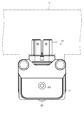
- FIG. 1 is a perspective view showing a state in which the shield connector according to the embodiment is attached to the case of the device.
- FIG. 2 is a plan view of the shield connector according to the embodiment.
- FIG. 3 is a front view of the shield connector according to the embodiment.
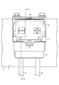
- FIG. 4 is a sectional view taken along line 4-4 in FIG.
- FIG. 5 is an explanatory diagram for explaining the high radiation portion of the shield connector in the embodiment.
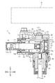
- FIG. 6 is a cross-sectional view of the shield connector in the modified example.
- the shielded connector of the present disclosure is [1] A housing, a shield shell that covers the outside of the housing, a terminal housed in the housing and electrically connected to a device on the other side, and an internal conductor that electrically connects the terminal and an electric wire. At least a part of the surface of the housing, the surface of the shield shell, the surface of the terminal, and the surface of the inner conductor is provided with a high radiation portion having a radiation rate higher than that of the core wire of the electric wire. Be prepared.
- heat generated in the terminal and the internal conductor due to energization can be positively dissipated from the housing and the shield shell, so that the size is large.
- the heat dissipation can be improved without making it.
- the shield shell preferably includes a low emissivity portion having a lower emissivity than the high emissivity portion on at least a part of the outer surface of the shield shell.
- the outer surface of the shield shell is provided with a low radiant portion having a lower emissivity than the high radiant portion, for example, when a heat source is present outside, the heat generated by the heat source in the low radiant portion The effect can be suppressed.
- the low radiant portion is provided at a position on the outer surface of the shield shell facing an external heat source.
- the low radiant portion at a position facing the external heat source inside the outer surface of the shield shell, the influence of heat by the external heat source can be suppressed.
- the shield connector 10 of the present embodiment is attached to the housing C of a device such as an inverter or a motor of a hybrid vehicle or an electric vehicle, for example.
- a device-side connector (not shown) is provided inside the housing C.
- the shield connector 10 can be fitted to the device-side connector.
- the vertical direction will be described with reference to the vertical direction of FIG. Regarding the front-rear direction, the left-right direction in FIG. 4 is used as a reference, the left side in the figure (fitting direction with the device-side connector) is the front, and the right side in the figure (disengagement direction with the device-side connector). Described as backward.
- the shield connector 10 includes a housing 11 made of synthetic resin, a shield shell 12 covering the housing 11, an internal conductive member 13 provided inside the housing 11, and an internal conductive member 13. It has a connection terminal 14 that electrically connects the terminal and the terminal of the connector on the other side.
- the housing 11 is made of, for example, synthetic resin, and is configured to form a substantially L shape as a whole. One end of the housing 11 protrudes forward and the other end protrudes downward.
- the device-side connector is connected to the front end of the housing 11, and the terminal of the electric wire W is introduced to the lower end of the housing 11. In other words, the electric wire W is pulled out from below the housing 11.
- the housing 11 has a rear member 21, a front member 22, and a cover member 23.
- the rear member 21 has a first tubular portion 24 extending in the front-rear direction and a second tubular portion 25 extending downward from the rear side of the first tubular portion 24 so as to form a substantially L shape. ..
- the first tubular portion 24 has openings 24a and 24b at both ends in the front-rear direction.
- a cover member 23 is detachably provided in the opening 24a on the rear side of the first tubular portion 24.
- a front member 22 is attached to the opening 24b on the front side of the first tubular portion 24.
- the front member 22 is configured to have a tubular shape, for example.
- the internal conductive member 13 connects the first conductive member 31 connected to the core wire W1 of the electric wire W, the second conductive member 32 connected to the first conductive member 31, the second conductive member 32, and the connection terminal 14. It has a third conductive member 33 to be formed.
- the first conductive member 31 has a barrel portion 31a to which the core wire W1 of the electric wire W is connected and a terminal portion 31b through which the fixing screw N1 is inserted.
- the first conductive member 31 of the present embodiment has a configuration in which the barrel portion 31a and the terminal portion 31b are arranged side by side in the vertical direction.
- the barrel portion 31a of the first conductive member 31 and the core wire W1 of the electric wire W are housed in the second tubular portion 25. Further, the terminal portion 31b of the first conductive member 31 is housed in the first tubular portion 24.
- the core wire W1 of the electric wire W and the barrel portion 31a can be connected by, for example, crimping or welding, but the connection is not limited to this, and a known connection method may be used for connection.
- the second conductive member 32 is connected to the upper end portion of the first conductive member 31 extending in the vertical direction and is connected to the rear end portion of the third conductive member 33 extending in the front-rear direction. That is, the second conductive member 32 relays between the first conductive member 31 and the third conductive member 33 whose extending directions are orthogonal to each other, and for example, a substantially L-shaped plate-shaped conductive member can be adopted.
- the second conductive member 32 of the embodiment of this example is fastened together with the terminal portion 31b of the first conductive member 31 by the fixing screw N1.
- the fixing screw N1 is fastened together with the terminal portion 31b of the first conductive member 31 by the fixing screw N1.
- the third conductive member 33 is a flexible conductive member.
- a braided wire can be adopted as an example, but the present invention is not limited to this.
- the third conductive member 33 is provided substantially closer to the front of the first tubular portion 24 of the rear member 21 of the housing 11.
- connection terminal 14 is a conductive member attached to the front end of the third conductive member 33.
- the connection terminal 14 has, for example, a square cylinder portion having an elastic contact piece elastically in contact with the standby terminal of the device, and a barrel portion connected to the third conductive member 33 by crimping or welding. It is configured to be arranged side by side in the direction.
- the connection terminal 14 is housed in a storage space inside the front member 22 of the housing 11.
- the housing 11 of the present embodiment is covered with a shield shell 12 made of a conductive metal material.
- the shield shell 12 is configured by assembling the lower member 41 and the upper member 42 to each other.
- the lower member 41 is formed by pressing a metal plate material such as aluminum or an aluminum alloy
- the upper member 42 is made of a metal such as aluminum or an aluminum alloy and is formed by die casting.
- the lower member 41 and the upper member 42 are fixed to the housing 11 by co-tightening with fixing screws N2.
- the upper member 42 is fixed to the housing 11 by the fixing screw N3.
- the shield connector 10 of the present embodiment has a high radiation portion 51 on the surface 14a of the connection terminal 14, the surface 13a of the internal conductive member 13, the surface 11a of the housing 11, and the inner surface 12a of the shield shell 12.
- the high radiation unit 51 has an emissivity higher than that of, for example, the core wire W1 (copper) of the electric wire W.
- the core wire W1 made of copper has a high emissivity when it is oxidized, for example, but the emissivity here refers to the emissivity before oxidation.
- the emissivity of the high radiation unit 51 is preferably 0.7 or more, for example.
- the emissivity of the high radiation unit 51 may be the same as a whole, or the emissivity may be different.
- the high radiation portion 51 of the connection terminal 14, the high radiation portion 51 of the internal conductive member 13, and the high radiation portion 51 of the shield shell 12 can be formed by, for example, a plating treatment or a painting treatment. Further, the high radiation portion 51 of the housing 11 may be formed by using, for example, a pre-colored resin material, or may be formed by painting or the like on the surface 11a of the housing 11.
- the outer surface 12b of the shield shell 12 has a low emissivity portion 52 having a lower emissivity than the high emissivity portion 51 as a whole.
- the low radiation portion 52 is, for example, the outer surface 12b itself of the shield shell 12. That is, the emissivity of the low emissivity portion 52 is the emissivity of the outer surface 12b of the shield shell 12.
- the shield shell 12 is made of a conductive metal material (aluminum, an aluminum alloy, etc., for example), and the emissivity in this case is, for example, 0.3 or less.
- the emissivity of the low emissivity unit 52 may be the same as a whole, or the emissivity may be different.
- the core wire W1 of the electric wire W is connected to the internal conductive member 13, and the internal conductive member 13 is connected to the connection terminal 14. Then, the connection terminal 14 is connected to, for example, the terminal of the device-side connector of the other device. As a result, current can be supplied between the electric wire W (core wire W1) and the mating device.
- a high emissivity portion having a higher emissivity than the core wire W1 of the electric wire W on the surface 14a of the connection terminal 14, the surface 13a of the internal conductive member 13, the surface 11a of the housing 11, and the inner surface 12a of the shield shell 12 Has 51.
- the shield connector 10 when a current is supplied between the device side connector and the electric wire W, heat is generated in, for example, the internal conductive member 13 and the connection terminal 14 connecting between the mating side connector and the electric wire W. To do. A part of the heat generated in the internal conductive member 13 and the connection terminal 14 is transferred to the housing 11 having the high radiation portion 51 via the air layer.
- At least a part of the heat transferred to the housing 11 is transferred to the shield shell 12 having the high radiation portion 51.
- the heat transferred to the shield shell 12 is dissipated to the outside.
- the outer surface 12b of the shield shell 12 has the low radiation portion 52, it is suppressed that the heat radiated is transferred to the inside from the outer surface 12b of the shield shell 12 again.
- the low radiation portion 52 is provided on the outer surface 12b of the shield shell 12, the influence of heat by the external heat source can be suppressed.
- the low radiant portion 52 Since at least a part of the outer surface 12b of the shield shell 12 is provided with a low radiant portion 52 having a lower emissivity than the high radiant portion 51, for example, when a heat source exists outside, the low radiant portion 52 receives heat from the heat source.
- the influence of can be suppressed.
- the motor or the inverter itself tends to be an external heat source, and the influence thereof is large. Therefore, a configuration in which the low radiation portion 52 is provided on the outer surface 12b of the shield shell 12 located on the outermost side can suitably suppress the influence of heat from the heat source.
- a configuration having a low radiation portion 52 on a part of the outer surface 12b may be adopted.
- the high radiation portion 51 is provided in the remaining part of the outer surface 12b.
- a configuration may be adopted in which the low radiation portion 52 is provided at the portion 12c of the outer surface 12b facing the external heat source H.
- the influence of heat by the external heat source H can be effectively suppressed.
- the shield connector 10 is often close to the vehicle drive source (motor) or the inverter, it is easily affected by heat from the heat source H, and the configuration provided with the low radiation portion as described above is affected by the heat from the heat source H. It can be suppressed suitably.
- a portion of the outer surface 12b that does not face the external heat source H may have a high radiation portion 51.
- the low radiation portion 52 may be omitted, and a configuration having the high radiation portion 51 on the outer surface 12b of the shield shell 12 may be adopted. That is, a configuration having a high radiation portion 51 on the inner surface 12a and the outer surface 12b of the shield shell 12 may be adopted.
- the housing 11 is composed of the rear member 21, the front member 22, and the cover member 23, but the present invention is not limited to this.
- a configuration in which the rear member 21 and the front member 22 are integrally formed in advance may be adopted.
- the housing 11 may have a configuration of two or less members or a configuration of four or more members.
- the shield shell 12 is composed of the lower member 41 and the upper member 42, but the present invention is not limited to this.
- a configuration in which the lower member and the upper member are integrally formed in advance may be adopted.
- the shield shell 12 may be composed of three or more members.
- the shield shell 12 is formed by fastening the lower member 41 and the upper member 42 together, but the shield shell is formed by separately screwing the upper member and the lower member to the housing 11. May be configured.
- the L-shaped housing 11 in which the electric wire W is pulled out downward is adopted, but the present invention is not limited to this.
- an I-shaped (straight line) housing in which the electric wire W is pulled out rearward may be used.
- the internal conductive member 13 that connects the electric wire W and the connection terminal 14 is composed of three members, a first conductive member 31, a second conductive member 32, and a third conductive member 33. , Not limited to this.
- the number of internal conductive members that connect the electric wire W and the connection terminal 14 can be changed as appropriate.
- the housing 11, the internal conductive member 13, and the housing 11 and the connection terminal 14 may face each other via an air layer.
- the high radiation portion 51 is the base material of the housing 11 (for example, synthetic resin), the base material of the shield shell 12 (for example, conductive metal), and the base material of the connection terminal 14 (for example, conductive). It is configured to adhere to the base material (for example, conductive metal) of the internal conductive member 13 (for example) and increase the emissivity of the base material with respect to infrared rays (for example, near infrared rays and far infrared rays) having at least a predetermined wavelength. It may be an emissivity improving film.
- some or all of the plurality of high radiation portions 51 are formed with the base material or base material of the housing 11, the shield shell 12, the connection terminal 14, and the internal conductive member 13. It can be made of the same or different materials.
- the base material of the shield shell 12, the base material of the connection terminal 14, and the base material of the internal conductive member 13 contain a first metal element (for example, aluminum) as a main component.
- the high radiation portion 51 which can be formed by the metal base material of 1, may be a plating film containing a second metal element (for example, nickel, chromium, etc.) different from the first metal element. It may be a resin film and may contain a dye or a colorant.
- a shielded connector includes a housing, a shield shell covering the outside of the housing, terminals housed in the housing and electrically connected to a counterpart device, and the terminals and electric wires.
- Shield connector 11 Housing 11a Surface 12 Shield shell 12a Inner surface 12b Outer surface 12c Part 13 Internal conductive member (inner conductor) 13a Surface 14 Connection terminal (terminal) 14a Surface 21 Rear member 22 Front member 23 Cover member 24 1st tubular part 24a Opening 24b Opening 25 2nd tubular part 31 1st conductive member 31a Barrel part 31b Terminal part 32 2nd conductive member 33 3rd conductive member 41 Lower Member 42 Upper member 51 High radiation part 52 Low radiation part C Housing H Heat source N1 Fixing screw N2 Fixing screw N3 Fixing screw W Electric wire W1 Core wire
Landscapes
- Details Of Connecting Devices For Male And Female Coupling (AREA)
- Connector Housings Or Holding Contact Members (AREA)
Priority Applications (2)
| Application Number | Priority Date | Filing Date | Title |
|---|---|---|---|
| US17/614,005 US11942729B2 (en) | 2019-06-06 | 2020-05-28 | Shield connector |
| CN202080040677.1A CN113906638B (zh) | 2019-06-06 | 2020-05-28 | 屏蔽连接器 |
Applications Claiming Priority (2)
| Application Number | Priority Date | Filing Date | Title |
|---|---|---|---|
| JP2019-106451 | 2019-06-06 | ||
| JP2019106451A JP2020202036A (ja) | 2019-06-06 | 2019-06-06 | シールドコネクタ |
Publications (1)
| Publication Number | Publication Date |
|---|---|
| WO2020246352A1 true WO2020246352A1 (ja) | 2020-12-10 |
Family
ID=73652516
Family Applications (1)
| Application Number | Title | Priority Date | Filing Date |
|---|---|---|---|
| PCT/JP2020/021028 Ceased WO2020246352A1 (ja) | 2019-06-06 | 2020-05-28 | シールドコネクタ |
Country Status (4)
| Country | Link |
|---|---|
| US (1) | US11942729B2 (enExample) |
| JP (1) | JP2020202036A (enExample) |
| CN (1) | CN113906638B (enExample) |
| WO (1) | WO2020246352A1 (enExample) |
Cited By (1)
| Publication number | Priority date | Publication date | Assignee | Title |
|---|---|---|---|---|
| US20240154366A1 (en) * | 2021-03-08 | 2024-05-09 | Autonetworks Technologies, Ltd. | Connector |
Families Citing this family (6)
| Publication number | Priority date | Publication date | Assignee | Title |
|---|---|---|---|---|
| JP2020202036A (ja) * | 2019-06-06 | 2020-12-17 | 株式会社オートネットワーク技術研究所 | シールドコネクタ |
| US12407028B2 (en) | 2021-02-19 | 2025-09-02 | Lg Energy Solution, Ltd. | Electrode assembly, battery, and battery pack and vehicle including the same |
| US12401160B2 (en) * | 2022-03-09 | 2025-08-26 | Tyco Electronics (Shanghai) Co., Ltd. | Connector and connector assembly |
| DE102022129113A1 (de) * | 2022-11-03 | 2024-05-08 | Te Connectivity Germany Gmbh | Geschirmter elektrischer Aggregatverbinder für ein Aggregat eines Fahrzeugs |
| DE102023134836A1 (de) * | 2023-12-12 | 2025-06-12 | Lisa Dräxlmaier GmbH | Konfektionierte leitung und verfahren zum konfektionieren einer leitung |
| WO2025187287A1 (ja) * | 2024-03-08 | 2025-09-12 | 矢崎総業株式会社 | コネクタ |
Citations (5)
| Publication number | Priority date | Publication date | Assignee | Title |
|---|---|---|---|---|
| JP2015082464A (ja) * | 2013-10-24 | 2015-04-27 | 住友電装株式会社 | シールドコネクタ |
| JP2015122250A (ja) * | 2013-12-25 | 2015-07-02 | 株式会社オートネットワーク技術研究所 | 導電部材 |
| JP2015204402A (ja) * | 2014-04-15 | 2015-11-16 | 株式会社オートネットワーク技術研究所 | 電磁シールド部材 |
| JP2015220030A (ja) * | 2014-05-15 | 2015-12-07 | 株式会社オートネットワーク技術研究所 | 接続装置 |
| JP2017098418A (ja) * | 2015-11-25 | 2017-06-01 | 株式会社オートネットワーク技術研究所 | 回路構成体、電気接続箱及び回路構成体の製造方法 |
Family Cites Families (44)
| Publication number | Priority date | Publication date | Assignee | Title |
|---|---|---|---|---|
| US5541448A (en) * | 1991-10-16 | 1996-07-30 | Texas Instruments Inc. | Electronic circuit card |
| US5295843A (en) * | 1993-01-19 | 1994-03-22 | The Whitaker Corporation | Electrical connector for power and signal contacts |
| JP2002313453A (ja) * | 2001-04-18 | 2002-10-25 | Yazaki Corp | 機器直付け用シールドコネクタ |
| CN2687897Y (zh) * | 2004-01-06 | 2005-03-23 | 富士康(昆山)电脑接插件有限公司 | 电连接器 |
| JP4498163B2 (ja) * | 2005-02-08 | 2010-07-07 | 株式会社東芝 | 電子機器の放熱装置 |
| US20060185878A1 (en) * | 2005-02-18 | 2006-08-24 | Aviv Soffer | Wall mounted housing for insertable computing apparatus |
| US20070117458A1 (en) * | 2005-11-18 | 2007-05-24 | Picolight Incorporated | Pluggable module and cage |
| CN201029172Y (zh) * | 2006-11-24 | 2008-02-27 | 富士康(昆山)电脑接插件有限公司 | 电子卡连接器组合 |
| JP2011048949A (ja) * | 2009-08-25 | 2011-03-10 | Sumitomo Wiring Syst Ltd | シールドコネクタ装置 |
| JP5555536B2 (ja) * | 2010-04-28 | 2014-07-23 | 矢崎総業株式会社 | コネクタ |
| JP4905586B1 (ja) * | 2010-12-21 | 2012-03-28 | 日立電線株式会社 | コネクタ |
| JP5589858B2 (ja) * | 2011-01-14 | 2014-09-17 | 日立金属株式会社 | コネクタ |
| JP5673457B2 (ja) * | 2011-01-19 | 2015-02-18 | 日立金属株式会社 | コネクタ |
| JP5727839B2 (ja) * | 2011-03-31 | 2015-06-03 | 矢崎総業株式会社 | シールドコネクタ |
| JP5281121B2 (ja) * | 2011-06-14 | 2013-09-04 | 三菱電機株式会社 | 車載電子装置の基板収納筐体 |
| JP5733573B2 (ja) * | 2011-09-05 | 2015-06-10 | 住友電装株式会社 | 機器用コネクタ |
| JP2014086349A (ja) * | 2012-10-25 | 2014-05-12 | Sumitomo Wiring Syst Ltd | コネクタ |
| US9306312B2 (en) * | 2012-10-29 | 2016-04-05 | Carlisle Interconnect Technologies, Inc. | High density sealed electrical connector with multiple shielding strain relief devices |
| CN104756325B (zh) * | 2012-10-30 | 2017-04-12 | 矢崎总业株式会社 | 连接器 |
| JP5790624B2 (ja) * | 2012-11-07 | 2015-10-07 | 住友電装株式会社 | 機器用コネクタ |
| JP5817709B2 (ja) * | 2012-11-28 | 2015-11-18 | 住友電装株式会社 | 機器用コネクタ |
| US20140153192A1 (en) * | 2012-12-05 | 2014-06-05 | Molex Incorporated | Module cage with integrated emi aspect |
| JP5969405B2 (ja) * | 2013-01-30 | 2016-08-17 | 日立オートモティブシステムズ株式会社 | 車載用電子モジュール |
| WO2015060113A1 (ja) | 2013-10-24 | 2015-04-30 | 住友電装株式会社 | シールドコネクタ |
| US9425562B2 (en) * | 2014-03-24 | 2016-08-23 | Tyco Electronics Corporation | Cable connector having a shielding insert |
| CN107112682B (zh) * | 2014-10-08 | 2019-10-08 | 株式会社自动网络技术研究所 | 连接器 |
| JP6132868B2 (ja) * | 2015-03-31 | 2017-05-24 | 矢崎総業株式会社 | コネクタ |
| CN104868282B (zh) * | 2015-05-07 | 2024-09-03 | 连展科技(深圳)有限公司 | 插座电连接器 |
| JP6460404B2 (ja) * | 2015-05-20 | 2019-01-30 | 株式会社オートネットワーク技術研究所 | レバー式コネクタ |
| US10231348B2 (en) * | 2015-05-28 | 2019-03-12 | Yazaki Corporation | Heat dissipation structure for connector module |
| JP6364434B2 (ja) * | 2016-03-01 | 2018-07-25 | 矢崎総業株式会社 | シールドコネクタの固定構造 |
| JP6610954B2 (ja) * | 2016-06-01 | 2019-11-27 | 住友電装株式会社 | シールドコネクタ |
| JP6614051B2 (ja) * | 2016-07-12 | 2019-12-04 | 株式会社オートネットワーク技術研究所 | 電気接続アセンブリの製造方法 |
| JP2018113119A (ja) * | 2017-01-10 | 2018-07-19 | 住友電装株式会社 | シールドコネクタおよびシールドコネクタの製造方法 |
| DE102017204939A1 (de) * | 2017-03-23 | 2018-09-27 | Te Connectivity Germany Gmbh | Elektrischer Verbinder und elektrische Verbindungsanordnung umfassend einen elektrischen Verbinder |
| US10468839B2 (en) * | 2017-06-29 | 2019-11-05 | Lotes Co., Ltd | Assembly having thermal conduction members |
| CN207082649U (zh) * | 2017-07-14 | 2018-03-09 | 番禺得意精密电子工业有限公司 | 连接器组合 |
| CN207098137U (zh) * | 2017-07-14 | 2018-03-13 | 番禺得意精密电子工业有限公司 | 连接器组合 |
| JP6611368B2 (ja) * | 2017-07-28 | 2019-11-27 | 矢崎総業株式会社 | コネクタ |
| US10768054B2 (en) * | 2017-11-29 | 2020-09-08 | Te Connectivity Corporation | Temperature sensing electrical device |
| JP6926998B2 (ja) * | 2017-12-05 | 2021-08-25 | トヨタ自動車株式会社 | 電気機器の車載構造 |
| JP6811229B2 (ja) * | 2018-12-28 | 2021-01-13 | 矢崎総業株式会社 | コネクタ |
| JP7183802B2 (ja) * | 2019-01-11 | 2022-12-06 | 株式会社オートネットワーク技術研究所 | コネクタ |
| JP2020202036A (ja) * | 2019-06-06 | 2020-12-17 | 株式会社オートネットワーク技術研究所 | シールドコネクタ |
-
2019
- 2019-06-06 JP JP2019106451A patent/JP2020202036A/ja active Pending
-
2020
- 2020-05-28 US US17/614,005 patent/US11942729B2/en active Active
- 2020-05-28 CN CN202080040677.1A patent/CN113906638B/zh active Active
- 2020-05-28 WO PCT/JP2020/021028 patent/WO2020246352A1/ja not_active Ceased
Patent Citations (5)
| Publication number | Priority date | Publication date | Assignee | Title |
|---|---|---|---|---|
| JP2015082464A (ja) * | 2013-10-24 | 2015-04-27 | 住友電装株式会社 | シールドコネクタ |
| JP2015122250A (ja) * | 2013-12-25 | 2015-07-02 | 株式会社オートネットワーク技術研究所 | 導電部材 |
| JP2015204402A (ja) * | 2014-04-15 | 2015-11-16 | 株式会社オートネットワーク技術研究所 | 電磁シールド部材 |
| JP2015220030A (ja) * | 2014-05-15 | 2015-12-07 | 株式会社オートネットワーク技術研究所 | 接続装置 |
| JP2017098418A (ja) * | 2015-11-25 | 2017-06-01 | 株式会社オートネットワーク技術研究所 | 回路構成体、電気接続箱及び回路構成体の製造方法 |
Cited By (1)
| Publication number | Priority date | Publication date | Assignee | Title |
|---|---|---|---|---|
| US20240154366A1 (en) * | 2021-03-08 | 2024-05-09 | Autonetworks Technologies, Ltd. | Connector |
Also Published As
| Publication number | Publication date |
|---|---|
| JP2020202036A (ja) | 2020-12-17 |
| CN113906638A (zh) | 2022-01-07 |
| US11942729B2 (en) | 2024-03-26 |
| US20220224059A1 (en) | 2022-07-14 |
| CN113906638B (zh) | 2024-05-28 |
Similar Documents
| Publication | Publication Date | Title |
|---|---|---|
| WO2020246352A1 (ja) | シールドコネクタ | |
| JP4955754B2 (ja) | シールドシェル | |
| US9472893B1 (en) | Connector | |
| JP5741560B2 (ja) | 機器用コネクタ | |
| KR101555115B1 (ko) | 실드 커넥터 | |
| CN107112682B (zh) | 连接器 | |
| JP2014107151A (ja) | 機器用コネクタ | |
| JP2009252682A (ja) | コネクタ | |
| WO2018131410A1 (ja) | シールドコネクタおよびシールドコネクタの製造方法 | |
| WO2020179245A1 (ja) | 外装部材及びワイヤハーネス | |
| WO2014061727A1 (ja) | シールドコネクタ | |
| JP2023004753A (ja) | コネクタ | |
| JP6334359B2 (ja) | シールドコネクタの固定構造 | |
| WO2021024781A1 (ja) | ワイヤハーネス | |
| US10770200B2 (en) | Shielded conductive path | |
| JP5170013B2 (ja) | シールドコネクタ | |
| JP5776665B2 (ja) | シールドコネクタ | |
| JP5781289B2 (ja) | ワイヤハーネス配索構造 | |
| JP2017062922A (ja) | コネクタ | |
| JP2010187474A (ja) | 電線保護管 | |
| JP2007103044A (ja) | シールドコネクタ | |
| JP3908924B2 (ja) | 機器用シールドコネクタ | |
| CN102394419B (zh) | 连接器 | |
| JP2021190345A (ja) | シールドコネクタ | |
| JP6807025B2 (ja) | コネクタ |
Legal Events
| Date | Code | Title | Description |
|---|---|---|---|
| 121 | Ep: the epo has been informed by wipo that ep was designated in this application |
Ref document number: 20817198 Country of ref document: EP Kind code of ref document: A1 |
|
| NENP | Non-entry into the national phase |
Ref country code: DE |
|
| 122 | Ep: pct application non-entry in european phase |
Ref document number: 20817198 Country of ref document: EP Kind code of ref document: A1 |