WO2020246352A1 - Shield connector - Google Patents
Shield connector Download PDFInfo
- Publication number
- WO2020246352A1 WO2020246352A1 PCT/JP2020/021028 JP2020021028W WO2020246352A1 WO 2020246352 A1 WO2020246352 A1 WO 2020246352A1 JP 2020021028 W JP2020021028 W JP 2020021028W WO 2020246352 A1 WO2020246352 A1 WO 2020246352A1
- Authority
- WO
- WIPO (PCT)
- Prior art keywords
- housing
- conductive member
- shield shell
- emissivity
- shield
- Prior art date
Links
Images


Classifications
-
- H—ELECTRICITY
- H01—ELECTRIC ELEMENTS
- H01R—ELECTRICALLY-CONDUCTIVE CONNECTIONS; STRUCTURAL ASSOCIATIONS OF A PLURALITY OF MUTUALLY-INSULATED ELECTRICAL CONNECTING ELEMENTS; COUPLING DEVICES; CURRENT COLLECTORS
- H01R13/00—Details of coupling devices of the kinds covered by groups H01R12/70 or H01R24/00 - H01R33/00
- H01R13/648—Protective earth or shield arrangements on coupling devices, e.g. anti-static shielding
- H01R13/658—High frequency shielding arrangements, e.g. against EMI [Electro-Magnetic Interference] or EMP [Electro-Magnetic Pulse]
- H01R13/6581—Shield structure
- H01R13/6582—Shield structure with resilient means for engaging mating connector
-
- H—ELECTRICITY
- H01—ELECTRIC ELEMENTS
- H01R—ELECTRICALLY-CONDUCTIVE CONNECTIONS; STRUCTURAL ASSOCIATIONS OF A PLURALITY OF MUTUALLY-INSULATED ELECTRICAL CONNECTING ELEMENTS; COUPLING DEVICES; CURRENT COLLECTORS
- H01R13/00—Details of coupling devices of the kinds covered by groups H01R12/70 or H01R24/00 - H01R33/00
- H01R13/46—Bases; Cases
- H01R13/533—Bases, cases made for use in extreme conditions, e.g. high temperature, radiation, vibration, corrosive environment, pressure
-
- H—ELECTRICITY
- H01—ELECTRIC ELEMENTS
- H01R—ELECTRICALLY-CONDUCTIVE CONNECTIONS; STRUCTURAL ASSOCIATIONS OF A PLURALITY OF MUTUALLY-INSULATED ELECTRICAL CONNECTING ELEMENTS; COUPLING DEVICES; CURRENT COLLECTORS
- H01R13/00—Details of coupling devices of the kinds covered by groups H01R12/70 or H01R24/00 - H01R33/00
- H01R13/02—Contact members
-
- H—ELECTRICITY
- H01—ELECTRIC ELEMENTS
- H01R—ELECTRICALLY-CONDUCTIVE CONNECTIONS; STRUCTURAL ASSOCIATIONS OF A PLURALITY OF MUTUALLY-INSULATED ELECTRICAL CONNECTING ELEMENTS; COUPLING DEVICES; CURRENT COLLECTORS
- H01R13/00—Details of coupling devices of the kinds covered by groups H01R12/70 or H01R24/00 - H01R33/00
- H01R13/46—Bases; Cases
- H01R13/502—Bases; Cases composed of different pieces
-
- H—ELECTRICITY
- H01—ELECTRIC ELEMENTS
- H01R—ELECTRICALLY-CONDUCTIVE CONNECTIONS; STRUCTURAL ASSOCIATIONS OF A PLURALITY OF MUTUALLY-INSULATED ELECTRICAL CONNECTING ELEMENTS; COUPLING DEVICES; CURRENT COLLECTORS
- H01R13/00—Details of coupling devices of the kinds covered by groups H01R12/70 or H01R24/00 - H01R33/00
- H01R13/46—Bases; Cases
- H01R13/516—Means for holding or embracing insulating body, e.g. casing, hoods
-
- H—ELECTRICITY
- H01—ELECTRIC ELEMENTS
- H01R—ELECTRICALLY-CONDUCTIVE CONNECTIONS; STRUCTURAL ASSOCIATIONS OF A PLURALITY OF MUTUALLY-INSULATED ELECTRICAL CONNECTING ELEMENTS; COUPLING DEVICES; CURRENT COLLECTORS
- H01R13/00—Details of coupling devices of the kinds covered by groups H01R12/70 or H01R24/00 - H01R33/00
- H01R13/648—Protective earth or shield arrangements on coupling devices, e.g. anti-static shielding
- H01R13/6485—Electrostatic discharge protection
-
- H—ELECTRICITY
- H01—ELECTRIC ELEMENTS
- H01R—ELECTRICALLY-CONDUCTIVE CONNECTIONS; STRUCTURAL ASSOCIATIONS OF A PLURALITY OF MUTUALLY-INSULATED ELECTRICAL CONNECTING ELEMENTS; COUPLING DEVICES; CURRENT COLLECTORS
- H01R2201/00—Connectors or connections adapted for particular applications
- H01R2201/26—Connectors or connections adapted for particular applications for vehicles
Definitions
- the present invention relates to a shielded connector.
- a shield connector As a shield connector, a housing is provided in which a part of the electric wire is held in a state of being inserted, and when the housing is fitted to the mating connector, the core wire of the shielded wire is electrically attached to the terminal of the mating connector. Some are connected (see, for example, Patent Document 1).
- a part of the electric wire is inserted into the housing, and the core wire of the electric wire is electrically connected to the internal conductor and the terminal in the housing.
- the core wire When the terminal of the shield connector comes into contact with the terminal in the mating connector, the core wire is electrically connected to the terminal of the mating connector.
- the heat generated in the terminals and internal conductors in the housing is mainly transferred to the electric wires. Further, since the housing accommodating the terminal and the internal conductor is separated from the terminal and the internal conductor, it is difficult to be transmitted by the internal air layer. Therefore, in the shield connector used for a hybrid vehicle, an electric vehicle, or the like, a large current is also supplied to the connected device, so that the amount of heat generated increases. Therefore, in order to improve the heat dissipation performance, it is necessary to increase the size of the terminals and internal conductors and the diameter of the electric wire, and there is a concern that the shield connector itself will also be increased in size.
- the present invention has been made to solve the above problems, and an object of the present invention is to provide a shielded connector capable of improving heat dissipation performance while suppressing an increase in size.
- the shielded connector of the present disclosure electrically connects a housing, a shield shell covering the outside of the housing, a terminal housed in the housing and electrically connected to a device on the other side, and the terminal and an electric wire. It has an internal conductor to be connected, and at least a part of the surface of the housing, the surface of the shield shell, the surface of the terminal, and the surface of the internal conductor has a radiation coefficient higher than that of the core wire of the electric wire. It has a high radiation unit.
- heat dissipation performance can be improved while suppressing the increase in size.
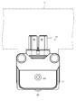
- FIG. 1 is a perspective view showing a state in which the shield connector according to the embodiment is attached to the case of the device.
- FIG. 2 is a plan view of the shield connector according to the embodiment.
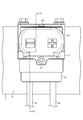
- FIG. 3 is a front view of the shield connector according to the embodiment.
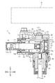
- FIG. 4 is a sectional view taken along line 4-4 in FIG.
- FIG. 5 is an explanatory diagram for explaining the high radiation portion of the shield connector in the embodiment.
- FIG. 6 is a cross-sectional view of the shield connector in the modified example.
- the shielded connector of the present disclosure is [1] A housing, a shield shell that covers the outside of the housing, a terminal housed in the housing and electrically connected to a device on the other side, and an internal conductor that electrically connects the terminal and an electric wire. At least a part of the surface of the housing, the surface of the shield shell, the surface of the terminal, and the surface of the inner conductor is provided with a high radiation portion having a radiation rate higher than that of the core wire of the electric wire. Be prepared.
- heat generated in the terminal and the internal conductor due to energization can be positively dissipated from the housing and the shield shell, so that the size is large.
- the heat dissipation can be improved without making it.
- the shield shell preferably includes a low emissivity portion having a lower emissivity than the high emissivity portion on at least a part of the outer surface of the shield shell.
- the outer surface of the shield shell is provided with a low radiant portion having a lower emissivity than the high radiant portion, for example, when a heat source is present outside, the heat generated by the heat source in the low radiant portion The effect can be suppressed.
- the low radiant portion is provided at a position on the outer surface of the shield shell facing an external heat source.
- the low radiant portion at a position facing the external heat source inside the outer surface of the shield shell, the influence of heat by the external heat source can be suppressed.
- the shield connector 10 of the present embodiment is attached to the housing C of a device such as an inverter or a motor of a hybrid vehicle or an electric vehicle, for example.
- a device-side connector (not shown) is provided inside the housing C.
- the shield connector 10 can be fitted to the device-side connector.
- the vertical direction will be described with reference to the vertical direction of FIG. Regarding the front-rear direction, the left-right direction in FIG. 4 is used as a reference, the left side in the figure (fitting direction with the device-side connector) is the front, and the right side in the figure (disengagement direction with the device-side connector). Described as backward.
- the shield connector 10 includes a housing 11 made of synthetic resin, a shield shell 12 covering the housing 11, an internal conductive member 13 provided inside the housing 11, and an internal conductive member 13. It has a connection terminal 14 that electrically connects the terminal and the terminal of the connector on the other side.
- the housing 11 is made of, for example, synthetic resin, and is configured to form a substantially L shape as a whole. One end of the housing 11 protrudes forward and the other end protrudes downward.
- the device-side connector is connected to the front end of the housing 11, and the terminal of the electric wire W is introduced to the lower end of the housing 11. In other words, the electric wire W is pulled out from below the housing 11.
- the housing 11 has a rear member 21, a front member 22, and a cover member 23.
- the rear member 21 has a first tubular portion 24 extending in the front-rear direction and a second tubular portion 25 extending downward from the rear side of the first tubular portion 24 so as to form a substantially L shape. ..
- the first tubular portion 24 has openings 24a and 24b at both ends in the front-rear direction.
- a cover member 23 is detachably provided in the opening 24a on the rear side of the first tubular portion 24.
- a front member 22 is attached to the opening 24b on the front side of the first tubular portion 24.
- the front member 22 is configured to have a tubular shape, for example.
- the internal conductive member 13 connects the first conductive member 31 connected to the core wire W1 of the electric wire W, the second conductive member 32 connected to the first conductive member 31, the second conductive member 32, and the connection terminal 14. It has a third conductive member 33 to be formed.
- the first conductive member 31 has a barrel portion 31a to which the core wire W1 of the electric wire W is connected and a terminal portion 31b through which the fixing screw N1 is inserted.
- the first conductive member 31 of the present embodiment has a configuration in which the barrel portion 31a and the terminal portion 31b are arranged side by side in the vertical direction.
- the barrel portion 31a of the first conductive member 31 and the core wire W1 of the electric wire W are housed in the second tubular portion 25. Further, the terminal portion 31b of the first conductive member 31 is housed in the first tubular portion 24.
- the core wire W1 of the electric wire W and the barrel portion 31a can be connected by, for example, crimping or welding, but the connection is not limited to this, and a known connection method may be used for connection.
- the second conductive member 32 is connected to the upper end portion of the first conductive member 31 extending in the vertical direction and is connected to the rear end portion of the third conductive member 33 extending in the front-rear direction. That is, the second conductive member 32 relays between the first conductive member 31 and the third conductive member 33 whose extending directions are orthogonal to each other, and for example, a substantially L-shaped plate-shaped conductive member can be adopted.
- the second conductive member 32 of the embodiment of this example is fastened together with the terminal portion 31b of the first conductive member 31 by the fixing screw N1.
- the fixing screw N1 is fastened together with the terminal portion 31b of the first conductive member 31 by the fixing screw N1.
- the third conductive member 33 is a flexible conductive member.
- a braided wire can be adopted as an example, but the present invention is not limited to this.
- the third conductive member 33 is provided substantially closer to the front of the first tubular portion 24 of the rear member 21 of the housing 11.
- connection terminal 14 is a conductive member attached to the front end of the third conductive member 33.
- the connection terminal 14 has, for example, a square cylinder portion having an elastic contact piece elastically in contact with the standby terminal of the device, and a barrel portion connected to the third conductive member 33 by crimping or welding. It is configured to be arranged side by side in the direction.
- the connection terminal 14 is housed in a storage space inside the front member 22 of the housing 11.
- the housing 11 of the present embodiment is covered with a shield shell 12 made of a conductive metal material.
- the shield shell 12 is configured by assembling the lower member 41 and the upper member 42 to each other.
- the lower member 41 is formed by pressing a metal plate material such as aluminum or an aluminum alloy
- the upper member 42 is made of a metal such as aluminum or an aluminum alloy and is formed by die casting.
- the lower member 41 and the upper member 42 are fixed to the housing 11 by co-tightening with fixing screws N2.
- the upper member 42 is fixed to the housing 11 by the fixing screw N3.
- the shield connector 10 of the present embodiment has a high radiation portion 51 on the surface 14a of the connection terminal 14, the surface 13a of the internal conductive member 13, the surface 11a of the housing 11, and the inner surface 12a of the shield shell 12.
- the high radiation unit 51 has an emissivity higher than that of, for example, the core wire W1 (copper) of the electric wire W.
- the core wire W1 made of copper has a high emissivity when it is oxidized, for example, but the emissivity here refers to the emissivity before oxidation.
- the emissivity of the high radiation unit 51 is preferably 0.7 or more, for example.
- the emissivity of the high radiation unit 51 may be the same as a whole, or the emissivity may be different.
- the high radiation portion 51 of the connection terminal 14, the high radiation portion 51 of the internal conductive member 13, and the high radiation portion 51 of the shield shell 12 can be formed by, for example, a plating treatment or a painting treatment. Further, the high radiation portion 51 of the housing 11 may be formed by using, for example, a pre-colored resin material, or may be formed by painting or the like on the surface 11a of the housing 11.
- the outer surface 12b of the shield shell 12 has a low emissivity portion 52 having a lower emissivity than the high emissivity portion 51 as a whole.
- the low radiation portion 52 is, for example, the outer surface 12b itself of the shield shell 12. That is, the emissivity of the low emissivity portion 52 is the emissivity of the outer surface 12b of the shield shell 12.
- the shield shell 12 is made of a conductive metal material (aluminum, an aluminum alloy, etc., for example), and the emissivity in this case is, for example, 0.3 or less.
- the emissivity of the low emissivity unit 52 may be the same as a whole, or the emissivity may be different.
- the core wire W1 of the electric wire W is connected to the internal conductive member 13, and the internal conductive member 13 is connected to the connection terminal 14. Then, the connection terminal 14 is connected to, for example, the terminal of the device-side connector of the other device. As a result, current can be supplied between the electric wire W (core wire W1) and the mating device.
- a high emissivity portion having a higher emissivity than the core wire W1 of the electric wire W on the surface 14a of the connection terminal 14, the surface 13a of the internal conductive member 13, the surface 11a of the housing 11, and the inner surface 12a of the shield shell 12 Has 51.
- the shield connector 10 when a current is supplied between the device side connector and the electric wire W, heat is generated in, for example, the internal conductive member 13 and the connection terminal 14 connecting between the mating side connector and the electric wire W. To do. A part of the heat generated in the internal conductive member 13 and the connection terminal 14 is transferred to the housing 11 having the high radiation portion 51 via the air layer.
- At least a part of the heat transferred to the housing 11 is transferred to the shield shell 12 having the high radiation portion 51.
- the heat transferred to the shield shell 12 is dissipated to the outside.
- the outer surface 12b of the shield shell 12 has the low radiation portion 52, it is suppressed that the heat radiated is transferred to the inside from the outer surface 12b of the shield shell 12 again.
- the low radiation portion 52 is provided on the outer surface 12b of the shield shell 12, the influence of heat by the external heat source can be suppressed.
- the low radiant portion 52 Since at least a part of the outer surface 12b of the shield shell 12 is provided with a low radiant portion 52 having a lower emissivity than the high radiant portion 51, for example, when a heat source exists outside, the low radiant portion 52 receives heat from the heat source.
- the influence of can be suppressed.
- the motor or the inverter itself tends to be an external heat source, and the influence thereof is large. Therefore, a configuration in which the low radiation portion 52 is provided on the outer surface 12b of the shield shell 12 located on the outermost side can suitably suppress the influence of heat from the heat source.
- a configuration having a low radiation portion 52 on a part of the outer surface 12b may be adopted.
- the high radiation portion 51 is provided in the remaining part of the outer surface 12b.
- a configuration may be adopted in which the low radiation portion 52 is provided at the portion 12c of the outer surface 12b facing the external heat source H.
- the influence of heat by the external heat source H can be effectively suppressed.
- the shield connector 10 is often close to the vehicle drive source (motor) or the inverter, it is easily affected by heat from the heat source H, and the configuration provided with the low radiation portion as described above is affected by the heat from the heat source H. It can be suppressed suitably.
- a portion of the outer surface 12b that does not face the external heat source H may have a high radiation portion 51.
- the low radiation portion 52 may be omitted, and a configuration having the high radiation portion 51 on the outer surface 12b of the shield shell 12 may be adopted. That is, a configuration having a high radiation portion 51 on the inner surface 12a and the outer surface 12b of the shield shell 12 may be adopted.
- the housing 11 is composed of the rear member 21, the front member 22, and the cover member 23, but the present invention is not limited to this.
- a configuration in which the rear member 21 and the front member 22 are integrally formed in advance may be adopted.
- the housing 11 may have a configuration of two or less members or a configuration of four or more members.
- the shield shell 12 is composed of the lower member 41 and the upper member 42, but the present invention is not limited to this.
- a configuration in which the lower member and the upper member are integrally formed in advance may be adopted.
- the shield shell 12 may be composed of three or more members.
- the shield shell 12 is formed by fastening the lower member 41 and the upper member 42 together, but the shield shell is formed by separately screwing the upper member and the lower member to the housing 11. May be configured.
- the L-shaped housing 11 in which the electric wire W is pulled out downward is adopted, but the present invention is not limited to this.
- an I-shaped (straight line) housing in which the electric wire W is pulled out rearward may be used.
- the internal conductive member 13 that connects the electric wire W and the connection terminal 14 is composed of three members, a first conductive member 31, a second conductive member 32, and a third conductive member 33. , Not limited to this.
- the number of internal conductive members that connect the electric wire W and the connection terminal 14 can be changed as appropriate.
- the housing 11, the internal conductive member 13, and the housing 11 and the connection terminal 14 may face each other via an air layer.
- the high radiation portion 51 is the base material of the housing 11 (for example, synthetic resin), the base material of the shield shell 12 (for example, conductive metal), and the base material of the connection terminal 14 (for example, conductive). It is configured to adhere to the base material (for example, conductive metal) of the internal conductive member 13 (for example) and increase the emissivity of the base material with respect to infrared rays (for example, near infrared rays and far infrared rays) having at least a predetermined wavelength. It may be an emissivity improving film.
- some or all of the plurality of high radiation portions 51 are formed with the base material or base material of the housing 11, the shield shell 12, the connection terminal 14, and the internal conductive member 13. It can be made of the same or different materials.
- the base material of the shield shell 12, the base material of the connection terminal 14, and the base material of the internal conductive member 13 contain a first metal element (for example, aluminum) as a main component.
- the high radiation portion 51 which can be formed by the metal base material of 1, may be a plating film containing a second metal element (for example, nickel, chromium, etc.) different from the first metal element. It may be a resin film and may contain a dye or a colorant.
- a shielded connector includes a housing, a shield shell covering the outside of the housing, terminals housed in the housing and electrically connected to a counterpart device, and the terminals and electric wires.
- Shield connector 11 Housing 11a Surface 12 Shield shell 12a Inner surface 12b Outer surface 12c Part 13 Internal conductive member (inner conductor) 13a Surface 14 Connection terminal (terminal) 14a Surface 21 Rear member 22 Front member 23 Cover member 24 1st tubular part 24a Opening 24b Opening 25 2nd tubular part 31 1st conductive member 31a Barrel part 31b Terminal part 32 2nd conductive member 33 3rd conductive member 41 Lower Member 42 Upper member 51 High radiation part 52 Low radiation part C Housing H Heat source N1 Fixing screw N2 Fixing screw N3 Fixing screw W Electric wire W1 Core wire
Abstract
The present invention provides a shield connector that can improve heat dissipation performance while suppressing any increase in size. This shield connector 10 has a housing 11, a shield shell 12 that covers the outside of the housing 11, a connecting terminal 14 that is accommodated within the housing 11 and is electrically connected with counterpart-side device, and an internal electrically conductive member 13 that electrically connects the connecting terminal 14 and an electrical wire W. A high-emissivity unit 51 having a higher emissivity than that of at least a core wire W1 of the electrical wire W is provided at least some of a surface 11a of the housing 11, a surface 12a of the shield shell 12, a surface 14a of the connecting terminal 14, and a surface 13a of the internal electrically conductive member 13.
Description
本発明は、シールドコネクタに関する。
The present invention relates to a shielded connector.
従来、シールドコネクタとして、電線の一部が挿入された状態で保持されるハウジングを備え、該ハウジングが相手側コネクタに嵌着されることでシールド電線の芯線が相手側コネクタの端子に電気的に接続されるものがある(例えば、特許文献1参照)。このシールドコネクタは、ハウジング内に電線の一部が挿入され、電線の芯線がハウジング内の内部導体及び端子と電気的に接続されている。シールドコネクタの端子が相手側コネクタ内の端子と接触することで芯線が相手側コネクタの端子に電気的に接続されることとなる。
Conventionally, as a shield connector, a housing is provided in which a part of the electric wire is held in a state of being inserted, and when the housing is fitted to the mating connector, the core wire of the shielded wire is electrically attached to the terminal of the mating connector. Some are connected (see, for example, Patent Document 1). In this shield connector, a part of the electric wire is inserted into the housing, and the core wire of the electric wire is electrically connected to the internal conductor and the terminal in the housing. When the terminal of the shield connector comes into contact with the terminal in the mating connector, the core wire is electrically connected to the terminal of the mating connector.
ところで、上記のようなシールドコネクタでは、ハウジング内の端子や内部導体で発生した熱は主に電線に伝達される。また、端子や内部導体を収容するハウジングに対しては、端子や内部導体と離れているため、内部空気層により伝達され難い。このため、ハイブリッド自動車や電気自動車等に用いるシールドコネクタでは、接続される機器に対しても大電流が供給されるため、発熱量が増加する。そのため、放熱性能を向上させるためには、端子や内部導体の大型化や電線の大径化必要となり、シールドコネクタ自体も大型化することが懸念されている。
By the way, in the shield connector as described above, the heat generated in the terminals and internal conductors in the housing is mainly transferred to the electric wires. Further, since the housing accommodating the terminal and the internal conductor is separated from the terminal and the internal conductor, it is difficult to be transmitted by the internal air layer. Therefore, in the shield connector used for a hybrid vehicle, an electric vehicle, or the like, a large current is also supplied to the connected device, so that the amount of heat generated increases. Therefore, in order to improve the heat dissipation performance, it is necessary to increase the size of the terminals and internal conductors and the diameter of the electric wire, and there is a concern that the shield connector itself will also be increased in size.
本発明は、上記課題を解決するためになされたものであって、その目的は、大型化を抑えつつ放熱性能を向上できるシールドコネクタを提供することにある。
The present invention has been made to solve the above problems, and an object of the present invention is to provide a shielded connector capable of improving heat dissipation performance while suppressing an increase in size.
本開示のシールドコネクタは、ハウジングと、該ハウジングの外側を覆うシールドシェルと、前記ハウジング内に収容されるとともに相手側機器と電気的に接続される端子と、該端子と電線とを電気的に接続する内部導体とを有し、前記ハウジングの表面、前記シールドシェルの表面、前記端子の表面及び前記内部導体の表面の内の少なくとも一部の表面には、少なくとも前記電線の芯線よりも輻射率の高い高輻射部を備える。
The shielded connector of the present disclosure electrically connects a housing, a shield shell covering the outside of the housing, a terminal housed in the housing and electrically connected to a device on the other side, and the terminal and an electric wire. It has an internal conductor to be connected, and at least a part of the surface of the housing, the surface of the shield shell, the surface of the terminal, and the surface of the internal conductor has a radiation coefficient higher than that of the core wire of the electric wire. It has a high radiation unit.
本発明のシールドコネクタによれば、大型化を抑えつつ放熱性能を向上できる。
According to the shield connector of the present invention, heat dissipation performance can be improved while suppressing the increase in size.
[本開示の実施形態の説明]
最初に本開示の実施形態を列記して説明する。 [Explanation of Embodiments of the present disclosure]
First, the embodiments of the present disclosure will be listed and described.
最初に本開示の実施形態を列記して説明する。 [Explanation of Embodiments of the present disclosure]
First, the embodiments of the present disclosure will be listed and described.
本開示のシールドコネクタは、
[1]ハウジングと、該ハウジングの外側を覆うシールドシェルと、前記ハウジング内に収容されるとともに相手側機器と電気的に接続される端子と、該端子と電線とを電気的に接続する内部導体とを有し、前記ハウジングの表面、前記シールドシェルの表面、前記端子の表面及び前記内部導体の表面の内の少なくとも一部には、少なくとも前記電線の芯線よりも輻射率の高い高輻射部を備える。 The shielded connector of the present disclosure is
[1] A housing, a shield shell that covers the outside of the housing, a terminal housed in the housing and electrically connected to a device on the other side, and an internal conductor that electrically connects the terminal and an electric wire. At least a part of the surface of the housing, the surface of the shield shell, the surface of the terminal, and the surface of the inner conductor is provided with a high radiation portion having a radiation rate higher than that of the core wire of the electric wire. Be prepared.
上記態様によれば、電線の芯線よりも輻射率の高い高輻射部を有することで通電に伴う端子や内部導体で発生した熱を積極的にハウジング及びシールドシェルから放熱することができるため、大型化させることなく放熱性を向上できる。
According to the above aspect, by having a high emissivity portion having a higher emissivity than the core wire of the electric wire, heat generated in the terminal and the internal conductor due to energization can be positively dissipated from the housing and the shield shell, so that the size is large. The heat dissipation can be improved without making it.
[2]前記シールドシェルは、前記シールドシェルの外側表面の少なくとも一部に前記高輻射部よりも輻射率が低い低輻射部を備えることが好ましい。
[2] The shield shell preferably includes a low emissivity portion having a lower emissivity than the high emissivity portion on at least a part of the outer surface of the shield shell.
この態様によれば、シールドシェルの外側表面の少なくとも一部に高輻射部よりも輻射率が低い低輻射部を備えるため、例えば外部に熱源が存在する場合に低輻射部において前記熱源による熱の影響を抑えることができる。
According to this aspect, since at least a part of the outer surface of the shield shell is provided with a low radiant portion having a lower emissivity than the high radiant portion, for example, when a heat source is present outside, the heat generated by the heat source in the low radiant portion The effect can be suppressed.
[3]前記低輻射部は、前記シールドシェルの外側表面の内、外部の熱源と対向する位置に設けられることが好ましい。
[3] It is preferable that the low radiant portion is provided at a position on the outer surface of the shield shell facing an external heat source.
この態様によれば、低輻射部をシールドシェルの外側表面の内の外部の熱源と対向する位置に設けることで、外部の熱源による熱の影響を抑えることができる。
According to this aspect, by providing the low radiant portion at a position facing the external heat source inside the outer surface of the shield shell, the influence of heat by the external heat source can be suppressed.
[本開示の実施形態の詳細]
以下、シールドコネクタの具体例を、以下に図面を参照しつつ説明する。なお、本発明はこれらの例示に限定されるものではなく、特許請求の範囲によって示され、特許請求の範囲と均等の意味及び範囲内でのすべての変更が含まれることが意図される。また、図面では、説明の便宜上、構成の一部を誇張又は簡略化して示す場合がある。 [Details of Embodiments of the present disclosure]
Hereinafter, specific examples of the shield connector will be described with reference to the drawings below. It should be noted that the present invention is not limited to these examples, and is indicated by the scope of claims, and is intended to include all modifications within the meaning and scope equivalent to the scope of claims. Further, in the drawings, for convenience of explanation, a part of the configuration may be exaggerated or simplified.
図1~図3に示すように、本実施形態のシールドコネクタ10は、例えば、ハイブリッド自動車や電気自動車等のインバータやモータ等の機器の筐体Cに取り付けられるものである。筐体C内部には、図示しない機器側コネクタが配設されている。シールドコネクタ10は、前記機器側コネクタに嵌合可能とされている。なお、以下の説明において上下方向とは、図4の上下方向を基準として説明する。また、前後方向については、図4の左右方向を基準とし、同図における左方(機器側コネクタとの嵌合方向)を前方とし、同図における右方(機器側コネクタとの離脱方向)を後方として説明する。
As shown in FIGS. 1 to 3, the shield connector 10 of the present embodiment is attached to the housing C of a device such as an inverter or a motor of a hybrid vehicle or an electric vehicle, for example. A device-side connector (not shown) is provided inside the housing C. The shield connector 10 can be fitted to the device-side connector. In the following description, the vertical direction will be described with reference to the vertical direction of FIG. Regarding the front-rear direction, the left-right direction in FIG. 4 is used as a reference, the left side in the figure (fitting direction with the device-side connector) is the front, and the right side in the figure (disengagement direction with the device-side connector). Described as backward.
図1~図4に示すように、シールドコネクタ10は、合成樹脂製のハウジング11と、ハウジング11を覆うシールドシェル12と、ハウジング11の内部に設けられた内部導電部材13と、内部導電部材13と相手側コネクタの端子とを電気的に接続する接続端子14とを有する。
As shown in FIGS. 1 to 4, the shield connector 10 includes a housing 11 made of synthetic resin, a shield shell 12 covering the housing 11, an internal conductive member 13 provided inside the housing 11, and an internal conductive member 13. It has a connection terminal 14 that electrically connects the terminal and the terminal of the connector on the other side.
ハウジング11は例えば合成樹脂製で、全体として略L字状をなすように構成される。ハウジング11の一端が前方に突出するとともに、他端が下方に突出する態様となっている。ハウジング11の前方側の端部に前記機器側コネクタが接続され、ハウジング11の下方側の端部に電線Wの端末が導入されるようになっている。換言すると、電線Wはハウジング11の下方から引き出されている。
The housing 11 is made of, for example, synthetic resin, and is configured to form a substantially L shape as a whole. One end of the housing 11 protrudes forward and the other end protrudes downward. The device-side connector is connected to the front end of the housing 11, and the terminal of the electric wire W is introduced to the lower end of the housing 11. In other words, the electric wire W is pulled out from below the housing 11.
図4に示すように、ハウジング11は、リア部材21とフロント部材22とカバー部材23とを有する。
As shown in FIG. 4, the housing 11 has a rear member 21, a front member 22, and a cover member 23.
リア部材21は、前後方向に延びる第1筒部24と、第1筒部24の後部側から下方に延びる第2筒部25と、を有して略L字状をなすように構成される。
The rear member 21 has a first tubular portion 24 extending in the front-rear direction and a second tubular portion 25 extending downward from the rear side of the first tubular portion 24 so as to form a substantially L shape. ..
第1筒部24は、前後方向両端に開口部24a,24bを有する。第1筒部24の後方側の開口部24aには、カバー部材23が着脱可能に設けられる。第1筒部24の前方側の開口部24bには、フロント部材22が取り付けられる。
The first tubular portion 24 has openings 24a and 24b at both ends in the front-rear direction. A cover member 23 is detachably provided in the opening 24a on the rear side of the first tubular portion 24. A front member 22 is attached to the opening 24b on the front side of the first tubular portion 24.
フロント部材22は、例えば筒状をなすように構成される。
The front member 22 is configured to have a tubular shape, for example.
内部導電部材13は、電線Wの芯線W1と接続される第1導電部材31と、第1導電部材31と接続される第2導電部材32と、第2導電部材32と接続端子14とを接続する第3導電部材33とを有する。
The internal conductive member 13 connects the first conductive member 31 connected to the core wire W1 of the electric wire W, the second conductive member 32 connected to the first conductive member 31, the second conductive member 32, and the connection terminal 14. It has a third conductive member 33 to be formed.
第1導電部材31は、電線Wの芯線W1が接続されるバレル部31aと、固定ねじN1が挿通される端子部31bとを有する。本実施形態の第1導電部材31は、バレル部31aと端子部31bとを上下方向に並べて配置した構成となっている。第1導電部材31のバレル部31a及び電線Wの芯線W1は、第2筒部25内に収容される。また、第1導電部材31の端子部31bは、第1筒部24内に収容される。なお、電線Wの芯線W1とバレル部31aとは、例えば圧着又は溶接による接続が考えられるが、これに限らず、公知の接続方法を用いて接続してもよい。
The first conductive member 31 has a barrel portion 31a to which the core wire W1 of the electric wire W is connected and a terminal portion 31b through which the fixing screw N1 is inserted. The first conductive member 31 of the present embodiment has a configuration in which the barrel portion 31a and the terminal portion 31b are arranged side by side in the vertical direction. The barrel portion 31a of the first conductive member 31 and the core wire W1 of the electric wire W are housed in the second tubular portion 25. Further, the terminal portion 31b of the first conductive member 31 is housed in the first tubular portion 24. The core wire W1 of the electric wire W and the barrel portion 31a can be connected by, for example, crimping or welding, but the connection is not limited to this, and a known connection method may be used for connection.
第2導電部材32は、上下方向に延びる第1導電部材31の上端部に接続されるとともに、前後方向に延びる第3導電部材33の後端部に接続される。すなわち、第2導電部材32は、延出方向が直交する第1導電部材31と第3導電部材33とを中継するものであり、例えば略L字板状の導電部材を採用することができる。本例実施形態の第2導電部材32は、前記固定ねじN1により第1導電部材31の端子部31bと共締めされている。ここで、前述した第1筒部24の後方側の開口部24aからカバー部材23が取り外された状態とすることで開口部24aを用いて固定ねじN1による締結作業が可能となっている。
The second conductive member 32 is connected to the upper end portion of the first conductive member 31 extending in the vertical direction and is connected to the rear end portion of the third conductive member 33 extending in the front-rear direction. That is, the second conductive member 32 relays between the first conductive member 31 and the third conductive member 33 whose extending directions are orthogonal to each other, and for example, a substantially L-shaped plate-shaped conductive member can be adopted. The second conductive member 32 of the embodiment of this example is fastened together with the terminal portion 31b of the first conductive member 31 by the fixing screw N1. Here, by setting the cover member 23 to be removed from the opening 24a on the rear side of the first tubular portion 24 described above, the fastening work with the fixing screw N1 is possible using the opening 24a.
第3導電部材33は、可撓性を有する導電部材である。第3導電部材33は、一例として編組線を採用することができるが、これに限らない。第3導電部材33は、概ねハウジング11のリア部材21の第1筒部24の前方寄りに設けられる。
The third conductive member 33 is a flexible conductive member. As the third conductive member 33, a braided wire can be adopted as an example, but the present invention is not limited to this. The third conductive member 33 is provided substantially closer to the front of the first tubular portion 24 of the rear member 21 of the housing 11.
接続端子14は、第3導電部材33の前端に取り付けられる導電部材である。接続端子14は、例えば機器の待受端子に対して弾性的に接触する弾性接触片を内部に有する角筒部と、第3導電部材33に圧着もしくは溶接によって接続されるバレル部と、を前後方向に並べて配置した構成とされている。接続端子14は、ハウジング11のフロント部材22内の収容空間に収容されている。
The connection terminal 14 is a conductive member attached to the front end of the third conductive member 33. The connection terminal 14 has, for example, a square cylinder portion having an elastic contact piece elastically in contact with the standby terminal of the device, and a barrel portion connected to the third conductive member 33 by crimping or welding. It is configured to be arranged side by side in the direction. The connection terminal 14 is housed in a storage space inside the front member 22 of the housing 11.
図4に示すように、本実施形態のハウジング11は、導電性の金属材からなるシールドシェル12によって覆われている。
As shown in FIG. 4, the housing 11 of the present embodiment is covered with a shield shell 12 made of a conductive metal material.
図1、図3及び図4に示すように、シールドシェル12は、ロア部材41とアッパ部材42とを互いに組み付けることによって構成されている。ロア部材41は、アルミニウムやアルミニウム合金等の金属板材をプレス加工して形成したものであり、アッパ部材42は、アルミニウムやアルミニウム合金等の金属からなり、ダイキャストによって形成したものである。ロア部材41とアッパ部材42とは固定ねじN2によってハウジング11に対して共締めにより固定される。アッパ部材42は、固定ねじN3によってハウジング11に対して固定される。
As shown in FIGS. 1, 3 and 4, the shield shell 12 is configured by assembling the lower member 41 and the upper member 42 to each other. The lower member 41 is formed by pressing a metal plate material such as aluminum or an aluminum alloy, and the upper member 42 is made of a metal such as aluminum or an aluminum alloy and is formed by die casting. The lower member 41 and the upper member 42 are fixed to the housing 11 by co-tightening with fixing screws N2. The upper member 42 is fixed to the housing 11 by the fixing screw N3.
本実施形態のシールドコネクタ10は、接続端子14の表面14aと、内部導電部材13の表面13aと、ハウジング11の表面11aと、シールドシェル12の内側表面12aとに高輻射部51を有する。
The shield connector 10 of the present embodiment has a high radiation portion 51 on the surface 14a of the connection terminal 14, the surface 13a of the internal conductive member 13, the surface 11a of the housing 11, and the inner surface 12a of the shield shell 12.
高輻射部51は、例えば電線Wの芯線W1(銅)の輻射率よりも高い輻射率を有する。例えば銅で構成される芯線W1は、例えば酸化することで輻射率も高くなるが、ここでいう輻射率は酸化前における輻射率を指す。また、高輻射部51の輻射率は、例えば0.7以上であることが好ましい。高輻射部51の輻射率はその全体が同一の輻射率であってもよいし、輻射率が異なっていてもよい。
The high radiation unit 51 has an emissivity higher than that of, for example, the core wire W1 (copper) of the electric wire W. For example, the core wire W1 made of copper has a high emissivity when it is oxidized, for example, but the emissivity here refers to the emissivity before oxidation. Further, the emissivity of the high radiation unit 51 is preferably 0.7 or more, for example. The emissivity of the high radiation unit 51 may be the same as a whole, or the emissivity may be different.
接続端子14の高輻射部51と、内部導電部材13の高輻射部51と、シールドシェル12の高輻射部51とは、例えばメッキ処理や塗装処理により形成する方法を採用することができる。また、ハウジング11の高輻射部51は、例えば予め着色された樹脂材料を用いて形成してもよいし、ハウジング11の表面11aに対して塗装処理等により形成してもよい。
The high radiation portion 51 of the connection terminal 14, the high radiation portion 51 of the internal conductive member 13, and the high radiation portion 51 of the shield shell 12 can be formed by, for example, a plating treatment or a painting treatment. Further, the high radiation portion 51 of the housing 11 may be formed by using, for example, a pre-colored resin material, or may be formed by painting or the like on the surface 11a of the housing 11.
図5に示すように、シールドシェル12の外側表面12bは、その全体に高輻射部51よりも輻射率の低い低輻射部52を有する。低輻射部52は、例えばシールドシェル12の外側表面12bそのものである。すなわち、低輻射部52の輻射率は、シールドシェル12の外側表面12bの輻射率である。シールドシェル12は、前述したように導電性の金属材(一例としてアルミニウムやアルミニウム合金等)で構成されるが、この場合の輻射率は例えば0.3以下である。低輻射部52の輻射率はその全体が同一の輻射率であってもよいし、輻射率が異なっていてもよい。
As shown in FIG. 5, the outer surface 12b of the shield shell 12 has a low emissivity portion 52 having a lower emissivity than the high emissivity portion 51 as a whole. The low radiation portion 52 is, for example, the outer surface 12b itself of the shield shell 12. That is, the emissivity of the low emissivity portion 52 is the emissivity of the outer surface 12b of the shield shell 12. As described above, the shield shell 12 is made of a conductive metal material (aluminum, an aluminum alloy, etc., for example), and the emissivity in this case is, for example, 0.3 or less. The emissivity of the low emissivity unit 52 may be the same as a whole, or the emissivity may be different.
本実施形態の作用を説明する。
The operation of this embodiment will be described.
本実施形態のシールドコネクタ10は、電線Wの芯線W1が内部導電部材13に接続され、内部導電部材13が接続端子14に接続される。そして、接続端子14は、例えば相手機器の機器側コネクタの端子と接続される。これにより、電線W(芯線W1)と相手機器との間において電流供給が可能となっている。
In the shield connector 10 of the present embodiment, the core wire W1 of the electric wire W is connected to the internal conductive member 13, and the internal conductive member 13 is connected to the connection terminal 14. Then, the connection terminal 14 is connected to, for example, the terminal of the device-side connector of the other device. As a result, current can be supplied between the electric wire W (core wire W1) and the mating device.
また、接続端子14の表面14aと、内部導電部材13の表面13aと、ハウジング11の表面11aと、シールドシェル12の内側表面12aとに、電線Wの芯線W1よりも輻射率が高い高輻射部51を有する。ここで、シールドコネクタ10では、機器側コネクタと電線Wとの間において電流が供給される場合、例えば相手側コネクタと電線Wとの間を接続する内部導電部材13及び接続端子14において熱が発生する。内部導電部材13及び接続端子14において発生した熱の一部は、空気層を介して高輻射部51を有するハウジング11に伝達される。ハウジング11に伝達された熱の少なくとも一部は、高輻射部51を有するシールドシェル12に伝達される。シールドシェル12に伝達された熱は、外部に放熱される。このとき、シールドシェル12の外側表面12bは、低輻射部52を有するため、放熱された熱が再度シールドシェル12の外側表面12bから内部に伝達されることが抑えられている。また、外部にその他の熱源が位置する場合であってもシールドシェル12の外側表面12bに低輻射部52を有する構成であるため、外部の熱源による熱の影響を抑えることができる。
Further, a high emissivity portion having a higher emissivity than the core wire W1 of the electric wire W on the surface 14a of the connection terminal 14, the surface 13a of the internal conductive member 13, the surface 11a of the housing 11, and the inner surface 12a of the shield shell 12 Has 51. Here, in the shield connector 10, when a current is supplied between the device side connector and the electric wire W, heat is generated in, for example, the internal conductive member 13 and the connection terminal 14 connecting between the mating side connector and the electric wire W. To do. A part of the heat generated in the internal conductive member 13 and the connection terminal 14 is transferred to the housing 11 having the high radiation portion 51 via the air layer. At least a part of the heat transferred to the housing 11 is transferred to the shield shell 12 having the high radiation portion 51. The heat transferred to the shield shell 12 is dissipated to the outside. At this time, since the outer surface 12b of the shield shell 12 has the low radiation portion 52, it is suppressed that the heat radiated is transferred to the inside from the outer surface 12b of the shield shell 12 again. Further, even when another heat source is located outside, since the low radiation portion 52 is provided on the outer surface 12b of the shield shell 12, the influence of heat by the external heat source can be suppressed.
本実施形態の効果を記載する。
The effect of this embodiment is described.
(1)電線Wの芯線W1よりも輻射率の高い高輻射部51を有することで通電に伴う接続端子14や内部導電部材13で発生した熱を積極的にハウジング11及びシールドシェル12から放熱することができるため、大型化させることなく放熱性を向上できる。
(1) By having a high emissivity portion 51 having a higher emissivity than the core wire W1 of the electric wire W, heat generated in the connection terminal 14 and the internal conductive member 13 due to energization is positively radiated from the housing 11 and the shield shell 12. Therefore, heat dissipation can be improved without increasing the size.
(2)シールドシェル12の外側表面12bの少なくとも一部に高輻射部51よりも輻射率が低い低輻射部52を備えるため、例えば外部に熱源が存在する場合に低輻射部52において熱源による熱の影響を抑えることができる。特に本実施形態のようにモータやインバータを接続するシールドコネクタにおいてはモータやインバータ自身が外部の熱源となりやすく、その影響が大きい。このため、最も外側に位置するシールドシェル12の外側表面12bに低輻射部52を設ける構成は熱源による熱の影響を好適に抑えることができる。
(2) Since at least a part of the outer surface 12b of the shield shell 12 is provided with a low radiant portion 52 having a lower emissivity than the high radiant portion 51, for example, when a heat source exists outside, the low radiant portion 52 receives heat from the heat source. The influence of can be suppressed. In particular, in a shield connector for connecting a motor or an inverter as in the present embodiment, the motor or the inverter itself tends to be an external heat source, and the influence thereof is large. Therefore, a configuration in which the low radiation portion 52 is provided on the outer surface 12b of the shield shell 12 located on the outermost side can suitably suppress the influence of heat from the heat source.
なお、上記実施形態は、以下のように変更して実施することができる。上記実施形態及び以下の変更例は、技術的に矛盾しない範囲で互いに組み合わせて実施することができる。
The above embodiment can be modified and implemented as follows. The above embodiment and the following modified examples can be implemented in combination with each other within a technically consistent range.
・上記実施形態では、シールドシェル12の外側表面12b全体に低輻射部52を有する構成を採用したが、これに限らない。
-In the above embodiment, a configuration having a low radiation portion 52 on the entire outer surface 12b of the shield shell 12 is adopted, but the present invention is not limited to this.
図6に示すように、外側表面12bの一部に低輻射部52を有する構成を採用してもよい。この場合、外側表面12bの内の残りの一部に高輻射部51を有する構成とする。
As shown in FIG. 6, a configuration having a low radiation portion 52 on a part of the outer surface 12b may be adopted. In this case, the high radiation portion 51 is provided in the remaining part of the outer surface 12b.
図6に示すように、外側表面12bにおいて外部の熱源Hと対向する部位12cに低輻射部52を有する構成を採用してもよい。このように、外部の熱源Hと対向する部位12cに低輻射部52を有する構成を採用することで、外部の熱源Hによる熱の影響を効果的に抑制できる。特に、シールドコネクタ10を車両駆動源(モータ)やインバータに近接することが多いため、熱源Hによる熱の影響を受けやすく、前述したような低輻射部を設ける構成は熱源Hによる熱の影響を好適に抑えることができる。図6に示す構成では、外側表面12bにおいて外部の熱源Hと対向していない部位(例えば後面12d)においては、高輻射部51を有する構成としてもよい。
As shown in FIG. 6, a configuration may be adopted in which the low radiation portion 52 is provided at the portion 12c of the outer surface 12b facing the external heat source H. As described above, by adopting the configuration in which the low radiation portion 52 is provided in the portion 12c facing the external heat source H, the influence of heat by the external heat source H can be effectively suppressed. In particular, since the shield connector 10 is often close to the vehicle drive source (motor) or the inverter, it is easily affected by heat from the heat source H, and the configuration provided with the low radiation portion as described above is affected by the heat from the heat source H. It can be suppressed suitably. In the configuration shown in FIG. 6, a portion of the outer surface 12b that does not face the external heat source H (for example, the rear surface 12d) may have a high radiation portion 51.
また、低輻射部52を省略して、シールドシェル12の外側表面12bに高輻射部51を有する構成を採用してもよい。すなわち、シールドシェル12の内側表面12a及び外側表面12bに高輻射部51を有する構成を採用してもよい。
Further, the low radiation portion 52 may be omitted, and a configuration having the high radiation portion 51 on the outer surface 12b of the shield shell 12 may be adopted. That is, a configuration having a high radiation portion 51 on the inner surface 12a and the outer surface 12b of the shield shell 12 may be adopted.
・上記実施形態では、ハウジング11をリア部材21と、フロント部材22、カバー部材23とで構成したが、これに限らない。例えばリア部材21とフロント部材22とを予め一体に形成した構成を採用してもよい。また、ハウジング11を2部材以下の構成や4部材以上の構成としてもよい。
-In the above embodiment, the housing 11 is composed of the rear member 21, the front member 22, and the cover member 23, but the present invention is not limited to this. For example, a configuration in which the rear member 21 and the front member 22 are integrally formed in advance may be adopted. Further, the housing 11 may have a configuration of two or less members or a configuration of four or more members.
・上記実施形態では、シールドシェル12を、ロア部材41とアッパ部材42とで構成したが、これに限らない。例えばロア部材とアッパ部材が予め一体に形成した構成を採用してもよい。シールドシェル12を3部材以上の構成としてもよい。
-In the above embodiment, the shield shell 12 is composed of the lower member 41 and the upper member 42, but the present invention is not limited to this. For example, a configuration in which the lower member and the upper member are integrally formed in advance may be adopted. The shield shell 12 may be composed of three or more members.
・上記実施形態では、ロア部材41とアッパ部材42とを共締めすることによってシールドシェル12を構成しているものの、アッパ部材とロア部材をハウジング11に対して別々にねじ締結することでシールドシェルを構成してもよい。
In the above embodiment, the shield shell 12 is formed by fastening the lower member 41 and the upper member 42 together, but the shield shell is formed by separately screwing the upper member and the lower member to the housing 11. May be configured.
・上記実施形態では、電線Wが下方に引き出されたL字形のハウジング11を採用したが、これに限らない。例えば、電線Wが後方に引き出されたI字形(直線形)のハウジングを用いてもよい。
-In the above embodiment, the L-shaped housing 11 in which the electric wire W is pulled out downward is adopted, but the present invention is not limited to this. For example, an I-shaped (straight line) housing in which the electric wire W is pulled out rearward may be used.
・上記実施形態では、電線Wと接続端子14とを接続する内部導電部材13を、第1導電部材31と、第2導電部材32と、第3導電部材33との3つの部材で構成したが、これに限らない。電線Wと接続端子14との間を接続する内部導電部材の部品数は適宜変更可能である。
In the above embodiment, the internal conductive member 13 that connects the electric wire W and the connection terminal 14 is composed of three members, a first conductive member 31, a second conductive member 32, and a third conductive member 33. , Not limited to this. The number of internal conductive members that connect the electric wire W and the connection terminal 14 can be changed as appropriate.
・ハウジング11と内部導電部材13及びハウジング11と接続端子14は空気層を介して対面してよい。
The housing 11, the internal conductive member 13, and the housing 11 and the connection terminal 14 may face each other via an air layer.
・上記実施形態では特に言及していないが、例えばハウジング11と内部導電部材13との間や、ハウジング11と接続端子14との間に他の部材が配置される場合、この部材についても同様に高輻射部を備える構成を採用してもよい。
-Although not particularly mentioned in the above embodiment, for example, when another member is arranged between the housing 11 and the internal conductive member 13 or between the housing 11 and the connection terminal 14, the same applies to this member. A configuration including a high radiation unit may be adopted.
・本開示のいくつかの実装例では、高輻射部51は、ハウジング11の下地材料(例えば合成樹脂)、シールドシェル12の下地材料(例えば導電性金属)、接続端子14の下地材料(例えば導電性金属)、及び内部導電部材13の下地材料(例えば導電性金属)に密着して、少なくとも所定波長の赤外線(例えば近赤外線、遠赤外線)に対するそれら下地材料の輻射率を増加させるように構成された輻射率向上膜であってよい。
-In some mounting examples of the present disclosure, the high radiation portion 51 is the base material of the housing 11 (for example, synthetic resin), the base material of the shield shell 12 (for example, conductive metal), and the base material of the connection terminal 14 (for example, conductive). It is configured to adhere to the base material (for example, conductive metal) of the internal conductive member 13 (for example) and increase the emissivity of the base material with respect to infrared rays (for example, near infrared rays and far infrared rays) having at least a predetermined wavelength. It may be an emissivity improving film.
・本開示のいくつかの実装例では、複数の高輻射部51のうちの一部または全部は、ハウジング11、シールドシェル12、接続端子14、及び内部導電部材13の各下地材料または母材と同じかまたは異なる材料によって形成されることができる。
In some implementation examples of the present disclosure, some or all of the plurality of high radiation portions 51 are formed with the base material or base material of the housing 11, the shield shell 12, the connection terminal 14, and the internal conductive member 13. It can be made of the same or different materials.
・本開示のいくつかの実装例では、シールドシェル12の下地材料、接続端子14の下地材料、及び内部導電部材13の下地材料は、第1の金属元素(例えばアルミニウム)を主成分として含む第1の金属母材によって形成されることができ、高輻射部51は、前記第1の金属元素とは異なる第2の金属元素(例えば、ニッケル、クロム等)を含むメッキ膜であってよく、樹脂膜であってよく、色素または着色剤を含んでよい。
-In some mounting examples of the present disclosure, the base material of the shield shell 12, the base material of the connection terminal 14, and the base material of the internal conductive member 13 contain a first metal element (for example, aluminum) as a main component. The high radiation portion 51, which can be formed by the metal base material of 1, may be a plating film containing a second metal element (for example, nickel, chromium, etc.) different from the first metal element. It may be a resin film and may contain a dye or a colorant.
[付記1]
本開示の一態様に従うシールドコネクタは、ハウジングと、該ハウジングの外側を覆うシールドシェルと、前記ハウジング内に収容されるとともに相手側機器と電気的に接続される端子と、該端子と電線とを電気的に接続する内部導体とを有し、
前記ハウジングの表面、前記シールドシェルの表面、前記端子の表面及び前記内部導体の表面の内の少なくとも一部には、少なくとも前記電線の芯線を構成する第1材料よりも輻射率の高い第2材料で構成される高輻射部を備える。 [Appendix 1]
A shielded connector according to one aspect of the present disclosure includes a housing, a shield shell covering the outside of the housing, terminals housed in the housing and electrically connected to a counterpart device, and the terminals and electric wires. Has an internal conductor that connects electrically,
At least a part of the surface of the housing, the surface of the shield shell, the surface of the terminal, and the surface of the inner conductor is a second material having a higher emissivity than the first material constituting the core wire of the electric wire. It has a high radiation unit composed of.
10 シールドコネクタ
11 ハウジング
11a 表面
12 シールドシェル
12a 内側表面
12b 外側表面
12c 部位
13 内部導電部材(内部導体)
13a 表面
14 接続端子(端子)
14a 表面
21 リア部材
22 フロント部材
23 カバー部材
24 第1筒部
24a 開口部
24b 開口部
25 第2筒部
31 第1導電部材
31a バレル部
31b 端子部
32 第2導電部材
33 第3導電部材
41 ロア部材
42 アッパ部材
51 高輻射部
52 低輻射部
C 筐体
H 熱源
N1 固定ねじ
N2 固定ねじ
N3 固定ねじ
W 電線
W1 芯線 10Shield connector 11 Housing 11a Surface 12 Shield shell 12a Inner surface 12b Outer surface 12c Part 13 Internal conductive member (inner conductor)
13a Surface 14 Connection terminal (terminal)
14a Surface 21Rear member 22 Front member 23 Cover member 24 1st tubular part 24a Opening 24b Opening 25 2nd tubular part 31 1st conductive member 31a Barrel part 31b Terminal part 32 2nd conductive member 33 3rd conductive member 41 Lower Member 42 Upper member 51 High radiation part 52 Low radiation part C Housing H Heat source N1 Fixing screw N2 Fixing screw N3 Fixing screw W Electric wire W1 Core wire
11 ハウジング
11a 表面
12 シールドシェル
12a 内側表面
12b 外側表面
12c 部位
13 内部導電部材(内部導体)
13a 表面
14 接続端子(端子)
14a 表面
21 リア部材
22 フロント部材
23 カバー部材
24 第1筒部
24a 開口部
24b 開口部
25 第2筒部
31 第1導電部材
31a バレル部
31b 端子部
32 第2導電部材
33 第3導電部材
41 ロア部材
42 アッパ部材
51 高輻射部
52 低輻射部
C 筐体
H 熱源
N1 固定ねじ
N2 固定ねじ
N3 固定ねじ
W 電線
W1 芯線 10
14a Surface 21
Claims (3)
- ハウジングと、該ハウジングの外側を覆うシールドシェルと、前記ハウジング内に収容されるとともに相手側機器と電気的に接続される端子と、該端子と電線とを電気的に接続する内部導体とを有し、
前記ハウジングの表面、前記シールドシェルの表面、前記端子の表面及び前記内部導体の表面の内の少なくとも一部には、少なくとも前記電線の芯線よりも輻射率の高い高輻射部を備える、シールドコネクタ。 It has a housing, a shield shell that covers the outside of the housing, a terminal that is housed in the housing and electrically connected to a device on the other side, and an internal conductor that electrically connects the terminal and an electric wire. And
A shield connector having at least a part of the surface of the housing, the surface of the shield shell, the surface of the terminal, and the surface of the inner conductor having a high emissivity portion having a higher emissivity than the core wire of the electric wire. - 前記シールドシェルは、前記シールドシェルの外側表面の少なくとも一部に前記高輻射部よりも輻射率が低い低輻射部を備える、請求項1に記載のシールドコネクタ。 The shield connector according to claim 1, wherein the shield shell includes a low emissivity portion having a lower emissivity than the high radiation portion on at least a part of the outer surface of the shield shell.
- 前記低輻射部は、前記シールドシェルの外側表面の内、外部の熱源と対向する位置に設けられる請求項2に記載のシールドコネクタ。 The shield connector according to claim 2, wherein the low radiation portion is provided at a position on the outer surface of the shield shell facing an external heat source.
Priority Applications (2)
| Application Number | Priority Date | Filing Date | Title |
|---|---|---|---|
| US17/614,005 US11942729B2 (en) | 2019-06-06 | 2020-05-28 | Shield connector |
| CN202080040677.1A CN113906638A (en) | 2019-06-06 | 2020-05-28 | Shielded connector |
Applications Claiming Priority (2)
| Application Number | Priority Date | Filing Date | Title |
|---|---|---|---|
| JP2019-106451 | 2019-06-06 | ||
| JP2019106451A JP2020202036A (en) | 2019-06-06 | 2019-06-06 | Shield connector |
Publications (1)
| Publication Number | Publication Date |
|---|---|
| WO2020246352A1 true WO2020246352A1 (en) | 2020-12-10 |
Family
ID=73652516
Family Applications (1)
| Application Number | Title | Priority Date | Filing Date |
|---|---|---|---|
| PCT/JP2020/021028 WO2020246352A1 (en) | 2019-06-06 | 2020-05-28 | Shield connector |
Country Status (4)
| Country | Link |
|---|---|
| US (1) | US11942729B2 (en) |
| JP (1) | JP2020202036A (en) |
| CN (1) | CN113906638A (en) |
| WO (1) | WO2020246352A1 (en) |
Families Citing this family (2)
| Publication number | Priority date | Publication date | Assignee | Title |
|---|---|---|---|---|
| JP2020202036A (en) * | 2019-06-06 | 2020-12-17 | 株式会社オートネットワーク技術研究所 | Shield connector |
| JP2022136779A (en) * | 2021-03-08 | 2022-09-21 | 株式会社オートネットワーク技術研究所 | connector |
Citations (5)
| Publication number | Priority date | Publication date | Assignee | Title |
|---|---|---|---|---|
| JP2015082464A (en) * | 2013-10-24 | 2015-04-27 | 住友電装株式会社 | Shield connector |
| JP2015122250A (en) * | 2013-12-25 | 2015-07-02 | 株式会社オートネットワーク技術研究所 | Conductive member |
| JP2015204402A (en) * | 2014-04-15 | 2015-11-16 | 株式会社オートネットワーク技術研究所 | electromagnetic shield member |
| JP2015220030A (en) * | 2014-05-15 | 2015-12-07 | 株式会社オートネットワーク技術研究所 | Connection device |
| JP2017098418A (en) * | 2015-11-25 | 2017-06-01 | 株式会社オートネットワーク技術研究所 | Circuit structure, electric connection box, and manufacturing method of circuit structure |
Family Cites Families (42)
| Publication number | Priority date | Publication date | Assignee | Title |
|---|---|---|---|---|
| US5541448A (en) * | 1991-10-16 | 1996-07-30 | Texas Instruments Inc. | Electronic circuit card |
| US5295843A (en) * | 1993-01-19 | 1994-03-22 | The Whitaker Corporation | Electrical connector for power and signal contacts |
| JP2002313453A (en) * | 2001-04-18 | 2002-10-25 | Yazaki Corp | Shield connector for direct mount to equipment |
| CN2687897Y (en) * | 2004-01-06 | 2005-03-23 | 富士康(昆山)电脑接插件有限公司 | Electric connector |
| JP4498163B2 (en) * | 2005-02-08 | 2010-07-07 | 株式会社東芝 | Heat dissipation device for electronic equipment |
| US20060185878A1 (en) * | 2005-02-18 | 2006-08-24 | Aviv Soffer | Wall mounted housing for insertable computing apparatus |
| US20070117458A1 (en) * | 2005-11-18 | 2007-05-24 | Picolight Incorporated | Pluggable module and cage |
| CN201029172Y (en) * | 2006-11-24 | 2008-02-27 | 富士康(昆山)电脑接插件有限公司 | Electronic card connector combination |
| JP2011048949A (en) * | 2009-08-25 | 2011-03-10 | Sumitomo Wiring Syst Ltd | Shield connector apparatus |
| JP5555536B2 (en) * | 2010-04-28 | 2014-07-23 | 矢崎総業株式会社 | connector |
| JP4905586B1 (en) * | 2010-12-21 | 2012-03-28 | 日立電線株式会社 | connector |
| JP5589858B2 (en) * | 2011-01-14 | 2014-09-17 | 日立金属株式会社 | connector |
| JP5673457B2 (en) * | 2011-01-19 | 2015-02-18 | 日立金属株式会社 | connector |
| JP5727839B2 (en) * | 2011-03-31 | 2015-06-03 | 矢崎総業株式会社 | Shield connector |
| JP5281121B2 (en) * | 2011-06-14 | 2013-09-04 | 三菱電機株式会社 | Substrate storage housing for in-vehicle electronic devices |
| JP5733573B2 (en) * | 2011-09-05 | 2015-06-10 | 住友電装株式会社 | Connector for equipment |
| JP2014086349A (en) * | 2012-10-25 | 2014-05-12 | Sumitomo Wiring Syst Ltd | Connector |
| US9306312B2 (en) * | 2012-10-29 | 2016-04-05 | Carlisle Interconnect Technologies, Inc. | High density sealed electrical connector with multiple shielding strain relief devices |
| WO2014069285A1 (en) * | 2012-10-30 | 2014-05-08 | 矢崎総業株式会社 | Connector |
| JP5790624B2 (en) * | 2012-11-07 | 2015-10-07 | 住友電装株式会社 | Connector for equipment |
| US20140153192A1 (en) * | 2012-12-05 | 2014-06-05 | Molex Incorporated | Module cage with integrated emi aspect |
| JP5969405B2 (en) * | 2013-01-30 | 2016-08-17 | 日立オートモティブシステムズ株式会社 | Automotive electronic module |
| JPWO2015060113A1 (en) | 2013-10-24 | 2017-03-09 | 住友電装株式会社 | Shield connector |
| WO2016056369A1 (en) * | 2014-10-08 | 2016-04-14 | 株式会社オートネットワーク技術研究所 | Connector |
| JP6132868B2 (en) * | 2015-03-31 | 2017-05-24 | 矢崎総業株式会社 | connector |
| CN104868282A (en) * | 2015-05-07 | 2015-08-26 | 连展科技(深圳)有限公司 | Socket electric connector |
| JP6460404B2 (en) * | 2015-05-20 | 2019-01-30 | 株式会社オートネットワーク技術研究所 | Lever type connector |
| US10231348B2 (en) * | 2015-05-28 | 2019-03-12 | Yazaki Corporation | Heat dissipation structure for connector module |
| JP6364434B2 (en) * | 2016-03-01 | 2018-07-25 | 矢崎総業株式会社 | Shield connector fixing structure |
| JP6610954B2 (en) * | 2016-06-01 | 2019-11-27 | 住友電装株式会社 | Shield connector |
| JP6614051B2 (en) * | 2016-07-12 | 2019-12-04 | 株式会社オートネットワーク技術研究所 | Method for manufacturing electrical connection assembly |
| JP2018113119A (en) | 2017-01-10 | 2018-07-19 | 住友電装株式会社 | Shield connector and manufacturing method of shield connector |
| DE102017204939A1 (en) * | 2017-03-23 | 2018-09-27 | Te Connectivity Germany Gmbh | An electrical connector and electrical connection assembly comprising an electrical connector |
| US10468839B2 (en) * | 2017-06-29 | 2019-11-05 | Lotes Co., Ltd | Assembly having thermal conduction members |
| CN207098137U (en) * | 2017-07-14 | 2018-03-13 | 番禺得意精密电子工业有限公司 | Connector combination |
| CN207082649U (en) * | 2017-07-14 | 2018-03-09 | 番禺得意精密电子工业有限公司 | Connector combination |
| JP6611368B2 (en) * | 2017-07-28 | 2019-11-27 | 矢崎総業株式会社 | connector |
| US10768054B2 (en) * | 2017-11-29 | 2020-09-08 | Te Connectivity Corporation | Temperature sensing electrical device |
| JP6926998B2 (en) * | 2017-12-05 | 2021-08-25 | トヨタ自動車株式会社 | In-vehicle structure of electrical equipment |
| JP6811229B2 (en) * | 2018-12-28 | 2021-01-13 | 矢崎総業株式会社 | connector |
| JP7183802B2 (en) * | 2019-01-11 | 2022-12-06 | 株式会社オートネットワーク技術研究所 | connector |
| JP2020202036A (en) * | 2019-06-06 | 2020-12-17 | 株式会社オートネットワーク技術研究所 | Shield connector |
-
2019
- 2019-06-06 JP JP2019106451A patent/JP2020202036A/en active Pending
-
2020
- 2020-05-28 US US17/614,005 patent/US11942729B2/en active Active
- 2020-05-28 CN CN202080040677.1A patent/CN113906638A/en active Pending
- 2020-05-28 WO PCT/JP2020/021028 patent/WO2020246352A1/en active Application Filing
Patent Citations (5)
| Publication number | Priority date | Publication date | Assignee | Title |
|---|---|---|---|---|
| JP2015082464A (en) * | 2013-10-24 | 2015-04-27 | 住友電装株式会社 | Shield connector |
| JP2015122250A (en) * | 2013-12-25 | 2015-07-02 | 株式会社オートネットワーク技術研究所 | Conductive member |
| JP2015204402A (en) * | 2014-04-15 | 2015-11-16 | 株式会社オートネットワーク技術研究所 | electromagnetic shield member |
| JP2015220030A (en) * | 2014-05-15 | 2015-12-07 | 株式会社オートネットワーク技術研究所 | Connection device |
| JP2017098418A (en) * | 2015-11-25 | 2017-06-01 | 株式会社オートネットワーク技術研究所 | Circuit structure, electric connection box, and manufacturing method of circuit structure |
Also Published As
| Publication number | Publication date |
|---|---|
| US11942729B2 (en) | 2024-03-26 |
| CN113906638A (en) | 2022-01-07 |
| US20220224059A1 (en) | 2022-07-14 |
| JP2020202036A (en) | 2020-12-17 |
Similar Documents
| Publication | Publication Date | Title |
|---|---|---|
| JP4955754B2 (en) | Shield shell | |
| US9472893B1 (en) | Connector | |
| JP5741560B2 (en) | Connector for equipment | |
| JP5817709B2 (en) | Connector for equipment | |
| KR101555115B1 (en) | Shield connector | |
| EP2670005B1 (en) | Connector and method of manufacturing it | |
| WO2020246352A1 (en) | Shield connector | |
| JP2018014260A (en) | connector | |
| JP2009252682A (en) | Connector | |
| JP5638898B2 (en) | Wire harness wiring structure and shield cover | |
| WO2016056369A1 (en) | Connector | |
| JP2008269881A (en) | Shielded connector | |
| WO2014061727A1 (en) | Shield connector | |
| JP2007103044A (en) | Shield connector | |
| JP6334359B2 (en) | Shield connector fixing structure | |
| US10770200B2 (en) | Shielded conductive path | |
| WO2018131410A1 (en) | Shielded connector and shielded connector production method | |
| WO2020179245A1 (en) | Exterior member and wire harness | |
| WO2014061726A1 (en) | Shield connector | |
| JP2011009108A (en) | Shield connector | |
| JP2010187474A (en) | Cable protection tube | |
| JP5879956B2 (en) | Connector and wire harness | |
| WO2021024781A1 (en) | Wire harness | |
| JP2015216088A (en) | connector | |
| JP2003179381A (en) | Shielding connector unit for apparatus |
Legal Events
| Date | Code | Title | Description |
|---|---|---|---|
| 121 | Ep: the epo has been informed by wipo that ep was designated in this application |
Ref document number: 20817198 Country of ref document: EP Kind code of ref document: A1 |
|
| NENP | Non-entry into the national phase |
Ref country code: DE |
|
| 122 | Ep: pct application non-entry in european phase |
Ref document number: 20817198 Country of ref document: EP Kind code of ref document: A1 |