JP6611368B2 - connector - Google Patents
connector Download PDFInfo
- Publication number
- JP6611368B2 JP6611368B2 JP2017147010A JP2017147010A JP6611368B2 JP 6611368 B2 JP6611368 B2 JP 6611368B2 JP 2017147010 A JP2017147010 A JP 2017147010A JP 2017147010 A JP2017147010 A JP 2017147010A JP 6611368 B2 JP6611368 B2 JP 6611368B2
- Authority
- JP
- Japan
- Prior art keywords
- connector
- terminal
- housing
- insulating
- heat
- Prior art date
- Legal status (The legal status is an assumption and is not a legal conclusion. Google has not performed a legal analysis and makes no representation as to the accuracy of the status listed.)
- Active
Links
Images


Classifications
-
- H—ELECTRICITY
- H01—ELECTRIC ELEMENTS
- H01R—ELECTRICALLY-CONDUCTIVE CONNECTIONS; STRUCTURAL ASSOCIATIONS OF A PLURALITY OF MUTUALLY-INSULATED ELECTRICAL CONNECTING ELEMENTS; COUPLING DEVICES; CURRENT COLLECTORS
- H01R13/00—Details of coupling devices of the kinds covered by groups H01R12/70 or H01R24/00 - H01R33/00
- H01R13/40—Securing contact members in or to a base or case; Insulating of contact members
-
- H—ELECTRICITY
- H01—ELECTRIC ELEMENTS
- H01R—ELECTRICALLY-CONDUCTIVE CONNECTIONS; STRUCTURAL ASSOCIATIONS OF A PLURALITY OF MUTUALLY-INSULATED ELECTRICAL CONNECTING ELEMENTS; COUPLING DEVICES; CURRENT COLLECTORS
- H01R13/00—Details of coupling devices of the kinds covered by groups H01R12/70 or H01R24/00 - H01R33/00
- H01R13/46—Bases; Cases
- H01R13/533—Bases, cases made for use in extreme conditions, e.g. high temperature, radiation, vibration, corrosive environment, pressure
-
- H—ELECTRICITY
- H01—ELECTRIC ELEMENTS
- H01R—ELECTRICALLY-CONDUCTIVE CONNECTIONS; STRUCTURAL ASSOCIATIONS OF A PLURALITY OF MUTUALLY-INSULATED ELECTRICAL CONNECTING ELEMENTS; COUPLING DEVICES; CURRENT COLLECTORS
- H01R13/00—Details of coupling devices of the kinds covered by groups H01R12/70 or H01R24/00 - H01R33/00
- H01R13/02—Contact members
- H01R13/10—Sockets for co-operation with pins or blades
- H01R13/11—Resilient sockets
-
- H—ELECTRICITY
- H01—ELECTRIC ELEMENTS
- H01R—ELECTRICALLY-CONDUCTIVE CONNECTIONS; STRUCTURAL ASSOCIATIONS OF A PLURALITY OF MUTUALLY-INSULATED ELECTRICAL CONNECTING ELEMENTS; COUPLING DEVICES; CURRENT COLLECTORS
- H01R13/00—Details of coupling devices of the kinds covered by groups H01R12/70 or H01R24/00 - H01R33/00
- H01R13/46—Bases; Cases
- H01R13/502—Bases; Cases composed of different pieces
-
- H—ELECTRICITY
- H01—ELECTRIC ELEMENTS
- H01R—ELECTRICALLY-CONDUCTIVE CONNECTIONS; STRUCTURAL ASSOCIATIONS OF A PLURALITY OF MUTUALLY-INSULATED ELECTRICAL CONNECTING ELEMENTS; COUPLING DEVICES; CURRENT COLLECTORS
- H01R13/00—Details of coupling devices of the kinds covered by groups H01R12/70 or H01R24/00 - H01R33/00
- H01R13/46—Bases; Cases
- H01R13/516—Means for holding or embracing insulating body, e.g. casing, hoods
-
- H—ELECTRICITY
- H01—ELECTRIC ELEMENTS
- H01R—ELECTRICALLY-CONDUCTIVE CONNECTIONS; STRUCTURAL ASSOCIATIONS OF A PLURALITY OF MUTUALLY-INSULATED ELECTRICAL CONNECTING ELEMENTS; COUPLING DEVICES; CURRENT COLLECTORS
- H01R13/00—Details of coupling devices of the kinds covered by groups H01R12/70 or H01R24/00 - H01R33/00
- H01R13/648—Protective earth or shield arrangements on coupling devices, e.g. anti-static shielding
- H01R13/658—High frequency shielding arrangements, e.g. against EMI [Electro-Magnetic Interference] or EMP [Electro-Magnetic Pulse]
- H01R13/6581—Shield structure
-
- H—ELECTRICITY
- H05—ELECTRIC TECHNIQUES NOT OTHERWISE PROVIDED FOR
- H05K—PRINTED CIRCUITS; CASINGS OR CONSTRUCTIONAL DETAILS OF ELECTRIC APPARATUS; MANUFACTURE OF ASSEMBLAGES OF ELECTRICAL COMPONENTS
- H05K5/00—Casings, cabinets or drawers for electric apparatus
- H05K5/02—Details
- H05K5/0247—Electrical details of casings, e.g. terminals, passages for cables or wiring
-
- H—ELECTRICITY
- H05—ELECTRIC TECHNIQUES NOT OTHERWISE PROVIDED FOR
- H05K—PRINTED CIRCUITS; CASINGS OR CONSTRUCTIONAL DETAILS OF ELECTRIC APPARATUS; MANUFACTURE OF ASSEMBLAGES OF ELECTRICAL COMPONENTS
- H05K7/00—Constructional details common to different types of electric apparatus
- H05K7/20—Modifications to facilitate cooling, ventilating, or heating
- H05K7/2039—Modifications to facilitate cooling, ventilating, or heating characterised by the heat transfer by conduction from the heat generating element to a dissipating body
-
- H—ELECTRICITY
- H01—ELECTRIC ELEMENTS
- H01R—ELECTRICALLY-CONDUCTIVE CONNECTIONS; STRUCTURAL ASSOCIATIONS OF A PLURALITY OF MUTUALLY-INSULATED ELECTRICAL CONNECTING ELEMENTS; COUPLING DEVICES; CURRENT COLLECTORS
- H01R13/00—Details of coupling devices of the kinds covered by groups H01R12/70 or H01R24/00 - H01R33/00
- H01R13/02—Contact members
- H01R13/04—Pins or blades for co-operation with sockets
- H01R13/05—Resilient pins or blades
- H01R13/052—Resilient pins or blades co-operating with sockets having a circular transverse section
-
- H—ELECTRICITY
- H01—ELECTRIC ELEMENTS
- H01R—ELECTRICALLY-CONDUCTIVE CONNECTIONS; STRUCTURAL ASSOCIATIONS OF A PLURALITY OF MUTUALLY-INSULATED ELECTRICAL CONNECTING ELEMENTS; COUPLING DEVICES; CURRENT COLLECTORS
- H01R13/00—Details of coupling devices of the kinds covered by groups H01R12/70 or H01R24/00 - H01R33/00
- H01R13/73—Means for mounting coupling parts to apparatus or structures, e.g. to a wall
- H01R13/74—Means for mounting coupling parts in openings of a panel
- H01R13/748—Means for mounting coupling parts in openings of a panel using one or more screws
Landscapes
- Engineering & Computer Science (AREA)
- Microelectronics & Electronic Packaging (AREA)
- Physics & Mathematics (AREA)
- Thermal Sciences (AREA)
- Details Of Connecting Devices For Male And Female Coupling (AREA)
- Connector Housings Or Holding Contact Members (AREA)
Description
本発明は、コネクタに関する。 The present invention relates to a connector.
従来、コネクタとしては、別個に設けられた雌雄それぞれの端子同士を電気的に接続させる雌コネクタと雄コネクタとが知られている。例えば、雌コネクタは、筒状の端子接続部を有する雌端子と、この雌端子を収容するハウジングと、を備えている。一方、雄コネクタは、軸状の端子接続部を有する雄端子と、この雄端子を収容するハウジングと、を備えている。この雌コネクタと雄コネクタは、互いのハウジング同士を挿入・嵌合させることによって、雄端子の端子接続部を雌端子の端子接続部の内方の空間に挿入・嵌合させる。この種のコネクタについては、例えば、下記の特許文献1に開示されている。ここで、互いに嵌合されたコネクタにおいては、電流が流れることで雌端子と雄端子とが発熱し、この雌端子と雄端子を始めとする構成部品の温度が上昇する。特に、大電流が流れているときには、雌端子と雄端子の発熱量が大きくなるので、構成部品の温度の上昇代が大きくなってしまう可能性がある。例えば、特許文献1のコネクタにおいては、ハウジングの固定部に固定されたナットに雄端子を螺着し、伝熱用部品としてのナットを介して雄端子の熱を固定部に逃がしている。 Conventionally, as a connector, a female connector and a male connector for electrically connecting respective male and female terminals provided separately are known. For example, the female connector includes a female terminal having a cylindrical terminal connection portion and a housing that accommodates the female terminal. On the other hand, the male connector includes a male terminal having a shaft-like terminal connection portion and a housing that accommodates the male terminal. The female connector and the male connector insert and fit the terminal connection portion of the male terminal into the space inside the terminal connection portion of the female terminal by inserting and fitting the housings to each other. This type of connector is disclosed, for example, in Patent Document 1 below. Here, in the connectors fitted to each other, when the current flows, the female terminal and the male terminal generate heat, and the temperature of the component parts including the female terminal and the male terminal rises. In particular, when a large current is flowing, the amount of heat generated by the female terminal and the male terminal becomes large, so there is a possibility that the temperature rise of the component parts becomes large. For example, in the connector of Patent Document 1, a male terminal is screwed onto a nut fixed to a fixing portion of a housing, and heat of the male terminal is released to the fixing portion via a nut as a heat transfer component.
ところで、従来のコネクタは、先に示したように、雄端子の熱を逃がすために、伝熱用部品を設けている。つまり、従来のコネクタにおいては、雄端子の熱を逃がすために、部品点数を増加させている。従来のコネクタは、この点で改善の余地がある。 By the way, the conventional connector is provided with the heat-transfer component in order to release the heat | fever of a male terminal, as shown previously. That is, in the conventional connector, the number of parts is increased in order to release the heat of the male terminal. Conventional connectors have room for improvement in this regard.
そこで、本発明は、部品点数の増加を抑えつつ温度上昇を抑えることが可能なコネクタを提供することを、その目的とする。 Therefore, an object of the present invention is to provide a connector capable of suppressing an increase in temperature while suppressing an increase in the number of parts.
上記目的を達成する為、本発明は、筒状の端子接続部の外周壁側を相手方端子との接点とする雄端子と、前記端子接続部における相手方コネクタ側の先端の電気的絶縁を図る絶縁性の絶縁部材と、前記雄端子及び前記絶縁部材を収容する絶縁性のハウジングと、導電性と高い熱伝導率を併せ持ち、前記ハウジングの内方を電気的に遮蔽するシールド部材と、を備え、前記絶縁部材は、前記端子接続部の前記先端に設けた先端絶縁部と、前記先端絶縁部から前記端子接続部の内方の空間に沿って延在させた軸部と、前記端子接続部の筒軸に対する交差方向で前記軸部から前記端子接続部の外方に向けて突出させた部位であり、前記端子接続部の外方での放熱が可能な少なくとも1つの放熱部と、を有し、前記放熱部は、前記ハウジングと前記シールド部材とに直接接触させ、前記ハウジングは、前記雄端子と前記シールド部材とに直接接触させることを特徴としている。
In order to achieve the above-described object, the present invention provides an insulation for achieving electrical insulation between a male terminal having a contact with the counterpart terminal on the outer peripheral wall side of the cylindrical terminal connection portion and a tip of the terminal connection portion on the counterpart connector side. A conductive insulating member, an insulating housing that houses the male terminal and the insulating member, and a shield member that has both electrical conductivity and high thermal conductivity and electrically shields the inside of the housing, The insulating member includes a tip insulating portion provided at the tip of the terminal connecting portion, a shaft portion extending from the tip insulating portion along an inner space of the terminal connecting portion, and a terminal connecting portion. At least one heat dissipating part capable of dissipating heat outside the terminal connecting part, the part projecting from the shaft part toward the outside of the terminal connecting part in a direction intersecting the tube axis. , the heat radiating portion, the said housing Shi Contacting directly to the field member, wherein the housing is characterized by contacting the directly between the male terminal and the shield member.
ここで、前記ハウジングは、コネクタ設置対象物に取り付ける固定部を有し、前記放熱部は、前記ハウジングが前記コネクタ設置対象物に取り付けられているときに前記コネクタ設置対象物に接触させることが望ましい。 Here, it is preferable that the housing has a fixing portion to be attached to the connector installation object, and the heat radiating portion is brought into contact with the connector installation object when the housing is attached to the connector installation object. .
また、前記放熱部は、前記ハウジングが前記コネクタ設置対象物に取り付けられているときに、前記ハウジングと前記コネクタ設置対象物とに挟持させることが望ましい。 Further, it is desirable that the heat dissipating part is sandwiched between the housing and the connector installation object when the housing is attached to the connector installation object.
また、前記放熱部は、前記コネクタ設置対象物における前記絶縁部材よりも熱伝導率の高い部位に接触させることが望ましい。 Moreover, it is desirable that the heat dissipating part is brought into contact with a part having a higher thermal conductivity than the insulating member in the connector installation object.
また、前記シールド部材は、前記コネクタ設置対象物に接触させることが望ましい。 Further, the shield member includes a Turkey into contact with the connector setting object is desirable.
本発明に係るコネクタは、通電に伴い発生した雄端子の熱を絶縁部材で受け取り、その受け取った熱を放熱部からコネクタ設置対象物等の周囲に放散させることができる。従って、このコネクタは、雄端子の温度上昇を抑えることができ、これに伴い、ハウジングやハウジングの内方での温度上昇も抑えることができる。また、本発明に係るコネクタは、その受熱と放熱の機能を、端子接続部の先端の電気的絶縁を図るための絶縁部材に持たせている。つまり、このコネクタは、通電に伴う温度上昇を抑えるための専用部品を新たに設けていない。このように、本発明に係るコネクタは、部品点数の増加を抑えつつ温度上昇を抑えることができる。 The connector which concerns on this invention can receive the heat | fever of the male terminal which generate | occur | produced with electricity supply with an insulating member, and can disperse the received heat to the circumference | surroundings, such as a connector installation target object, from a thermal radiation part. Therefore, this connector can suppress the temperature rise of the male terminal, and accordingly, the temperature rise inside the housing and the housing can also be suppressed. In the connector according to the present invention, the heat receiving and heat radiating functions are provided to an insulating member for electrically insulating the tip of the terminal connecting portion. In other words, this connector is not provided with a dedicated part for suppressing a temperature rise due to energization. Thus, the connector according to the present invention can suppress an increase in temperature while suppressing an increase in the number of parts.
以下に、本発明に係るコネクタの実施形態を図面に基づいて詳細に説明する。尚、この実施形態によりこの発明が限定されるものではない。 Hereinafter, embodiments of a connector according to the present invention will be described in detail with reference to the drawings. In addition, this invention is not limited by this embodiment.
[実施形態]
本発明に係るコネクタの実施形態の1つを図1から図10に基づいて説明する。
[Embodiment]
One embodiment of a connector according to the present invention will be described with reference to FIGS.
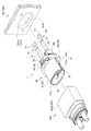
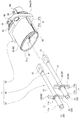
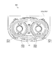
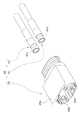
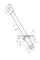
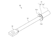
図1から図4の符号1は、本実施形態のコネクタを示す。このコネクタ1は、設置対象物(以下、「コネクタ設置対象物」という。)100に取り付ける(図1、図2及び図4)。尚、後述するように、このコネクタ1においては、インサート成形で雄端子10にハウジング30が一体化される。従って、図3では、説明の便宜上、そのインサート成形後に雄端子10から抜き取ったハウジング30を示している。
Reference numeral 1 in FIGS. 1 to 4 represents the connector of the present embodiment. The connector 1 is attached to an installation object (hereinafter referred to as “connector installation object”) 100 (FIGS. 1, 2, and 4). As will be described later, in the connector 1, the
コネクタ設置対象物100とは、相手方コネクタ200(図1、図5及び図6)の電気接続対象物であって、例えば、車両の駆動装置(電気自動車又はハイブリッド車両の電動機やインバータ等)、負荷としての電気機器(アクチュエータ等)などのことをいう。このコネクタ設置対象物100は、電気接続対象の本体(図示略)と、この本体を保持する保持部材101(図1、図2及び図4)と、を備えている。保持部材101とは、例えば、その本体を収容する収容部材等の筐体、その本体を保持しつつ支えるフレームなどのことをいう。相手方コネクタ200とは、本実施形態のコネクタ1に対して物理的且つ電気的に接続されるコネクタのことをいう。この相手方コネクタ200は、本実施形態のコネクタ1を介してコネクタ設置対象物100の本体に電気的に接続される。
The
コネクタ1は、所謂雄コネクタであって、雄型の端子(以下、「雄端子」という。)10を備える(図1、図3、図4及び図7から図9)。このコネクタ1は、雌コネクタとしての相手方コネクタ200との間で挿入・嵌合させることによって、相手方端子である雌端子201(図5及び図6)に対して雄端子10を物理的且つ電気的に接続させる。
The connector 1 is a so-called male connector and includes a male terminal (hereinafter referred to as “male terminal”) 10 (FIGS. 1, 3, 4, and 7 to 9). The connector 1 is physically and electrically connected to the female terminal 201 (FIGS. 5 and 6) which is a counterpart terminal by inserting and fitting with the
雄端子10は、金属等の導電性材料によって雄型に成形されている。ここでは、銅や銅合金、アルミニウムやアルミニウム合金等の金属材料で成形された雄端子金具を雄端子10の例として挙げる。この雄端子10は、端子接続部11と電気接続部12と連結部13とを備える(図3、図4及び図7から図9)。
The
端子接続部11は、雌端子201に対して物理的且つ電気的に接続させる部位である。この端子接続部11は、筒状に形成し、その外周壁側を雌端子201の端子接続部201a(図5及び図6)との接点とする。雌端子201の端子接続部201aは、自らの内方の空間に雄端子10の端子接続部11を挿入し得るよう筒状に形成されている。ここでは、それぞれの端子接続部11,201aを各々直線の円筒状に形成している。雄端子10の端子接続部11は、雌端子201の端子接続部201aの内方の空間に挿入されることによって、この端子接続部201aに嵌合され、かつ、この端子接続部201aに対して物理的且つ電気的に接続される。雄端子10の端子接続部11は、相手方コネクタ200側(つまり、雌端子201の端子接続部201aに向けた挿入方向側)の端部を先端11aとし、この端部(先端11a)とは逆側の端部を後端11bとする(図3、図4及び図7から図9)。
The
電気接続部12は、コネクタ設置対象物100の本体に対して電気的に接続させる部位である。この電気接続部12は、コネクタ1がコネクタ設置対象物100に取り付けられているときに、筐体としての保持部材101の内部空間に配置され、その内部空間で本体に対して電気的に接続されている。この例示の電気接続部12は、相手方に対して螺子止めすることで物理的且つ電気的に接続させる所謂角型端子の如き形状に形成している。
The
連結部13は、端子接続部11と電気接続部12とを繋げる部位である。この連結部13は、軸状に形成している。この連結部13は、一端に端子接続部11を連結し、他端に電気接続部12を連結している。この例示の連結部13は、直線の円柱状に形成し、端子接続部11の筒軸と同軸上に配置している。この連結部13には、端子接続部11の後端11bが繋がれている。
The connecting
コネクタ1には、この雄端子10が2つ並べて配置されている(図3)。
Two
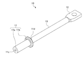
コネクタ1は、更に、端子接続部11の先端11aの電気的絶縁を図る絶縁性の絶縁部材20を備える(図2から図4、図7及び図10)。その絶縁部材20は、合成樹脂等の絶縁性材料で成形する。この絶縁部材20は、雄端子10毎に設ける。尚、後述するように、絶縁部材20は、インサート成形で雄端子10に一体化される。従って、図10では、説明の便宜上、そのインサート成形後に雄端子10から抜き取った絶縁部材20を示している。
The connector 1 further includes an insulating
この絶縁部材20は、端子接続部11の先端11aの電気的絶縁のために利用するのみならず、後述するように、雄端子10の放熱のためにも利用する。よって、この絶縁部材20は、絶縁性材料の中でも熱伝導率の高い材料を用いることが望ましい。また、この絶縁部材20は、後述するハウジング30よりも熱伝導率の高い材料で成形することが望ましい。例えば、ここでは、絶縁部材20にPPS(Poly Phenylene Sulfide)を用い、ハウジング30にPBT(Polybutylene Terephthalate)を用いる。
The insulating
絶縁部材20は、端子接続部11の先端11aに設けた先端絶縁部21を有する(図2から図4、図7及び図10)。その先端絶縁部21は、端子接続部11の先端11aの電気的絶縁を図るための部位である。この先端絶縁部21は、柱状に形成し、端子接続部11の先端11aの端面に先端11aから突出させた状態で配置する。ここでは、円筒状の端子接続部11に合わせて、軸線方向に対する直交断面が円形の柱状となるように先端絶縁部21を形成している。
The insulating
この絶縁部材20は、その先端絶縁部21で端子接続部11の先端11aの電気的絶縁を図るが、この電気的絶縁のための機能だけでなく、雄端子10と雌端子201との間の通電によって発生した熱を逃がすための機能も持っている。
The insulating
雄端子10は、通電に伴い端子接続部11が発熱した場合、その熱を連結部13に伝え、更に連結部13から電気接続部12に伝える。後述するように、雄端子10においては、連結部13の電気接続部12側と電気接続部12とがハウジング30の外方に配置されている。よって、端子接続部11で発生した熱は、例えば、連結部13や電気接続部12を介して、筐体としての保持部材101の内部空間の大気に放散される。しかしながら、大電流が流された場合には、端子接続部11での発熱量が大きくなるので、より多くの熱を放散させる必要がある。
When the
そこで、このコネクタ1においては、端子接続部11で発生した熱が絶縁部材20を介して放散されるように構成する。雄端子10は、端子接続部11で発生した熱の受熱部となる軸部22と、その熱を放散させる放熱部23と、を有している(図4、図7及び図10)。
Therefore, the connector 1 is configured such that heat generated in the
軸部22は、先端絶縁部21から端子接続部11の内方の空間11cに沿って延在させた部位である(図4、図7及び図8)。この軸部22は、その空間11cの内周壁に密着させるように形成して、その内周壁から端子接続部11の熱を受け取る。ここでは、円筒状の端子接続部11に合わせて、軸部22を円柱状に形成している。この軸部22は、端子接続部11の先端11aから後端11bまで延在させている。
The
放熱部23は、端子接続部11の筒軸に対する交差方向で軸部22から端子接続部11の外方に向けて突出させた部位である。つまり、この放熱部23は、軸部22を伝わってきた熱を受け取り、端子接続部11の外方で放熱させることができる。端子接続部11は、内方の空間11cと外方とを連通させる貫通孔11dを有している(図8及び図9)。放熱部23は、その貫通孔11dを介して、端子接続部11の内方の空間11cと外方との間で繋がっている。
The
この放熱部23は、少なくとも1つ設ける。例えば、放熱部23は、軸部22から軸状に突出させたものとして形成する。ここでは、端子接続部11の筒軸に対する直交方向に突出させた軸状の放熱部23を2つ設けている(図3、図4、図7及び図10)。それぞれの放熱部23は、端子接続部11の後端11bで互いに逆向きに突出している。
At least one
コネクタ1は、更に、雄端子10と絶縁部材20とを収容する絶縁性のハウジング30を備える(図1から図4)。そのハウジング30は、合成樹脂等の絶縁性材料で成形する。先に示したように、この例示のPBTで成形されている。
The connector 1 further includes an insulating
このハウジング30は、嵌合部31を有する(図1から図4)。その嵌合部31は、相手方ハウジング202の嵌合部202a(図1、図5及び図6)との間で挿入・嵌合される。嵌合部31は、断面楕円の筒状に形成している。嵌合部202aは、嵌合部31の挿入が可能な断面楕円の内部空間となるよう筒状に形成している。それぞれの嵌合部31,202aの間には、液密性を向上させるためのシール部材41が設けられている(図5)。
The
嵌合部31の内方の空間には、雄端子10及び絶縁部材20の組み合わせを2組収容する。この嵌合部31は、その内方に筒軸方向に沿う2つの円柱状の空間を有しており、そのそれぞれの空間を雄端子収容室32として利用する(図1から図4)。それぞれの雄端子収容室32には、雄端子10及び絶縁部材20の組み合わせが1組ずつ収容される。この例示の雄端子収容室32には、雄端子10の端子接続部11と絶縁部材20の先端絶縁部21及び軸部22とが収容されている。
Two combinations of the
雄端子収容室32は、雄端子10と絶縁部材20とが収容されている状態で、円筒状の空間となる。この円筒状の雄端子収容室32には、コネクタ1と相手方コネクタ200とが挿入・嵌合された際に、相手方ハウジング202の雌端子収容部202b(図5及び図6)が嵌合部31の一端部31aの開口31a1(図1から図4)を介して挿入される。雌端子収容部202bは、円筒状に形成されており、その内方の空間に雌端子201を収容している。よって、雄端子10の端子接続部11は、円筒状の雄端子収容室32に雌端子収容部202bが挿入されることによって、雌端子201の端子接続部201aに挿入・嵌合される。
The male
このように、このハウジング30においては、嵌合部31の内方に雄端子10が収容される。従って、コネクタ1は、ハウジング30の嵌合部31の内方を電気的に遮蔽するシールド部材50を備えている(図1から図4)。そのシールド部材50は、導電性材料で断面楕円の筒状に成形し、互いの筒軸を合わせて嵌合部31に設けている。ここでは、導電性と高い熱伝導率を併せ持つ部材(金属材料等)でシールド部材50を成形する。この例示のシールド部材50は、その嵌合部31の外周壁を外方から覆う筒状のシールド主体51を有している(図1から図4)。また、この例示のシールド部材50は、後述するように、ハウジング30の固定部34(図1から図4)と一緒に、保持部材101の被固定部101a(図1)に対して螺子部材(図示略)で共締めされる。よって、ここでは、その共締めに際して被固定部101aに固定される固定部52をシールド部材50が有している(図4)。その固定部52は、被固定部101aに接触させた状態で固定する。つまり、この例示のシールド部材50は、少なくとも固定部52を含む一部が保持部材101に接触している。
Thus, in the
ハウジング30は、嵌合部31における開口31a1とは逆側の端部(他端部31b)に円筒状の保持部33を有している(図1、図3及び図4)。その保持部33は、雄端子収容室32と同軸上に配置され、その内方の空間で雄端子10の連結部13を保持する。この保持部33は、雄端子10毎に設ける。保持部33には、円筒状のリヤホルダ60が嵌合される(図1、図3及び図4)。連結部13は、そのリヤホルダ60から突出させている。
The
ハウジング30は、コネクタ設置対象物100に取り付ける固定部34を有する(図1から図4)。その固定部34は、嵌合部31の他端部31bにて鍔状に形成された部位である。この固定部34は、コネクタ設置対象物100の被固定部101a(図1)に螺子部材(図示略)を用いた螺子止めで固定する。被固定部101aは、保持部材101の一部である。保持部材101は、嵌合部31の他端部31bを挿通させる貫通孔101b(図1及び図4)を有しており、貫通孔101bの周縁を含む所定領域を被固定部101aとして利用する。その他端部31bと貫通孔101bとの間には、液密性を向上させるための環状のシール部材42(図1、図3及び図4)が設けられている。固定部34と被固定部101aは、他端部31bを貫通孔101bに挿通させている状態で、各々の平面34a,101a1同士が密着する(図4)。このコネクタ1においては、固定部34と被固定部101aとの螺子止めに際して、シールド部材50の固定部52を被固定部101aに接触させた状態で共締めする。
The
先に示した放熱部23は、ハウジング30がコネクタ設置対象物100に取り付けられているときにコネクタ設置対象物100に接触させる。この放熱部23は、そのコネクタ設置対象物100との接触状態を保つために、ハウジング30とコネクタ設置対象物100との間に挟持させることが望ましい。放熱部23は、コネクタ設置対象物100に接触させることによって、軸部22から受け取った熱をコネクタ設置対象物100に伝える。従って、放熱部23は、コネクタ設置対象物100における絶縁部材20よりも熱伝導率の高い部位に接触させることが望ましい。この例示では、コネクタ設置対象物100の保持部材101が絶縁部材20よりも熱伝導率の高いアルミニウムで成形されている。故に、放熱部23は、保持部材101に接触させる。
The
この例示の放熱部23は、保持部材101の被固定部101aに接触させる。この例示では、固定部34の平面34aと面一になるように放熱部23を形成して、固定部34と被固定部101aとが固定された際に放熱部23を被固定部101aに密着させる。つまり、ここでは、固定部34と被固定部101aとで放熱部23が挟持されている。
The illustrated
このように構成しているコネクタ1においては、雄端子10とシールド部材50とが各々成形される。そして、このコネクタ1では、雄端子10が配置された金型において、絶縁部材20がインサート成形される。しかる後、このコネクタ1では、雄端子10及び絶縁部材20の一体化物とシールド部材50とが配置された金型において、ハウジング30がインサート成形される。
In the connector 1 configured as described above, the
コネクタ1は、そのようなインサート成形で形作られるので、雄端子10と絶縁部材20とを密着させることができ、絶縁部材20が雄端子10の熱を受け取ることができる。例えば、絶縁部材20は、端子接続部11の内方の空間11cに軸部22を密着させて配置することができるので、その空間11cの内周壁から発熱源たる端子接続部11の熱を受け取ることができる。
Since the connector 1 is formed by such insert molding, the
また、コネクタ1においては、絶縁部材20に対してもハウジング30がインサート成形されるので、絶縁部材20の放熱部23とハウジング30の固定部34とを密着させることができる。よって、このコネクタ1においては、絶縁部材20とハウジング30との間で高温側から低温側への熱の受け渡しが可能になる。例えば、ハウジング30よりも絶縁部材20の方が高温の場合、放熱部23は、軸部22から受け取った熱をコネクタ設置対象物100に放散させると共に、その熱をハウジング30の固定部34にも放散させることができる。また、ハウジング30よりも絶縁部材20の方が低温の場合、放熱部23は、軸部22から熱を受け取るだけでなく、ハウジング30の固定部34からも熱を受け取ることができる。この場合の放熱部23は、軸部22と固定部34から受け取った熱をコネクタ設置対象物100に放散させる。
Further, in the connector 1, since the
以上示したように、本実施形態のコネクタ1は、通電に伴い発生した雄端子10の熱や雄端子10の発熱に伴うハウジング30の熱を絶縁部材20で受け取り、その受け取った熱をコネクタ設置対象物100等の周囲に放散させることができる。従って、このコネクタ1は、雄端子10の温度上昇を抑えることができ、これに伴い、ハウジング30やハウジング30の内方での温度上昇も抑えることができる。また、本実施形態のコネクタ1は、その受熱と放熱の機能を、端子接続部11の先端11aの電気的絶縁を図るための絶縁部材20に持たせている。つまり、このコネクタ1は、通電に伴う温度上昇を抑えるための専用部品を新たに設けていない。このように、本実施形態のコネクタ1は、部品点数の増加を抑えつつ温度上昇を抑えることができる。
As described above, the connector 1 of the present embodiment receives the heat of the
ここで、このコネクタ1においては、先に示したように、シールド部材50が導電性と高い熱伝導率を併せ持っている。そして、そのシールド部材50は、固定部52を介してコネクタ設置対象物100の保持部材101(被固定部101a)に接触している。つまり、このコネクタ1においては、シールド部材50とコネクタ設置対象物100との間でも伝熱が行われる。そこで、放熱部23は、そのシールド部材50にも接触させる。例えば、放熱部23は、シールド主体51の一部に接触させる。これにより、放熱部23は、自らが受け取った熱をシールド部材50に伝えることができる。つまり、この例示の放熱部23は、シールド部材50を介して、自らが受け取った熱をコネクタ設置対象物100に放散させることができる。従って、本実施形態のコネクタ1は、放熱性を更に向上させたものとなる。
Here, in this connector 1, as shown above, the
1 コネクタ
10 雄端子
11 端子接続部
11a 先端
11c 空間
20 絶縁部材
21 先端絶縁部
22 軸部
23 放熱部
30 ハウジング
34 固定部
50 シールド部材50
100 コネクタ設置対象物
200 相手方コネクタ
201 雌端子(相手方端子)
DESCRIPTION OF SYMBOLS 1
100
Claims (5)
前記端子接続部における相手方コネクタ側の先端の電気的絶縁を図る絶縁性の絶縁部材と、
前記雄端子及び前記絶縁部材を収容する絶縁性のハウジングと、
導電性と高い熱伝導率を併せ持ち、前記ハウジングの内方を電気的に遮蔽するシールド部材と、
を備え、
前記絶縁部材は、前記端子接続部の前記先端に設けた先端絶縁部と、前記先端絶縁部から前記端子接続部の内方の空間に沿って延在させた軸部と、前記端子接続部の筒軸に対する交差方向で前記軸部から前記端子接続部の外方に向けて突出させた部位であり、前記端子接続部の外方での放熱が可能な少なくとも1つの放熱部と、を有し、
前記放熱部は、前記ハウジングと前記シールド部材とに直接接触させ、
前記ハウジングは、前記雄端子と前記シールド部材とに直接接触させることを特徴としたコネクタ。 A male terminal having a contact with the counterpart terminal on the outer peripheral wall side of the cylindrical terminal connecting portion;
An insulating insulating member for electrically insulating the tip of the mating connector side in the terminal connection portion;
An insulating housing that houses the male terminal and the insulating member;
A shield member having both electrical conductivity and high thermal conductivity, and electrically shielding the inside of the housing;
With
The insulating member includes a tip insulating portion provided at the tip of the terminal connecting portion, a shaft portion extending from the tip insulating portion along an inner space of the terminal connecting portion, and a terminal connecting portion. At least one heat dissipating part capable of dissipating heat outside the terminal connecting part, the part projecting from the shaft part toward the outside of the terminal connecting part in a direction intersecting the tube axis. ,
The heat dissipating part is in direct contact with the housing and the shield member ;
The connector is characterized in that the housing is in direct contact with the male terminal and the shield member .
前記放熱部は、前記ハウジングが前記コネクタ設置対象物に取り付けられているときに前記コネクタ設置対象物に接触させることを特徴とした請求項1に記載のコネクタ。 The housing has a fixing portion to be attached to a connector installation object,
The connector according to claim 1, wherein the heat dissipating part is brought into contact with the connector installation object when the housing is attached to the connector installation object.
Priority Applications (4)
| Application Number | Priority Date | Filing Date | Title |
|---|---|---|---|
| JP2017147010A JP6611368B2 (en) | 2017-07-28 | 2017-07-28 | connector |
| US16/044,284 US10205271B1 (en) | 2017-07-28 | 2018-07-24 | Connector |
| CN201810821091.3A CN109309309B (en) | 2017-07-28 | 2018-07-24 | Connector |
| DE102018212378.0A DE102018212378B4 (en) | 2017-07-28 | 2018-07-25 | Interconnects |
Applications Claiming Priority (1)
| Application Number | Priority Date | Filing Date | Title |
|---|---|---|---|
| JP2017147010A JP6611368B2 (en) | 2017-07-28 | 2017-07-28 | connector |
Publications (2)
| Publication Number | Publication Date |
|---|---|
| JP2019029179A JP2019029179A (en) | 2019-02-21 |
| JP6611368B2 true JP6611368B2 (en) | 2019-11-27 |
Family
ID=65003980
Family Applications (1)
| Application Number | Title | Priority Date | Filing Date |
|---|---|---|---|
| JP2017147010A Active JP6611368B2 (en) | 2017-07-28 | 2017-07-28 | connector |
Country Status (4)
| Country | Link |
|---|---|
| US (1) | US10205271B1 (en) |
| JP (1) | JP6611368B2 (en) |
| CN (1) | CN109309309B (en) |
| DE (1) | DE102018212378B4 (en) |
Families Citing this family (9)
| Publication number | Priority date | Publication date | Assignee | Title |
|---|---|---|---|---|
| US10056718B2 (en) | 2016-07-20 | 2018-08-21 | Pic Wire & Cable, Inc. | Electrical connector and modules for high-speed connectivity |
| USD902157S1 (en) * | 2017-07-19 | 2020-11-17 | Pic Wire & Cable, Inc. | Electrical connector |
| JP2020202036A (en) * | 2019-06-06 | 2020-12-17 | 株式会社オートネットワーク技術研究所 | Shield connector |
| CN112086777B (en) * | 2019-06-14 | 2025-05-13 | 深圳市深台帏翔电子有限公司 | Connectors |
| DE102019214024A1 (en) * | 2019-09-13 | 2021-03-18 | Te Connectivity Germany Gmbh | Contact pin with cooling channel system and electrical connector with such a contact pin |
| JP7280234B2 (en) | 2020-11-25 | 2023-05-23 | 矢崎総業株式会社 | connector |
| JP7348238B2 (en) * | 2021-07-29 | 2023-09-20 | 矢崎総業株式会社 | connector |
| DE102022124506A1 (en) * | 2022-09-23 | 2024-03-28 | Kiekert Aktiengesellschaft | Charging connectors for electric and hybrid vehicles |
| DE102023124596A1 (en) * | 2023-09-12 | 2025-03-13 | Kiekert Aktiengesellschaft | System with a charging connector for electric and hybrid vehicles and a heat storage unit |
Family Cites Families (17)
| Publication number | Priority date | Publication date | Assignee | Title |
|---|---|---|---|---|
| EP0282119B1 (en) * | 1987-03-06 | 1993-09-01 | Koninklijke Philips Electronics N.V. | Assembly of a headlight and a connector |
| JP3670495B2 (en) | 1998-11-09 | 2005-07-13 | 矢崎総業株式会社 | Terminal |
| AT410994B (en) * | 2001-08-24 | 2003-09-25 | Akg Acoustics Gmbh | PLUG |
| DE102004057093B3 (en) * | 2004-11-25 | 2006-05-24 | Yazaki Europe Ltd., Hemel Hempstead | connector |
| GB0426585D0 (en) * | 2004-12-06 | 2005-01-05 | Weatherford Lamb | Electrical connector and socket assemblies |
| JP2008041600A (en) | 2006-08-10 | 2008-02-21 | Sumitomo Wiring Syst Ltd | Shield connector |
| JP5182941B2 (en) * | 2008-11-26 | 2013-04-17 | 矢崎総業株式会社 | Composite connector |
| CN201378649Y (en) * | 2009-02-17 | 2010-01-06 | 莫列斯公司 | Electric connector |
| JP5240067B2 (en) * | 2009-05-22 | 2013-07-17 | 日立電線株式会社 | connector |
| JP5334818B2 (en) * | 2009-11-30 | 2013-11-06 | 日立電線株式会社 | Connection structure |
| JP5578927B2 (en) * | 2010-01-12 | 2014-08-27 | 矢崎総業株式会社 | Low insertion force connector |
| US8083533B2 (en) * | 2010-02-11 | 2011-12-27 | Tyco Electronics Corporation | Connector assembly for an interlock circuit |
| DE102011050192A1 (en) * | 2011-05-06 | 2012-11-08 | Aesculap Ag | Surgical coupling system and surgical drive system |
| JP5965810B2 (en) * | 2012-10-02 | 2016-08-10 | 矢崎総業株式会社 | Terminal and terminal manufacturing method |
| JP2016072009A (en) | 2014-09-29 | 2016-05-09 | 株式会社オートネットワーク技術研究所 | Shield connector |
| JP6185900B2 (en) | 2014-11-04 | 2017-08-23 | 矢崎総業株式会社 | connector |
| JP6458996B2 (en) * | 2015-04-24 | 2019-01-30 | 株式会社オートネットワーク技術研究所 | Male connector |
-
2017
- 2017-07-28 JP JP2017147010A patent/JP6611368B2/en active Active
-
2018
- 2018-07-24 CN CN201810821091.3A patent/CN109309309B/en active Active
- 2018-07-24 US US16/044,284 patent/US10205271B1/en active Active
- 2018-07-25 DE DE102018212378.0A patent/DE102018212378B4/en active Active
Also Published As
| Publication number | Publication date |
|---|---|
| CN109309309A (en) | 2019-02-05 |
| DE102018212378A1 (en) | 2019-01-31 |
| CN109309309B (en) | 2020-03-31 |
| JP2019029179A (en) | 2019-02-21 |
| DE102018212378B4 (en) | 2023-06-01 |
| US20190036270A1 (en) | 2019-01-31 |
| US10205271B1 (en) | 2019-02-12 |
Similar Documents
| Publication | Publication Date | Title |
|---|---|---|
| JP6611368B2 (en) | connector | |
| EP3379655B1 (en) | Electrical connector and electrical connection arrangement comprising an electrical connector | |
| JP7280234B2 (en) | connector | |
| JP6709209B2 (en) | Terminals and electric wires with terminals | |
| JP5772742B2 (en) | Electric wire holding device and wire harness | |
| JP6454667B2 (en) | connector | |
| JP7393389B2 (en) | connector | |
| JP7564174B2 (en) | connector | |
| WO2016052089A1 (en) | Shield connector | |
| US20240195121A1 (en) | Connector | |
| JP2007258010A (en) | Electrical connector | |
| JP5170013B2 (en) | Shield connector | |
| CN117096661A (en) | Connector | |
| JP2024134108A (en) | connector | |
| US20240181909A1 (en) | Automotive charging assembly | |
| US20240253487A1 (en) | Connector | |
| JP2020004630A (en) | Charging connector | |
| JP2023169970A (en) | shield connector | |
| JP2005310585A (en) | Connector for equipment | |
| JP2020035673A (en) | Power supply connector and power supply connector with cable | |
| JP2025147811A (en) | connector | |
| JP2019121900A (en) | Connector for on-vehicle camera module and on-vehicle camera module | |
| WO2025239087A1 (en) | Charging inlet | |
| WO2025187316A1 (en) | Connector | |
| CN121011871A (en) | connector |
Legal Events
| Date | Code | Title | Description |
|---|---|---|---|
| A621 | Written request for application examination |
Free format text: JAPANESE INTERMEDIATE CODE: A621 Effective date: 20181018 |
|
| A977 | Report on retrieval |
Free format text: JAPANESE INTERMEDIATE CODE: A971007 Effective date: 20190619 |
|
| A131 | Notification of reasons for refusal |
Free format text: JAPANESE INTERMEDIATE CODE: A131 Effective date: 20190625 |
|
| A521 | Request for written amendment filed |
Free format text: JAPANESE INTERMEDIATE CODE: A523 Effective date: 20190801 |
|
| A02 | Decision of refusal |
Free format text: JAPANESE INTERMEDIATE CODE: A02 Effective date: 20190820 |
|
| A521 | Request for written amendment filed |
Free format text: JAPANESE INTERMEDIATE CODE: A523 Effective date: 20190926 |
|
| A911 | Transfer to examiner for re-examination before appeal (zenchi) |
Free format text: JAPANESE INTERMEDIATE CODE: A911 Effective date: 20191007 |
|
| TRDD | Decision of grant or rejection written | ||
| A01 | Written decision to grant a patent or to grant a registration (utility model) |
Free format text: JAPANESE INTERMEDIATE CODE: A01 Effective date: 20191023 |
|
| A61 | First payment of annual fees (during grant procedure) |
Free format text: JAPANESE INTERMEDIATE CODE: A61 Effective date: 20191028 |
|
| R150 | Certificate of patent or registration of utility model |
Ref document number: 6611368 Country of ref document: JP Free format text: JAPANESE INTERMEDIATE CODE: R150 |
|
| R250 | Receipt of annual fees |
Free format text: JAPANESE INTERMEDIATE CODE: R250 |
|
| S531 | Written request for registration of change of domicile |
Free format text: JAPANESE INTERMEDIATE CODE: R313531 |
|
| R350 | Written notification of registration of transfer |
Free format text: JAPANESE INTERMEDIATE CODE: R350 |
|
| R250 | Receipt of annual fees |
Free format text: JAPANESE INTERMEDIATE CODE: R250 |
|
| R250 | Receipt of annual fees |
Free format text: JAPANESE INTERMEDIATE CODE: R250 |
|
| R250 | Receipt of annual fees |
Free format text: JAPANESE INTERMEDIATE CODE: R250 |