WO2020235393A1 - 車両制御装置 - Google Patents
車両制御装置 Download PDFInfo
- Publication number
- WO2020235393A1 WO2020235393A1 PCT/JP2020/018969 JP2020018969W WO2020235393A1 WO 2020235393 A1 WO2020235393 A1 WO 2020235393A1 JP 2020018969 W JP2020018969 W JP 2020018969W WO 2020235393 A1 WO2020235393 A1 WO 2020235393A1
- Authority
- WO
- WIPO (PCT)
- Prior art keywords
- control device
- vehicle control
- vehicle
- scene
- accelerator
- Prior art date
- Legal status (The legal status is an assumption and is not a legal conclusion. Google has not performed a legal analysis and makes no representation as to the accuracy of the status listed.)
- Ceased
Links
Images

Classifications
-
- B—PERFORMING OPERATIONS; TRANSPORTING
- B60—VEHICLES IN GENERAL
- B60W—CONJOINT CONTROL OF VEHICLE SUB-UNITS OF DIFFERENT TYPE OR DIFFERENT FUNCTION; CONTROL SYSTEMS SPECIALLY ADAPTED FOR HYBRID VEHICLES; ROAD VEHICLE DRIVE CONTROL SYSTEMS FOR PURPOSES NOT RELATED TO THE CONTROL OF A PARTICULAR SUB-UNIT
- B60W50/00—Details of control systems for road vehicle drive control not related to the control of a particular sub-unit, e.g. process diagnostic or vehicle driver interfaces
- B60W50/08—Interaction between the driver and the control system
- B60W50/14—Means for informing the driver, warning the driver or prompting a driver intervention
-
- B—PERFORMING OPERATIONS; TRANSPORTING
- B60—VEHICLES IN GENERAL
- B60W—CONJOINT CONTROL OF VEHICLE SUB-UNITS OF DIFFERENT TYPE OR DIFFERENT FUNCTION; CONTROL SYSTEMS SPECIALLY ADAPTED FOR HYBRID VEHICLES; ROAD VEHICLE DRIVE CONTROL SYSTEMS FOR PURPOSES NOT RELATED TO THE CONTROL OF A PARTICULAR SUB-UNIT
- B60W60/00—Drive control systems specially adapted for autonomous road vehicles
- B60W60/005—Handover processes
- B60W60/0053—Handover processes from vehicle to occupant
- B60W60/0055—Handover processes from vehicle to occupant only part of driving tasks shifted to occupants
-
- G—PHYSICS
- G08—SIGNALLING
- G08G—TRAFFIC CONTROL SYSTEMS
- G08G1/00—Traffic control systems for road vehicles
- G08G1/09—Arrangements for giving variable traffic instructions
-
- B—PERFORMING OPERATIONS; TRANSPORTING
- B60—VEHICLES IN GENERAL
- B60W—CONJOINT CONTROL OF VEHICLE SUB-UNITS OF DIFFERENT TYPE OR DIFFERENT FUNCTION; CONTROL SYSTEMS SPECIALLY ADAPTED FOR HYBRID VEHICLES; ROAD VEHICLE DRIVE CONTROL SYSTEMS FOR PURPOSES NOT RELATED TO THE CONTROL OF A PARTICULAR SUB-UNIT
- B60W50/00—Details of control systems for road vehicle drive control not related to the control of a particular sub-unit, e.g. process diagnostic or vehicle driver interfaces
- B60W50/08—Interaction between the driver and the control system
- B60W50/14—Means for informing the driver, warning the driver or prompting a driver intervention
- B60W2050/146—Display means
-
- B—PERFORMING OPERATIONS; TRANSPORTING
- B60—VEHICLES IN GENERAL
- B60W—CONJOINT CONTROL OF VEHICLE SUB-UNITS OF DIFFERENT TYPE OR DIFFERENT FUNCTION; CONTROL SYSTEMS SPECIALLY ADAPTED FOR HYBRID VEHICLES; ROAD VEHICLE DRIVE CONTROL SYSTEMS FOR PURPOSES NOT RELATED TO THE CONTROL OF A PARTICULAR SUB-UNIT
- B60W2540/00—Input parameters relating to occupants
- B60W2540/10—Accelerator pedal position
- B60W2540/103—Accelerator thresholds, e.g. kickdown
-
- B—PERFORMING OPERATIONS; TRANSPORTING
- B60—VEHICLES IN GENERAL
- B60W—CONJOINT CONTROL OF VEHICLE SUB-UNITS OF DIFFERENT TYPE OR DIFFERENT FUNCTION; CONTROL SYSTEMS SPECIALLY ADAPTED FOR HYBRID VEHICLES; ROAD VEHICLE DRIVE CONTROL SYSTEMS FOR PURPOSES NOT RELATED TO THE CONTROL OF A PARTICULAR SUB-UNIT
- B60W2540/00—Input parameters relating to occupants
- B60W2540/18—Steering angle
-
- B—PERFORMING OPERATIONS; TRANSPORTING
- B60—VEHICLES IN GENERAL
- B60W—CONJOINT CONTROL OF VEHICLE SUB-UNITS OF DIFFERENT TYPE OR DIFFERENT FUNCTION; CONTROL SYSTEMS SPECIALLY ADAPTED FOR HYBRID VEHICLES; ROAD VEHICLE DRIVE CONTROL SYSTEMS FOR PURPOSES NOT RELATED TO THE CONTROL OF A PARTICULAR SUB-UNIT
- B60W2552/00—Input parameters relating to infrastructure
- B60W2552/05—Type of road, e.g. motorways, local streets, paved or unpaved roads
-
- B—PERFORMING OPERATIONS; TRANSPORTING
- B60—VEHICLES IN GENERAL
- B60W—CONJOINT CONTROL OF VEHICLE SUB-UNITS OF DIFFERENT TYPE OR DIFFERENT FUNCTION; CONTROL SYSTEMS SPECIALLY ADAPTED FOR HYBRID VEHICLES; ROAD VEHICLE DRIVE CONTROL SYSTEMS FOR PURPOSES NOT RELATED TO THE CONTROL OF A PARTICULAR SUB-UNIT
- B60W2552/00—Input parameters relating to infrastructure
- B60W2552/30—Road curve radius
Definitions
- This disclosure relates to a vehicle control device.
- Patent Document 1 The self-driving vehicle is disclosed in Patent Document 1, for example.
- vehicles that can be driven automatically and manually If the driver performs a brake operation or the like while the vehicle is automatically driving, the automatic driving function is turned off.
- the driver may want to drive at a vehicle speed higher than the vehicle speed set by the automatic driving function.
- a specific scene for example, there is an exit route of a car-only road. If the driver wants to drive at a vehicle speed higher than the vehicle speed set by the automatic driving function, the driver has to turn off the automatic driving function by performing a brake operation or the like.
- a vehicle control device capable of turning off at least a part of the automatic driving function without necessarily performing a braking operation.
- One aspect of the present disclosure is a vehicle control device provided in a vehicle capable of automatic driving and manual driving, and a specific scene determination configured to determine whether or not the vehicle is in a preset specific scene.
- a specific operation determination unit configured to determine whether or not the unit and the driver of the vehicle have performed a specific operation including an accelerator operation, and when the vehicle is performing the automatic driving, the vehicle is said to be said.
- the specific scene determination unit determines that the vehicle is in a specific scene and the specific operation determination unit determines that the driver has performed the specific operation, the function of turning off at least a part of the automatic driving function is turned off.
- the vehicle control device which is one aspect of the present disclosure, can turn off at least a part of the automatic driving function without necessarily performing the braking operation.
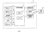
- FIG. 1 The configuration of the vehicle control device 1 will be described with reference to FIGS. 1 and 2.
- the vehicle control device 1 is mounted on the vehicle 3.
- the vehicle 3 can be automatically driven and manually driven.
- automatic operation may be referred to as AD.
- AD on when the automatic operation function is on, it may be called AD on.
- AD off when the automatic driving function is off, it may be called AD off.
- the AD off is a state in which the driver of the vehicle 3 manually drives the vehicle.
- the state of the vehicle 3 is switched from AD on to AD off by the process of step 3 described later. Further, the state of the vehicle 3 is switched from AD off to AD on by a known trigger.
- the vehicle control device 1 includes a microcomputer having a CPU 5 and, for example, a semiconductor memory such as RAM or ROM (hereinafter referred to as memory 7).
- a microcomputer having a CPU 5 and, for example, a semiconductor memory such as RAM or ROM (hereinafter referred to as memory 7).
- Each function of the vehicle control device 1 is realized by the CPU 5 executing a program stored in a non-transitional substantive recording medium.
- the memory 7 corresponds to a non-transitional substantive recording medium in which a program is stored.
- the method corresponding to the program is executed.
- the vehicle control device 1 may include one microcomputer or a plurality of microcomputers.
- the vehicle control device 1 includes a state determination unit 9, a specific scene determination unit 11, a specific operation determination unit 13, a function off unit 15, a scene acquisition unit 17, and a threshold setting unit 19.
- a threshold value display unit 21, a notification unit 23, an automatic operation execution unit 25, and an override unit 26 are provided.
- the vehicle 3 includes a peripheral sensor 27, a vehicle sensor 29, a vehicle control actuator 31, a GPS 33, an AD switch 35, an information presentation unit 37, a communication unit 39, and information for automatic driving. It includes DB41.
- the vehicle control device 1 is connected to these configurations.
- the peripheral sensor 27 detects a target existing around the vehicle 3.
- the peripheral sensor 27 includes, for example, a camera, a rider, and the like.
- the vehicle sensor 29 detects the driving operation of the driver of the vehicle 3. Driving operations include accelerator operation, brake operation, steering operation, and the like.
- the vehicle sensor 29 can detect the amount of depression of the accelerator, the amount of depression of the brake, the amount of steering operation, and the like.
- the vehicle control actuator 31 controls the running state of the vehicle 3 in response to an instruction from the vehicle control device 1.
- the contents of control include acceleration, deceleration, steering and the like.
- GPS 33 acquires the position information of the vehicle 3.
- the AD switch 35 is a switch that can be operated by the driver.
- the state of the vehicle 3 is switched from AD on to AD off, triggered by the operation of the AD switch 35. Further, the state of the vehicle 3 is switched from AD off to AD on, triggered by the operation of the AD switch 35.
- the information presentation unit 37 is provided in the vehicle interior of the vehicle 3.
- the information presentation unit 37 includes, for example, a display and a speaker.
- the information presentation unit 37 can present information to the driver by image or sound.
- the communication unit 39 can perform wireless communication with the information center 43 outside the vehicle 3.
- the communication unit 39 can receive, for example, traffic information, weather information, map information described later, and the like from the information center 43.
- the automatic driving information DB 41 stores map information and the like.
- Map information includes road profiles, number of lanes on roads, speed limits on roads, intersection locations, pedestrian crossing locations, and the like.
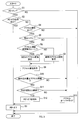
- step 1 of FIG. 3 the state determination unit 9 determines whether or not AD is on at the present time. If it is determined that AD is on, this process proceeds to step 2. If it is determined that the AD is off, this process ends and the AD off continues.
- step 2 the function off unit 15 determines whether or not there has been an AD off operation by the driver.
- the AD off operation includes, for example, an operation of the AD switch 35, a brake operation, a steering operation, and the like.
- the function off unit 15 can detect the brake operation and the steering operation by using the vehicle sensor 29. If there is an AD off operation, this process proceeds to step 3. If there is no AD off operation, this process proceeds to step 4.
- step 3 the function off unit 15 switches the state of the vehicle 3 from AD on to AD off.
- step 4 the specific operation determination unit 13 determines whether or not the driver has operated the accelerator.
- the specific operation determination unit 13 can detect the accelerator operation by using the vehicle sensor 29. When the driver operates the accelerator, this process proceeds to step 5. If the driver does not operate the accelerator, this process ends and AD on continues.
- the automatic driving execution unit 25 performs automatic driving by a known method using the peripheral sensor 27, the vehicle control actuator 31, GPS33, the automatic driving information DB 41, and the like.
- step 5 the scene acquisition unit 17 first acquires the scene in which the vehicle 3 currently exists (hereinafter referred to as the current scene).
- a scene is a place.
- the scene acquisition unit 17 acquires the current scene by collating, for example, the position information of the vehicle 3 acquired by using GPS 33 with the map information stored in the automatic driving information DB 41.
- the scene acquisition unit 17 detects landmarks existing around the vehicle 3 by using, for example, the peripheral sensor 27. Examples of landmarks include buildings, terrain, and the like. Next, the scene acquisition unit 17 acquires the relative position information of the vehicle 3 with respect to the detected landmark. Next, the scene acquisition unit 17 acquires the absolute position information of the detected landmark from the map information. Next, the scene acquisition unit 17 acquires the current scene from the relative position information of the vehicle 3 with respect to the detected landmark and the absolute position information of the detected landmark.
- landmarks include buildings, terrain, and the like.
- the scene acquisition unit 17 acquires the relative position information of the vehicle 3 with respect to the detected landmark.
- the scene acquisition unit 17 acquires the absolute position information of the detected landmark from the map information.
- the scene acquisition unit 17 acquires the current scene from the relative position information of the vehicle 3 with respect to the detected landmark and the absolute position information of the detected landmark.
- the specific scene determination unit 11 determines whether or not the current scene is a preset specific scene.
- the specific scene is, for example, a scene in which the driver often desires to drive at a vehicle speed higher than the vehicle speed set by the automatic driving function by turning off AD.
- the specific scene is, for example, a scene in which the vehicle speed set by the automatic driving function is lower than that of other scenes.
- Specific scenes include, for example, a scene of a junction, a scene of an exit road, a scene of a ramp, a scene immediately before an ETC (registered trademark) gate, a scene immediately after an ETC gate, a scene before a curve, and the like.
- step 6 If the current scene is a specific scene, this process proceeds to step 6. If the current scene is not a specific scene, this process proceeds to step 13.
- the threshold setting unit 19 determines whether or not the current scene acquired in step 5 is a scene in which the accelerator threshold needs to be changed (hereinafter referred to as a threshold change scene).
- the threshold change scene is preset.
- the threshold value change scene is, for example, a scene in which an appropriate vehicle speed for safe driving is different from other scenes. Examples of the threshold value changing scene include a scene with a curve having a small curvature, a scene near ETC, and the like.
- the accelerator threshold value is a threshold value used in the determination in step 10 described later.
- step 7 If the current scene is a threshold change scene, this process proceeds to step 7. If the current scene is not a threshold change scene, this process proceeds to step 8.
- step 7 the threshold setting unit 19 sets a special accelerator threshold as the accelerator threshold.
- the special accelerator threshold is a positive value and is smaller than the normal accelerator threshold described later.
- step 8 the threshold setting unit 19 sets a normal accelerator threshold as the accelerator threshold.
- the normal accelerator threshold is a positive value and is greater than the special accelerator threshold.
- the processes of steps 6 to 8 correspond to setting the accelerator threshold value according to the scene in which the vehicle 3 is traveling.
- step 9 the threshold value display unit 21 uses the information presentation unit 37 to display the accelerator threshold value set in step 7 or step 8.
- step 10 the specific operation determination unit 13 determines whether or not the amount of depression of the accelerator is equal to or greater than the accelerator threshold value set in step 7 or step 8. If the amount of depression of the accelerator is equal to or greater than the accelerator threshold value, this process proceeds to step 11. If the amount of depression of the accelerator is less than the accelerator threshold value, this process proceeds to step 13.
- step 11 the specific operation determination unit 13 determines whether or not the accelerator operation continues for a predetermined time or longer. If the accelerator operation continues for a predetermined time or longer, this process proceeds to step 12. If the accelerator operation has not continued for a predetermined time or more, this process proceeds to step 13.
- step 12 the notification unit 23 uses the information presentation unit 37 to notify that AD is turned off after that. After step 12, the process proceeds to step 3.
- step 13 the override unit 26 performs accelerator override.
- Accelerator override is a process of setting the accelerator opening to a value corresponding to the accelerator operation by the driver while AD is on.
- step 5 the vehicle control device 1 determines whether or not the vehicle 3 is in a specific scene. Further, in the steps 4, 10 and 11, the vehicle control device 1 determines whether or not the driver has performed an accelerator operation in which the amount of depression of the accelerator exceeds the accelerator threshold value and continues for a predetermined time or longer. When the vehicle control device 1 determines that the vehicle 3 is in a specific scene when AD is on, and determines that the amount of depression of the accelerator exceeds the accelerator threshold value and the driver performs an accelerator operation that continues for a predetermined time or longer. The state of the vehicle 3 is switched to AD off.
- the vehicle control device 1 can switch the state of the vehicle 3 to AD off even if the driver does not necessarily perform the braking operation.
- An accelerator operation in which the amount of depression of the accelerator exceeds the accelerator threshold value and continues for a predetermined time or longer corresponds to a specific operation.
- the specific operation is an operation including an accelerator operation in which the amount of depression of the accelerator exceeds the accelerator threshold value. Therefore, the vehicle control device 1 can prevent the AD from being turned off when the driver does not want the AD to be turned off.
- the vehicle control device 1 can appropriately set the accelerator threshold value according to the scene in which the vehicle 3 is traveling by the processes of steps 6 to 8.
- the vehicle control device 1 can display the accelerator threshold value. Therefore, the driver can easily understand how much the accelerator operation should be performed to turn off the AD.
- the specific operation is an operation including an accelerator operation that continues for a predetermined time or longer. Therefore, the vehicle control device 1 can prevent the AD from being turned off when the driver does not want the AD to be turned off.
- the specific scene includes the scene of the confluence and the scene of the exit route.
- the scene of the confluence and the scene of the exit road are scenes in which the driver often desires to switch the state of the vehicle 3 to AD off.
- the vehicle control device 1 can switch the state of the vehicle 3 to AD off in the scene of the junction and the scene of the exit route.
- the specific operation is an accelerator operation in which the amount of depression of the accelerator exceeds the accelerator threshold value and continues for a predetermined time or longer.
- the second embodiment is different from the first embodiment in that the specific operation includes a steering operation in addition to the specific operation in the first embodiment. That is, the specific operation in the second embodiment is an operation in which both the accelerator operation and the steering operation are performed.
- the specific operation is an operation of performing both an accelerator operation and a steering operation.
- the specific scene includes the scene before the curve. Therefore, the vehicle control device 1 switches the state of the vehicle 3 to AD off when both the accelerator operation and the steering operation are performed in the scene before the curve. Therefore, when only the accelerator operation is performed in the scene before the curve, the AD is not turned off, so that the safety of the vehicle 3 is further improved.
- step 11 when a positive judgment was made in step 11, all the automatic driving functions were turned off in step 3.
- the automatic operation function when the affirmative judgment is made in the step 11, the automatic operation function is basically turned off in the step 3, but the lateral control function is continued for a predetermined time. Lateral control is steering control. If a positive judgment is made in step 2, for example, all the automatic driving functions are turned off.
- the vehicle control device 1 When the driver performs a specific operation in a specific scene, the vehicle control device 1 continues the lateral control function for a predetermined time. As a result, the safety of the vehicle 3 is further improved. In particular, when a specific operation is performed while the vehicle 3 is changing lanes in a scene of a junction or an exit road, the safety of the vehicle 3 is further improved by continuing the lateral control function for a predetermined time. improves. ⁇ Other embodiments> Although the embodiments of the present disclosure have been described above, the present disclosure is not limited to the above-described embodiments, and can be implemented in various modifications.
- the specific operation may be a combination of an accelerator operation and another driving operation.
- the other driving operation may be a driving operation other than the steering operation.
- the accelerator threshold value may always be constant.
- the vehicle control device 1 and its method described in the present disclosure are provided by configuring a processor and memory programmed to perform one or more functions embodied by a computer program. It may be realized by a dedicated computer. Alternatively, the vehicle control device 1 and its method described in the present disclosure may be realized by a dedicated computer provided by configuring a processor with one or more dedicated hardware logic circuits. Alternatively, the vehicle control unit 1 and its method described in the present disclosure comprises a processor and memory programmed to perform one or more functions and a processor composed of one or more hardware logic circuits. It may be realized by one or more dedicated computers configured by a combination.
- the computer program may also be stored on a computer-readable non-transitional tangible recording medium as an instruction executed by the computer.
- the method for realizing the functions of each part included in the vehicle control device 1 does not necessarily include software, and all the functions may be realized by using one or a plurality of hardware.
- a plurality of functions possessed by one component in the above embodiment may be realized by a plurality of components, or one function possessed by one component may be realized by a plurality of components. .. Further, a plurality of functions possessed by the plurality of components may be realized by one component, or one function realized by the plurality of components may be realized by one component. Further, a part of the configuration of the above embodiment may be omitted. In addition, at least a part of the configuration of the above embodiment may be added or replaced with the configuration of the other above embodiment.
- a system having the vehicle control device 1 as a component, a program for operating a computer as the vehicle control device 1, a non-transitional non-transitional such as a semiconductor memory in which this program is recorded In addition to the vehicle control device 1 described above, a system having the vehicle control device 1 as a component, a program for operating a computer as the vehicle control device 1, a non-transitional non-transitional such as a semiconductor memory in which this program is recorded.
- the present disclosure can also be realized in various forms such as an actual recording medium and a vehicle control method.
Landscapes
- Engineering & Computer Science (AREA)
- Automation & Control Theory (AREA)
- Human Computer Interaction (AREA)
- Transportation (AREA)
- Mechanical Engineering (AREA)
- Physics & Mathematics (AREA)
- General Physics & Mathematics (AREA)
- Control Of Driving Devices And Active Controlling Of Vehicle (AREA)
- Traffic Control Systems (AREA)
Priority Applications (1)
| Application Number | Priority Date | Filing Date | Title |
|---|---|---|---|
| US17/529,379 US20220073109A1 (en) | 2019-05-21 | 2021-11-18 | Vehicle control unit |
Applications Claiming Priority (2)
| Application Number | Priority Date | Filing Date | Title |
|---|---|---|---|
| JP2019095249A JP2020190870A (ja) | 2019-05-21 | 2019-05-21 | 車両制御装置 |
| JP2019-095249 | 2019-05-21 |
Related Child Applications (1)
| Application Number | Title | Priority Date | Filing Date |
|---|---|---|---|
| US17/529,379 Continuation US20220073109A1 (en) | 2019-05-21 | 2021-11-18 | Vehicle control unit |
Publications (1)
| Publication Number | Publication Date |
|---|---|
| WO2020235393A1 true WO2020235393A1 (ja) | 2020-11-26 |
Family
ID=73454642
Family Applications (1)
| Application Number | Title | Priority Date | Filing Date |
|---|---|---|---|
| PCT/JP2020/018969 Ceased WO2020235393A1 (ja) | 2019-05-21 | 2020-05-12 | 車両制御装置 |
Country Status (3)
| Country | Link |
|---|---|
| US (1) | US20220073109A1 (enExample) |
| JP (1) | JP2020190870A (enExample) |
| WO (1) | WO2020235393A1 (enExample) |
Cited By (1)
| Publication number | Priority date | Publication date | Assignee | Title |
|---|---|---|---|---|
| JP2023146207A (ja) * | 2022-03-29 | 2023-10-12 | 本田技研工業株式会社 | 運転支援システム |
Citations (5)
| Publication number | Priority date | Publication date | Assignee | Title |
|---|---|---|---|---|
| JP2012162221A (ja) * | 2011-02-09 | 2012-08-30 | Honda Motor Co Ltd | 自動制動装置 |
| JP2016175613A (ja) * | 2015-03-23 | 2016-10-06 | トヨタ自動車株式会社 | 自動運転装置 |
| JP2017146933A (ja) * | 2016-02-19 | 2017-08-24 | 住友電気工業株式会社 | 情報処理装置、車載装置、記憶媒体及びコンピュータプログラム |
| JP2017197053A (ja) * | 2016-04-28 | 2017-11-02 | トヨタ自動車株式会社 | 自動運転制御装置 |
| JP2018088060A (ja) * | 2016-11-28 | 2018-06-07 | トヨタ自動車株式会社 | 自動運転装置 |
Family Cites Families (10)
| Publication number | Priority date | Publication date | Assignee | Title |
|---|---|---|---|---|
| JP5163346B2 (ja) * | 2008-07-31 | 2013-03-13 | 日産自動車株式会社 | 車両の制駆動制御装置及び自動運転制御方法 |
| WO2015093305A1 (ja) * | 2013-12-18 | 2015-06-25 | 本田技研工業株式会社 | 操作量表示装置 |
| JP6176264B2 (ja) * | 2015-01-19 | 2017-08-09 | トヨタ自動車株式会社 | 自動運転車両システム |
| JP6375237B2 (ja) * | 2015-01-28 | 2018-08-15 | 日立オートモティブシステムズ株式会社 | 自動運転制御装置 |
| JP6627332B2 (ja) * | 2015-08-31 | 2020-01-08 | いすゞ自動車株式会社 | 運転支援装置および運転支援方法 |
| JP6464107B2 (ja) * | 2016-02-22 | 2019-02-06 | 本田技研工業株式会社 | 走行支援装置 |
| JP6358478B2 (ja) * | 2016-03-31 | 2018-07-18 | マツダ株式会社 | 車両用効果音発生装置 |
| KR101911293B1 (ko) * | 2016-05-12 | 2018-10-24 | 엘지전자 주식회사 | 차량용 제어장치 |
| WO2018134994A1 (ja) * | 2017-01-23 | 2018-07-26 | 本田技研工業株式会社 | 車両制御システム、車両制御方法、および車両制御プログラム |
| JP7205773B2 (ja) * | 2019-03-27 | 2023-01-17 | スズキ株式会社 | 車両の走行制御装置 |
-
2019
- 2019-05-21 JP JP2019095249A patent/JP2020190870A/ja active Pending
-
2020
- 2020-05-12 WO PCT/JP2020/018969 patent/WO2020235393A1/ja not_active Ceased
-
2021
- 2021-11-18 US US17/529,379 patent/US20220073109A1/en not_active Abandoned
Patent Citations (5)
| Publication number | Priority date | Publication date | Assignee | Title |
|---|---|---|---|---|
| JP2012162221A (ja) * | 2011-02-09 | 2012-08-30 | Honda Motor Co Ltd | 自動制動装置 |
| JP2016175613A (ja) * | 2015-03-23 | 2016-10-06 | トヨタ自動車株式会社 | 自動運転装置 |
| JP2017146933A (ja) * | 2016-02-19 | 2017-08-24 | 住友電気工業株式会社 | 情報処理装置、車載装置、記憶媒体及びコンピュータプログラム |
| JP2017197053A (ja) * | 2016-04-28 | 2017-11-02 | トヨタ自動車株式会社 | 自動運転制御装置 |
| JP2018088060A (ja) * | 2016-11-28 | 2018-06-07 | トヨタ自動車株式会社 | 自動運転装置 |
Cited By (2)
| Publication number | Priority date | Publication date | Assignee | Title |
|---|---|---|---|---|
| JP2023146207A (ja) * | 2022-03-29 | 2023-10-12 | 本田技研工業株式会社 | 運転支援システム |
| JP7731838B2 (ja) | 2022-03-29 | 2025-09-01 | 本田技研工業株式会社 | 運転支援システム |
Also Published As
| Publication number | Publication date |
|---|---|
| JP2020190870A (ja) | 2020-11-26 |
| US20220073109A1 (en) | 2022-03-10 |
Similar Documents
| Publication | Publication Date | Title |
|---|---|---|
| JP6974664B2 (ja) | 自動運転制御装置及び車両 | |
| CN107567406B (zh) | 基于操作者超控的自动化车辆参数修改 | |
| JP7004077B2 (ja) | 車両の走行制御方法及び走行制御装置 | |
| JP7119653B2 (ja) | 車両制御装置 | |
| CN109421713B (zh) | 车辆控制装置、车辆控制方法及存储介质 | |
| CN113495560B (zh) | 基于场景的自动驾驶车辆控制 | |
| CN109476307B (zh) | 行驶控制方法及行驶控制装置 | |
| CN110171421B (zh) | 车辆控制装置 | |
| US10452932B2 (en) | Information processing device | |
| JP2017178267A (ja) | 運転支援方法およびそれを利用した運転支援装置、自動運転制御装置、車両、プログラム | |
| WO2018012180A1 (ja) | 走行制御方法及び走行制御装置 | |
| WO2018163471A1 (ja) | 運転モード切替制御装置、システム、方法、およびプログラム | |
| CN109664883B (zh) | 车辆控制装置 | |
| JP2018151962A (ja) | 駐車支援方法およびそれを利用した駐車支援装置、自動運転制御装置、プログラム | |
| CN111532268A (zh) | 车辆及其控制装置以及控制方法 | |
| JPWO2018198264A1 (ja) | 方向指示器の制御方法及び方向指示器の制御装置 | |
| JP7425911B2 (ja) | 制御装置、制御方法及びプログラム | |
| WO2020235393A1 (ja) | 車両制御装置 | |
| JP7029689B2 (ja) | 表示制御方法およびそれを利用した表示制御装置、車両、プログラム、表示制御システム | |
| JP7043982B2 (ja) | 車両制御装置 | |
| JP2020154506A (ja) | 煽り運転警告装置、及び煽り運転警告プログラム | |
| WO2022230779A1 (ja) | 車両用報知制御装置及び車両用報知制御方法 | |
| JP7256867B2 (ja) | 制御装置、制御方法及びプログラム | |
| JP7303521B2 (ja) | 車両制御装置 | |
| US11273831B2 (en) | Vehicle and control device for the same |
Legal Events
| Date | Code | Title | Description |
|---|---|---|---|
| 121 | Ep: the epo has been informed by wipo that ep was designated in this application |
Ref document number: 20809276 Country of ref document: EP Kind code of ref document: A1 |
|
| NENP | Non-entry into the national phase |
Ref country code: DE |
|
| 122 | Ep: pct application non-entry in european phase |
Ref document number: 20809276 Country of ref document: EP Kind code of ref document: A1 |