WO2020235366A1 - コネクタ - Google Patents
コネクタ Download PDFInfo
- Publication number
- WO2020235366A1 WO2020235366A1 PCT/JP2020/018758 JP2020018758W WO2020235366A1 WO 2020235366 A1 WO2020235366 A1 WO 2020235366A1 JP 2020018758 W JP2020018758 W JP 2020018758W WO 2020235366 A1 WO2020235366 A1 WO 2020235366A1
- Authority
- WO
- WIPO (PCT)
- Prior art keywords
- plate portion
- front plate
- terminal
- detection hole
- terminal fitting
- Prior art date
- Legal status (The legal status is an assumption and is not a legal conclusion. Google has not performed a legal analysis and makes no representation as to the accuracy of the status listed.)
- Ceased
Links
Images


Classifications
-
- H—ELECTRICITY
- H01—ELECTRIC ELEMENTS
- H01R—ELECTRICALLY-CONDUCTIVE CONNECTIONS; STRUCTURAL ASSOCIATIONS OF A PLURALITY OF MUTUALLY-INSULATED ELECTRICAL CONNECTING ELEMENTS; COUPLING DEVICES; CURRENT COLLECTORS
- H01R13/00—Details of coupling devices of the kinds covered by groups H01R12/70 or H01R24/00 - H01R33/00
- H01R13/40—Securing contact members in or to a base or case; Insulating of contact members
- H01R13/42—Securing in a demountable manner
- H01R13/424—Securing in base or case composed of a plurality of insulating parts having at least one resilient insulating part
-
- H—ELECTRICITY
- H01—ELECTRIC ELEMENTS
- H01R—ELECTRICALLY-CONDUCTIVE CONNECTIONS; STRUCTURAL ASSOCIATIONS OF A PLURALITY OF MUTUALLY-INSULATED ELECTRICAL CONNECTING ELEMENTS; COUPLING DEVICES; CURRENT COLLECTORS
- H01R13/00—Details of coupling devices of the kinds covered by groups H01R12/70 or H01R24/00 - H01R33/00
- H01R13/40—Securing contact members in or to a base or case; Insulating of contact members
- H01R13/42—Securing in a demountable manner
- H01R13/422—Securing in resilient one-piece base or case, e.g. by friction; One-piece base or case formed with resilient locking means
- H01R13/4223—Securing in resilient one-piece base or case, e.g. by friction; One-piece base or case formed with resilient locking means comprising integral flexible contact retaining fingers
-
- G—PHYSICS
- G01—MEASURING; TESTING
- G01R—MEASURING ELECTRIC VARIABLES; MEASURING MAGNETIC VARIABLES
- G01R31/00—Arrangements for testing electric properties; Arrangements for locating electric faults; Arrangements for electrical testing characterised by what is being tested not provided for elsewhere
- G01R31/50—Testing of electric apparatus, lines, cables or components for short-circuits, continuity, leakage current or incorrect line connections
- G01R31/66—Testing of connections, e.g. of plugs or non-disconnectable joints
-
- H—ELECTRICITY
- H01—ELECTRIC ELEMENTS
- H01R—ELECTRICALLY-CONDUCTIVE CONNECTIONS; STRUCTURAL ASSOCIATIONS OF A PLURALITY OF MUTUALLY-INSULATED ELECTRICAL CONNECTING ELEMENTS; COUPLING DEVICES; CURRENT COLLECTORS
- H01R13/00—Details of coupling devices of the kinds covered by groups H01R12/70 or H01R24/00 - H01R33/00
- H01R13/02—Contact members
- H01R13/10—Sockets for co-operation with pins or blades
- H01R13/11—Resilient sockets
- H01R13/113—Resilient sockets co-operating with pins or blades having a rectangular transverse section
Definitions
- This disclosure relates to connectors.
- Patent Document 1 discloses a connector in which a terminal fitting is inserted in a terminal accommodating chamber of a connector housing.
- the front wall of the connector housing has an insertion hole for inserting the tab of the mating terminal into the terminal accommodating chamber.
- the tab inserted into the insertion hole comes into contact with the electrical contact portion at the front end of the terminal fitting.
- the inspection pin When performing a continuity inspection on the connector of Patent Document 1, the inspection pin is inserted into the insertion hole and the tip of the inspection pin is abutted against the electrical contact portion.
- the electrical contact portion is an important part in terms of function as a terminal fitting. Therefore, when the inspection pin is abutted against the electrical contact portion, there is a concern that the electrical contact portion will be deformed and the terminal fitting will not be able to perform its original function.
- the connector of the present disclosure has been completed based on the above circumstances, and an object thereof is to prevent damage or deformation of the terminal fitting.
- the connectors of this disclosure are A housing with a terminal storage chamber and It has a tubular portion and an elastic contact piece housed in the tubular portion, and is provided with a terminal fitting inserted into the terminal accommodating chamber.
- a tab insertion hole is formed in the front wall portion of the housing so that the tab of the mating terminal enters the tubular portion from the front and is inserted so as to come into contact with the elastic contact piece.
- a front plate portion is formed in front of the elastic contact piece in the terminal fitting.
- a detection hole opened separately from the tab insertion hole is formed in the front wall portion of the housing. The detection hole is arranged at a position of the front wall portion facing the front plate portion.
- FIG. 1 is a front view of the connector of the first embodiment.
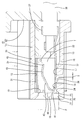
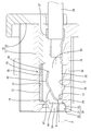
- FIG. 2 is a side sectional view showing a state in which the detection pin inserted into the detection hole is in contact with the front plate portion of the terminal fitting.
- FIG. 3 is a side sectional view showing a state in which the detection pin pushes the terminal fitting backward and moves it.
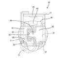
- FIG. 4 is a perspective view of the terminal fitting.
- FIG. 5 is a front sectional view showing a state in which the detection pin is in contact with the front plate portion of the terminal fitting.
- FIG. 6 is a front view of the terminal fitting of the second embodiment.
- FIG. 7 is a perspective view of the terminal fitting of the third embodiment.
- FIG. 8 is a front view of the terminal fitting of the fourth embodiment.
- the connectors of this disclosure are (1) A housing having a terminal accommodating chamber, a tubular portion, and a terminal fitting having an elastic contact piece accommodated in the tubular portion and inserted into the terminal accommodating chamber, and a front wall portion of the housing. Is formed with a tab insertion hole in which the tab of the mating terminal enters the tubular portion from the front and is inserted so as to come into contact with the elastic contact piece, and the terminal fitting is in front of the elastic contact piece.
- the front plate portion is formed, and a detection hole opened separately from the tab insertion hole is formed in the front wall portion of the housing, and the detection hole is the same as the front plate portion in the front wall portion. It is arranged in the opposite position.
- the detection pin is inserted into the detection hole and brought into contact with the front plate portion. Since the front plate portion is located in front of the elastic contact piece, there is no possibility that the detection pin will come into contact with the elastic contact piece. Since the detection hole is opened separately from the tab insertion hole and the tab insertion hole and the detection hole do not communicate with each other, the detection pin inserted into the detection hole may mistakenly enter the tab insertion hole and come into contact with the elastic contact piece. Absent. Therefore, according to the connector of the present disclosure, it is possible to prevent damage or deformation of the elastic contact piece due to the contact of the detection pin.
- the front plate portion extends in a cantilever shape from the plate-shaped portion constituting the tubular portion, and the detection hole is at the center of a cross section orthogonal to the approach direction of the tab in the tubular portion. It is preferable that the plates are arranged eccentrically toward the plate-shaped portion. According to this configuration, since the detection hole is eccentric from the center of the cross section orthogonal to the approach direction of the tab in the tubular portion, that is, from the center of the tubular portion in front view to the plate-shaped portion side, the detection pin is the front plate portion. Of the front plate portion, the portion on the base end side connected to the plate-shaped portion is pushed, not the portion close to the extending end portion. Therefore, the front plate portion is not likely to be deformed backward even if it is pushed by the detection pin.
- the detection hole faces a region of the front plate portion including a base end portion connected to the plate-shaped portion. According to this configuration, the detection pin can push the base end portion of the front plate portion connected to the plate-shaped portion, so that when the front plate portion is pushed by the detection pin, the front plate portion is deformed backward. Can be reliably prevented from doing so.
- the front plate portion covers at least a part of the elastic contact piece from the front. According to this configuration, even when the terminal fitting is located outside the terminal accommodating chamber, damage or deformation of the elastic contact piece due to the interference of foreign matter can be prevented.
- the rear end of the detection hole is opened so as to face the region of the terminal fitting where the front plate portion is not formed in the front-rear direction, and is at least rear of the inner peripheral surface of the detection hole. It is preferable that a guide slope is formed at the end portion so as to approach the front plate portion toward the rear. According to this configuration, the detection pin can be reliably inserted into the detection hole by making the inner diameter of the front end of the detection hole larger than that of the detection pin. The detection pin inserted into the detection hole can be reliably brought into contact with the front plate portion by sliding contact with the guide slope.
- the terminal fitting is held out by an elastically displaceable lance formed in the terminal accommodating chamber, and the guide slope is in a form in which the inner surface of the terminal accommodating chamber is recessed. Is preferable. It is inevitable that a clearance in the front-rear direction will occur between the terminal fitting and the lance that can be elastically displaced, and the terminal fitting can be displaced in the front-rear direction by the amount of this clearance. Focusing on this point, the guide slope has a shape in which the inner surface of the terminal accommodating chamber is recessed. According to this configuration, the detection pin increases the contact area with the front plate portion by sliding contact with the guide slope in the process in which the terminal fitting pressed by the detection pin retracts by the clearance between the detection pin and the lance. Can be made to.
- FIGS. 1 to 5 A first embodiment of the connector of the present disclosure will be described with reference to FIGS. 1 to 5.
- the left side in FIGS. 2 and 3 is defined as the front direction in the front-back direction.
- the directions appearing in FIGS. 1 to 5 are defined as upward and downward as they are.
- the directions appearing in FIGS. 1 and 5 are defined as left and right as they are.
- the connector of the first embodiment includes a housing 10 (see FIGS. 1 and 2) and a plurality of terminal fittings 30 (see FIGS. 2 to 4).
- the housing 10 has a housing body 11 made of synthetic resin and a retainer 12 made of synthetic resin attached to the rear end of the housing body 11, and has a rectangular shape that is long in the left-right direction as a whole.
- a plurality of terminal accommodating chambers 13 elongated in the front-rear direction are formed in the housing 10 in a state of being arranged in the left-right direction.
- the terminal fitting 30 is inserted into each terminal accommodating chamber 13 from the rear of the housing 10.
- the left-right direction and the parallel direction of the terminal accommodating chamber 13 are used interchangeably.
- the housing 10 has a bottom wall portion 15 that constitutes a bottom surface 14 (inner surface according to claim) of the terminal accommodating chamber 13.
- the bottom wall portion 15 is formed with a lance 16 in a cantilevered manner extending forward (in the same direction as the insertion direction of the terminal fitting 30 with respect to the terminal accommodating chamber 13).
- the lance 16 can be elastically displaced in the vertical direction (direction orthogonal to the extending direction of the lance 16) with the rear end portion of the lance 16 as a fulcrum while facing the terminal accommodating chamber 13.
- the front end portion of the lance 16 functions as a retaining portion 17 for retaining the terminal fitting 30.
- the retaining portion 17 is displaced so as to draw an arc.
- the vertical direction and the elastic displacement direction of the lance 16 are used interchangeably.
- the housing 10 has a front wall portion 18 that constitutes a front portion of the terminal accommodating chamber 13.
- the front wall portion 18 is a wall portion of the outer wall portion of the housing 10 that constitutes the front surface of the housing 10.
- the range from the upper surface to the lower surface of the housing 10 in the front surface of the housing 10 is defined as the front wall portion 18.
- the front wall portion 18 extends over a region above the terminal accommodation chamber 13 and a region below the terminal accommodation chamber 13.
- a plurality of tab insertion holes 19 individually facing the plurality of terminal accommodating chambers 13 are formed in the front wall portion 18.
- the tab insertion hole 19 penetrates the front wall portion 18 in the front-rear direction and communicates from the front surface of the housing 10 to the front end of the terminal accommodating chamber 13.
- the tab insertion hole 19 is arranged above the front wall portion 18.
- the tab insertion hole 19 is arranged at the center of the terminal accommodating chamber 13 in the left-right direction.
- the tab T of the mating terminal is inserted into the tab insertion hole 19 from the front of the housing 10.
- a plurality of detection holes 20 individually facing the plurality of terminal accommodating chambers 13 are formed in the front wall portion 18. As shown in FIGS. 2 and 3, the detection hole 20 has a form in which the axial direction is directed in the front-rear direction and the front wall portion 18 is penetrated in the front-rear direction.
- the detection hole 20 communicates the front surface of the housing 10 with the front end of the terminal accommodating chamber 13.
- the detection hole 20 and the tab insertion hole 19 do not directly communicate with each other, and form holes that are independent of each other.
- the detection hole 20 is arranged at a position (lower part of the front wall portion 18) separated downward from the tab insertion hole 19.
- the axis of the detection hole 20 is located at substantially the same height as the bottom surface 14 (upper surface of the bottom wall portion 15) of the terminal accommodating chamber 13. Specifically, the axis of the detection hole 20 is located slightly above the bottom surface 14 of the terminal accommodating chamber 13.
- the detection holes 20 are arranged at positions eccentric to the left with respect to the tab insertion holes 19 in the front view.
- the detection hole 20 has a fixed diameter hole portion 21, an guide portion 22, and a guide hole portion 23.
- the fixed diameter hole portion 21 constitutes most of the region of the detection hole 20.
- the cross-sectional shape of the fixed diameter hole 21 cut at a right angle to the axis is circular.
- the inner diameter of the fixed diameter hole portion 21 has a constant dimension from the front end to the rear end of the fixed diameter hole portion 21.
- the guide portion 22 is connected to the front end of the fixed diameter hole portion 21 and is arranged at the front end of the detection hole 20.
- the guide portion 22 has a tapered shape that expands concentrically with the fixed diameter hole portion 21 toward the front.
- the front end of the guide portion 22 is open to the front surface of the housing 10. That is, the detection hole 20 is circularly opened in the front wall portion 18 (front surface of the housing 10).
- the guide hole portion 23 is connected to the rear end portion of the fixed diameter hole portion 21 and constitutes the rear end portion of the detection hole 20.
- the guide hole portion 23 is arranged only in the region behind the front wall portion 18 (front end of the terminal accommodating chamber 13) in the front-rear direction. Therefore, the formation region of the detection hole 20 in the front-rear direction is a range extending from the front end of the front wall portion 18 to a position rearward from the rear end (front end of the terminal accommodating chamber 13) of the front wall portion 18.
- the cross-sectional shape of the guide hole 23 cut at a right angle to the axis is non-circular.
- the guide hole 23 is opened upward on the bottom surface 14 of the terminal accommodating chamber 13.
- the rear end of the fixed diameter hole portion 21 is opened backward in the front surface of the terminal accommodating chamber 13.
- a guide slope 24 is formed in the lower half region of the inner circumference of the guide hole portion 23 so as to gradually increase toward the rear.
- the guide slope 24 is inclined so that the height difference from the bottom surface 14 of the terminal accommodating chamber 13 becomes smaller toward the rear.
- the guide slope 24 has a shape in which the bottom surface 14 (inner surface) of the terminal accommodating chamber 13 is recessed.
- the terminal fitting 30 is a female terminal having a tubular portion 31 and a crimping portion 37.
- the tubular portion 31 has a substrate portion 32 (lower plate portion), a left side plate portion 33 (plate-shaped portion according to claim), a right side plate portion 34, and an upper plate portion 35. Since the substrate portion 32, the left side plate portion 33, the right side plate portion 34, and the upper plate portion 35 have a flat plate shape, the tubular portion 31 has a square tubular shape with the front end and the rear end opened. That is, the tubular portion 31 is square when the terminal fitting 30 is viewed from the front.
- a protrusion 36 having a shape protruding downward is formed at the front end portion of the substrate portion 32.
- the crimping portion 37 has an open barrel shape and is connected to the rear end of the tubular portion 31.
- the crimping portion 37 is electrically crimped to the front end portion of the electric wire 38.
- the terminal fitting 30 has an elastic contact piece 40.
- the elastic contact piece 40 has a form in which the elastic contact piece 40 is folded backward in an arc from the front end of the substrate portion 32 and extends rearward, and is housed in the box portion.
- the elastic contact piece 40 can be elastically displaced in the vertical direction (direction approaching / separating from the substrate portion 32) with the folded-back portion 41 (front end portion) connected to the substrate portion 32 as a fulcrum.
- the elastic contact piece 40 has a curved portion 42 connected to the rear end of the folded portion 41.
- the curved portion 42 has a shape that protrudes upward so as to move away from the substrate portion 32.
- the upper end portion of the curved portion 42 having the minimum facing distance from the upper plate portion 35 is a contact portion 43 capable of contacting the tab T.
- the terminal fitting 30 has a symmetrical left front plate portion 44 (front plate portion according to claim) and a right front plate portion 45.
- the left front plate portion 44 extends cantileverly to the right from the front end edge of the left plate portion 33 (a plate-shaped portion different from the substrate portion 32 to which the elastic contact pieces 40 are connected) at right angles to the left plate portion 33.
- the right front plate portion 45 extends cantileverly to the right from the front end edge of the right plate portion 34 (a plate-shaped portion different from the substrate portion 32 in which the elastic contact pieces 40 are connected) at right angles to the right plate portion 34. ..
- the left side plate portion 33 and the right side plate portion 34 are arranged side by side with a space between them at the central portion in the left-right direction of the cylinder portion 31. Both the left plate portion 33 and the right plate portion 34 are located in front of the front end (folded portion 41) of the elastic contact piece 40, and protect at least the folded portion 41 of the elastic contact piece 40 from the front. There is.
- the front view shape of the left front plate portion 44 is a square with the long side facing up and down as a whole. Specifically, at the right end (extending end) at the lower edge of the left front plate 44, the protrusion 46 projects downward and flush with the left front plate 44. The lower edge of the protrusion 46 is located at the same height as the lower surface (outer surface) of the substrate portion 32.
- the horizontal dimension of the left front plate portion 44 is slightly smaller than 1/2 of the width dimension of the tubular portion 31.
- the upper edge of the left front plate portion 44 is located below the contact portion 43 of the elastic contact piece 40 and the lower edge of the tab insertion hole 19 (on the substrate portion 32 side).
- the lower end of the base end portion 47 connected to the left side plate portion 33 of the left front plate portion 44 is located above the upper surface of the substrate portion 32.
- the front view shape of the right front plate portion 45 is a square with the long side facing up and down as a whole. Specifically, at the left end portion (extending end portion) of the lower edge of the right front plate portion 45, the protrusion 46 projects downward and flush with the right front plate portion 45. The lower edge of the protrusion 46 is located at the same height as the lower surface (outer surface) of the substrate portion 32. The left-right dimension of the right front plate portion 45 is slightly smaller than 1/2 of the width dimension of the tubular portion 31. The upper edge of the right front plate portion 45 is located below the contact portion 43 of the elastic contact piece 40 and the lower edge of the tab insertion hole 19 (on the substrate portion 32 side). The lower end of the base end portion 47 connected to the right side plate portion 34 of the right front plate portion 45 is located above the upper surface of the substrate portion 32.
- the terminal fitting 30 is inserted into the terminal accommodating chamber 13 from the rear of the housing 10.
- the lance 16 interferes with the protrusion 36 and elastically deforms downward.
- the protrusion 36 passes through the lance 16, so that the lance 16 elastically returns upward and the retaining portion 17 faces the protrusion 36 from behind. Therefore, when the terminal fitting 30 is about to be displaced rearward from the normal insertion position, the terminal fitting 30 is pulled out by the protrusion 36 abutting the retaining portion 17.
- the retaining portion 17 (front end of the lance 16) when the lance 16 is elastically deformed in the process of inserting the terminal fitting 30 is located behind the retaining portion 17 when the lance 16 is not elastically deformed. Therefore, in a state where the terminal fitting 30 is normally inserted and can be removed by the lance 16, a clearance S in the front-rear direction is generated between the protrusion 36 and the retaining portion 17. Therefore, in the terminal fitting 30 in the normally inserted state, the left front plate portion 44 and the right front plate portion 45 are in contact with the front wall portion 18 at the foremost end position (see FIG. 2), and the protrusion 36 is a retaining portion 17 (front end of the lance 16). It is possible to move in the front-rear direction with respect to the housing 10 by the amount of the clearance S between the position and the rearmost position (see FIG. 3).
- the tab T of the mating terminal is inserted into the tubular portion 31 through the tab insertion hole 19 and elastically contacts. While elastically deforming the piece 40 downward, it enters between the contact portion 43 and the upper plate portion 35. As a result, the tab T is sandwiched between the upper plate portion 35 and the contact portion 43 and elastically connected to the terminal fitting 30.
- the positional relationship between the detection hole 20 and the normally inserted terminal fitting 30 is as follows. As shown in FIG. 5, a part of the lower end portion including the protrusion 46 of the left front plate portion 44 and a part of the lower end portion of the right front plate portion 45 are included in the opening region of the fixed diameter hole portion 21 of the detection hole 20. Is arranged.
- the fixed-diameter hole portion 21 of the detection hole 20 faces a region of the left front plate portion 44 including the lower end portion of the base end portion 47 connected to the left plate portion 33.
- the detection hole 20 is eccentric from the right edge portion of the left front plate portion 44 (the tip edge portion in the extending direction from the left plate portion 33 and the central portion in the front view of the tubular portion 31) to the left plate portion 33 side. It faces the part where it was made.
- the rear end of the detection hole 20 is opened so as to face the region of the terminal fitting 30 where the front plate portion is not formed.
- a continuity inspection is performed.
- a rod-shaped detection pin P having a circular cross section is inserted from the front of the housing 10.
- the outer diameter dimension of the detection pin P is smaller than the diameter (inner diameter) of the fixed diameter hole portion 21 and larger than the radius of the fixed diameter hole portion 21.
- a tapered guide portion 22 is formed at the front end portion of the detection hole 20. Therefore, even if the detection pin P is displaced in the vertical and horizontal directions with respect to the detection hole 20, the detection pin P is surely inserted into the detection hole 20.
- the detection pin P inserted into the detection hole 20 advances in the fixed diameter hole portion 21 and comes into contact with the lower end portion of the left front plate portion 44. If the detection circuit is closed when the detection pin P comes into contact with the left front plate portion 44, it is determined that the terminal fitting 30 is inserted into the proper terminal accommodating chamber 13. If the detection circuit is not closed, it is determined that the terminal fitting 30 is not inserted into the proper terminal accommodating chamber 13.
- the terminal fitting 30 retracts by the clearance S between the protrusion 36 and the lance 16, and during this time, the detection pin P moves back on the guide slope. It is in sliding contact with 24. Since the guide slope 24 is inclined so as to approach the left front plate portion 44 from below toward the rear, the detection pin P comes into contact with the left front plate portion 44 as the terminal fitting 30 retracts. The area increases.
- the connector of the first embodiment has a housing 10 having a plurality of terminal accommodating chambers 13 and a plurality of terminal fittings 30 inserted into the terminal accommodating chamber 13.
- the terminal fitting 30 has a tubular portion 31 and an elastic contact piece 40 housed in the tubular portion 31.
- the front wall portion 18 of the housing 10 is formed with a tab insertion hole 19 into which the tab T of the mating terminal is inserted so as to enter the tubular portion 31 from the front and come into contact with the elastic contact piece 40. That is, the tab T inserted into the tab insertion hole 19 from the front of the housing 10 enters the tubular portion 31 and comes into contact with the elastic contact piece 40.
- a left front plate portion 44 is formed in front of the elastic contact piece 40 of the terminal fitting 30.
- a detection hole 20 opened separately from the tab insertion hole 19 is formed in the front wall portion 18 of the housing 10.
- the detection hole 20 is arranged at a position of the front wall portion 18 facing the left front plate portion 44 in the front-rear direction. That is, in front view, the opening of the tab insertion hole 19 and the opening of the detection hole 20 are not directly communicated with each other, but are in a non-communication relationship.
- the detection pin P is inserted into the detection hole 20 and brought into contact with the left front plate portion 44. Since the left front plate portion 44 is located in front of the elastic contact piece 40, there is no possibility that the detection pin P will come into contact with the elastic contact piece 40. Since the detection hole 20 is opened separately from the tab insertion hole 19 and the detection hole 20 and the tab insertion hole 19 are not in communication with each other, the detection pin P inserted into the detection hole 20 erroneously enters the tab insertion hole 19. There is no risk of contact with the elastic contact piece 40. Therefore, according to the connector of the first embodiment, damage or deformation of the elastic contact piece 40 due to the contact of the detection pin P can be prevented.
- the left front plate portion 44 has a cantilevered shape extending from the left plate portion 33 constituting the tubular portion 31.
- the detection holes 20 are arranged eccentrically from the center of the cross section orthogonal to the approach direction of the tab T in the tubular portion 31 (center of the front view of the tubular portion 31) toward the left side plate portion 33.
- the detection pin P pushes not the portion of the left front plate portion 44 near the extending end portion (right end portion) but the portion of the left front plate portion 44 on the base end portion 47 side connected to the left plate portion 33. Therefore, the left front plate portion 44 is not likely to be deformed backward even if it is pushed by the detection pin P.
- the detection hole 20 faces the region of the left front plate portion 44 including the base end portion 47 connected to the left plate portion 33. According to this configuration, since the detection pin P pushes the base end portion 47 connected to the left side plate portion 33 of the left front plate portion 44, when the left front plate portion 44 is pushed by the detection pin P, the left front plate portion 44 Can be reliably prevented from deforming backwards.
- the left front plate portion 44 together with the right front plate portion 45, covers at least a part (folded portion 41) of the elastic contact piece 40 from the front. According to this configuration, even when the terminal fitting 30 is located outside the terminal accommodating chamber 13, damage or deformation of the elastic contact piece 40 (particularly, the folded-back portion 41) due to interference of foreign matter can be prevented.
- the folded-back portion 41 is an important portion for defining the elastic restoring force of the elastic contact piece 40, that is, the contact pressure with the tab T. Therefore, by covering and protecting the folded-back portion 41 with the left front plate portion 44 and the right front plate portion 45, it is possible to prevent the function of the terminal fitting 30 from being impaired.
- the detection pin P Since the inner diameter of the front end of the detection hole 20 is set to a size larger than the outer diameter of the detection pin P, the detection pin P can be reliably inserted into the detection hole 20.
- the rear end of the detection hole 20 is a region of the front end portion of the terminal fitting 30 in which the left front plate portion 44 is not formed, that is, a region below the base end portion 47 of the left front plate portion 44 (in FIG. 5).
- the quadrant arc portion in the lower left corner of the tubular portion 31) is opened so as to face in the front-rear direction. Therefore, there is a concern that the contact area between the detection pin P and the left front plate portion 44 cannot be sufficiently secured.
- a guide slope 24 is formed at the rear end portion (guide hole portion 23) of the inner peripheral surface of the detection hole 20 so as to approach the left front plate portion 44 toward the rear. Has been done. According to this configuration, the detection pin P inserted into the detection hole 20 can be surely brought into contact with the left front plate portion 44 by sliding contact with the guide slope 24.
- the terminal fitting 30 is held out by an elastically displaceable lance 16 formed in the terminal accommodating chamber 13. Therefore, it is inevitable that a clearance S in the front-rear direction is generated between the terminal fitting 30 and the elastically displaceable lance 16, and the terminal fitting 30 can be displaced in the front-rear direction by the amount of this clearance S.
- the guide slope 24 has a shape in which the inner surface of the terminal accommodating chamber 13 is recessed. According to this configuration, in the process in which the terminal fitting 30 pressed by the detection pin P retracts by the clearance S between the detection pin P and the lance 16, the detection pin P slides into contact with the guide slope 24 to form the left front plate portion. The contact area with 44 can be increased.
- Example 2 embodying the present disclosure will be described with reference to FIG.
- the left front plate portion 51 plate-shaped portion according to the claim
- the right front plate portion 52 of the terminal fitting 50 have different configurations from those of the first embodiment. Since other configurations are the same as those in the first embodiment, the same configurations are designated by the same reference numerals, and the description of the structure, action, and effect will be omitted.
- the left front plate portion 51 extends from the front end edge of the left plate portion 33 to the right at right angles to the left plate portion 33 in a cantilever shape.
- the right front plate portion 52 extends from the front end edge of the right plate portion 34 to the left at right angles to the right plate portion 34 in a cantilever shape.
- the extension dimension of the left front plate portion 51 from the left plate portion 33 is smaller than the extension dimension of the right front plate portion 52 from the right plate portion 34. That is, the left front plate portion 51 and the right front plate portion 52 are asymmetrical.
- the left side plate portion 33 and the right side plate portion 34 are arranged side by side with a gap from each other on the left side of the center of the cylinder portion 31 in the left-right direction.
- a part of the lower end portion of the left front plate portion 51 and a part of the lower end portion of the right front plate portion 52 are arranged in the opening region of the fixed diameter hole portion 21 of the detection hole 20.
- the fixed-diameter hole portion 21 of the detection hole 20 faces a region of the left front plate portion 51 including the lower end portion of the base end portion 47 connected to the left plate portion 33.
- the area occupied by the left front plate portion 51 is larger than the area occupied by the right front plate portion 52.
- the extension dimension of the left front plate portion 51 from the left plate portion 33 is smaller than that of the first embodiment. Therefore, when the detection pin P pushes the left front plate portion 51, the left front plate portion 51 is less likely to be deformed rearward.
- Example 3 which embodies the present disclosure, will be described with reference to FIG.
- the front plate portion 56 of the terminal fitting 55 has a configuration different from that of the first embodiment. Since other configurations are the same as those in the first embodiment, the same configurations are designated by the same reference numerals, and the description of the structure, action, and effect will be omitted.
- the number of front plate portions 56 included in the terminal fitting 55 of the third embodiment is only one.
- the front plate portion 56 extends from the front end edge of the left plate portion 33 to the right at right angles to the left plate portion 33 in a cantilever shape.
- the extending end edge portion (right end edge portion) of the front plate portion 56 approaches and faces the front end edge of the right side plate portion 34 from the front, or covers the front end edge of the right side plate portion 34 from the front. Is in contact with.
- the front plate portion 56 is supported by the tubular portion 31 at two locations, a base end portion 57 (left end edge portion) and an extension end portion (right end edge portion). Therefore, even if the detection pin P pushes the front plate portion 56 rearward, there is no possibility that the front plate portion 56 is deformed rearward.
- Example 4 which embodies the present disclosure, will be described with reference to FIG.
- the left front plate portion 61 the plate-shaped portion according to the claim
- the right front plate portion 62 of the terminal fitting 60 have a configuration different from that of the first embodiment. Since other configurations are the same as those in the first embodiment, the same configurations are designated by the same reference numerals, and the description of the structure, action, and effect will be omitted.
- the left front plate portion 61 extends cantileverly to the right from the front end edge of the left plate portion 33 at right angles to the left plate portion 33.
- the right front plate portion 62 extends from the front end edge of the right plate portion 34 to the left at right angles to the right plate portion 34 in a cantilever shape.
- the extension dimension of the left front plate portion 61 from the left plate portion 33 is larger than 1/2 of the width dimension of the tubular portion 31.
- the extension dimension of the right front plate portion 62 from the right plate portion 34 is also larger than 1/2 of the width dimension of the tubular portion 31.
- the left front plate portion 61 is formed with a fitting recess 63 having a laterally T-shaped shape when viewed from the front.
- the right front plate portion 62 is formed with a fitting convex portion 64 having a laterally T-shaped shape when viewed from the front. Since the fitting recess 63 and the fitting protrusion 64 are fitted to each other, the left front plate portion 61 and the right front plate portion 62 are restricted from being displaced in the vertical direction and the horizontal direction.
- the fixed-diameter hole portion 21 of the detection hole 20 faces a region of the left front plate portion 61 including the lower end portion of the base end portion 65 connected to the left plate portion 33.
- the area occupied by the left front plate portion 61 in the opening region of the fixed diameter hole portion 21 is larger than the area occupied by the right front plate portion 62.
- the detection hole faces the portion of the front plate portion that is eccentric from the center of the front plate portion to the plate-like portion side, but the detection hole is the tubular portion of the front plate portion. It may face a portion located in the center of the front view of the.
- the elastic contact piece extends from the substrate portion in a folded shape, and the front plate portion extends from a plate-shaped portion different from the substrate portion, but the front plate portion extends from the substrate portion.
- the detection hole faces the region of the front plate portion including the base end portion connected to the plate-shaped portion, but the detection hole is separated from the base end portion of the front plate portion. It may face only the area.
- the front plate portion covers at least a part of the elastic contact piece from the front, but the front plate portion may have a form that does not cover the elastic contact piece from the front. ..
- the rear end of the detection hole is opened so as to face the region of the terminal fitting where the front plate portion is not formed, but the rear end of the detection hole is of the terminal fitting.
- the opening may be made so as not to face the region where the front plate portion is not formed but to face only the front plate portion.
- the guide slope is formed on the inner circumference of the detection hole, but the detection hole may be in a form in which the guide slope is not formed.
- the guide slope is formed only in the region on the rear end side of the detection hole, but the guide slope may be formed over the entire region from the front end to the rear end of the detection hole. Often, it may be formed only in the region on the front end side of the detection hole.
- the guide slope is a form in which the inner surface of the terminal accommodation chamber is recessed, but the guide slope does not recess the inner surface of the terminal accommodation chamber, and only the region in front of the front end of the terminal accommodation chamber is formed. It may be formed in.
- the tubular portion has a square tubular shape having four flat plate portions, but the tubular portion may have a shape having a curved plate portion.
Landscapes
- Physics & Mathematics (AREA)
- General Physics & Mathematics (AREA)
- Connector Housings Or Holding Contact Members (AREA)
- Manufacturing Of Electrical Connectors (AREA)
- Testing Of Short-Circuits, Discontinuities, Leakage, Or Incorrect Line Connections (AREA)
- Details Of Connecting Devices For Male And Female Coupling (AREA)
Priority Applications (2)
| Application Number | Priority Date | Filing Date | Title |
|---|---|---|---|
| CN202080035766.7A CN113826288B (zh) | 2019-05-23 | 2020-05-11 | 连接器 |
| US17/610,428 US11799228B2 (en) | 2019-05-23 | 2020-05-11 | Connector comprising a front wall portion of a housing formed with a detection hole |
Applications Claiming Priority (2)
| Application Number | Priority Date | Filing Date | Title |
|---|---|---|---|
| JP2019096854A JP7151624B2 (ja) | 2019-05-23 | 2019-05-23 | コネクタ |
| JP2019-096854 | 2019-05-23 |
Publications (1)
| Publication Number | Publication Date |
|---|---|
| WO2020235366A1 true WO2020235366A1 (ja) | 2020-11-26 |
Family
ID=73454704
Family Applications (1)
| Application Number | Title | Priority Date | Filing Date |
|---|---|---|---|
| PCT/JP2020/018758 Ceased WO2020235366A1 (ja) | 2019-05-23 | 2020-05-11 | コネクタ |
Country Status (4)
| Country | Link |
|---|---|
| US (1) | US11799228B2 (enExample) |
| JP (1) | JP7151624B2 (enExample) |
| CN (1) | CN113826288B (enExample) |
| WO (1) | WO2020235366A1 (enExample) |
Families Citing this family (1)
| Publication number | Priority date | Publication date | Assignee | Title |
|---|---|---|---|---|
| CN120165277B (zh) * | 2025-05-20 | 2025-09-23 | 浙江众志汽车电器有限公司 | 一种连接器 |
Citations (7)
| Publication number | Priority date | Publication date | Assignee | Title |
|---|---|---|---|---|
| JP2004206912A (ja) * | 2002-12-24 | 2004-07-22 | Sumitomo Wiring Syst Ltd | ヒューズコネクタ及びヒューズコネクタ用の端子金具 |
| JP2004206911A (ja) * | 2002-12-24 | 2004-07-22 | Sumitomo Wiring Syst Ltd | ヒューズコネクタ及びヒューズコネクタ用の端子金具 |
| JP2006216317A (ja) * | 2005-02-02 | 2006-08-17 | Sumitomo Wiring Syst Ltd | 端子金具 |
| JP2011023202A (ja) * | 2009-07-15 | 2011-02-03 | Sumitomo Wiring Syst Ltd | 端子金具及び端子金具のコネクタハウジングへの収容構造 |
| JP2013145635A (ja) * | 2012-01-13 | 2013-07-25 | Sumitomo Wiring Syst Ltd | コネクタ |
| JP2016012400A (ja) * | 2014-06-27 | 2016-01-21 | 住友電装株式会社 | コネクタ及び検査治具 |
| JP2020034299A (ja) * | 2018-08-27 | 2020-03-05 | 矢崎総業株式会社 | 導通検査装置及び導通検査方法 |
Family Cites Families (18)
| Publication number | Priority date | Publication date | Assignee | Title |
|---|---|---|---|---|
| JP3278028B2 (ja) * | 1994-11-07 | 2002-04-30 | 住友電装株式会社 | 防水コネクタ |
| JPH08250176A (ja) * | 1995-03-13 | 1996-09-27 | Sumitomo Wiring Syst Ltd | コネクタ |
| JPH0943299A (ja) | 1995-08-02 | 1997-02-14 | Yazaki Corp | コネクタ検査具 |
| JP3211735B2 (ja) * | 1997-07-29 | 2001-09-25 | 住友電装株式会社 | 雌型コネクタ |
| JP3501340B2 (ja) * | 1998-01-09 | 2004-03-02 | 矢崎総業株式会社 | 端子のコジリ防止構造 |
| JP3465779B2 (ja) * | 1998-01-09 | 2003-11-10 | 矢崎総業株式会社 | 端子のコジリ防止構造 |
| JP3227138B2 (ja) * | 1999-03-01 | 2001-11-12 | 日本圧着端子製造株式会社 | 高電圧用コネクタ |
| JP3534239B2 (ja) | 1999-10-05 | 2004-06-07 | 住友電装株式会社 | コネクタ |
| DE10359621A1 (de) | 2002-12-24 | 2004-08-05 | Sumitomo Wiring Systems, Ltd., Yokkaichi | Sicherungsverbinder und Anschlußpaßstück für einen Verbinder |
| JP3922180B2 (ja) * | 2002-12-26 | 2007-05-30 | 住友電装株式会社 | ジョイントコネクタ |
| JP4398388B2 (ja) * | 2005-02-02 | 2010-01-13 | 住友電装株式会社 | コネクタ |
| JP5618667B2 (ja) * | 2010-07-20 | 2014-11-05 | 矢崎総業株式会社 | コネクタ検査システム |
| JP5482557B2 (ja) * | 2010-08-06 | 2014-05-07 | 住友電装株式会社 | 端子金具及びコネクタ |
| EP2772991A4 (en) | 2011-10-28 | 2015-10-28 | Sumitomo Wiring Systems | CONNECTOR |
| JP5892428B2 (ja) | 2013-03-18 | 2016-03-23 | 住友電装株式会社 | コネクタ |
| JP6380036B2 (ja) * | 2014-11-19 | 2018-08-29 | 住友電装株式会社 | コネクタ |
| JP6569506B2 (ja) * | 2015-02-09 | 2019-09-04 | 日本電産リード株式会社 | 接続検査装置 |
| CN108134235B (zh) * | 2018-01-11 | 2024-01-30 | 凡甲电子(苏州)有限公司 | 电连接器 |
-
2019
- 2019-05-23 JP JP2019096854A patent/JP7151624B2/ja active Active
-
2020
- 2020-05-11 US US17/610,428 patent/US11799228B2/en active Active
- 2020-05-11 CN CN202080035766.7A patent/CN113826288B/zh active Active
- 2020-05-11 WO PCT/JP2020/018758 patent/WO2020235366A1/ja not_active Ceased
Patent Citations (7)
| Publication number | Priority date | Publication date | Assignee | Title |
|---|---|---|---|---|
| JP2004206912A (ja) * | 2002-12-24 | 2004-07-22 | Sumitomo Wiring Syst Ltd | ヒューズコネクタ及びヒューズコネクタ用の端子金具 |
| JP2004206911A (ja) * | 2002-12-24 | 2004-07-22 | Sumitomo Wiring Syst Ltd | ヒューズコネクタ及びヒューズコネクタ用の端子金具 |
| JP2006216317A (ja) * | 2005-02-02 | 2006-08-17 | Sumitomo Wiring Syst Ltd | 端子金具 |
| JP2011023202A (ja) * | 2009-07-15 | 2011-02-03 | Sumitomo Wiring Syst Ltd | 端子金具及び端子金具のコネクタハウジングへの収容構造 |
| JP2013145635A (ja) * | 2012-01-13 | 2013-07-25 | Sumitomo Wiring Syst Ltd | コネクタ |
| JP2016012400A (ja) * | 2014-06-27 | 2016-01-21 | 住友電装株式会社 | コネクタ及び検査治具 |
| JP2020034299A (ja) * | 2018-08-27 | 2020-03-05 | 矢崎総業株式会社 | 導通検査装置及び導通検査方法 |
Also Published As
| Publication number | Publication date |
|---|---|
| JP7151624B2 (ja) | 2022-10-12 |
| JP2020191260A (ja) | 2020-11-26 |
| US11799228B2 (en) | 2023-10-24 |
| US20220216636A1 (en) | 2022-07-07 |
| CN113826288A (zh) | 2021-12-21 |
| CN113826288B (zh) | 2024-03-22 |
Similar Documents
| Publication | Publication Date | Title |
|---|---|---|
| US10644416B2 (en) | Connector | |
| CN103229365B (zh) | 防水连接器 | |
| CN103368009B (zh) | 连接器 | |
| JP4985206B2 (ja) | コネクタ及びショート端子 | |
| US7044808B1 (en) | Connector assembly with terminal position assurance device | |
| US11309653B2 (en) | Connector and terminal fitting that include locking portion and restricting piece | |
| JP5440453B2 (ja) | コネクタ | |
| JP6782735B2 (ja) | 端子金具、及び、端子金具とハウジングとの係合構造 | |
| US11217925B2 (en) | Female terminal | |
| US20150249300A1 (en) | Connector | |
| KR102119085B1 (ko) | 커넥터 | |
| CN111033904A (zh) | 连接器 | |
| WO2020235366A1 (ja) | コネクタ | |
| US10483677B2 (en) | Connector | |
| US11296461B2 (en) | Connector with first and second housings, a detector separate from the housings and a biasing member that accummulates a biasing force as the detector moves toward a detection position | |
| CN114747094A (zh) | 卡缘连接器 | |
| JP2022070024A (ja) | コネクタ | |
| JP7460959B2 (ja) | シールドコネクタ | |
| JP2010244912A (ja) | 端子金具 | |
| JP7405566B2 (ja) | 端子金具、及び、コネクタ構造 | |
| US20190267740A1 (en) | Connector | |
| JP5821831B2 (ja) | コネクタ | |
| US10892582B2 (en) | Connector with upper and lower covers | |
| CN116848733A (zh) | 连接器 | |
| JP2024010299A (ja) | 嵌合コネクタ |
Legal Events
| Date | Code | Title | Description |
|---|---|---|---|
| 121 | Ep: the epo has been informed by wipo that ep was designated in this application |
Ref document number: 20808281 Country of ref document: EP Kind code of ref document: A1 |
|
| NENP | Non-entry into the national phase |
Ref country code: DE |
|
| 122 | Ep: pct application non-entry in european phase |
Ref document number: 20808281 Country of ref document: EP Kind code of ref document: A1 |