WO2020213147A1 - エレベーター乗りかご、及びこの乗りかごを備えたエレベーター - Google Patents
エレベーター乗りかご、及びこの乗りかごを備えたエレベーター Download PDFInfo
- Publication number
- WO2020213147A1 WO2020213147A1 PCT/JP2019/016736 JP2019016736W WO2020213147A1 WO 2020213147 A1 WO2020213147 A1 WO 2020213147A1 JP 2019016736 W JP2019016736 W JP 2019016736W WO 2020213147 A1 WO2020213147 A1 WO 2020213147A1
- Authority
- WO
- WIPO (PCT)
- Prior art keywords
- pair
- car
- underfloor
- underfloor side
- side beams
- Prior art date
- Legal status (The legal status is an assumption and is not a legal conclusion. Google has not performed a legal analysis and makes no representation as to the accuracy of the status listed.)
- Ceased
Links
Images


Classifications
-
- B—PERFORMING OPERATIONS; TRANSPORTING
- B66—HOISTING; LIFTING; HAULING
- B66B—ELEVATORS; ESCALATORS OR MOVING WALKWAYS
- B66B11/00—Main component parts of lifts in, or associated with, buildings or other structures
- B66B11/02—Cages, i.e. cars
- B66B11/0206—Car frames
-
- B—PERFORMING OPERATIONS; TRANSPORTING
- B66—HOISTING; LIFTING; HAULING
- B66B—ELEVATORS; ESCALATORS OR MOVING WALKWAYS
- B66B11/00—Main component parts of lifts in, or associated with, buildings or other structures
- B66B11/02—Cages, i.e. cars
- B66B11/026—Attenuation system for shocks, vibrations, imbalance, e.g. passengers on the same side
- B66B11/0266—Passive systems
- B66B11/0273—Passive systems acting between car and supporting frame
Definitions
- the present invention relates to an elevator car and an elevator equipped with this car.
- Patent Document 1 As a structure of a conventional elevator car, for example, the technique described in Patent Document 1 has been proposed.
- a pair of vertical frames provided in parallel with a pair of guide rails, a lower beam connected below the pair of vertical frames with the longitudinal direction horizontal, and provided with a pulley, and a lower beam provided with a pulley in the longitudinal direction.
- a cage frame is constructed by connecting above a pair of vertical frames with an upper beam.
- a pair of car lower frames arranged in a direction orthogonal to the longitudinal direction of the lower beam and made of L-shaped steel are provided.
- the pair of car lower frames are connected by a pair of support frames arranged in a direction orthogonal to the longitudinal direction of the pair of car lower frames.
- the car chamber is supported by this pair of car lower frames.
- An object of the present invention is to provide an elevator car that can suppress an increase in the number of parts and increase the rigidity of the lower beam with a simple configuration, and an elevator equipped with this car.
- the present invention comprises an upper beam arranged at an upper portion, a pair of standing frames in which upper ends thereof are connected to both ends in the longitudinal direction of the upper beam, and the pair of standing frames.
- a lower beam arranged between the lower ends and having both ends connected, and a pair of underfloor side beams placed on both ends of the lower beam and connected and extending in a direction orthogonal to the lower beam.
- the pair The underfloor side beam is characterized by including an underfloor side beam reinforcing member that reinforces each of the pair of underfloor side beams.
- a hoisting machine a main rope wound around the hoisting machine, a riding cage provided on one of the main ropes, and a balance weight provided on the other side of the main rope are provided.
- the car is composed of a car frame and a car chamber formed inside the car frame, and the car frame is provided on an upper beam arranged at an upper portion and both ends in a longitudinal direction of the upper beam. It is composed of a pair of vertical frames to which the upper ends are connected and a lower beam arranged between the lower ends of the pair of vertical frames and connected to both ends, and mounted on both ends of the lower beam.
- an elevator provided with a pair of underfloor side beams that are placed and connected and extend in a direction orthogonal to the lower beam, and the cab is arranged on the pair of underfloor side beams, the pair of underfloor side beams.
- an elevator car that can suppress an increase in the number of parts and increase the rigidity of the lower beam with a simple configuration, and an elevator equipped with this car.
- FIG. 5 is a sectional view taken along line VV in FIG. It is a partially enlarged view in the dotted line frame 40 of FIG.
- the various components of the present invention do not necessarily have to be independent of each other, and one component is composed of a plurality of members, a plurality of components are composed of one member, and a certain component is different. It is allowed that a part of one component overlaps with a part of another component.
- FIG. 1 is a schematic configuration diagram of an elevator device according to an embodiment of the present invention.
- the elevator device is installed in a hoistway (not shown).
- One end of the main rope 2 wound around the hoisting machine 1 is suspended at a position above the hoistway after being suspended through a pair of left and right under-car pulleys 4A and 4B provided at the lower part of the car 3.
- the other end of the main rope 2 is suspended at the upper position of the hoistway after being suspended through the pulley 6 of the balance weight 5.
- the hoisting machine 1 is rotationally driven, so that the car 3 provided on one side of the main rope and the balance weight provided on the other side of the main rope move in the vertical direction in the hoistway.
- FIG. 2 is an enlarged side view of the car 3 shown in FIG.
- front-rear, up-down, and left-right are defined with reference to the line of sight of the elevator user facing the car 3.
- the car 3 is composed of a car frame 7 and a car chamber 8 formed inside the car frame 7.
- the car frame 7 includes an upper beam 9 arranged at the upper part of the car chamber 8, a lower beam 10 arranged at the lower part of the car chamber 8, and ends of the upper beam 9 and the lower beam 10 at the side of the car chamber 8. It has a pair of vertical frames 11A and 11B that connect the spaces, respectively.
- the standing frame 11A is located on the back surface side of the car chamber 8 and does not appear on the drawing.
- the car frame 7 is arranged so as to be displaced forward from the center position in the front-rear direction of the car chamber 8, and the lower car pulleys 4A and 4B are arranged at the center position in the front-rear direction of the car chamber 8.
- FIG. 3 is a perspective view showing only the car frame shown in FIG.
- the upper ends of a pair of vertical frames 11A and 11B are connected to both ends of the upper beam 9 arranged at the upper part in the longitudinal direction (left-right direction) by bolts 31 and arranged at the lower part.
- the lower ends of the pair of vertical frames 11A and 11B are connected to both ends of the lower beam 10 in the longitudinal direction (left-right direction) by bolts 32.
- the lower beam 10 is formed in a U shape with an open upper portion, and has a mounting portion 10A in which one upper end is bent toward the outside (front side) and the other upper end is inside (front side). ) Is provided with a mounting portion 10B bent toward.
- the car frame 7 is provided along a guide rail (not shown).
- an emergency stop device 12 is provided that brakes the car 3 with a guide rail to stop the car 3 when the car 3 exceeds a predetermined falling speed.
- a guide device bracket 13 for ensuring stability when the car 3 moves in the vertical direction along the guide rail is provided.
- a pair of underfloor side beams 14A and 14B are mounted on the mounting portions 10A and 10B on the lower beam 10 as described in detail later, and are fixed by bolts 33 (FIG. 2), and are fixed by the dotted frame 40 of FIG.
- the floor of the car chamber 8 is placed on the lower side beam 14A and 14B of both floors of the indicated portion via the vibration isolator 15.
- the underfloor side beams 14A and 14B are arranged inside the vertical frames 11A and 11B facing each other and extend in the front-rear direction orthogonal to the left-right direction (longitudinal direction) of the lower beam 10 and are arranged substantially horizontally.
- Pulley brackets 16A and 16B are fixed to the lower surfaces of the underfloor side beams 14A and 14B by bolts 34.
- the lower cage pulleys 4A and 4B are rotatably supported on the pulley brackets 16A and 16B.
- a rope guide 17 fixed with bolts 35 is fixed so as to connect the pulley brackets 16A and 16B to each other.
- the rope guide 17 protects the main rope 2 hung on the lower cage pulleys 4A and 4B from being caught in foreign matter.
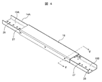
- FIG. 4 is an overall perspective view of the underfloor side beam according to the embodiment of the present invention
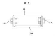
- FIG. 5 is a sectional view taken along line VV in FIG.
- the underfloor side beam 14A is formed by reinforcing a cross section cut in a direction orthogonal to the longitudinal direction in a U shape, and is arranged so that the upper side is the open side.
- a cross section cut in a direction orthogonal to the longitudinal direction is reinforced in a U shape, and the underfloor side beam reinforcing member 18 is arranged so that the lower side is the open side. Is provided.
- the width of the underfloor side beam reinforcing member 18 in the cross section cut in the direction orthogonal to the longitudinal direction is formed to be larger than the width of the underfloor side beam 14A.
- the underfloor side beam reinforcing member 18 and the underfloor side beam 14A are arranged so that their open sides face each other and the underfloor side beam 14A is inserted and fitted inside the underfloor side beam reinforcing member 18.
- the underfloor side beam reinforcing member 18 and the underfloor side beam 14A are opposed to each other by superimposing the inner side surface of the underfloor side beam reinforcing member 18 and the outer side surface of the underfloor side beam 14A, and the facing portions are fixed by bolts 36. Will be done.
- the underfloor side beam reinforcing member 18 is formed so that its longitudinal length is shorter than the longitudinal length of the underfloor side beam 14A, and is arranged at the center of the underfloor side beam 14A. Due to the difference in longitudinal length of the underfloor side beam 14A from the underfloor side beam reinforcing member 18, the floor of the car chamber 8 is provided at both ends not facing the underfloor side beam reinforcing member 18 via a vibration isolator 15 described in detail later. The area where is mounted is formed.
- the underfloor side beam 14A is reinforced by the underfloor side beam reinforcing member 18 having a simple fitting structure without significantly changing the external structure. Moreover, since the portion reinforced by the underfloor side beam reinforcing member 18 is mounted on the lower beam 10, the number of parts is small and the structure is relatively simple, so that the underfloor side beams 14A and 14B have sufficient strength. be able to.
- the other underfloor side beam 14B is also configured in the same manner as the above-mentioned underfloor side beam 14A.
- the longitudinal lengths of the underfloor side beams 14A and 14B are longer than those of the underfloor side beam reinforcing member 18, but when the underfloor side beams 14A and 14B are fixed on the lower beam 10, This is done using the portion reinforced by the underfloor side beam reinforcing member 18.
- vibration isolator mounting portions 19A and 19B are provided at both ends in the longitudinal direction not facing the underfloor side beam reinforcing member 18, respectively. It is formed.
- the vibration isolator mounting portions 19A and 19B correspond to the dotted line frame 40 shown by the dotted line in FIG. 2, and the vibration isolator 15 is configured in the same portion, and the floor of the car chamber 8 is provided via the vibration isolator 15. Is placed.
- the vibration isolator 15 is composed of, for example, an elastic body such as a coil spring or rubber.
- FIG. 6 is a partially enlarged view of the dotted line frame 40 of FIG.
- a reinforcing plate 20 that also serves as a panel is arranged at the bottom of the underfloor side beam 14B in the vibration isolator mounting portion 19B, and another reinforcing plate 22 corresponding to the reinforcing plate 20 is also provided on the lower surface side of the floor 21 of the car chamber 8. Have been placed.
- a plurality of vibration isolators 15 are interposed between the reinforcing plate 20 and the facing portion of the reinforcing plate 22, and the retaining bolts 23 are provided from the bottom of the underfloor side beam 14B and the holes 26 formed in the reinforcing plate 20.
- the adjusting jack bolt 25 is inserted into the bottom of the underfloor side beam 14B and the other holes 27 formed in the reinforcing plate 20, and vibration isolation is provided between the insertion side tip of the adjusting jack bolt 25 and the reinforcing plate 22.
- a gap G (gap) for adjusting the amount of deflection of the device 15 is formed.
- the adjusting jack bolt 25 is rotated so that the gap G becomes smaller, the tip of the adjusting jack bolt 25 on the insertion side is brought into contact with the reinforcing plate 22, and the adjustment is further performed.
- the jack bolt 25 is rotated to release the contact state between the reinforcing plate 22 and the vibration isolator 15. Since the car 3 is lifted by the adjusting jack bolt 25, the vibration isolator 15 used in this state is removed, and a new vibration isolator 15 is installed.
- the adjusting jack bolt 25 is rotated in the opposite direction to a position where the insertion side tip of the adjusting jack bolt 25 and the reinforcing plate 22 have a predetermined gap G, so that the reinforcing plate 22 and the vibration isolator 15 are brought into contact with each other.
- underfloor side beam 14A side has the same configuration.
- the upper beam 9 arranged at the upper part, the pair of standing frames 11A and 11B in which the upper ends thereof are connected to both ends in the longitudinal direction of the upper beam 9, and the pair of standing frames 11A and 11B.
- a pair of lower beams 10 arranged between the lower ends of the frames 11A and 11B and having both ends connected to each other, and a pair of lower beams 10 placed on both ends of the lower beams 10 and extending in a direction orthogonal to the lower beams 10.
- the underfloor side beams 14A and 14B are provided.
- a car chamber 8 is arranged in a portion surrounded by the upper beam 9, a pair of vertical frames 11A and 11B, and a lower beam 10, and the car chamber 8 is placed on the pair of underfloor side beams 14A and 14B.
- the pair of underfloor side beams 14A and 14B are provided with underfloor side beam reinforcing members 18 for reinforcing each of the pair of underfloor side beams 14A and 14B.
- the underfloor side beam reinforcing member 18 is arranged at least near the center of the underfloor side beams 14A and 14B.
- the underfloor side beam 14A and 14B can be reinforced by the underfloor side beam reinforcing member 18 without significantly changing the structure, and the stress is applied most in a simple configuration with a small number of parts.
- the cross-sectional rigidity near the central part can be sufficiently increased.
- the pair of underfloor side beams 14A and 14B are arranged so that the cross section cut in the direction orthogonal to the longitudinal direction is formed in a U shape and the upper side is the open side. ing.
- the underfloor side beam reinforcing member 18 has a U-shaped cross section cut in a direction orthogonal to the longitudinal direction, and is arranged with the lower side facing the upper opening of the pair of underfloor side beams 14A and 14B. I tried to do it.
- the open portions of the underfloor side beams 14A and 14B having a U-shaped cross section and the underfloor side beam reinforcing member 18 having a U-shaped cross section are arranged so as to face each other.
- 14B cross-sectional rigidity can be further increased.
- each of the pair of underfloor side beams 14A and 14B is formed to have a length in the longitudinal direction longer than the length in the longitudinal direction of the underfloor side beam reinforcing member 18, to reinforce the underfloor side beams.
- Anti-vibration devices are provided at both ends of the pair of underfloor side beams 14A and 14B that do not face the member 18.
- the car chamber 8 is placed on the pair of underfloor side beams 14A and 14B via the vibration isolator 15.
- the vibration isolator 15 can be installed after increasing the cross-sectional rigidity of the underfloor side beams 14A and 14B, and it is possible to provide the car 3 in which vibration is suppressed.
- a reinforcing plate 22 is arranged on the lower surface side of the car chamber 8, and holes 27 formed at the bottoms of the pair of underfloor side beam 14A and 14B are used for adjustment.
- the jack bolt 25 is inserted.
- the amount of deflection of the vibration isolator 15 can be easily adjusted by adjusting the gap between the adjusting jack bolt 25 and the reinforcing plate 22. Further, by adjusting the gap between the adjusting jack bolt 25 and the reinforcing plate 22, the vibration isolator 15 can be easily removed or attached.
- the present invention is not limited to the above-mentioned examples, and includes various modifications.
- the above-described embodiment has been described in detail in order to explain the present invention in an easy-to-understand manner, and is not necessarily limited to the one including all the described configurations. It is also possible to replace a part of the configuration of one embodiment with the configuration of another embodiment, and it is also possible to add the configuration of another embodiment to the configuration of one embodiment. In addition, it is possible to add, delete, or replace a part of the configuration of each embodiment with another configuration.
Landscapes
- Engineering & Computer Science (AREA)
- Civil Engineering (AREA)
- Mechanical Engineering (AREA)
- Structural Engineering (AREA)
- Physics & Mathematics (AREA)
- Fluid Mechanics (AREA)
- Cage And Drive Apparatuses For Elevators (AREA)
- Types And Forms Of Lifts (AREA)
- Elevator Control (AREA)
Priority Applications (6)
| Application Number | Priority Date | Filing Date | Title |
|---|---|---|---|
| JP2021514763A JP7214847B2 (ja) | 2019-04-19 | 2019-04-19 | エレベーター乗りかご、及びこの乗りかごを備えたエレベーター |
| US17/604,129 US12344506B2 (en) | 2019-04-19 | 2019-04-19 | Elevator passenger car and elevator having same car |
| EP19925437.6A EP3957591B1 (en) | 2019-04-19 | 2019-04-19 | Elevator passenger car and elevator having same car |
| CN201980095540.3A CN113727933B (zh) | 2019-04-19 | 2019-04-19 | 电梯轿厢以及具备该轿厢的电梯 |
| PCT/JP2019/016736 WO2020213147A1 (ja) | 2019-04-19 | 2019-04-19 | エレベーター乗りかご、及びこの乗りかごを備えたエレベーター |
| TW109112786A TWI772780B (zh) | 2019-04-19 | 2020-04-16 | 電梯車廂及具備該車廂的電梯 |
Applications Claiming Priority (1)
| Application Number | Priority Date | Filing Date | Title |
|---|---|---|---|
| PCT/JP2019/016736 WO2020213147A1 (ja) | 2019-04-19 | 2019-04-19 | エレベーター乗りかご、及びこの乗りかごを備えたエレベーター |
Publications (1)
| Publication Number | Publication Date |
|---|---|
| WO2020213147A1 true WO2020213147A1 (ja) | 2020-10-22 |
Family
ID=72837113
Family Applications (1)
| Application Number | Title | Priority Date | Filing Date |
|---|---|---|---|
| PCT/JP2019/016736 Ceased WO2020213147A1 (ja) | 2019-04-19 | 2019-04-19 | エレベーター乗りかご、及びこの乗りかごを備えたエレベーター |
Country Status (6)
| Country | Link |
|---|---|
| US (1) | US12344506B2 (https=) |
| EP (1) | EP3957591B1 (https=) |
| JP (1) | JP7214847B2 (https=) |
| CN (1) | CN113727933B (https=) |
| TW (1) | TWI772780B (https=) |
| WO (1) | WO2020213147A1 (https=) |
Cited By (3)
| Publication number | Priority date | Publication date | Assignee | Title |
|---|---|---|---|---|
| WO2023021645A1 (ja) * | 2021-08-19 | 2023-02-23 | 株式会社日立製作所 | 乗りかご及びエレベーター |
| JPWO2023021644A1 (https=) * | 2021-08-19 | 2023-02-23 | ||
| JPWO2023223405A1 (https=) * | 2022-05-17 | 2023-11-23 |
Families Citing this family (2)
| Publication number | Priority date | Publication date | Assignee | Title |
|---|---|---|---|---|
| CN115303918B (zh) * | 2022-09-19 | 2024-05-31 | 浙江恒达富士电梯工程有限公司 | 一种电梯上梁组件 |
| WO2024094915A1 (en) * | 2022-11-03 | 2024-05-10 | Kone Corporation | Elevator car and elevator |
Citations (5)
| Publication number | Priority date | Publication date | Assignee | Title |
|---|---|---|---|---|
| JPS5617412Y2 (https=) * | 1976-11-25 | 1981-04-23 | ||
| JPS5946970U (ja) * | 1982-09-22 | 1984-03-28 | 株式会社東芝 | エレベ−タのかご枠 |
| JP2012006695A (ja) | 2010-06-23 | 2012-01-12 | Toshiba Elevator Co Ltd | エレベータ乗りかごおよびエレベータ |
| WO2012028597A1 (de) * | 2010-09-01 | 2012-03-08 | Inventio Ag | Tragrahmen mit dämpfungselementen zur lagerung einer aufzugskabine |
| WO2015045097A1 (ja) * | 2013-09-27 | 2015-04-02 | 三菱電機株式会社 | エレベータのかご |
Family Cites Families (25)
| Publication number | Priority date | Publication date | Assignee | Title |
|---|---|---|---|---|
| US4249640A (en) * | 1979-05-02 | 1981-02-10 | Westinghouse Electric Corp. | Corner post platform assembly |
| US4361208A (en) * | 1980-12-22 | 1982-11-30 | Westinghouse Electric Corp. | Modular elevator car |
| US4700809A (en) * | 1986-04-18 | 1987-10-20 | Otis Elevator Company | Screwless elevator car assembly |
| US4899852A (en) * | 1988-11-03 | 1990-02-13 | Otis Elevator Company | Elevator car mounting assembly |
| FR2647097B1 (fr) * | 1989-05-17 | 1991-08-30 | Otis Elevator Co | Chassis support pour cabine d'ascenseur |
| KR950008262A (ko) | 1993-09-20 | 1995-04-17 | 가나이 쯔도무 | 철도차량 및 그 내부의장방법 |
| JPH08192972A (ja) * | 1995-01-17 | 1996-07-30 | Mitsubishi Electric Corp | エレベーターかご |
| JPH09110340A (ja) * | 1995-10-16 | 1997-04-28 | Hitachi Ltd | エレベーターのかご |
| PL190479B1 (pl) * | 1997-03-06 | 2005-12-30 | Inventio Ag | Kabina dźwigowa |
| SG74736A1 (en) * | 1998-07-13 | 2000-08-22 | Inventio Ag | Car structure |
| JP2004083146A (ja) * | 2002-08-23 | 2004-03-18 | Otis Elevator Co | エレベータのかご |
| JP5105512B2 (ja) * | 2007-05-21 | 2012-12-26 | 東芝エレベータ株式会社 | エレベーターのシーブ支持装置 |
| JP2009220893A (ja) * | 2008-03-13 | 2009-10-01 | Toshiba Elevator Co Ltd | エレベータのかご枠 |
| JP5411931B2 (ja) * | 2008-06-17 | 2014-02-12 | オーチス エレベータ カンパニー | つり下げ式エレベータかご構造 |
| CN201309788Y (zh) * | 2008-10-24 | 2009-09-16 | 宁波宏大电梯有限公司 | 电梯轿架结构 |
| JP2012166872A (ja) | 2011-02-10 | 2012-09-06 | Mitsubishi Electric Corp | エレベーターの乗りかご |
| JP5963530B2 (ja) * | 2012-05-11 | 2016-08-03 | 三菱電機株式会社 | エレベータのかご |
| DE112013007291T5 (de) * | 2013-08-02 | 2016-04-21 | Mitsubishi Electric Corporation | Unterbauaufzug |
| CN103708326A (zh) | 2013-12-17 | 2014-04-09 | 康力电梯股份有限公司 | 一种电梯轿厢架 |
| WO2016135855A1 (ja) * | 2015-02-24 | 2016-09-01 | 三菱電機株式会社 | エレベータ |
| CN105329758B (zh) * | 2015-12-16 | 2018-09-21 | 浙江巨人控股有限公司 | 一种活络轿底轿厢 |
| CN107416651B (zh) * | 2017-08-17 | 2023-07-07 | 宁波甘纳楼宇设备有限公司 | 一种集成多功能部件的紧凑型背包架轿底托 |
| CN107673173B (zh) * | 2017-09-27 | 2020-08-25 | 浙江巨人机电有限公司 | 一种家用电梯轿架结构 |
| CN108840198B (zh) * | 2018-08-09 | 2024-01-23 | 辛格林电梯有限公司 | 一种超高速电梯 |
| CN108821072B (zh) * | 2018-08-20 | 2023-12-26 | 迅达(中国)电梯有限公司 | 电梯轿厢的底部支撑框架 |
-
2019
- 2019-04-19 US US17/604,129 patent/US12344506B2/en active Active
- 2019-04-19 WO PCT/JP2019/016736 patent/WO2020213147A1/ja not_active Ceased
- 2019-04-19 JP JP2021514763A patent/JP7214847B2/ja active Active
- 2019-04-19 CN CN201980095540.3A patent/CN113727933B/zh active Active
- 2019-04-19 EP EP19925437.6A patent/EP3957591B1/en active Active
-
2020
- 2020-04-16 TW TW109112786A patent/TWI772780B/zh active
Patent Citations (5)
| Publication number | Priority date | Publication date | Assignee | Title |
|---|---|---|---|---|
| JPS5617412Y2 (https=) * | 1976-11-25 | 1981-04-23 | ||
| JPS5946970U (ja) * | 1982-09-22 | 1984-03-28 | 株式会社東芝 | エレベ−タのかご枠 |
| JP2012006695A (ja) | 2010-06-23 | 2012-01-12 | Toshiba Elevator Co Ltd | エレベータ乗りかごおよびエレベータ |
| WO2012028597A1 (de) * | 2010-09-01 | 2012-03-08 | Inventio Ag | Tragrahmen mit dämpfungselementen zur lagerung einer aufzugskabine |
| WO2015045097A1 (ja) * | 2013-09-27 | 2015-04-02 | 三菱電機株式会社 | エレベータのかご |
Non-Patent Citations (1)
| Title |
|---|
| See also references of EP3957591A4 |
Cited By (10)
| Publication number | Priority date | Publication date | Assignee | Title |
|---|---|---|---|---|
| WO2023021645A1 (ja) * | 2021-08-19 | 2023-02-23 | 株式会社日立製作所 | 乗りかご及びエレベーター |
| JPWO2023021645A1 (https=) * | 2021-08-19 | 2023-02-23 | ||
| JPWO2023021644A1 (https=) * | 2021-08-19 | 2023-02-23 | ||
| WO2023021644A1 (ja) * | 2021-08-19 | 2023-02-23 | 株式会社日立製作所 | 乗りかごおよびエレベーター |
| CN117794840A (zh) * | 2021-08-19 | 2024-03-29 | 株式会社日立制作所 | 电梯轿厢和电梯 |
| JP7531722B2 (ja) | 2021-08-19 | 2024-08-09 | 株式会社日立製作所 | 乗りかごおよびエレベーター |
| JP7614372B2 (ja) | 2021-08-19 | 2025-01-15 | 株式会社日立製作所 | 乗りかご及びエレベーター |
| US12509330B2 (en) | 2021-08-19 | 2025-12-30 | Hitachi, Ltd. | Elevator car and elevator |
| JPWO2023223405A1 (https=) * | 2022-05-17 | 2023-11-23 | ||
| JP7833032B2 (ja) | 2022-05-17 | 2026-03-18 | 株式会社日立製作所 | エレベーター |
Also Published As
| Publication number | Publication date |
|---|---|
| EP3957591A1 (en) | 2022-02-23 |
| TWI772780B (zh) | 2022-08-01 |
| JP7214847B2 (ja) | 2023-01-30 |
| EP3957591B1 (en) | 2024-11-13 |
| CN113727933A (zh) | 2021-11-30 |
| TW202039352A (zh) | 2020-11-01 |
| CN113727933B (zh) | 2023-04-11 |
| US20220227602A1 (en) | 2022-07-21 |
| EP3957591A4 (en) | 2022-11-23 |
| JPWO2020213147A1 (https=) | 2020-10-22 |
| US12344506B2 (en) | 2025-07-01 |
Similar Documents
| Publication | Publication Date | Title |
|---|---|---|
| WO2020213147A1 (ja) | エレベーター乗りかご、及びこの乗りかごを備えたエレベーター | |
| JP6058149B2 (ja) | エレベータのかご | |
| JP4726295B2 (ja) | エレベータ | |
| JP2008290828A (ja) | エレベーター装置 | |
| JP2008285282A (ja) | エレベータのかご | |
| JP2006264862A (ja) | マシンルームレスエレベータ | |
| JP4762210B2 (ja) | エレベータ | |
| KR100860935B1 (ko) | 기계실이 없는 엘리베이터 시스템 | |
| JP6692514B1 (ja) | かご吊り車組立体 | |
| JP4825475B2 (ja) | エレベータのかご上シーブカバー支持構造 | |
| JP7531722B2 (ja) | 乗りかごおよびエレベーター | |
| JP7362922B2 (ja) | エレベーターの乗りかご | |
| JP2005231801A (ja) | エレベータの釣り合いおもり | |
| JP5612053B2 (ja) | エレベータのかご吊り構造 | |
| CN110577138B (zh) | 电梯及其曳引机 | |
| JP7614372B2 (ja) | 乗りかご及びエレベーター | |
| JP4528017B2 (ja) | エレベータの釣合いロープの制振装置 | |
| JP2012041174A (ja) | エレベータのかご | |
| KR102414241B1 (ko) | 엘리베이터 케이지의 진동저감장치 | |
| JP5681284B2 (ja) | エレベータ | |
| HK1107327B (en) | Machineroom-less elevator system and machine support assembly for machineroom-less elevator system | |
| JP2009190823A (ja) | エレベータ防振構造 | |
| JP2011020752A (ja) | エレベータの乗りかご構造 | |
| JP2001240347A (ja) | エレベータ | |
| KR19990073749A (ko) | 엘리베이터의 로우프 제진장치 |
Legal Events
| Date | Code | Title | Description |
|---|---|---|---|
| 121 | Ep: the epo has been informed by wipo that ep was designated in this application |
Ref document number: 19925437 Country of ref document: EP Kind code of ref document: A1 |
|
| ENP | Entry into the national phase |
Ref document number: 2021514763 Country of ref document: JP Kind code of ref document: A |
|
| NENP | Non-entry into the national phase |
Ref country code: DE |
|
| WWE | Wipo information: entry into national phase |
Ref document number: 2019925437 Country of ref document: EP |
|
| WWG | Wipo information: grant in national office |
Ref document number: 17604129 Country of ref document: US |