EP3957591B1 - Elevator passenger car and elevator having same car - Google Patents
Elevator passenger car and elevator having same car Download PDFInfo
- Publication number
- EP3957591B1 EP3957591B1 EP19925437.6A EP19925437A EP3957591B1 EP 3957591 B1 EP3957591 B1 EP 3957591B1 EP 19925437 A EP19925437 A EP 19925437A EP 3957591 B1 EP3957591 B1 EP 3957591B1
- Authority
- EP
- European Patent Office
- Prior art keywords
- pair
- underfloor side
- underfloor
- car
- beams
- Prior art date
- Legal status (The legal status is an assumption and is not a legal conclusion. Google has not performed a legal analysis and makes no representation as to the accuracy of the status listed.)
- Active
Links
Images


Classifications
-
- B—PERFORMING OPERATIONS; TRANSPORTING
- B66—HOISTING; LIFTING; HAULING
- B66B—ELEVATORS; ESCALATORS OR MOVING WALKWAYS
- B66B11/00—Main component parts of lifts in, or associated with, buildings or other structures
- B66B11/02—Cages, i.e. cars
- B66B11/0206—Car frames
-
- B—PERFORMING OPERATIONS; TRANSPORTING
- B66—HOISTING; LIFTING; HAULING
- B66B—ELEVATORS; ESCALATORS OR MOVING WALKWAYS
- B66B11/00—Main component parts of lifts in, or associated with, buildings or other structures
- B66B11/02—Cages, i.e. cars
- B66B11/026—Attenuation system for shocks, vibrations, imbalance, e.g. passengers on the same side
- B66B11/0266—Passive systems
- B66B11/0273—Passive systems acting between car and supporting frame
Definitions
- the present invention relates to an elevator passenger car, and an elevator provided with the car.
- JP 2012006695A discloses the car frame constituted by a pair of vertical frames disposed parallel to a pair of guide rails, a lower beam which is provided with a pulley, and connected to lower sections of the pair of vertical frames while making the longitudinal direction horizontally oriented, and an upper beam which is connected to upper sections of the pair of vertical frames while making the longitudinal direction horizontally oriented.
- the pair of under-car frames fabricated by L-shaped steel is disposed on the upper surface of the lower beam in the direction orthogonal to the longitudinal direction of the lower beam.
- the pair of under-car frames is connected to a pair of support frames which is disposed in the direction orthogonal to the longitudinal direction of the pair of under-car frames.
- the pair of under-car frames serves to support a car room.
- WO 2015/045097 A1 discloses an elevator car according to the preamble of independent claim 1 that is configured in such a manner that a car frame has a left and right pair of car floor support frames for supporting the car chamber.
- the elevator passenger car as disclosed in JP 2012-6695 had a disadvantage of insufficient rigidity of the pair of under-car frames for supporting the car room. It was therefore required to connect the pair of under-car frames to the pair of support frames disposed in the direction orthogonal to the longitudinal direction of the pair of under-car frames, resulting in the complicated configuration.
- An object of the present invention is to provide an elevator passenger car, which allows enhancement of rigidity of the lower beam with the simple configuration while suppressing an increase in the number of components, and an elevator provided with the passenger car.
- the present invention provides an elevator passenger car as defined in claim 1.
- the present invention provides the elevator passenger car which allows enhancement of rigidity of the lower beam with the simple configuration while suppressing an increase in the number of components, and the elevator provided with the passenger car.
- the single component may be constituted by multiple members.
- Each of the multiple components may be constituted by the single member.
- a specific component constitutes a part of another component.
- a part of a specific component may serve as a part of the other component.
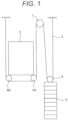
- FIG 1 schematically illustrates a structure of an elevator system according to an embodiment of the present invention.
- the elevator system is disposed in an unshown hoistway.
- One end of a main rope 2 wound around a hoisting machine 1 is suspended through under-car pulleys 4A, 4B disposed below a passenger car 3, and fixed to an upper position of the hoistway.
- the other end of the main rope 2 is suspended through a pulley 6 above a balance weight 5, and fixed to an upper position of the hoistway.
- the elevator system is configured to vertically move the passenger car 3 disposed at one side of the main rope, and the balance weight disposed at the other side of the main rope in the hoistway by rotatably driving the hoisting machine 1.
- Figure 2 is an enlarged side view of the passenger car 3 as illustrated in Figure 1 .
- directions of front-rear, up-down, and left-right are defined on the basis of a sight of a user of the elevator with respect to the passenger car 3 as illustrated in Figure 2 .
- the passenger car 3 includes a car frame 7 and a car room 8 that is formed inside the car frame 7.
- the car frame 7 includes an upper beam 9 disposed above the car room 8, a lower beam 10 disposed below the car room 8, and a pair of vertical frames 11A, 11B for connecting the respective ends of the upper beam 9 and the lower beam 10.
- the vertical frame 11A is not shown in the drawing as it is located at a back side of the car room 8.
- the car frame 7 is disposed closer to the front side from the center of the front-rear direction of the car room 8.
- the under-car pulleys 4A, 4B are positioned at the center of the car room 8 in the front-rear direction.
- Figure 3 is a perspective view only of the car frame as illustrated in Figure 2 .
- the car frame 7 is formed by connecting upper ends of the pair of vertical frames 11A, 11B to both longitudinal (left-right direction) ends of the upper beam 9 disposed at the upper side using bolts 31, and connecting lower ends of the pair of vertical frames 11A, 11B to both longitudinal (left-right direction) ends of the lower beam 10 disposed at the lower side using bolts 32.
- the lower beam 10 formed to have a U-like shape with an upper open section includes a mount part 10A having one upper end bent outward (front side), and a mount part 10B having the other upper end bent inward (front side).
- the car frame 7 is disposed along an unshown guide rail.
- An emergency stop device 12 disposed below the lower beam 10 applies braking force to the passenger car 3 via the guide rails when the speed of the passenger car 3 exceeds the predetermined fall speed so that the passenger car 3 is stopped.
- a guide device bracket 13 is disposed below the emergency stop device 12 for securing stability upon vertical movement of the passenger car 3 along the guide rail.
- a pair of underfloor side surface beams 14A, 14B is mounted on the mount parts 10A, 10B as upper parts of the lower beam 10, which will be described in detail later, and are fixed with bolts 33 ( Figure 2 ).
- a floor of the car room 8 is mounted on the underfloor side surface beams 14A, 14B at the part indicated by a dotted frame 40 of Figure 2 via antivibration devices 15.
- the underfloor side surface beams 14A, 14B are horizontally disposed inside the space defined by the opposing vertical frames 11A, 11B while extending in the front-rear direction orthogonally to the left-right direction (longitudinal direction) of the lower beam 10.
- Pulley brackets 16A, 16B are fixed to the lower surfaces of the underfloor side surface beams 14A, 14B with bolts 34, respectively.
- the under-car pulleys 4A, 4B are rotatably journaled to the pulley brackets 16A, 16B.
- a rope guide 17 is fixed with bolts 35 below the pulley brackets 16A, 16B so as to be connected to each other.
- the rope guide 17 is configured to prevent foreign matters from being caught in the main rope 2 wound around the under-car pulleys 4A, 4B.
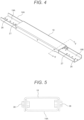
- Figure 4 is an overall perspective view of the underfloor side surface beam according to the embodiment of the present invention.
- Figure 5 is a sectional view taken along line V-V of Figure 4 .
- the underfloor side surface beam 14A has a U-shaped section cut in the direction orthogonal to the longitudinal direction, which is reinforced while having an upwardly directed open section.
- An underfloor side surface beam reinforcing member 18 has a U-shaped section cut in the direction orthogonal to the longitudinal direction reinforced while having a downwardly directed open section disposed opposingly to the upwardly directed open section of the underfloor side surface beam 14A.
- the underfloor side surface beam reinforcing member 18 is formed to have a width of the section cut orthogonally to the longitudinal direction larger than a width of the underfloor side surface beam 14A.
- the underfloor side surface beam reinforcing member 18 and the underfloor side surface beam 14A are arranged to have the respective open sections opposite to each other so that the underfloor side surface beam 14A is inserted to be fitted with the inside of the underfloor side surface beam reinforcing member 18.
- Each of the inner side surfaces of the underfloor side surface beam reinforcing member 18 and each of the outer side surfaces of the underfloor side surface beam 14A are opposingly joined and fixed with bolts 36.
- the underfloor side surface beam reinforcing member 18 is formed to have its longitudinal direction length shorter than that of the underfloor side surface beam 14A, and located in the center of the underfloor side surface beam 14A. Because of difference in the longitudinal direction length between the underfloor side surface beam 14A and the underfloor side surface beam reinforcing member 18, both ends each having no opposing section of the underfloor side surface beam reinforcing member 18 disposed above serve as areas on which the floor of the car room 8 is mounted via the antivibration devices 15 to be described in detail later.
- the underfloor side surface beam 14A is reinforced by the underfloor side surface beam reinforcing member 18 in the form of a simple fitting structure without largely changing the outer appearance configuration.
- the underfloor side surface beam is mounted on the lower beam 10 at the section reinforced by the underfloor side surface beam reinforcing member 18. Accordingly, it is possible to impart sufficient strength to both the underfloor side surface beams 14A, 14B using the relatively simple configuration with small number of components.
- the other underfloor side surface beam 14B is similarly configured to the underfloor side surface beam 14A as described above.
- each of the underfloor side surface beams 14A, 14B is longitudinally longer than the underfloor side surface beam reinforcing member 18, and fixed onto the lower beam 10 each at the section reinforced by the underfloor side surface beam reinforcing member 18.
- antivibration device mount sections 19A, 19B are formed on both longitudinal direction ends each having no opposing section of the underfloor side surface beam reinforcing member 18 disposed above.
- the antivibration devices 15 are disposed on the antivibration device mount sections 19A, 19B, on which the floor of the car room 8 is mounted via the antivibration devices 15.
- the antivibration device 15 is made of an elastic body such as a coil spring, rubber, and the like.
- Figure 6 is a partially enlarged view of the dotted frame of Figure 2 .
- a reinforcing plate 20 serving as a panel is disposed on the bottom of the underfloor side surface beam 14B at the antivibration device mount section 19B.
- Another reinforcing plate 22 corresponding to the reinforcing plate 20 is disposed below the lower surface of a floor 21 of the car room 8.
- the multiple antivibration devices 15 intervene between the opposing reinforcing plates 20 and 22.
- a stopper bolt 23 is inserted through a hole 26 formed in the bottom of the underfloor side surface beam 14B and the reinforcing plate 20.
- An adjusting jack bolt 25 is inserted into the other hole 27 formed in the bottom of the underfloor side surface beam 14B and the reinforcing plate 20.
- a gap G (opening) is formed between a leading end of the adjusting jack bolt 25 and the reinforcing plate 22 for adjusting a flexure amount of the antivibration device 15.
- the adjusting jack bolt 25 holds the space between the reinforcing plates 20 and 22 when the elevator is in operation so that the floor 21 of the car room 8 is supported with the antivibration devices 15. The vibration of the passenger car 3 thus can be absorbed by the antivibration device 15.
- the adjusting jack bolt 25 When replacing the antivibration device 15, the adjusting jack bolt 25 is rotated to reduce the gap G so that the leading end of the adjusting jack bolt 25 is brought into abutment on the reinforcing plate 22. The adjusting jack bolt 25 is further rotated to bring the reinforcing plate 22 and the antivibration device 15 into the non-contact state. In this state, the passenger car 3 is lifted by the adjusting jack bolt 25 so that the old antivibration device 15 which has been used in the state is replaced with a new antivibration device 15. Thereafter, the adjusting jack bolt 25 is rotated in reverse until the predetermined gap G between the leading end of the adjusting jack bolt 25 and the reinforcing plate 22 is restored to bring the reinforcing plate 22 into contact with the antivibration device 15.
- underfloor side surface beam 14A is also similarly configured.
- the embodiment includes the upper beam 9 disposed at an upper side, the pair of vertical frames 11A, 11B having upper ends connected to both ends of the upper beam 9 in a longitudinal direction, the lower beam 10 disposed between lower ends of the pair of vertical frames 11A, 11B while having both ends connected thereto, and the pair of underfloor side surface beams 14A, 14B which is mounted and connected onto the both ends of the lower beam 10 while extending in a direction orthogonal to the lower beam 10.
- the car room 8 is disposed at a part defined by the upper beam 9, the pair of vertical frames 11A, 11B, and the lower beam 10.
- the car room 8 is mounted on the pair of underfloor side surface beams 14A, 14B.
- the underfloor side surface beam reinforcing member 18 is provided for each of the pair of underfloor side surface beams 14A, 14B so as to be reinforced.
- the underfloor side surface beam reinforcing member 18 is located in at least each center of the underfloor side surface beams 14A, 14B.
- the structure allows the underfloor side surface beams 14A, 14B to be reinforced by the underfloor side surface beam reinforcing member 18 without largely changing the configuration.
- the section rigidity of an area around the center to which the stress is applied intensively can be sufficiently enhanced with the simple configuration with small number of components.
- the pair of underfloor side surface beams 14A, 14B has the U-shaped section cut in the direction orthogonal to the longitudinal direction, having an upwardly directed open section.
- the underfloor side surface beam reinforcing member 18 has the U-shaped section cut in the direction orthogonal to the longitudinal direction, having the downwardly directed open section to be opposite to each of the open sections of the pair of underfloor side surface beams 14A, 14B.
- the underfloor side surface beams 14A, 14B of U-shaped section, and the underfloor side surface beam reinforcing member 18 of U-shaped section are arranged to have the respective open sections are opposite to each other. This makes it possible to further enhance each section rigidity of the underfloor side surface beams 14A, 14B.
- each longitudinal direction length of the pair of underfloor side surface beams 14A, 14B is longer than the longitudinal direction length of the underfloor side surface beam reinforcing member 18.
- the antivibration devices are disposed on both ends of each of the pair of underfloor side surface beams 14A, 14B, each end having no opposing section of the underfloor side surface beam reinforcing member 18 disposed above for accommodating the car room 8 via the antivibration devices 15.
- the structure allows provision of the antivibration devices 15 to provide the passenger car 3 with less vibrations by enhancing each section rigidity of the underfloor side surface beams 14A, 14B.
- the reinforcing plate 22 is disposed below the lower surface of the car room 8.
- the adjusting jack bolt 25 is inserted into the hole 27 formed in each bottom at both ends of the pair of underfloor side surface beams 14A, 14B.
- the structure allows easy adjustment of the flexure amount of the antivibration device 15 by regulating the gap between the adjusting jack bolt 25 and the reinforcing plate 22. Furthermore, regulation of the gap between the adjusting jack bolt 25 and the reinforcing plate 22 allows easy detachment or attachment of the antivibration device 15.
Landscapes
- Engineering & Computer Science (AREA)
- Civil Engineering (AREA)
- Mechanical Engineering (AREA)
- Structural Engineering (AREA)
- Physics & Mathematics (AREA)
- Fluid Mechanics (AREA)
- Cage And Drive Apparatuses For Elevators (AREA)
- Types And Forms Of Lifts (AREA)
- Elevator Control (AREA)
Applications Claiming Priority (1)
| Application Number | Priority Date | Filing Date | Title |
|---|---|---|---|
| PCT/JP2019/016736 WO2020213147A1 (ja) | 2019-04-19 | 2019-04-19 | エレベーター乗りかご、及びこの乗りかごを備えたエレベーター |
Publications (3)
| Publication Number | Publication Date |
|---|---|
| EP3957591A1 EP3957591A1 (en) | 2022-02-23 |
| EP3957591A4 EP3957591A4 (en) | 2022-11-23 |
| EP3957591B1 true EP3957591B1 (en) | 2024-11-13 |
Family
ID=72837113
Family Applications (1)
| Application Number | Title | Priority Date | Filing Date |
|---|---|---|---|
| EP19925437.6A Active EP3957591B1 (en) | 2019-04-19 | 2019-04-19 | Elevator passenger car and elevator having same car |
Country Status (6)
| Country | Link |
|---|---|
| US (1) | US12344506B2 (https=) |
| EP (1) | EP3957591B1 (https=) |
| JP (1) | JP7214847B2 (https=) |
| CN (1) | CN113727933B (https=) |
| TW (1) | TWI772780B (https=) |
| WO (1) | WO2020213147A1 (https=) |
Families Citing this family (5)
| Publication number | Priority date | Publication date | Assignee | Title |
|---|---|---|---|---|
| WO2023021644A1 (ja) * | 2021-08-19 | 2023-02-23 | 株式会社日立製作所 | 乗りかごおよびエレベーター |
| WO2023021645A1 (ja) * | 2021-08-19 | 2023-02-23 | 株式会社日立製作所 | 乗りかご及びエレベーター |
| US20250353703A1 (en) * | 2022-05-17 | 2025-11-20 | Hitachi, Ltd. | Elevator |
| CN115303918B (zh) * | 2022-09-19 | 2024-05-31 | 浙江恒达富士电梯工程有限公司 | 一种电梯上梁组件 |
| WO2024094915A1 (en) * | 2022-11-03 | 2024-05-10 | Kone Corporation | Elevator car and elevator |
Family Cites Families (30)
| Publication number | Priority date | Publication date | Assignee | Title |
|---|---|---|---|---|
| JPS5617412Y2 (https=) * | 1976-11-25 | 1981-04-23 | ||
| US4249640A (en) * | 1979-05-02 | 1981-02-10 | Westinghouse Electric Corp. | Corner post platform assembly |
| US4361208A (en) * | 1980-12-22 | 1982-11-30 | Westinghouse Electric Corp. | Modular elevator car |
| JPS5946970U (ja) * | 1982-09-22 | 1984-03-28 | 株式会社東芝 | エレベ−タのかご枠 |
| US4700809A (en) * | 1986-04-18 | 1987-10-20 | Otis Elevator Company | Screwless elevator car assembly |
| US4899852A (en) * | 1988-11-03 | 1990-02-13 | Otis Elevator Company | Elevator car mounting assembly |
| FR2647097B1 (fr) * | 1989-05-17 | 1991-08-30 | Otis Elevator Co | Chassis support pour cabine d'ascenseur |
| KR950008262A (ko) | 1993-09-20 | 1995-04-17 | 가나이 쯔도무 | 철도차량 및 그 내부의장방법 |
| JPH08192972A (ja) * | 1995-01-17 | 1996-07-30 | Mitsubishi Electric Corp | エレベーターかご |
| JPH09110340A (ja) * | 1995-10-16 | 1997-04-28 | Hitachi Ltd | エレベーターのかご |
| PL190479B1 (pl) * | 1997-03-06 | 2005-12-30 | Inventio Ag | Kabina dźwigowa |
| SG74736A1 (en) * | 1998-07-13 | 2000-08-22 | Inventio Ag | Car structure |
| JP2004083146A (ja) * | 2002-08-23 | 2004-03-18 | Otis Elevator Co | エレベータのかご |
| JP5105512B2 (ja) * | 2007-05-21 | 2012-12-26 | 東芝エレベータ株式会社 | エレベーターのシーブ支持装置 |
| JP2009220893A (ja) * | 2008-03-13 | 2009-10-01 | Toshiba Elevator Co Ltd | エレベータのかご枠 |
| JP5411931B2 (ja) * | 2008-06-17 | 2014-02-12 | オーチス エレベータ カンパニー | つり下げ式エレベータかご構造 |
| CN201309788Y (zh) * | 2008-10-24 | 2009-09-16 | 宁波宏大电梯有限公司 | 电梯轿架结构 |
| JP2012006695A (ja) | 2010-06-23 | 2012-01-12 | Toshiba Elevator Co Ltd | エレベータ乗りかごおよびエレベータ |
| WO2012028597A1 (de) * | 2010-09-01 | 2012-03-08 | Inventio Ag | Tragrahmen mit dämpfungselementen zur lagerung einer aufzugskabine |
| JP2012166872A (ja) | 2011-02-10 | 2012-09-06 | Mitsubishi Electric Corp | エレベーターの乗りかご |
| JP5963530B2 (ja) * | 2012-05-11 | 2016-08-03 | 三菱電機株式会社 | エレベータのかご |
| DE112013007291T5 (de) * | 2013-08-02 | 2016-04-21 | Mitsubishi Electric Corporation | Unterbauaufzug |
| JP6058149B2 (ja) | 2013-09-27 | 2017-01-11 | 三菱電機株式会社 | エレベータのかご |
| CN103708326A (zh) | 2013-12-17 | 2014-04-09 | 康力电梯股份有限公司 | 一种电梯轿厢架 |
| WO2016135855A1 (ja) * | 2015-02-24 | 2016-09-01 | 三菱電機株式会社 | エレベータ |
| CN105329758B (zh) * | 2015-12-16 | 2018-09-21 | 浙江巨人控股有限公司 | 一种活络轿底轿厢 |
| CN107416651B (zh) * | 2017-08-17 | 2023-07-07 | 宁波甘纳楼宇设备有限公司 | 一种集成多功能部件的紧凑型背包架轿底托 |
| CN107673173B (zh) * | 2017-09-27 | 2020-08-25 | 浙江巨人机电有限公司 | 一种家用电梯轿架结构 |
| CN108840198B (zh) * | 2018-08-09 | 2024-01-23 | 辛格林电梯有限公司 | 一种超高速电梯 |
| CN108821072B (zh) * | 2018-08-20 | 2023-12-26 | 迅达(中国)电梯有限公司 | 电梯轿厢的底部支撑框架 |
-
2019
- 2019-04-19 US US17/604,129 patent/US12344506B2/en active Active
- 2019-04-19 WO PCT/JP2019/016736 patent/WO2020213147A1/ja not_active Ceased
- 2019-04-19 JP JP2021514763A patent/JP7214847B2/ja active Active
- 2019-04-19 CN CN201980095540.3A patent/CN113727933B/zh active Active
- 2019-04-19 EP EP19925437.6A patent/EP3957591B1/en active Active
-
2020
- 2020-04-16 TW TW109112786A patent/TWI772780B/zh active
Also Published As
| Publication number | Publication date |
|---|---|
| EP3957591A1 (en) | 2022-02-23 |
| TWI772780B (zh) | 2022-08-01 |
| JP7214847B2 (ja) | 2023-01-30 |
| WO2020213147A1 (ja) | 2020-10-22 |
| CN113727933A (zh) | 2021-11-30 |
| TW202039352A (zh) | 2020-11-01 |
| CN113727933B (zh) | 2023-04-11 |
| US20220227602A1 (en) | 2022-07-21 |
| EP3957591A4 (en) | 2022-11-23 |
| JPWO2020213147A1 (https=) | 2020-10-22 |
| US12344506B2 (en) | 2025-07-01 |
Similar Documents
| Publication | Publication Date | Title |
|---|---|---|
| EP3957591B1 (en) | Elevator passenger car and elevator having same car | |
| KR101226976B1 (ko) | 엘리베이터 기계 지지체 | |
| EP2914530B1 (en) | System including structurally independent elevator machine guiderail mounts | |
| US9272880B2 (en) | Elevator system including control electronics supported on an elevator machine support | |
| JP2008290828A (ja) | エレベーター装置 | |
| WO2015045097A1 (ja) | エレベータのかご | |
| EP4424626B1 (en) | Support apparatus for elevator drive assembly | |
| WO2006101154A1 (ja) | マシンルームレスエレベータ | |
| KR100860935B1 (ko) | 기계실이 없는 엘리베이터 시스템 | |
| JP5518318B2 (ja) | エレベータ用マシンビーム | |
| JP7614372B2 (ja) | 乗りかご及びエレベーター | |
| JP4322361B2 (ja) | 巻上機、エレベーター及びエレベーターにおける巻上機の振動騒音低減方法 | |
| JP7362922B2 (ja) | エレベーターの乗りかご | |
| JP2001335257A (ja) | ロープ式エレベータ | |
| JP4528017B2 (ja) | エレベータの釣合いロープの制振装置 | |
| JP7665004B1 (ja) | エレベーターのロープ取付装置 | |
| JP2013006636A (ja) | エレベータ装置 | |
| JP2567946B2 (ja) | 昇降機 | |
| JP2009190823A (ja) | エレベータ防振構造 | |
| JP5681284B2 (ja) | エレベータ | |
| JP2000118911A (ja) | エレベータ | |
| WO2013167929A1 (en) | Elevator car assembly | |
| JPH11139710A (ja) | エレベータの釣合いおもり | |
| JP2001240347A (ja) | エレベータ | |
| HK1107327B (en) | Machineroom-less elevator system and machine support assembly for machineroom-less elevator system |
Legal Events
| Date | Code | Title | Description |
|---|---|---|---|
| STAA | Information on the status of an ep patent application or granted ep patent |
Free format text: STATUS: THE INTERNATIONAL PUBLICATION HAS BEEN MADE |
|
| PUAI | Public reference made under article 153(3) epc to a published international application that has entered the european phase |
Free format text: ORIGINAL CODE: 0009012 |
|
| STAA | Information on the status of an ep patent application or granted ep patent |
Free format text: STATUS: REQUEST FOR EXAMINATION WAS MADE |
|
| 17P | Request for examination filed |
Effective date: 20211018 |
|
| AK | Designated contracting states |
Kind code of ref document: A1 Designated state(s): AL AT BE BG CH CY CZ DE DK EE ES FI FR GB GR HR HU IE IS IT LI LT LU LV MC MK MT NL NO PL PT RO RS SE SI SK SM TR |
|
| DAV | Request for validation of the european patent (deleted) | ||
| DAX | Request for extension of the european patent (deleted) | ||
| A4 | Supplementary search report drawn up and despatched |
Effective date: 20221020 |
|
| RIC1 | Information provided on ipc code assigned before grant |
Ipc: B66B 11/02 20060101AFI20221014BHEP |
|
| GRAP | Despatch of communication of intention to grant a patent |
Free format text: ORIGINAL CODE: EPIDOSNIGR1 |
|
| STAA | Information on the status of an ep patent application or granted ep patent |
Free format text: STATUS: GRANT OF PATENT IS INTENDED |
|
| INTG | Intention to grant announced |
Effective date: 20240703 |
|
| GRAS | Grant fee paid |
Free format text: ORIGINAL CODE: EPIDOSNIGR3 |
|
| GRAA | (expected) grant |
Free format text: ORIGINAL CODE: 0009210 |
|
| STAA | Information on the status of an ep patent application or granted ep patent |
Free format text: STATUS: THE PATENT HAS BEEN GRANTED |
|
| AK | Designated contracting states |
Kind code of ref document: B1 Designated state(s): AL AT BE BG CH CY CZ DE DK EE ES FI FR GB GR HR HU IE IS IT LI LT LU LV MC MK MT NL NO PL PT RO RS SE SI SK SM TR |
|
| REG | Reference to a national code |
Ref country code: GB Ref legal event code: FG4D |
|
| REG | Reference to a national code |
Ref country code: CH Ref legal event code: EP |
|
| REG | Reference to a national code |
Ref country code: IE Ref legal event code: FG4D |
|
| REG | Reference to a national code |
Ref country code: DE Ref legal event code: R096 Ref document number: 602019062094 Country of ref document: DE |
|
| REG | Reference to a national code |
Ref country code: LT Ref legal event code: MG9D |
|
| REG | Reference to a national code |
Ref country code: NL Ref legal event code: MP Effective date: 20241113 |
|
| PG25 | Lapsed in a contracting state [announced via postgrant information from national office to epo] |
Ref country code: IS Free format text: LAPSE BECAUSE OF FAILURE TO SUBMIT A TRANSLATION OF THE DESCRIPTION OR TO PAY THE FEE WITHIN THE PRESCRIBED TIME-LIMIT Effective date: 20250313 Ref country code: HR Free format text: LAPSE BECAUSE OF FAILURE TO SUBMIT A TRANSLATION OF THE DESCRIPTION OR TO PAY THE FEE WITHIN THE PRESCRIBED TIME-LIMIT Effective date: 20241113 Ref country code: PT Free format text: LAPSE BECAUSE OF FAILURE TO SUBMIT A TRANSLATION OF THE DESCRIPTION OR TO PAY THE FEE WITHIN THE PRESCRIBED TIME-LIMIT Effective date: 20250313 |
|
| PG25 | Lapsed in a contracting state [announced via postgrant information from national office to epo] |
Ref country code: NL Free format text: LAPSE BECAUSE OF FAILURE TO SUBMIT A TRANSLATION OF THE DESCRIPTION OR TO PAY THE FEE WITHIN THE PRESCRIBED TIME-LIMIT Effective date: 20241113 Ref country code: FI Free format text: LAPSE BECAUSE OF FAILURE TO SUBMIT A TRANSLATION OF THE DESCRIPTION OR TO PAY THE FEE WITHIN THE PRESCRIBED TIME-LIMIT Effective date: 20241113 |
|
| REG | Reference to a national code |
Ref country code: AT Ref legal event code: MK05 Ref document number: 1741572 Country of ref document: AT Kind code of ref document: T Effective date: 20241113 |
|
| PG25 | Lapsed in a contracting state [announced via postgrant information from national office to epo] |
Ref country code: BG Free format text: LAPSE BECAUSE OF FAILURE TO SUBMIT A TRANSLATION OF THE DESCRIPTION OR TO PAY THE FEE WITHIN THE PRESCRIBED TIME-LIMIT Effective date: 20241113 |
|
| PG25 | Lapsed in a contracting state [announced via postgrant information from national office to epo] |
Ref country code: ES Free format text: LAPSE BECAUSE OF FAILURE TO SUBMIT A TRANSLATION OF THE DESCRIPTION OR TO PAY THE FEE WITHIN THE PRESCRIBED TIME-LIMIT Effective date: 20241113 |
|
| PG25 | Lapsed in a contracting state [announced via postgrant information from national office to epo] |
Ref country code: NO Free format text: LAPSE BECAUSE OF FAILURE TO SUBMIT A TRANSLATION OF THE DESCRIPTION OR TO PAY THE FEE WITHIN THE PRESCRIBED TIME-LIMIT Effective date: 20250213 |
|
| PG25 | Lapsed in a contracting state [announced via postgrant information from national office to epo] |
Ref country code: LV Free format text: LAPSE BECAUSE OF FAILURE TO SUBMIT A TRANSLATION OF THE DESCRIPTION OR TO PAY THE FEE WITHIN THE PRESCRIBED TIME-LIMIT Effective date: 20241113 Ref country code: AT Free format text: LAPSE BECAUSE OF FAILURE TO SUBMIT A TRANSLATION OF THE DESCRIPTION OR TO PAY THE FEE WITHIN THE PRESCRIBED TIME-LIMIT Effective date: 20241113 Ref country code: GR Free format text: LAPSE BECAUSE OF FAILURE TO SUBMIT A TRANSLATION OF THE DESCRIPTION OR TO PAY THE FEE WITHIN THE PRESCRIBED TIME-LIMIT Effective date: 20250214 |
|
| PG25 | Lapsed in a contracting state [announced via postgrant information from national office to epo] |
Ref country code: PL Free format text: LAPSE BECAUSE OF FAILURE TO SUBMIT A TRANSLATION OF THE DESCRIPTION OR TO PAY THE FEE WITHIN THE PRESCRIBED TIME-LIMIT Effective date: 20241113 |
|
| PG25 | Lapsed in a contracting state [announced via postgrant information from national office to epo] |
Ref country code: RS Free format text: LAPSE BECAUSE OF FAILURE TO SUBMIT A TRANSLATION OF THE DESCRIPTION OR TO PAY THE FEE WITHIN THE PRESCRIBED TIME-LIMIT Effective date: 20250213 |
|
| PG25 | Lapsed in a contracting state [announced via postgrant information from national office to epo] |
Ref country code: SM Free format text: LAPSE BECAUSE OF FAILURE TO SUBMIT A TRANSLATION OF THE DESCRIPTION OR TO PAY THE FEE WITHIN THE PRESCRIBED TIME-LIMIT Effective date: 20241113 |
|
| PGFP | Annual fee paid to national office [announced via postgrant information from national office to epo] |
Ref country code: DE Payment date: 20250423 Year of fee payment: 7 |
|
| PG25 | Lapsed in a contracting state [announced via postgrant information from national office to epo] |
Ref country code: DK Free format text: LAPSE BECAUSE OF FAILURE TO SUBMIT A TRANSLATION OF THE DESCRIPTION OR TO PAY THE FEE WITHIN THE PRESCRIBED TIME-LIMIT Effective date: 20241113 |
|
| PG25 | Lapsed in a contracting state [announced via postgrant information from national office to epo] |
Ref country code: EE Free format text: LAPSE BECAUSE OF FAILURE TO SUBMIT A TRANSLATION OF THE DESCRIPTION OR TO PAY THE FEE WITHIN THE PRESCRIBED TIME-LIMIT Effective date: 20241113 |
|
| PGFP | Annual fee paid to national office [announced via postgrant information from national office to epo] |
Ref country code: FR Payment date: 20250423 Year of fee payment: 7 |
|
| PG25 | Lapsed in a contracting state [announced via postgrant information from national office to epo] |
Ref country code: RO Free format text: LAPSE BECAUSE OF FAILURE TO SUBMIT A TRANSLATION OF THE DESCRIPTION OR TO PAY THE FEE WITHIN THE PRESCRIBED TIME-LIMIT Effective date: 20241113 |
|
| PG25 | Lapsed in a contracting state [announced via postgrant information from national office to epo] |
Ref country code: SK Free format text: LAPSE BECAUSE OF FAILURE TO SUBMIT A TRANSLATION OF THE DESCRIPTION OR TO PAY THE FEE WITHIN THE PRESCRIBED TIME-LIMIT Effective date: 20241113 |
|
| PG25 | Lapsed in a contracting state [announced via postgrant information from national office to epo] |
Ref country code: CZ Free format text: LAPSE BECAUSE OF FAILURE TO SUBMIT A TRANSLATION OF THE DESCRIPTION OR TO PAY THE FEE WITHIN THE PRESCRIBED TIME-LIMIT Effective date: 20241113 |
|
| PG25 | Lapsed in a contracting state [announced via postgrant information from national office to epo] |
Ref country code: IT Free format text: LAPSE BECAUSE OF FAILURE TO SUBMIT A TRANSLATION OF THE DESCRIPTION OR TO PAY THE FEE WITHIN THE PRESCRIBED TIME-LIMIT Effective date: 20241113 |
|
| REG | Reference to a national code |
Ref country code: DE Ref legal event code: R097 Ref document number: 602019062094 Country of ref document: DE |
|
| PG25 | Lapsed in a contracting state [announced via postgrant information from national office to epo] |
Ref country code: SE Free format text: LAPSE BECAUSE OF FAILURE TO SUBMIT A TRANSLATION OF THE DESCRIPTION OR TO PAY THE FEE WITHIN THE PRESCRIBED TIME-LIMIT Effective date: 20241113 |
|
| PLBE | No opposition filed within time limit |
Free format text: ORIGINAL CODE: 0009261 |
|
| STAA | Information on the status of an ep patent application or granted ep patent |
Free format text: STATUS: NO OPPOSITION FILED WITHIN TIME LIMIT |
|
| 26N | No opposition filed |
Effective date: 20250814 |
|
| REG | Reference to a national code |
Ref country code: CH Ref legal event code: H13 Free format text: ST27 STATUS EVENT CODE: U-0-0-H10-H13 (AS PROVIDED BY THE NATIONAL OFFICE) Effective date: 20251125 |
|
| PG25 | Lapsed in a contracting state [announced via postgrant information from national office to epo] |
Ref country code: LU Free format text: LAPSE BECAUSE OF NON-PAYMENT OF DUE FEES Effective date: 20250419 |
|
| PG25 | Lapsed in a contracting state [announced via postgrant information from national office to epo] |
Ref country code: MC Free format text: LAPSE BECAUSE OF FAILURE TO SUBMIT A TRANSLATION OF THE DESCRIPTION OR TO PAY THE FEE WITHIN THE PRESCRIBED TIME-LIMIT Effective date: 20241113 |
|
| GBPC | Gb: european patent ceased through non-payment of renewal fee |
Effective date: 20250419 |
|
| REG | Reference to a national code |
Ref country code: BE Ref legal event code: MM Effective date: 20250430 |
|
| PG25 | Lapsed in a contracting state [announced via postgrant information from national office to epo] |
Ref country code: GB Free format text: LAPSE BECAUSE OF NON-PAYMENT OF DUE FEES Effective date: 20250419 |
|
| PG25 | Lapsed in a contracting state [announced via postgrant information from national office to epo] |
Ref country code: BE Free format text: LAPSE BECAUSE OF NON-PAYMENT OF DUE FEES Effective date: 20250430 |
|
| PG25 | Lapsed in a contracting state [announced via postgrant information from national office to epo] |
Ref country code: CH Free format text: LAPSE BECAUSE OF NON-PAYMENT OF DUE FEES Effective date: 20250430 |
|
| PG25 | Lapsed in a contracting state [announced via postgrant information from national office to epo] |
Ref country code: IE Free format text: LAPSE BECAUSE OF NON-PAYMENT OF DUE FEES Effective date: 20250419 |