WO2020195011A1 - 緩衝器 - Google Patents
緩衝器 Download PDFInfo
- Publication number
- WO2020195011A1 WO2020195011A1 PCT/JP2020/000676 JP2020000676W WO2020195011A1 WO 2020195011 A1 WO2020195011 A1 WO 2020195011A1 JP 2020000676 W JP2020000676 W JP 2020000676W WO 2020195011 A1 WO2020195011 A1 WO 2020195011A1
- Authority
- WO
- WIPO (PCT)
- Prior art keywords
- passage
- valve
- disc
- chamber
- piston
- Prior art date
- Legal status (The legal status is an assumption and is not a legal conclusion. Google has not performed a legal analysis and makes no representation as to the accuracy of the status listed.)
- Ceased
Links
Images



Classifications
-
- F—MECHANICAL ENGINEERING; LIGHTING; HEATING; WEAPONS; BLASTING
- F16—ENGINEERING ELEMENTS AND UNITS; GENERAL MEASURES FOR PRODUCING AND MAINTAINING EFFECTIVE FUNCTIONING OF MACHINES OR INSTALLATIONS; THERMAL INSULATION IN GENERAL
- F16F—SPRINGS; SHOCK-ABSORBERS; MEANS FOR DAMPING VIBRATION
- F16F9/00—Springs, vibration-dampers, shock-absorbers, or similarly-constructed movement-dampers using a fluid or the equivalent as damping medium
- F16F9/32—Details
- F16F9/34—Special valve constructions; Shape or construction of throttling passages
- F16F9/348—Throttling passages in the form of annular discs or other plate-like elements which may or may not have a spring action, operating in opposite directions or singly, e.g. annular discs positioned on top of the valve or piston body
- F16F9/3482—Throttling passages in the form of annular discs or other plate-like elements which may or may not have a spring action, operating in opposite directions or singly, e.g. annular discs positioned on top of the valve or piston body the annular discs being incorporated within the valve or piston body
-
- F—MECHANICAL ENGINEERING; LIGHTING; HEATING; WEAPONS; BLASTING
- F16—ENGINEERING ELEMENTS AND UNITS; GENERAL MEASURES FOR PRODUCING AND MAINTAINING EFFECTIVE FUNCTIONING OF MACHINES OR INSTALLATIONS; THERMAL INSULATION IN GENERAL
- F16F—SPRINGS; SHOCK-ABSORBERS; MEANS FOR DAMPING VIBRATION
- F16F9/00—Springs, vibration-dampers, shock-absorbers, or similarly-constructed movement-dampers using a fluid or the equivalent as damping medium
- F16F9/06—Springs, vibration-dampers, shock-absorbers, or similarly-constructed movement-dampers using a fluid or the equivalent as damping medium using both gas and liquid
- F16F9/062—Bi-tubular units
-
- F—MECHANICAL ENGINEERING; LIGHTING; HEATING; WEAPONS; BLASTING
- F16—ENGINEERING ELEMENTS AND UNITS; GENERAL MEASURES FOR PRODUCING AND MAINTAINING EFFECTIVE FUNCTIONING OF MACHINES OR INSTALLATIONS; THERMAL INSULATION IN GENERAL
- F16F—SPRINGS; SHOCK-ABSORBERS; MEANS FOR DAMPING VIBRATION
- F16F9/00—Springs, vibration-dampers, shock-absorbers, or similarly-constructed movement-dampers using a fluid or the equivalent as damping medium
- F16F9/10—Springs, vibration-dampers, shock-absorbers, or similarly-constructed movement-dampers using a fluid or the equivalent as damping medium using liquid only; using a fluid of which the nature is immaterial
- F16F9/14—Devices with one or more members, e.g. pistons, vanes, moving to and fro in chambers and using throttling effect
- F16F9/16—Devices with one or more members, e.g. pistons, vanes, moving to and fro in chambers and using throttling effect involving only straight-line movement of the effective parts
- F16F9/18—Devices with one or more members, e.g. pistons, vanes, moving to and fro in chambers and using throttling effect involving only straight-line movement of the effective parts with a closed cylinder and a piston separating two or more working spaces therein
-
- F—MECHANICAL ENGINEERING; LIGHTING; HEATING; WEAPONS; BLASTING
- F16—ENGINEERING ELEMENTS AND UNITS; GENERAL MEASURES FOR PRODUCING AND MAINTAINING EFFECTIVE FUNCTIONING OF MACHINES OR INSTALLATIONS; THERMAL INSULATION IN GENERAL
- F16F—SPRINGS; SHOCK-ABSORBERS; MEANS FOR DAMPING VIBRATION
- F16F9/00—Springs, vibration-dampers, shock-absorbers, or similarly-constructed movement-dampers using a fluid or the equivalent as damping medium
- F16F9/32—Details
- F16F9/34—Special valve constructions; Shape or construction of throttling passages
- F16F9/348—Throttling passages in the form of annular discs or other plate-like elements which may or may not have a spring action, operating in opposite directions or singly, e.g. annular discs positioned on top of the valve or piston body
- F16F9/3484—Throttling passages in the form of annular discs or other plate-like elements which may or may not have a spring action, operating in opposite directions or singly, e.g. annular discs positioned on top of the valve or piston body characterised by features of the annular discs per se, singularly or in combination
Definitions
- the present invention relates to a shock absorber.
- the present application claims priority based on Japanese Patent Application No. 2019-059207 filed in Japan on March 26, 2019, the contents of which are incorporated herein by reference.
- a shock absorber having two valves that open in the same stroke is disclosed (see, for example, Patent Documents 1 to 3).
- the structure of the shock absorber is required to be simplified.
- an object of the present invention is to provide a shock absorber capable of simplifying the structure.
- One aspect of the shock absorber of the present invention is provided in a first passage formed in a piston, and a first damping force generating mechanism for generating a damping force and a piston rod are inserted and arranged on one chamber side.
- the first passage has a second damping force generating mechanism provided in a second passage parallel to the first passage to generate a damping force
- the second damping force generating mechanism has a bottomed cylinder having a cylinder portion and a bottom portion.
- An annular first valve seat formed on the tubular portion of the case member, and an annular disc valve on which the outer peripheral side detachable portion is detachably arranged on the first valve seat of the case member.
- the second passage is provided with a second valve seat provided on the side of the disc valve opposite to the first valve seat and supporting the disc valve so as to be separably inside in the radial direction from the disengagement portion.
- a chamber passage portion that communicates with a piston rod passage portion formed by notching or penetrating the piston rod and a case inner chamber between the piston rod passage portion and the bottom portion of the case member and the disc valve.
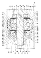
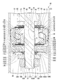
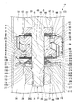
- FIGS. 1 to 8 The first embodiment according to the present invention will be described with reference to FIGS. 1 to 8.
- the upper side in FIGS. 1 to 3 and 9 to 13 will be referred to as “upper”, and the lower side in FIGS. 1 to 3 and 9 to 13 will be referred to as “lower”. ..
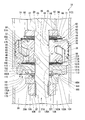
- the shock absorber 1 of the first embodiment is a so-called double-cylinder type hydraulic shock absorber, and includes a cylinder 2 in which an oil solution (not shown) as a working fluid is sealed.
- the cylinder 2 has a cylindrical inner cylinder 3 and a bottomed cylindrical outer cylinder 4 having a diameter larger than that of the inner cylinder 3 and concentrically provided so as to cover the inner cylinder 3.
- a reservoir chamber 6 is formed between the inner cylinder 3 and the outer cylinder 4.
- the outer cylinder 4 is composed of a cylindrical body member 11 and a bottom member 12 that is fitted to the lower side of the body member 11 and fixed by welding to close the lower part of the body member 11.
- a mounting eye 13 is fixed to the bottom member 12 by welding at an outer position opposite to the body member 11.
- the shock absorber 1 includes a piston 18 slidably provided inside the inner cylinder 3 of the cylinder 2.
- the piston 18 defines two chambers in the inner cylinder 3, an upper chamber 19 which is an inner chamber of one cylinder and a lower chamber 20 which is an inner chamber of the other cylinder.
- the piston 18 is slidably provided in the cylinder 2 and divides the inside of the cylinder 2 into an upper chamber 19 on one side and a lower chamber 20 on the other side.
- An oil solution as a working fluid is sealed in the upper chamber 19 and the lower chamber 20 in the inner cylinder 3.
- An oil solution and a gas as working fluids are sealed in the reservoir chamber 6 between the inner cylinder 3 and the outer cylinder 4.
- the shock absorber 1 includes a piston rod 21 whose one end side portion in the axial direction is arranged inside the inner cylinder 3 of the cylinder 2 and is connected and fixed to the piston 18 and the other end side portion extends to the outside of the cylinder 2. ing.
- the piston rod 21 penetrates the upper chamber 19 and does not penetrate the lower chamber 20. Therefore, the upper chamber 19 is a rod side chamber through which the piston rod 21 penetrates, and the lower chamber 20 is a bottom side chamber on the bottom side of the cylinder 2.
- the piston 18 and the piston rod 21 move integrally.
- the piston 18 moves toward the upper chamber 19 in the extension stroke of the shock absorber 1 in which the piston rod 21 increases the amount of protrusion from the cylinder 2.
- the piston 18 moves toward the lower chamber 20 side.
- a rod guide 22 is fitted to the upper end opening side of the inner cylinder 3 and the outer cylinder 4, and a seal member 23 is fitted to the outer cylinder 4 on the upper side which is the outer side of the cylinder 2 with respect to the rod guide 22. ing. Both the rod guide 22 and the seal member 23 have an annular shape.
- the piston rod 21 is slidably inserted inside each of the rod guide 22 and the seal member 23, and extends from the inside of the cylinder 2 to the outside.
- the rod guide 22 supports the piston rod 21 so as to be movable in the axial direction while restricting its radial movement, and guides the movement of the piston rod 21.
- the seal member 23 is in close contact with the outer cylinder 4 at its outer peripheral portion, and is in sliding contact with the outer peripheral portion of the piston rod 21 moving in the axial direction at its inner peripheral portion. As a result, the seal member 23 prevents the oil liquid in the inner cylinder 3 and the high-pressure gas and the oil liquid in the reservoir chamber 6 in the outer cylinder 4 from leaking to the outside.
- the outer peripheral portion of the rod guide 22 has a stepped shape in which the upper portion has a larger diameter than the lower portion.
- the outer peripheral portion of the rod guide 22 is fitted to the inner peripheral portion of the upper end of the inner cylinder 3 at the lower portion of the small diameter, and is fitted to the inner peripheral portion of the upper portion of the outer cylinder 4 at the upper portion of the large diameter.
- a base valve 25 that defines the lower chamber 20 and the reservoir chamber 6 is installed on the bottom member 12 of the outer cylinder 4.
- the inner peripheral portion of the lower end of the inner cylinder 3 is fitted to the base valve 25.
- the upper end portion of the outer cylinder 4 is crimped inward in the radial direction to form a locking portion 26.
- the locking portion 26 and the rod guide 22 sandwich the seal member 23.
- the piston rod 21 has a spindle portion 27, a mounting shaft portion 28 having a diameter smaller than that of the spindle portion 27, and a screw shaft portion 31 on the side opposite to the spindle portion 27 of the mounting shaft portion 28.
- the spindle portion 27 of the piston rod 21 is slidably fitted to the rod guide 22 and the seal member 23.
- the mounting shaft portion 28 and the screw shaft portion 31 of the piston rod 21 are arranged in the cylinder 2 and connected to the piston 18 and the like.
- the end portion of the main shaft portion 27 on the mounting shaft portion 28 side is a shaft step portion 29 extending in the direction orthogonal to the axis.
- a passage notch 30 extending in the axial direction is formed at an intermediate position in the axial direction on the outer peripheral portion of the mounting shaft portion 28.
- the passage cutout portion 30 is formed by, for example, notching the outer peripheral portion of the mounting shaft portion 28 in a plane on a plane parallel to the central axis of the mounting shaft portion 28.
- the passage cutout portion 30 can be formed in a so-called two-sided width shape formed by cutting out two positions of the mounting shaft portion 28 that differ by 180 degrees in the circumferential direction in parallel in a plane.
- the mounting shaft portion 28 has a cylindrical surface except for the passage cutout portion 30.
- the screw shaft portion 31 is provided at the tip position inside the cylinder 2 on the piston rod 21.
- a male screw 32 is formed on the outer peripheral portion of the screw shaft portion 31.
- a protruding portion of the piston rod 21 from the cylinder 2 is arranged at the upper part and supported by the vehicle body.
- the mounting eye 13 on the cylinder 2 side is arranged at the lower part and is connected to the wheel side.
- the cylinder 2 side may be supported by the vehicle body and the piston rod 21 may be connected to the wheel side.
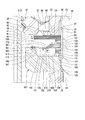
- the piston 18 is a composite of a metal piston body 35 connected to the piston rod 21 and an annular shape that is integrally mounted on the outer peripheral surface of the piston body 35 and slides in the inner cylinder 3. It is composed of a sliding member 36 made of resin.
- the piston body 35 can communicate with a plurality of passage holes 37 capable of communicating the upper chamber 19 and the lower chamber 20 (only one place is shown in FIG. 2 due to the cross section), and the upper chamber 19 and the lower chamber 20 can communicate with each other. There are a plurality of passage holes 39 (only one is shown in FIG. 2 because of the cross section).
- the piston body 35 is a sintered product.
- the plurality of passage holes 37 are formed at equal pitches in the circumferential direction of the piston body 35 with one passage hole 39 sandwiched between them.
- the plurality of passage holes 37 form half of the passage holes 37 and 39.
- the plurality of passage holes 37 have a crank shape having two bending points.
- one side in the axial direction of the piston 18 (upper side in FIG. 2) is outside in the radial direction of the piston 18, and the other side in the axial direction of the piston 18 (lower side in FIG. 2) is a piston rather than one side. It opens inward in the radial direction of 18.
- the piston body 35 is formed with an annular groove 55 on the lower chamber 20 side in the axial direction to communicate a plurality of passage holes 37.
- a first damping force generating mechanism 41 that opens and closes passages in the annular groove 55 and a plurality of passage holes 37 to generate a damping force is provided.
- the passages in the plurality of passage holes 37 and the annular groove 55 move to the upper chamber 19 side of the piston 18, that is, upstream in the extension stroke. It is a passage on the extension side where the oil liquid flows out from the upper chamber 19 on the side to the lower chamber 20 on the downstream side.
- the first damping force generating mechanism 41 provided for the passages in the plurality of passage holes 37 and the annular groove 55 is from the passages in the plurality of passage holes 37 on the extension side and the passages in the annular groove 55 to the lower chamber 20. It is a damping force generation mechanism on the extension side that suppresses the flow of oil and liquid and generates damping force.
- the passage holes 39 which form the other half of the passage holes 37 and 39, are formed at equal pitches with one passage hole 37 sandwiched between them in the circumferential direction of the piston body 35.
- the plurality of passage holes 39 have a crank shape having two bending points.
- the other side in the axial direction of the piston 18 (lower side in FIG. 2) is outside in the radial direction of the piston 18, and the one side in the axial direction of the piston 18 (upper side in FIG. 2) is the piston than the other side. It opens inward in the radial direction of 18.
- the piston body 35 is formed with an annular groove 56 for communicating a plurality of passage holes 39 on the upper chamber 19 side in the axial direction.
- a first damping force generating mechanism 42 for opening and closing the passages in the plurality of passage holes 39 and the annular groove 56 to generate a damping force is provided.
- the passages in the plurality of passage holes 39 and the annular groove 56 move to the lower chamber 20 side of the piston 18, that is, upstream in the contraction stroke. It is a contraction-side passage through which oil liquid flows from the lower chamber 20 on the side to the upper chamber 19 on the downstream side.
- the first damping force generating mechanism 42 provided for the passages in the plurality of passage holes 39 and the annular groove 56 is from the passages in the plurality of passage holes 39 on the contraction side and the passages in the annular groove 56 to the upper chamber 19. It is a damping force generation mechanism on the contraction side that suppresses the flow of oil and liquid and generates damping force.
- the piston body 35 has a substantially disk shape.
- An insertion hole 44 into which the mounting shaft portion 28 of the piston rod 21 is inserted is formed in the center of the piston body 35 in the radial direction so as to penetrate in the axial direction.
- the insertion hole 44 has a small-diameter hole portion 45 on one side in the axial direction for fitting the mounting shaft portion 28 of the piston rod 21, and a large-diameter hole portion 46 on the other side in the axial direction having a larger diameter than the small-diameter hole portion 45. are doing.
- annular inner seat portion 47 is formed inside the piston body 35 in the radial direction from the opening on the lower chamber 20 side of the annular groove 55.
- a part of the first damping force generating mechanism 41 is located outside the opening on the lower chamber 20 side of the annular groove 55 in the radial direction of the piston body 35.
- the annular valve seat portion 48 constituting the above is formed.
- annular inner seat portion 49 is formed inside the piston body 35 in the radial direction from the opening on the upper chamber 19 side of the annular groove 56. ..
- a part of the first damping force generating mechanism 42 is located outside the opening of the annular groove 56 on the upper chamber 19 side in the radial direction of the piston body 35.
- the annular valve seat portion 50 constituting the above is formed.
- the insertion hole 44 of the piston body 35 is provided with a large-diameter hole portion 46 on the inner seat portion 47 side in the axial direction with respect to the small-diameter hole portion 45.
- the passage in the large-diameter hole portion 46 of the piston body 35 is always communicated with the piston rod passage portion 51 in the passage notch 30 of the piston rod 21 so as to overlap the axial position.
- the radial outside of the valve seat portion 48 has a stepped shape having a lower axial height than the valve seat portion 48.
- An opening on the lower chamber 20 side of the passage hole 39 on the contraction side is arranged in this stepped portion.
- the radially outer side of the valve seat portion 50 has a stepped shape having a lower axial height than the valve seat portion 50.
- An opening on the upper chamber 19 side of the passage hole 37 on the extension side is arranged in this stepped portion.
- the first damping force generating mechanism 42 on the contraction side includes the valve seat portion 50 of the piston 18.
- the first damping force generating mechanism 42 on the contraction side includes one disc 62, and a plurality of discs (specifically, four discs) having the same inner diameter and the same outer diameter, in order from the piston 18 side in the axial direction. It has a plurality of (specifically, two) disks 64 having the same inner diameter and the same outer diameter.
- a disk 65, a disk 66, and an annular member 67 are provided in order from the disk 64 side at a position of the disk 64 opposite to the disk 63.
- the annular member 67 is in contact with the shaft step portion 29 of the piston rod 21.
- the discs 62 to 66 and the annular member 67 are made of metal.
- the discs 62 to 66 and the annular member 67 each have a perforated circular flat plate shape having a constant thickness to which the mounting shaft portion 28 of the piston rod 21 can be fitted inside.
- the disc 62 has an outer diameter larger than the outer diameter of the inner seat portion 49 of the piston 18 and a smaller diameter than the inner diameter of the valve seat portion 50.
- the disk 62 is always in contact with the inner sheet portion 49.
- the plurality of discs 63 have an outer diameter substantially equal to the outer diameter of the valve seat portion 50 of the piston 18. The plurality of discs 63 can be seated on the valve seat portion 50.
- the plurality of discs 64 have an outer diameter smaller than the outer diameter of the disc 63.
- the disc 65 has an outer diameter smaller than the outer diameter of the disc 64 and a smaller diameter than the outer diameter of the inner seat portion 49 of the piston 18.
- the disk 66 has an outer diameter larger than the outer diameter of the disk 64 and a smaller diameter than the outer diameter of the disk 63.
- the annular member 67 has an outer diameter smaller than the outer diameter of the disc 66 and a larger diameter than the outer diameter of the shaft step portion 29 of the piston rod 21.
- the annular member 67 is thicker and more rigid than the discs 62 to 66.
- a plurality of discs 63 and a plurality of discs 64 made of a thin metal plate constitute a contraction-side main valve 71 that is flexible and can be taken off and seated on the valve seat portion 50.
- the passages in the annular groove 56 and the plurality of passage holes 39 are communicated with the upper chamber 19, and the flow of oil and liquid between the main valve 71 and the valve seat portion 50.
- the annular member 67 together with the disc 66, regulates the deformation of the main valve 71 in the opening direction beyond the specified value.
- the first passage 72 on the contraction side through which the oil liquid flows out from the lower chamber 20 on the upstream side to the upper chamber 19 on the downstream side is configured. Therefore, the first passage 72 is formed in the piston 18.
- the first damping force generating mechanism 42 on the contraction side that generates damping force includes a main valve 71 and a valve seat portion 50. Therefore, the first damping force generating mechanism 42 on the contraction side is provided in the first passage 72.
- the first passage 72 is provided in the piston 18 including the valve seat portion 50, and the oil liquid passes through when the piston rod 21 and the piston 18 move to the contraction side.
- the first damping force generating mechanism 42 on the contraction side allows both the valve seat portion 50 and the main valve 71 in contact with the valve seat portion 50 to communicate the upper chamber 19 and the lower chamber 20 even when they are in contact with each other. No fixed orifice is formed. That is, the first damping force generating mechanism 42 on the contraction side does not communicate the upper chamber 19 and the lower chamber 20 if the valve seat portion 50 and the main valve 71 are in contact with each other over the entire circumference.
- the first passage 72 is not formed with a fixed orifice that constantly communicates the upper chamber 19 and the lower chamber 20, and is not a passage that constantly communicates the upper chamber 19 and the lower chamber 20.
- the first damping force generating mechanism 41 on the extension side includes the valve seat portion 48 of the piston 18.
- the first damping force generating mechanism 41 on the extension side sequentially comprises one disc 82 and a plurality of (specifically five) discs 83 having the same inner diameter and the same outer diameter from the piston 18 side in the axial direction. Have.
- On the side of the disk 83 opposite to the disk 82 a plurality of (specifically, two) disks 84 having the same inner diameter and the same outer diameter are provided.
- the discs 82 to 84 are made of metal, and all have a perforated circular flat plate shape having a constant thickness to which the mounting shaft portion 28 of the piston rod 21 can be fitted inside.
- the disc 82 has an outer diameter larger than the outer diameter of the inner seat portion 47 of the piston 18 and smaller than the inner diameter of the valve seat portion 48.
- the disk 82 is always in contact with the inner sheet portion 47.
- the disk 82 is formed with a notch portion 88 from an intermediate position outside the inner sheet portion 47 in the radial direction to an inner peripheral edge portion.
- the notch 88 constantly communicates the passage in the annular groove 55 and the plurality of passage holes 37 with the passage in the large-diameter hole 46 of the piston 18 and the piston rod passage 51 in the passage notch 30 of the piston rod 21. Let me.
- the notch 88 is formed during press forming of the disc 82.
- the plurality of discs 83 have an outer diameter substantially equal to the outer diameter of the valve seat portion 48 of the piston 18.
- the plurality of discs 83 can be seated on the valve seat portion 48.
- the disc 84 has an outer diameter smaller than the outer diameter of the disc 83 and smaller than the outer diameter of the inner seat portion 47 of the piston 18.
- a plurality of discs 83 made of a thin metal plate constitute a main valve 91 on the extension side that is flexible and can be taken off and seated on the valve seat portion 48.
- the passages in the annular groove 55 and the plurality of passage holes 37 are communicated with the lower chamber 20, and the flow of oil and liquid between the main valve 91 and the valve seat portion 48. To generate damping force.
- the extension-side first damping force generating mechanism 41 that generates a damping force includes a main valve 91 and a valve seat portion 48. Therefore, the extension-side first damping force generating mechanism 41 is provided in the first passage 92.
- the first passage 92 is provided in the piston 18 including the valve seat portion 48, and the oil liquid passes through when the piston rod 21 and the piston 18 move to the extension side.
- a fixed orifice that communicates the upper chamber 19 and the lower chamber 20 even when they are in contact with each of the valve seat portion 48 and the main valve 91 that abuts on the valve seat portion 48 is provided with a first damping force generating mechanism on the extension side. 41 is not formed. That is, the first damping force generating mechanism 41 on the extension side does not communicate the upper chamber 19 and the lower chamber 20 if the valve seat portion 48 and the main valve 91 are in contact with each other over the entire circumference.
- the first passage 92 is not formed with a fixed orifice that constantly communicates the upper chamber 19 and the lower chamber 20, and is not a passage that constantly communicates the upper chamber 19 and the lower chamber 20.
- the piston rod is composed of 103, one disc 104, one disc valve 105, a plurality of discs 106 (specifically, two discs) having the same inner diameter and the same outer diameter, and one case member 107.
- the mounting shafts 28 of 21 are fitted inside each of them.
- the piston rod 21 is formed with a screw shaft portion 31 on the side opposite to the main shaft portion 27 of the mounting shaft portion 28 and protruding from the case member 107 on the side opposite to the piston 18.
- a nut 108 is screwed into the male screw 32 of the screw shaft portion 31.
- the nut 108 is in contact with the case member 107.
- the screw shaft portion 31 has a male screw 32 which is a complete screw portion screwed into the nut 108, and an incomplete screw portion 109 at the end on the mounting shaft portion 28 side.
- the case member 107 covers the incompletely threaded portion 109.
- the discs 101 to 104, the disc valve 105, the disc 106, and the case member 107 are all made of metal.
- the discs 101 to 104, the disc valve 105, and the disc 106 all have a perforated circular flat plate shape having a constant thickness to which the mounting shaft portion 28 of the piston rod 21 can be fitted inside.
- the case member 107 has an annular shape in which the mounting shaft portion 28 of the piston rod 21 can be fitted.
- the case member 107 is a bottomed tubular integrally molded product.
- the case member 107 includes a perforated disk-shaped bottom portion 111, an annular outer tubular portion 112 (cylindrical portion) projecting from the outer peripheral edge portion of the bottom portion 111 in one axial direction of the bottom portion 111, and an inner portion of the bottom portion 111. It has an annular inner cylinder portion 113 protruding from the peripheral edge portion to the same side as the outer cylinder portion 112.
- the outer tubular portion 112 and the inner tubular portion 113 are arranged coaxially.
- the outer tubular portion 112 has a longer axial length than the inner tubular portion 113.
- the case member 107 is arranged so that the bottom portion 111 is located on the side opposite to the piston 18 with respect to the outer cylinder portion 112 and the inner cylinder portion 113.
- the case member 107 fits into the mounting shaft 28 at the inner peripheral portion of the bottom 111 and covers the incompletely threaded portion 109.
- the outer tubular portion 112 has a continuous annular shape over the entire circumference.
- the inner peripheral surface of the outer tubular portion 112 is a tapered surface whose diameter increases as the distance from the bottom portion 111 in the axial direction increases.
- the outer peripheral surface of the outer tubular portion 112 constitutes the same cylindrical surface as the outer peripheral surface of the bottom portion 111.
- the tip surface of the outer cylinder portion 112 on the side opposite to the bottom portion 111 in the axial direction is a plane orthogonal to the central axis of the case member 107.
- the front end surface of the outer tubular portion 112 and the square edge portion on the boundary side of the inner peripheral surface form an annular shape. It is a first valve seat 115 on which the disc valve 105 is detached and seated. Therefore, the first valve seat 115 is formed in an annular shape on the outer tubular portion 112 of the case member 107.
- the inner tubular portion 113 has a tapered surface whose outer peripheral surface becomes smaller in diameter as the distance from the bottom portion 111 in the axial direction increases.
- the tip surface on the side opposite to the bottom 111 in the axial direction is a plane orthogonal to the central axis of the case member 107.
- a plurality of passage grooves 121 that open in the tip surface and penetrate in the radial direction are formed in the inner tubular portion 113 at intervals in the circumferential direction. Therefore, the inner tubular portion 113 does not have a continuous shape over the entire circumference, but is formed intermittently in the circumferential direction.
- the case member 107 has an insertion hole 125 formed in the center of the case member 107 in the radial direction so as to penetrate the bottom portion 111 and the inner cylinder portion 113 in the axial direction and to insert the mounting shaft portion 28 and the screw shaft portion 31 of the piston rod 21. ing.
- the insertion hole 125 has a small diameter hole portion 126 on one side in the axial direction that fits the mounting shaft portion 28 of the piston rod 21 and covers the incomplete screw portion 109 of the screw shaft portion 31, and a diameter larger than that of the small diameter hole portion 126. It has a large-diameter hole portion 127 on the other side in the axial direction.
- the large-diameter hole portion 127 is formed so as to penetrate the inner cylinder portion 113 to the inner cylinder portion 113 in the axial direction of the bottom portion 111, and the small-diameter hole portion 126 is different from the inner cylinder portion 113 in the axial direction of the bottom portion 111. It is formed on the opposite side. Therefore, a plurality of passage grooves 121 are all open on the inner peripheral surface of the large-diameter hole portion 127.
- the passage in the large-diameter hole portion 127 is always communicated with the piston rod passage portion 51 in the passage notch 30 of the piston rod 21 so as to overlap the axial position.
- the chamber passage portion 131 in the passage groove 121 of the inner cylinder portion 113 is always in communication with the passage in the large diameter hole portion 127.
- the incomplete threaded portion 109 is arranged within the axial range of the bottom portion 111 of the case member 107.
- the mounting shafts 28 and the male screw 32 on both sides of the bottom 111 of the case member 107 in the axial direction are arranged.
- the case member 107 is positioned in the radial direction with the bottom portion 111 fitted to the mounting shaft portion 28 in the small diameter hole portion 126.
- the disc 101 has an outer diameter larger than the outer diameter of the disc 84, and is thicker than the disc 84.
- the disc 102 has an outer diameter larger than the outer diameter of the disc 101, and is thinner than the disc 101.
- the disk 103 has an outer diameter larger than the outer diameter of the disk 102, and is thinner than the disk 101 and thicker than the disk 102.
- the disk 104 has an outer diameter larger than the outer diameter of the disk 103, and is thinner than the disk 103. Therefore, the outer diameters of the discs 101 to 104 become larger as they are closer to the bottom 111 of the case member 107 in the axial direction.
- the outer diameter of the disc 104 is smaller than the inner diameter of the tip surface of the outer cylinder portion 112 of the case member 107, in other words, the inner diameter of the first valve seat 115.
- the end surface of the disk 104 on the bottom 111 side is closer to the bottom 111 side in the axial direction than the tip surface of the outer tubular portion 112 of the case member 107, in other words, the end surface of the first valve seat 115 on the side opposite to the bottom 111. Have been placed.
- the disc valve 105 is detached and seated on the outer peripheral portion of the annular shape on the case member 107 side in the axial direction of the disc 104.
- the disc 104 together with the discs 101 to 103 laminated thereto, constitutes a second valve seat 135 on which the disc valve 105 is detached and seated.
- the second valve seat 135 supports the disc valve 105 when seated.
- the second valve seat 135 composed of the discs 101 to 104 has the piston rod 21 inserted inward in the radial direction.
- the second valve seat 135 is arranged radially inward with respect to the first valve seat 115 of the case member 107, and is located on the bottom 111 side in the axial direction.
- the outer diameter of the discs 101 to 104 becomes smaller as the distance from the case member 107 in the axial direction increases. Since the discs 101 to 104 are made of a thin metal plate, the second valve seat 135 made of the discs 101 to 104 has a flexible structure.
- the first valve seat 115 of the case member 107 has higher rigidity than the second valve seat 135 and basically does not bend.
- the support rigidity of the disc valve 105 can be adjusted by changing the thickness and outer diameter of each of the discs 101 to 104, the number of the second valve seat 135, and the like.
- the disk 106 has an outer diameter smaller than the outer diameter of the disk 104.
- the disk 106 has an outer diameter equivalent to the outer diameter of the disk 84.
- the outer diameter of the disk 106 is the same as the outer diameter of the tip surface of the inner cylinder portion 113 of the case member 107 on the side opposite to the bottom portion 111.
- the disc valve 105 is made of a thin metal plate and is flexible.
- the disc valve 105 has a flat plate shape as a whole in a natural state before being incorporated into the shock absorber 1.
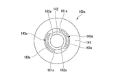
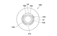
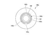
- the disc valve 105 in the natural state has a perforated circular flat plate-shaped outer annular portion 141 and an outer diameter smaller than the inner diameter of the outer annular portion 141, and has a diameter of the outer annular portion 141.
- It has a perforated circular flat plate-shaped inner annular portion 142 arranged inside in the direction, and a plurality of, specifically, two support portions 143 connecting the outer annular portion 141 and the inner annular portion 142.
- the disc valve 105 has a mirror-symmetrical shape.
- the outer peripheral surface and the inner peripheral surface of the outer annular portion 141 are both circular and concentrically arranged, in other words, the outer annular portion 141 has an annular shape having a constant radial width.
- the outer peripheral surface and the inner peripheral surface of the inner annular portion 142 are both circular and concentrically arranged, in other words, they form an annular shape having a constant radial width.
- the two support portions 143 are arranged between the inner annular portion 142 and the outer annular portion 141. The two support portions 143 concentrically support the outer annular portion 141 on the inner annular portion 142.
- the inner annular portion 142 is inserted with the mounting shaft portion 28 of the piston rod 21 inside.
- the inner diameter of the inner annular portion 142 is such that the mounting shaft portion 28 of the piston rod 21 can be fitted, and the outer diameter is smaller than the outer diameter of the disc 104, that is, the outer diameter of the second valve seat 135.
- the outer diameter of the inner annular portion 142 is equal to the outer diameter of the tip surface of the inner tubular portion 113 of the case member 107 and the outer diameter of the disc 106. Therefore, in the disc valve 105, the inner annular portion 142 is clamped in the axial direction by the disc 84 and the disc 106 together with the discs 101 to 104.
- the inner diameter of the outer annular portion 141 is smaller than the outer diameter of the disc 104, that is, the outer diameter of the second valve seat 135.
- the outer diameter of the outer annular portion 141 is larger than the inner diameter of the tip surface of the outer tubular portion 112 of the case member 107, that is, the diameter of the first valve seat 115.
- the outer diameter of the outer annular portion 141, that is, the outer diameter of the disc valve 105 is larger than the outer diameter of the main valve 91.
- the outer annular portion 141 is capable of detaching the outer peripheral side disengagement portion 151 (disengagement portion) on the outer peripheral side from the first valve seat 115 of the case member 107.
- the outer annular portion 141 closes the gap with the first valve seat 115 when the outer peripheral side disconnection portion 151 sits on the first valve seat 115 over the entire circumference.
- the outer annular portion 141 opens a gap with the first valve seat 115.
- the outer annular portion 141 is capable of detaching the inner peripheral side separating portion 152 on the inner peripheral side from the second valve seat 135 of the disc 104.
- the outer annular portion 141 closes the gap with the second valve seat 135 when the inner peripheral side disconnection portion 152 sits on the second valve seat 135 over the entire circumference.
- the outer annular portion 141 opens a gap with the second valve seat 135.
- the disc 104 closes the gap between the outer annular portion 141 and the inner annular portion 142 of the disc valve 105.
- the outer peripheral side detaching portion 151 on the outer peripheral side is arranged so as to be detachable from the first valve seat 115 of the case member 107.
- the second valve seat 135 is provided on the side opposite to the first valve seat 115 in the axial direction of the disc valve 105, and the inner peripheral side disconnection portion 152 radially inside the outer peripheral side disconnection portion 151 of the disc valve 105. Is supported so that it can be detached.
- the two support portions 143 have two outer connecting portions 161, two inner connecting portions 162, and two connecting arm portions 163.
- the two outer connecting portions 161 are arranged on the same side of the center in the radial direction of the disc valve 105 at intervals in the circumferential direction of the disc valve 105, and are connected to the outer annular portion 141. .. Both of the two outer connecting portions 161 project radially inward from the inner peripheral edge portion of the outer annular portion 141 to the outer annular portion 141.
- the two inner connecting portions 162 are spaced apart from the center in the radial direction of the disc valve 105, that is, on the opposite side of the two outer connecting portions 161 in the circumferential direction of the disc valve 105. Is arranged and connected to the inner annular portion 142. Each of the two inner connecting portions 162 protrudes outward in the radial direction from the outer peripheral edge portion of the inner annular portion 142.
- the distance between the two inner connection parts 162 is wider than the distance between the two outer connection parts 161.
- the straight line connecting the two inner connecting portions 162 and the straight line connecting the two outer connecting portions 161 are parallel to each other. Therefore, the straight line connecting the midpoint of the straight line connecting the two inner connecting portions 162 and the midpoint of the straight line connecting the two outer connecting portions 161 is the center of the inner annular portion 142 and the outer annular portion 141. That is, it passes through the center of the disc valve 105.
- the distance between the outer connecting portion 161 and the inner connecting portion 162 which are close in the circumferential direction of the disc valve 105 is equal to the distance between the outer connecting portion 161 and the inner connecting portion 162 which are close in the circumferential direction of the disc valve 105. ing. This distance is longer than the distance connecting the two inner connecting portions 162 and longer than the distance connecting the two outer connecting portions 161.
- the two connecting arm portions 163 are provided so as to connect the outer connecting portion 161 and the inner connecting portion 162, which are close to the circumferential direction of the disc valve 105, respectively. That is, one connecting arm portion 163 connects one outer connecting portion 161 and one inner connecting portion 162 that are close to each other in the circumferential direction of the disc valve 105.
- the outer connection portion 161 and the inner connection portion 162 constitute one support portion 143.
- the other connecting arm portion 163 connects the other outer connecting portion 161 and the other inner connecting portion 162, which are close to each other in the circumferential direction of the disc valve 105.
- the outer connection portion 161 and the inner connection portion 162 form the other support portion 143.
- the two connecting arm portions 163 extend in an arc shape along the inner peripheral surface of the outer annular portion 141 and the outer peripheral surface of the inner annular portion 142, and are concentric with the outer annular portion 141 and the inner annular portion 142. It is placed on top. In the two connecting arm portions 163, the radial distance from the inner peripheral surface of the outer annular portion 141 and the radial distance from the outer peripheral surface of the inner annular portion 142 are equal.
- the disc 104 constituting the second valve seat 135 becomes It shuts off between the outer annular portion 141 and the inner annular portion 142 of the disc valve 105.
- the second valve seat 135 is provided so as to be able to cut off between the outer annular portion 141 and the inner annular portion 142 of the disc valve 105.
- the disc valve 105, the plurality of discs 106, and the case member 107 form a case inner chamber 165 inside them.
- a predetermined range on the side opposite to the outer tubular portion 112 and the inner tubular portion 113 in the axial direction of the bottom portion 111 covers the incompletely threaded portion 109 of the piston rod 21.
- this range is the washer portion 166.
- the case member 107, the outer cylinder portion 112, the inner cylinder portion 113, and the predetermined range on the outer cylinder portion 112 and the inner cylinder portion 113 side in the axial direction of the bottom portion 111 form the chamber passage portion 131 and the case inner chamber 165.
- the case member 107 is integrally molded including the case portion 167 forming the chamber passage portion 131 and the case inner chamber 165, and the washer portion 166 covering the incompletely threaded portion 109 of the piston rod 21.
- the incomplete threaded portion 109 is arranged within the axial range of the washer portion 166.
- the mounting shaft portions 28 and the male screw 32 on both sides of the washer portion 166 in the axial direction are arranged.
- the case member 107 is positioned in the radial direction with the washer portion 166 fitted to the mounting shaft portion 28.
- the disc 106 or the like can be properly fitted by completely superimposing the mounting shaft portion 28 and the axial position.
- the nut 108 can be properly screwed by completely superimposing the axial position on the male screw 32 which is a completely threaded portion.
- the washer portion 166 also serves to stabilize and balance the fastening axial force of the nut 108.
- the case inner chamber 165 is constantly communicated with the passage in the large-diameter hole portion 127 and the piston rod passage portion 51 in the passage notch 30 via the chamber passage portion 131 in the passage groove 121 of the inner cylinder portion 113. ..
- the chamber passage portion 131 communicates from the piston rod passage portion 51 to the case inner chamber 165 between the bottom portion 111 and the disc valve 105. Therefore, the case inner chamber 165 includes a chamber passage portion 131 in the passage groove 121, a passage in the large-diameter hole portion 127 of the case member 107, and a piston rod passage portion 51 in the passage cutout portion 30 of the piston rod 21. As shown in FIG.
- the inner peripheral side of the outer annular portion 141 of the disc valve 105 including the inner peripheral side detaching portion 152 constitutes a sub-valve 171 that can be detached and seated on the second valve seat 135.
- the sub valve 171 is provided on the lower chamber 20 side of the upper chamber 19 and the lower chamber 20.
- the sub valve 171 is provided on the case inner chamber 165 side of the lower chamber 20 and the case inner chamber 165.
- the sub valve 171 By separating the sub valve 171 from the second valve seat 135, the lower chamber 20 passes through the gap between the second valve seat 135 and the passage between the outer annular portion 141 and the inner annular portion 142 of the disc valve 105. And the case inner chamber 165 are communicated with each other. Therefore, the sub valve 171 communicates the lower chamber 20 with the upper chamber 19. At this time, the sub-valve 171 suppresses the flow of the oil liquid with the second valve seat 135 to generate a damping force.
- the sub-valve 171 is an inflow valve that opens when oil liquid flows from the lower chamber 20 into the case inner chamber 165 through a gap with the second valve seat 135.
- the sub-valve 171 is a check valve that regulates the outflow of oil liquid from the case inner chamber 165 to the lower chamber 20 through a gap with the second valve seat 135.
- the passage in the notch 88 and the passage in the annular groove 55 and in the plurality of passage holes 37 are on the downstream side from the lower chamber 20 which becomes the upstream side in the cylinder 2 due to the movement of the piston 18 to the lower chamber 20 side.
- a second passage 172 through which the oil liquid flows out to the upper chamber 19 is configured.
- the second passage 172 is a passage on the contraction side in which the oil liquid flows from the lower chamber 20 on the upstream side to the upper chamber 19 on the downstream side in the movement of the piston 18 to the lower chamber 20 side, that is, in the contraction stroke.
- the second passage 172 includes the piston rod passage portion 51 in the passage notch 30 formed by cutting out the piston rod 21.
- a part of the second passage 172 is formed by cutting out the piston rod 21.
- one end opens in the passage in the large-diameter hole portion 127 of the case member 107, and the other end opens in the passage in the large-diameter hole portion 46 of the piston 18.
- the piston rod passage portion 51 may be formed by penetrating the inside of the piston rod 21 in a hole shape.
- the second passage 172 is a case between the piston rod passage portion 51 formed by notching or penetrating the piston rod 21 and the bottom portion 111 of the case member 107 from the piston rod passage portion 51 and the disc valve 105. It has a chamber passage portion 131 that communicates with the inner chamber 165.
- the sub valve 171 and the second valve seat 135 are provided in the second aisle 172 on the contraction side.
- the second passage 172 is opened and closed to form a contraction-side second damping force generation mechanism 173 that suppresses the flow of oil liquid from the second passage 172 to the upper chamber 19 to generate a damping force.
- the sub-valve 171 constituting the second damping force generating mechanism 173 on the contraction side is a sub-valve on the contraction side.
- the second damping force generating mechanism 173 including the sub valve 171 and the second valve seat 135 inserts the piston rod 21 inward in the radial direction.
- the second damping force generation mechanism 173 is arranged on the lower chamber 20 side of one of the two upper chambers 19 and the lower chamber 20.
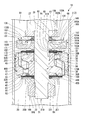
- the passage in the notch 88 of the disk 82 shown in FIG. 3 becomes the narrowest in the portion where the cross section of the flow path is fixed. It is squeezed more than before and after. As a result, the passage in the notch 88 of the disk 82 becomes the orifice 175 in the second passage 172.
- the orifice 175 is arranged on the downstream side of the sub valve 171 for the flow of the oil liquid when the sub valve 171 is opened and the oil liquid flows in the second passage 172. In other words, as shown in FIG. 2, the orifice 175 is arranged on the upper chamber 19 side of the sub valve 171 in the second passage 172.
- the second damping force generating mechanism 173 on the contraction side is fixed to both the second valve seat 135 and the sub-valve 171 in contact with the second valve seat 135 so as to communicate the upper chamber 19 and the lower chamber 20 even when they are in contact with each other. No orifice is formed. That is, the second damping force generating mechanism 173 on the contraction side does not communicate the upper chamber 19 and the lower chamber 20 as long as the second valve seat 135 and the sub valve 171 are in contact with each other over the entire circumference.
- the second passage 172 is not formed with a fixed orifice that constantly communicates the upper chamber 19 and the lower chamber 20, and is not a passage that constantly communicates the upper chamber 19 and the lower chamber 20.
- the contraction-side second passage 172 that can communicate the upper chamber 19 and the lower chamber 20 is parallel to the first passage 72 that is the contraction-side passage that can also communicate the upper chamber 19 and the lower chamber 20.
- a first damping force generating mechanism 42 is provided in the first passage 72, and a second damping force generating mechanism 173 is provided in the second passage 172. Therefore, the first damping force generating mechanism 42 and the second damping force generating mechanism 173 on the contraction side are arranged in parallel.
- the outer peripheral side including the outer peripheral side detaching portion 151 of the outer annular portion 141 of the disc valve 105 constitutes a sub valve 181 that can be detached and seated on the first valve seat 115.
- the sub valve 181 is provided on the lower chamber 20 side of the upper chamber 19 and the lower chamber 20.
- the sub valve 181 is provided on the lower chamber 20 side of the lower chamber 20 and the case inner chamber 165.
- the upper chamber 19 becomes the lower chamber 20 by communicating the case inner chamber 165 and the lower chamber 20 through a gap with the first valve seat 115. Communicate.
- the sub valve 181 suppresses the flow of the oil liquid between the sub valve 181 and the first valve seat 115 to generate a damping force.
- the sub valve 181 is a discharge valve that opens when the oil liquid is discharged from the case inner chamber 165 to the lower chamber 20 through the gap with the first valve seat 115.
- the sub-valve 181 is a check valve that regulates the inflow of oil liquid from the lower chamber 20 into the case inner chamber 165 through a gap with the first valve seat 115.
- the passage between the seats 115 constitutes a second passage 182 in which the oil liquid flows out from the upper chamber 19 on the upstream side in the cylinder 2 to the lower chamber 20 on the downstream side by moving the piston 18 to the upper chamber 19 side. are doing.
- the second passage 182 is a passage on the extension side in which the oil liquid flows out from the upper chamber 19 on the upstream side to the lower chamber 20 on the downstream side in the movement of the piston 18 to the upper chamber 19 side, that is, in the extension
- the second passage 182 includes the piston rod passage portion 51 in the passage notch 30 formed by cutting the piston rod 21. In other words, a part thereof is formed by cutting out the piston rod 21.
- the piston rod passage portion 51 may be formed by penetrating the inside of the piston rod 21 in a hole shape. Therefore, the second passage 182 is a case between the piston rod passage portion 51 formed by notching or penetrating the piston rod 21 and the bottom portion 111 of the case member 107 from the piston rod passage portion 51 and the disc valve 105. It has a chamber passage portion 131 that communicates with the inner chamber 165.
- the sub valve 181 and the annular first valve seat 115 formed on the outer tubular portion 112 of the case member 107 are provided in the second passage 182 on the extension side.
- the second passage 182 is opened and closed, and a second damping force generation mechanism 183 on the extension side that suppresses the flow of oil liquid from the second passage 182 to the lower chamber 20 to generate a damping force is configured.
- the first valve seat 115 is provided on the case member 107.
- the sub-valve 181 constituting the extension-side second damping force generation mechanism 183 is an extension-side sub-valve.
- the second damping force generating mechanism 183 composed of the sub valve 181 and the first valve seat 115 has the piston rod 21 inserted radially inward, and the lower chamber 20 of the two upper chambers 19 and the lower chamber 20 is inserted. It is located on the side.
- the passage in the notch 88 of the disk 82 shown in FIG. 3 becomes the narrowest in the portion where the cross section of the flow path is fixed. It is squeezed more than before and after.
- the passage in the notch 88 of the disk 82 also serves as an orifice 175 in the second passage 182.
- the orifice 175 is common to the second passages 172 and 182.
- the orifice 175 is arranged on the upstream side of the sub valve 181 of the flow of the oil liquid when the sub valve 181 is opened and the oil liquid flows in the second passage 182. In other words, as shown in FIG.
- the orifice 175 is arranged on the upper chamber 19 side of the sub valve 181 in the second passage 182.
- the orifice 175 is formed by cutting out a disc 82 that abuts on the piston 18 among the parts constituting the first damping force generating mechanism 41.
- the second damping force generating mechanism 183 on the extension side is fixed to both the first valve seat 115 and the sub-valve 181 in contact with the first valve seat 115 so as to communicate the upper chamber 19 and the lower chamber 20 even when they are in contact with each other. No orifice is formed. That is, the second damping force generating mechanism 183 on the extension side does not communicate the upper chamber 19 and the lower chamber 20 as long as the first valve seat 115 and the sub valve 181 are in contact with each other over the entire circumference.
- the second passage 182 is not formed with a fixed orifice that constantly communicates the upper chamber 19 and the lower chamber 20.
- the second passage 182 is not a passage that always connects the upper chamber 19 and the lower chamber 20.
- the shock absorber 1 In the shock absorber 1, the upper chamber 19 and the lower chamber 20 have the first damping force generating mechanisms 41 and 42 and the second damping force generating mechanism 1733 as the flow for passing the oil liquid in the axial direction at least in the piston 18. Communication is possible only via 183. Therefore, the shock absorber 1 is not provided with a fixed orifice that constantly communicates the upper chamber 19 and the lower chamber 20 at least on the passage of the oil liquid that passes through the piston 18 in the axial direction.
- the extension-side second passage 182 that can communicate the upper chamber 19 and the lower chamber 20 is the extension-side passage 92 that can also communicate the upper chamber 19 and the lower chamber 20, and the upper chamber 19 side. Except for the passages in the plurality of passage holes 37 and the annular groove 55, they are arranged in parallel. In the parallel portion, a first damping force generating mechanism 41 is provided in the first passage 92, and a second damping force generating mechanism 183 is provided in the second passage 182. Therefore, the first damping force generating mechanism 41 and the second damping force generating mechanism 183 on the extension side are arranged in parallel.
- the second damping force generating mechanism 173, 183 is the first annular shape formed on the outer cylinder portion 112 of the bottomed tubular case member 107 having the bottom portion 111, the outer cylinder portion 112, and the inner cylinder portion 113.
- the second damping force generation mechanism 173 is provided at the end position of the second passage 172.
- the second damping force generation mechanism 183 is provided at the end position of the second passage 182.
- the base valve 25 is provided between the bottom member 12 of the outer cylinder 4 and the inner cylinder 3.
- the base valve 25 includes a base valve member 191 that separates the lower chamber 20 and the reservoir chamber 6, a disk 192 provided on the lower side of the base valve member 191, that is, on the reservoir chamber 6 side, and an upper side, that is, a lower side of the base valve member 191. It has a disc 193 provided on the chamber 20 side, and a mounting pin 194 for mounting the disc 192 and the disc 193 to the base valve member 191.
- the base valve member 191 has an annular shape, and the mounting pin 194 is inserted in the center in the radial direction.
- the base valve member 191 has a plurality of passage holes 195 through which oil and liquid can flow between the lower chamber 20 and the reservoir chamber 6, and is below the passage holes 195 outside the base valve member 191 in the radial direction.
- a plurality of passage holes 196 capable of flowing oil liquid are formed between the chamber 20 and the reservoir chamber 6.
- the disk 192 on the reservoir chamber 6 side allows the flow of oil liquid from the lower chamber 20 to the reservoir chamber 6 through the passage hole 195, while allowing the oil liquid to flow from the reservoir chamber 6 to the lower chamber 20 through the passage hole 195. Suppress the flow.
- the disk 193 allows the flow of oil liquid from the reservoir chamber 6 to the lower chamber 20 through the passage hole 196, while suppressing the flow of oil liquid from the lower chamber 20 through the passage hole 196 to the reservoir chamber 6.
- the disk 192 and the base valve member 191 form a compression valve mechanism 197 on the contraction side that opens the valve in the contraction stroke of the shock absorber 1 to allow oil and liquid to flow from the lower chamber 20 to the reservoir chamber 6 and generate a damping force.
- the disk 193, together with the base valve member 191, constitutes a suction valve mechanism 198 that opens a valve in the extension stroke of the shock absorber 1 and allows oil liquid to flow from the reservoir chamber 6 into the lower chamber 20.
- the suction valve mechanism 198 applies oil and liquid from the reservoir chamber 6 to the lower chamber 20 without substantially generating a damping force so as to make up for the shortage of the liquid mainly caused by the extension of the piston rod 21 from the cylinder 2. It fulfills the function of flowing.
- the annular member 67 and the disc 66 are inserted into the shaft step portion 29 while inserting the screw shaft portion 31 and the mounting shaft portion 28 of the piston rod 21.
- Disc 65, a plurality of discs 64, a plurality of discs 63, a disc 62, and a piston 18 are stacked in this order.
- the piston 18 is oriented so that the small-diameter hole portion 45 is located closer to the shaft step portion 29 than the large-diameter hole portion 46.
- the disc 82, the plurality of discs 83, the plurality of discs 84, the disc 101, the disc 102, and the disc 103 are inserted into the piston 18.
- the disc 104, the disc valve 105, the plurality of discs 106, and the case member 107 are stacked in this order.
- the case member 107 is oriented so that the outer cylinder portion 112 and the inner cylinder portion 113 are located closer to the piston 18 than the bottom portion 111.
- the case member 107 abuts on the disc 106 on the inner cylinder 113 and on the outer annular portion 141 of the disc valve 105 on the outer cylinder 112.
- the nut 108 is screwed into the male screw 32 of the screw shaft portion 31 of the piston rod 21 protruding from the case member 107, and the nut 108 and the shaft step portion 29 are axially oriented on the inner peripheral side thereof. Clamp.
- the discs 101 to 104 constituting the second valve seat 135 and the disc valve 105 are clamped to the disc 84 and the disc 106 on the inner peripheral side.
- the disc valve 105 is clamped at the inner annular portion 142.
- the support portion 143 and the outer annular portion 141 shown in FIG. 4 are not clamped.
- the sub-valve 171 of the outer annular portion 141 of the disc valve 105 abuts on the second valve seat 135 at the inner peripheral side disconnection portion 152 from the side opposite to the piston 18 over the entire circumference.
- the sub-valve 181 of the outer annular portion 141 abuts on the first valve seat 115 at the outer peripheral side disconnection portion 151 from the piston 18 side over the entire circumference.
- the second valve seat 135 is located on the bottom 111 side in the axial direction of the first valve seat 115, that is, on the side opposite to the piston 18. Therefore, the outer annular portion 141 that abuts on the first valve seat 115 and the second valve seat 135 at the same time is deformed in a tapered shape so as to be separated from the piston 18 in the axial direction toward the inner side in the radial direction.
- the outer peripheral side contacting portion 151 on the first valve seat 115 side is located on the piston 18 side in the axial direction with respect to the inner peripheral side separating portion 152 on the second valve seat 135 side. It deforms into a taper shape.
- the main valve 91 of the first damping force generating mechanism 41 is configured by stacking a plurality of disks 83. Therefore, the rigidity is higher and the valve opening pressure is higher than that of the sub valve 181 of the second damping force generating mechanism 183 composed of one disc valve 105. Therefore, in the extension stroke, the second damping force generating mechanism 183 opens with the first damping force generating mechanism 41 closed in the extremely low speed region where the piston speed is lower than the predetermined value. In the normal speed region where the piston speed is equal to or higher than this predetermined value, both the first damping force generating mechanism 41 and the second damping force generating mechanism 183 open.
- the sub-valve 181 is an extremely low-speed valve that opens in a region where the piston speed is extremely low and generates a damping force.
- the sub valve 181 is separated from the first valve seat 115, and the upper chamber 19 and the lower chamber 20 are communicated with each other through the second passage 182 on the extension side. Therefore, the oil liquid in the upper chamber 19 flows through the passages in the plurality of passage holes 37 and the annular groove 55 of the piston 18, the orifice 175, the passage in the large diameter hole portion 46 of the piston 18, and the passage of the piston rod 21.
- the first damping force generating mechanism 41 opens while the second damping force generating mechanism 183 remains open. That is, the sub valve 181 is separated from the first valve seat 115, and the oil liquid flows from the upper chamber 19 to the lower chamber 20 in the second passage 182 on the extension side. At this time, the flow of the oil liquid is throttled by the orifice 175 provided on the downstream side of the main valve 91 in the second passage 182, so that the pressure applied to the main valve 91 increases and the differential pressure increases.
- the main valve 91 is separated from the valve seat portion 48, and the oil liquid flows from the upper chamber 19 to the lower chamber 20 in the first passage 92 on the extension side. Therefore, the oil liquid in the upper chamber 19 flows into the lower chamber 20 via the passages in the plurality of passage holes 37 and the annular groove 55 and the passages between the main valve 91 and the valve seat portion 48.
- the differential pressure between the upper chamber 19 and the lower chamber 20 is larger than the low speed region where the first predetermined value v1 or more and less than the second predetermined value v2.
- the first passage 92 does not have a throttle due to an orifice, the oil liquid can flow through the first passage 92 at a large flow rate by opening the main valve 91.
- a flow path for flowing oil liquid from the upper chamber 19 to the lower chamber 20 is provided in parallel with the first passage 92 and the second passage 182 in the extension stroke, and the main valve 91 and the sub valve 181 are provided in parallel. There is.
- the orifice 175 is connected in series with the sub valve 181.
- the main valve 91 is opened so that the oil liquid can flow at a large flow rate through the first passage 92. ..
- the flow rate flowing through the passage between the sub valve 181 and the first valve seat 115 is reduced. Therefore, the valve rigidity of the sub valve 181 can be reduced. Therefore, for example, it is possible to reduce the rate of increase in the damping force with respect to the increase in the piston speed in the normal speed region (v2 or more).
- the slope of the rate of increase in the damping force on the extension side with respect to the increase in piston speed in the normal speed region (v2 or more) can be laid down more than in the extremely low speed region (less than v2).
- the degree of freedom in design can be expanded.
- the main valve 71 of the first damping force generating mechanism 42 is configured by stacking a plurality of disks 63 and 64. Therefore, the rigidity is higher and the valve opening pressure is higher than the sub valve 171 of the second damping force generating mechanism 173 composed of one disc valve 105. Therefore, in the contraction stroke, in the extremely low speed region where the piston speed is lower than the predetermined value, the second damping force generating mechanism 173 opens with the first damping force generating mechanism 42 closed, and the piston speed is the predetermined value. In the above normal speed region, both the first damping force generating mechanism 42 and the second damping force generating mechanism 173 open.
- the sub valve 171 is an extremely low speed valve that opens in a region where the piston speed is extremely low and generates a damping force.
- the pressure of the lower chamber 20 increases and the pressure of the upper chamber 19 decreases as the piston 18 moves to the lower chamber 20 side. Since neither the first damping force generating mechanism 41, 42 nor the second damping force generating mechanism 173, 183 has a fixed orifice, the oil liquid does not flow until the second damping force generating mechanism 173 is opened. Therefore, the damping force rises sharply. In the region where the piston speed is higher than the third predetermined value at which the second damping force generating mechanism 173 opens, and in the extremely low speed region where the piston speed is faster than the third predetermined value and lower than the fourth predetermined value, the second The second damping force generating mechanism 173 opens with the first damping force generating mechanism 42 closed.
- the sub valve 171 is separated from the second valve seat 135, and the lower chamber 20 and the upper chamber 19 are communicated with each other in the second passage 172 on the contraction side. Therefore, the oil liquid in the lower chamber 20 is the passage between the sub valve 171 and the second valve seat 135, the passage between the outer annular portion 141 and the inner annular portion 142 of the disc valve 105, the case inner chamber 165, and the case.
- the damping force of the valve characteristic (the characteristic in which the damping force is substantially proportional to the piston speed) can be obtained even in the extremely low speed region where the piston speed is lower than the fourth predetermined value.
- the first damping force generating mechanism 42 opens while the second damping force generating mechanism 173 remains open. That is, the sub valve 171 is separated from the second valve seat 135, and the oil liquid flows from the lower chamber 20 to the upper chamber 19 in the second passage 172 on the contraction side. At this time, since the flow rate of the oil liquid is throttled by the orifice 175 in the second passage 172, the differential pressure generated in the main valve 71 becomes large. The main valve 71 is separated from the valve seat portion 50, and the oil liquid flows from the lower chamber 20 to the upper chamber 19 in the first passage 72 on the contraction side.
- the oil liquid in the lower chamber 20 flows through the passages in the plurality of passage holes 39 and the annular groove 56, and the passages between the main valve 71 and the valve seat portion 50.
- the damping force having valve characteristics (damping force is substantially proportional to the piston speed) can be obtained.
- the rate of increase in the damping force on the contraction side with respect to the increase in piston speed in the normal speed region is lower than the rate of increase in the damping force on the contraction side with respect to the increase in piston speed in the extremely low speed region.
- the slope of the rate of increase in the damping force on the contraction side with respect to the increase in piston speed in the normal speed region can be laid down more than in the extremely low speed region.
- the differential pressure between the lower chamber 20 and the upper chamber 19 becomes larger than in the low speed region. Since the first passage 72 is not throttled by the orifice, the oil liquid can flow at a large flow rate through the first passage 72 by opening the main valve 71. As a result, the flow rate flowing through the sub valve 171 is reduced, so that the valve rigidity of the sub valve 171 can be reduced. Therefore, the damping force in the normal speed region of the piston speed can be reduced, and the degree of freedom in design can be expanded.
- the differential pressure generated on the upstream side and downstream side surfaces of the sub valve 181 is small, and it is possible to suppress the application of a large back pressure from the lower chamber 20 side toward the case inner chamber 165 side to the sub valve 181 side of the outer annular portion 141. ..
- a flow path for flowing oil liquid from the lower chamber 20 to the upper chamber 19 is provided in parallel with the first passage 72 and the second passage 172 in the contraction stroke, and the main valve 71 and the sub valve 171 are arranged in parallel. It is provided.
- the orifice 175 is connected in series with the sub valve 171 in the second passage 172.
- the differential pressure between the upper chamber 19 and the lower chamber 20 becomes large in the normal speed region where the piston speed is equal to or higher than the second predetermined value.
- the sub valve 181 When the sub valve 181 is opened, the lower chamber 20 and the case inner chamber 165 are communicated with each other, and the orifice 175 formed on the upstream side of the sub valve 171 can suppress the pressure increase in the case inner chamber 165. Therefore, deformation of the outer annular portion 141 due to back pressure on the sub valve 171 side can be suppressed.
- the differential pressure between the lower chamber 20 and the upper chamber 19 becomes larger in the normal speed region where the piston speed is equal to or higher than the fourth predetermined value than in the low speed region.
- Deformation of the sub-valve 171 can be suppressed by flowing the oil liquid at a large flow rate in the first passage 72 and by narrowing the downstream side of the second passage 172 from the sub-valve 171 with the orifice 175. Therefore, the durability of the sub valve 171 can be improved.
- the differential pressure between the upper chamber 19 and the lower chamber 20 becomes larger in the normal speed region where the piston speed is equal to or higher than the second predetermined value than in the low speed region.
- Deformation of the outer annular portion 141 on the sub valve 181 side can be suppressed by flowing the oil liquid at a large flow rate in the first passage 92 and narrowing the second passage 182 by the orifice 175.
- the differential pressure between the lower chamber 20 and the upper chamber 19 becomes large in the normal speed region where the piston speed is equal to or higher than the fourth predetermined value.
- the lower chamber 20 and the case inner chamber 165 are communicated with each other, and the case inner chamber 165 is an orifice 175 provided between the upper chamber 19 and the flow of oil liquid to the upper chamber 19. Is squeezed. Therefore, the differential pressure between the lower chamber 20 and the case inner chamber 165 is small, and deformation of the outer annular portion 141 on the sub valve 181 side due to back pressure can be suppressed. Therefore, the durability of the sub valve 181 can be improved.
- Patent Documents 1 to 3 describe a shock absorber having two valves that open in the same process. Having two valves that open in the same stroke causes problems such as a complicated structure, an increase in the number of parts, and an increase in the axial length. In such a shock absorber, simplification of the structure is required.
- the shock absorber 1 of the first embodiment has two first damping force generating mechanisms 41 and a second damping force generating mechanism 183 that open the valve in the extension stroke.
- the shock absorber 1 of the first embodiment has two first damping force generating mechanisms 42 and a second damping force generating mechanism 173 that open the valve in the contraction stroke.
- the second damping force generating mechanism 173, 183 is an annular number formed on the outer tubular portion 112 of the bottomed tubular case member 107 having the bottom portion 111 and the outer tubular portion 112.
- the structure can be simplified, the number of parts can be reduced, and the length in the axial direction can be suppressed.
- the disc valve 105 constituting the second damping force generating mechanism 173, 183 has an outer annular portion 141 arranged so as to be detachable from the first valve seat 115 and the second valve seat 135, and an inner annular portion through which the piston rod 21 is inserted. It has a portion 142 and a support portion 143 connecting them. Therefore, while the inner annular portion 142 and the support portion 143 suppress the positional deviation of the outer annular portion 141 that opens and closes in contact with the first valve seat 115 and the second valve seat 135 in the radial direction, the outer annular portion 141 is used. It is possible to operate in almost the same way as a free valve that is not connected to the part of.
- the two support portions 143 have two outer connecting portions 161 arranged on the same side of the center in the radial direction of the disc valve 105 at intervals in the circumferential direction of the disc valve 105. It is connected to 141.
- the two support portions 143 have two inner connecting portions 162 arranged at intervals in the circumferential direction of the disc valve 105 on the same opposite side of the center in the radial direction of the disc valve 105.
- Two connecting arm portions 163 are provided so as to connect the outer connecting portion 161 and the inner connecting portion 162 near the circumferential direction of the disc valve 105.
- the distance between the two inner connecting portions 162 is wider than the distance between the two outer connecting portions 161.
- the support portion 143 operates the outer annular portion 141 in the same manner as the free valve while appropriately suppressing the positional deviation of the inner annular portion 142, that is, the outer annular portion 141 with respect to the piston rod 21 and the case member 107 in the radial direction. Can be done well.
- the second valve seat 135 that supports the disc valve 105 Since the second valve seat 135 that supports the disc valve 105 has a flexible configuration, the rigidity of the support point of the disc valve 105 can be changed, and the disc valve 105 is supported by the second valve seat 135. The degree of freedom in tuning of the second damping force generating mechanism 183 that opens at is increased.
- the case member 107 has a case portion 167 that forms a chamber passage portion 131 and a case inner chamber 165, and a washer portion 166 that covers an incompletely threaded portion 109 of the piston rod 21. Therefore, the number of parts can be further reduced as compared with the case where these are separated.
- the orifice 175 is arranged on the upstream side of the sub-valve 181 of the flow during the extension stroke when the sub-valve 181 of the second passage 182 is opened.
- the sub valve 171 is opened from the lower chamber 20 and flows into the case inner chamber 165, and the orifice 175 throttles the flow of the oil liquid flowing to the upper chamber 19. Therefore, the differential pressure between the case inner chamber 165 and the lower chamber 20 becomes smaller, and the closed sub-valve 181 that receives the back pressure from the lower chamber 20 receives the same pressure as the lower chamber 20 from the case inner chamber 165. Therefore, the back pressure (differential pressure) received is suppressed. Therefore, the durability of the sub valve 181 can be improved.
- the second passages 172 and 182 are not constantly communicating passages and do not have a constantly communicating fixed orifice. Therefore, the effect of suppressing the back pressure received by the sub valve 181 is high.
- the orifice 175 is formed by cutting out a disc 82 that abuts on the piston 18 of the first damping force generating mechanism 41 on the extension side. Therefore, the orifice 175 can be easily formed.
- a part of each of the second passages 172 and 182 is formed by cutting out the piston rod 21. Therefore, the second passages 172 and 182 can be easily formed.
- the differential pressure between the case inner chamber 165 and the lower chamber 20 does not increase in both expansion and contraction strokes. Therefore, a thin pressed part can be used as the disc valve 105, which is advantageous in terms of manufacturability and weight reduction of the disc valve 105.
- the disc valve 105a of the modification 1 as shown in FIG. 5 may be used.
- the disc valve 105a has an outer annular portion 141 and an inner annular portion 142 similar to the disc valve 105, and has two support portions 143a which are partially different from the support portion 143.
- the two support portions 143a have two outer connection portions 161a arranged on the same straight line passing through the center of the disc valve 105a. These outer connecting portions 161a are connected to the outer annular portion 141.
- the two outer connecting portions 161a are arranged so as to be 180 degrees out of phase with each other in the circumferential direction of the outer annular portion 141.
- Each of the two outer connecting portions 161a projects radially inward from the inner peripheral edge portion of the outer annular portion 141 to the outer annular portion 141.
- the two support portions 143a have two inner connection portions 162a arranged on the same straight line passing through the center of the disc valve 105a. These inner connecting portions 162a are connected to the inner annular portion 142.
- the two inner connecting portions 162a are arranged so as to be 180 degrees out of phase with each other in the circumferential direction of the inner annular portion 142. Both of the two inner connecting portions 162a project from the outer peripheral edge portion of the inner annular portion 142 to the radial outer side of the inner annular portion 142.
- the distance between the two outer connecting portions 161a and one of the two inner connecting portions 162a in the circumferential direction of the disc valve 105a is closer than that of the other. In other words, the distance between the two inner connecting portions 162a and one of the two outer connecting portions 161a in the circumferential direction of the disc valve 105a is closer than that of the other.
- the distance between the outer connection portion 161a far away in the circumferential direction of the disc valve 105a and the inner connection portion 162a is equal to the distance between the outer connection portion 161a far away in the circumferential direction of the disc valve 105a and the inner connection portion 162a. ing.
- the two support portions 143a are provided with two connecting arm portions 163a so as to connect the outer connecting portion 161a and the inner connecting portion 162a which are far in the circumferential direction of the disc valve 105a. That is, the disc valve 105a is provided with one connecting arm portion 163a for connecting one outer connecting portion 161a and one inner connecting portion 162a, which are distant in the circumferential direction of the disc valve 105a.
- the outer connecting portion 161a, the inner connecting portion 162a, and the connecting arm portion 163a form one of the supporting portions 143a.
- the disc valve 105a is provided with the other connecting arm portion 163a that connects the other outer connecting portion 161a and the other inner connecting portion 162a, which are distant in the circumferential direction of the disc valve 105a.
- These outer connecting portions 161a, inner connecting portions 162a, and connecting arm portions 163a form the other supporting portion 143a.
- the two connecting arm portions 163a extend in an arc shape along the inner peripheral surface of the outer annular portion 141 and the outer peripheral surface of the inner annular portion 142. It is arranged on the same circle concentric with the outer annular portion 141 and the inner annular portion 142. In the two connecting arm portions 163a, the radial distance from the inner peripheral surface of the outer annular portion 141 and the radial distance from the outer peripheral surface of the inner annular portion 142 are equal.
- the two support portions 143a suppress the radial misalignment of the outer annular portion 141 with respect to the inner annular portion 142, and the outer annular portion 141 is formed. It can be operated in the same manner as a free valve.
- the disc valve 105b of the modification 2 as shown in FIG. 6 may be used.
- the disc valve 105b has an outer annular portion 141 and an inner annular portion 142 similar to the disc valve 105.
- the disc valve 105b has a support portion 143b that is partially different from the support portion 143.
- the support portion 143b is provided only at one position in the disc valve 105b.
- the support portion 143b has one outer connecting portion 161b arranged on one side of the center in the radial direction of the disc valve 105b.
- the outer connecting portion 161b is connected to the outer annular portion 141.
- the outer connecting portion 161b projects radially inward from the inner peripheral edge portion of the outer annular portion 141 to the outer annular portion 141.
- the support portion 143b is located on the opposite side of the center of the disc valve 105b in the radial direction, that is, on the side opposite to the outer connection portion 161b, and is located inside two locations spaced apart from each other in the circumferential direction of the disc valve 105b. It has a connecting portion 162b. These inner connecting portions 162b are connected to the inner annular portion 142. The two inner connecting portions 162b are arranged side by side in the circumferential direction of the inner annular portion 142 on the same opposite side of the radial center of the inner annular portion 142, that is, on the side opposite to the outer connecting portion 161b. .. In each case, the outer peripheral edge portion of the inner annular portion 142 protrudes outward in the radial direction of the inner annular portion 142.
- the center of the disc valve 105b and the outer connecting portion 161b are arranged on a straight line perpendicular to this line from the midpoint of the straight line connecting the two inner connecting portions 162b.
- the distance between the outer connecting portion 161b and one inner connecting portion 162b is equal to the distance between the outer connecting portion 161b and the other inner connecting portion 162b. This distance is longer than the distance connecting the two inner connecting portions 162b.
- the support portion 143b extends from the side opposite to the outer annular portion 141 of the outer connecting portion 161b at one location to both sides in the circumferential direction of the disc valve 105, and is connected to the inner connecting portions 162 on both sides.
- a connecting arm portion 163b is provided. That is, the disc valve 105b has one connecting arm 163b that connects the outer connecting portion 161b and one inner connecting portion 162b, and the other connecting arm that connects the outer connecting portion 161b and the other inner connecting portion 162b.
- a portion 163b is provided.
- the two connecting arm portions 163b extend in an arc shape along the inner peripheral surface of the outer annular portion 141 and the outer peripheral surface of the inner annular portion 142.
- the two connecting arm portions 163b are arranged on the same circle concentric with the outer annular portion 141 and the inner annular portion 142. In the two connecting arm portions 163b, the radial distance from the inner peripheral surface of the outer annular portion 141 and the radial distance from the outer peripheral surface of the inner annular portion 142 are equal.
- one support portion 143b suppresses the positional deviation of the outer annular portion 141 with respect to the inner annular portion 142 in the radial direction, and the outer annular portion 141 is formed. It can be operated in the same manner as a free valve.
- the disc valve 105c of the modification 3 as shown in FIG. 7 may be used.
- the disc valve 105c has an outer annular portion 141 and an inner annular portion 142 similar to the disc valve 105, and has a support portion 143c that is partially different from the support portion 143.
- the support portion 143c is provided only at one position in the disc valve 105c.
- the support portion 143c has one outer connecting portion 161c arranged on one side of the center in the radial direction of the disc valve 105c.
- the outer connecting portion 161c is connected to the outer annular portion 141.
- the outer connecting portion 161b projects radially inward from the inner peripheral edge portion of the outer annular portion 141 to the outer annular portion 141.
- the support portion 143c has one inner connecting portion 162c arranged on the opposite side of the center, that is, on the side opposite to the outer connecting portion 161c in the radial direction of the disc valve 105c.
- the inner connecting portion 162c is connected to the inner annular portion 142.
- the inner connecting portion 162c at one location projects from the outer peripheral edge portion of the inner annular portion 142 to the radial outer side of the inner annular portion 142.
- the outer connection portion 161c at one location and the inner connection portion 162b at one location are 180 degrees out of phase with each other in the circumferential direction of the disc valve 105c.
- the line connecting the outer connecting portion 161c, the center of the disc valve 105c, and the inner connecting portion 162c forms a straight line.
- the support portion 143c extends from the side opposite to the outer annular portion 141 of the outer connecting portion 161c to both sides in the circumferential direction of the disc valve 105, and connects to the inner connecting portion 162c at two connecting arm portions 163c.
- the disc valve 105c has one connecting arm portion 163c that connects the outer connecting portion 161c and the inner connecting portion 162c on the one hand, and the other connecting arm portion that connects the outer connecting portion 161c and the inner connecting portion 162c on the other side.
- a portion 163c is provided.
- the two connecting arm portions 163c extend in a circular shape along the inner peripheral surface of the outer annular portion 141 and the outer peripheral surface of the inner annular portion 142.
- the two connecting arm portions 163c are arranged on the same circle concentric with the outer annular portion 141 and the inner annular portion 142. In the two connecting arm portions 163c, the radial distance from the inner peripheral surface of the outer annular portion 141 and the radial distance from the outer peripheral surface of the inner annular portion 142 are equal.
- one support portion 143c suppresses the positional deviation of the outer annular portion 141 with respect to the inner annular portion 142 in the radial direction, and the outer annular portion 141 is formed. It can be operated in the same manner as a free valve.
- the disc valve 105d of the modified example 4 as shown in FIG. 8 may be used.
- the disc valve 105d has an outer annular portion 141 and an inner annular portion 142 similar to the disc valve 105.
- the disc valve 105d has two support portions 143d that are partially different from the support portion 143.
- the two support portions 143d have two outer connection portions 161d arranged on the same straight line passing through the center of the disc valve 105d. These outer connecting portions 161d are connected to the outer annular portion 141.
- the two outer connecting portions 161d are arranged 180 degrees out of phase with each other in the circumferential direction of the outer annular portion 141.
- Each of the two outer connecting portions 161d projects radially inward from the inner peripheral edge portion of the outer annular portion 141 to the outer annular portion 141.
- the two support portions 143d have two inner connection portions 162d arranged on the same straight line passing through the center of the disc valve 105d.
- Two inner connecting portions 162d are connected to the inner annular portion 142.
- the two inner connecting portions 162d are arranged 180 degrees out of phase with each other in the circumferential direction of the inner annular portion 142.
- Both of the two inner connecting portions 162d project from the outer peripheral edge portion of the inner annular portion 142 to the radial outer side of the inner annular portion 142.
- the distance between the two outer connecting portions 161d and one of the two inner connecting portions 162d in the circumferential direction of the disc valve 105d is closer than that of the other. In other words, the distance between the two inner connecting portions 162d and one of the two outer connecting portions 161d in the circumferential direction of the disc valve 105d is closer than that of the other.
- the distance between the outer connection portion 161d and the inner connection portion 162d, which are close in the circumferential direction of the disc valve 105d is equivalent to the distance between the outer connection portion 161d and the inner connection portion 162d, which are close in the circumferential direction of the disc valve 105d. ing.
- the two support portions 143d are provided with two connecting arm portions 163d so as to connect the outer connecting portion 161d near the circumferential direction of the disc valve 105d and the inner connecting portion 162d. That is, the disc valve 105d is provided with one connecting arm portion 163d that connects one outer connecting portion 161d and one inner connecting portion 162d that are close to each other in the circumferential direction of the disc valve 105d.
- the outer connecting portion 161d, the inner connecting portion 162d, and the connecting arm portion 163d form one of the supporting portions 143d.
- the disc valve 105d is provided with the other connecting arm portion 163d that connects the other outer connecting portion 161d and the other inner connecting portion 162d that are close to each other in the circumferential direction of the disc valve 105d.
- the outer connecting portion 161d, the inner connecting portion 162d, and the connecting arm portion 163d constitute the other supporting portion 143d.
- the two connecting arm portions 163d have two outer arc-shaped portions 211, two folded portions 212, and two inner arc-shaped portions 213.
- One connecting arm portion 163d is composed of one outer arc-shaped portion 211, one folded portion 212, and one inner arc-shaped portion 213.
- the other connecting arm portion 163d is composed of the other outer arc-shaped portion 211, the other folded portion 212, and the other inner arc-shaped portion 213.
- One outer arcuate portion 211 extends from one outer connecting portion 161d to beyond one inner connecting portion 162d on the side closer to the outer connecting portion 162d to the front of the other outer connecting portion 161d, and is the inner peripheral surface of the outer annular portion 141. And it extends in an arc shape along the outer peripheral surface of the inner annular portion 142.
- the one folded-back portion 212 is folded back from the end portion on the side opposite to the one outer connecting portion 161d of the one outer arcuate portion 211 to the inner annular portion 142 side.
- One inner arcuate portion 213 is formed along the inner peripheral surface of the outer annular portion 141 and the outer peripheral surface of the inner annular portion 142 from the end portion opposite to the one outer arcuate portion 211 of the one folded portion 212. It extends in an arc shape and is connected to one inner connecting portion 162d.
- the other outer arcuate portion 211 extends from the other outer connecting portion 161d, beyond the other inner connecting portion 162d on the side closer to the other outer connecting portion 162d, to the front of the one outer connecting portion 161d, and is the inner peripheral surface of the outer annular portion 141. And it extends in an arc shape along the outer peripheral surface of the inner annular portion 142.
- the other folded-back portion 212 is folded back from the end portion of the other outer arc-shaped portion 211 opposite to the other outer connecting portion 161d to the inner annular portion 142 side.
- the other inner arcuate portion 213 is formed along the inner peripheral surface of the outer annular portion 141 and the outer peripheral surface of the inner annular portion 142 from the end portion of the other folded portion 212 opposite to the other outer arcuate portion 211. It extends in an arc shape and is connected to the other inner connecting portion 162d.
- One outer arcuate portion 211 and the other outer arcuate portion 211 are arranged on one circle concentric with the outer annular portion 141 and the inner annular portion 142.
- One inner arcuate portion 213 and the other inner arcuate portion 213 are arranged on one circle concentric with the outer annular portion 141 and the inner annular portion 142.
- the two support portions 143d suppress the radial misalignment of the outer annular portion 141 with respect to the inner annular portion 142, and the outer annular portion 141 is formed. It can be satisfactorily operated with an operation closer to that of a free valve.
- a piston rod 21A that is partially different from the piston rod 21 of the first embodiment is used.
- the piston rod 21A has a mounting shaft portion 28A that is partially different from the mounting shaft portion 28.
- the mounting shaft portion 28A is formed with a passage cutout portion 30A having a shorter axial length of the piston rod 21A than the passage cutout portion 30.
- the passage cutout portion 30A has the same end position on the shaft step portion 29 side with respect to the passage cutout portion 30, and the end position on the side opposite to the shaft step portion 29 is located on the shaft step portion 29 side.
- the inside of the passage notch 30A is the piston rod passage 51A.
- one disc similar to that of the first embodiment is used between the main valve 91 on the extension side and the nut 108, which are the same as those of the first embodiment, in order from the main valve 91 side.
- a case member 107A (case portion) that is partially different from the case member 107 of the first embodiment
- one disc valve 105 similar to the first embodiment
- a disc 103A that differs from the disc 104 and the disc 103 of the first embodiment only in that the outer diameter is small
- a disc 102A that differs only in that the outer diameter is small from the disc 102 of the first embodiment.
- a plurality of (specifically, two) discs 106 and a washer 221 (washer portion) similar to those in the first embodiment are provided by fitting the mounting shaft portion 28A of the piston rod 21A inside each of them. ing. Then, the nut 108 is screwed into the male screw 32 of the screw shaft portion 31 protruding from the washer 221 of the piston rod 21A. The nut 108 is in contact with the washer 221.
- the case member 107A is also an integrally molded product having a bottomed tubular shape, and is the same as the first embodiment in which the bottom portion 111A having a perforated disk shape and the outer peripheral edge portion of the bottom portion 111A project in one axial direction of the bottom portion 111A. From the outer tubular portion 112 and the inner peripheral edge of the bottom 111A to the annular inner tubular portion 113A protruding in one axial direction of the bottom 111A, and from the inner peripheral edge of the bottom 111A to the other side in the axial direction of the bottom 111. It has an annular inner cylinder portion 231 that protrudes.
- the outer tubular portion 112 and the inner tubular portion 113A are arranged coaxially and project from the bottom portion 111A on the same side in the axial direction.
- the outer tubular portion 112 has a longer axial length than the inner tubular portion 113A.
- the inner cylinder portion 231 projects from the bottom portion 111A to the side opposite to the outer cylinder portion 112 and the inner cylinder portion 113A in the axial direction.
- the tip surface of the inner cylinder portion 113A opposite to the bottom portion 111A extends orthogonal to the central axis of the case member 107A.
- a plurality of passage grooves 121A that open on the tip surface of the inner tubular portion 113A and penetrate in the radial direction are formed at intervals in the circumferential direction.
- the tip surface of the inner cylinder portion 231 on the side opposite to the bottom portion 111A in the axial direction extends orthogonal to the central axis of the case member 107A.
- the outer diameter of the tip surface of the inner cylinder portion 231 is equal to the outer diameter of the disc 84.
- the case member 107A has an insertion hole 125A formed in the center in the radial direction thereof through the bottom portion 111A and the inner cylinder portions 113A and 231 in the axial direction and through which the mounting shaft portion 28A of the piston rod 21A is inserted.
- the case member 107A is oriented so that the inner cylinder portion 231 and the bottom portion 111A are located closer to the piston 18 than the outer cylinder portion 112 and the inner cylinder portion 113A.
- the case member 107A is fitted in the mounting shaft portion 28 in the insertion hole 125A and is positioned in the radial direction.
- a plurality of passage grooves 121A are all open on the inner peripheral surface of the insertion hole 125A.
- the chamber passage portion 131A in the plurality of passage grooves 121A is always communicated with the piston rod passage portion 51A in the passage cutout portion 30A of the piston rod 21A by overlapping the positions in the axial direction.
- the outer tubular portion 112 of the case member 107A has a first valve seat 115 similar to that of the first embodiment in which the disc valve 105 is detached and seated.
- the outer diameter of the discs 104, 103A, 102A becomes larger as it is closer to the bottom 111A of the case member 107A in the axial direction.
- the disk 106 has an outer diameter smaller than the outer diameter of the disk 102A.
- the inner annular portion 142 is in contact with the inner tubular portion 113A of the case member 107A.
- the disc valve 105 and the case member 107A form an inner case chamber 165A inside.
- the washer 221 is a part similar to the annular member 67.
- the washer 221 is thicker and more rigid than the disc valve 105 and the discs 104, 103A, 102A.
- the incompletely threaded portion 109 of the piston rod 21A is arranged within the axial range of the washer 221.
- the mounting shafts 28 and the male screw 32 on both sides of the washer 221 in the axial direction are also arranged.
- the disc 106 or the like can be properly fitted by completely superimposing the mounting shaft portion 28 and the axial position.
- the nut 108 can be properly screwed by completely superimposing the axial position on the male screw 32 which is a completely threaded portion.
- the washer 221 also serves to stabilize and balance the fastening axial force of the nut 108.
- the case inner chamber 165A is constantly communicated with the piston rod passage portion 51A in the passage notch 30A via the chamber passage portion 131A in the passage groove 121A of the inner cylinder portion 113A.
- the chamber passage portion 131A communicates from the piston rod passage portion 51A to the case inner chamber 165A between the bottom portion 111A and the disc valve 105.
- the case inner chamber 165A includes a chamber passage portion 131A in the passage groove 121A, a piston rod passage portion 51A in the passage cutout portion 30A of the piston rod 21A, a passage in the large diameter hole portion 46 of the piston 18, and a disk. It is constantly connected to the upper chamber 19 through a passage in the notch 88 of the 82 and a passage in the annular groove 55 of the piston 18 and in the plurality of passage holes 37.
- the sub-valve 171 on the inner peripheral side of the outer annular portion 141 of the disc valve 105 is separated from the second valve seat 135 to allow a gap between the disc valve 105 and the second valve seat 135 and the disc valve 105.
- the lower chamber 20 and the case inner chamber 165 are communicated with each other via a passage between the outer annular portion 141 and the inner annular portion 142. As a result, the lower chamber 20 is communicated with the upper chamber 19.
- the passages in the annular groove 55 and the plurality of passage holes 37 move from the lower chamber 20 on the upstream side in the cylinder 2 to the upper chamber 19 on the downstream side due to the movement of the piston 18 to the lower chamber 20 side. It constitutes a second passage 172A on the contraction side similar to the second passage 172 of the first embodiment that flows out.
- the contraction-side second damping force generating mechanism 173 including the sub valve 171 and the second valve seat 135 is provided in the second passage 172A.
- the contraction-side second damping force generation mechanism 173 including the sub-valve 171 and the second valve seat 135 operates in the same manner as in the first embodiment to open and close the second passage 172A.
- an orifice 175 in the notch 88 of the disc 82 is provided on the upper chamber 19 side of the sub valve 171.
- the sub-valve 181 on the outer peripheral side of the outer annular portion 141 of the disc valve 105 is separated from the first valve seat 115 so that the case inner chamber 165A passes through the gap with the first valve seat 115.
- the lower chamber 20 are communicated with each other.
- the upper chamber 19 is communicated with the lower chamber 20.
- the piston rod passage portion 51A inside, the chamber passage portion 131A in the passage groove 121A of the case member 107A, the case inner chamber 165A, and the passage between the sub valve 181 and the first valve seat 115 appearing at the time of valve opening are formed.
- the extension-side second damping force generating mechanism 183 composed of the sub-valve 181 and the first valve seat 115 is provided in the second passage 182A and operates in the same manner as in the first embodiment to open and close the second passage 182A. Also in the second passage 182A, an orifice 175 in the notch 88 of the disc 82 is provided on the upper chamber 19 side of the sub valve 181.
- the annular member 67 and the disc 66 are inserted into the shaft step portion 29 while inserting the screw shaft portion 31 and the mounting shaft portion 28A of the piston rod 21A, as in the first embodiment.
- the disc 65, the plurality of discs 64, the plurality of discs 63, the disc 62, and the piston 18 are stacked in this order.
- the disc 82, a plurality of discs 83, the disc 84, the case member 107A, the disc valve 105, the disc 104, and the piston 18 are inserted.
- the disc 103A, the disc 102A, the plurality of discs 106, and the washer 221 are stacked in this order.
- the case member 107A is oriented so that the outer cylinder portion 112 and the inner cylinder portion 113A are located on the opposite side of the bottom portion 111A from the piston 18.
- the case member 107A abuts on the disc 84 on the inner cylinder portion 231 and on the disc valve 105 on the inner cylinder portion 113A and the outer cylinder portion 112.
- the disc valve 105 and the discs 104, 103A, 102A constituting the second valve seat 135 are clamped to the inner cylinder portion 113A and the disc 106 of the case member 107A on the inner peripheral side.
- the inner annular portion 142 is clamped, and the support portion 143 and the outer annular portion 141 are not clamped.
- the sub valve 171 of the outer annular portion 141 of the disc valve 105 abuts on the second valve seat 135 from the piston 18 side over the entire circumference at the inner peripheral side disconnection portion 152, and the sub valve of the outer annular portion 141 of the disc valve 105.
- the shock absorber 1A of the second embodiment operates in the same manner as the shock absorber 1 of the first embodiment.
- the case member 107A as a case portion forming the case inner chamber 165A and the washer 221 as a washer portion covering the incompletely threaded portion 109 of the piston rod 21A are formed separately. Therefore, the direction of the case member 107A can be such that the bottom portion 111A faces the main valve 91 in the axial direction. Therefore, when the main valve 91 is deformed, the bottom portion 111A comes into contact with the main valve 91 to restrict further deformation. Therefore, the durability of the main valve 91 can be improved.
- a piston rod 21B that is partially different from the piston rod 21A of the second embodiment is used.
- the piston rod 21B has a mounting shaft portion 28B that is partially different from the mounting shaft portion 28A, and the mounting shaft portion 28B has the position of the piston rod 21B in the axial direction with respect to the passage notch 30A on the spindle portion 27 side.
- a passage notch 30B having a different point of deviation is formed.
- the inside of the passage notch 30B is the piston rod passage 51B.
- a piston 18B that is partially different from the piston 18 of the first and second embodiments is used.
- the piston 18B has a piston body 35B that is partially different from the piston body 35.
- the piston body 35B has an insertion hole 44B formed in the center in the radial direction, which is different from the insertion hole 44.
- a small diameter hole portion 45B similar to the small diameter hole portion 45 is provided on the inner sheet portion 47 side in the axial direction
- a large diameter hole portion 46B similar to the large diameter hole portion 46 is provided on the inner sheet portion 49 side in the axial direction. ..
- the plurality of disks 106, the disk 102A, the disk 103A, and the disk 104 of the second embodiment are arranged between the disk 66 and the disk 65 in order from the disk 66 side.
- the disc valve 105 and the case member 107A are provided so that the mounting shaft portion 28B of the piston rod 21B is fitted inside each of them.
- the case member 107A is oriented so that the outer cylinder portion 112 and the inner cylinder portion 113A are located closer to the shaft step portion 29 than the bottom portion 111A.
- a plurality of discs similar to those in the second embodiment, discs 251 and washers. 221 is provided so that the mounting shaft portion 28B of the piston rod 21B is fitted inside each of them.
- the nut 108 is screwed into the male screw 32 of the screw shaft portion 31 protruding from the washer 221 of the piston rod 21B.
- the nut 108 is in contact with the washer 221.
- the disk 251 is a component similar to the disk 66, and has an outer diameter smaller than the outer diameter of the main valve 91 and a larger diameter than the outer diameter of the washer 221.
- the disk 251 is thinner and less rigid than the washer 221.
- a disc 62B that is partially different from the disc 62 is provided between the inner seat portion 49 of the piston 18B and the main valve 71.
- the disk 62B is formed with a notch portion 255 from an intermediate position outside the inner sheet portion 49 in the radial direction to an inner peripheral edge portion.
- the cutout portion 255 constantly communicates the passages in the plurality of passage holes 39 and the annular groove 56 to the passage in the large diameter hole portion 46B of the piston 18B and the piston rod passage portion 51B in the passage cutout portion 30B of the piston rod 21B. Let me.
- the cutout portion 255 is formed during press forming of the disc 62B.
- a disc 82B that is partially different from the disc 82 is provided between the inner seat portion 47 of the piston 18B and the main valve 91.
- the disk 82B is not formed with a notch for forming a passage.
- the case inner chamber 165A formed between the case member 107A and the disc valve 105 is formed on the piston rod 21B via the chamber passage portion 131A in the plurality of passage grooves 121A of the case member 107A. It is always in communication with the piston rod passage portion 51B in the passage cutout portion 30B. The passage in the large-diameter hole portion 46B of the piston 18B is also always in communication with the piston rod passage portion 51B. Therefore, the case inner chamber 165A includes a chamber passage portion 131A in the passage groove 121A, a piston rod passage portion 51B in the passage cutout portion 30B of the piston rod 21B, a passage in the large diameter hole portion 46B of the piston 18B, and a disk. It is constantly communicated with the lower chamber 20 via a passage in the notch 255 of 62B and a passage in the annular groove 56 of the piston 18 and in the plurality of passage holes 39.
- the inner peripheral side of the outer annular portion 141 of the disc valve 105 including the inner peripheral side detaching portion 152 constitutes a sub-valve 171 that can be detached and seated on the second valve seat 135.
- the sub valve 171 is provided on the upper chamber 19 side of the upper chamber 19 and the lower chamber 20, and is provided on the case inner chamber 165A side of the upper chamber 19 and the case inner chamber 165A.
- the sub-valve 171 When the sub-valve 171 is separated from the second valve seat 135, the upper chamber 19 passes through the gap between the sub-valve 171 and the second valve seat 135 and the passage between the outer annular portion 141 and the inner annular portion 142 of the disc valve 105. And the case inner chamber 165A are communicated with each other, and the upper chamber 19 is communicated with the lower chamber 20. At this time, the sub-valve 171 suppresses the flow of the oil liquid with the second valve seat 135 to generate a damping force.
- the sub-valve 171 is an inflow valve that opens when oil liquid flows into the case inner chamber 165A from the upper chamber 19 through a gap with the second valve seat 135.
- the sub-valve 171 is a check valve that regulates the outflow of oil liquid from the case inner chamber 165A to the upper chamber 19 through the gap with the second valve seat 135.
- the passages in the annular groove 56 and the plurality of passage holes 39 move from the upper chamber 19 on the upstream side in the cylinder 2 to the lower chamber 20 on the downstream side by moving the piston 18B to the upper chamber 19 side. It constitutes a second passage 172B through which the liquid flows out.
- the second passage 172B is a passage on the extension side in which the oil liquid flows out from the upper chamber 19 on the upstream side to the lower chamber 20 on the downstream side in the movement of the piston 18B to the upper chamber 19 side, that is, in the extension stroke.
- the sub valve 171 and the second valve seat 135 are provided in the second passage 172B on the extension side.
- the sub-valve 171 and the second valve seat 135 open and close the second passage 172B, and suppress the flow of oil liquid from the second passage 172B to the lower chamber 20 to generate a damping force. It constitutes a damping force generation mechanism 173.
- the second damping force generation mechanism 173, which is the second damping force generation mechanism on the contraction side in the second embodiment, is the second damping force generation mechanism on the extension side.
- the sub-valve 171 constituting the extension-side second damping force generation mechanism 173 is an extension-side sub-valve.
- the second damping force generating mechanism 173 including the sub-valve 171 and the second valve seat 135 allows the piston rod 21 to be inserted radially inward so as to be on the upper chamber 19 side of one of the two upper chambers 19 and the lower chamber 20. Have been placed.
- the passage in the notch 255 of the disk 62B becomes the narrowest in the portion where the cross section of the flow path is fixed, and is larger than the front and rear. Squeezed.
- the passage in the notch 255 of the disk 62B becomes the orifice 175B in the second passage 172B.
- the orifice 175B is arranged on the downstream side of the sub valve 171 for the flow of the oil liquid when the sub valve 171 is opened and the oil liquid flows in the second passage 172B.
- the orifice 175B is provided on the lower chamber 20 side of the sub valve 171 in the second passage 172B.
- the extension-side second passage 172B capable of communicating the upper chamber 19 and the lower chamber 20 is parallel to the first passage 92, which is also an extension-side passage capable of communicating the upper chamber 19 and the lower chamber 20.
- a first damping force generating mechanism 41 is provided in the first passage 92, and a second damping force generating mechanism 173 is provided in the second passage 172B. Therefore, the first damping force generating mechanism 41 and the second damping force generating mechanism 173 on the extension side are arranged in parallel.
- the outer peripheral side including the outer peripheral side detaching portion 151 of the outer annular portion 141 of the disc valve 105 constitutes a sub valve 181 that can be detached and seated on the first valve seat 115.
- the sub valve 181 is provided on the upper chamber 19 side of the upper chamber 19 and the lower chamber 20, and is provided on the upper chamber 19 side of the upper chamber 19 and the case inner chamber 165A.
- the upper chamber 19 becomes the lower chamber 20 by communicating the case inner chamber 165A and the upper chamber 19 through a gap with the first valve seat 115. Communicate. At this time, the sub valve 181 suppresses the flow of the oil liquid between the sub valve 181 and the first valve seat 115 to generate a damping force.
- the sub-valve 181 is a discharge valve that opens when the oil liquid is discharged from the case inner chamber 165A to the upper chamber 19 through the gap with the first valve seat 115.
- the sub valve 181 is a check valve that regulates the inflow of oil liquid from the upper chamber 19 into the case inner chamber 165A through a gap with the first valve seat 115.
- the piston rod passage portion 51B inside, the chamber passage portion 131A in the passage groove 121A of the case member 107A, the case inner chamber 165A, and the passage between the sub valve 181 and the first valve seat 115 appearing at the time of valve opening are formed.
- a second passage 182B is formed in which the oil liquid flows out from the lower chamber 20 on the upstream side in the cylinder 2 to the upper chamber 19 on the downstream side by moving the piston 18 to the lower chamber 20 side.
- the second passage 182B is a passage on the contraction side in which the oil liquid flows from the lower chamber 20 on the upstream side to the upper chamber 19 on the downstream side in the movement of the piston 18 to the lower chamber 20 side, that is, in the contraction stroke.
- the sub valve 181 and the first valve seat 115 are provided in the second passage 182B on the contraction side.
- the second passage 182B is opened and closed, and the flow of oil liquid from the second passage 182B to the upper chamber 19 is suppressed to form a second damping force generation mechanism 183 on the contraction side that generates a damping force.
- the second damping force generation mechanism 183 which is the second damping force generation mechanism on the extension side in the second embodiment, is the second damping force generation mechanism on the contraction side.
- the sub-valve 181 constituting the second damping force generating mechanism 183 on the contraction side is a sub-valve on the contraction side.
- the second damping force generating mechanism 183 composed of the sub valve 181 and the first valve seat 115 has the piston rod 21B inserted radially inward, and the upper chamber 19 side of the two upper chambers 19 and the lower chamber 20. It is located in.
- the passage in the notch 255 of the disk 62B becomes the narrowest in the portion where the cross section of the flow path is fixed, and is larger than the front and rear. Squeezed.
- the passage in the notch 255 of the disk 62B also becomes the orifice 175B in the second passage 182B.
- the orifice 175B is common to the second passages 172B and 182B.
- the orifice 175B is arranged on the upstream side of the sub valve 181 of the oil liquid flow when the sub valve 181 is opened and the oil liquid flows in the second passage 182B.
- the orifice 175B is provided on the lower chamber 20 side of the sub valve 181 in the second passage 182B.
- the orifice 175B is formed by cutting out a disc 62B that abuts on the piston 18B among the parts constituting the first damping force generating mechanism 42.
- the second passage 182B on the contraction side capable of communicating the upper chamber 19 and the lower chamber 20 is the first passage 72, which is also a passage on the contraction side capable of communicating the upper chamber 19 and the lower chamber 20, and the lower chamber 20 side. Except for the passages in the plurality of passage holes 39 and the annular groove 56, they are arranged in parallel. In this parallel portion, a first damping force generating mechanism 42 is provided in the first passage 72, and a second damping force generating mechanism 183 is provided in the second passage 182B. Therefore, the first damping force generating mechanism 42 and the second damping force generating mechanism 183 on the contraction side are arranged in parallel.
- the second damping force generating mechanism 173, 183 is an annular shape formed on the outer cylinder portion 112 of the bottomed tubular case member 107A having the bottom portion 111A, the outer cylinder portion 112, and the inner cylinder portions 113A, 231.
- the annular member 67, the disc 66, and a plurality of discs 106 are inserted into the shaft step portion 29 while inserting the screw shaft portion 31 and the mounting shaft portion 28B of the piston rod 21B.
- the disc 102A, the disc 103A, the disc 104, the disc valve 105, and the case member 107A are stacked in this order.
- the case member 107A is oriented so that the outer cylinder portion 112 and the inner cylinder portion 113A are located closer to the shaft step portion 29 than the bottom portion 111A.
- the disc 65, the plurality of discs 64, the plurality of discs 63, the discs 62B, and the piston 18B are sequentially stacked on the case member 107A while inserting the screw shaft portion 31 and the mounting shaft portion 28. Be done. At this time, the piston 18B is oriented so that the large-diameter hole portion 46B is located closer to the shaft step portion 29 than the small-diameter hole portion 45B.
- the disc 82B, the plurality of discs 83, the plurality of discs 84, the disc 251 and the washer 221 are sequentially stacked on the piston 18B while inserting the screw shaft portion 31 and the mounting shaft portion 28. ..
- the disc valve 105 and the discs 104, 103A, 102A constituting the second valve seat 135 are clamped to the inner cylinder portion 113A and the disc 106 of the case member 107A on the inner peripheral side.
- the inner annular portion 142 is clamped, and the support portion 143 and the outer annular portion 141 are not clamped.
- the sub valve 171 of the outer annular portion 141 of the disc valve 105 abuts on the second valve seat 135 from the piston 18B side over the entire circumference at the inner peripheral side disconnection portion 152, and the sub valve of the outer annular portion 141 of the disc valve 105.
- the 181 comes into contact with the first valve seat 115 at the outer peripheral side disengagement portion 151 from the side opposite to the piston 18B over the entire circumference.
- the outer annular portion 141 is tapered so as to approach the piston 18 in the axial direction toward the inner side in the radial direction. To do.
- the piston 18B moves to the upper chamber 19 side, so that the pressure in the upper chamber 19 increases and the pressure in the lower chamber 20 decreases.
- the second The second damping force generating mechanism 173 opens with the first damping force generating mechanism 41 closed.
- the sub valve 171 is separated from the second valve seat 135, and the upper chamber 19 and the lower chamber 20 are communicated with each other through the second passage 172B on the extension side. Therefore, the oil liquid in the upper chamber 19 is the passage between the sub valve 171 and the second valve seat 135, the passage between the outer annular portion 141 and the inner annular portion 142 of the disc valve 105, the case inner chamber 165A, and the case.
- the first damping force generating mechanism 41 opens while the second damping force generating mechanism 173 remains open. That is, the sub valve 171 is separated from the second valve seat 135, and the oil liquid flows from the upper chamber 19 to the lower chamber 20 in the second passage 172B on the extension side.
- the flow of the oil liquid is throttled by the orifice 175B provided on the downstream side of the sub valve 171 of the second passage 172B, so that the pressure applied to the main valve 91 increases and the differential pressure increases, so that the main valve 91 becomes
- the oil liquid is flowed from the upper chamber 19 to the lower chamber 20 in the first passage 92 on the extension side after being separated from the valve seat portion 48. Therefore, the oil liquid in the upper chamber 19 flows into the lower chamber 20 via the passages in the plurality of passage holes 37 and the annular groove 55 and the passages between the main valve 91 and the valve seat portion 48.
- the damping force of the valve characteristic can be obtained even in the normal speed region where the piston speed is equal to or higher than the second predetermined value.
- the rate of increase of the damping force on the extension side with respect to the increase of the piston speed in the normal speed region is lower than the rate of increase of the damping force on the extension side with respect to the increase of the piston speed in the extremely low speed region.
- the differential pressure between the upper chamber 19 and the lower chamber 20 is larger than that in the low speed region of the first predetermined value or more and less than the second predetermined value. Since the first passage 92 is not throttled by the orifice, the oil liquid can flow at a large flow rate through the first passage 92 by opening the main valve 91. By this and by narrowing the second passage 172B with the orifice 175B, the deformation of the outer annular portion 141 on the sub valve 171 side can be suppressed.
- a flow path for flowing oil liquid from the upper chamber 19 to the lower chamber 20 is provided in parallel with the first passage 92 and the second passage 172B in the extension stroke, and the main valve 91 and the sub valve 171 are provided in parallel. There is.
- the orifice 175B is connected in series with the sub valve 171.
- the piston 18B moves to the lower chamber 20 side, so that the pressure in the lower chamber 20 increases and the pressure in the upper chamber 19 decreases.
- the second The second damping force generation mechanism 183 opens with the first damping force generation mechanism 42 closed.
- the sub valve 181 is separated from the first valve seat 115, and the lower chamber 20 and the upper chamber 19 are communicated with each other in the second passage 182B on the contraction side. Therefore, the oil liquid in the lower chamber 20 flows through the passages in the plurality of passage holes 39 and the annular groove 56 of the piston 18, the orifice 175, the passage in the large diameter hole portion 46B of the piston 18B, and the passage of the piston rod 21B. Above via the piston rod passage 51B in the notch 30B, the chamber passage 131A in the passage groove 121A of the case member 107A, the case inner chamber 165A, and the passage between the sub-valve 181 and the first valve seat 115. It flows into the room 19. As a result, the damping force of the valve characteristic can be obtained even in the extremely low speed region where the piston speed is lower than the fourth predetermined value.
- the first damping force generating mechanism 42 opens while the second damping force generating mechanism 183 remains open. That is, when the sub valve 181 is separated from the first valve seat 115 and the oil liquid flows from the lower chamber 20 to the upper chamber 19 in the second passage 182B on the contraction side, the second passage 182B is the flow rate of the oil liquid in the orifice 175B. Is narrowed down, so that the differential pressure generated in the main valve 71 becomes large. Therefore, the main valve 71 is separated from the valve seat portion 50, and the oil liquid flows from the lower chamber 20 to the upper chamber 19 in the first passage 72 on the contraction side.
- the oil liquid in the lower chamber 20 flows through the passages in the plurality of passage holes 39 and the annular groove 56, and the passages between the main valve 71 and the valve seat portion 50.
- the damping force of the valve characteristic can be obtained even in the normal speed region where the piston speed is equal to or higher than the fourth predetermined value.
- the rate of increase in the damping force on the contraction side with respect to the increase in piston speed in the normal speed region is lower than the rate of increase in the damping force on the contraction side with respect to the increase in piston speed in the extremely low speed region.
- the differential pressure between the lower chamber 20 and the upper chamber 19 becomes larger than in the low speed region.
- the second passage 182B is provided with the orifice 175B on the upstream side of the sub valve 181, the flow rate to the sub valve 181 is reduced. Therefore, when the main valve 71 is opened, the oil liquid can flow at a large flow rate through the first passage 72. As a result, the flow rate flowing through the sub valve 181 is reduced, so that the valve rigidity of the sub valve 181 can be reduced. Therefore, the damping force in the normal speed region of the piston speed can be reduced, and the degree of freedom in design can be expanded.
- the differential pressure between the lower chamber 20 and the upper chamber 19 becomes large, but the difference between the case inner chamber 165A and the upper chamber 19 by narrowing the second passage 182B with the orifice 175B. It is possible to prevent the pressure from becoming too large. Further, by opening the main valve 71, the oil liquid can flow at a large flow rate through the first passage 72, so that the deformation of the outer annular portion 141 on the sub valve 181 side can be suppressed.
- the differential pressure generated on the sub-valve 171 side of the outer annular portion 141 is small, and it is possible to suppress the application of a large back pressure from the case inner chamber 165A side to the upper chamber 19 side on the sub-valve 171 side of the outer annular portion 141.
- a flow path for flowing oil liquid from the lower chamber 20 to the upper chamber 19 in the contraction stroke is provided in parallel with the first passage 72 and the second passage 182B, and the main valve 71 and the sub valve 181 are provided in parallel. There is.
- the orifice 175B is connected in series with the sub valve 181 in the second passage 182B.
- the case member 107A of the second embodiment which is partially different from the case member 107C, the one disc 261 and the one disc 104C which is different from the disc 104 of the second embodiment only in that the outer diameter is small, are the mounting shaft portion 28A of the piston rod 21A. Are provided so as to be fitted inside each of them.
- the case member 107C has an inner cylinder portion 113C whose axial length is shorter than that of the inner cylinder portion 113A of the second embodiment.
- a passage groove 121C having a depth shallower than that of the passage groove 121A is formed in the inner cylinder portion 113C so as to penetrate in the radial direction.
- the inside of the passage groove 121C is the chamber passage portion 131C.
- the disc 261 is made of metal and has a perforated circular flat plate shape having a constant thickness to which the mounting shaft portion 28A of the piston rod 21A can be fitted.
- the outer peripheral surface of the disk 261 is a cylindrical surface, and has an outer diameter equivalent to the outer diameter of the tip surface on the side opposite to the bottom portion 111A of the inner tubular portion 113C.
- the case member 107C has a tubular tip tubular portion 236 (regulatory portion) that projects from the outer peripheral side of the outer tubular portion 112 on the side opposite to the axial bottom portion 111A in the
- the tip tube portion 236 projects perpendicularly to the tip surface from the tip surface on the side opposite to the bottom portion 111A of the outer cylinder portion 112.
- the outer peripheral surface of the bottom portion 111A, the outer peripheral surface of the outer tubular portion 112, and the outer peripheral surface of the tip tubular portion 236 are arranged on the same cylindrical surface.
- the inner peripheral surface of the tip cylinder portion 236 is a cylindrical surface centered on the central axis of the same cylindrical surface, that is, the central axis of the case member 107C.
- a plurality of through grooves 237 which are opened on the tip surface on the opposite side of the bottom portion 111A and penetrate in the radial direction are formed in the tip cylinder portion 236 at intervals in the circumferential direction.
- the disc valve 105C is a perforated circular flat plate-shaped plain disc having a constant thickness similar to the outer annular portion 141 of the disc valve 105 of the first and second embodiments.
- the disc valve 105C has an outer diameter equivalent to the outer diameter of the outer annular portion 141, and an inner diameter smaller than the inner diameter of the outer annular portion 141.
- the inner diameter of the disc valve 105C is smaller than the outer diameter of the disc 104C and larger than the outer diameter of the disc 261.
- the disc valve 105C is not provided with an inner annular portion 142 and a support portion 143 like the disc valve 105.
- the thickness of the disc 261 is thicker than that of the disc valve 105C.
- the outer tubular portion 112 of the case member 107C constitutes a first valve seat 115 similar to the first embodiment in which the disc valve 105C is detached and seated at the outer peripheral side detaching portion 151C on the outer peripheral side.
- the tip cylinder portion 236 provided on the side opposite to the bottom portion 111A of the outer cylinder portion 112 has an inner diameter slightly larger than the outer diameter of the disc valve 105C, and allows the disc valve 105C to move in the radial direction. It comes into contact with 105C and regulates.
- the disc 104C together with the discs 103A and 102A laminated thereto, has a flexible second valve seat 135 similar to that of the second embodiment in which the disc valve 105C is detached and seated at the inner peripheral side detaching portion 152C on the inner peripheral side. It is configured.
- the case member 107C, the disc valve 105C, the disc 104C, and the disc 261 form an inner case chamber 165C inside.
- the case inner chamber 165C is constantly communicated with the piston rod passage portion 51A in the passage notch 30A of the piston rod 21A via the chamber passage portion 131C in the passage groove 121C of the inner cylinder portion 113C.
- the lower chamber 20 and the case inner chamber 165C are communicated with each other through a gap. As a result, the lower chamber 20 is communicated with the upper chamber 19.
- the piston rod passage portion 51A, the passage in the large-diameter hole portion 46 of the piston 18, the passage in the notch 88 of the disk 82, and the passage in the annular groove 55 and the plurality of passage holes 37 are the passages of the piston 18. Similar to the second passage 172, 172A of the first and second embodiments, the oil liquid flows out from the lower chamber 20 on the upstream side in the cylinder 2 to the upper chamber 19 on the downstream side by moving to the lower chamber 20 side.
- the contraction-side second damping force generating mechanism 173C composed of the sub valve 171C and the second valve seat 135 is provided in the second passage 172C and operates in the same manner as the second damping force generating mechanism 173 of the first and second embodiments.
- the second passage 172C is opened and closed.
- an orifice 175 is provided on the upper chamber 19 side of the sub valve 171C.
- the sub-valve 181C including the outer peripheral side disconnection portion 151C on the outer peripheral side of the disc valve 105C is separated from the first valve seat 115 to be separated from the first valve seat 115, similarly to the sub-valve 181 of the first and second embodiments.
- the upper chamber 19 is communicated with the lower chamber 20 by communicating the case inner chamber 165C and the lower chamber 20 through the gap between the two.
- the piston rod passage portion 51A inside, the chamber passage portion 131C in the passage groove 121C of the case member 107C, the case inner chamber 165C, and the passage between the sub valve 181C and the first valve seat 115 appearing at the time of valve opening are formed.
- the oil liquid flows out from the upper chamber 19 on the upstream side in the cylinder 2 to the lower chamber 20 on the downstream side by moving the piston 18 to the upper chamber 19 side, and the second passage 182, 182A of the first and second embodiments.
- the extension-side second damping force generating mechanism 183C composed of the sub valve 181C and the first valve seat 115 is provided in the second passage 182C and operates in the same manner as the second damping force generating mechanism 183 of the first and second embodiments.
- the second passage 182C is opened and closed.
- an orifice 175 is provided on the upper chamber 19 side of the sub valve 181C.
- the annular member 67 and the disc 66 are inserted into the shaft step portion 29 as in the second embodiment while inserting the screw shaft portion 31 and the mounting shaft portion 28A of the piston rod 21A.
- Disc 65, a plurality of discs 64, a plurality of discs 63, a disc 62, a piston 18, a disc 82, a plurality of discs 83, and a disc 84 are stacked in this order.
- the case member 107C, the disc 261 and the disc valve 105C are sequentially stacked on the disc 84 while inserting the screw shaft portion 31 and the mounting shaft portion 28A.
- the case member 107C is oriented so that the outer cylinder portion 112 and the inner cylinder portion 113C are located on the opposite side of the bottom portion 111A from the piston 18. Then, the disc 104C, the disc 103A, the disc 102A, the plurality of discs 106, and the washer 221 are sequentially stacked on the disc 261 and the disc valve 105C. In this state, the nut 108 is screwed into the male screw 32 of the screw shaft portion 31 of the piston rod 21 protruding from the washer 221 and the nut 108 and the shaft step portion 29 clamp the inner peripheral side thereof in the axial direction. To do.
- the sub-valve 171C of the disc valve 105C abuts on the second valve seat 135 from the piston 18 side over the entire circumference at the inner peripheral side disconnection portion 152C, and the sub-valve 181C of the disc valve 105C at the outer peripheral side disconnection portion 151C.
- the first valve seat 115 comes into contact with the first valve seat 115 from the side opposite to the piston 18 over the entire circumference.
- the disc valve 105C is tapered so as to approach the piston 18 in the axial direction toward the inner side in the radial direction. ..
- the disc valve 105C is not clamped at all in the axial direction. In other words, it is a completely free valve that is not connected to other parts as a whole.
- the shock absorber 1C of the fourth embodiment operates in the same manner as the shock absorbers 1 and 1A of the first and second embodiments.
- the shock absorber 1C of the fourth embodiment is a free valve in which the disc valve 105C is not connected to other parts, so that the deformation is not easily restricted. Therefore, the disc valve 105C can be opened and closed more smoothly.
- the tip cylinder portion 236 that regulates the radial movement of the disc valve 105C is provided on the side opposite to the bottom portion 111A of the outer cylinder portion 112 of the case member 107C, the tip cylinder portion 236 refers to the case member 107C.
- the disc valve 105C can be positioned in the radial direction. Therefore, the disc valve 105C that is not connected to other parts is separated from the second valve seat 135 in the radial direction to open the second damping force generating mechanism 173C, and the disc valve 105C is the first valve seat 115. It is possible to prevent the second damping force generation mechanism 183C from opening with a radial deviation from the valve.
- a case member 107D and a washer 221D are provided instead of the case member 107 of the first embodiment.
- the case member 107D has a fixed-thickness perforated circular flat plate-shaped substrate portion 271 into which the mounting shaft portion 28 of the piston rod 21 can be fitted, and the diameter of the case member 107D is expanded in one axial direction from the outer peripheral edge portion of the substrate portion 271.
- the case member 107D is formed by press molding from a single flat plate material.
- the substrate portion 271 and the tip plate portion 274 form the bottom portion 111D
- the inner tapered portion 272 and the outer tapered portion 273 form the tubular portion 112D, forming a bottomed tubular shape.
- the case member 107D is oriented so that the tubular portion 112D projects from the bottom portion 111D toward the piston 18.
- a notch 277 is formed in the substrate portion 271 from an intermediate position outside the radial disk 106 to an inner peripheral edge portion.
- the notch 277 is also formed by press forming.
- the notch 277 is always in communication with the piston rod passage 51 in the passage notch 30 of the piston rod 21.
- the case member 107D is thicker and more rigid than the disc valve 105.
- the notch 277 is formed during press forming of the case member 107D.
- the corners on the boundary side of the inner tapered portion 272 and the outer tapered portion 273 form an annular shape.
- the outer peripheral side detaching portion 151 of the outer annular portion 141 of the disc valve 105 is the first valve seat 115D to be detached and seated.
- the first valve seat 115D is formed on the tubular portion 112D and has an annular shape.
- the disc valve 105, the plurality of discs 106, and the case member 107D form an inner case chamber 165D inside.
- the washer 221D is made of metal and has a perforated circular flat plate shape having a constant thickness to which the mounting shaft portion 28 of the piston rod 21 can be fitted inside.
- the washer 221D is formed with an insertion hole 281 in which the mounting shaft portion 28 of the piston rod 21 is inserted so as to penetrate in the axial direction at the center in the radial direction.
- the insertion hole 281 has a small diameter hole portion 282 on one side in the axial direction for fitting the mounting shaft portion 28 of the piston rod 21, and a large diameter hole portion 283 on the other side in the axial direction having a larger diameter than the small diameter hole portion 282. are doing.
- the washer 221D is oriented so that the large-diameter hole portion 283 is located closer to the piston 18 than the small-diameter hole portion 282.
- the washer 221D has a higher rigidity than the case member 107D made of a plate material, and is in contact with the substrate portion 271 of the case member 107D by surface contact and supports the washer 221D on the opposite side of the piston 18.
- the washer 221D is a washer portion that covers the incompletely threaded portion 109 of the piston rod 21, and the case member 107D is a case portion that forms the case inner chamber 165D.
- the case inner chamber 165D has a passage in the large-diameter hole portion 283 of the washer 221D and a piston rod passage portion 51 in the passage cutout portion 30 of the piston rod 21 via the chamber passage portion 131D in the notch portion 277 of the case member 107D. I am always in contact with.
- the case inner chamber 165D includes a chamber passage portion 131D in the notch portion 277, a passage in the large-diameter hole portion 283 of the washer 221D, a piston rod passage portion 51 in the passage notch 30 of the piston rod 21, and a piston.
- a chamber passage portion 131D in the notch portion 277 a passage in the large-diameter hole portion 283 of the washer 221D
- a piston rod passage portion 51 in the passage notch 30 of the piston rod 21 and a piston.
- the entire incomplete threaded portion 109 of the piston rod 21 is arranged within the axial range of the small diameter hole portion 282 of the washer 221D, and the male threads 32 and the mounting shaft portion 28 on both sides in the axial direction are also arranged.
- the sub-valve 171 on the inner peripheral side including the inner peripheral side separating portion 152 of the outer annular portion 141 of the disc valve 105 is separated from the second valve seat 135 so that the gap between the disc valve and the second valve seat 135 and the disc valve
- the lower chamber 20 is communicated with the upper chamber 19 by communicating the lower chamber 20 and the case inner chamber 165D via the passage between the outer annular portion 141 and the inner annular portion 142 of the 105.
- the contraction-side second damping force generating mechanism 173 composed of the sub valve 171 and the second valve seat 135 is provided in the second passage 172D and operates in the same manner as the second damping force generating mechanism 173 of the first embodiment. Open and close the passage 172D.
- the sub-valve 181 including the outer peripheral side detaching portion 151 of the outer annular portion 141 of the disc valve 105 can be detached and seated on the first valve seat 115D.
- the sub valve 181 makes the upper chamber 19 into the lower chamber 20 by separating the seat from the first valve seat 115D and communicating the case inner chamber 165D and the lower chamber 20 through a gap with the first valve seat 115D. Communicate.
- the passage between the first valve seat 115D and the first valve seat 115D causes the oil liquid to flow out from the upper chamber 19 on the upstream side in the cylinder 2 to the lower chamber 20 on the downstream side due to the movement of the piston 18 to the upper chamber 19 side. It constitutes a second passage 182D on the extension side similar to the second passage 182 of the first embodiment.
- the sub-valve 181 and the annular first valve seat 115D formed on the outer tubular portion 112D of the case member 107D are provided in the second passage 182D on the extension side, and the second damping force generating mechanism 183 of the first embodiment is provided.
- the shock absorber 1D of the fifth embodiment operates in the same manner as the shock absorber 1 of the first embodiment.
- the case member 107D is formed from a single flat plate material into a bottomed tubular shape having a bottom portion 111D and a tubular portion 112D by press molding. It will be easy. The case member 107D is further facilitated to be manufactured because the notch portion 277 forming the chamber passage portion 131D is also formed by press molding.
- the first to fifth embodiments have shown an example in which the present invention is used for a double-cylinder hydraulic shock absorber, but the present invention is not limited to this, and the outer cylinder is eliminated and the upper chamber 19 of the lower chamber 20 in the cylinder 2 is used. May be used in monotube hydraulic shock absorbers that form a gas chamber with slidable compartments on the opposite side, and any shock absorber, including pressure control valves using packing valves with a disc-sealed construction. It can be used for vessels.
- a cylinder in which a working fluid is sealed, a piston slidably provided in the cylinder, and a piston for partitioning the inside of the cylinder into two chambers are connected to the piston.
- a piston rod extending to the outside of the cylinder, and a first passage and a second passage through which working fluid flows from the chamber on the upstream side in the cylinder to the chamber on the downstream side due to the movement of the piston.
- a first damping force generating mechanism which is provided in the first passage formed in the piston and generates a damping force, and a piston rod are inserted and arranged on the chamber side of one of the two chambers.
- the first passage has a second damping force generating mechanism provided in the second passage in parallel with the first passage to generate a damping force
- the second damping force generating mechanism has a bottomed cylinder having a cylinder portion and a bottom portion.
- An annular first valve seat formed on the tubular portion of the shaped case member, and an annular disc valve on which an outer peripheral side detachable portion is arranged so as to be detachable from the first valve seat of the case member.
- the second passage is provided with a second valve seat provided on the side of the disc valve opposite to the first valve seat and supporting the disc valve so as to be detachably and electrically inside from the detached portion of the disc valve.
- the first damping force generating mechanism is closed and the second damping force generating mechanism is opened, and in a speed region where the piston speed is higher than the low speed. Both the first damping force generating mechanism and the second damping force generating mechanism open. This makes it possible to simplify the structure.
- the disc valve has an outer annular portion that is detachably arranged on the first valve seat of the case member and an inner annular portion through which the piston rod is inserted.
- the second valve seat has a support portion that connects the outer annular portion and the inner annular portion, and the second valve seat is inserted with the piston rod to block between the outer annular portion and the inner annular portion. It is provided as possible.
- two support portions of the disc valve are provided, and the support portions are located on the same side of the center of the disc valve in the radial direction of the disc valve.
- Two outer connecting portions arranged at intervals in the circumferential direction are connected to the outer annular portion, and are spaced apart from the center in the radial direction of the disc valve in the circumferential direction of the disc valve.
- the two inner connecting portions arranged apart from each other are connected to the inner annular portion, and the two connecting portions are connected so as to connect the outer connecting portion near the circumferential direction of the disc valve and the inner connecting portion.
- An arm is provided, and the distance between the two inner connections is wider than the distance between the two outer connections.
- two support portions of the disc valve are provided, and the support portions are two external connections arranged on the same straight line passing through the center of the disc valve.
- the portion is connected to the outer annular portion, and two inner connecting portions arranged on the same straight line passing through the center of the disc valve are connected to the inner annular portion, and the outer side far from the circumferential direction of the disc valve.
- Two connecting arms are provided so as to connect the connecting portion and the inner connecting portion.
- the second valve seat that supports the disc valve has a flexible configuration.
- a sixth aspect is, in any one of the first to fifth aspects, the case member is a washer that covers the chamber passage portion, the case portion forming the case inner chamber, and the incompletely threaded portion of the piston rod. It has a part and.
- the case portion and the washer portion are formed separately.
- the tubular portion is provided with a regulating portion that regulates the radial movement of the disc valve.
Landscapes
- Engineering & Computer Science (AREA)
- General Engineering & Computer Science (AREA)
- Mechanical Engineering (AREA)
- Fluid-Damping Devices (AREA)
Abstract
Description
本願は、2019年3月26日に日本に出願された特願2019-059207号に基づき優先権を主張し、その内容をここに援用する。
本発明に係る第1実施形態を図1~図8に基づいて説明する。なお、以下においては、説明の便宜上、図1~図3,図9~図13における上側を「上」とし、図1~図3,図9~図13における下側を「下」として説明する。
取付軸部28の外周部には、軸方向の中間位置に軸方向に延在する通路切欠部30が形成されている。通路切欠部30は、例えば、取付軸部28の外周部を、取付軸部28の中心軸線に平行な面で平面状に切り欠いて形成されている。通路切欠部30は、取付軸部28の周方向の180度異なる二カ所の位置を平面状に平行に切り欠いて形成された、いわゆる二面幅の形状に形成できる。取付軸部28は、通路切欠部30以外の部分が円筒面となっている。ネジ軸部31は、ピストンロッド21におけるシリンダ2内側の先端位置に設けられている。ネジ軸部31の外周部にオネジ32が形成されている。
複数の通路穴39は、2カ所の屈曲点を有するクランク形状である。複数の通路穴39は、ピストン18の軸線方向他側(図2の下側)がピストン18の径方向における外側に、ピストン18の軸線方向一側(図2の上側)が他側よりもピストン18の径方向における内側に開口している。ピストン本体35には、軸方向の上室19側に複数の通路穴39を連通させる円環状の環状溝56が形成されている。
このとき、ディスクバルブ105は、内側環状部142においてクランプされる。図4に示す支持部143および外側環状部141は、クランプされない。それとともに、図2に示すように、ディスクバルブ105の外側環状部141のサブバルブ171が内周側離接部152において、第2バルブシート135にピストン18とは反対側から全周にわたって当接する。外側環状部141のサブバルブ181が外周側離接部151において、第1バルブシート115にピストン18側から全周にわたって当接する。
サブバルブ171は、ピストン速度が極微低速の領域で開弁して減衰力を発生させる極微低速バルブである。
このため、構造の簡素化を図ることが可能となり、部品点数の低減および軸方向長さの長大化を抑制できる。
次に、第2実施形態を主に図9に基づいて第1実施形態との相違部分を中心に説明する。なお、第1実施形態と共通する部位については、同一称呼、同一の符号で表す。
次に、第3実施形態を主に図10および図11に基づいて第2実施形態との相違部分を中心に説明する。なお、第2実施形態と共通する部位については、同一称呼、同一の符号で表す。
このとき、ピストン18Bは、大径穴部46Bが小径穴部45Bよりも軸段部29側に位置する向きとされる。加えて、ネジ軸部31および取付軸部28を挿通させながら、ピストン18Bに、ディスク82Bと、複数枚のディスク83と、複数枚のディスク84と、ディスク251と、ワッシャ221とが順に重ねられる。
次に、第4実施形態を主に図12に基づいて第2実施形態との相違部分を中心に説明する。なお、第2実施形態と共通する部位については、同一称呼、同一の符号で表す。
次に、第5実施形態を主に図13に基づいて第1実施形態との相違部分を中心に説明する。なお、第1実施形態と共通する部位については、同一称呼、同一の符号で表す。
2 シリンダ
18,18B ピストン
19 上室
20 下室
21,21A,21B ピストンロッド
41,42 第1減衰力発生機構
51,51A,51B ピストンロッド通路部
72,92 第1通路
105,105a~105d,105C ディスクバルブ
107 ケース部材
107A,107C,107D ケース部材(ケース部)
109 不完全ネジ部
115,115D 第1バルブシート
131,131A,131C,131D 室通路部
135 第2バルブシート
141 外側環状部
142 内側環状部
143,143a~143d 支持部
151,151C 外周側離接部(離接部)
161,161a~161d 外側接続部
162,162a~162d 内側接続部
163,163~163d 連結腕部
166 ワッシャ部
167 ケース部
172,172A~172D,182,182A~182D 第2通路
173,173C,183,183C,183D 第2減衰力発生機構
221,221D ワッシャ(ワッシャ部)
236 先端筒部(規制部)
Claims (8)
- 作動流体が封入されるシリンダと、
前記シリンダ内に摺動可能に設けられ、該シリンダ内を2室に区画するピストンと、
前記ピストンに連結されると共に前記シリンダの外部に延出されるピストンロッドと、
前記ピストンの移動により前記シリンダ内の上流側となる前記室から下流側となる前記室に作動流体が流れ出す第1通路および第2通路と、
前記ピストンに形成される前記第1通路に設けられ、減衰力を発生する第1減衰力発生機構と、
前記ピストンロッドを挿通させて前記2室のうちの一方の室側に配置され、前記第1通路とは並列の前記第2通路に設けられて減衰力を発生する第2減衰力発生機構と、を有し、
前記第2減衰力発生機構は、
筒部と底部とを有する有底筒状のケース部材の前記筒部に形成された環状の第1バルブシートと、
前記ケース部材の前記第1バルブシートに外周側の離接部が離接可能に配置される環状のディスクバルブと、
前記ディスクバルブの前記第1バルブシートとは反対側に設けられ、前記ディスクバルブの前記離接部よりも径方向内側を離接可能に支持する第2バルブシートと、を備え、
前記第2通路は、
前記ピストンロッドを切欠き、または貫通して形成されるピストンロッド通路部と、
前記ピストンロッド通路部から前記ケース部材の底部と前記ディスクバルブとの間のケース内室に連通する室通路部と、
を有し、
ピストン速度が低速の領域では、前記第1減衰力発生機構は閉弁した状態で前記第2減衰力発生機構は開弁し、
ピストン速度が低速よりも大きい速度領域では、前記第1減衰力発生機構および前記第2減衰力発生機構がともに開弁する緩衝器。 - 前記ディスクバルブは、
前記ケース部材の前記第1バルブシートに離接可能に配置される外側環状部と、
前記ピストンロッドを挿通させる内側環状部と、
前記外側環状部と前記内側環状部とを接続する支持部と、を有し、
前記第2バルブシートは、前記ピストンロッドを挿通させて、前記外側環状部と前記内側環状部との間を遮断可能に設けられている請求項1に記載の緩衝器。 - 前記ディスクバルブの前記支持部は2本設けられ、
前記支持部は、
前記ディスクバルブの径方向において、中心よりも同じ一側に、前記ディスクバルブの周方向に間隔をあけて配置された2か所の外側接続部が前記外側環状部と接続され、
前記ディスクバルブの径方向において、中心よりも同じ逆側に、前記ディスクバルブの周方向に間隔をあけて配置された2か所の内側接続部が前記内側環状部と接続され、
前記ディスクバルブの周方向に近い前記外側接続部と前記内側接続部とを接続させるように2か所の連結腕部が設けられ、2か所の前記内側接続部の間隔は、2か所の前記外側接続部の間隔よりも広い請求項2に記載の緩衝器。 - 前記ディスクバルブの前記支持部は2本設けられ、
前記支持部は、
前記ディスクバルブの中心を通る同一直線上に配置された2か所の外側接続部が前記外側環状部と接続され、
前記ディスクバルブの中心を通る同一直線上に配置された2か所の内側接続部が前記内側環状部と接続され、
前記ディスクバルブの周方向に遠い前記外側接続部と前記内側接続部とを接続させるように2か所の連結腕部が設けられている請求項2に記載の緩衝器。 - 前記ディスクバルブを支持する前記第2バルブシートは、撓み可能な構成である請求項1乃至4のいずれか一項に記載の緩衝器。
- 前記ケース部材は、
前記室通路部および前記ケース内室を形成するケース部と、前記ピストンロッドの不完全ネジ部を覆うワッシャ部と、を有する請求項1乃至5のいずれか一項に記載の緩衝器。 - 前記ケース部とワッシャ部とが別体で形成されている請求項6に記載の緩衝器。
- 前記筒部には、前記ディスクバルブの径方向の移動を規制する規制部が設けられている請求項1乃至6のいずれか一項に記載の緩衝器。
Priority Applications (5)
| Application Number | Priority Date | Filing Date | Title |
|---|---|---|---|
| US17/437,459 US12031605B2 (en) | 2019-03-26 | 2020-01-10 | Shock absorber |
| KR1020217023221A KR102587415B1 (ko) | 2019-03-26 | 2020-01-10 | 완충기 |
| JP2021508101A JP7170840B2 (ja) | 2019-03-26 | 2020-01-10 | 緩衝器 |
| CN202080024066.8A CN113631832A (zh) | 2019-03-26 | 2020-01-10 | 缓冲器 |
| DE112020001493.2T DE112020001493T5 (de) | 2019-03-26 | 2020-01-10 | Stoßabsorbierer |
Applications Claiming Priority (2)
| Application Number | Priority Date | Filing Date | Title |
|---|---|---|---|
| JP2019059207 | 2019-03-26 | ||
| JP2019-059207 | 2019-03-26 |
Publications (1)
| Publication Number | Publication Date |
|---|---|
| WO2020195011A1 true WO2020195011A1 (ja) | 2020-10-01 |
Family
ID=72610886
Family Applications (1)
| Application Number | Title | Priority Date | Filing Date |
|---|---|---|---|
| PCT/JP2020/000676 Ceased WO2020195011A1 (ja) | 2019-03-26 | 2020-01-10 | 緩衝器 |
Country Status (6)
| Country | Link |
|---|---|
| US (1) | US12031605B2 (ja) |
| JP (1) | JP7170840B2 (ja) |
| KR (1) | KR102587415B1 (ja) |
| CN (1) | CN113631832A (ja) |
| DE (1) | DE112020001493T5 (ja) |
| WO (1) | WO2020195011A1 (ja) |
Cited By (3)
| Publication number | Priority date | Publication date | Assignee | Title |
|---|---|---|---|---|
| CN118934883A (zh) * | 2024-10-10 | 2024-11-12 | 江苏安之恒振控科技有限公司 | 一种具有高稳定性的黏滞阻尼器 |
| US20240376954A1 (en) * | 2021-11-26 | 2024-11-14 | Hitachi Astemo, Ltd. | Shock absorber |
| WO2026154908A1 (ja) * | 2025-01-14 | 2026-07-23 | カヤバ株式会社 | バルブ装置および緩衝器 |
Families Citing this family (1)
| Publication number | Priority date | Publication date | Assignee | Title |
|---|---|---|---|---|
| CN116134239A (zh) * | 2020-07-29 | 2023-05-16 | 日立安斯泰莫株式会社 | 缓冲器 |
Citations (5)
| Publication number | Priority date | Publication date | Assignee | Title |
|---|---|---|---|---|
| JPS58182029U (ja) * | 1982-05-31 | 1983-12-05 | トキコ株式会社 | 油圧緩衝器 |
| JPH03123130U (ja) * | 1990-03-27 | 1991-12-16 | ||
| JP2014035050A (ja) * | 2012-08-10 | 2014-02-24 | Kayaba Ind Co Ltd | バルブおよび緩衝器 |
| JP2015132313A (ja) * | 2014-01-10 | 2015-07-23 | トヨタ自動車株式会社 | ショックアブソーバ |
| WO2017038571A1 (ja) * | 2015-08-31 | 2017-03-09 | 日立オートモティブシステムズ株式会社 | 緩衝器 |
Family Cites Families (13)
| Publication number | Priority date | Publication date | Assignee | Title |
|---|---|---|---|---|
| JPS5949789B2 (ja) | 1976-12-29 | 1984-12-05 | 三菱電機株式会社 | トリガ発振器 |
| JPS5949789U (ja) | 1982-09-24 | 1984-04-02 | カヤバ工業株式会社 | ベ−ンポンプ |
| JPH0449223Y2 (ja) | 1986-11-29 | 1992-11-19 | ||
| JP4055023B2 (ja) * | 1997-09-24 | 2008-03-05 | 株式会社日立製作所 | 減衰力調整式油圧緩衝器 |
| JP2008309214A (ja) | 2007-06-13 | 2008-12-25 | Kayaba Ind Co Ltd | 油圧緩衝器の減衰力発生構造 |
| JP5536600B2 (ja) | 2010-09-24 | 2014-07-02 | 株式会社ショーワ | 周波数応答型液圧緩衝装置 |
| JP5905805B2 (ja) * | 2012-09-21 | 2016-04-20 | 株式会社ショーワ | 油圧緩衝器及びバルブ |
| KR101876915B1 (ko) * | 2013-10-28 | 2018-08-09 | 주식회사 만도 | 쇽업소버의 피스톤 밸브 어셈블리 |
| US9500251B2 (en) | 2014-11-25 | 2016-11-22 | Tenneco Automotive Operating Company Inc. | Shock absorber having orifice check disc |
| JP6391512B2 (ja) | 2015-03-25 | 2018-09-19 | 株式会社ショーワ | 圧力緩衝装置 |
| WO2018062150A1 (ja) * | 2016-09-27 | 2018-04-05 | 日立オートモティブシステムズ株式会社 | 緩衝器 |
| JP2018076920A (ja) | 2016-11-09 | 2018-05-17 | トヨタ自動車株式会社 | ショックアブソーバ |
| KR102232127B1 (ko) * | 2017-03-10 | 2021-03-25 | 히다치 아스테모 가부시키가이샤 | 완충기 |
-
2020
- 2020-01-10 WO PCT/JP2020/000676 patent/WO2020195011A1/ja not_active Ceased
- 2020-01-10 US US17/437,459 patent/US12031605B2/en active Active
- 2020-01-10 CN CN202080024066.8A patent/CN113631832A/zh active Pending
- 2020-01-10 JP JP2021508101A patent/JP7170840B2/ja active Active
- 2020-01-10 KR KR1020217023221A patent/KR102587415B1/ko active Active
- 2020-01-10 DE DE112020001493.2T patent/DE112020001493T5/de active Pending
Patent Citations (5)
| Publication number | Priority date | Publication date | Assignee | Title |
|---|---|---|---|---|
| JPS58182029U (ja) * | 1982-05-31 | 1983-12-05 | トキコ株式会社 | 油圧緩衝器 |
| JPH03123130U (ja) * | 1990-03-27 | 1991-12-16 | ||
| JP2014035050A (ja) * | 2012-08-10 | 2014-02-24 | Kayaba Ind Co Ltd | バルブおよび緩衝器 |
| JP2015132313A (ja) * | 2014-01-10 | 2015-07-23 | トヨタ自動車株式会社 | ショックアブソーバ |
| WO2017038571A1 (ja) * | 2015-08-31 | 2017-03-09 | 日立オートモティブシステムズ株式会社 | 緩衝器 |
Cited By (3)
| Publication number | Priority date | Publication date | Assignee | Title |
|---|---|---|---|---|
| US20240376954A1 (en) * | 2021-11-26 | 2024-11-14 | Hitachi Astemo, Ltd. | Shock absorber |
| CN118934883A (zh) * | 2024-10-10 | 2024-11-12 | 江苏安之恒振控科技有限公司 | 一种具有高稳定性的黏滞阻尼器 |
| WO2026154908A1 (ja) * | 2025-01-14 | 2026-07-23 | カヤバ株式会社 | バルブ装置および緩衝器 |
Also Published As
| Publication number | Publication date |
|---|---|
| JP7170840B2 (ja) | 2022-11-14 |
| JPWO2020195011A1 (ja) | 2021-11-25 |
| DE112020001493T5 (de) | 2022-01-13 |
| US12031605B2 (en) | 2024-07-09 |
| US20220163087A1 (en) | 2022-05-26 |
| KR102587415B1 (ko) | 2023-10-10 |
| KR20210101322A (ko) | 2021-08-18 |
| CN113631832A (zh) | 2021-11-09 |
Similar Documents
| Publication | Publication Date | Title |
|---|---|---|
| JP6722683B2 (ja) | 緩衝器 | |
| US10995813B2 (en) | Shock absorber | |
| JPWO2020195011A1 (ja) | 緩衝器 | |
| US12038063B2 (en) | Shock absorber | |
| JP2021055850A (ja) | 緩衝器 | |
| US12607243B2 (en) | Shock absorber | |
| US12435771B2 (en) | Shock absorber | |
| US20240376954A1 (en) | Shock absorber | |
| JP7055236B2 (ja) | 緩衝器 | |
| JP7350182B2 (ja) | 緩衝器 | |
| JP2020159391A (ja) | 緩衝器 | |
| JP7829452B2 (ja) | 緩衝器 | |
| JP7412095B2 (ja) | 緩衝器 | |
| JP7129937B2 (ja) | 緩衝器 | |
| JP6789004B2 (ja) | 緩衝器 | |
| JP7814532B2 (ja) | ショックアブソーバおよびショックアブソーバの製造方法 | |
| JP2021169829A (ja) | 緩衝器 | |
| JP2020159392A (ja) | 緩衝器 |
Legal Events
| Date | Code | Title | Description |
|---|---|---|---|
| 121 | Ep: the epo has been informed by wipo that ep was designated in this application |
Ref document number: 20778753 Country of ref document: EP Kind code of ref document: A1 |
|
| ENP | Entry into the national phase |
Ref document number: 2021508101 Country of ref document: JP Kind code of ref document: A |
|
| ENP | Entry into the national phase |
Ref document number: 20217023221 Country of ref document: KR Kind code of ref document: A |
|
| 122 | Ep: pct application non-entry in european phase |
Ref document number: 20778753 Country of ref document: EP Kind code of ref document: A1 |