WO2020183787A1 - 動力伝達装置 - Google Patents
動力伝達装置 Download PDFInfo
- Publication number
- WO2020183787A1 WO2020183787A1 PCT/JP2019/044223 JP2019044223W WO2020183787A1 WO 2020183787 A1 WO2020183787 A1 WO 2020183787A1 JP 2019044223 W JP2019044223 W JP 2019044223W WO 2020183787 A1 WO2020183787 A1 WO 2020183787A1
- Authority
- WO
- WIPO (PCT)
- Prior art keywords
- motor
- gear
- rotation
- shaft
- rotation axis
- Prior art date
Links
Images


Classifications
-
- F—MECHANICAL ENGINEERING; LIGHTING; HEATING; WEAPONS; BLASTING
- F16—ENGINEERING ELEMENTS AND UNITS; GENERAL MEASURES FOR PRODUCING AND MAINTAINING EFFECTIVE FUNCTIONING OF MACHINES OR INSTALLATIONS; THERMAL INSULATION IN GENERAL
- F16H—GEARING
- F16H63/00—Control outputs from the control unit to change-speed- or reversing-gearings for conveying rotary motion or to other devices than the final output mechanism
- F16H63/02—Final output mechanisms therefor; Actuating means for the final output mechanisms
- F16H63/30—Constructional features of the final output mechanisms
- F16H63/3003—Band brake actuating mechanisms
-
- B—PERFORMING OPERATIONS; TRANSPORTING
- B60—VEHICLES IN GENERAL
- B60K—ARRANGEMENT OR MOUNTING OF PROPULSION UNITS OR OF TRANSMISSIONS IN VEHICLES; ARRANGEMENT OR MOUNTING OF PLURAL DIVERSE PRIME-MOVERS IN VEHICLES; AUXILIARY DRIVES FOR VEHICLES; INSTRUMENTATION OR DASHBOARDS FOR VEHICLES; ARRANGEMENTS IN CONNECTION WITH COOLING, AIR INTAKE, GAS EXHAUST OR FUEL SUPPLY OF PROPULSION UNITS IN VEHICLES
- B60K1/00—Arrangement or mounting of electrical propulsion units
-
- B—PERFORMING OPERATIONS; TRANSPORTING
- B60—VEHICLES IN GENERAL
- B60K—ARRANGEMENT OR MOUNTING OF PROPULSION UNITS OR OF TRANSMISSIONS IN VEHICLES; ARRANGEMENT OR MOUNTING OF PLURAL DIVERSE PRIME-MOVERS IN VEHICLES; AUXILIARY DRIVES FOR VEHICLES; INSTRUMENTATION OR DASHBOARDS FOR VEHICLES; ARRANGEMENTS IN CONNECTION WITH COOLING, AIR INTAKE, GAS EXHAUST OR FUEL SUPPLY OF PROPULSION UNITS IN VEHICLES
- B60K17/00—Arrangement or mounting of transmissions in vehicles
- B60K17/04—Arrangement or mounting of transmissions in vehicles characterised by arrangement, location, or kind of gearing
- B60K17/06—Arrangement or mounting of transmissions in vehicles characterised by arrangement, location, or kind of gearing of change-speed gearing
-
- F—MECHANICAL ENGINEERING; LIGHTING; HEATING; WEAPONS; BLASTING
- F16—ENGINEERING ELEMENTS AND UNITS; GENERAL MEASURES FOR PRODUCING AND MAINTAINING EFFECTIVE FUNCTIONING OF MACHINES OR INSTALLATIONS; THERMAL INSULATION IN GENERAL
- F16H—GEARING
- F16H37/00—Combinations of mechanical gearings, not provided for in groups F16H1/00 - F16H35/00
- F16H37/02—Combinations of mechanical gearings, not provided for in groups F16H1/00 - F16H35/00 comprising essentially only toothed or friction gearings
- F16H37/06—Combinations of mechanical gearings, not provided for in groups F16H1/00 - F16H35/00 comprising essentially only toothed or friction gearings with a plurality of driving or driven shafts; with arrangements for dividing torque between two or more intermediate shafts
- F16H37/08—Combinations of mechanical gearings, not provided for in groups F16H1/00 - F16H35/00 comprising essentially only toothed or friction gearings with a plurality of driving or driven shafts; with arrangements for dividing torque between two or more intermediate shafts with differential gearing
- F16H37/0806—Combinations of mechanical gearings, not provided for in groups F16H1/00 - F16H35/00 comprising essentially only toothed or friction gearings with a plurality of driving or driven shafts; with arrangements for dividing torque between two or more intermediate shafts with differential gearing with a plurality of driving or driven shafts
- F16H37/0813—Combinations of mechanical gearings, not provided for in groups F16H1/00 - F16H35/00 comprising essentially only toothed or friction gearings with a plurality of driving or driven shafts; with arrangements for dividing torque between two or more intermediate shafts with differential gearing with a plurality of driving or driven shafts with only one input shaft
- F16H37/082—Combinations of mechanical gearings, not provided for in groups F16H1/00 - F16H35/00 comprising essentially only toothed or friction gearings with a plurality of driving or driven shafts; with arrangements for dividing torque between two or more intermediate shafts with differential gearing with a plurality of driving or driven shafts with only one input shaft and additional planetary reduction gears
-
- F—MECHANICAL ENGINEERING; LIGHTING; HEATING; WEAPONS; BLASTING
- F16—ENGINEERING ELEMENTS AND UNITS; GENERAL MEASURES FOR PRODUCING AND MAINTAINING EFFECTIVE FUNCTIONING OF MACHINES OR INSTALLATIONS; THERMAL INSULATION IN GENERAL
- F16H—GEARING
- F16H57/00—General details of gearing
- F16H57/02—Gearboxes; Mounting gearing therein
-
- B—PERFORMING OPERATIONS; TRANSPORTING
- B60—VEHICLES IN GENERAL
- B60K—ARRANGEMENT OR MOUNTING OF PROPULSION UNITS OR OF TRANSMISSIONS IN VEHICLES; ARRANGEMENT OR MOUNTING OF PLURAL DIVERSE PRIME-MOVERS IN VEHICLES; AUXILIARY DRIVES FOR VEHICLES; INSTRUMENTATION OR DASHBOARDS FOR VEHICLES; ARRANGEMENTS IN CONNECTION WITH COOLING, AIR INTAKE, GAS EXHAUST OR FUEL SUPPLY OF PROPULSION UNITS IN VEHICLES
- B60K1/00—Arrangement or mounting of electrical propulsion units
- B60K2001/001—Arrangement or mounting of electrical propulsion units one motor mounted on a propulsion axle for rotating right and left wheels of this axle
-
- B—PERFORMING OPERATIONS; TRANSPORTING
- B60—VEHICLES IN GENERAL
- B60Y—INDEXING SCHEME RELATING TO ASPECTS CROSS-CUTTING VEHICLE TECHNOLOGY
- B60Y2200/00—Type of vehicle
- B60Y2200/90—Vehicles comprising electric prime movers
- B60Y2200/91—Electric vehicles
-
- B—PERFORMING OPERATIONS; TRANSPORTING
- B60—VEHICLES IN GENERAL
- B60Y—INDEXING SCHEME RELATING TO ASPECTS CROSS-CUTTING VEHICLE TECHNOLOGY
- B60Y2400/00—Special features of vehicle units
- B60Y2400/70—Gearings
- B60Y2400/73—Planetary gearings
-
- F—MECHANICAL ENGINEERING; LIGHTING; HEATING; WEAPONS; BLASTING
- F16—ENGINEERING ELEMENTS AND UNITS; GENERAL MEASURES FOR PRODUCING AND MAINTAINING EFFECTIVE FUNCTIONING OF MACHINES OR INSTALLATIONS; THERMAL INSULATION IN GENERAL
- F16H—GEARING
- F16H57/00—General details of gearing
- F16H57/02—Gearboxes; Mounting gearing therein
- F16H2057/02034—Gearboxes combined or connected with electric machines
-
- F—MECHANICAL ENGINEERING; LIGHTING; HEATING; WEAPONS; BLASTING
- F16—ENGINEERING ELEMENTS AND UNITS; GENERAL MEASURES FOR PRODUCING AND MAINTAINING EFFECTIVE FUNCTIONING OF MACHINES OR INSTALLATIONS; THERMAL INSULATION IN GENERAL
- F16H—GEARING
- F16H57/00—General details of gearing
- F16H57/02—Gearboxes; Mounting gearing therein
- F16H2057/02039—Gearboxes for particular applications
- F16H2057/02043—Gearboxes for particular applications for vehicle transmissions
- F16H2057/02052—Axle units; Transfer casings for four wheel drive
-
- F—MECHANICAL ENGINEERING; LIGHTING; HEATING; WEAPONS; BLASTING
- F16—ENGINEERING ELEMENTS AND UNITS; GENERAL MEASURES FOR PRODUCING AND MAINTAINING EFFECTIVE FUNCTIONING OF MACHINES OR INSTALLATIONS; THERMAL INSULATION IN GENERAL
- F16H—GEARING
- F16H2200/00—Transmissions for multiple ratios
- F16H2200/0021—Transmissions for multiple ratios specially adapted for electric vehicles
-
- F—MECHANICAL ENGINEERING; LIGHTING; HEATING; WEAPONS; BLASTING
- F16—ENGINEERING ELEMENTS AND UNITS; GENERAL MEASURES FOR PRODUCING AND MAINTAINING EFFECTIVE FUNCTIONING OF MACHINES OR INSTALLATIONS; THERMAL INSULATION IN GENERAL
- F16H—GEARING
- F16H2200/00—Transmissions for multiple ratios
- F16H2200/003—Transmissions for multiple ratios characterised by the number of forward speeds
- F16H2200/0034—Transmissions for multiple ratios characterised by the number of forward speeds the gear ratios comprising two forward speeds
-
- F—MECHANICAL ENGINEERING; LIGHTING; HEATING; WEAPONS; BLASTING
- F16—ENGINEERING ELEMENTS AND UNITS; GENERAL MEASURES FOR PRODUCING AND MAINTAINING EFFECTIVE FUNCTIONING OF MACHINES OR INSTALLATIONS; THERMAL INSULATION IN GENERAL
- F16H—GEARING
- F16H2200/00—Transmissions for multiple ratios
- F16H2200/20—Transmissions using gears with orbital motion
- F16H2200/2002—Transmissions using gears with orbital motion characterised by the number of sets of orbital gears
- F16H2200/2005—Transmissions using gears with orbital motion characterised by the number of sets of orbital gears with one sets of orbital gears
-
- F—MECHANICAL ENGINEERING; LIGHTING; HEATING; WEAPONS; BLASTING
- F16—ENGINEERING ELEMENTS AND UNITS; GENERAL MEASURES FOR PRODUCING AND MAINTAINING EFFECTIVE FUNCTIONING OF MACHINES OR INSTALLATIONS; THERMAL INSULATION IN GENERAL
- F16H—GEARING
- F16H2200/00—Transmissions for multiple ratios
- F16H2200/20—Transmissions using gears with orbital motion
- F16H2200/203—Transmissions using gears with orbital motion characterised by the engaging friction means not of the freewheel type, e.g. friction clutches or brakes
- F16H2200/2035—Transmissions using gears with orbital motion characterised by the engaging friction means not of the freewheel type, e.g. friction clutches or brakes with two engaging means
-
- F—MECHANICAL ENGINEERING; LIGHTING; HEATING; WEAPONS; BLASTING
- F16—ENGINEERING ELEMENTS AND UNITS; GENERAL MEASURES FOR PRODUCING AND MAINTAINING EFFECTIVE FUNCTIONING OF MACHINES OR INSTALLATIONS; THERMAL INSULATION IN GENERAL
- F16H—GEARING
- F16H3/00—Toothed gearings for conveying rotary motion with variable gear ratio or for reversing rotary motion
- F16H3/44—Toothed gearings for conveying rotary motion with variable gear ratio or for reversing rotary motion using gears having orbital motion
- F16H3/46—Gearings having only two central gears, connected by orbital gears
- F16H3/48—Gearings having only two central gears, connected by orbital gears with single orbital gears or pairs of rigidly-connected orbital gears
- F16H3/52—Gearings having only two central gears, connected by orbital gears with single orbital gears or pairs of rigidly-connected orbital gears comprising orbital spur gears
- F16H3/54—Gearings having only two central gears, connected by orbital gears with single orbital gears or pairs of rigidly-connected orbital gears comprising orbital spur gears one of the central gears being internally toothed and the other externally toothed
-
- F—MECHANICAL ENGINEERING; LIGHTING; HEATING; WEAPONS; BLASTING
- F16—ENGINEERING ELEMENTS AND UNITS; GENERAL MEASURES FOR PRODUCING AND MAINTAINING EFFECTIVE FUNCTIONING OF MACHINES OR INSTALLATIONS; THERMAL INSULATION IN GENERAL
- F16H—GEARING
- F16H3/00—Toothed gearings for conveying rotary motion with variable gear ratio or for reversing rotary motion
- F16H3/44—Toothed gearings for conveying rotary motion with variable gear ratio or for reversing rotary motion using gears having orbital motion
- F16H3/46—Gearings having only two central gears, connected by orbital gears
- F16H3/58—Gearings having only two central gears, connected by orbital gears with sets of orbital gears, each consisting of two or more intermeshing orbital gears
Definitions
- the present invention relates to a power transmission device.
- Patent Document 1 discloses a stepped speed change mechanism that switches between a low speed stage and a high speed stage with a meshing type engaging device.
- the present invention is with the motor A transmission mechanism connected to the downstream of the motor and A reduction gear arranged downstream of the transmission mechanism and It has a case member for accommodating the motor, the transmission mechanism, and the reduction gear.
- the transmission mechanism includes a band brake and an actuator for driving the band brake.
- the case member has an outer peripheral wall that surrounds the outer peripheral wall in the radial direction, and a side wall that is connected to the outer peripheral wall and extends radially outward from the outer peripheral wall.
- the actuator is a power transmission device having a configuration adjacent to the outer peripheral wall and adjacent to the side wall.
- a power transmission device including a stepped transmission mechanism having a band brake can be miniaturized.
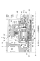
- FIG. 1 is a diagram illustrating a power transmission device 1 according to the first embodiment.
- FIG. 2A is an enlarged view of the power transmission device 1 around the counter gear 5.
- FIG. 2B is a diagram for explaining the region Rx in which the actuator ACT is arranged, and is an enlarged view showing a cross section of AA in FIG. 2A. In FIG. 2B, the member located on the inner diameter side of the clutch drum 48 is not shown.
- the transmission mechanism 3, the counter gear 5, the differential device 6, the drive shaft 8 (8A, 8B), and the drive shaft 8 (8A, 8B) are arranged along the transmission path of the output rotation of the motor 2. Is provided.
- the output rotation of the motor 2 is changed by the speed change mechanism 3, then decelerated by the counter gear 5 and transmitted to the differential device 6.
- the transmitted rotation is transmitted to the left and right drive wheels (not shown) of the vehicle on which the power transmission device 1 is mounted via the drive shafts 8 (8A, 8B).
- the drive shaft 8A is rotatably connected to the left wheel of the vehicle equipped with the power transmission device 1
- the drive shaft 8B is rotatably connected to the right wheel.
- the transmission mechanism 3 is connected to the downstream of the motor 2
- the counter gear 5 is connected to the downstream of the transmission mechanism 3
- the differential device 6 is connected to the downstream of the counter gear 5.
- Drive shafts 8 (8A, 8B) are connected downstream of the differential device 6.
- the motor housing 10, the outer cover 11, the inner cover 12, the outer case 13, and the inner case 14 constitute the main body case 9 of the power transmission device 1.
- the motor housing 10, the outer cover 11, and the inner cover 12 constitute a case (first case member) for the motor 2.
- the outer case 13 and the inner case 14 form a case (second case member) for accommodating the transmission mechanism 3, the counter gear 5, and the differential device 6.
- the space Sa formed between the outer cover 11 and the inner cover 12 on the inner diameter side of the motor housing 10 is a motor chamber for accommodating the motor 2.
- the space formed between the outer case 13 and the inner case 14 is divided into a space Sb for accommodating the counter gear 5 and the differential device 6 by a partition wall 142 provided in the inner case 14. It is partitioned into a space Sc that houses the mechanism 3. Therefore, the space Sb is a first gear chamber that accommodates the counter gear 5 and the differential device 6, and the space Sc is a second gear chamber that accommodates the transmission mechanism 3.
- the motor 2 has a cylindrical motor shaft 20, a cylindrical rotor core 21 extrapolated to the motor shaft 20, and a stator core 25 that surrounds the outer periphery of the rotor core 21 at predetermined intervals. ing.
- the motor shaft 20 is a tubular member having an insertion hole 200 for the drive shaft 8B, and the motor shaft 20 is extrapolated to the drive shaft 8B.
- the connecting portion 201 on the one end 20a side in the longitudinal direction and the supported portion 202 on the other end 20b side are intermediate between the connecting portion 201 and the supported portion 202 in the rotation axis X direction. It is formed with an inner diameter larger than the region 203.
- the inner circumference of the connecting portion 201 and the inner circumference of the supported portion 202 are supported by needle bearings NB and NB extrapolated to the drive shaft 8B.
- the motor shaft 20 is provided so as to be rotatable relative to the drive shaft 8B.
- bearings B1 and B1 are extrapolated and fixed to the outer circumference of the connecting portion 201 on the one end 20a side and the outer circumference of the supported portion 202 on the other end 20b side.
- One end 20a side of the motor shaft 20 is supported by a motor support portion 121 located on the inner diameter side of the inner cover 12 via a bearing B1.
- the other end 20b side of the motor shaft 20 is supported by the motor support portion 111 located on the inner diameter side of the outer cover 11 via the bearing B1.
- the motor housing 10 that surrounds the outer periphery of the rotor core 21 at predetermined intervals has a cylindrical peripheral wall portion 101.
- seal rings SL and SL are provided at one end 10a and the other end 10b in the rotation axis X direction.
- One end 10a of the motor housing 10 is joined to the annular joint portion 120 of the inner cover 12 without a gap by the seal ring SL provided at the one end 10a.
- the other end 10b of the motor housing 10 is joined to the annular joint 110 of the outer cover 11 without a gap by the seal ring SL provided on the other end 10b.
- the motor support portion 121 on the inner cover 12 side is arranged on the inner diameter side of the coil end 253a, which will be described later, with one end portion 21a of the rotor core 21 facing each other with a gap in the rotation axis X direction.
- the motor support portion 111 on the outer cover 11 side is arranged on the inner diameter side of the coil end 253b, which will be described later, with the other end portion 21b of the rotor core 21 facing each other with a gap in the rotation axis X direction.
- the rotor core 21 is arranged between the motor support portion 111 on the outer cover 11 side and the motor support portion 121 on the inner cover 12 side.
- the rotor core 21 is formed by laminating a plurality of silicon steel plates, and each of the silicon steel plates is extrapolated to the motor shaft 20 in a state where the relative rotation with the motor shaft 20 is restricted.
- the silicon steel plate When viewed from the rotation axis X direction of the motor shaft 20, the silicon steel plate has a ring shape, and on the outer peripheral side of the silicon steel plate, magnets of N pole and S pole (not shown) alternate in the circumferential direction around the rotation axis X. It is provided in.
- One end 21a of the rotor core 21 in the X direction of the rotation axis is positioned by the large diameter portion 204 of the motor shaft 20.
- the other end 21b of the rotor core 21 is positioned by a stopper 23 press-fitted into the motor shaft 20.
- the stator core 25 is formed by laminating a plurality of electromagnetic steel plates, and each of the electromagnetic steel plates has a ring-shaped yoke portion 251 fixed to the inner circumference of the motor housing 10 and a rotor core from the inner circumference of the yoke portion 251. It has a teeth portion 252 that protrudes to the 21 side.
- a stator core 25 having a configuration in which the winding 253 is distributed and wound across a plurality of tooth portions 252 is adopted, and the stator core 25 is a coil end 253a, 253b protruding in the rotation axis X direction.
- the length in the rotation axis X direction is longer than that of the rotor core 21 by the amount.
- stator core having a configuration in which windings are centrally wound may be adopted for each of the plurality of tooth portions 252 protruding toward the rotor core 21 side.
- one end 20a of the motor shaft 20 penetrates the motor support portion 121 of the inner cover 12 to the transmission mechanism 3 side (right side in the drawing) and is located in the space Sc.
- a lip seal RS is installed on the inner circumference of the motor support portion 121.
- the lip seal RS seals a gap between the inner circumference of the motor support portion 121 and the outer circumference of the motor shaft 20.
- the lip seal RS is provided to partition the space Sa on the inner diameter side of the motor housing 10 and the space Sc on the inner diameter side of the inner case 14 to prevent oil OL from entering the space Sa from the space Sc side. Has been done.
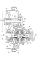
- FIG. 3 is a diagram illustrating a speed change mechanism 3.
- a speed change mechanism 3 is arranged in the space Sc.
- the speed change mechanism 3 has a planetary gear set 4, a clutch 47, and a band brake 49.
- the planetary gear set 4 has a sun gear 41, a ring gear 42, a pinion gear 43, a pinion shaft 44, and a carrier 45.
- the components of the planetary gear set 4 (sun gear 41, ring gear 42, pinion gear 43, pinion shaft 44, carrier 45) are provided on the inner diameter side of the outer wall portion 481 of the clutch drum 48.
- the clutch 47 includes a drive plate 471 (inner diameter side friction plate) spline-fitted on the outer circumference of the ring gear 42 and a driven plate 472 (outer diameter side friction plate) spline-fitted on the inner circumference of the outer wall portion 481 of the clutch drum 48. And a piston 475 provided so as to be movable in the direction of the rotation axis.
- the clutch drum 48 has an outer wall portion 481, a disk portion 480, an inner wall portion 482, and a connecting portion 483.
- the outer wall portion 481 has a tubular shape that surrounds the rotation shaft X at predetermined intervals.
- the disk portion 480 extends from the end portion of the outer wall portion 481 on the differential device 6 side (right side in the drawing) to the inner diameter side.
- the region on the inner diameter side of the disk portion 480 is a recess 480a recessed in the direction away from the planetary gear set 4.
- the inner wall portion 482 is formed in a tubular shape that surrounds the rotation shaft X at predetermined intervals.
- the inner wall portion 482 extends from the inner diameter side end of the disk portion 480 to the planetary gear assembly 4 side (left side in the drawing), and the tip of the inner wall portion 482 is at the meshing portion between the sun gear 41 and the pinion gear 43. , They face each other with a gap in the X direction of the rotation axis.
- the connecting portion 483 has a cylindrical shape that surrounds the rotation shaft X at predetermined intervals.
- the base end portion 483a in the longitudinal direction is connected to the inner circumference on the distal end side of the inner wall portion 482.
- the connecting portion 483 extends linearly on the extension of the connecting portion 201 of the motor shaft 20 in a direction approaching the motor 2 (to the left in the drawing).
- the tip 483b of the connecting portion 483 is located closer to the motor 2 than the outer wall portion 481.
- the clutch drum 48 composed of the outer wall portion 481, the disk portion 480, the inner wall portion 482, and the connecting portion 483 is provided with an opening facing the motor 2 side, and the connecting portion located on the inner diameter side.
- the sun gear 41 of the planetary gear set 4 is spline-fitted on the outer circumference of the 483.
- the ring gear 42 is located on the outer diameter side of the sun gear 41.
- the ring gear 42 includes a peripheral wall portion 421 that surrounds the outer periphery of the sun gear 41 at predetermined intervals, a disc portion 422 that extends from the end of the peripheral wall portion 421 on the motor 2 side to the inner diameter side, and an end portion of the disc portion 422 on the inner diameter side. It has a connecting portion 423 extending from the motor 2 side to the motor 2.
- the connecting portion 423 has a ring shape that surrounds the rotating shaft X at predetermined intervals, and a connecting portion 201 on the one end 20a side of the motor shaft 20 is spline-fitted on the inner circumference of the connecting portion 423.
- the peripheral wall portion 421 located on the outer diameter side of the connecting portion 423 meshes with the outer circumference of the pinion gear 43 on the inner circumference of the region located on the outer diameter side of the sun gear 41.
- the pinion gear 43 meshes with the inner circumference of the peripheral wall portion 421 of the ring gear 42 and the outer circumference of the sun gear 41.
- the pinion shaft 44 that supports the pinion gear 43 is provided in a direction along an axis X3 parallel to the rotation shaft X.
- One end and the other end of the pinion shaft 44 are supported by a pair of side plate portions 451 and 452 constituting the carrier 45.
- the side plate portions 451 and 452 are provided parallel to each other at intervals in the axis X3 direction.
- One side plate portion 452 located on the motor 2 side extends from the other side plate portion 451 to the rotation axis X side.
- a tubular connecting portion 453 that surrounds the rotation shaft X at predetermined intervals is integrally formed at the end portion 452a on the inner diameter side of the side plate portion 452.
- the connecting portion 453 extends on the rotating shaft X side (inner diameter side) of the connecting portion 201 of the motor shaft 20 in a direction away from the motor 2 along the rotating shaft X.
- the connecting portion 453 is provided so as to cross the inner diameter side of the sun gear 41 from the motor 2 side to the differential device 6 side, and the connecting portion 453 is connected to the hollow shaft 50 on the inner diameter side of the inner wall portion 482 of the clutch drum 48.
- a spline is fitted to the inner circumference of the portion 501.
- a driven plate 472 of the clutch 47 is spline-fitted on the inner circumference of the outer wall portion 481 of the clutch drum 48.
- the drive plate 471 of the clutch 47 is spline-fitted to the outer periphery of the peripheral wall portion 421 of the ring gear 42.
- Drive plates 471 and driven plates 472 are alternately provided between the peripheral wall portion 421 of the ring gear 42 and the outer wall portion 481 of the clutch drum 48.
- the retaining plate 473 positioned by the snap ring 474 is located on the motor 2 side of the region where the drive plate 471 and the driven plate 472 are alternately provided, and the piston 475 is located on the differential device 6 side.
- the pressing portion 475a is located.
- the base portion 475b on the inner diameter side of the piston 475 is provided at a position farther from the planetary gear set 4 than the pressing portion 475a on the outer diameter side.
- the base portion 475b on the inner diameter side of the piston 475 is interpolated into the recess 480a on the inner diameter side of the disc portion 480 adjacent in the rotation axis X direction.
- a spring Sp supported by the spring retainer 476 is pressed against the surface of the base portion 475b on the motor 2 side (left side in the drawing) from the rotation axis X direction.
- the piston 475 is urged toward the differential device 6 by an urging force acting from the spring Sp.
- a protruding portion 484 protruding toward the differential device 6 is provided at the boundary between the recess 480a and the inner wall portion 482.
- the protrusion 484 is inserted into the inner circumference of the first support portion 141 of the bearing B3.
- An oil OL supply path 141a is open on the inner circumference of the first support portion 141.
- An oil passage 484a for guiding the oil OL supplied from the first support portion 141 side into the recess 480a of the clutch drum 48 is provided inside the protrusion 484.
- the oil OL supplied through the oil passage 484a is supplied to the oil chamber between the base portion 475b of the piston 475 and the recess 480a to displace the piston 475 toward the motor 2.
- the drive plate 471 and the driven plate 472 of the clutch 47 are gripped between the pressing portion 475a of the piston 475 and the retaining plate 473.
- the relative rotation between the ring gear 42 to which the drive plate 471 is spline-fitted and the clutch drum 48 to which the driven plate 472 is spline-fitted is regulated according to the pressure of the supplied oil OL, and finally. Relative rotation is regulated.
- a band brake 49 is wound around the outer wall portion 481 of the clutch drum 48.
- the actuator ACT see FIG. 2
- the rotation of the clutch drum 48 around the rotation axis X is restricted.
- the inner case 14 accommodating the transmission mechanism 3 is located on the outer diameter side from the connection portion between the outer peripheral wall 147 surrounding the outer circumference of the transmission mechanism 3 at predetermined intervals and the outer peripheral wall 147 and the partition wall 142. It has an extending side wall 143 and a peripheral wall portion 144.
- the side wall 143 extends radially outward of the rotation axis X on the extension of the partition wall 142, and the end portion of the side wall 143 on the outer diameter side communicates with the peripheral wall portion 144 that surrounds the outer circumference of the counter gear 5 at predetermined intervals. ing.
- a joint portion 140 with the inner cover 12 is provided at the tip portion on the inner cover 12 side (left side in the drawing), and the joint portion 140 is joined to the inner cover 12 from the rotation axis X direction. There is.
- the actuator ACT of the band brake 49 is provided in a region Rx on the outer diameter side of the outer peripheral wall 147, which overlaps the side wall 143 in the rotation axis X direction.
- the region where the actuator ACT is provided has a positional relationship that overlaps with the side wall 143.
- the actuator ACT has a shaft portion 495 that rotates by the rotational driving force of a drive motor (not shown).
- the tip end side of the shaft portion 495 penetrates a connection piece 491 provided at one end in the circumferential direction of the band brake 49, a connection piece 492 provided at the other end, and a fixing piece 16 provided in the inner case 14.
- the planetary gear set 4 and the clutch 47 are located on the inner diameter side of the band brake 49.
- the actuator ACT, the band brake 49, the planetary gear set 4, and the clutch 47 overlap in the radial direction of the rotating shaft X, and when viewed from the radial outside of the rotating shaft X, the actuator ACT, the band brake 49, and the clutch 47 overlap.
- the planetary gear set 4 and the clutch 47 are provided in an overlapping positional relationship.
- the ring gear 42 of the planetary gear set 4 is the input unit for the output rotation of the motor 2, and the carrier 45 is the output unit for the input rotation.
- the speed change mechanism 3 is designed to switch between the low speed stage and the high speed stage by changing the combination of engaging / releasing the clutch 47 and operating the band brake 49.
- the speed change mechanism 3 can be switched between the low speed stage and the high speed stage.
- the low speed stage is realized under the following condition (a), and the high speed stage is realized under the condition (b).
- the transmission mechanism 3 is a two-stage transmission mechanism, and the low-speed stage and the high-speed stage rotate in the same manner. The direction (forward or reverse). Forward / backward switching is possible by forward / reverse rotation of the motor 2.
- the output rotation of the motor 2 is output to the hollow shaft 50 to which the connecting portion 453 of the carrier 45 is connected after the speed is changed by the transmission mechanism 3.
- one end 50a in the longitudinal direction has a gap in the rotation axis X direction in the bearing B5 that supports the support portion 601 of the differential case 60. It is provided with a space.
- the other end 50b of the hollow shaft 50 is a connecting portion 501 with the planetary gear set 4.
- the outer circumference of the connecting portion 501 is supported by a needle bearing NB interposed between the inner wall portion 482 of the clutch drum 48.
- a gear portion 502 is integrally formed on the outer periphery of the hollow shaft 50 on the one end 50a side.
- Bearings B3 and B3 are extrapolated on both sides of the gear portion 502.
- the bearing B3 on one end 50a side is supported by the support portion 151 on the inner case 14 side, and the bearing B3 on the other end 50b side is supported by the first support portion 141 on the inner case 14.
- a large-diameter gear 52 of the counter gear 5 meshes with the outer circumference of the gear portion 502 so that rotation can be transmitted.
- the large-diameter gear 52 is spline-fitted on the outer circumference of the cylindrical hollow shaft portion 51.
- Bearings B4 are extrapolated to one end 51a and the other end 51b of the hollow shaft portion 51 in the longitudinal direction.
- the bearing B4 extrapolated to one end portion 51a of the hollow shaft portion 51 is inserted into the cylindrical second support portion 135 of the outer case 13.
- One end portion 51a of the hollow shaft portion 51 is rotatably supported by a second support portion 135 of the outer case 13 via a bearing B4.
- the bearing B4 extrapolated to the other end 51b of the hollow shaft 51 is inserted into the cylindrical second support 145 of the inner case 14.
- the other end portion 51b of the hollow shaft portion 51 is rotatably supported by the second support portion 145 of the inner case 14 via the bearing B4.
- the hollow shaft portion 51 of the counter gear 5 is provided along the axis X1 parallel to the rotation shaft X.
- a park gear 53 is provided adjacent to one end portion 51a side (left side in the drawing) when viewed from the large diameter gear 52.
- a small diameter gear portion 511 is provided at a position away from one end portion 51a side (right side in the drawing) when viewed from the park gear 53.
- the small-diameter gear portion 511 is formed integrally with the hollow shaft portion 51 and has an outer diameter R2 smaller than the outer diameter R1 of the large-diameter gear 52 (see FIG. 4: R1> R2).
- the small-diameter gear portion 511 meshes with the final gear FG fixed to the differential case 60 of the differential device 6 so as to be able to transmit rotation.
- the output rotation of the motor 2 is input to the hollow shaft 50 via the transmission mechanism 3.
- the rotation input to the hollow shaft 50 is input to the counter gear 5 via the large-diameter gear 52 meshed with the gear portion 502 of the hollow shaft 50.
- the large-diameter gear 52 and the park gear 53 are spline-fitted on the outer periphery of the hollow shaft portion 51, and the small-diameter gear portion 511 is integrally formed with the hollow shaft portion 51. Therefore, when the output rotation of the motor 2 is input to the counter gear 5, the park gear 53 and the small-diameter gear portion 511 rotate together with the large-diameter gear 52 around the axis X1.
- the differential case 60 rotates around the rotation axis X in conjunction with the rotation of the counter gear 5 around the axis X1. To do.
- the outer diameter R2 of the small diameter gear portion 511 is smaller than the outer diameter R1 of the large diameter gear 52 (see FIG. 4).
- the large-diameter gear 52 serves as an input unit for rotation transmitted from the motor 2 side
- the small-diameter gear unit 511 serves as an output unit for the transmitted rotation. Then, the rotation input to the counter gear 5 is greatly decelerated and then output to the differential case 60.
- FIG. 4 is an enlarged view of the power transmission device 1 around the differential device 6.
- the differential case 60 is formed in a hollow shape for accommodating the shaft 61, the bevel gears 62A and 62B, and the side gears 63A and 63B.
- tubular support portions 601 and 602 are provided on both sides of the rotation axis X direction (left-right direction in the drawing). The support portions 601 and 602 extend along the rotation axis X in a direction away from the shaft 61.
- Bearing B5 is extrapolated to the support portion 602 of the differential case 60.
- the bearing B5 extrapolated to the support portion 602 is held by the ring-shaped first support portion 131 of the outer case 13.
- a drive shaft 8A penetrating the opening 130 of the outer case 13 is inserted into the support portion 602 from the rotation axis X direction, and the drive shaft 8A is rotatably supported by the support portion 602.
- a lip seal RS is fixed to the inner circumference of the opening 130, and the lip portion (not shown) of the lip seal RS elastically contacts the outer circumference of the drive shaft 8A to open the outer circumference of the drive shaft 8A.
- the gap between the inner circumference and the inner circumference of the portion 130 is sealed.
- a bearing B5 is extrapolated to the support portion 601 of the differential case 60.
- the support portion 601 of the differential case 60 is rotatably supported by the support portion 151 of the support member 15 fixed to the inner case 14 via the bearing B5.
- the bearing B5 extrapolated to the support portion 601 is held by the ring-shaped support portion 151 of the support member 15.
- the support member 15 extends from the outer circumference of the support portion 151 to the motor 2 side (left side in the drawing), and the opening on the tip end side of the tubular portion 152 over the entire circumference. It has a flange portion 153 that surrounds it.
- the flange portion 153 of the support member 15 is fixed to the first support portion 141 of the inner case 14 by a bolt B penetrating the flange portion 153.
- the support portion 601 of the differential case 60 is rotatably supported by the support member 15 via the bearing B5.
- the support member 15 is fixed to the inner case 14. Therefore, the support portion 601 of the differential case 60 is supported by the inner case 14 which is a fixed side member via the bearing B5 and the support member 15.
- a drive shaft 8B penetrating the opening 114 of the outer cover 11 is inserted into the support portion 601 of the differential case 60 from the rotation axis X direction.
- the drive shaft 8B is provided across the motor shaft 20 of the motor 2, the planetary gear set 4, and the inner diameter side of the hollow shaft 50 in the rotation axis X direction, and the tip end side of the drive shaft 8B is a support portion 601. It is rotatably supported.
- a lip seal RS is fixed to the inner circumference of the opening 114 of the outer cover 11, and the lip portion (not shown) of the lip seal RS elastically contacts the outer circumference of the drive shaft 8B, so that the drive shaft 8B The gap between the outer circumference of the shaft and the inner circumference of the opening 114 is sealed.
- side gears 63A and 63B are spline-fitted on the outer periphery of the tip of the drive shaft 8 (8A, 8B), and the side gears 63A and 63B and the drive shaft 8 (8A) are fitted. , 8B) are integrally rotatably connected around the rotation axis X.
- the differential case 60 is provided with shaft holes 60a and 60b penetrating in a direction orthogonal to the rotation axis X at positions symmetrical with respect to the rotation axis X.
- the shaft holes 60a and 60b are located on the axis Y orthogonal to the rotation axis X, and the shaft 61 is inserted into the shaft holes 60a and 60b.
- the shaft 61 is fixed to the differential case 60 with a pin P, and the shaft 61 is prohibited from rotating around the axis Y.
- the shaft 61 is located between the side gears 63A and 63B in the differential case 60, and is arranged along the axis Y.
- bevel gears 62A and 62B are externally inserted and rotatably supported on the shaft 61.
- Two bevel gears 62A and 62B are provided at intervals in the longitudinal direction (axis Y direction) of the shaft 61, and the bevel gears 62A and 62B are arranged so that their teeth face each other. ..
- the bevel gears 62A and 62B are provided so that the axes of the bevel gears 62A and 62B are aligned with the axes of the shaft 61.
- side gears 63A and 63B are located on both sides of the bevel gears 62A and 62B in the rotation axis X direction.
- Two side gears 63A and 63B are provided with their teeth facing each other at intervals in the X direction of the rotation axis, and the bevel gears 62A and 62B and the side gears 63A and 63B have teeth of each other. Is assembled in a meshed state.
- the transmission mechanism 3 As shown in FIG. 1, in the power transmission device 1, the transmission mechanism 3, the counter gear 5, the differential device 6, and the drive shaft 8 (8A, 8B) are arranged along the transmission path of the output rotation of the motor 2. , Are provided.
- the rotation is input to the transmission mechanism 3 via the motor shaft 20 that rotates integrally with the rotor core 21.
- the ring gear 42 of the planetary gear set 4 serves as a rotation input unit
- the carrier 45 serves as a rotation output unit.
- the rotation input to the speed change mechanism 3 is output from the connecting portion 453 of the carrier 45 to the hollow shaft 50 after the speed change. Then, the rotation input to the hollow shaft 50 is input to the counter gear 5 via the large diameter gear 52 meshed with the gear portion 502 of the hollow shaft 50.
- the large-diameter gear 52 that meshes with the gear portion 502 of the hollow shaft 50 serves as an input unit for the output rotation of the motor 2, and the small-diameter gear portion 511 that meshes with the final gear FG of the differential case 60 inputs. It is the output part of the rotation.
- the outer diameter R2 of the small diameter gear portion 511 is smaller than the outer diameter R1 of the large diameter gear 52 (see FIG. 4). Therefore, the rotation input to the counter gear 5 is greatly decelerated and then output to the differential case 60 (differential device 6) via the final gear FG in which the small diameter gear portion 511 meshes.
- the drive shaft 8 (8A, 8B) rotates around the rotation axis X by rotating the differential case 60 around the rotation axis X by the input rotation.
- the output rotation of the motor 2 is transmitted to the left and right drive wheels (not shown) of the vehicle on which the power transmission device 1 is mounted.
- the actuator ACT of the band brake 49 is a region Rx on the outer diameter side of the outer peripheral wall 147 that surrounds the outer circumference of the transmission mechanism 3 at predetermined intervals, and overlaps the side wall 143 and the rotation axis X direction. It is provided in the area to be wrapped (see FIG. 2).
- the region of the side wall 143 that houses the counter gear 5 projects outward in the radial direction of the rotation axis X. Therefore, on the outer diameter side of the outer peripheral wall 147, there is a spatial margin in the region Rx overlapping the side wall 143 when viewed from the rotation axis X direction.
- the region Rx and providing the actuator ACT of the band brake 49 it is not necessary to increase the size of the main body case 9 of the power transmission device 1. ..
- the motor shaft 20 of the rotor core 21, the counter gear 5, and the drive shafts 8 (8A, 8B) are arranged in series on the transmission path of the output rotation of the motor 2.
- a drive shaft 8B is provided so as to penetrate the inner diameter side of the motor shaft 20 in the rotation axis X direction, and the drive shaft 8B and the motor shaft 20 are provided so as to be relatively rotatable on a common rotation shaft X. ing. Therefore, compared to a power transmission device in which the motor shaft, the counter gear, and the drive shaft are provided on different rotation axes parallel to each other, that is, a so-called three-axis type power transmission device, the direction of the rotation axis is larger. The size can be suppressed.
- the power transmission device 1 has the following configuration.
- the power transmission device 1 is Motor 2 and The transmission mechanism 3 connected to the downstream of the motor 2 and A counter gear 5 (reduction gear) arranged downstream of the transmission mechanism 3 and A main body case 9 (case member) that houses the motor 2, the transmission mechanism 3, and the counter gear 5.
- the speed change mechanism 3 includes a band brake 49 and an actuator ACT that drives the band brake 49.
- the main body case 9 (case member) An outer peripheral wall 147 that surrounds the radial outer circumference of the transmission mechanism 3 and It has a side wall 143 that is connected to the outer peripheral wall 147 and extends radially outward from the outer peripheral wall 147.
- the actuator ACT is adjacent to the outer peripheral wall 147 and adjacent to the side wall 143.
- the region Rx in the inner case 14 of the main body case 9 there is a spatial margin in the region Rx on the outer diameter side of the outer peripheral wall 147 and overlapping the side wall 143 when viewed from the rotation axis X direction.
- This region Rx is located outside the region where the outer peripheral wall 147 and the side wall 143 in the inner case 14 are connected in a substantially L-shaped cross section, and the region Rx in the main body case 9 is the outer peripheral wall 147 and the side wall 143. It is an available space between the inner cover 12 and the inner cover 12.
- the actuator ACT in the power transmission device 1 is expanded in the rotation axis X direction and the radial direction of the power transmission device 1. Instead, an actuator ACT can be provided.
- the power transmission device 1 has the following configuration. (2) In the rotation axis X direction of the motor 2, the side wall 143 is arranged so as to be sandwiched between the actuator ACT and the counter gear 5 (reduction gear). The side wall 143, the actuator ACT, and the counter gear 5 overlap in the rotation axis X direction of the motor 2, and are provided in a positional relationship in which the side wall 143, the actuator ACT, and the counter gear 5 overlap when viewed from the rotation axis X direction. ing.
- the power transmission device 1 has the following configuration.
- the band brake 49 and the actuator ACT are arranged adjacent to the outer peripheral wall 147 with the outer peripheral wall 147 in between in the radial direction of the rotation axis X of the motor 2.
- the band brake 49, the actuator ACT, and the outer peripheral wall 147 overlap in the radial direction of the rotating shaft X, and when viewed from the radial direction of the rotating shaft X, the positional relationship in which the band brake 49, the actuator ACT, and the outer peripheral wall 147 overlap. It is provided in.
- FIG. 5 is a diagram for explaining the power transmission device 1A according to the second embodiment.
- FIG. 6 is an enlarged view of the power transmission device 1A around the speed change mechanism 3A.
- FIG. 7 is a diagram illustrating a region Rx in which the actuator ACT in the power transmission device 1A is arranged.
- the power transmission device 1A includes a motor 2, a transmission mechanism 3A, a counter gear 5 that transmits the output rotation of the transmission mechanism 3A to the differential device 6, and a drive shaft 8 (8A) that transmits the transmitted rotation. , 8B) and a differential device 6.
- a transmission mechanism 3A, a counter gear 5, a differential device 6, and a drive shaft 8 (8A, 8B) are provided along the transmission path of the output rotation of the motor 2.
- the output rotation of the motor 2 is changed by the speed change mechanism 3A, then decelerated by the counter gear 5 and transmitted to the differential device 6.
- the transmitted rotation is transmitted to the left and right drive wheels (not shown) of the vehicle on which the power transmission device 1A is mounted via the drive shafts 8 (8A, 8B).
- the transmission mechanism 3A is connected to the downstream of the motor 2
- the counter gear 5 is connected to the downstream of the transmission mechanism 3A
- the differential device 6 is connected to the downstream of the counter gear 5.
- Drive shafts 8 (8A, 8B) are connected downstream of the differential device 6.
- the motor 2 and the transmission mechanism 3A are coaxially arranged on the common rotation shaft Xa.
- the rotary shaft Xb of the counter gear 5 and the rotary shafts Xc of the differential device 6 and the drive shafts 8 (8A, 8B) are provided parallel to the rotary shaft Xa.
- the power transmission device 1A is a so-called three-axis type power transmission device in which the rotation axes Xa, Xb, and Xc involved in the transmission of rotation are arranged so as to be parallel to each other.
- the main body case 9 of the power transmission device 1A is configured by the motor housing 10, the outer cover 11, the inner cover 12, the outer case 13, and the inner case 14.
- the motor housing 10, the outer cover 11, and the inner cover 12 constitute a case (first case member) for the motor 2.
- the outer case 13 and the inner case 14 form a case (second case member) for accommodating the transmission mechanism 3A, the counter gear 5, and the differential device 6.
- the motor 2 has a cylindrical motor shaft 20, a cylindrical rotor core 21 extrapolated to the motor shaft 20, and a stator core 25 that surrounds the outer circumference of the rotor core 21 at predetermined intervals.
- bearings B1 and B1 are extrapolated on both sides of the rotor core 21.
- the motor shaft 20 is rotatably supported by the motor support portion 111 of the outer cover 11 and the motor support portion 121 of the inner cover 12 via bearings B1 and B1.
- one end 20a side of the motor shaft 20 is provided with a connecting portion 201 having an outer diameter smaller than that of the large diameter portion 208 on the other end 20b side.
- the connecting portion 201 of the motor shaft 20 is spline-fitted to the inner circumference of the connecting portion 423 on the transmission mechanism 3A side in the ring-shaped third support portion 148 of the inner case 14.
- the speed change mechanism 3A includes a planetary gear set 4, a clutch 47, and a band brake 49.
- the planetary gear set 4 has a sun gear 41, a ring gear 42, a pinion gear 43, a pinion shaft 44, and a carrier 45.
- the components of the planetary gear set 4 (sun gear 41, ring gear 42, pinion gear 43, pinion shaft 44, carrier 45) are provided on the inner diameter side of the outer wall portion 481 of the clutch drum 48.
- the clutch 47 includes a drive plate 471 (inner diameter side friction plate) spline-fitted on the outer circumference of the ring gear 42 and a driven plate 472 (outer diameter side friction plate) spline-fitted on the inner circumference of the outer wall portion 481 of the clutch drum 48. And a piston 475 provided so as to be movable in the rotation axis Xa direction.
- the clutch drum 48 has an outer wall portion 481, a disk portion 480, an inner wall portion 482, and a connecting portion 483.
- the outer wall portion 481 has a tubular shape that surrounds the rotation shaft Xa at predetermined intervals.
- the disk portion 480 extends from the end portion of the outer wall portion 481 opposite to the motor 2 (left side in the drawing) to the inner diameter side.
- An inner wall portion 482 is provided at an end portion on the inner diameter side of the disk portion 480.
- the inner wall portion 482 is formed in a tubular shape that surrounds the rotation shaft Xa at predetermined intervals.
- the inner wall portion 482 extends from the end on the inner diameter side of the disk portion 480 to the planetary gear assembly 4 side (right side in the drawing), and the tip of the inner wall portion 482 is located on the inner diameter side of the band brake 49. ..
- the connecting portion 483 has a cylindrical shape that surrounds the rotation shaft Xa at predetermined intervals.
- the base end portion 483a in the longitudinal direction is connected to the inner circumference on the distal end side of the inner wall portion 482.
- the connecting portion 483 extends linearly in a direction approaching the motor 2 (to the right in the drawing).
- the clutch drum 48 composed of the outer wall portion 481, the disk portion 480, the inner wall portion 482, and the connecting portion 483 is provided with an opening facing the motor 2 side.
- the support shaft 30 is a shaft-shaped member in which a small diameter portion 301 and a large diameter portion 302 are integrally formed by arranging them in the direction of the rotation axis Xa, and is arranged in a direction along the rotation axis Xa. ing.
- the support shaft 30 is arranged coaxially with the motor shaft 20. As shown in FIG. 6, in the large diameter portion 302 located on the motor 2 side (right side in the drawing) of the support shaft 30, an accommodating hole 302a capable of receiving the motor shaft 20 is opened in a portion facing the motor shaft 20. doing.
- a shaft portion 424 provided at the tip of the motor shaft 20 is inserted into the accommodating hole 302a.
- a needle bearing NB extrapolated to the shaft portion 424 is in contact with the inner circumference of the accommodating hole 302a, and the support shaft 30 and the motor shaft 20 are rotatably engaged with each other at the accommodating hole 302a.
- a disc-shaped flange portion 303 is integrally formed at the end of the large diameter portion 302 on the motor 2 side.
- the flange portion 303 is provided in a direction orthogonal to the rotation axis Xa, and the outer circumference of the flange portion 303 extends to the side of the connecting portion 483 of the clutch drum 48.
- a sun gear 41 of the planetary gear set 4 is spline-fitted on the outer circumference of the connecting portion 483.
- the ring gear 42 is located on the outer diameter side of the sun gear 41.
- the ring gear 42 includes a peripheral wall portion 421 that surrounds the outer periphery of the sun gear 41 at predetermined intervals, a disc portion 422 that extends from the end of the peripheral wall portion 421 on the motor 2 side to the inner diameter side, and a motor 2 from the inner diameter side of the disc portion 422. It has a connecting portion 423 extending to the side and a shaft portion 424 extending from the inner diameter side end of the disc portion 422 to the side opposite to the motor 2.
- the outer circumference of the pinion gear 43 meshes with the inner circumference of the region located on the outer diameter side of the sun gear 41.
- the pinion gear 43 meshes with the inner circumference of the peripheral wall portion 421 on the ring gear 42 side and the outer circumference of the sun gear 41.
- the pinion shaft 44 that supports the pinion gear 43 is provided in a direction along an axis X3 parallel to the rotation shaft Xa of the motor 2.
- One end and the other end of the pinion shaft 44 are supported by a pair of side plate portions 451 and 452 constituting the carrier 45.
- the side plate portions 451 and 452 are provided parallel to each other at intervals in the axis X3 direction.
- One side plate portion 452 located on the motor 2 side extends to the rotation axis Xa side from the other side plate portion 451.
- the inner diameter side end portion 452a of the side plate portion 452 is connected to the outer circumference of the flange portion 303 on the support shaft 30 side.
- the peripheral wall portion 421 of the ring gear 42 has a ring shape that surrounds the rotation shaft Xa at predetermined intervals, and the drive plate 471 of the clutch 47 is spline-fitted on the outer periphery of the peripheral wall portion 421.
- the driven plate 472 of the clutch 47 is spline-fitted to the inner circumference of the outer wall portion 481 of the clutch drum 48.
- Drive plates 471 and driven plates 472 are alternately provided between the peripheral wall portion 421 of the ring gear 42 and the outer wall portion 481 of the clutch drum 48.
- a retaining plate 473 positioned by the snap ring 474 is located on the motor 2 side of the region where the drive plate 471 and the driven plate 472 are alternately provided, and the piston 475 is located on the opposite side of the motor 2.
- the pressing portion 475a of the above is located.
- the piston 475 has a base portion 475b provided in a direction orthogonal to the rotation axis Xa.
- a tubular wall portion 475c extending toward the planetary gear assembly 4 side (right side in the drawing) is provided at a substantially central portion of the base portion 475b in the radial direction of the rotating shaft Xa.
- a slit 475d recessed in a direction away from the disc portion 480 of the clutch drum 48 (in the right direction in the drawing) is provided in the region where the cylinder wall portion 475c is provided.
- a guide piece 480b extending from the disk portion 480 of the clutch drum 48 to the motor 2 side is inserted into the slit 475d.
- the spring Sp supported by the spring retainer 476 is pressed against the surface of the base portion 475b on the motor 2 side from the rotation axis X direction.
- the piston 475 is urged to the disk portion 480 side (left side in the drawing) of the clutch drum 48 by the urging force acting from the spring Sp.
- a protruding portion 484 projecting to the opposite side of the motor 2 is provided at the boundary between the disc portion 480 and the inner wall portion 482.
- the protrusion 484 is inserted into the inner circumference of the support portion 151 of the bearing B2.
- An oil OL supply path 151a is open on the inner circumference of the support portion 151.
- an oil passage 484a is provided inside the protrusion 484, to guide the oil OL supplied from the support portion 151 side to the oil chamber between the disk portion 480 of the clutch drum 48 and the base portion 475b of the piston 475. ing.
- the oil OL supplied to the oil chamber via the oil passage 484a displaces the piston 475 to the motor 2 side (right side in the figure). At this time, the displacement of the piston 475 in the rotation axis Xa direction is guided by the guide piece 480b provided on the disk portion 480 and the slit 475d on the piston 475 side into which the guide piece 480b is inserted.
- a band brake 49 is wound around the outer wall portion 481 of the clutch drum 48.
- the winding radius of the band brake 49 is narrowed by an actuator (not shown), the rotation of the clutch drum 48 around the rotation axis Xa is restricted.
- the motor housing 10 accommodating the motor 2 has a cylindrical peripheral wall portion 101.
- the peripheral wall portion 101 is provided at a position where it overlaps with the clutch 47 of the transmission mechanism 3A when viewed from the rotation axis Xa direction, and the peripheral wall portion 101 and the clutch 47 are provided in a positional relationship in which they overlap in the rotation axis Xa direction. ..
- the region on the rotation shaft Xa side (upper side in the drawing) is joined to the third support portion 148 of the inner case 14 from the rotation shaft Xa direction.
- the side wall 143 of the inner case 14 is located between the speed change mechanism 3A and the motor 2 (inner cover 12).
- the side wall 143 is provided in a direction orthogonal to the rotation axis Xa, and is provided with a gap between the inner cover 12 and the rotation axis Xa direction.
- a cylindrical second support portion 145 is provided on the inner circumference of a region on the outer diameter side with respect to the rotation shaft Xa of the speed change mechanism 3A.
- the second support portion 145 extends from the surface of the side wall 143 facing the outer case 13 (the left surface in the drawing) toward the outer case 13.
- the side wall 143 of the inner case 14 is provided with a range from a region located on the side of the transmission mechanism 3A to a region where the second support portion 145 is provided in a direction orthogonal to the rotation axis Xa and the rotation axis Xb. There is.
- the actuator ACT of the band brake 49 is provided in a region Rx on the outer diameter side of the peripheral wall portion 101 of the motor housing 10 and overlaps with the side wall 143 in the rotation axes Xa and Xb directions.
- the region where the actuator ACT is provided has a positional relationship that overlaps with the side wall 143.
- the planetary gear set 4 and the clutch 47 are located on the inner diameter side of the band brake 49.
- the band brake 49, the planetary gear set 4, and the clutch 47 overlap in the radial direction of the rotating shaft X, and when viewed from the radial outside of the rotating shaft X, the band brake 49, the planetary gear set 4, and the clutch 47 overlap.
- the clutch 47 and the clutch 47 are provided in an overlapping positional relationship.
- the ring gear 42 of the planetary gear set 4 is the input unit for the output rotation of the motor 2, and the carrier 45 is the output unit for the input rotation.
- the low speed stage is realized under the following condition (a), and the high speed stage is realized under the condition (b).
- the transmission mechanism 3A is a two-stage transmission mechanism, and the low-speed stage and the high-speed stage rotate in the same manner. The direction (forward or reverse). Forward / backward switching is possible by forward / reverse rotation of the motor 2.
- the output rotation of the motor 2 is output from the side plate portion 452 of the carrier 45 to the support shaft 30 after the speed is changed by the transmission mechanism 3A.
- the support shaft 30 extends along the rotation shaft Xa in a direction away from the motor 2.
- the hollow shaft 31 is spline-fitted on the outer circumference of the small diameter portion 301.
- bearings B2 and B2 are extrapolated on both sides in the direction of the rotating shaft Xa.
- the hollow shaft 31 is supported by a third support portion 138 on the outer case 13 side and a support portion 151 of the support member 15 via bearings B2 and B2. Therefore, the support shaft 30 is supported by the third support portion 138 on the outer case 13 side and the third support portion 148 on the inner case 14 side via the hollow shaft 31.
- the gear portion 311 is integrally formed on the outer periphery of the region between the bearings B2 and B2.
- a large-diameter gear 52 of the counter gear 5 meshes with the outer circumference of the gear portion 311 so as to be able to transmit rotation.
- the large-diameter gear 52 is spline-fitted on the outer circumference of the cylindrical hollow shaft portion 51.
- Bearings B3 and B3 are extrapolated to one end 51a and the other end 51b of the hollow shaft portion 51 in the longitudinal direction.
- One end portion 51a of the hollow shaft portion 51 is rotatably supported by a second support portion 135 of the outer case 13 via a bearing B3.
- the other end 51b of the hollow shaft 51 is rotatably supported by the second support 145 of the inner case 14 via the bearing B3.
- the hollow shaft portion 51 of the counter gear 5 is provided along the rotation shaft Xb parallel to the rotation shaft Xa.
- a small diameter gear portion 511 is provided adjacent to the other end portion 51b side (right side in the drawing) when viewed from the large diameter gear 52.
- the small-diameter gear portion 511 is formed integrally with the hollow shaft portion 51 and has an outer diameter R2 smaller than the outer diameter R1 of the large-diameter gear 52 (see FIG. 5: R1> R2).
- the small-diameter gear portion 511 meshes with the final gear FG fixed to the differential case 60 of the differential device 6 so as to be rotatable and transmittable.
- tubular support portions 601 and 602 are provided on both sides in the rotation axis Xc direction (left-right direction in the drawing).
- the support portions 601 and 602 extend along the rotation axis Xc parallel to the rotation axis Xa.
- Bearings B4 and B4 are extrapolated to the support portions 601 and 602 of the differential case 60.
- the support portion 602 is held by the ring-shaped first support portion 131 of the outer case 13 via the bearing B4.
- the support portion 602 is held by the ring-shaped first support portion 141 of the inner case 14 via the bearing B4.
- a drive shaft 8B penetrating the opening 146 of the inner case 14 is inserted into the support portion 601 of the differential case 60 from the direction of the rotation axis Xc.
- a drive shaft 8A penetrating the opening 130 of the outer case 13 is inserted into the support portion 602 of the differential case 60 from the direction of the rotation axis Xc.
- side gears 63A and 63B are spline-fitted on the outer periphery of the tip of the drive shaft 8 (8A, 8B).
- a columnar shaft 61 is provided along an axis Y orthogonal to the rotation axis Xc, and the side gears 63A and 63B face each other in the rotation axis Xc direction with the shaft 61 in between. ing.
- Bevel gears 62A and 62B are externally inserted and rotatably supported on the shaft 61.
- Two bevel gears 62A and 62B are provided at intervals in the longitudinal direction of the shaft 61 (the axial direction of the axis Y), and the bevel gears 62A and 62B are arranged so that their teeth face each other. ing.
- side gears 63A and 63B are located on both sides of the bevel gears 62A and 62B in the rotation axis X direction, and the bevel gears 62A and 62B and the side gears 63A and 63B are in a state where their teeth are meshed with each other. It is assembled with.
- the transmission mechanism 3A, the counter gear 5, the differential device 6, and the drive shaft 8 (8A, 8B) are arranged along the transmission path of the output rotation of the motor 2. , Are provided.
- the rotation is input to the transmission mechanism 3A via the motor shaft 20 that rotates integrally with the rotor core 21.
- the ring gear 42 of the planetary gear set 4 serves as a rotation input unit
- the carrier 45 serves as a rotation output unit (see FIG. 6).
- the low speed stage is realized when the band brake 49 is operating, and the high speed stage is realized when the clutch 47 is operating (fastened state). Therefore, the rotation input to the speed change mechanism 3A is output from the connecting portion 453 of the carrier 45 to the hollow shaft 50 after the speed change. Then, the rotation input to the hollow shaft 50 is input to the counter gear 5 via the large-diameter gear 52 meshed with the gear portion 311 of the hollow shaft 50.
- the outer diameter R2 of the small diameter gear portion 511 is smaller than the outer diameter R1 of the large diameter gear 52 (see FIG. 5). Therefore, the rotation input to the counter gear 5 is greatly decelerated and then output to the differential case 60 (differential device 6) via the final gear FG in which the small diameter gear portion 511 meshes.
- the drive shaft 8 (8A, 8B) rotates around the rotation axis Xc by rotating the differential case 60 around the rotation axis Xc by the input rotation.
- the output rotation of the motor 2 is transmitted to the left and right drive wheels (not shown) of the vehicle on which the power transmission device 1A is mounted.
- the power transmission device 1A is a so-called three-axis type power transmission device in which the rotation axes Xa, Xb, and Xc involved in the transmission of rotation are arranged so as to be parallel to each other.
- the actuator ACT of the speed change mechanism 3A is the region Rx on the outer diameter side of the peripheral wall portion 101 of the motor housing 10, and is the side wall 143 of the inner case 14 when viewed from the rotation axis Xa direction of the motor 2. It is provided in the area that overlaps with.
- the parts of the first case member (motor housing 10, outer cover 11, inner cover 12) accommodating the motor 2 are the transmission mechanism 3A, the counter gear 5, and the differential.
- a second case member (outer case 13, inner case 14) accommodating the device 6 projects outward in the direction of the rotation axis Xa of the motor 2. Therefore, on the outer diameter side of the peripheral wall portion 101 of the motor housing 10, there is a spatial margin in the region Rx that overlaps with the side wall 143 of the inner case 14 when viewed from the rotation axis Xa direction.
- the region Rx and providing the actuator ACT of the band brake 49 it is not necessary to increase the size of the power transmission device 1A in the direction of the rotation axis Xa. There is.
- the power transmission device 1A has the following configuration.
- the power transmission device 1A is Motor 2 and The transmission mechanism 3A connected to the downstream of the motor 2 and The counter gear 5 (reduction gear) arranged downstream of the transmission mechanism 3A and A case member for accommodating the motor 2, the transmission mechanism 3A, and the counter gear 5, Have.
- the speed change mechanism 3A includes a band brake 49 and an actuator ACT that drives the band brake 49.
- the main body case 9 (case member) of the power transmission device 1A is Peripheral wall portion 101 (outer peripheral wall) surrounding the radial outer circumference of the motor 2 and It has a side wall portion 143 that is connected to the peripheral wall portion 101 and the inner cover 12 and extends outward in the radial direction of the rotation axis Xa when viewed from the peripheral wall portion 101.
- the actuator ACT is adjacent to the peripheral wall portion 101 and adjacent to the side wall portion 143.
- the region Rx is located outside the region in which the side wall 143 and the peripheral wall portion 101 in the inner case 14 are arranged so as to be continuous with each other in a substantially L-shaped cross section, and in the main body case 9, the region Rx is the peripheral wall portion 101 and the peripheral wall portion 101. It is an available space between the side wall 143 and the side wall 143.
- the actuator ACT since the actuator ACT is arranged in an available space outside the main body case 9, the actuator ACT can be provided without expanding the power transmission device 1A in the rotation axis Xa direction.
- the power transmission device 1A has the following configuration. (5)
- the band brake 49 and the actuator ACT are arranged adjacent to the side wall 143 with the side wall 143 in between in the rotation axis Xa direction (axial direction) of the motor 2.
- the band brake 49, the actuator ACT, and the side wall 143 overlap in the direction of the rotation axis Xa of the motor, and are provided in a positional relationship in which the band brake 49, the actuator ACT, and the side wall 143 overlap when viewed from the direction of the rotation axis Xa. Has been done.
- FIG. 8 is a diagram illustrating the power transmission device 1B according to the third embodiment.
- FIG. 9 is an enlarged view of the power transmission device 1B around the transmission mechanism 3B.
- the planetary reduction gear 7, the transmission mechanism 3B, the differential device 6, and the drive shafts 8 (8A, 8B) are arranged along the transmission path of the output rotation of the motor 2. , Are provided.
- the output rotation of the motor 2 is decelerated by the planetary reduction gear 7 and then input to the transmission mechanism 3B.
- the transmission mechanism 3B shifts the input rotation and transmits it to the differential device 6.
- the transmitted rotation is transmitted to the left and right drive wheels (not shown) of the vehicle on which the power transmission device 1B is mounted via the drive shafts 8 (8A, 8B).
- the planetary reduction gear 7 is connected downstream of the motor 2
- the transmission mechanism 3B is connected downstream of the planetary reduction gear 7
- the differential device 6 is connected downstream of the transmission mechanism 3B.
- the drive shaft 8 (8A, 8B) is connected to the downstream side of the differential device 6.
- the motor 2 In the power transmission device 1B, the motor 2, the planetary reduction gear 7, the transmission mechanism 3B, the differential device 6, and the drive shaft 8 (8A, 8B) are arranged coaxially on the common rotation axis X. It is a so-called single-axis type power transmission device.
- the main body case 9 of the power transmission device 1B is configured by the motor housing 10, the outer cover 11, the inner cover 12, the outer case 13, and the inner case 14.
- the motor housing 10, the outer cover 11, and the inner cover 12 constitute a case (first case member) for the motor 2.
- the outer case 13 and the inner case 14 form a case (second case member) for accommodating the planetary reduction gear 7, the transmission mechanism 3B, and the differential device 6.
- the motor 2 has a cylindrical motor shaft 20, a cylindrical rotor core 21 extrapolated to the motor shaft 20, and a stator core 25 that surrounds the outer periphery of the rotor core 21 at predetermined intervals. ing.
- bearings B1 and B1 are extrapolated on both sides of the rotor core 21.
- the motor shaft 20 is rotatably supported by the motor support portion 111 of the outer cover 11 and the motor support portion 121 of the inner cover 12 via bearings B1 and B1.
- the connecting portion 201 on the one end 20a side of the motor shaft 20 is spline-fitted to the outer periphery of the connecting portion 711 on the planetary reduction gear 7 side.
- the planetary reduction gear 7 has a sun gear 71, a ring gear 72, a pinion gear 73, a pinion shaft 74, and a carrier 75.
- the sun gear 71 has a connecting portion 711 extending in the rotation axis X direction from the inner diameter side of the side surface 71a.
- the connecting portion 711 is integrally formed with the sun gear 71, and a through hole 710 is formed so as to straddle the inner diameter side of the sun gear 71 and the inner diameter side of the connecting portion 711.
- the sun gear 71 is rotatably supported on the outer circumference of the drive shaft 8B that penetrates the through hole 710.
- a ring gear 72 fixed to the inner circumference of the ring-shaped joint 120 of the inner cover 12 is located on the outer diameter side of the sun gear 71 in the radial direction of the rotating shaft X.
- the pinion gear 73 rotatably supported by the pinion shaft 74 meshes with the outer circumference of the sun gear 71 and the inner circumference of the ring gear 72. ..
- One end and the other end of the pinion shaft 74 in the longitudinal direction are supported by a pair of side plate portions 751 and 752 of the carrier 75.
- the side plate portions 751 and 752 are provided in parallel with each other at intervals in the rotation axis X direction.
- a plurality of (for example, four) pinion gears 73 are provided between the side plate portions 751 and 752 at predetermined intervals in the circumferential direction around the rotation axis X.
- the sun gear 71 is an input unit for the output rotation of the motor 2
- the carrier 75 is an output unit for the input rotation.
- the ring gear 42 on the transmission mechanism 3B side is connected to the outer circumference of the side plate portion 751.
- the speed change mechanism 3B includes a planetary gear set 4, a clutch 47, and a band brake 49.
- the planetary gear set 4 has a sun gear 41, a ring gear 42, a pinion gear 43, a pinion shaft 44, and a carrier 45.
- the components of the planetary gear set 4 (sun gear 41, ring gear 42, pinion gear 43, pinion shaft 44, carrier 45) are provided on the inner diameter side of the outer wall portion 481 of the clutch drum 48.
- the clutch 47 includes a drive plate 471 (inner diameter side friction plate) spline-fitted on the outer circumference of the ring gear 42 and a driven plate 472 (outer diameter side friction plate) spline-fitted on the inner circumference of the outer wall portion 481 of the clutch drum 48. And a piston 475 provided so as to be movable in the rotation axis X direction.
- the clutch drum 48 has an outer wall portion 481, a disk portion 480, an inner wall portion 482, and a connecting portion 483.
- the outer wall portion 481 has a tubular shape that surrounds the rotation shaft X at predetermined intervals.
- the disk portion 480 extends from the end portion of the outer wall portion 481 opposite to the motor 2 (left side in the drawing) to the inner diameter side.
- the region on the inner diameter side of the disk portion 480 is a recess 480a recessed in the direction away from the planetary gear set 4.
- the inner wall portion 482 is formed in a tubular shape that surrounds the rotation shaft X at predetermined intervals.
- the inner wall portion 482 extends from the inner diameter side end of the disk portion 480 to the planetary gear assembly 4 side (left side in the drawing), and the tip of the inner wall portion 482 is at the meshing portion between the sun gear 41 and the pinion gear 43. , They face each other with a gap in the X direction of the rotation axis.
- the connecting portion 483 has a cylindrical shape that surrounds the rotation shaft X at predetermined intervals.
- the base end portion 483a in the longitudinal direction is connected to the inner circumference on the distal end side of the inner wall portion 482.
- the connecting portion 483 extends linearly in a direction approaching the motor 2 (leftward in the drawing).
- the tip 483b of the connecting portion 483 is located closer to the motor 2 than the outer wall portion 481.
- the clutch drum 48 composed of the outer wall portion 481, the disk portion 480, the inner wall portion 482, and the connecting portion 483 is provided with an opening facing the motor 2 side, and the connecting portion located on the inner diameter side.
- the sun gear 41 of the planetary gear set 4 is spline-fitted on the outer circumference of the 483.
- the ring gear 42 is located on the outer diameter side of the sun gear 41.
- the ring gear 42 has a peripheral wall portion 421 that surrounds the outer periphery of the sun gear 41 at predetermined intervals, and the end portion 421a of the peripheral wall portion 421 on the motor 2 side is connected to the side plate portion 751 of the carrier 75 of the planetary reduction gear 7. ing.
- the outer circumference of the pinion gear 43 meshes with the inner circumference of the region located on the outer diameter side of the sun gear 41.
- the pinion gear 43 meshes with the inner circumference of the peripheral wall portion 421 of the ring gear 42 and the outer circumference of the sun gear 41.
- the pinion shaft 44 that supports the pinion gear 43 is provided in a direction along an axis X3 parallel to the rotation shaft X.
- One end and the other end of the pinion shaft 44 are supported by a pair of side plate portions 451 and 452 constituting the carrier 45.
- the side plate portions 451 and 452 are provided parallel to each other at intervals in the axis X3 direction.
- One side plate portion 452 located on the motor 2 side extends from the other side plate portion 451 to the rotation axis X side.
- a tubular connecting portion 453 that surrounds the rotation shaft X at predetermined intervals is integrally formed at the end portion 452a on the inner diameter side of the side plate portion 452.
- the connecting portion 453 extends from the connecting portion 483 of the clutch drum 48 on the rotation axis X side (inner diameter side) in a direction away from the motor 2 along the rotation axis X (left direction in the drawing).
- the connecting portion 453 is provided across the inner diameter side of the sun gear 41 from the motor 2 side to the differential device 6 side, and the connecting portion 453 is the inner diameter side of the inner wall portion 482 of the clutch drum 48 and is formed by the rotation transmission member 46.
- a spline is fitted to the inner circumference of the connecting portion 461.
- a driven plate 472 of the clutch 47 is spline-fitted on the inner circumference of the outer wall portion 481 of the clutch drum 48.
- the drive plate 471 of the clutch 47 is spline-fitted to the outer periphery of the peripheral wall portion 421 of the ring gear 42.
- Drive plates 471 and driven plates 472 are alternately provided between the peripheral wall portion 421 of the ring gear 42 and the outer wall portion 481 of the clutch drum 48.
- the retaining plate 473 positioned by the snap ring 474 is located on the motor 2 side of the region where the drive plate 471 and the driven plate 472 are alternately provided, and the piston 475 is located on the differential device 6 side.
- the pressing portion 475a is located.
- the base portion 475b on the inner diameter side of the piston 475 is provided at a position (the position on the left side in the drawing) away from the planetary gear set 4 than the pressing portion 475a on the outer diameter side.
- the base portion 475b on the inner diameter side of the piston 475 is interpolated into the recess 480a on the inner diameter side of the disc portion 480 adjacent in the rotation axis X direction.
- a spring Sp supported by the spring retainer 476 is pressed against the surface of the base portion 475b on the motor 2 side (left side in the drawing) from the rotation axis X direction.
- the piston 475 is urged toward the differential device 6 by an urging force acting from the spring Sp.
- a protruding portion 484 protruding toward the differential device 6 is provided at the boundary between the recess 480a and the inner wall portion 482.
- the protrusion 484 is inserted into the inner circumference of the support wall 149 provided on the inner case 14.
- An oil OL supply path 149a is open on the inner circumference of the first support portion 141.
- the oil passage 484a is open on the outer periphery of the region facing the supply passage 149a.
- the oil passage 484a is provided to guide the oil OL supplied from the supply passage 149a to the hydraulic chamber Rm in the clutch drum 48.
- the hydraulic chamber Rm is formed between the recess 480a of the clutch drum 48 and the base 475b of the piston 475.
- the piston 475 is pushed by the hydraulic pressure in the hydraulic chamber Rm and displaced to the motor 2 side (right side in the figure).
- the drive plate 471 and the driven plate 472 of the clutch 47 are gripped between the pressing portion 475a of the piston 475 and the retaining plate 473.
- the relative rotation of the ring gear 42 in which the drive plate 471 is spline-fitted and the clutch drum 48 of the driven plate 472 is regulated according to the pressure of the supplied oil OL, and finally the relative rotation is regulated. Will be done.
- a band brake 49 is wound around the outer wall portion 481 of the clutch drum 48.
- the actuator ACT (not shown)
- the rotation of the clutch drum 48 around the rotation axis X is restricted.
- the inner case 14 accommodating the transmission mechanism 3B has an outer peripheral wall 147 that surrounds the outer circumference of the transmission mechanism 3B at predetermined intervals.
- the inner case 14 is provided by joining the joint portion 140 on the inner cover 12 side to the joint portion 120 of the inner cover 12 from the rotation axis X direction.
- the inner cover 12 has a side wall 123 extending radially outward of the rotation axis X from the outer circumference of the joint portion 120.
- the actuator ACT of the band brake 49 is provided in a region Rx on the outer diameter side of the outer peripheral wall 147, which overlaps the side wall 123 in the rotation axis X direction.
- the region Rx provided with the actuator ACT has a positional relationship that overlaps with the side wall 123.
- the planetary gear set 4 and the clutch 47 are located on the inner diameter side of the band brake 49.
- the band brake 49, the planetary gear set 4, and the clutch 47 overlap in the radial direction of the rotating shaft X, and when viewed from the radial outside of the rotating shaft X, the band brake 49, the planetary gear set 4, and the clutch 47 overlap.
- the clutch 47 and the clutch 47 are provided in an overlapping positional relationship.
- the ring gear 42 of the planetary gear set 4 is the input unit for the output rotation of the motor 2, and the carrier 45 is the output unit for the input rotation.
- the speed change mechanism 3B is designed to switch between the low speed stage and the high speed stage by changing the combination of engaging / releasing the clutch 47 and operating the band brake 49.
- the speed change mechanism 3B can be switched between the low speed stage and the high speed stage.
- the low speed stage is realized under the following condition (a), and the high speed stage is realized under the condition (b).
- the transmission mechanism 3B is a two-stage transmission mechanism, and the low-speed stage and the high-speed stage rotate in the same manner. The direction (forward or backward). Forward / backward switching is possible by forward / reverse rotation of the motor 2.
- the rotation input to the speed change mechanism 3B is output to the rotation transmission member 46 to which the connecting portion 453 of the carrier 45 is connected after the speed is changed by the speed change mechanism 3B.
- the rotation transmission member 46 includes a connecting portion 461 that is spline-fitted to the outer circumference of the connecting portion 453 of the carrier 45, a disk portion 462 that extends from the end of the connecting portion 461 on the differential device 6 side to the outer diameter side, and a disk. It has a tubular portion 463 extending from the outer peripheral side of the portion 462 to the differential device 6 side.
- the tubular portion 463 is in contact with the connecting piece 605 integrally formed with the differential case 60 from the rotation axis X direction, and the tubular portion 463 is connected to the differential case 60 by a bolt B penetrating the connecting piece 605. There is.
- the differential case 60 is formed in a hollow shape in which the shaft 61, the bevel gears 62A and 62B, and the side gears 63A and 63B are housed therein.
- tubular support portions 601 and 602 are provided on both sides of the rotation axis X direction (left-right direction in the drawing). The support portions 601 and 602 extend along the rotation axis X in a direction away from the shaft 61.
- the support portion 602 of the differential case 60 is rotatably supported by the ring-shaped first support portion 131 of the outer case 13 via the bearing B2.
- a drive shaft 8A penetrating the opening 130 of the outer case 13 is inserted into the support portion 602 from the rotation axis X direction, and the drive shaft 8A is rotatably supported by the support portion 602.
- a lip seal RS is fixed to the inner circumference of the opening 130, and the lip portion (not shown) of the lip seal RS elastically contacts the outer circumference of the drive shaft 8A to open the outer circumference of the drive shaft 8A.
- the gap between the inner circumference and the inner circumference of the portion 130 is sealed.
- a drive shaft 8B penetrating the opening 114 of the outer cover 11 is inserted into the support portion 601 from the direction of the rotation axis.
- the drive shaft 8B is provided so as to cross the motor shaft 20 of the motor 2, the sun gear 71 of the planetary reduction gear 7, and the inner diameter side of the transmission mechanism 3B in the rotation axis X direction, and the tip end side of the drive shaft 8B is a support portion. It is rotatably supported by 601.
- a lip seal RS is fixed to the inner circumference of the opening 114 of the outer cover 11, and the lip portion (not shown) of the lip seal RS elastically contacts the outer circumference of the drive shaft 8B, so that the drive shaft 8B The gap between the outer circumference of the shaft and the inner circumference of the opening 114 is sealed.
- side gears 63A and 63B are spline-fitted on the outer circumference of the tips of the drive shafts 8A and 8B, and the side gears 63A and 63B are meshed with the bevel gears 62A and 62B so as to be rotatable. ing.
- the bevel gears 62A and 62B are extrapolated to a shaft 61 provided in a direction along an axis Y orthogonal to the rotation axis X.
- a planetary reduction gear 7, a transmission mechanism 3B, a differential device 6, and a drive shaft 8 (8A, 8B) are provided along the transmission path of the output rotation of the motor 2. ..
- the output rotation of the motor 2 is decelerated by the planetary reduction gear 7 and input to the ring gear 42 of the transmission mechanism 3B.
- the ring gear 42 of the planetary gear set 4 serves as a rotation input unit
- the carrier 45 supporting the pinion gear 43 serves as an input rotation output unit.
- a low speed stage is realized when the band brake 49 is operating
- a high speed stage is realized when the clutch 47 is operating. Therefore, the rotation input to the speed change mechanism 3B is input to the differential case 60 of the differential device 6 via the rotation transmission member 46 connected to the connecting portion 453 of the carrier 45 after the speed change.
- the drive shaft 8 (8A, 8B) rotates around the rotation axis X by rotating the differential case 60 around the rotation axis X by the input rotation.
- the output rotation of the motor 2 is transmitted to the left and right drive wheels (not shown) of the vehicle on which the power transmission device 1B is mounted.
- the actuator ACT of the band brake 49 is a region Rx on the outer diameter side of the outer peripheral wall 147 that surrounds the outer circumference of the transmission mechanism 3B at predetermined intervals, and overlaps the side wall 123 and the rotation axis X direction. It is provided in the area to be wrapped.
- the region of the side wall 123 accommodating the motor 2 projects outward in the radial direction of the rotation axis X. Therefore, on the outer diameter side of the outer peripheral wall 147, there is a spatial margin in the region Rx overlapping the side wall 123 when viewed from the rotation axis X direction.
- the motor shaft 20 of the rotor core 21, the planetary reduction gear 7, the transmission mechanism 3B, and the drive shaft 8 (8A, 8B) are concentric on the transmission path of the output rotation of the motor 2.
- a drive shaft 8B is provided so as to penetrate the inner diameter side of the motor shaft 20 in the rotation axis X direction, and the drive shaft 8B and the motor shaft 20 are provided so as to be relatively rotatable on a common rotation shaft X. ing.
- the direction of the rotation axis is larger. The size can be suppressed.
- the power transmission device 1B has the following configuration.
- the power transmission device 1B is Motor 2 and The transmission mechanism 3B connected to the downstream of the motor 2 and A main body case 9 (case member) that houses the motor 2 and the transmission mechanism 3B, Have.
- the speed change mechanism 3B includes a band brake 49 and an actuator ACT that drives the band brake 49.
- the main body case 9 (case member) An outer peripheral wall 147 that surrounds the radial outer circumference of the transmission mechanism 3B, and It has a side wall 123 that is connected to the outer peripheral wall 147 and extends radially outward from the outer peripheral wall 147.
- the actuator ACT is adjacent to the outer peripheral wall 147 and adjacent to the side wall 123.
- the region Rx is located on the side of the region where the outer peripheral wall 147 in the inner case 14 and the side wall 123 in the inner cover 12 are connected in a substantially L-shaped cross section, and the region Rx in the main body case 9 is the outer peripheral wall 147. And an available space between the side wall 123 and the outer case 13.
- the actuator ACT is arranged in an available space outside the main body case 9
- the actuator ACT in the power transmission device 1B and the power transmission device 1B are expanded in the rotation axis X direction and the radial direction. Instead, an actuator ACT can be provided.
- the power transmission device 1B has the following configuration. (7)
- the side wall 123 is arranged so as to be sandwiched between the actuator ACT and the motor 2.
- the side wall 123, the actuator ACT, and the motor 2 overlap in the rotation axis X direction of the motor 2, and are provided in a positional relationship in which the side wall 123, the actuator ACT, and the motor 2 overlap when viewed from the rotation axis X direction. ..
- the power transmission device 1B has the following configuration.
- the band brake 49 and the actuator ACT are arranged adjacent to the outer peripheral wall 147 with the outer peripheral wall 147 in between in the radial direction of the rotation axis X of the motor 2.
- the band brake 49, the actuator ACT, and the outer peripheral wall 147 overlap in the radial direction of the rotating shaft X, and when viewed from the radial direction of the rotating shaft X, the positional relationship in which the band brake 49, the actuator ACT, and the outer peripheral wall 147 overlap. It is provided in.
- the outer peripheral wall 147 There is a spatial margin in the region Rx adjacent to the motor 2 (stator core 25) on the outer side in the radial direction.
- FIG. 10 is a diagram for explaining the arrangement of the actuator ACT of the band brake 49, and is a diagram for explaining the positional relationship between the side wall and the outer peripheral wall.
- the actuator ACT of the band brake 49 is outside the outer peripheral wall 147 surrounding the radial outer circumference of the speed change mechanism 3, is connected to the outer peripheral wall 147, and is a side wall extending radially outward from the outer peripheral wall 147. It is arranged at a position adjacent to 143.
- the actuator ACT overlaps the side wall 143 on the rotation axis X (axial direction), and is provided so as to overlap the side wall 143 when viewed from the rotation axis X direction.
- the actuator ACT is provided at a position offset from the vertical line VL passing through the center of the outer peripheral wall 147 in the width direction when viewed from the rotation axis X (axial direction), and does not overlap with the vertical line VL.
- the actuator is arranged between the outer peripheral wall and any one of the four corners of the side wall.
- the actuator ACT is arranged at a position overlapping the diagonal DL of the side wall 143 when viewed from the rotation axis X direction.
- the actuator when the actuator is placed directly above the outer peripheral wall, the top of the actuator may protrude from the side wall and the entire device may become large.
- the actuators are arranged near the four corners, which is a wide space, so that it is possible to suppress the increase in size of the entire power transmission device 1.
- the peripheral wall portion 101 surrounding the radial outer circumference of the motor 2 corresponds to the outer peripheral wall in FIG. 10, and the rotation of the motor 2
- the shaft Xa corresponds to the rotation axis X in FIG. 10
- the side wall 143 of the inner case 14 corresponds to the side wall in FIG.
- the outer peripheral wall 147 surrounding the radial outer circumference of the transmission mechanism 3B corresponds to the outer peripheral wall in FIG. 10, and the rotation axis X of the motor 2 is
- Corresponds to the rotation axis X in FIG. 10 and the side wall 123 of the inner cover 12 corresponds to the side wall in FIG.
- FIG. 11 is a skeleton diagram schematically showing the configuration of the transmission mechanisms 3, 3A, and 3B.
- 11 (b) to 14 are skeleton diagrams illustrating a modified example of the speed change mechanism.
- the reference numeral “S” means the sun gear 41 of the planetary gear set 4
- the reference numeral “R” means the ring gear 42
- the reference numeral “C” means the carrier 45. ..
- the reference numeral “BB” means the band brake 49
- the reference numeral “CL” means the clutch 47
- the reference numeral “P” means the piston 475
- the reference numeral "DR” means the clutch drum 48.
- the symbol “HB” means a hub.
- the speed change mechanisms 3, 3A, and 3B described above can be shown as shown in FIG. 11A.
- the case where the planetary gear set 4 is a single pinion having one pinion gear 43 is illustrated.
- the ring gear 42 (R) of the planetary gear set 4 is a rotation input unit, and the carrier 45 is an output unit.
- the clutch 47 (C) fastens the ring gear 42 (R) and the sun gear (S) so that they cannot rotate relative to each other, and the band brake 49 (BB) is connected to the clutch drum 48 (DR). S) is fixed.
- the speed change mechanism applicable to the power transmission device according to the present invention is not limited to this aspect.
- the applicable modes of the speed change mechanism are listed below with reference to FIGS. 11 (b) to 14 (b).
- the modes shown in FIGS. 11 (b) and 11 (c) may be used.
- the ring gear R of the planetary gear set is the input unit for rotation
- the carrier C is the output unit
- the band brake BB fixes the sun gear S connected to the clutch drum DR. ..
- the clutch CL fastens the sun gear S connected to the clutch drum DR and the carrier C connected to the hub HB so as not to rotate relative to each other.
- the ring gear R of the planetary gear set is the input unit for rotation
- the carrier C is the output unit
- the band brake BB fixes the sun gear S connected to the hub HB.
- the clutch CL engages the ring gear R and the carrier C connected to the clutch drum DR so as not to rotate relative to each other.
- the modes shown in FIGS. 12A, 12B, and 12C may be used.
- the sun gear S of the planetary gear set is the input unit for rotation
- the ring gear R is the output unit
- the band brake BB fixes the carrier C connected to the hub HB.
- the clutch CL engages the sun gear S and the ring gear R connected to the clutch drum DR so that they cannot rotate relative to each other.
- the sun gear S of the planetary gear set is the input unit for rotation
- the ring gear R is the output unit
- the band brake BB fixes the carrier C connected to the hub HB.
- the clutch CL fastens the sun gear S connected to the clutch drum DR and the carrier C connected to the hub HB so as not to rotate relative to each other.
- the sun gear S of the planetary gear set is the input unit for rotation
- the ring gear R is the output unit
- the band brake BB fixes the carrier C connected to the clutch drum DR. ..
- the clutch CL fastens the carrier C connected to the clutch drum DR and the ring gear R so that they cannot rotate relative to each other.
- the modes shown in FIGS. 12 (d), (e) and (f) may be used.
- the sun gear S of the planetary gear set is the input unit for rotation
- the carrier C is the output unit
- the band brake BB fixes the ring gear R.
- the clutch CL engages the sun gear S and the ring gear R connected to the clutch drum DR so that they cannot rotate relative to each other.
- the sun gear S of the planetary gear set is the input unit for rotation
- the carrier C is the output unit
- the band brake BB fixes the ring gear R.
- the clutch CL fastens the sun gear S and the carrier C connected to the clutch drum DR so as not to rotate relative to each other.
- the sun gear S of the planetary gear set is a rotation input unit
- the carrier C is an output unit
- the band brake BB fixes the ring gear R.
- the clutch CL fastens the ring gear R connected to the clutch drum DR and the carrier C connected to the hub HB so as not to rotate relative to each other.
- the mode shown in FIGS. 13 (a), (b) and (c) may be used.
- the carrier C of the planetary gear set is the input unit for rotation
- the ring gear R is the output unit
- the band brake BB fixes the sun gear S connected to the clutch drum DR. ..
- the clutch CL engages the ring gear R and the sun gear S connected to the clutch drum DR so as not to rotate relative to each other.
- the carrier C of the planetary gear set is the input unit for rotation
- the ring gear R is the output unit
- the band brake BB fixes the sun gear S connected to the clutch drum DR. ..
- the clutch CL fastens the sun gear S connected to the clutch drum DR and the carrier C connected to the hub HB so as not to rotate relative to each other.
- the carrier C of the planetary gear set is the input unit for rotation
- the ring gear R is the output unit
- the band brake BB fixes the sun gear S connected to the hub HB.
- the clutch CL fastens the carrier C connected to the clutch drum DR and the ring gear R so that they cannot rotate relative to each other.
- the modes shown in FIGS. 13 (d), (e), and (f) may be used.
- the sun gear S of the planetary gear set is the input unit for rotation
- the ring gear R is the output unit
- the band brake BB fixes the carrier C connected to the hub HB.
- the clutch CL engages the sun gear S and the ring gear R connected to the clutch drum DR so that they cannot rotate relative to each other.
- the sun gear S of the planetary gear set is the input unit for rotation
- the ring gear R is the output unit
- the band brake BB fixes the carrier C connected to the hub HB.
- the clutch CL fastens the sun gear S connected to the clutch drum DR and the carrier C connected to the hub HB so as not to rotate relative to each other.
- the sun gear S of the planetary gear set is the input unit for rotation
- the ring gear R is the output unit
- the band brake BB fixes the carrier C connected to the clutch drum DR. ..
- the clutch CL fastens the carrier C connected to the clutch drum DR and the ring gear R so that they cannot rotate relative to each other.
- the mode shown in FIGS. 14 (a), (b) and (c) may be used.
- the sun gear S of the planetary gear set is the input unit for rotation
- the carrier C is the output unit
- the band brake BB fixes the ring gear R.
- the clutch CL engages the sun gear S and the ring gear R connected to the clutch drum DR so that they cannot rotate relative to each other.
- the sun gear S of the planetary gear set is the input unit for rotation
- the carrier C is the output unit
- the band brake BB fixes the ring gear R.
- the clutch CL fastens the carrier C connected to the clutch drum DR and the sun gear S so as not to rotate relative to each other.
- the sun gear S of the planetary gear set is a rotation input unit
- the carrier C is an output unit
- the band brake BB fixes the ring gear R.
- the clutch CL fastens the carrier C connected to the hub HB and the ring gear R connected to the clutch drum DR so that they cannot rotate relative to each other.
- FIGS. 11 to 14 illustrate all 18 patterns of possible modes of the speed change mechanism.
- the mode shown in FIG. 11 the mode shown in FIG. 12 (e), the mode shown in FIG. 13 (a), and the mode shown in FIG. 13 (f)
- the output rotation of the motor 2 is performed. It is possible to switch between the low speed stage and the high speed stage while maintaining the forward rotation direction.
- the aspect shown in FIG. 11 and the aspects (a), (b), and (c) of FIG. 13 since the outer diameter of the clutch drum DR is the largest, the clutch CL can be brought into the engaged state with a margin. ..
- the clutch CL for fastening two elements of the components of the planetary gear set may be provided anywhere in the transmission mechanism.
- a clutch CL may be provided between the band brake BB and the ring gear R.
- a clutch may be provided on the inner diameter side of the sun gear S.
- the clutch CL may be provided on either the outer diameter side of the ring gear R or the inner diameter side of the sun gear S.
- a clutch CL may be provided on the outer diameter side of the ring gear R.
- a clutch CL may be provided on the inner diameter side of the sun gear S.
- downstream connection in the present specification means that there is a connection relationship in which power is transmitted from a component arranged upstream to a component arranged downstream.
- the case of the transmission mechanism 3 connected to the downstream side of the motor 2 means that power is transmitted from the motor 2 to the transmission mechanism 3.
- direct connection in the present specification means that the members are connected so as to be able to transmit power without the intervention of other members such as a reduction mechanism, a speed increase mechanism, and a transmission mechanism whose reduction ratio is converted. Means.
- the present invention is suitably applicable to the following three types of power transmission devices with a speed change mechanism.
- the rotation shafts of the transmission mechanism 3B and the motor 2 are arranged concentrically, and the rotation shafts of the motor 2 and the counter gear 5 and the rotation shafts of the drive shafts 8 (8A, 8B) are arranged in parallel.
- a so-called 3-axis type power transmission device 1B see FIG. 5).
- a so-called two-axis type in which the rotation axes of the motor 2, the transmission mechanism 3, and the drive shafts 8 (8A, 8B) are arranged concentrically, and the rotation axes of the motor 2 and the counter gear 5 are arranged in parallel.
- Power transmission device 1 see FIG. 1).
- a so-called one-axis type power transmission device 1B see FIG.
- the two-axis type power transmission device 1 having a large outer diameter of the counter gear 5 (large area in the radial direction) has the most space (the region Rx can be widened). Therefore, it is preferable.
Abstract
動力伝達装置(1)は、モータ(2)と、モータ(2)の下流に接続された変速機構(3)と、変速機構(3)の下流に配置されたカウンタギア(5)と、モータ(2)と変速機構(3)とカウンタギア(5)とを収容する本体ケース(9)と、を有する。変速機構(3)は、バンドブレーキ(49)と、バンドブレーキ(49)を駆動するアクチュエータ(ACT)と、を有する。本体ケース(9)は、変速機構(3)の径方向外周を囲う外周壁(147)と、外周壁(147)と連結し且つ外周壁(147)から径方向外側に向かって伸びる側壁(143)と、を有する。アクチュエータ(ACT)は、外周壁(147)と隣接し且つ側壁(143)と隣接している。
Description
本発明は、動力伝達装置に関する。
特許文献1には、低速段と高速段との切替を、噛み合い式係合装置で切り替える有段変速機構が開示されている。
噛み合い式係合装置に代えてバンドブレーキを用いることが考えられる。
この際に、バンドブレーキを有する有段変速機構を備える動力伝達装置の大型化を抑制することが求められる。
この際に、バンドブレーキを有する有段変速機構を備える動力伝達装置の大型化を抑制することが求められる。
本発明は、
モータと、
前記モータの下流に接続された変速機構と、
前記変速機構の下流に配置された減速ギアと、
前記モータと前記変速機構と前記減速ギアとを収容するケース部材と、を有し、
前記変速機構は、バンドブレーキと、前記バンドブレーキを駆動するアクチュエータと、を有し、
前記ケース部材は、径方向外周を囲う外周壁と、前記外周壁と連結し且つ前記外周壁から径方向外側に向かって延びる側壁と、を有し、
前記アクチュエータは、前記外周壁と隣接し且つ前記側壁と隣接して設けられている構成の動力伝達装置とした。
モータと、
前記モータの下流に接続された変速機構と、
前記変速機構の下流に配置された減速ギアと、
前記モータと前記変速機構と前記減速ギアとを収容するケース部材と、を有し、
前記変速機構は、バンドブレーキと、前記バンドブレーキを駆動するアクチュエータと、を有し、
前記ケース部材は、径方向外周を囲う外周壁と、前記外周壁と連結し且つ前記外周壁から径方向外側に向かって延びる側壁と、を有し、
前記アクチュエータは、前記外周壁と隣接し且つ前記側壁と隣接して設けられている構成の動力伝達装置とした。
本発明によれば、バンドブレーキを有する有段変速機構を備える動力伝達装置を小型化できる。
[第1実施形態]
以下、本発明の第1実施形態を説明する。
図1は、第1実施形態にかかる動力伝達装置1を説明する図である。
図2の(a)は、動力伝達装置1のカウンタギア5周りの拡大図である。図2の(b)は、アクチュエータACTが配置される領域Rxを説明する図であって、図2の(a)におけるA-A断面を拡大して示す図である。なお、図2の(b)では、クラッチドラム48の内径側に位置する部材の図示を省略している。
以下、本発明の第1実施形態を説明する。
図1は、第1実施形態にかかる動力伝達装置1を説明する図である。
図2の(a)は、動力伝達装置1のカウンタギア5周りの拡大図である。図2の(b)は、アクチュエータACTが配置される領域Rxを説明する図であって、図2の(a)におけるA-A断面を拡大して示す図である。なお、図2の(b)では、クラッチドラム48の内径側に位置する部材の図示を省略している。
図1に示すように動力伝達装置1では、モータ2の出力回転の伝達経路に沿って、変速機構3と、カウンタギア5と、差動装置6と、ドライブシャフト8(8A、8B)と、が設けられている。
モータ2の出力回転は、変速機構3で変速されたのち、カウンタギア5で減速されて差動装置6に伝達される。差動装置6では、伝達された回転が、ドライブシャフト8(8A、8B)を介して、動力伝達装置1が搭載された車両の左右の駆動輪(図示せず)に伝達される。図1では、ドライブシャフト8Aが、動力伝達装置1を搭載した車両の左輪に回転伝達可能に接続されていると共に、ドライブシャフト8Bが、右輪に回転伝達可能に接続されている。
モータ2の出力回転は、変速機構3で変速されたのち、カウンタギア5で減速されて差動装置6に伝達される。差動装置6では、伝達された回転が、ドライブシャフト8(8A、8B)を介して、動力伝達装置1が搭載された車両の左右の駆動輪(図示せず)に伝達される。図1では、ドライブシャフト8Aが、動力伝達装置1を搭載した車両の左輪に回転伝達可能に接続されていると共に、ドライブシャフト8Bが、右輪に回転伝達可能に接続されている。
ここで、変速機構3は、モータ2の下流に接続されており、カウンタギア5は、変速機構3の下流に接続されており、差動装置6は、カウンタギア5の下流に接続されており、ドライブシャフト8(8A、8B)は、差動装置6の下流に接続されている。
本実施形態では、モータハウジング10と、外側カバー11と、内側カバー12と、外側ケース13と、内側ケース14で、動力伝達装置1の本体ケース9を構成している。
そして、モータハウジング10と、外側カバー11と、内側カバー12で、モータ2のケース(第1ケース部材)を構成している。
外側ケース13と内側ケース14で、変速機構3とカウンタギア5と差動装置6を収容するケース(第2ケース部材)を構成している。
そして、モータハウジング10と、外側カバー11と、内側カバー12で、モータ2のケース(第1ケース部材)を構成している。
外側ケース13と内側ケース14で、変速機構3とカウンタギア5と差動装置6を収容するケース(第2ケース部材)を構成している。
ここで、モータハウジング10の内径側で、外側カバー11と内側カバー12との間に形成される空間Saは、モータ2を収容するモータ室となっている。
図2に示すように、外側ケース13と内側ケース14の間に形成される空間は、内側ケース14に設けた仕切壁142により、カウンタギア5と差動装置6を収容する空間Sbと、変速機構3を収容する空間Scとに区画されている。
よって、空間Sbは、カウンタギア5と差動装置6を収容する第1ギア室となっており、空間Scは、変速機構3を収容する第2ギア室となっている。
よって、空間Sbは、カウンタギア5と差動装置6を収容する第1ギア室となっており、空間Scは、変速機構3を収容する第2ギア室となっている。
図1に示すように、モータ2は、円筒状のモータシャフト20と、モータシャフト20に外挿された円筒状のロータコア21と、ロータコア21の外周を所定間隔で囲むステータコア25とを、有している。
モータシャフト20は、ドライブシャフト8Bの挿通孔200を有する筒状部材であり、モータシャフト20は、ドライブシャフト8Bに外挿されている。
モータシャフト20の挿通孔200は、長手方向の一端20a側の連結部201と、他端20b側の被支持部202が、回転軸X方向における連結部201と被支持部202との間の中間領域203よりも大きい内径で形成されている。
モータシャフト20の挿通孔200は、長手方向の一端20a側の連結部201と、他端20b側の被支持部202が、回転軸X方向における連結部201と被支持部202との間の中間領域203よりも大きい内径で形成されている。
連結部201の内周および被支持部202の内周は、ドライブシャフト8Bに外挿されたニードルベアリングNB、NBで支持されている。
この状態において、モータシャフト20は、ドライブシャフト8Bに対して相対回転可能に設けられている。
この状態において、モータシャフト20は、ドライブシャフト8Bに対して相対回転可能に設けられている。
モータシャフト20では、一端20a側の連結部201の外周と、他端20b側の被支持部202の外周に、ベアリングB1、B1が外挿されて固定されている。
モータシャフト20の一端20a側は、ベアリングB1を介して、内側カバー12の内径側に位置するモータ支持部121で支持されている。
モータシャフト20の他端20b側は、ベアリングB1を介して、外側カバー11の内径側に位置するモータ支持部111で支持されている。
モータシャフト20の一端20a側は、ベアリングB1を介して、内側カバー12の内径側に位置するモータ支持部121で支持されている。
モータシャフト20の他端20b側は、ベアリングB1を介して、外側カバー11の内径側に位置するモータ支持部111で支持されている。
ロータコア21の外周を所定間隔で囲むモータハウジング10は、円筒状の周壁部101を有している。モータハウジング10では、回転軸X方向の一端10aと他端10bに、シールリングSL、SLが設けられている。モータハウジング10の一端10aは、当該一端10aに設けたシールリングSLにより、内側カバー12の環状の接合部120に隙間なく接合されている。
モータハウジング10の他端10bは、当該他端10bに設けたシールリングSLにより、外側カバー11の環状の接合部110に隙間なく接合されている。
モータハウジング10の他端10bは、当該他端10bに設けたシールリングSLにより、外側カバー11の環状の接合部110に隙間なく接合されている。
この状態において、内側カバー12側のモータ支持部121は、後記するコイルエンド253aの内径側で、ロータコア21の一端部21aに、回転軸X方向の隙間をあけて対向して配置される。
そして、外側カバー11側のモータ支持部111は、後記するコイルエンド253bの内径側で、ロータコア21の他端部21bに、回転軸X方向の隙間をあけて対向して配置される。
そして、外側カバー11側のモータ支持部111は、後記するコイルエンド253bの内径側で、ロータコア21の他端部21bに、回転軸X方向の隙間をあけて対向して配置される。
モータハウジング10の内側では、外側カバー11側のモータ支持部111と、内側カバー12側のモータ支持部121との間に、ロータコア21が配置されている。
ロータコア21は、複数の珪素鋼板を積層して形成したものであり、珪素鋼板の各々は、モータシャフト20との相対回転が規制された状態で、モータシャフト20に外挿されている。
モータシャフト20の回転軸X方向から見て、珪素鋼板はリング状を成しており、珪素鋼板の外周側では、図示しないN極とS極の磁石が、回転軸X周りの周方向に交互に設けられている。
モータシャフト20の回転軸X方向から見て、珪素鋼板はリング状を成しており、珪素鋼板の外周側では、図示しないN極とS極の磁石が、回転軸X周りの周方向に交互に設けられている。
回転軸X方向におけるロータコア21の一端部21aは、モータシャフト20の大径部204で位置決めされている。ロータコア21の他端部21bは、モータシャフト20に圧入されたストッパ23で位置決めされている。
ステータコア25は、複数の電磁鋼板を積層して形成したものであり、電磁鋼板の各々は、モータハウジング10の内周に固定されたリング状のヨーク部251と、ヨーク部251の内周からロータコア21側に突出するティース部252を、有している。
本実施形態では、巻線253を、複数のティース部252に跨がって分布巻きした構成のステータコア25を採用しており、ステータコア25は、回転軸X方向に突出するコイルエンド253a、253bの分だけ、ロータコア21よりも回転軸X方向の長さが長くなっている。
本実施形態では、巻線253を、複数のティース部252に跨がって分布巻きした構成のステータコア25を採用しており、ステータコア25は、回転軸X方向に突出するコイルエンド253a、253bの分だけ、ロータコア21よりも回転軸X方向の長さが長くなっている。
なお、ロータコア21側に突出する複数のティース部252の各々に、巻線を集中巻きした構成のステータコアを採用しても良い。
図2に示すように、モータシャフト20の一端20aは、内側カバー12のモータ支持部121を、変速機構3側(図中、右側)に貫通して空間Sc内に位置している。
モータ支持部121の内周には、リップシールRSが設置されている。
リップシールRSは、モータ支持部121の内周と、モータシャフト20の外周との隙間を封止している。
リップシールRSは、モータハウジング10の内径側の空間Saと、内側ケース14の内径側の空間Scとを区画して、空間Sc側から空間Sa内へのオイルOLの進入を阻止するために設けられている。
リップシールRSは、モータ支持部121の内周と、モータシャフト20の外周との隙間を封止している。
リップシールRSは、モータハウジング10の内径側の空間Saと、内側ケース14の内径側の空間Scとを区画して、空間Sc側から空間Sa内へのオイルOLの進入を阻止するために設けられている。
図3は、変速機構3を説明する図である。
空間Sc内には、変速機構3が配置されている。
変速機構3は、遊星歯車組4と、クラッチ47と、バンドブレーキ49と、を有している。
遊星歯車組4は、サンギア41と、リングギア42と、ピニオンギア43と、ピニオン軸44と、キャリア45と、を有している。
遊星歯車組4の構成要素(サンギア41、リングギア42、ピニオンギア43、ピニオン軸44、キャリア45)は、クラッチドラム48の外壁部481の内径側に設けられている。
クラッチ47は、リングギア42の外周にスプライン嵌合したドライブプレート471(内径側摩擦板)と、クラッチドラム48の外壁部481の内周にスプライン嵌合したドリブンプレート472(外径側摩擦板)と、回転軸方向に移動可能に設けられたピストン475と、を有している。
クラッチドラム48は、外壁部481と、円板部480と、内壁部482と、連結部483と、を有している。
外壁部481は、回転軸Xを所定間隔で囲む筒状を成している。円板部480は、外壁部481の差動装置6側(図中、右側)の端部から内径側に延びている。円板部480の内径側の領域は、遊星歯車組4から離れる方向に窪んだ凹部480aとなっている。
外壁部481は、回転軸Xを所定間隔で囲む筒状を成している。円板部480は、外壁部481の差動装置6側(図中、右側)の端部から内径側に延びている。円板部480の内径側の領域は、遊星歯車組4から離れる方向に窪んだ凹部480aとなっている。
内壁部482は、回転軸Xを所定間隔で囲む筒状に形成されている。内壁部482は、円板部480の内径側の端部から遊星歯車組4側(図中、左側)に延びており、内壁部482の先端は、サンギア41とピニオンギア43との噛み合い部分に、回転軸X方向の隙間をあけて対向している。
連結部483は、回転軸Xを所定間隔で囲む円筒状を成している。連結部483は、長手方向の基端部483aが、内壁部482の先端側の内周に連結されている。
連結部483は、前記したモータシャフト20の連結部201の延長上を、モータ2に近づく方向(図中、左方向)に直線状に延びている。連結部483の先端483bは、外壁部481よりもモータ2側に位置している。
連結部483は、前記したモータシャフト20の連結部201の延長上を、モータ2に近づく方向(図中、左方向)に直線状に延びている。連結部483の先端483bは、外壁部481よりもモータ2側に位置している。
外壁部481と、円板部480と、内壁部482と、連結部483と、から構成されるクラッチドラム48は、開口をモータ2側に向けて設けられており、内径側に位置する連結部483の外周に、遊星歯車組4のサンギア41がスプライン嵌合している。
遊星歯車組4では、サンギア41の外径側にリングギア42が位置している。リングギア42は、サンギア41の外周を所定間隔で囲む周壁部421と、周壁部421のモータ2側の端部から内径側に延びる円板部422と、円板部422の内径側の端部からモータ2側に延びる連結部423と、を有している。
連結部423は、回転軸Xを所定間隔で囲むリング状を成しており、連結部423の内周には、モータシャフト20の一端20a側の連結部201がスプライン嵌合している。
連結部423は、回転軸Xを所定間隔で囲むリング状を成しており、連結部423の内周には、モータシャフト20の一端20a側の連結部201がスプライン嵌合している。
連結部423よりも外径側に位置する周壁部421は、サンギア41の外径側に位置する領域の内周に、ピニオンギア43の外周が噛合している。
ピニオンギア43は、リングギア42の周壁部421の内周と、サンギア41の外周に噛合している。
ピニオンギア43は、リングギア42の周壁部421の内周と、サンギア41の外周に噛合している。
ピニオンギア43を支持するピニオン軸44は、回転軸Xに平行な軸線X3に沿う向きで設けられている。ピニオン軸44の一端と他端は、キャリア45を構成する一対の側板部451、452で支持されている。
側板部451、452は、軸線X3方向に間隔をあけて互いに平行に設けられている。
側板部451、452は、軸線X3方向に間隔をあけて互いに平行に設けられている。
モータ2側に位置する一方の側板部452は、他方の側板部451よりも回転軸X側まで延びている。側板部452の内径側の端部452aには、回転軸Xを所定間隔で囲む筒状の連結部453が一体に形成されている。
連結部453は、モータシャフト20の連結部201よりも回転軸X側(内径側)を、回転軸Xに沿ってモータ2から離れる方向に延びている。
連結部453は、モータシャフト20の連結部201よりも回転軸X側(内径側)を、回転軸Xに沿ってモータ2から離れる方向に延びている。
連結部453は、サンギア41の内径側をモータ2側から差動装置6側に横切って設けられており、連結部453は、クラッチドラム48の内壁部482の内径側で、中空軸50の連結部501の内周にスプライン嵌合している。
クラッチドラム48の外壁部481の内周には、クラッチ47のドリブンプレート472がスプライン嵌合している。クラッチ47のドライブプレート471は、リングギア42の周壁部421の外周にスプライン嵌合している。
リングギア42の周壁部421と、クラッチドラム48の外壁部481との間では、ドライブプレート471とドリブンプレート472とが交互に設けられている。
リングギア42の周壁部421と、クラッチドラム48の外壁部481との間では、ドライブプレート471とドリブンプレート472とが交互に設けられている。
ドライブプレート471とドリブンプレート472とが交互に設けられた領域のモータ2側には、スナップリング474で位置決めされたリテーニングプレート473が位置しており、差動装置6側には、ピストン475の押圧部475aが位置している。
ピストン475の内径側の基部475bは、外径側の押圧部475aよりも遊星歯車組4から離れた位置に設けられている。ピストン475の内径側の基部475bは、回転軸X方向で隣接する円板部480の内径側の凹部480aに内挿されている。
基部475bのモータ2側(図中、左側)の面には、スプリングリテーナ476で支持されたスプリングSpが、回転軸X方向から圧接している。
ピストン475は、スプリングSpから作用する付勢力で差動装置6側に付勢されている。
ピストン475は、スプリングSpから作用する付勢力で差動装置6側に付勢されている。
クラッチドラム48では、凹部480aと内壁部482との境界部に、差動装置6側に突出する突出部484が設けられている。突出部484は、ベアリングB3の第1支持部141の内周に挿入されている。第1支持部141の内周にはオイルOLの供給路141aが開口している。
突出部484の内部には、第1支持部141側から供給されるオイルOLを、クラッチドラム48の凹部480a内に導くための油路484aが設けられている。
突出部484の内部には、第1支持部141側から供給されるオイルOLを、クラッチドラム48の凹部480a内に導くための油路484aが設けられている。
油路484aを介して供給されるオイルOLは、ピストン475の基部475bと凹部480aとの間の油室に供給されて、ピストン475をモータ2側に変位させる。
ピストン475がモータ2側に変位すると、クラッチ47のドライブプレート471とドリブンプレート472とが、ピストン475の押圧部475aとリテーニングプレート473との間で把持される。
これにより、ドライブプレート471がスプライン嵌合したリングギア42と、ドリブンプレート472がスプライン嵌合したクラッチドラム48との相対回転が、供給されるオイルOLの圧力に応じて規制されて、最終的に相対回転が規制される。
ピストン475がモータ2側に変位すると、クラッチ47のドライブプレート471とドリブンプレート472とが、ピストン475の押圧部475aとリテーニングプレート473との間で把持される。
これにより、ドライブプレート471がスプライン嵌合したリングギア42と、ドリブンプレート472がスプライン嵌合したクラッチドラム48との相対回転が、供給されるオイルOLの圧力に応じて規制されて、最終的に相対回転が規制される。
さらに、クラッチドラム48の外壁部481外周には、バンドブレーキ49が巻き掛けられている。アクチュエータACT(図2参照)によりバンドブレーキ49の巻き掛け半径が狭められると、クラッチドラム48の回転軸X回りの回転が規制される。
図2に示すように、変速機構3を収容する内側ケース14は、変速機構3の外周を所定間隔で囲む外周壁147と、外周壁147と仕切壁142との接続部から、外径側に延びる側壁143と、周壁部144と、を有している。
側壁143は、仕切壁142の延長上を回転軸Xの径方向外側に延びており、側壁143の外径側の端部は、カウンタギア5の外周を所定間隔で囲む周壁部144に連絡している。
側壁143は、仕切壁142の延長上を回転軸Xの径方向外側に延びており、側壁143の外径側の端部は、カウンタギア5の外周を所定間隔で囲む周壁部144に連絡している。
外周壁147では、内側カバー12側(図中、左側)の先端部に内側カバー12との接合部140が設けられており、接合部140は、回転軸X方向から内側カバー12に接合されている。
バンドブレーキ49のアクチュエータACTは、外周壁147の外径側の領域Rxであって、側壁143と回転軸X方向にオーバラップする領域に設けられている。
回転軸X方向から見て、アクチュエータACTが設けられた領域は、側壁143と重なる位置関係となっている。
回転軸X方向から見て、アクチュエータACTが設けられた領域は、側壁143と重なる位置関係となっている。
図2の(b)に示すように、アクチュエータACTは、駆動モータ(図示せず)の回転駆動力で回転する軸部495を有している。
軸部495の先端側は、バンドブレーキ49の周方向の一端に設けた接続片491と、他端に設けた接続片492と、内側ケース14に設けた固定片16とを貫通している。
軸部495の先端側は、バンドブレーキ49の周方向の一端に設けた接続片491と、他端に設けた接続片492と、内側ケース14に設けた固定片16とを貫通している。
アクチュエータACTの駆動により、軸部495が軸線Y2回りの一方に回転すると、一方の接続片491が、固定片16に固定された他方の接続片492に近づく方向に変位する。
そうすると、クラッチドラム48の外壁部481に巻き掛けられたバンドブレーキ49の巻き掛け半径が狭められて、クラッチドラム48の回転軸X回りの回転が規制される。
よって、バンドブレーキ49の作動時には、アクチュエータACTにより軸部495を回転させて、クラッチドラム48の回転を規制する。
そうすると、クラッチドラム48の外壁部481に巻き掛けられたバンドブレーキ49の巻き掛け半径が狭められて、クラッチドラム48の回転軸X回りの回転が規制される。
よって、バンドブレーキ49の作動時には、アクチュエータACTにより軸部495を回転させて、クラッチドラム48の回転を規制する。
変速機構3では、バンドブレーキ49の内径側に、遊星歯車組4と、クラッチ47が位置している。アクチュエータACTと、バンドブレーキ49と、遊星歯車組4と、クラッチ47は、回転軸Xの径方向でオーバラップしており、回転軸Xの径方向外側から見ると、アクチュエータACTと、バンドブレーキ49と、遊星歯車組4と、クラッチ47とが、重なる位置関係で設けられている。
本実施形態の変速機構3では、遊星歯車組4のリングギア42がモータ2の出力回転の入力部、キャリア45が、入力された回転の出力部となっている。
変速機構3では、低速段と高速段との間での切替を、クラッチ47の締結/解放、バンドブレーキ49の作動の組み合わせの変更により行う仕様となっている。
変速機構3は、低速段と高速段の間での切り替えが可能である。
変速機構3は、低速段と高速段の間での切り替えが可能である。
変速機構3では、以下の条件(a)で低速段が実現し、条件(b)で高速段が実現する。
(a)バンドブレーキ49:作動、クラッチ47:解放
(b)バンドブレーキ49:非作動、クラッチ47:締結
ここで、変速機構3は、二段変速機構であり、低速段、高速段は同一回転方向(前進段又は後進段)である。モータ2の正逆転により前後進の切替えが可能である。
(a)バンドブレーキ49:作動、クラッチ47:解放
(b)バンドブレーキ49:非作動、クラッチ47:締結
ここで、変速機構3は、二段変速機構であり、低速段、高速段は同一回転方向(前進段又は後進段)である。モータ2の正逆転により前後進の切替えが可能である。
モータ2の出力回転は、変速機構3で変速された後、キャリア45の連結部453が連結された中空軸50に出力される。
図2に示すように、変速機構3で変速された回転が入力される中空軸50は、長手方向の一端50aが、デフケース60の支持部601を支持するベアリングB5に、回転軸X方向の隙間を空けて設けられている。中空軸50の他端50bが、遊星歯車組4との連結部501となっている。
連結部501の外周は、クラッチドラム48の内壁部482との間に介在するニードルベアリングNBで支持されている。
連結部501の外周は、クラッチドラム48の内壁部482との間に介在するニードルベアリングNBで支持されている。
中空軸50の一端50a側の外周には、ギア部502が一体に形成されている。ギア部502の両側には、ベアリングB3、B3が外挿されている。
一端50a側のベアリングB3は、内側ケース14側の支持部151で支持されており、他端50b側のベアリングB3は、内側ケース14の第1支持部141で支持されている。
一端50a側のベアリングB3は、内側ケース14側の支持部151で支持されており、他端50b側のベアリングB3は、内側ケース14の第1支持部141で支持されている。
ギア部502の外周には、カウンタギア5の大径歯車52が、回転伝達可能に噛合している。カウンタギア5において大径歯車52は、円筒状の中空軸部51の外周にスプライン嵌合している。
中空軸部51の長手方向の一端部51aと他端部51bには、ベアリングB4が外挿されている。中空軸部51の一端部51aに外挿されたベアリングB4は、外側ケース13の円筒状の第2支持部135に挿入されている。中空軸部51の一端部51aは、ベアリングB4を介して、外側ケース13の第2支持部135で回転可能に支持されている。
中空軸部51の他端部51bに外挿されたベアリングB4は、内側ケース14の円筒状の第2支持部145に挿入されている。中空軸部51の他端部51bは、ベアリングB4を介して、内側ケース14の第2支持部145で回転可能に支持されている。
この状態において、カウンタギア5の中空軸部51は、回転軸Xに平行な軸線X1に沿って設けられている。
中空軸部51では、大径歯車52から見て一端部51a側(図中、左側)に隣接して、パークギア53が設けられている。
中空軸部51では、大径歯車52から見て一端部51a側(図中、左側)に隣接して、パークギア53が設けられている。
中空軸部51では、パークギア53から見て一端部51a側(図中、右側)に離れた位置に、小径歯車部511が設けられている。小径歯車部511は、中空軸部51と一体に形成されていると共に、大径歯車52の外径R1よりも小さい外径R2で形成されている(図4参照:R1>R2)。
小径歯車部511は、差動装置6のデフケース60に固定されたファイナルギアFGに回転伝達可能に噛合している。
動力伝達装置1では、モータ2の出力回転が、変速機構3を介して中空軸50に入力される。中空軸50に入力された回転は、中空軸50のギア部502に噛合した大径歯車52を介して、カウンタギア5に入力される。
カウンタギア5では、大径歯車52とパークギア53が中空軸部51の外周にスプライン嵌合していると共に、小径歯車部511が中空軸部51と一体に形成されている。
そのため、モータ2の出力回転がカウンタギア5に入力されると、パークギア53と小径歯車部511とが、大径歯車52と共に軸線X1回りに回転する。
そのため、モータ2の出力回転がカウンタギア5に入力されると、パークギア53と小径歯車部511とが、大径歯車52と共に軸線X1回りに回転する。
そうすると、小径歯車部511に回転伝達可能に噛合するファイナルギアFGが、デフケース60に固定されているので、カウンタギア5の軸線X1回りの回転に連動して、デフケース60が回転軸X回りに回転する。
ここで、カウンタギア5では、小径歯車部511の外径R2が大径歯車52の外径R1よりも小さくなっている(図4参照)。
そして、カウンタギア5では、大径歯車52が、モータ2側から伝達される回転の入力部となっており、小径歯車部511が、伝達された回転の出力部となっている。
そうすると、カウンタギア5に入力された回転は、大きく減速されたのちに、デフケース60に出力される。
そして、カウンタギア5では、大径歯車52が、モータ2側から伝達される回転の入力部となっており、小径歯車部511が、伝達された回転の出力部となっている。
そうすると、カウンタギア5に入力された回転は、大きく減速されたのちに、デフケース60に出力される。
図4は、動力伝達装置1の差動装置6周りの拡大図である。
図4に示すように、デフケース60は、シャフト61と、かさ歯車62A、62Bと、サイドギア63A、63Bとを、内部に収納する中空状に形成されている。
デフケース60では、回転軸X方向(図中、左右方向)の両側部に、筒状の支持部601、602が設けられている。支持部601、602は、シャフト61から離れる方向に、回転軸Xに沿って延出している。
図4に示すように、デフケース60は、シャフト61と、かさ歯車62A、62Bと、サイドギア63A、63Bとを、内部に収納する中空状に形成されている。
デフケース60では、回転軸X方向(図中、左右方向)の両側部に、筒状の支持部601、602が設けられている。支持部601、602は、シャフト61から離れる方向に、回転軸Xに沿って延出している。
デフケース60の支持部602には、ベアリングB5が外挿されている。支持部602に外挿されたベアリングB5は、外側ケース13のリング状の第1支持部131で保持されている。
支持部602には、外側ケース13の開口部130を貫通したドライブシャフト8Aが、回転軸X方向から挿入されており、ドライブシャフト8Aは、支持部602で回転可能に支持されている。
開口部130の内周には、リップシールRSが固定されており、リップシールRSの図示しないリップ部が、ドライブシャフト8Aの外周に弾発的に接触することで、ドライブシャフト8Aの外周と開口部130の内周との隙間が封止されている。
開口部130の内周には、リップシールRSが固定されており、リップシールRSの図示しないリップ部が、ドライブシャフト8Aの外周に弾発的に接触することで、ドライブシャフト8Aの外周と開口部130の内周との隙間が封止されている。
デフケース60の支持部601には、ベアリングB5が外挿されている。
図1に示すように、デフケース60の支持部601は、ベアリングB5を介して、内側ケース14に固定された支持部材15の支持部151で回転可能に支持されている。
支持部601に外挿されたベアリングB5は、支持部材15のリング状の支持部151で保持されている。
図1に示すように、デフケース60の支持部601は、ベアリングB5を介して、内側ケース14に固定された支持部材15の支持部151で回転可能に支持されている。
支持部601に外挿されたベアリングB5は、支持部材15のリング状の支持部151で保持されている。
図1に示すように、支持部材15は、支持部151の外周から、モータ2側(図中、左側)に延びる筒状部152と、筒状部152の先端側の開口を全周に亘って囲むフランジ部153とを有している。支持部材15のフランジ部153は、当該フランジ部153を貫通したボルトBにより、内側ケース14の第1支持部141に固定されている。
デフケース60の支持部601は、ベアリングB5を介して、支持部材15で回転可能に支持されている。本実施形態では、支持部材15が内側ケース14に固定されている。そのため、デフケース60の支持部601は、ベアリングB5と支持部材15を介して、固定側部材である内側ケース14で支持されている。
デフケース60の支持部601には、外側カバー11の開口部114を貫通したドライブシャフト8Bが、回転軸X方向から挿入されている。
ドライブシャフト8Bは、モータ2のモータシャフト20と、遊星歯車組4と、中空軸50の内径側を、回転軸X方向に横切って設けられており、ドライブシャフト8Bの先端側が、支持部601で回転可能に支持されている。
ドライブシャフト8Bは、モータ2のモータシャフト20と、遊星歯車組4と、中空軸50の内径側を、回転軸X方向に横切って設けられており、ドライブシャフト8Bの先端側が、支持部601で回転可能に支持されている。
外側カバー11の開口部114の内周には、リップシールRSが固定されており、リップシールRSの図示しないリップ部が、ドライブシャフト8Bの外周に弾発的に接触することで、ドライブシャフト8Bの外周と開口部114の内周との隙間が封止されている。
図4に示すように、デフケース60の内部では、ドライブシャフト8(8A、8B)の先端部の外周に、サイドギア63A、63Bがスプライン嵌合しており、サイドギア63A、63Bとドライブシャフト8(8A、8B)とが、回転軸X周りに一体回転可能に連結されている。
デフケース60には、回転軸Xに直交する方向に貫通した軸孔60a、60bが、回転軸Xを挟んで対称となる位置に設けられている。
軸孔60a、60bは、回転軸Xに直交する軸線Y上に位置しており、軸孔60a、60bには、シャフト61が挿入されている。
軸孔60a、60bは、回転軸Xに直交する軸線Y上に位置しており、軸孔60a、60bには、シャフト61が挿入されている。
シャフト61は、ピンPでデフケース60に固定されており、シャフト61は、軸線Y周りの自転が禁止されている。
シャフト61は、デフケース60内において、サイドギア63A、63Bの間に位置しており、軸線Yに沿って配置されている。
デフケース60内においてシャフト61には、かさ歯車62A、62Bが外挿して回転可能に支持されている。
かさ歯車62A、62Bは、シャフト61の長手方向(軸線Y方向)で間隔を空けて2つ設けられており、かさ歯車62A、62Bは、互いの歯部を対向させた状態で配置されている。
シャフト61においてかさ歯車62A、62Bは、当該かさ歯車62A、62Bの軸心を、シャフト61の軸心と一致させて設けられている。
デフケース60内において、回転軸X方向におけるかさ歯車62A、62Bの両側には、サイドギア63A、63Bが位置している。
サイドギア63A、63Bは、互いの歯部を対向させた状態で、回転軸X方向に間隔を空けて2つ設けられており、かさ歯車62A、62Bとサイドギア63A、63Bとは、互いの歯部を噛合させた状態で組み付けられている。
かかる構成の動力伝達装置1の作用を説明する。
図1に示すように、動力伝達装置1では、モータ2の出力回転の伝達経路に沿って、変速機構3と、カウンタギア5と、差動装置6と、ドライブシャフト8(8A、8B)と、が設けられている。
図1に示すように、動力伝達装置1では、モータ2の出力回転の伝達経路に沿って、変速機構3と、カウンタギア5と、差動装置6と、ドライブシャフト8(8A、8B)と、が設けられている。
図2に示すようにモータ2の駆動により、ロータコア21が回転軸X回りに回転すると、ロータコア21と一体に回転するモータシャフト20を介して、変速機構3に回転が入力される。
変速機構3では、遊星歯車組4のリングギア42が回転の入力部、キャリア45が入力された回転の出力部となっている。
変速機構3では、遊星歯車組4のリングギア42が回転の入力部、キャリア45が入力された回転の出力部となっている。
そして、変速機構3では、バンドブレーキ49が作動している状態で低速段、クラッチ47が作動している状態で高速段が実現する。
そのため、変速機構3に入力された回転は、変速された後にキャリア45の連結部453から中空軸50に出力される。そして、中空軸50に入力された回転は、中空軸50のギア部502に噛合した大径歯車52を介して、カウンタギア5に入力される。
カウンタギア5では、中空軸50のギア部502に噛合する大径歯車52が、モータ2の出力回転の入力部となっており、デフケース60のファイナルギアFGに噛合する小径歯車部511が、入力された回転の出力部となっている。
ここで、カウンタギア5では、小径歯車部511の外径R2が大径歯車52の外径R1よりも小さくなっている(図4参照)。
そのため、カウンタギア5に入力された回転は、大きく減速されたのちに、小径歯車部511が噛合するファイナルギアFGを介して、デフケース60(差動装置6)に出力される。
そのため、カウンタギア5に入力された回転は、大きく減速されたのちに、小径歯車部511が噛合するファイナルギアFGを介して、デフケース60(差動装置6)に出力される。
そして、デフケース60が入力された回転で回転軸X回りに回転することにより、ドライブシャフト8(8A、8B)が回転軸X回りに回転する。これにより、モータ2の出力回転が、動力伝達装置1が搭載された車両の左右の駆動輪(図示せず)に伝達される。
ここで、動力伝達装置1では、バンドブレーキ49のアクチュエータACTが、変速機構3の外周を所定間隔で囲む外周壁147の外径側の領域Rxであって、側壁143と回転軸X方向にオーバラップする領域に設けられている(図2参照)。
内側ケース14では、カウンタギア5を収容する側壁143の領域が、回転軸Xの径方向外側に向けて張り出している。そのため、外周壁147の外径側では、回転軸X方向から見て側壁143と重なる領域Rxに空間的な余裕がある。
内側ケース14では、カウンタギア5を収容する側壁143の領域が、回転軸Xの径方向外側に向けて張り出している。そのため、外周壁147の外径側では、回転軸X方向から見て側壁143と重なる領域Rxに空間的な余裕がある。
本実施形態にかかる動力伝達装置1では、この領域Rxを利用して、バンドブレーキ49のアクチュエータACTを設けることで、動力伝達装置1の本体ケース9を大型化させずに済むようになっている。
そして、動力伝達装置1では、ロータコア21のモータシャフト20と、カウンタギア5と、ドライブシャフト8(8A、8B)とが、モータ2の出力回転の伝達経路上で、直列に配置されている。
そして、ドライブシャフト8Bが、モータシャフト20の内径側を回転軸X方向に貫通して設けられており、ドライブシャフト8Bとモータシャフト20とが、共通の回転軸X上で相対回転可能に設けられている。
そのため、モータシャフトと、カウンタギアと、ドライブシャフトと、が互いに平行な異なる回転軸上に設けられた動力伝達装置、すなわち、いわゆる3軸タイプの動力伝達装置に比べて、回転軸の径方向の大きさを抑えることができるようになっている。
そして、ドライブシャフト8Bが、モータシャフト20の内径側を回転軸X方向に貫通して設けられており、ドライブシャフト8Bとモータシャフト20とが、共通の回転軸X上で相対回転可能に設けられている。
そのため、モータシャフトと、カウンタギアと、ドライブシャフトと、が互いに平行な異なる回転軸上に設けられた動力伝達装置、すなわち、いわゆる3軸タイプの動力伝達装置に比べて、回転軸の径方向の大きさを抑えることができるようになっている。
以上の通り、第1実施形態にかかる動力伝達装置1は、以下の構成を有している。
(1)動力伝達装置1は、
モータ2と、
モータ2の下流に接続された変速機構3と、
変速機構3の下流に配置されたカウンタギア5(減速ギア)と、
モータ2と変速機構3とカウンタギア5とを収容する本体ケース9(ケース部材)と、
を有する。
変速機構3は、バンドブレーキ49と、バンドブレーキ49を駆動するアクチュエータACTと、を有する。
本体ケース9(ケース部材)は、
変速機構3の径方向外周を囲う外周壁147と、
外周壁147と連結し且つ外周壁147から径方向外側に向かって延びる側壁143と、を有する。
アクチュエータACTは、外周壁147と隣接し且つ側壁143と隣接している。
(1)動力伝達装置1は、
モータ2と、
モータ2の下流に接続された変速機構3と、
変速機構3の下流に配置されたカウンタギア5(減速ギア)と、
モータ2と変速機構3とカウンタギア5とを収容する本体ケース9(ケース部材)と、
を有する。
変速機構3は、バンドブレーキ49と、バンドブレーキ49を駆動するアクチュエータACTと、を有する。
本体ケース9(ケース部材)は、
変速機構3の径方向外周を囲う外周壁147と、
外周壁147と連結し且つ外周壁147から径方向外側に向かって延びる側壁143と、を有する。
アクチュエータACTは、外周壁147と隣接し且つ側壁143と隣接している。
本体ケース9の内側ケース14では、外周壁147の外径側であって、回転軸X方向から見て側壁143と重なる領域Rxに空間的な余裕がある。
この領域Rxは、内側ケース14における外周壁147と側壁143とが断面略L字形状に連なった領域の外側に位置しており、本体ケース9において領域Rxは、外周壁147および側壁143と、内側カバー12との間の活用可能なスペースである。
動力伝達装置1では、本体ケース9外部の活用可能なスペースにアクチュエータACTを配置しているので、動力伝達装置1においてアクチュエータACTを、動力伝達装置1を回転軸X方向および径方向に拡大することなく、アクチュエータACTを設けることができる。
この領域Rxは、内側ケース14における外周壁147と側壁143とが断面略L字形状に連なった領域の外側に位置しており、本体ケース9において領域Rxは、外周壁147および側壁143と、内側カバー12との間の活用可能なスペースである。
動力伝達装置1では、本体ケース9外部の活用可能なスペースにアクチュエータACTを配置しているので、動力伝達装置1においてアクチュエータACTを、動力伝達装置1を回転軸X方向および径方向に拡大することなく、アクチュエータACTを設けることができる。
第1実施形態にかかる動力伝達装置1は、以下の構成を有している。
(2)モータ2の回転軸X方向において、側壁143は、アクチュエータACTとカウンタギア5(減速ギア)との間に挟まれて配置されている。
側壁143とアクチュエータACTとカウンタギア5は、モータ2の回転軸X方向でオーバラップしており、回転軸X方向から見ると、側壁143とアクチュエータACTとカウンタギア5とが重なる位置関係で設けられている。
(2)モータ2の回転軸X方向において、側壁143は、アクチュエータACTとカウンタギア5(減速ギア)との間に挟まれて配置されている。
側壁143とアクチュエータACTとカウンタギア5は、モータ2の回転軸X方向でオーバラップしており、回転軸X方向から見ると、側壁143とアクチュエータACTとカウンタギア5とが重なる位置関係で設けられている。
図2に示すように、カウンタギア5の回転軸(軸線X1)が、モータ2の回転軸Xの径方向外側で、回転軸Xに対して平行に配置されている場合には、軸線X1方向でカウンタギア5に隣接する領域Rxに空間的な余裕がある。
そのため、領域RxにアクチュエータACTを設置すると、内側ケース14の側壁143が、アクチュエータACTとカウンタギア5との間に位置することになる。
この領域RxにアクチュエータACTを配置することで、動力伝達装置1が回転軸X方向と、径方向に大型化することを好適に防止できる。
そのため、領域RxにアクチュエータACTを設置すると、内側ケース14の側壁143が、アクチュエータACTとカウンタギア5との間に位置することになる。
この領域RxにアクチュエータACTを配置することで、動力伝達装置1が回転軸X方向と、径方向に大型化することを好適に防止できる。
(3)第1実施形態にかかる動力伝達装置1は、以下の構成を有している。
バンドブレーキ49およびアクチュエータACTは、モータ2の回転軸Xの径方向で、外周壁147を間に挟んで、外周壁147に隣接配置されている。
バンドブレーキ49とアクチュエータACTと外周壁147は、回転軸Xの径方向でオーバラップしており、回転軸Xの径方向から見ると、バンドブレーキ49とアクチュエータACTと外周壁147とが重なる位置関係で設けられている。
バンドブレーキ49およびアクチュエータACTは、モータ2の回転軸Xの径方向で、外周壁147を間に挟んで、外周壁147に隣接配置されている。
バンドブレーキ49とアクチュエータACTと外周壁147は、回転軸Xの径方向でオーバラップしており、回転軸Xの径方向から見ると、バンドブレーキ49とアクチュエータACTと外周壁147とが重なる位置関係で設けられている。
図2に示すように、カウンタギア5の回転軸(軸線X1)が、モータ2の回転軸Xの径方向外側で、回転軸Xに対して平行に配置されている場合には、外周壁147の径方向外側でカウンタギア5に隣接する領域Rxに空間的な余裕がある。
この領域RxにアクチュエータACTを配置することで、バンドブレーキ49の近くにアクチュエータACTが位置するので、バンドブレーキ49とアクチュエータACTとの距離を短くすることができ、アクチュエータACTの体格を小さくできる。
この領域RxにアクチュエータACTを配置することで、バンドブレーキ49の近くにアクチュエータACTが位置するので、バンドブレーキ49とアクチュエータACTとの距離を短くすることができ、アクチュエータACTの体格を小さくできる。
[第2実施形態]
次に、本発明の第2実施形態を説明する。
以下の説明においては、前記した第1実施形態と共通する部分については、同一の符号を付して示すと共に、可能な限り説明を省略する。
次に、本発明の第2実施形態を説明する。
以下の説明においては、前記した第1実施形態と共通する部分については、同一の符号を付して示すと共に、可能な限り説明を省略する。
図5は、第2実施形態にかかる動力伝達装置1Aを説明する図である。
図6は、動力伝達装置1Aの変速機構3A周りの拡大図である。
図7は、動力伝達装置1AにおけるアクチュエータACTが配置される領域Rxを説明する図である。
図6は、動力伝達装置1Aの変速機構3A周りの拡大図である。
図7は、動力伝達装置1AにおけるアクチュエータACTが配置される領域Rxを説明する図である。
図5に示すように動力伝達装置1Aは、モータ2と、変速機構3Aと、変速機構3Aの出力回転を差動装置6に伝達するカウンタギア5と、伝達された回転をドライブシャフト8(8A、8B)に伝達する差動装置6と、を有している。
動力伝達装置1Aでは、モータ2の出力回転の伝達経路に沿って、変速機構3Aと、カウンタギア5と、差動装置6と、ドライブシャフト8(8A、8B)と、が設けられている。
モータ2の出力回転は、変速機構3Aで変速されたのち、カウンタギア5で減速されて差動装置6に伝達される。差動装置6では、伝達された回転が、ドライブシャフト8(8A、8B)を介して、動力伝達装置1Aが搭載された車両の左右の駆動輪(図示せず)に伝達される。
モータ2の出力回転は、変速機構3Aで変速されたのち、カウンタギア5で減速されて差動装置6に伝達される。差動装置6では、伝達された回転が、ドライブシャフト8(8A、8B)を介して、動力伝達装置1Aが搭載された車両の左右の駆動輪(図示せず)に伝達される。
ここで、変速機構3Aは、モータ2の下流に接続されており、カウンタギア5は、変速機構3Aの下流に接続されており、差動装置6は、カウンタギア5の下流に接続されており、ドライブシャフト8(8A、8B)は、差動装置6の下流に接続されている。
動力伝達装置1Aでは、モータ2と変速機構3Aとが、共通の回転軸Xa上で同軸に配置されている。回転軸Xaの径方向外側では、カウンタギア5の回転軸Xbと、差動装置6およびドライブシャフト8(8A、8B)の回転軸Xcが、回転軸Xaに対して平行に設けられている。
動力伝達装置1Aは、回転の伝達に関与する回転軸Xa、Xb、Xcが、互い平行となるように配置された、いわゆる3軸タイプの動力伝達装置である。
動力伝達装置1Aは、回転の伝達に関与する回転軸Xa、Xb、Xcが、互い平行となるように配置された、いわゆる3軸タイプの動力伝達装置である。
第2実施形態にかかる動力伝達装置1Aにおいても、モータハウジング10と、外側カバー11と、内側カバー12と、外側ケース13と、内側ケース14で、動力伝達装置1Aの本体ケース9を構成している。
そして、モータハウジング10と、外側カバー11と、内側カバー12で、モータ2のケース(第1ケース部材)を構成している。
外側ケース13と内側ケース14で、変速機構3Aと、カウンタギア5と、差動装置6と、を収容するケース(第2ケース部材)を構成している。
そして、モータハウジング10と、外側カバー11と、内側カバー12で、モータ2のケース(第1ケース部材)を構成している。
外側ケース13と内側ケース14で、変速機構3Aと、カウンタギア5と、差動装置6と、を収容するケース(第2ケース部材)を構成している。
モータ2は、円筒状のモータシャフト20と、モータシャフト20に外挿された円筒状のロータコア21と、ロータコア21の外周を所定間隔で囲むステータコア25とを、有している。
モータシャフト20では、ロータコア21の両側にベアリングB1、B1が外挿されている。モータシャフト20は、外側カバー11のモータ支持部111と、内側カバー12のモータ支持部121に、ベアリングB1、B1を介して回転可能に支持されている。
図6に示すように、モータシャフト20の一端20a側には、他端20b側の大径部208よりも外径が小さい連結部201が設けられている。
モータシャフト20の連結部201は、内側ケース14のリング状の第3支持部148内で、変速機構3A側の連結部423の内周にスプライン嵌合している。
モータシャフト20の連結部201は、内側ケース14のリング状の第3支持部148内で、変速機構3A側の連結部423の内周にスプライン嵌合している。
変速機構3Aは、遊星歯車組4と、クラッチ47と、バンドブレーキ49と、を有している。
遊星歯車組4は、サンギア41と、リングギア42と、ピニオンギア43と、ピニオン軸44と、キャリア45と、を有している。
遊星歯車組4の構成要素(サンギア41、リングギア42、ピニオンギア43、ピニオン軸44、キャリア45)は、クラッチドラム48の外壁部481の内径側に設けられている。
クラッチ47は、リングギア42の外周にスプライン嵌合したドライブプレート471(内径側摩擦板)と、クラッチドラム48の外壁部481の内周にスプライン嵌合したドリブンプレート472(外径側摩擦板)と、回転軸Xa方向に移動可能に設けられたピストン475と、を有している。
遊星歯車組4は、サンギア41と、リングギア42と、ピニオンギア43と、ピニオン軸44と、キャリア45と、を有している。
遊星歯車組4の構成要素(サンギア41、リングギア42、ピニオンギア43、ピニオン軸44、キャリア45)は、クラッチドラム48の外壁部481の内径側に設けられている。
クラッチ47は、リングギア42の外周にスプライン嵌合したドライブプレート471(内径側摩擦板)と、クラッチドラム48の外壁部481の内周にスプライン嵌合したドリブンプレート472(外径側摩擦板)と、回転軸Xa方向に移動可能に設けられたピストン475と、を有している。
クラッチドラム48は、外壁部481と、円板部480と、内壁部482と、連結部483と、を有している。
外壁部481は、回転軸Xaを所定間隔で囲む筒状を成している。円板部480は、外壁部481のモータ2とは反対側(図中、左側)の端部から内径側に延びている。円板部480の内径側の端部には、内壁部482が設けられている。
外壁部481は、回転軸Xaを所定間隔で囲む筒状を成している。円板部480は、外壁部481のモータ2とは反対側(図中、左側)の端部から内径側に延びている。円板部480の内径側の端部には、内壁部482が設けられている。
内壁部482は、回転軸Xaを所定間隔で囲む筒状に形成されている。内壁部482は、円板部480の内径側の端部から遊星歯車組4側(図中、右側)に延びており、内壁部482の先端は、バンドブレーキ49の内径側に位置している。
連結部483は、回転軸Xaを所定間隔で囲む円筒状を成している。連結部483は、長手方向の基端部483aが、内壁部482の先端側の内周に連結されている。
連結部483は、モータ2に近づく方向(図中、右方向)に直線状に延びている。
連結部483は、モータ2に近づく方向(図中、右方向)に直線状に延びている。
外壁部481と、円板部480と、内壁部482と、連結部483と、から構成されるクラッチドラム48は、開口をモータ2側に向けて設けられている。
内壁部482の内周は、ニードルベアリングNBを介して、支持軸30の外周で支持されている。
図5に示すように、支持軸30は、小径部301と大径部302とが、回転軸Xa方向に並んで一体に形成された軸状部材であり、回転軸Xaに沿う向きで配置されている。
図5に示すように、支持軸30は、小径部301と大径部302とが、回転軸Xa方向に並んで一体に形成された軸状部材であり、回転軸Xaに沿う向きで配置されている。
支持軸30は、モータシャフト20と同軸に配置されている。図6に示すように、支持軸30においてモータ2側(図中、右側)に位置する大径部302では、モータシャフト20との対向部に、モータシャフト20を受け入れ可能な収容穴302aが開口している。
収容穴302aには、モータシャフト20の先端に設けた軸部424が挿入されている。収容穴302aの内周には、軸部424に外挿されたニードルベアリングNBが接しており、支持軸30とモータシャフト20は、収容穴302aの部分で相対回転可能に係合している。
大径部302のモータ2側の端部には、円板状のフランジ部303が一体に形成されている。フランジ部303は、回転軸Xaに直交する向きで設けられており、フランジ部303の外周は、クラッチドラム48の連結部483の側方まで及んでいる。
連結部483の外周には、遊星歯車組4のサンギア41がスプライン嵌合している。
遊星歯車組4では、サンギア41の外径側にリングギア42が位置している。リングギア42は、サンギア41の外周を所定間隔で囲む周壁部421と、周壁部421のモータ2側の端部から内径側に延びる円板部422と、円板部422の内径側からモータ2側に延びる連結部423と、円板部422の内径側の端部からモータ2とは反対側に延びる軸部424と、を有している。
遊星歯車組4では、サンギア41の外径側にリングギア42が位置している。リングギア42は、サンギア41の外周を所定間隔で囲む周壁部421と、周壁部421のモータ2側の端部から内径側に延びる円板部422と、円板部422の内径側からモータ2側に延びる連結部423と、円板部422の内径側の端部からモータ2とは反対側に延びる軸部424と、を有している。
軸部424よりも外径側に位置する周壁部421では、サンギア41の外径側に位置する領域の内周に、ピニオンギア43の外周が噛合している。
ピニオンギア43は、リングギア42側の周壁部421の内周と、サンギア41の外周に噛合している。
ピニオンギア43は、リングギア42側の周壁部421の内周と、サンギア41の外周に噛合している。
ピニオンギア43を支持するピニオン軸44は、モータ2の回転軸Xaに平行な軸線X3に沿う向きで設けられている。ピニオン軸44の一端と他端は、キャリア45を構成する一対の側板部451、452で支持されている。
側板部451、452は、軸線X3方向に間隔をあけて互いに平行に設けられている。
側板部451、452は、軸線X3方向に間隔をあけて互いに平行に設けられている。
モータ2側に位置する一方の側板部452は、他方の側板部451よりも回転軸Xa側まで延びている。側板部452の内径側の端部452aは、支持軸30側のフランジ部303の外周に連結されている。
リングギア42の周壁部421は、回転軸Xaを所定間隔で囲むリング状を成しており、周壁部421の外周には、クラッチ47のドライブプレート471がスプライン嵌合している。クラッチ47のドリブンプレート472は、クラッチドラム48の外壁部481の内周にスプライン嵌合している。
リングギア42の周壁部421と、クラッチドラム48の外壁部481との間では、ドライブプレート471とドリブンプレート472とが交互に設けられている。
リングギア42の周壁部421と、クラッチドラム48の外壁部481との間では、ドライブプレート471とドリブンプレート472とが交互に設けられている。
ドライブプレート471とドリブンプレート472とが交互に設けられた領域のモータ2側には、スナップリング474で位置決めされたリテーニングプレート473が位置しており、モータ2とは反対側には、ピストン475の押圧部475aが位置している。
ピストン475は、回転軸Xaに直交する向きで設けられた基部475bを有している。回転軸Xaの径方向における基部475bの略中央部には、遊星歯車組4側(図中、右側)に延びる筒壁部475cが設けられている。
ピストン475の基部475bでは、筒壁部475cが設けられた領域に、クラッチドラム48の円板部480から離れる方向(図中、右方向)に窪んだスリット475dが設けられている。
スリット475dには、クラッチドラム48の円板部480からモータ2側に延びるガイド片480bが挿入されている。
スリット475dには、クラッチドラム48の円板部480からモータ2側に延びるガイド片480bが挿入されている。
基部475bにおける筒壁部475cよりも内径側の領域では、基部475bのモータ2側の面に、スプリングリテーナ476で支持されたスプリングSpが、回転軸X方向から圧接している。
ピストン475は、スプリングSpから作用する付勢力でクラッチドラム48の円板部480側(図中、左側)に付勢されている。
ピストン475は、スプリングSpから作用する付勢力でクラッチドラム48の円板部480側(図中、左側)に付勢されている。
クラッチドラム48では、円板部480と内壁部482との境界部に、モータ2とは反対側に突出する突出部484が設けられている。突出部484は、ベアリングB2の支持部151の内周に挿入されている。支持部151の内周にはオイルOLの供給路151aが開口している。
突出部484の内部には、支持部151側から供給されるオイルOLを、クラッチドラム48の円板部480とピストン475の基部475bとの間の油室に導くための油路484aが設けられている。
突出部484の内部には、支持部151側から供給されるオイルOLを、クラッチドラム48の円板部480とピストン475の基部475bとの間の油室に導くための油路484aが設けられている。
油路484aを介して油室に供給されるオイルOLは、ピストン475をモータ2側(図中、右側)に変位させる。この際に、円板部480に設けたガイド片480bと、ガイド片480bが挿入されたピストン475側のスリット475dにより、ピストン475の回転軸Xa方向の変位がガイドされる。
ピストン475がモータ2側に変位すると、クラッチ47のドライブプレート471とドリブンプレート472とが、ピストン475の押圧部475aとリテーニングプレート473との間で把持される。
これにより、ドライブプレート471がスプライン嵌合したリングギア42と、ドリブンプレート472がスプライン嵌合したクラッチドラム48との相対回転が、供給されるオイルOLの圧力に応じて規制されて、最終的に相対回転が規制される。
これにより、ドライブプレート471がスプライン嵌合したリングギア42と、ドリブンプレート472がスプライン嵌合したクラッチドラム48との相対回転が、供給されるオイルOLの圧力に応じて規制されて、最終的に相対回転が規制される。
さらに、クラッチドラム48の外壁部481外周には、バンドブレーキ49が巻き掛けられている。図示しないアクチュエータによりバンドブレーキ49の巻き掛け半径が狭められると、クラッチドラム48の回転軸Xa回りの回転が規制される。
図7に示すように、モータ2を収容するモータハウジング10は、円筒状の周壁部101を有している。
回転軸Xa方向から見て周壁部101は、変速機構3Aのクラッチ47と重なる位置に設けられており、周壁部101とクラッチ47は、回転軸Xa方向でオーバラップする位置関係で設けられている。
回転軸Xa方向から見て周壁部101は、変速機構3Aのクラッチ47と重なる位置に設けられており、周壁部101とクラッチ47は、回転軸Xa方向でオーバラップする位置関係で設けられている。
モータハウジング10の開口を塞ぐ内側カバー12は、回転軸Xa側(図中、上側)の領域が、内側ケース14の第3支持部148に回転軸Xa方向から接合されている。
変速機構3Aとモータ2(内側カバー12)との間には、内側ケース14の側壁143が位置している。側壁143は、回転軸Xaに直交する向きで設けられており、内側カバー12と回転軸Xa方向の隙間をあけて設けられている。
側壁143では、変速機構3Aの回転軸Xaを基準とした外径側の領域の内周に、円筒状の第2支持部145が設けられている。
第2支持部145は、側壁143における外側ケース13との対向面(図中、左側の面)から、外側ケース13側に延出している。
第2支持部145は、側壁143における外側ケース13との対向面(図中、左側の面)から、外側ケース13側に延出している。
内側ケース14の側壁143は、変速機構3Aの側方に位置する領域から、第2支持部145が設けられた領域までの範囲が、回転軸Xaおよび回転軸Xbに直交する向きで設けられている。
バンドブレーキ49のアクチュエータACTは、モータハウジング10の周壁部101の外径側の領域Rxであって、側壁143と回転軸Xa、Xb方向にオーバラップする領域に設けられている。
回転軸Xa、Xb方向から見て、アクチュエータACTが設けられた領域は、側壁143と重なる位置関係となっている。
回転軸Xa、Xb方向から見て、アクチュエータACTが設けられた領域は、側壁143と重なる位置関係となっている。
図6に示すように変速機構3Aでは、バンドブレーキ49の内径側に、遊星歯車組4と、クラッチ47が位置している。バンドブレーキ49と、遊星歯車組4と、クラッチ47は、回転軸Xの径方向でオーバラップしており、回転軸Xの径方向外側から見ると、バンドブレーキ49と、遊星歯車組4と、クラッチ47とが、重なる位置関係で設けられている。
本実施形態の変速機構3Aでは、遊星歯車組4のリングギア42がモータ2の出力回転の入力部、キャリア45が、入力された回転の出力部となっている。
変速機構3Aでは、以下の条件(a)で低速段が実現し、条件(b)で高速段が実現する。
(a)バンドブレーキ49:作動、クラッチ47:解放
(b)バンドブレーキ49:非作動、クラッチ47:締結
ここで、変速機構3Aは、二段変速機構であり、低速段、高速段は同一回転方向(前進段又は後進段)である。モータ2の正逆転により前後進の切替えが可能である。
(a)バンドブレーキ49:作動、クラッチ47:解放
(b)バンドブレーキ49:非作動、クラッチ47:締結
ここで、変速機構3Aは、二段変速機構であり、低速段、高速段は同一回転方向(前進段又は後進段)である。モータ2の正逆転により前後進の切替えが可能である。
すなわち、変速機構3Aでは、バンドブレーキ49の作動によりクラッチドラム48の回転が規制されると、低速段が実現する。クラッチ47が締結されて、リングギア42とクラッチドラム48とが相対回転不能に連結されると、高速段が実現する。
モータ2の出力回転は、変速機構3Aで変速された後、キャリア45の側板部452から、支持軸30に出力される。
図5および図7に示すように、支持軸30は、回転軸Xaに沿ってモータ2から離れる方向に延びている。支持軸30では、小径部301の外周に中空軸31がスプライン嵌合している。
中空軸31では、回転軸Xa方向の両側に、ベアリングB2、B2が外挿されている。
中空軸31は、ベアリングB2、B2を介して、外側ケース13側の第3支持部138と、支持部材15の支持部151で支持されている。そのため、支持軸30は、中空軸31を介して、外側ケース13側の第3支持部138と、内側ケース14側の第3支持部148で支持されている。
中空軸31では、回転軸Xa方向の両側に、ベアリングB2、B2が外挿されている。
中空軸31は、ベアリングB2、B2を介して、外側ケース13側の第3支持部138と、支持部材15の支持部151で支持されている。そのため、支持軸30は、中空軸31を介して、外側ケース13側の第3支持部138と、内側ケース14側の第3支持部148で支持されている。
中空軸31では、ベアリングB2、B2の間の領域の外周に、ギア部311が一体に形成されている。
ギア部311の外周には、カウンタギア5の大径歯車52が、回転伝達可能に噛合している。カウンタギア5において大径歯車52は、円筒状の中空軸部51の外周にスプライン嵌合している。
中空軸部51の長手方向の一端部51aと他端部51bには、ベアリングB3、B3が外挿されている。
中空軸部51の一端部51aは、ベアリングB3を介して、外側ケース13の第2支持部135で回転可能に支持されている。
中空軸部51の他端部51bは、ベアリングB3を介して、内側ケース14の第2支持部145で回転可能に支持されている。
中空軸部51の一端部51aは、ベアリングB3を介して、外側ケース13の第2支持部135で回転可能に支持されている。
中空軸部51の他端部51bは、ベアリングB3を介して、内側ケース14の第2支持部145で回転可能に支持されている。
この状態において、カウンタギア5の中空軸部51は、回転軸Xaに平行な回転軸Xbに沿って設けられている。
中空軸部51では、大径歯車52から見て他端部51b側(図中、右側)に隣接して、小径歯車部511が設けられている。小径歯車部511は、中空軸部51と一体に形成されていると共に、大径歯車52の外径R1よりも小さい外径R2で形成されている(図5参照:R1>R2)。
中空軸部51では、大径歯車52から見て他端部51b側(図中、右側)に隣接して、小径歯車部511が設けられている。小径歯車部511は、中空軸部51と一体に形成されていると共に、大径歯車52の外径R1よりも小さい外径R2で形成されている(図5参照:R1>R2)。
図5に示すように、小径歯車部511は、差動装置6のデフケース60に固定されたファイナルギアFGに回転伝達可能に噛合している。
デフケース60では、回転軸Xc方向(図中、左右方向)の両側部に、筒状の支持部601、602が設けられている。支持部601、602は、回転軸Xaに平行な回転軸Xcに沿って延出している。
デフケース60の支持部601、602には、ベアリングB4、B4が外挿されている。
支持部602は、ベアリングB4を介して、外側ケース13のリング状の第1支持部131で保持されている。
支持部602は、ベアリングB4を介して、内側ケース14のリング状の第1支持部141で保持されている。
デフケース60では、回転軸Xc方向(図中、左右方向)の両側部に、筒状の支持部601、602が設けられている。支持部601、602は、回転軸Xaに平行な回転軸Xcに沿って延出している。
デフケース60の支持部601、602には、ベアリングB4、B4が外挿されている。
支持部602は、ベアリングB4を介して、外側ケース13のリング状の第1支持部131で保持されている。
支持部602は、ベアリングB4を介して、内側ケース14のリング状の第1支持部141で保持されている。
デフケース60の支持部601には、内側ケース14の開口部146を貫通したドライブシャフト8Bが、回転軸Xc方向から挿入されている。
デフケース60の支持部602には、外側ケース13の開口部130を貫通したドライブシャフト8Aが、回転軸Xc方向から挿入されている。
デフケース60の支持部602には、外側ケース13の開口部130を貫通したドライブシャフト8Aが、回転軸Xc方向から挿入されている。
デフケース60の内部では、ドライブシャフト8(8A、8B)の先端部の外周に、サイドギア63A、63Bがスプライン嵌合している。
デフケース60の内部では、円柱状のシャフト61が、回転軸Xcに直交する軸線Yに沿って設けられており、サイドギア63A、63Bは、シャフト61を間に挟んで、回転軸Xc方向で対向している。
デフケース60の内部では、円柱状のシャフト61が、回転軸Xcに直交する軸線Yに沿って設けられており、サイドギア63A、63Bは、シャフト61を間に挟んで、回転軸Xc方向で対向している。
シャフト61には、かさ歯車62A、62Bが外挿して回転可能に支持されている。
かさ歯車62A、62Bは、シャフト61の長手方向(軸線Yの軸方向)で間隔を空けて2つ設けられており、かさ歯車62A、62Bは、互いの歯部を対向させた状態で配置されている。
かさ歯車62A、62Bは、シャフト61の長手方向(軸線Yの軸方向)で間隔を空けて2つ設けられており、かさ歯車62A、62Bは、互いの歯部を対向させた状態で配置されている。
デフケース60内では、回転軸X方向におけるかさ歯車62A、62Bの両側にサイドギア63A、63Bが位置しており、かさ歯車62A、62Bとサイドギア63A、63Bとは、互いの歯部を噛合させた状態で組み付けられている。
かかる構成の動力伝達装置1Aの作用を説明する。
図5に示すように、動力伝達装置1Aでは、モータ2の出力回転の伝達経路に沿って、変速機構3Aと、カウンタギア5と、差動装置6と、ドライブシャフト8(8A、8B)と、が設けられている。
図5に示すように、動力伝達装置1Aでは、モータ2の出力回転の伝達経路に沿って、変速機構3Aと、カウンタギア5と、差動装置6と、ドライブシャフト8(8A、8B)と、が設けられている。
モータ2の駆動により、ロータコア21が回転軸Xa回りに回転すると、ロータコア21と一体に回転するモータシャフト20を介して、変速機構3Aに回転が入力される。
変速機構3Aでは、遊星歯車組4のリングギア42が回転の入力部、キャリア45が入力された回転の出力部となっている(図6参照)。
変速機構3Aでは、遊星歯車組4のリングギア42が回転の入力部、キャリア45が入力された回転の出力部となっている(図6参照)。
変速機構3Aでは、バンドブレーキ49が作動している状態で低速段、クラッチ47が作動している状態(締結されている状態)で高速段が実現する。
そのため、変速機構3Aに入力された回転は、変速された後にキャリア45の連結部453から中空軸50に出力される。そして、中空軸50に入力された回転は、中空軸50のギア部311に噛合した大径歯車52を介して、カウンタギア5に入力される。
そのため、変速機構3Aに入力された回転は、変速された後にキャリア45の連結部453から中空軸50に出力される。そして、中空軸50に入力された回転は、中空軸50のギア部311に噛合した大径歯車52を介して、カウンタギア5に入力される。
カウンタギア5では、小径歯車部511の外径R2が大径歯車52の外径R1よりも小さくなっている(図5参照)。
そのため、カウンタギア5に入力された回転は、大きく減速されたのちに、小径歯車部511が噛合するファイナルギアFGを介して、デフケース60(差動装置6)に出力される。
そのため、カウンタギア5に入力された回転は、大きく減速されたのちに、小径歯車部511が噛合するファイナルギアFGを介して、デフケース60(差動装置6)に出力される。
そして、デフケース60が入力された回転で回転軸Xc回りに回転することにより、ドライブシャフト8(8A、8B)が回転軸Xc回りに回転する。これにより、モータ2の出力回転が、動力伝達装置1Aが搭載された車両の左右の駆動輪(図示せず)に伝達される。
動力伝達装置1Aは、回転の伝達に関与する回転軸Xa、Xb、Xcが、互い平行となるように配置された、いわゆる3軸タイプの動力伝達装置である。
図7に示すように、変速機構3AのアクチュエータACTが、モータハウジング10の周壁部101の外径側の領域Rxであって、モータ2の回転軸Xa方向から見て、内側ケース14の側壁143と重なる領域に設けられている。
3軸タイプの動力伝達装置1Aの本体ケース9では、モータ2を収容する第1ケース部材(モータハウジング10、外側カバー11、内側カバー12)の部分が、変速機構3A、カウンタギア5、差動装置6を収容する第2ケース部材(外側ケース13、内側ケース14)から、モータ2の回転軸Xa方向外側に向けて張り出している。そのため、モータハウジング10の周壁部101の外径側では、回転軸Xa方向から見て内側ケース14の側壁143と重なる領域Rxに空間的な余裕がある。
本実施形態にかかる動力伝達装置1Aでは、この領域Rxを利用して、バンドブレーキ49のアクチュエータACTを設けることで、動力伝達装置1Aを回転軸Xa方向に大型化させずに済むようになっている。
以上の通り、第2実施形態にかかる動力伝達装置1Aは、以下の構成を有している。
(4)動力伝達装置1Aは、
モータ2と、
モータ2の下流に接続された変速機構3Aと、
変速機構3Aの下流に配置されたカウンタギア5(減速ギア)と、
モータ2と変速機構3Aとカウンタギア5とを収容するケース部材と、
を有する。
変速機構3Aは、バンドブレーキ49と、バンドブレーキ49を駆動するアクチュエータACTと、を有する。
動力伝達装置1Aの本体ケース9(ケース部材)は、
モータ2の径方向外周を囲う周壁部101(外周壁)と、
周壁部101と内側カバー12と連結し、且つ周壁部101から見て回転軸Xa径方向外側に向かって延びる側壁143と、を有する。
アクチュエータACTは、周壁部101と隣接し且つ側壁143と隣接している。
本体ケース9の内側ケース14では、周壁部101の外径側であって、回転軸Xa方向から見て側壁143と重なる領域Rxに空間的な余裕がある。
この領域Rxは、内側ケース14における側壁143と周壁部101とが断面略L字形状に連なるように配置される領域の外側に位置しており、本体ケース9において領域Rxは、周壁部101および側壁143との間の活用可能なスペースである。
動力伝達装置1Aでは、本体ケース9外部の活用可能なスペースにアクチュエータACTを配置しているので、動力伝達装置1Aを回転軸Xa方向に拡大することなく、アクチュエータACTを設けることができる。
この領域Rxは、内側ケース14における側壁143と周壁部101とが断面略L字形状に連なるように配置される領域の外側に位置しており、本体ケース9において領域Rxは、周壁部101および側壁143との間の活用可能なスペースである。
動力伝達装置1Aでは、本体ケース9外部の活用可能なスペースにアクチュエータACTを配置しているので、動力伝達装置1Aを回転軸Xa方向に拡大することなく、アクチュエータACTを設けることができる。
第2実施形態にかかる動力伝達装置1Aは、以下の構成を有している。
(5)動力伝達装置1Aでは、バンドブレーキ49とアクチュエータACTは、モータ2の回転軸Xa方向(軸方向)において、側壁143を間に挟んで、側壁143に隣接配置されている。
バンドブレーキ49とアクチュエータACTと側壁143とは、モータの回転軸Xa、方向でオーバラップしており、回転軸Xa方向から見て、バンドブレーキ49とアクチュエータACTと側壁143とが重なる位置関係で設けられている。
(5)動力伝達装置1Aでは、バンドブレーキ49とアクチュエータACTは、モータ2の回転軸Xa方向(軸方向)において、側壁143を間に挟んで、側壁143に隣接配置されている。
バンドブレーキ49とアクチュエータACTと側壁143とは、モータの回転軸Xa、方向でオーバラップしており、回転軸Xa方向から見て、バンドブレーキ49とアクチュエータACTと側壁143とが重なる位置関係で設けられている。
図7に示すように、カウンタギア5の回転軸Xbが、モータ2の回転軸Xaの径方向外側で、回転軸Xa対して平行に配置されている場合には、モータ2の外周を囲む周壁部101(外周壁)の径方向外側の領域Rxであって、カウンタギア5に隣接する領域Rxに空間的な余裕がある。
そのため、領域RxにアクチュエータACTを設置すると、側壁143がアクチュエータACTとモータ2との間に位置することになる。
この領域RxにアクチュエータACTを配置することで、動力伝達装置1Aが回転軸X方向と、径方向に大型化することを好適に防止できる。
そのため、領域RxにアクチュエータACTを設置すると、側壁143がアクチュエータACTとモータ2との間に位置することになる。
この領域RxにアクチュエータACTを配置することで、動力伝達装置1Aが回転軸X方向と、径方向に大型化することを好適に防止できる。
[第3実施形態]
次に、本発明の第3実施形態を説明する。
以下の説明においては、前記した第1実施形態および第2実施形態と共通する部分については、同一の符号を付して示すと共に、可能な限り説明を省略する。
次に、本発明の第3実施形態を説明する。
以下の説明においては、前記した第1実施形態および第2実施形態と共通する部分については、同一の符号を付して示すと共に、可能な限り説明を省略する。
図8は、第3実施形態にかかる動力伝達装置1Bを説明する図である。
図9は、動力伝達装置1Bの変速機構3B周りの拡大図である。
図9は、動力伝達装置1Bの変速機構3B周りの拡大図である。
図8に示すように動力伝達装置1Bでは、モータ2の出力回転の伝達経路に沿って、遊星減速ギア7と、変速機構3Bと、差動装置6と、ドライブシャフト8(8A、8B)と、が設けられている。
モータ2の出力回転は、遊星減速ギア7で減速されたのち、変速機構3Bに入力される。変速機構3Bは、入力した回転を変速して差動装置6に伝達する。差動装置6では、伝達された回転が、ドライブシャフト8(8A、8B)を介して、動力伝達装置1Bが搭載された車両の左右の駆動輪(図示せず)に伝達される。
モータ2の出力回転は、遊星減速ギア7で減速されたのち、変速機構3Bに入力される。変速機構3Bは、入力した回転を変速して差動装置6に伝達する。差動装置6では、伝達された回転が、ドライブシャフト8(8A、8B)を介して、動力伝達装置1Bが搭載された車両の左右の駆動輪(図示せず)に伝達される。
ここで、遊星減速ギア7は、モータ2の下流に接続されており、変速機構3Bは、遊星減速ギア7の下流に接続されており、差動装置6は、変速機構3Bの下流に接続されており、ドライブシャフト8(8A、8B)は、差動装置6の下流に接続されている。
動力伝達装置1Bは、モータ2と、遊星減速ギア7と、変速機構3Bと、差動装置6と、ドライブシャフト8(8A、8B)が、共通の回転軸X上で同軸に配置された、いわゆる1軸タイプの動力伝達装置である。
第3実施形態にかかる動力伝達装置1Bにおいても、モータハウジング10と、外側カバー11と、内側カバー12と、外側ケース13と、内側ケース14で、動力伝達装置1Bの本体ケース9を構成している。
そして、モータハウジング10と、外側カバー11と、内側カバー12で、モータ2のケース(第1ケース部材)を構成している。
外側ケース13と内側ケース14で、遊星減速ギア7と、変速機構3Bと、差動装置6と、を収容するケース(第2ケース部材)を構成している。
そして、モータハウジング10と、外側カバー11と、内側カバー12で、モータ2のケース(第1ケース部材)を構成している。
外側ケース13と内側ケース14で、遊星減速ギア7と、変速機構3Bと、差動装置6と、を収容するケース(第2ケース部材)を構成している。
図8に示すように、モータ2は、円筒状のモータシャフト20と、モータシャフト20に外挿された円筒状のロータコア21と、ロータコア21の外周を所定間隔で囲むステータコア25とを、有している。
モータシャフト20では、ロータコア21の両側にベアリングB1、B1が外挿されている。モータシャフト20は、外側カバー11のモータ支持部111と、内側カバー12のモータ支持部121に、ベアリングB1、B1を介して回転可能に支持されている。
図9に示すように、モータシャフト20の一端20a側の連結部201は、遊星減速ギア7側の連結部711の外周にスプライン嵌合している。
遊星減速ギア7は、サンギア71と、リングギア72と、ピニオンギア73と、ピニオン軸74と、キャリア75と、を有している。
遊星減速ギア7は、サンギア71と、リングギア72と、ピニオンギア73と、ピニオン軸74と、キャリア75と、を有している。
サンギア71は、側面71aの内径側から回転軸X方向に延びる連結部711を有している。連結部711は、サンギア71と一体に形成されおり、サンギア71の内径側と連結部711の内径側とに跨がって、貫通孔710が形成されている。
サンギア71は、貫通孔710を貫通したドライブシャフト8Bの外周で回転可能に支持されている。
サンギア71は、貫通孔710を貫通したドライブシャフト8Bの外周で回転可能に支持されている。
回転軸Xの径方向におけるサンギア71の外径側には、内側カバー12のリング状の接合部120の内周に固定されたリングギア72が位置している。回転軸Xの径方向において、サンギア71とリングギア72の間では、ピニオン軸74で回転可能に支持されたピニオンギア73が、サンギア71の外周と、リングギア72の内周に噛合している。
ピニオン軸74の長手方向の一端と他端は、キャリア75の一対の側板部751、752で支持されている。
側板部751、752は、回転軸X方向に間隔をあけて互いに平行に設けられている。
側板部751、752の間では、複数のピニオンギア73が回転軸X周りの周方向に所定間隔で複数(例えば、4つ)設けられている。
側板部751、752の間では、複数のピニオンギア73が回転軸X周りの周方向に所定間隔で複数(例えば、4つ)設けられている。
遊星減速ギア7は、サンギア71がモータ2の出力回転の入力部、キャリア75が、入力された回転の出力部となっている。
回転の出力部であるキャリア75では、側板部751の外周に、変速機構3B側のリングギア42が連結されている。
回転の出力部であるキャリア75では、側板部751の外周に、変速機構3B側のリングギア42が連結されている。
変速機構3Bは、遊星歯車組4と、クラッチ47と、バンドブレーキ49と、を有している。
遊星歯車組4は、サンギア41と、リングギア42と、ピニオンギア43と、ピニオン軸44と、キャリア45と、を有している。
遊星歯車組4の構成要素(サンギア41、リングギア42、ピニオンギア43、ピニオン軸44、キャリア45)は、クラッチドラム48の外壁部481の内径側に設けられている。
クラッチ47は、リングギア42の外周にスプライン嵌合したドライブプレート471(内径側摩擦板)と、クラッチドラム48の外壁部481の内周にスプライン嵌合したドリブンプレート472(外径側摩擦板)と、回転軸X方向に移動可能に設けられたピストン475と、を有している。
遊星歯車組4は、サンギア41と、リングギア42と、ピニオンギア43と、ピニオン軸44と、キャリア45と、を有している。
遊星歯車組4の構成要素(サンギア41、リングギア42、ピニオンギア43、ピニオン軸44、キャリア45)は、クラッチドラム48の外壁部481の内径側に設けられている。
クラッチ47は、リングギア42の外周にスプライン嵌合したドライブプレート471(内径側摩擦板)と、クラッチドラム48の外壁部481の内周にスプライン嵌合したドリブンプレート472(外径側摩擦板)と、回転軸X方向に移動可能に設けられたピストン475と、を有している。
クラッチドラム48は、外壁部481と、円板部480と、内壁部482と、連結部483と、を有している。
外壁部481は、回転軸Xを所定間隔で囲む筒状を成している。円板部480は、外壁部481のモータ2とは反対側(図中、左側)の端部から内径側に延びている。円板部480の内径側の領域は、遊星歯車組4から離れる方向に窪んだ凹部480aとなっている。
外壁部481は、回転軸Xを所定間隔で囲む筒状を成している。円板部480は、外壁部481のモータ2とは反対側(図中、左側)の端部から内径側に延びている。円板部480の内径側の領域は、遊星歯車組4から離れる方向に窪んだ凹部480aとなっている。
内壁部482は、回転軸Xを所定間隔で囲む筒状に形成されている。内壁部482は、円板部480の内径側の端部から遊星歯車組4側(図中、左側)に延びており、内壁部482の先端は、サンギア41とピニオンギア43との噛み合い部分に、回転軸X方向の隙間をあけて対向している。
連結部483は、回転軸Xを所定間隔で囲む円筒状を成している。連結部483は、長手方向の基端部483aが、内壁部482の先端側の内周に連結されている。
連結部483は、モータ2に近づく方向(図中、左方向)に直線状に延びている。連結部483の先端483bは、外壁部481よりもモータ2側に位置している。
連結部483は、モータ2に近づく方向(図中、左方向)に直線状に延びている。連結部483の先端483bは、外壁部481よりもモータ2側に位置している。
外壁部481と、円板部480と、内壁部482と、連結部483と、から構成されるクラッチドラム48は、開口をモータ2側に向けて設けられており、内径側に位置する連結部483の外周に、遊星歯車組4のサンギア41がスプライン嵌合している。
遊星歯車組4では、サンギア41の外径側にリングギア42が位置している。リングギア42は、サンギア41の外周を所定間隔で囲む周壁部421を有しており、周壁部421のモータ2側の端部421aが、遊星減速ギア7のキャリア75の側板部751に連結されている。
周壁部421では、サンギア41の外径側に位置する領域の内周に、ピニオンギア43の外周が噛合している。
ピニオンギア43は、リングギア42の周壁部421の内周と、サンギア41の外周に噛合している。
ピニオンギア43は、リングギア42の周壁部421の内周と、サンギア41の外周に噛合している。
ピニオンギア43を支持するピニオン軸44は、回転軸Xに平行な軸線X3に沿う向きで設けられている。ピニオン軸44の一端と他端は、キャリア45を構成する一対の側板部451、452で支持されている。
側板部451、452は、軸線X3方向に間隔をあけて互いに平行に設けられている。
側板部451、452は、軸線X3方向に間隔をあけて互いに平行に設けられている。
モータ2側に位置する一方の側板部452は、他方の側板部451よりも回転軸X側まで延びている。側板部452の内径側の端部452aには、回転軸Xを所定間隔で囲む筒状の連結部453が一体に形成されている。
連結部453は、クラッチドラム48の連結部483よりも回転軸X側(内径側)を、回転軸Xに沿ってモータ2から離れる方向(図中、左方向)に延びている。
連結部453は、クラッチドラム48の連結部483よりも回転軸X側(内径側)を、回転軸Xに沿ってモータ2から離れる方向(図中、左方向)に延びている。
連結部453は、サンギア41の内径側をモータ2側から差動装置6側に横切って設けられており、連結部453は、クラッチドラム48の内壁部482の内径側で、回転伝達部材46の連結部461の内周にスプライン嵌合している。
クラッチドラム48の外壁部481の内周には、クラッチ47のドリブンプレート472がスプライン嵌合している。クラッチ47のドライブプレート471は、リングギア42の周壁部421の外周にスプライン嵌合している。
リングギア42の周壁部421と、クラッチドラム48の外壁部481との間では、ドライブプレート471とドリブンプレート472とが交互に設けられている。
リングギア42の周壁部421と、クラッチドラム48の外壁部481との間では、ドライブプレート471とドリブンプレート472とが交互に設けられている。
ドライブプレート471とドリブンプレート472とが交互に設けられた領域のモータ2側には、スナップリング474で位置決めされたリテーニングプレート473が位置しており、差動装置6側には、ピストン475の押圧部475aが位置している。
ピストン475の内径側の基部475bは、外径側の押圧部475aよりも遊星歯車組4から離れた位置(図中、左側の位置)に設けられている。ピストン475の内径側の基部475bは、回転軸X方向で隣接する円板部480の内径側の凹部480aに内挿されている。
基部475bのモータ2側(図中、左側)の面には、スプリングリテーナ476で支持されたスプリングSpが、回転軸X方向から圧接している。
ピストン475は、スプリングSpから作用する付勢力で差動装置6側に付勢されている。
ピストン475は、スプリングSpから作用する付勢力で差動装置6側に付勢されている。
クラッチドラム48では、凹部480aと内壁部482との境界部に、差動装置6側に突出する突出部484が設けられている。
突出部484は、内側ケース14に設けた支持壁149の内周に挿入されている。第1支持部141の内周にはオイルOLの供給路149aが開口している。
突出部484は、内側ケース14に設けた支持壁149の内周に挿入されている。第1支持部141の内周にはオイルOLの供給路149aが開口している。
突出部484では、供給路149aに対向する領域の外周に、油路484aが開口している。油路484aは、供給路149aから供給されるオイルOLを、クラッチドラム48内の油圧室Rmに導くために設けられている。
油圧室Rmは、クラッチドラム48の凹部480aと、ピストン475の基部475bとの間に形成されている。
油圧室RmにオイルOLが供給されると、ピストン475が、油圧室Rm内の油圧により押されてモータ2側(図中、右側)に変位する。
ピストン475がモータ2側に変位すると、クラッチ47のドライブプレート471とドリブンプレート472とが、ピストン475の押圧部475aとリテーニングプレート473との間で把持される。
これにより、ドライブプレート471がスプライン嵌合したリングギア42と、ドリブンプレート472がクラッチドラム48との相対回転が、供給されるオイルOLの圧力に応じて規制されて、最終的に相対回転が規制される。
油圧室RmにオイルOLが供給されると、ピストン475が、油圧室Rm内の油圧により押されてモータ2側(図中、右側)に変位する。
ピストン475がモータ2側に変位すると、クラッチ47のドライブプレート471とドリブンプレート472とが、ピストン475の押圧部475aとリテーニングプレート473との間で把持される。
これにより、ドライブプレート471がスプライン嵌合したリングギア42と、ドリブンプレート472がクラッチドラム48との相対回転が、供給されるオイルOLの圧力に応じて規制されて、最終的に相対回転が規制される。
さらに、クラッチドラム48の外壁部481外周には、バンドブレーキ49が巻き掛けられている。図示しないアクチュエータACTによりバンドブレーキ49の巻き掛け半径が狭められると、クラッチドラム48の回転軸X回りの回転が規制される。
変速機構3Bを収容する内側ケース14は、変速機構3Bの外周を所定間隔で囲む外周壁147を有している。内側ケース14は、内側カバー12側の接合部140を、回転軸X方向から、内側カバー12の接合部120に接合させて設けられている。
内側カバー12では、接合部120の外周から回転軸Xの径方向外側に延びる側壁123を有している。
バンドブレーキ49のアクチュエータACTは、外周壁147の外径側の領域Rxであって、側壁123と回転軸X方向にオーバラップする領域に設けられている。
回転軸X方向から見て、アクチュエータACTが設けられた領域Rxは、側壁123と重なる位置関係となっている。
バンドブレーキ49のアクチュエータACTは、外周壁147の外径側の領域Rxであって、側壁123と回転軸X方向にオーバラップする領域に設けられている。
回転軸X方向から見て、アクチュエータACTが設けられた領域Rxは、側壁123と重なる位置関係となっている。
変速機構3Bでは、バンドブレーキ49の内径側に、遊星歯車組4と、クラッチ47が位置している。バンドブレーキ49と、遊星歯車組4と、クラッチ47は、回転軸Xの径方向でオーバラップしており、回転軸Xの径方向外側から見ると、バンドブレーキ49と、遊星歯車組4と、クラッチ47とが、重なる位置関係で設けられている。
本実施形態の変速機構3Bでは、遊星歯車組4のリングギア42がモータ2の出力回転の入力部、キャリア45が、入力された回転の出力部となっている。
変速機構3Bでは、低速段と高速段との間での切替を、クラッチ47の締結/解放、バンドブレーキ49の作動の組み合わせの変更により行う仕様となっている。
変速機構3Bは、低速段と高速段の間での切り替えが可能である。
変速機構3Bは、低速段と高速段の間での切り替えが可能である。
変速機構3Bでは、以下の条件(a)で低速段が実現し、条件(b)で高速段が実現する。
(a)バンドブレーキ49:作動、クラッチ47:解放
(b)バンドブレーキ49:非作動、クラッチ47:締結
ここで、変速機構3Bは、二段変速機構であり、低速段、高速段は同一回転方向(前進段又は後進段)である。モータ2の正逆転により前後進の切替えが可能である。
(a)バンドブレーキ49:作動、クラッチ47:解放
(b)バンドブレーキ49:非作動、クラッチ47:締結
ここで、変速機構3Bは、二段変速機構であり、低速段、高速段は同一回転方向(前進段又は後進段)である。モータ2の正逆転により前後進の切替えが可能である。
変速機構3Bに入力された回転は、変速機構3Bで変速された後、キャリア45の連結部453が連結された回転伝達部材46に出力される。
回転伝達部材46は、キャリア45の連結部453の外周にスプライン嵌合する連結部461と、連結部461の差動装置6側の端部から外径側に延びる円板部462と、円板部462の外周側から差動装置6側に延びる筒状部463とを有している。
筒状部463は、デフケース60と一体に形成された連結片605に、回転軸X方向から当接しており、筒状部463は、連結片605を貫通したボルトBによりデフケース60に連結されている。
筒状部463は、デフケース60と一体に形成された連結片605に、回転軸X方向から当接しており、筒状部463は、連結片605を貫通したボルトBによりデフケース60に連結されている。
図8に示すように、デフケース60は、シャフト61と、かさ歯車62A、62Bと、サイドギア63A、63Bとを、内部に収納する中空状に形成されている。
デフケース60では、回転軸X方向(図中、左右方向)の両側部に、筒状の支持部601、602が設けられている。支持部601、602は、シャフト61から離れる方向に、回転軸Xに沿って延出している。
デフケース60では、回転軸X方向(図中、左右方向)の両側部に、筒状の支持部601、602が設けられている。支持部601、602は、シャフト61から離れる方向に、回転軸Xに沿って延出している。
デフケース60の支持部602は、ベアリングB2を介して、外側ケース13のリング状の第1支持部131で回転可能に支持されている。
支持部602には、外側ケース13の開口部130を貫通したドライブシャフト8Aが、回転軸X方向から挿入されており、ドライブシャフト8Aは、支持部602で回転可能に支持されている。
開口部130の内周には、リップシールRSが固定されており、リップシールRSの図示しないリップ部が、ドライブシャフト8Aの外周に弾発的に接触することで、ドライブシャフト8Aの外周と開口部130の内周との隙間が封止されている。
支持部602には、外側ケース13の開口部130を貫通したドライブシャフト8Aが、回転軸X方向から挿入されており、ドライブシャフト8Aは、支持部602で回転可能に支持されている。
開口部130の内周には、リップシールRSが固定されており、リップシールRSの図示しないリップ部が、ドライブシャフト8Aの外周に弾発的に接触することで、ドライブシャフト8Aの外周と開口部130の内周との隙間が封止されている。
支持部601には、外側カバー11の開口部114を貫通したドライブシャフト8Bが、回転軸方向から挿入されている。
ドライブシャフト8Bは、モータ2のモータシャフト20と、遊星減速ギア7のサンギア71と、変速機構3Bの内径側を回転軸X方向に横切って設けられており、ドライブシャフト8Bの先端側が、支持部601で回転可能に支持されている。
ドライブシャフト8Bは、モータ2のモータシャフト20と、遊星減速ギア7のサンギア71と、変速機構3Bの内径側を回転軸X方向に横切って設けられており、ドライブシャフト8Bの先端側が、支持部601で回転可能に支持されている。
外側カバー11の開口部114の内周には、リップシールRSが固定されており、リップシールRSの図示しないリップ部が、ドライブシャフト8Bの外周に弾発的に接触することで、ドライブシャフト8Bの外周と開口部114の内周との隙間が封止されている。
デフケース60の内部では、ドライブシャフト8A、8Bの先端部の外周に、サイドギア63A、63Bがスプライン嵌合しており、サイドギア63A、63Bの各々は、かさ歯車62A、62Bに回転伝達可能に噛合している。
かさ歯車62A、62Bは、回転軸Xに直交する軸線Yに沿う向きで設けられたシャフト61に外挿されている。
かさ歯車62A、62Bは、回転軸Xに直交する軸線Yに沿う向きで設けられたシャフト61に外挿されている。
かかる構成の動力伝達装置1Bの作用を説明する。
動力伝達装置1Bでは、モータ2の出力回転の伝達経路に沿って、遊星減速ギア7と、変速機構3Bと、差動装置6と、ドライブシャフト8(8A、8B)と、が設けられている。
動力伝達装置1Bでは、モータ2の出力回転の伝達経路に沿って、遊星減速ギア7と、変速機構3Bと、差動装置6と、ドライブシャフト8(8A、8B)と、が設けられている。
モータ2の出力回転は、遊星減速ギア7で減速されて、変速機構3Bのリングギア42に入力される。
変速機構3Bでは、遊星歯車組4のリングギア42が回転の入力部、ピニオンギア43を支持するキャリア45が、入力された回転の出力部となっている。
変速機構3Bでは、バンドブレーキ49が作動している状態で低速段、クラッチ47が作動している状態で高速段が実現する。
そのため、変速機構3Bに入力された回転は、変速された後にキャリア45の連結部453に連結された回転伝達部材46を介して、差動装置6のデフケース60に入力される。
変速機構3Bでは、バンドブレーキ49が作動している状態で低速段、クラッチ47が作動している状態で高速段が実現する。
そのため、変速機構3Bに入力された回転は、変速された後にキャリア45の連結部453に連結された回転伝達部材46を介して、差動装置6のデフケース60に入力される。
そして、デフケース60が入力された回転で回転軸X回りに回転することにより、ドライブシャフト8(8A、8B)が回転軸X回りに回転する。これにより、モータ2の出力回転が、動力伝達装置1Bが搭載された車両の左右の駆動輪(図示せず)に伝達される。
ここで、動力伝達装置1Bでは、バンドブレーキ49のアクチュエータACTが、変速機構3Bの外周を所定間隔で囲む外周壁147の外径側の領域Rxであって、側壁123と回転軸X方向にオーバラップする領域に設けられている。
内側カバー12では、モータ2を収容する側壁123の領域が、回転軸Xの径方向外側に向けて張り出している。そのため、外周壁147の外径側では、回転軸X方向から見て側壁123と重なる領域Rxに空間的な余裕がある。
内側カバー12では、モータ2を収容する側壁123の領域が、回転軸Xの径方向外側に向けて張り出している。そのため、外周壁147の外径側では、回転軸X方向から見て側壁123と重なる領域Rxに空間的な余裕がある。
本実施形態にかかる動力伝達装置1Bでは、この領域Rxを利用して、バンドブレーキ49のアクチュエータACTを設けることで、動力伝達装置1Bの本体ケース9を大型化させずに済むようになっている。
そして、動力伝達装置1Bでは、ロータコア21のモータシャフト20と、遊星減速ギア7と、変速機構3Bと、ドライブシャフト8(8A、8B)とが、モータ2の出力回転の伝達経路上で、同心に配置されている。
そして、ドライブシャフト8Bが、モータシャフト20の内径側を回転軸X方向に貫通して設けられており、ドライブシャフト8Bとモータシャフト20とが、共通の回転軸X上で相対回転可能に設けられている。
そのため、モータシャフトと、カウンタギアと、ドライブシャフトと、が互いに平行な異なる回転軸上に設けられた動力伝達装置、すなわち、いわゆる3軸タイプの動力伝達装置に比べて、回転軸の径方向の大きさを抑えることができるようになっている。
そして、ドライブシャフト8Bが、モータシャフト20の内径側を回転軸X方向に貫通して設けられており、ドライブシャフト8Bとモータシャフト20とが、共通の回転軸X上で相対回転可能に設けられている。
そのため、モータシャフトと、カウンタギアと、ドライブシャフトと、が互いに平行な異なる回転軸上に設けられた動力伝達装置、すなわち、いわゆる3軸タイプの動力伝達装置に比べて、回転軸の径方向の大きさを抑えることができるようになっている。
以上の通り、第3実施形態にかかる動力伝達装置1Bは、以下の構成を有している。
(6)動力伝達装置1Bは、
モータ2と、
モータ2の下流に接続された変速機構3Bと、
モータ2と変速機構3Bを収容する本体ケース9(ケース部材)と、
を有する。
変速機構3Bは、バンドブレーキ49と、バンドブレーキ49を駆動するアクチュエータACTと、を有する。
本体ケース9(ケース部材)は、
変速機構3Bの径方向外周を囲う外周壁147と、
外周壁147と連結し且つ外周壁147から径方向外側に向かって延びる側壁123と、を有する。
アクチュエータACTは、外周壁147と隣接し且つ側壁123と隣接している。
(6)動力伝達装置1Bは、
モータ2と、
モータ2の下流に接続された変速機構3Bと、
モータ2と変速機構3Bを収容する本体ケース9(ケース部材)と、
を有する。
変速機構3Bは、バンドブレーキ49と、バンドブレーキ49を駆動するアクチュエータACTと、を有する。
本体ケース9(ケース部材)は、
変速機構3Bの径方向外周を囲う外周壁147と、
外周壁147と連結し且つ外周壁147から径方向外側に向かって延びる側壁123と、を有する。
アクチュエータACTは、外周壁147と隣接し且つ側壁123と隣接している。
本体ケース9の内側ケース14では、外周壁147の外径側であって、回転軸X方向から見て側壁123と重なる領域Rxに空間的な余裕がある。
この領域Rxは、内側ケース14における外周壁147と、内側カバー12における側壁123とが断面略L字形状に連なった領域の側に位置しており、本体ケース9において領域Rxは、外周壁147および側壁123と、外側ケース13との間の活用可能なスペースである。
動力伝達装置1Bでは、本体ケース9外部の活用可能なスペースにアクチュエータACTを配置しているので、動力伝達装置1BにおいてアクチュエータACTを、動力伝達装置1Bを回転軸X方向および径方向に拡大することなく、アクチュエータACTを設けることができる。
この領域Rxは、内側ケース14における外周壁147と、内側カバー12における側壁123とが断面略L字形状に連なった領域の側に位置しており、本体ケース9において領域Rxは、外周壁147および側壁123と、外側ケース13との間の活用可能なスペースである。
動力伝達装置1Bでは、本体ケース9外部の活用可能なスペースにアクチュエータACTを配置しているので、動力伝達装置1BにおいてアクチュエータACTを、動力伝達装置1Bを回転軸X方向および径方向に拡大することなく、アクチュエータACTを設けることができる。
第3実施形態にかかる動力伝達装置1Bは、以下の構成を有している。
(7)モータ2の回転軸X方向において、側壁123は、アクチュエータACTとモータ2との間に挟まれて配置されている。
側壁123とアクチュエータACTとモータ2は、モータ2の回転軸X方向でオーバラップしており、回転軸X方向から見ると、側壁123とアクチュエータACTとモータ2とが重なる位置関係で設けられている。
(7)モータ2の回転軸X方向において、側壁123は、アクチュエータACTとモータ2との間に挟まれて配置されている。
側壁123とアクチュエータACTとモータ2は、モータ2の回転軸X方向でオーバラップしており、回転軸X方向から見ると、側壁123とアクチュエータACTとモータ2とが重なる位置関係で設けられている。
図9に示すように、モータ2の外径が、変速機構3Bの外径よりも大きい場合、変速機構3Bの外周を囲む外周壁147の径方向外側の領域Rxであって、回転軸X方向でモータ2(ステータコア25)に隣接する領域Rxに空間的な余裕がある。
そのため、領域RxにアクチュエータACTを設置すると、内側カバー12の側壁123が、アクチュエータACTとカウンタギア5との間に位置することになる。
この領域RxにアクチュエータACTを配置することで、動力伝達装置1Bが回転軸X方向と、径方向に大型化することを好適に防止できる。
そのため、領域RxにアクチュエータACTを設置すると、内側カバー12の側壁123が、アクチュエータACTとカウンタギア5との間に位置することになる。
この領域RxにアクチュエータACTを配置することで、動力伝達装置1Bが回転軸X方向と、径方向に大型化することを好適に防止できる。
第3実施形態にかかる動力伝達装置1Bは、以下の構成を有している。
(8)バンドブレーキ49およびアクチュエータACTは、モータ2の回転軸Xの径方向で、外周壁147を間に挟んで、外周壁147に隣接配置されている。
バンドブレーキ49とアクチュエータACTと外周壁147は、回転軸Xの径方向でオーバラップしており、回転軸Xの径方向から見ると、バンドブレーキ49とアクチュエータACTと外周壁147とが重なる位置関係で設けられている。
(8)バンドブレーキ49およびアクチュエータACTは、モータ2の回転軸Xの径方向で、外周壁147を間に挟んで、外周壁147に隣接配置されている。
バンドブレーキ49とアクチュエータACTと外周壁147は、回転軸Xの径方向でオーバラップしており、回転軸Xの径方向から見ると、バンドブレーキ49とアクチュエータACTと外周壁147とが重なる位置関係で設けられている。
図9に示すように、モータ2と変速機構3Bとが同軸に設けられている場合であって、モータ2の外径が、変速機構3Bの外径よりも大きい場合には、外周壁147の径方向外側でモータ2(ステータコア25)に隣接する領域Rxに空間的な余裕がある。
この領域RxにアクチュエータACTを配置することで、バンドブレーキ49の近くにアクチュエータACTを位置するので、バンドブレーキ49とアクチュエータACTとの距離を短くすることができ、アクチュエータACTの体格を小さくできる。
この領域RxにアクチュエータACTを配置することで、バンドブレーキ49の近くにアクチュエータACTを位置するので、バンドブレーキ49とアクチュエータACTとの距離を短くすることができ、アクチュエータACTの体格を小さくできる。
図10は、バンドブレーキ49のアクチュエータACTの配置を説明する図であって、側壁と外周壁との位置関係を説明する図である。
前記した第1実施形態の動力伝達装置1を回転軸X方向から見ると、図10のように模式的に示すことができる。
図10に示すように、バンドブレーキ49のアクチュエータACTは、変速機構3の径方向外周を囲む外周壁147の外側で、外周壁147と連結し且つ外周壁147から径方向外側に向かって延びる側壁143に隣接する位置に配置されている。
図10に示すように、バンドブレーキ49のアクチュエータACTは、変速機構3の径方向外周を囲む外周壁147の外側で、外周壁147と連結し且つ外周壁147から径方向外側に向かって延びる側壁143に隣接する位置に配置されている。
アクチュエータACTは、回転軸X(軸方向)で側壁143とオーバラップしており、回転軸X方向から見て、側壁143と重なる位置関係で設けられている。
アクチュエータACTは、回転軸X(軸方向)から見て外周壁147の幅方向の中心を通る鉛直線VLからオフセットした位置に設けられており、鉛直線VLとオーバラップしていない。
例えば、図10に示すように、外周壁と、側壁の4隅の角部の何れかひとつとの間にアクチュエータが配置される。図10の場合には、回転軸X方向から見て側壁143の対角線DLとオーバラップする位置にアクチュエータACTが配置されている。
例えば、アクチュエータを外周壁の真上に置いたような場合はアクチュエータの頂上部が側壁からはみ出して装置全体が大型化するおそれがある。このように配置することにより、広いスペースである4隅近辺にアクチュエータを配することになるので、動力伝達装置1全体の大型化を抑制することができる。
例えば、図10に示すように、外周壁と、側壁の4隅の角部の何れかひとつとの間にアクチュエータが配置される。図10の場合には、回転軸X方向から見て側壁143の対角線DLとオーバラップする位置にアクチュエータACTが配置されている。
例えば、アクチュエータを外周壁の真上に置いたような場合はアクチュエータの頂上部が側壁からはみ出して装置全体が大型化するおそれがある。このように配置することにより、広いスペースである4隅近辺にアクチュエータを配することになるので、動力伝達装置1全体の大型化を抑制することができる。
なお、第2実施形態の動力伝達装置1A(図5、図7参照)の場合には、モータ2の径方向外周を囲う周壁部101が、図10における外周壁に相当し、モータ2の回転軸Xaが、図10における回転軸Xに相当し、内側ケース14の側壁143が、図10における側壁に相当する。
第3実施形態にかかる動力伝達装置1B(図8参照)の場合には、変速機構3Bの径方向外周を囲う外周壁147が、図10における外周壁に相当し、モータ2の回転軸Xが、図10における回転軸Xに相当し、内側カバー12の側壁123が、図10における側壁に相当する。
第3実施形態にかかる動力伝達装置1B(図8参照)の場合には、変速機構3Bの径方向外周を囲う外周壁147が、図10における外周壁に相当し、モータ2の回転軸Xが、図10における回転軸Xに相当し、内側カバー12の側壁123が、図10における側壁に相当する。
図11は、変速機構3、3A、3Bの構成を模式的に示したスケルトン図である。
図11の(b)から図14は、変速機構の変形例を説明するスケルトン図である。
なお、以下の説明では、符号「S」が、遊星歯車組4のサンギア41を意味し、符号「R」が、リングギア42を意味し、符号「C」が、キャリア45を意味している。
また、符号「BB」が、バンドブレーキ49を意味し、符号「CL」が、クラッチ47を意味し、符号「P」が、ピストン475を意味し、符号「DR」が、クラッチドラム48を意味し、符号「HB」が、ハブを意味している。
図11の(b)から図14は、変速機構の変形例を説明するスケルトン図である。
なお、以下の説明では、符号「S」が、遊星歯車組4のサンギア41を意味し、符号「R」が、リングギア42を意味し、符号「C」が、キャリア45を意味している。
また、符号「BB」が、バンドブレーキ49を意味し、符号「CL」が、クラッチ47を意味し、符号「P」が、ピストン475を意味し、符号「DR」が、クラッチドラム48を意味し、符号「HB」が、ハブを意味している。
前記した変速機構3、3A、3Bは、図11の(a)のように示すことができる。
前記した変速機構3、3A、3Bでは、遊星歯車組4が、ひとつのピニオンギア43を有するシングルピニオンである場合を例示した。
この変速機構3、3A、3Bでは、遊星歯車組4のリングギア42(R)が、回転の入力部、キャリア45が出力部である。そして、クラッチ47(C)が、リングギア42(R)とサンギア(S)とを相対回転不能に締結し、バンドブレーキ49(BB)が、クラッチドラム48(DR)に連結されたサンギア41(S)を固定する。
前記した変速機構3、3A、3Bでは、遊星歯車組4が、ひとつのピニオンギア43を有するシングルピニオンである場合を例示した。
この変速機構3、3A、3Bでは、遊星歯車組4のリングギア42(R)が、回転の入力部、キャリア45が出力部である。そして、クラッチ47(C)が、リングギア42(R)とサンギア(S)とを相対回転不能に締結し、バンドブレーキ49(BB)が、クラッチドラム48(DR)に連結されたサンギア41(S)を固定する。
本件発明にかかる動力伝達装置に適用可能な変速機構は、この態様にのみ限定されない。
以下に、適用可能な変速機構の態様を、図11の(b)から図14を用いて列挙する。
以下に、適用可能な変速機構の態様を、図11の(b)から図14を用いて列挙する。
例えば、シングルピニオンで、サンギアSの回転をバンドブレーキBBで固定する場合、図11の(b)、(c)に示す態様でも良い。
図11の(b)の態様では、遊星歯車組のリングギアRが回転の入力部であり、キャリアCが出力部であり、バンドブレーキBBが、クラッチドラムDRに連結されたサンギアSを固定する。クラッチCLが、クラッチドラムDRに連結されたサンギアSと、ハブHBに連結されたキャリアCとを相対回転不能に締結する。
図11の(b)の態様では、遊星歯車組のリングギアRが回転の入力部であり、キャリアCが出力部であり、バンドブレーキBBが、クラッチドラムDRに連結されたサンギアSを固定する。クラッチCLが、クラッチドラムDRに連結されたサンギアSと、ハブHBに連結されたキャリアCとを相対回転不能に締結する。
図11の(c)の態様では、遊星歯車組のリングギアRが回転の入力部であり、キャリアCが出力部であり、バンドブレーキBBが、ハブHBに連結されたサンギアSを固定する。クラッチCLが、リングギアRと、クラッチドラムDRに連結されたキャリアCとを相対回転不能に締結する。
また、シングルピニオンで、キャリアCの回転をバンドブレーキBBで固定する場合、図12の(a)、(b)、(c)に示す態様でも良い。
図12の(a)の態様では、遊星歯車組のサンギアSが回転の入力部であり、リングギアRが出力部であり、バンドブレーキBBが、ハブHBに連結されたキャリアCを固定する。クラッチCLが、サンギアSと、クラッチドラムDRに連結されたリングギアRとを相対回転不能に締結する。
図12の(a)の態様では、遊星歯車組のサンギアSが回転の入力部であり、リングギアRが出力部であり、バンドブレーキBBが、ハブHBに連結されたキャリアCを固定する。クラッチCLが、サンギアSと、クラッチドラムDRに連結されたリングギアRとを相対回転不能に締結する。
図12の(b)の態様では、遊星歯車組のサンギアSが回転の入力部であり、リングギアRが出力部であり、バンドブレーキBBが、ハブHBに連結されたキャリアCを固定する。クラッチCLが、クラッチドラムDRに連結されたサンギアSと、ハブHBに連結されたキャリアCとを相対回転不能に締結する。
図12の(c)の態様では、遊星歯車組のサンギアSが回転の入力部であり、リングギアRが出力部であり、バンドブレーキBBが、クラッチドラムDRに連結されたキャリアCを固定する。クラッチCLが、クラッチドラムDRに連結されたキャリアCと、リングギアRとを相対回転不能に締結する。
図12の(c)の態様では、遊星歯車組のサンギアSが回転の入力部であり、リングギアRが出力部であり、バンドブレーキBBが、クラッチドラムDRに連結されたキャリアCを固定する。クラッチCLが、クラッチドラムDRに連結されたキャリアCと、リングギアRとを相対回転不能に締結する。
また、シングルピニオンで、リングギアRの回転をバンドブレーキBBで固定する場合、図12の(d)、(e)、(f)に示す態様でも良い。
図12の(d)の態様では、遊星歯車組のサンギアSが回転の入力部であり、キャリアCが出力部であり、バンドブレーキBBが、リングギアRを固定する。クラッチCLが、サンギアSと、クラッチドラムDRに連結されたリングギアRとを相対回転不能に締結する。
図12の(d)の態様では、遊星歯車組のサンギアSが回転の入力部であり、キャリアCが出力部であり、バンドブレーキBBが、リングギアRを固定する。クラッチCLが、サンギアSと、クラッチドラムDRに連結されたリングギアRとを相対回転不能に締結する。
図12の(e)の態様では、遊星歯車組のサンギアSが回転の入力部であり、キャリアCが出力部であり、バンドブレーキBBが、リングギアRを固定する。クラッチCLが、サンギアSと、クラッチドラムDRに連結されたキャリアCとを相対回転不能に締結する。
図12の(f)の態様では、遊星歯車組のサンギアSが回転の入力部であり、キャリアCが出力部であり、バンドブレーキBBが、リングギアRを固定する。クラッチCLが、クラッチドラムDRに連結されたリングギアRと、ハブHBに連結されたキャリアCとを相対回転不能に締結する。
図12の(f)の態様では、遊星歯車組のサンギアSが回転の入力部であり、キャリアCが出力部であり、バンドブレーキBBが、リングギアRを固定する。クラッチCLが、クラッチドラムDRに連結されたリングギアRと、ハブHBに連結されたキャリアCとを相対回転不能に締結する。
また、ダブルピニオンで、サンギアSの回転をバンドブレーキBBで固定する場合には、図13の(a)、(b)、(c)に示す態様でも良い。
図13の(a)の態様では、遊星歯車組のキャリアCが回転の入力部であり、リングギアRが出力部であり、バンドブレーキBBが、クラッチドラムDRに連結されたサンギアSを固定する。クラッチCLが、リングギアRと、クラッチドラムDRに連結されたサンギアSとを相対回転不能に締結する。
図13の(a)の態様では、遊星歯車組のキャリアCが回転の入力部であり、リングギアRが出力部であり、バンドブレーキBBが、クラッチドラムDRに連結されたサンギアSを固定する。クラッチCLが、リングギアRと、クラッチドラムDRに連結されたサンギアSとを相対回転不能に締結する。
図13の(b)の態様では、遊星歯車組のキャリアCが回転の入力部であり、リングギアRが出力部であり、バンドブレーキBBが、クラッチドラムDRに連結されたサンギアSを固定する。クラッチCLが、クラッチドラムDRに連結されたサンギアSと、ハブHBに連結されたキャリアCとを相対回転不能に締結する。
図13の(c)の態様では、遊星歯車組のキャリアCが回転の入力部であり、リングギアRが出力部であり、バンドブレーキBBが、ハブHBに連結されたサンギアSを固定する。クラッチCLが、クラッチドラムDRに連結されたキャリアCと、リングギアRとを相対回転不能に締結する。
図13の(c)の態様では、遊星歯車組のキャリアCが回転の入力部であり、リングギアRが出力部であり、バンドブレーキBBが、ハブHBに連結されたサンギアSを固定する。クラッチCLが、クラッチドラムDRに連結されたキャリアCと、リングギアRとを相対回転不能に締結する。
また、ダブルピニオンで、キャリアCの回転をバンドブレーキBBで固定する場合、図13の(d)、(e)、(f)に示す態様でも良い。
図13の(d)の態様では、遊星歯車組のサンギアSが回転の入力部であり、リングギアRが出力部であり、バンドブレーキBBが、ハブHBに連結されたキャリアCを固定する。クラッチCLが、サンギアSと、クラッチドラムDRに連結されたリングギアRとを相対回転不能に締結する。
図13の(d)の態様では、遊星歯車組のサンギアSが回転の入力部であり、リングギアRが出力部であり、バンドブレーキBBが、ハブHBに連結されたキャリアCを固定する。クラッチCLが、サンギアSと、クラッチドラムDRに連結されたリングギアRとを相対回転不能に締結する。
図13の(e)の態様では、遊星歯車組のサンギアSが回転の入力部であり、リングギアRが出力部であり、バンドブレーキBBが、ハブHBに連結されたキャリアCを固定する。クラッチCLが、クラッチドラムDRに連結されたサンギアSと、ハブHBに連結されたキャリアCとを相対回転不能に締結する。
図13の(f)の態様では、遊星歯車組のサンギアSが回転の入力部であり、リングギアRが出力部であり、バンドブレーキBBが、クラッチドラムDRに連結されたキャリアCを固定する。クラッチCLが、クラッチドラムDRに連結されたキャリアCと、リングギアRとを相対回転不能に締結する。
図13の(f)の態様では、遊星歯車組のサンギアSが回転の入力部であり、リングギアRが出力部であり、バンドブレーキBBが、クラッチドラムDRに連結されたキャリアCを固定する。クラッチCLが、クラッチドラムDRに連結されたキャリアCと、リングギアRとを相対回転不能に締結する。
また、ダブルピニオンで、リングギアRの回転をバンドブレーキBBで固定する場合、図14の(a)、(b)、(c)に示す態様でも良い。
図14の(a)の態様では、遊星歯車組のサンギアSが回転の入力部であり、キャリアCが出力部であり、バンドブレーキBBが、リングギアRを固定する。クラッチCLが、サンギアSと、クラッチドラムDRに連結されたリングギアRとを相対回転不能に締結する。
図14の(a)の態様では、遊星歯車組のサンギアSが回転の入力部であり、キャリアCが出力部であり、バンドブレーキBBが、リングギアRを固定する。クラッチCLが、サンギアSと、クラッチドラムDRに連結されたリングギアRとを相対回転不能に締結する。
図14の(b)の態様では、遊星歯車組のサンギアSが回転の入力部であり、キャリアCが出力部であり、バンドブレーキBBが、リングギアRを固定する。クラッチCLが、クラッチドラムDRに連結されたキャリアCと、サンギアSとを相対回転不能に締結する。
図14の(c)の態様では、遊星歯車組のサンギアSが回転の入力部であり、キャリアCが出力部であり、バンドブレーキBBが、リングギアRを固定する。クラッチCLが、ハブHBに連結されたキャリアCと、クラッチドラムDRに連結されたリングギアRとを相対回転不能に締結する。
図14の(c)の態様では、遊星歯車組のサンギアSが回転の入力部であり、キャリアCが出力部であり、バンドブレーキBBが、リングギアRを固定する。クラッチCLが、ハブHBに連結されたキャリアCと、クラッチドラムDRに連結されたリングギアRとを相対回転不能に締結する。
以上、図11から図14に、変速機構の取り得る態様を全18パターン例示した。
これら全18パターンのうち、図11に示す態様、図12の(e)に示す態様、図13の(a)に示す態様、図13の(f)に示す態様では、モータ2の出力回転を正回転方向に維持したままで、低速段と高速段との切り替えが可能である。
そして、図11に示す態様、図13の(a)、(b)、(c)の態様は、クラッチドラムDRの外径が最も大きくなるので、クラッチCLを、余裕を持って締結状態にできる。
これら全18パターンのうち、図11に示す態様、図12の(e)に示す態様、図13の(a)に示す態様、図13の(f)に示す態様では、モータ2の出力回転を正回転方向に維持したままで、低速段と高速段との切り替えが可能である。
そして、図11に示す態様、図13の(a)、(b)、(c)の態様は、クラッチドラムDRの外径が最も大きくなるので、クラッチCLを、余裕を持って締結状態にできる。
また、遊星歯車組の構成要素(サンギアS、リングギアR、キャリアC)のうちの2つの要素を締結するクラッチCLは、変速機構においてどこに設けても良い。
例えば、図11の(a)、図13の(a)に示す態様のように、バンドブレーキBBとリングギアRの間に、クラッチCLを設けても良い。
例えば、図11の(a)、図13の(a)に示す態様のように、バンドブレーキBBとリングギアRの間に、クラッチCLを設けても良い。
さらに、例えば図12の(a)に示す態様のように、サンギアSの内径側にクラッチを設けても良い。
このように、クラッチCLは、リングギアRの外径側と、サンギアSの内径側の何れに設けても良い。
このように、クラッチCLは、リングギアRの外径側と、サンギアSの内径側の何れに設けても良い。
なお、ピニオンギアを2つ有するダブルピニオンにおいても同様である。
図13の(a)、(b)、(c)、(f)に示すように、リングギアRの外径側にクラッチCLを設けても良い。
図13の(d)、(e)、図14の(a)、(b)、(c)に示すように、サンギアSの内径側にクラッチCLを設けても良い。
なお、図14の(c)に示す態様と、図14の(b)に示す態様では、低速段と高速段の切り替えにあたり、モータ2の出力回転の方向を逆転させる必要がある。
図13の(a)、(b)、(c)、(f)に示すように、リングギアRの外径側にクラッチCLを設けても良い。
図13の(d)、(e)、図14の(a)、(b)、(c)に示すように、サンギアSの内径側にクラッチCLを設けても良い。
なお、図14の(c)に示す態様と、図14の(b)に示す態様では、低速段と高速段の切り替えにあたり、モータ2の出力回転の方向を逆転させる必要がある。
ここで、本明細書における用語「下流に接続」とは、上流に配置された部品から下流に配置された部品へと動力が伝達される接続関係にあることを意味する。
例えば、モータ2の下流に接続された変速機構3という場合は、モータ2から変速機構3へと動力が伝達されることを意味する。
また、本明細書における用語「直接接続」とは、他の減速機構、増速機構、変速機構などの減速比が変換される部材を介さずに部材同士が動力伝達可能に接続されていることを意味する。
例えば、モータ2の下流に接続された変速機構3という場合は、モータ2から変速機構3へと動力が伝達されることを意味する。
また、本明細書における用語「直接接続」とは、他の減速機構、増速機構、変速機構などの減速比が変換される部材を介さずに部材同士が動力伝達可能に接続されていることを意味する。
本件発明は、以下の3タイプの変速機構付きの動力伝達装置に好適に適用可能である。
変速機構3Bとモータ2の回転軸が同心に配置されていると共に、モータ2の回転軸と、カウンタギア5の回転軸と、ドライブシャフト8(8A、8B)の回転軸が並列に並んだ、いわゆる3軸タイプの動力伝達装置1B(図5参照)。
モータ2と変速機構3とドライブシャフト8(8A、8B)の回転軸が同心に配置されていると共に、モータ2の回転軸と、カウンタギア5の回転軸が並列に並んだ、いわゆる2軸タイプの動力伝達装置1(図1参照)。
モータ2と変速機構3Bとドライブシャフト8(8A、8B)の回転軸が同心に配置された、いわゆる1軸タイプの動力伝達装置1B(図8参照)。
これら3タイプの動力伝達装置のうち、カウンタギア5の外径が大きい(径方向の面積が大きい)2軸タイプの動力伝達装置1は、最もスペースが空く(領域Rxを広く取ることができる)ので好ましい。
以上、本願発明の実施形態を説明したが、本願発明は、これら実施形態に示した態様のみに限定されるものではない。発明の技術的な思想の範囲内で、適宜変更可能である。
Claims (5)
- モータと、
前記モータの下流に接続された変速機構と、
前記変速機構の下流に配置された減速ギアと、
前記モータと前記変速機構と前記減速ギアとを収容するケース部材と、を有し、
前記変速機構は、バンドブレーキと、前記バンドブレーキを駆動するアクチュエータと、を有し、
前記ケース部材は、径方向外周を囲う外周壁と、前記外周壁と連結し且つ前記外周壁から径方向外側に向かって延びる側壁と、を有し、
前記アクチュエータは、前記外周壁と隣接し且つ前記側壁と隣接して設けられている、動力伝達装置。 - 請求項1において、
軸方向において、前記側壁は前記アクチュエータと前記減速ギアとの間に挟まれて配置されている、動力伝達装置。 - 請求項1において、
軸方向において、前記側壁は前記アクチュエータと前記モータとの間に挟まれて配置されている、動力伝達装置。 - 請求項1乃至請求項3のいずれか一において、
前記バンドブレーキ及び前記アクチュエータは、前記外周壁を挟んで、前記外周壁に隣接配置されている、動力伝達装置。 - 請求項1乃至請求項3のいずれか一において、
前記バンドブレーキ及び前記アクチュエータは、前記側壁を挟んで、前記側壁に隣接配置されている、動力伝達装置。
Priority Applications (4)
| Application Number | Priority Date | Filing Date | Title |
|---|---|---|---|
| JP2021505497A JP7134585B2 (ja) | 2019-03-10 | 2019-11-12 | 動力伝達装置 |
| EP19918518.2A EP3940264A4 (en) | 2019-03-10 | 2019-11-12 | POWER TRANSMISSION DEVICE |
| US17/429,306 US11698133B2 (en) | 2019-03-10 | 2019-11-12 | Power transmission device |
| CN201980093883.6A CN113557378B (zh) | 2019-03-10 | 2019-11-12 | 动力传递装置 |
Applications Claiming Priority (2)
| Application Number | Priority Date | Filing Date | Title |
|---|---|---|---|
| JP2019-043243 | 2019-03-10 | ||
| JP2019043243 | 2019-03-10 |
Publications (1)
| Publication Number | Publication Date |
|---|---|
| WO2020183787A1 true WO2020183787A1 (ja) | 2020-09-17 |
Family
ID=72427220
Family Applications (1)
| Application Number | Title | Priority Date | Filing Date |
|---|---|---|---|
| PCT/JP2019/044223 WO2020183787A1 (ja) | 2019-03-10 | 2019-11-12 | 動力伝達装置 |
Country Status (5)
| Country | Link |
|---|---|
| US (1) | US11698133B2 (ja) |
| EP (1) | EP3940264A4 (ja) |
| JP (1) | JP7134585B2 (ja) |
| CN (1) | CN113557378B (ja) |
| WO (1) | WO2020183787A1 (ja) |
Cited By (2)
| Publication number | Priority date | Publication date | Assignee | Title |
|---|---|---|---|---|
| WO2023238579A1 (ja) * | 2022-06-09 | 2023-12-14 | ジヤトコ株式会社 | ユニット |
| WO2024004840A1 (ja) * | 2022-06-27 | 2024-01-04 | 株式会社アイシン | 車両用駆動装置 |
Families Citing this family (2)
| Publication number | Priority date | Publication date | Assignee | Title |
|---|---|---|---|---|
| US11623510B2 (en) * | 2020-12-28 | 2023-04-11 | Dana Automotive Systems Group, Llc | Vehicle electric drive axle |
| CN113910880B (zh) * | 2021-11-24 | 2023-12-08 | 中国重汽集团济南动力有限公司 | 一种基于离合器耦合多模电驱动桥 |
Citations (6)
| Publication number | Priority date | Publication date | Assignee | Title |
|---|---|---|---|---|
| JPH05330352A (ja) * | 1992-06-01 | 1993-12-14 | Toyota Motor Corp | 電気自動車用駆動装置 |
| JPH0769087A (ja) * | 1993-09-02 | 1995-03-14 | Nissan Motor Co Ltd | 電気自動車の駆動装置 |
| JPH10194186A (ja) * | 1997-01-13 | 1998-07-28 | Yamaha Motor Co Ltd | 電動自転車 |
| US20160039277A1 (en) * | 2013-03-15 | 2016-02-11 | Adrian Quintana | Hybrid Axle Assembly For A Motor Vehicle |
| CN205371521U (zh) * | 2015-12-10 | 2016-07-06 | 湖南大学 | 两挡自动变速箱的变速机构 |
| JP2018118616A (ja) | 2017-01-25 | 2018-08-02 | アイシン・エィ・ダブリュ株式会社 | 車両用駆動装置 |
Family Cites Families (9)
| Publication number | Priority date | Publication date | Assignee | Title |
|---|---|---|---|---|
| JPS4911788Y1 (ja) * | 1968-08-22 | 1974-03-22 | ||
| US5538482A (en) * | 1994-09-06 | 1996-07-23 | Ford Motor Company | Multiple-speed axle mechanism providing overdrive and direct drive |
| US5842947A (en) * | 1996-12-31 | 1998-12-01 | Borg-Warner Automotive, Inc. | Planetary gear carrier having a band brake on an axial extension of the carrier for transfer cases |
| JP3800714B2 (ja) | 1997-04-18 | 2006-07-26 | 松下電工株式会社 | 放電灯点灯装置 |
| JP3480299B2 (ja) * | 1998-03-10 | 2003-12-15 | アイシン・エィ・ダブリュ株式会社 | 自動変速機の油圧サーボ装置 |
| US6193629B1 (en) * | 1999-05-07 | 2001-02-27 | Ford Global Technologies, Inc. | Shifting mechanism |
| US7534188B2 (en) * | 2006-01-27 | 2009-05-19 | Borgwarner Inc. | Transfer case input shaft brake system |
| JP5330352B2 (ja) | 2010-10-19 | 2013-10-30 | 昭男 荒井 | 中空壁の気密性ダクト構造 |
| CN206031067U (zh) * | 2016-07-12 | 2017-03-22 | 广州富士汽车整线集成有限公司 | 一种电驱动力总成 |
-
2019
- 2019-11-12 CN CN201980093883.6A patent/CN113557378B/zh active Active
- 2019-11-12 EP EP19918518.2A patent/EP3940264A4/en active Pending
- 2019-11-12 WO PCT/JP2019/044223 patent/WO2020183787A1/ja unknown
- 2019-11-12 JP JP2021505497A patent/JP7134585B2/ja active Active
- 2019-11-12 US US17/429,306 patent/US11698133B2/en active Active
Patent Citations (6)
| Publication number | Priority date | Publication date | Assignee | Title |
|---|---|---|---|---|
| JPH05330352A (ja) * | 1992-06-01 | 1993-12-14 | Toyota Motor Corp | 電気自動車用駆動装置 |
| JPH0769087A (ja) * | 1993-09-02 | 1995-03-14 | Nissan Motor Co Ltd | 電気自動車の駆動装置 |
| JPH10194186A (ja) * | 1997-01-13 | 1998-07-28 | Yamaha Motor Co Ltd | 電動自転車 |
| US20160039277A1 (en) * | 2013-03-15 | 2016-02-11 | Adrian Quintana | Hybrid Axle Assembly For A Motor Vehicle |
| CN205371521U (zh) * | 2015-12-10 | 2016-07-06 | 湖南大学 | 两挡自动变速箱的变速机构 |
| JP2018118616A (ja) | 2017-01-25 | 2018-08-02 | アイシン・エィ・ダブリュ株式会社 | 車両用駆動装置 |
Non-Patent Citations (1)
| Title |
|---|
| See also references of EP3940264A4 |
Cited By (2)
| Publication number | Priority date | Publication date | Assignee | Title |
|---|---|---|---|---|
| WO2023238579A1 (ja) * | 2022-06-09 | 2023-12-14 | ジヤトコ株式会社 | ユニット |
| WO2024004840A1 (ja) * | 2022-06-27 | 2024-01-04 | 株式会社アイシン | 車両用駆動装置 |
Also Published As
| Publication number | Publication date |
|---|---|
| JP7134585B2 (ja) | 2022-09-12 |
| CN113557378A (zh) | 2021-10-26 |
| CN113557378B (zh) | 2022-11-01 |
| EP3940264A1 (en) | 2022-01-19 |
| US20220196149A1 (en) | 2022-06-23 |
| EP3940264A4 (en) | 2022-05-04 |
| US11698133B2 (en) | 2023-07-11 |
| JPWO2020183787A1 (ja) | 2020-09-17 |
Similar Documents
| Publication | Publication Date | Title |
|---|---|---|
| WO2020183787A1 (ja) | 動力伝達装置 | |
| JP7019280B2 (ja) | 動力伝達装置 | |
| WO2003055710A1 (fr) | Dispositif d'entrainement a moteur electrique | |
| JPWO2006049034A1 (ja) | 無段変速機の前後進切替装置 | |
| WO2020161996A1 (ja) | 動力伝達装置 | |
| JP2020128801A (ja) | 動力伝達装置 | |
| JP5489954B2 (ja) | 車両用駆動装置 | |
| JP7282457B2 (ja) | 動力伝達装置 | |
| JP2020133775A (ja) | 動力伝達装置 | |
| JP7387956B2 (ja) | 動力伝達装置 | |
| JP2020143780A (ja) | 動力伝達装置 | |
| JP7400154B2 (ja) | 動力伝達装置 | |
| JP6938108B2 (ja) | 動力伝達装置 | |
| WO2018181557A1 (ja) | 車両用駆動装置 | |
| JP2013068248A (ja) | 車両用駆動装置 | |
| JP2013200012A (ja) | ブレーキ装置及び動力伝達装置 | |
| JP6968515B2 (ja) | 動力伝達装置 | |
| JP7301465B2 (ja) | 動力伝達装置 | |
| WO2023090364A1 (ja) | 係合装置 | |
| JP2018112221A (ja) | 動力装置 | |
| JP2006189064A (ja) | 駆動力伝達装置 | |
| WO2020161977A1 (ja) | 動力伝達装置 | |
| JP2022026059A (ja) | 動力伝達装置 | |
| JP2023028035A (ja) | 車両の走行モード切替え装置 | |
| JP2018091473A (ja) | 動力伝達装置およびその組立方法、並びに車両 |
Legal Events
| Date | Code | Title | Description |
|---|---|---|---|
| 121 | Ep: the epo has been informed by wipo that ep was designated in this application |
Ref document number: 19918518 Country of ref document: EP Kind code of ref document: A1 |
|
| ENP | Entry into the national phase |
Ref document number: 2021505497 Country of ref document: JP Kind code of ref document: A |
|
| NENP | Non-entry into the national phase |
Ref country code: DE |
|
| ENP | Entry into the national phase |
Ref document number: 2019918518 Country of ref document: EP Effective date: 20211011 |