WO2018181557A1 - 車両用駆動装置 - Google Patents
車両用駆動装置 Download PDFInfo
- Publication number
- WO2018181557A1 WO2018181557A1 PCT/JP2018/012942 JP2018012942W WO2018181557A1 WO 2018181557 A1 WO2018181557 A1 WO 2018181557A1 JP 2018012942 W JP2018012942 W JP 2018012942W WO 2018181557 A1 WO2018181557 A1 WO 2018181557A1
- Authority
- WO
- WIPO (PCT)
- Prior art keywords
- shift drum
- electrical machine
- rotating electrical
- transmission
- axial direction
- Prior art date
Links
Images


Classifications
-
- B—PERFORMING OPERATIONS; TRANSPORTING
- B60—VEHICLES IN GENERAL
- B60K—ARRANGEMENT OR MOUNTING OF PROPULSION UNITS OR OF TRANSMISSIONS IN VEHICLES; ARRANGEMENT OR MOUNTING OF PLURAL DIVERSE PRIME-MOVERS IN VEHICLES; AUXILIARY DRIVES FOR VEHICLES; INSTRUMENTATION OR DASHBOARDS FOR VEHICLES; ARRANGEMENTS IN CONNECTION WITH COOLING, AIR INTAKE, GAS EXHAUST OR FUEL SUPPLY OF PROPULSION UNITS IN VEHICLES
- B60K6/00—Arrangement or mounting of plural diverse prime-movers for mutual or common propulsion, e.g. hybrid propulsion systems comprising electric motors and internal combustion engines ; Control systems therefor, i.e. systems controlling two or more prime movers, or controlling one of these prime movers and any of the transmission, drive or drive units Informative references: mechanical gearings with secondary electric drive F16H3/72; arrangements for handling mechanical energy structurally associated with the dynamo-electric machine H02K7/00; machines comprising structurally interrelated motor and generator parts H02K51/00; dynamo-electric machines not otherwise provided for in H02K see H02K99/00
- B60K6/20—Arrangement or mounting of plural diverse prime-movers for mutual or common propulsion, e.g. hybrid propulsion systems comprising electric motors and internal combustion engines ; Control systems therefor, i.e. systems controlling two or more prime movers, or controlling one of these prime movers and any of the transmission, drive or drive units Informative references: mechanical gearings with secondary electric drive F16H3/72; arrangements for handling mechanical energy structurally associated with the dynamo-electric machine H02K7/00; machines comprising structurally interrelated motor and generator parts H02K51/00; dynamo-electric machines not otherwise provided for in H02K see H02K99/00 the prime-movers consisting of electric motors and internal combustion engines, e.g. HEVs
- B60K6/22—Arrangement or mounting of plural diverse prime-movers for mutual or common propulsion, e.g. hybrid propulsion systems comprising electric motors and internal combustion engines ; Control systems therefor, i.e. systems controlling two or more prime movers, or controlling one of these prime movers and any of the transmission, drive or drive units Informative references: mechanical gearings with secondary electric drive F16H3/72; arrangements for handling mechanical energy structurally associated with the dynamo-electric machine H02K7/00; machines comprising structurally interrelated motor and generator parts H02K51/00; dynamo-electric machines not otherwise provided for in H02K see H02K99/00 the prime-movers consisting of electric motors and internal combustion engines, e.g. HEVs characterised by apparatus, components or means specially adapted for HEVs
- B60K6/36—Arrangement or mounting of plural diverse prime-movers for mutual or common propulsion, e.g. hybrid propulsion systems comprising electric motors and internal combustion engines ; Control systems therefor, i.e. systems controlling two or more prime movers, or controlling one of these prime movers and any of the transmission, drive or drive units Informative references: mechanical gearings with secondary electric drive F16H3/72; arrangements for handling mechanical energy structurally associated with the dynamo-electric machine H02K7/00; machines comprising structurally interrelated motor and generator parts H02K51/00; dynamo-electric machines not otherwise provided for in H02K see H02K99/00 the prime-movers consisting of electric motors and internal combustion engines, e.g. HEVs characterised by apparatus, components or means specially adapted for HEVs characterised by the transmission gearings
- B60K6/365—Arrangement or mounting of plural diverse prime-movers for mutual or common propulsion, e.g. hybrid propulsion systems comprising electric motors and internal combustion engines ; Control systems therefor, i.e. systems controlling two or more prime movers, or controlling one of these prime movers and any of the transmission, drive or drive units Informative references: mechanical gearings with secondary electric drive F16H3/72; arrangements for handling mechanical energy structurally associated with the dynamo-electric machine H02K7/00; machines comprising structurally interrelated motor and generator parts H02K51/00; dynamo-electric machines not otherwise provided for in H02K see H02K99/00 the prime-movers consisting of electric motors and internal combustion engines, e.g. HEVs characterised by apparatus, components or means specially adapted for HEVs characterised by the transmission gearings with the gears having orbital motion
-
- B—PERFORMING OPERATIONS; TRANSPORTING
- B60—VEHICLES IN GENERAL
- B60K—ARRANGEMENT OR MOUNTING OF PROPULSION UNITS OR OF TRANSMISSIONS IN VEHICLES; ARRANGEMENT OR MOUNTING OF PLURAL DIVERSE PRIME-MOVERS IN VEHICLES; AUXILIARY DRIVES FOR VEHICLES; INSTRUMENTATION OR DASHBOARDS FOR VEHICLES; ARRANGEMENTS IN CONNECTION WITH COOLING, AIR INTAKE, GAS EXHAUST OR FUEL SUPPLY OF PROPULSION UNITS IN VEHICLES
- B60K6/00—Arrangement or mounting of plural diverse prime-movers for mutual or common propulsion, e.g. hybrid propulsion systems comprising electric motors and internal combustion engines ; Control systems therefor, i.e. systems controlling two or more prime movers, or controlling one of these prime movers and any of the transmission, drive or drive units Informative references: mechanical gearings with secondary electric drive F16H3/72; arrangements for handling mechanical energy structurally associated with the dynamo-electric machine H02K7/00; machines comprising structurally interrelated motor and generator parts H02K51/00; dynamo-electric machines not otherwise provided for in H02K see H02K99/00
- B60K6/20—Arrangement or mounting of plural diverse prime-movers for mutual or common propulsion, e.g. hybrid propulsion systems comprising electric motors and internal combustion engines ; Control systems therefor, i.e. systems controlling two or more prime movers, or controlling one of these prime movers and any of the transmission, drive or drive units Informative references: mechanical gearings with secondary electric drive F16H3/72; arrangements for handling mechanical energy structurally associated with the dynamo-electric machine H02K7/00; machines comprising structurally interrelated motor and generator parts H02K51/00; dynamo-electric machines not otherwise provided for in H02K see H02K99/00 the prime-movers consisting of electric motors and internal combustion engines, e.g. HEVs
- B60K6/22—Arrangement or mounting of plural diverse prime-movers for mutual or common propulsion, e.g. hybrid propulsion systems comprising electric motors and internal combustion engines ; Control systems therefor, i.e. systems controlling two or more prime movers, or controlling one of these prime movers and any of the transmission, drive or drive units Informative references: mechanical gearings with secondary electric drive F16H3/72; arrangements for handling mechanical energy structurally associated with the dynamo-electric machine H02K7/00; machines comprising structurally interrelated motor and generator parts H02K51/00; dynamo-electric machines not otherwise provided for in H02K see H02K99/00 the prime-movers consisting of electric motors and internal combustion engines, e.g. HEVs characterised by apparatus, components or means specially adapted for HEVs
- B60K6/40—Arrangement or mounting of plural diverse prime-movers for mutual or common propulsion, e.g. hybrid propulsion systems comprising electric motors and internal combustion engines ; Control systems therefor, i.e. systems controlling two or more prime movers, or controlling one of these prime movers and any of the transmission, drive or drive units Informative references: mechanical gearings with secondary electric drive F16H3/72; arrangements for handling mechanical energy structurally associated with the dynamo-electric machine H02K7/00; machines comprising structurally interrelated motor and generator parts H02K51/00; dynamo-electric machines not otherwise provided for in H02K see H02K99/00 the prime-movers consisting of electric motors and internal combustion engines, e.g. HEVs characterised by apparatus, components or means specially adapted for HEVs characterised by the assembly or relative disposition of components
-
- B—PERFORMING OPERATIONS; TRANSPORTING
- B60—VEHICLES IN GENERAL
- B60K—ARRANGEMENT OR MOUNTING OF PROPULSION UNITS OR OF TRANSMISSIONS IN VEHICLES; ARRANGEMENT OR MOUNTING OF PLURAL DIVERSE PRIME-MOVERS IN VEHICLES; AUXILIARY DRIVES FOR VEHICLES; INSTRUMENTATION OR DASHBOARDS FOR VEHICLES; ARRANGEMENTS IN CONNECTION WITH COOLING, AIR INTAKE, GAS EXHAUST OR FUEL SUPPLY OF PROPULSION UNITS IN VEHICLES
- B60K6/00—Arrangement or mounting of plural diverse prime-movers for mutual or common propulsion, e.g. hybrid propulsion systems comprising electric motors and internal combustion engines ; Control systems therefor, i.e. systems controlling two or more prime movers, or controlling one of these prime movers and any of the transmission, drive or drive units Informative references: mechanical gearings with secondary electric drive F16H3/72; arrangements for handling mechanical energy structurally associated with the dynamo-electric machine H02K7/00; machines comprising structurally interrelated motor and generator parts H02K51/00; dynamo-electric machines not otherwise provided for in H02K see H02K99/00
- B60K6/20—Arrangement or mounting of plural diverse prime-movers for mutual or common propulsion, e.g. hybrid propulsion systems comprising electric motors and internal combustion engines ; Control systems therefor, i.e. systems controlling two or more prime movers, or controlling one of these prime movers and any of the transmission, drive or drive units Informative references: mechanical gearings with secondary electric drive F16H3/72; arrangements for handling mechanical energy structurally associated with the dynamo-electric machine H02K7/00; machines comprising structurally interrelated motor and generator parts H02K51/00; dynamo-electric machines not otherwise provided for in H02K see H02K99/00 the prime-movers consisting of electric motors and internal combustion engines, e.g. HEVs
- B60K6/42—Arrangement or mounting of plural diverse prime-movers for mutual or common propulsion, e.g. hybrid propulsion systems comprising electric motors and internal combustion engines ; Control systems therefor, i.e. systems controlling two or more prime movers, or controlling one of these prime movers and any of the transmission, drive or drive units Informative references: mechanical gearings with secondary electric drive F16H3/72; arrangements for handling mechanical energy structurally associated with the dynamo-electric machine H02K7/00; machines comprising structurally interrelated motor and generator parts H02K51/00; dynamo-electric machines not otherwise provided for in H02K see H02K99/00 the prime-movers consisting of electric motors and internal combustion engines, e.g. HEVs characterised by the architecture of the hybrid electric vehicle
- B60K6/48—Parallel type
-
- B—PERFORMING OPERATIONS; TRANSPORTING
- B60—VEHICLES IN GENERAL
- B60K—ARRANGEMENT OR MOUNTING OF PROPULSION UNITS OR OF TRANSMISSIONS IN VEHICLES; ARRANGEMENT OR MOUNTING OF PLURAL DIVERSE PRIME-MOVERS IN VEHICLES; AUXILIARY DRIVES FOR VEHICLES; INSTRUMENTATION OR DASHBOARDS FOR VEHICLES; ARRANGEMENTS IN CONNECTION WITH COOLING, AIR INTAKE, GAS EXHAUST OR FUEL SUPPLY OF PROPULSION UNITS IN VEHICLES
- B60K6/00—Arrangement or mounting of plural diverse prime-movers for mutual or common propulsion, e.g. hybrid propulsion systems comprising electric motors and internal combustion engines ; Control systems therefor, i.e. systems controlling two or more prime movers, or controlling one of these prime movers and any of the transmission, drive or drive units Informative references: mechanical gearings with secondary electric drive F16H3/72; arrangements for handling mechanical energy structurally associated with the dynamo-electric machine H02K7/00; machines comprising structurally interrelated motor and generator parts H02K51/00; dynamo-electric machines not otherwise provided for in H02K see H02K99/00
- B60K6/20—Arrangement or mounting of plural diverse prime-movers for mutual or common propulsion, e.g. hybrid propulsion systems comprising electric motors and internal combustion engines ; Control systems therefor, i.e. systems controlling two or more prime movers, or controlling one of these prime movers and any of the transmission, drive or drive units Informative references: mechanical gearings with secondary electric drive F16H3/72; arrangements for handling mechanical energy structurally associated with the dynamo-electric machine H02K7/00; machines comprising structurally interrelated motor and generator parts H02K51/00; dynamo-electric machines not otherwise provided for in H02K see H02K99/00 the prime-movers consisting of electric motors and internal combustion engines, e.g. HEVs
- B60K6/50—Architecture of the driveline characterised by arrangement or kind of transmission units
- B60K6/54—Transmission for changing ratio
- B60K6/547—Transmission for changing ratio the transmission being a stepped gearing
-
- F—MECHANICAL ENGINEERING; LIGHTING; HEATING; WEAPONS; BLASTING
- F16—ENGINEERING ELEMENTS AND UNITS; GENERAL MEASURES FOR PRODUCING AND MAINTAINING EFFECTIVE FUNCTIONING OF MACHINES OR INSTALLATIONS; THERMAL INSULATION IN GENERAL
- F16H—GEARING
- F16H63/00—Control outputs from the control unit to change-speed- or reversing-gearings for conveying rotary motion or to other devices than the final output mechanism
- F16H63/02—Final output mechanisms therefor; Actuating means for the final output mechanisms
- F16H63/08—Multiple final output mechanisms being moved by a single common final actuating mechanism
- F16H63/16—Multiple final output mechanisms being moved by a single common final actuating mechanism the final output mechanisms being successively actuated by progressive movement of the final actuating mechanism
- F16H63/18—Multiple final output mechanisms being moved by a single common final actuating mechanism the final output mechanisms being successively actuated by progressive movement of the final actuating mechanism the final actuating mechanism comprising cams
-
- Y—GENERAL TAGGING OF NEW TECHNOLOGICAL DEVELOPMENTS; GENERAL TAGGING OF CROSS-SECTIONAL TECHNOLOGIES SPANNING OVER SEVERAL SECTIONS OF THE IPC; TECHNICAL SUBJECTS COVERED BY FORMER USPC CROSS-REFERENCE ART COLLECTIONS [XRACs] AND DIGESTS
- Y02—TECHNOLOGIES OR APPLICATIONS FOR MITIGATION OR ADAPTATION AGAINST CLIMATE CHANGE
- Y02T—CLIMATE CHANGE MITIGATION TECHNOLOGIES RELATED TO TRANSPORTATION
- Y02T10/00—Road transport of goods or passengers
- Y02T10/60—Other road transportation technologies with climate change mitigation effect
- Y02T10/62—Hybrid vehicles
Definitions
- the present invention relates to a vehicle drive device in which a transmission capable of changing a gear ratio and a rotating electrical machine are provided in a power transmission path that transmits a driving force to an output member that is drivingly connected to wheels.
- Patent Document 1 discloses a vehicle drive device provided with a dual clutch transmission and a rotating electrical machine.
- this dual clutch transmission includes a dual clutch device (22) having a second clutch (24) and a third clutch (26), and a first transmission unit ( 20) and a parallel shaft gear device (28) having a second transmission portion (32).
- paragraph 0017 of patent documents 1 has a statement that it is preferred to change the gear stage of a parallel shaft gear device with a shift drum.
- Patent Document 1 does not describe the arrangement configuration of the shift drum in consideration of the mountability on the vehicle.
- the shift drum and the rotating electrical machine overlap when viewed in the axial direction.
- the area where only the shift drum is arranged can be reduced.
- position a shift drum suppressing the enlargement of the whole apparatus in the direction orthogonal to an axial direction.
- the rotating electrical machine is generally a device having a relatively large diameter, by arranging the shift drum so as to overlap the rotating electrical machine in the axial direction, only the shift drum is disposed in the axial direction. It is easy to reduce the area.
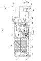
- Skeleton diagram of vehicle drive device The figure which shows the arrangement
- Speed diagram of transmission according to embodiment Partial sectional drawing of the vehicle drive device which concerns on embodiment Operation table of transmission according to embodiment Skeleton diagram of a part of a vehicle drive device according to another embodiment
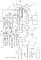
- the vehicle drive device 1 includes a transmission 4 that can change a gear ratio, a rotating electrical machine 3, and a power transmission path that transmits a driving force to an output member 91 that is drivingly connected to wheels 9. It is equipped with.
- this power transmission path is a power transmission path that connects the input shaft 90 that is drivingly connected to the internal combustion engine 2 and the output member 91.
- the vehicle drive device 1 further includes a differential gear device 7 and a case 6.
- the transmission 4 and the rotating electrical machine 3 are accommodated in the case 6.
- the case 6 accommodates a differential gear device 7 in addition to the transmission 4 and the rotating electrical machine 3.
- the input shaft 90 corresponds to an “input member”.
- the rotating electrical machine 3 is connected to the rotor 3b so as to rotate integrally, and is a power transmission path (a power transmission path for transmitting a driving force to the output member 91.
- the input shaft 90 and the output member 91 is provided with an output gear 3a that meshes with a gear provided in a power transmission path connecting to 91).
- the output gear 3 a meshes with the drive gear mechanism 10.
- the rotating electrical machine 3 is electrically connected to a power storage device (not shown) such as a battery or a capacitor, and is powered by power supplied from the power storage device, or the torque of the internal combustion engine 2 or the inertial force of the vehicle. The electric power generated by is supplied to the power storage device to be stored.
- the output gear 3a corresponds to an “output rotating member”.
- the rotating electrical machine 3 is arranged on a different axis from the first transmission mechanism 41 and the second transmission mechanism 42, and is further arranged on a different axis from the drive gear mechanism 10 in this embodiment. That is, the speed change mechanism (the first speed change mechanism 41 and the second speed change mechanism 42 in the present embodiment) is disposed on a separate axis from the rotating electrical machine 3. Specifically, the first transmission mechanism 41 is arranged on a separate axis from the rotating electrical machine 3, and the second transmission mechanism 42 is arranged on a separate axis from the rotating electrical machine 3 and the first transmission mechanism 41.
- the rotating electrical machine 3 is on the first side L1 from the drive gear mechanism 10 and overlaps the drive gear mechanism 10 or a member that rotates integrally with the drive gear mechanism 10 when viewed in the axial direction L.
- the members that rotate integrally with the drive gear mechanism 10 include members that are arranged coaxially with the drive gear mechanism 10 (here, on the third axis A3) and that always rotate integrally with the drive gear mechanism 10. It is.
- the fifth clutch C5 (specifically, the output side engaging member of the fifth clutch C5) corresponds to such a member.
- a member that rotates integrally with the drive gear mechanism 10 is a member that is disposed coaxially with the drive gear mechanism 10 and that rotates integrally with the drive gear mechanism 10 while being connected to the drive gear mechanism 10. Can also be included.
- the input-side engaging member and the input shaft 90 of the fifth clutch C5 that rotate integrally with the drive gear mechanism 10 in a directly connected state of the fifth clutch C5 correspond to such a member.
- the rotating electrical machine 3 is disposed so as to overlap the drive gear mechanism 10 when viewed in the axial direction L (see FIG. 2).
- the rotating electrical machine 3 is arranged so that the first transmission mechanism 41 and the arrangement area in the axial direction L overlap, and the second transmission mechanism 42 and the arrangement area in the axial direction L overlap.
- at least a part of the rotating electrical machine 3 is disposed so as to overlap each of the first transmission mechanism 41 and the second transmission mechanism 42 when viewed in the radial direction R (the radial direction of the rotating electrical machine 3).
- at least a part of a shift drum 53 described later is disposed so as to overlap each of the first transmission mechanism 41 and the second transmission mechanism 42 when viewed in the radial direction R (the radial direction of the rotating electrical machine 3).
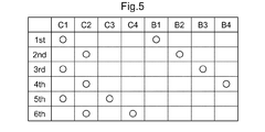
- the first speed change mechanism 41 forms an odd number of the plurality of forward speeds
- the second speed change mechanism 42 forms an even number of the plurality of forward speeds
- the odd-numbered gear is an odd-numbered gear when a plurality of forward gears are arranged in descending order of the gear ratio (in this embodiment, the first gear 1st, the third gear 3rd, and the fifth gear 5th).
- the even-numbered gear is an even-numbered gear when a plurality of forward gears are arranged in descending order of gear ratio (in this embodiment, second gear 2nd, fourth gear 4th, sixth gear 6th). It is. Therefore, as shown in FIG.
- the fifth clutch C5 is released when the electric travel mode is executed.
- the output gear 3a of the rotating electrical machine 3 is disposed closer to the input shaft 90 than the first clutch C1 and the second clutch C2 in the power transmission path between the input shaft 90 and the output member 91. It is connected to a member (specifically, drive gear mechanism 10). That is, the output gear 3a of the rotating electrical machine 3 is drivingly connected to the drive gear mechanism 10 without passing through the first clutch C1 and the second clutch C2. Therefore, by engaging the first clutch C1, the rotation of the rotating electrical machine 3 can be shifted by the first transmission mechanism 41 and transmitted to the output member 91, and by rotating the second clutch C2, the rotation can be performed.
- the first speed change mechanism 41 includes a first brake B1 that selectively fixes the third carrier CA3 to the case 6, and a third brake B3 that selectively fixes the first carrier CA1 and the third sun gear S3 to the case 6. And a third clutch C3 for selectively connecting the third carrier CA3 and the first carrier CA1 and the third sun gear S3.
- the second sleeve 82 and the fourth sleeve 84 are the sleeve 80 of the second meshing engagement device.
- the second sleeve 82 is a sleeve 80 common to the fourth brake B4 and the fourth clutch C4, and the fourth sleeve 84 is the sleeve 80 of the second brake B2.
- the state where the third brake B3 is engaged and the state where the third brake B3 is released are switched according to the position of the third sleeve 83 in the axial direction L. Further, the state in which the second brake B2 is engaged and the state in which the second brake B2 is released are switched according to the position of the fourth sleeve 84 in the axial direction L. As described above, the first sleeve 81 and the second sleeve 82 are switched in the position in the axial direction L between the three positions, and the third sleeve 83 and the fourth sleeve 84 are positioned in the two positions in the axial direction L. Can be switched between.
- the transmission driving device 5 includes a first shift fork 71 that transmits the operation of the cam mechanism to the first sleeve 81, a second shift fork 72 that transmits the operation of the cam mechanism to the second sleeve 82, There are provided four shift forks 70, a third shift fork 73 that transmits the operation of the cam mechanism to the third sleeve 83 and a fourth shift fork 74 that transmits the operation of the cam mechanism to the fourth sleeve 84.
- the shift fork 70 corresponds to the “transmission member”
- the first shift fork 71 and the third shift fork 73 correspond to the “first transmission member”
- the second shift fork 72 and the fourth shift fork 74 Corresponds to a “second transmission member”.
- the outer peripheral surface (cylindrical outer peripheral surface) of the shift drum 53 is referred to as a circumferential direction based on the rotational axis of the shift drum 53 (hereinafter referred to as “circumferential direction C”).
- a groove 50 (cam groove) is formed so as to extend.
- the groove part 50 is formed corresponding to each of the shift forks 70.
- Four groove portions 50 are formed on the outer peripheral surface of the shift drum 53.
- the shift fork 70 is connected to an engaging portion 60 that is slidably engaged with the groove portion 50 in the circumferential direction C.
- the engaging portion 60 is moved in the axial direction L in accordance with the shape of the groove portion 50 (meandering shape in which the position in the axial direction L changes according to the position in the circumferential direction C).
- the shift fork 70 connected to the engaging portion 60 is moved in the axial direction L.
- the shift fork 70 includes a fitting portion 63 (fork portion) that is slidably fitted into a groove formed on the outer peripheral surface of the sleeve 80, and the shift fork 70 is moved in the axial direction L.
- the sleeve 80 is moved in the axial direction L.
- the shift fork 70 transmits the operation of the engaging portion 60 accompanying the rotation of the shift drum 53 to the sleeve 80.
- a rotation position (set rotation position) corresponding to each gear position is set, and the shape of each groove portion 50 is set so that a corresponding gear position is formed at each set rotation position. Is set.
- the groove portion 50 for driving the sleeve 80 (81, 83) of the first meshing engagement device (B1, B3, C3) is defined as the first groove portion 51
- the second meshing engagement device (B2, B4). , C4), the groove 50 for driving the sleeve 80 (82, 84) is referred to as a second groove 52.
- the engaging portion 60 that is slidably engaged with the first groove portion 51 in the circumferential direction C is referred to as a first engaging portion 61, and is slidably engaged with the second groove portion 52 in the circumferential direction C.
- two first groove portions 51 and two second groove portions 52 are formed on the outer peripheral surface of the shift drum 53, and the two first engagement portions 61 and 2 are formed.
- Two second engaging portions 62 are engaged with the outer peripheral surface (groove portion 50) of the shift drum 53.
- the shift drive device 5 includes an actuator 54 that rotationally drives the shift drum 53 around the axial direction L.
- an electric motor can be used as the actuator 54.
- a drive gear 54 a provided on the output shaft of the actuator 54 and a driven gear 53 a provided on the shift drum 53 are connected via a reduction gear mechanism 55.
- the output rotation of 54 is decelerated by the reduction gear mechanism 55 and transmitted to the shift drum 53.
- the vehicle is provided with a control device that controls the vehicle drive device 1.
- the control device controls the drive of the actuator 54 and rotationally drives the shift drum 53.
- the shift stage to be formed is switched (shift change).
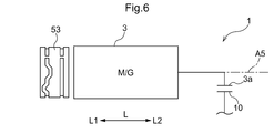
- the shift drum 53 is disposed so as to overlap the rotating electrical machine 3 when viewed in the axial direction L. That is, at least a part of the shift drum 53 is arranged at a position overlapping the rotating electrical machine 3 when viewed in the axial direction L. In the present embodiment, the entire shift drum 53 is disposed at a position overlapping the rotating electrical machine 3 when viewed in the axial direction L.
- the shift drum 53 is arrange
- the shift drum 53 is rotatable relative to the rotating electrical machine 3 between the rotating electrical machine 3 (rotor core) and the output gear 3a in the axial direction L (that is, does not hinder the rotation of the rotating electrical machine 3). Is in place).
- the shift drum 53 is disposed at a position at least partially overlapping with the rotating electrical machine 3 when viewed in the axial direction L, and is disposed between the rotor 3b (rotor core) and the output gear 3a in the axial direction L. Yes.
- the shift drum 53 is formed in a cylindrical shape extending in the axial direction L, and the rotor 3b and the output gear 3a of the rotating electrical machine 3 are formed in a space defined by the cylindrical inner peripheral surface of the shift drum 53. Is inserted in the axial direction L. In the example shown in FIG.
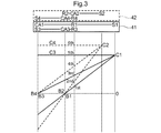
- the first axis A1 where the first transmission mechanism 41 is arranged and the second axis A2 where the second transmission mechanism 42 is arranged are viewed in the axial direction L.
- the first imaginary straight line X1 connecting the axis of the shift drum 53 (in this example, the fifth axis A5) and the axis of the output member 91 (in this example, the fourth axis A4) is disposed on the opposite side. Has been.
- the shaft center of the first meshing engagement device (B1, B3, C3) and the second meshing engagement device (B2) can be arranged at a position where the distance is approximately the same (distance in the axial direction L view) from each of the shaft centers of B4 and C4).
- the sleeves 80 of the first meshing engagement device and the second meshing engagement device arranged on different shafts by the common shift drum 53 with a relatively simple configuration.
- the first axis A1 and the second axis A2 are arranged with respect to the position in the direction parallel to the first imaginary straight line X1.
- 5 axes A5) are located on the same side with respect to each other, and are further located on the same side with respect to the axis of the drive gear mechanism 10 (in this example, the third axis A3).
- either the rotating electrical machine 3 or the shift drum 53 is parallel to the first virtual line X1 and on the same side as the first axis A1 with respect to the first virtual line X1.
- a virtual straight line in contact with the outer periphery of the larger diameter is defined as a second virtual straight line X2, which is parallel to the first virtual straight line X1 and the second axis A2 with respect to the first virtual straight line X1.
- a virtual straight line that is in contact with the outer circumference of the rotating electrical machine 3 or the shift drum 53 (in this embodiment, the rotating electrical machine 3) on the same side as the third virtual straight line X3 is orthogonal to the first virtual straight line X1.
- the shift drum 53 is disposed so as to overlap the rotating electrical machine 3 when viewed in the axial direction L, and the rotating electrical machine 3 is generally a relatively large-diameter device as shown in FIG. Therefore, it is possible to ensure a large diameter of the shift drum 53 while suppressing an increase in the size of the vehicle drive device 1 in a direction orthogonal to the axial direction L.
- the first shift fork 71 and the second shift fork 72 switch the position of the corresponding sleeve 80 in the axial direction L between three positions
- the third shift fork 73 and the fourth shift fork 74 are The position of the corresponding sleeve 80 in the axial direction L is switched between the two positions. Therefore, the first groove 51 that the first engagement portion 61 of the first shift fork 71 engages and the second groove 52 that the second engagement portion 62 of the second shift fork 72 engages are the engagement portion 60.
- the first groove portion 51 engaged with the first engagement portion 61 of the third shift fork 73 and the second engagement of the fourth shift fork 74 are formed so as to switch the position in the axial direction L between the three positions.
- the 2nd groove part 52 with which the joint part 62 engages is formed in the shape which switches the position of the axial direction L of the engaging part 60 between two positions. And in this embodiment, the 1st groove part 51 and the 2nd groove part 52 in which the number of the positions of the axial direction L where the engaging part 60 is switched are mutually the same are provided along with the circumferential direction C.
- the shift drum 53 is disposed between the rotor 3b and the output gear 3a in the axial direction L. Since the output gear 3a is disposed on the second side L2 with respect to the rotor 3b, the shift drum 53 is disposed on the second side L2 with respect to the rotor 3b and on the first side L1 with respect to the output gear 3a. ing.
- the arrangement configuration of the shift drum 53 in the vehicle drive device 1 of the present embodiment will be described with reference to FIG.
- connection part 92c is a connection part by spline engagement.
- the spline teeth formed on the inner peripheral surface of one of the first shaft portion 92a and the second shaft portion 92b (the first shaft portion 92a in the example shown in FIG. 4), the first shaft portion 92a and the second shaft portion 92b
- the spline teeth formed on the outer peripheral surface of the other of the two shaft portions 92b (the second shaft portion 92b in the example shown in FIG. 4) are engaged with each other at the connecting portion 92c, whereby the first shaft portion 92a and the second shaft portion.
- the rotation sensor 93 that detects the rotation of the rotating electrical machine 3 is arranged on the opposite side of the connecting portion 92c with respect to the rotor 3b in the axial direction L (that is, the first side L1 with respect to the rotor 3b).
- the rotation sensor 93 is a sensor for detecting the rotational position of the rotor 3b with respect to the stator 3c, and a resolver is used as the rotation sensor 93 in the example shown in FIG.
- the vehicle drive device 1 includes a first rotor bearing 98a, a second rotor bearing 98b, a third rotor bearing 98c, and a fourth rotor bearing 98d as bearings for rotatably supporting the rotor shaft 92. .
- These bearings (98a, 98b, 98c, 98d) are radial bearings that can receive a load in the radial direction R, and in this embodiment, ball bearings are used.
- the first rotor bearing 98a is disposed on the second side L2 with respect to the rotor 3b, and supports the first shaft portion 92a from the outer side in the radial direction R so as to be rotatable with respect to the case 6.
- the second rotor bearing 98b is disposed on the first side L1 with respect to the output gear 3a, and supports the second shaft portion 92b from the outside in the radial direction R so as to be rotatable with respect to the case 6.
- the third rotor bearing 98c is disposed on the first side L1 with respect to the rotor 3b, and supports the first shaft portion 92a from the outer side in the radial direction R so as to be rotatable with respect to the case 6.
- the fourth rotor bearing 98d is disposed on the second side L2 with respect to the output gear 3a, and supports the second shaft portion 92b from the outside in the radial direction R so as to be rotatable with respect to the case 6.
- the 1st rotor bearing 98a is arrange
- the first shaft portion 92a is rotatably supported by the first rotor bearing 98a
- the second shaft portion 92b is rotatably supported by the second rotor bearing 98b.
- the first rotor bearing 98a and the second rotor bearing 98b correspond to “rotor bearings”.
- the cylindrical support member 56 includes a main body portion 56a and a support portion 56c.
- the main body portion 56 a is a portion (cylindrical portion extending in the axial direction L) disposed in a space surrounded by the cylindrical inner peripheral surface of the shift drum 53, and is radial with respect to the inner peripheral surface of the shift drum 53. It has a cylindrical outer peripheral surface facing (in the radial direction with respect to the axis of the shift drum 53, which is the same as the radial direction R in this embodiment).
- the support portion 56c is a portion (a portion to be fixed) that supports the main body portion 56a with respect to a fixing member (the case 6 itself or a member fixed to the case 6).
- the main body portion 56a and the fixing member are provided so as to be connected to each other.
- the support portion 56c is formed so as to extend along the radial direction R (here, parallel to the radial direction R).
- the main body portion 56a is disposed on the second side L2 with respect to the support portion 56c.
- a wall portion provided in the case 6 (specifically, a wall portion provided between the rotor 3b and the output gear 3a in the axial direction L to support the rotor shaft 92), It is used as the support part 56c.
- a rotor bearing (a first rotor bearing 98a and a second rotor bearing 98b) that rotatably supports the rotor shaft 92 is disposed between the inner peripheral surface of the cylindrical support member 56 and the outer peripheral surface of the rotor shaft 92. ing. Specifically, the first rotor bearing 98a is disposed between the inner peripheral surface of the cylindrical support member 56 and the outer peripheral surface of the first shaft portion 92a. That is, the first rotor bearing 98a and the first rotor bearing 98a on the inner peripheral surface of the cylindrical support member 56 overlap with the portion where the arrangement region in the axial direction L overlaps (the portion overlapping the first rotor bearing 98a in the radial direction R view).
- a cylindrical first bearing support surface having a diameter corresponding to the outer diameter is formed.
- the first bearing support surface is formed at the inner end portion in the radial direction R of the support portion 56 c.
- the second rotor bearing 98b is disposed between the inner peripheral surface of the cylindrical support member 56 and the outer peripheral surface of the second shaft portion 92b. That is, the second rotor bearing 98b and the second rotor bearing 98b on the inner peripheral surface of the cylindrical support member 56 overlap with the portion where the arrangement region in the axial direction L overlaps (the portion that overlaps the second rotor bearing 98b when viewed in the radial direction R).
- a cylindrical second bearing support surface having a diameter corresponding to the outer diameter is formed.
- the portion on the first side L1 of the second bearing support surface is formed at the inner end portion in the radial direction R of the main body portion 56a, and the second side L2 of the second bearing support surface. Is an end portion on the inner side in the radial direction R in a portion (a portion where a regulating portion 56b described later is formed on the outer side in the radial direction R) located on the second side L2 with respect to the main body portion 56a in the cylindrical support member 56. Is formed.
- both the support of the rotor shaft 92 and the support of the shift drum 53 are performed by using the inner peripheral surface and the outer peripheral surface of one cylindrical support member 56.
- the cylindrical support member 56 includes a restricting portion 56 b that protrudes radially outward on both sides in the axial direction L with respect to the shift drum 53 and restricts the movement range of the shift drum 53 in the axial direction L. ing.
- the restricting portion 56b is in the radial direction with respect to the outer peripheral surface of the main body portion 56a on each of both sides in the axial direction L with respect to the main body portion 56a (in the radial direction with reference to the axis of the shift drum 53) In this case, the projections are provided so as to protrude outward in the radial direction R).
- a regulating surface is formed that contacts the end surface of the shift drum 53 in the axial direction L and regulates the movement of the shift drum 53 in the axial direction L.
- the restricting portion 56b on the first side L1 is formed by a portion located on the outer side in the radial direction R with respect to the outer peripheral surface of the main body portion 56a in the support portion 56c.
- the cylindrical support member 56 has a portion formed integrally with the main body portion 56 a so as to be positioned on the second side L ⁇ b> 2 with respect to the main body portion 56 a, and the diameter at the portion.
- the outer side portion in the direction R forms a restricting portion 56b on the second side L2. That is, in the example shown in FIG. 4, the restricting portion 56b on the first side L1 is configured by a member different from the main body portion 56a, and the restricting portion 56b on the second side L2 is formed integrally with the main body portion 56a. Yes.
- the shift drum 53 has one of the first rotor bearing 98a and the second rotor bearing 98b (specifically, the second rotor bearing 98b) and the radial direction R (the radial direction of the shift drum 53).
- the configuration arranged so as to overlap with each other has been described as an example.
- the present invention is not limited to such a configuration, and the shift drum 53 is disposed so as to overlap the first rotor bearing 98a in the radial direction R.
- the shift drum 53 includes the first rotor bearing 98a and the second rotor.
- the portion including the end portion of the first side L1 of the shift drum 53 is the same as the portion including the end portion of the second rotor L2 of the first rotor bearing 98a in the radial direction R (the radial direction of the shift drum 53).
- the portion including the end portion on the second side L2 of the shift drum 53 overlaps the portion including the end portion on the first side L1 of the second rotor bearing 98b in the radial direction R.
- the main body 56a is disposed on the first side L1 with respect to the support 56c, and the main body 56a and the support 56c are integrally formed. Is formed.
- the support part 56c is comprised by the member different from the case 6, and the support part 56c is being fixed with the fastening member (this example fastening bolt) with respect to the case 6 (periphery wall part).
- the restricting portion 56b on the first side L1 is configured by a member different from the main body portion 56a.
- the cylindrical support member 56 includes a cylindrical member that is externally fitted to an end portion of the first side L1 of the member that constitutes the main body portion 56a.
- a restricting portion 56b is formed.
- This cylindrical member is also used as an attachment portion of the rotation sensor 93.
- the sensor stator of the rotation sensor 93 is attached to the cylindrical member from the first side L1.
- the configuration in which the cylindrical support member 56 includes the restricting portion 56b has been described as an example.
- the present invention is not limited to such a configuration, and when the movement range of the shift drum 53 in the axial direction L is restricted by another member or another mechanism, the cylindrical support member 56 is disposed on both sides in the axial direction L. It can also be set as the structure which is not provided with at least one of the control parts 56b.
- the configuration in which the shift drum 53 is disposed coaxially with the rotating electrical machine 3 has been described as an example.
- the present invention is not limited to such a configuration, and the shift drum 53 is arranged on a separate axis from the rotating electrical machine 3 at a position at least partially overlapping the rotating electrical machine 3 when viewed in the axial direction L. You can also.
- the shift drum 53 is arranged on a different axis (hereinafter referred to as “sixth axis”) from the rotating electrical machine 3, the inner peripheral surface of one cylindrical support member 56 is similar to the above embodiment.
- the inner peripheral surface of the cylindrical support member 56 (at least the portion that supports the rotor bearing from the radially outer side).
- the peripheral surface is formed in a cylindrical shape having the fifth axis A5 as an axis
- the outer peripheral surface of the cylindrical support member 56 (main body portion 56a) is formed in a cylindrical shape having the sixth axis as an axis. That is, the fifth axis A5 that is the axis of the inner peripheral surface of the cylindrical support member 56 is arranged eccentrically with respect to the sixth axis that is the axis of the outer peripheral surface of the cylindrical support member 56.
- the rotor shaft 92 does not penetrate the shift drum 53 in the axial direction L, that is, the rotor shaft 92 as viewed in the axial direction L. It is also possible to adopt a configuration in which the arrangement area of the shift drum 53 and the arrangement area of the shift drum 53 do not overlap. In the above embodiment, the configuration in which the diameter of the outer peripheral surface of the shift drum 53 is smaller than the diameter of the outer peripheral surface of the rotating electrical machine 3 has been described as an example.
- the diameter of the outer peripheral surface of the shift drum 53 is not limited to such a configuration, and the diameter of the outer peripheral surface of the shift drum 53 is the same as the diameter of the outer peripheral surface of the rotary electric machine 3. 3 may be larger than the diameter of the outer peripheral surface 3.
- the rotor shaft 92 includes the first shaft portion 92a to which the rotor 3b is fixed, and the second shaft portion 92b to which the output gear 3a is fixed.
- the biaxial portion 92b has been described as an example of a configuration in which the two shaft portions 92b are formed of separate members and are connected via the connecting portion 92c.
- the configuration is not limited to such a configuration, and a portion corresponding to the first shaft portion 92a and a portion corresponding to the second shaft portion 92b in the rotor shaft 92 may be integrally formed. .
- the shift drum 53 having a length in the axial direction L shorter than the distance in the axial direction L between the end surface of the second side L2 of the rotor 3b and the end surface of the first side L1 of the output gear 3a is used.
- the shift drum 53 can be disposed between the rotor 3b and the output gear 3a in the axial direction L as in the above embodiment.
- the configuration in which the first groove portion 51 and the second groove portion 52 are provided side by side in the circumferential direction C has been described as an example.
- the configuration is not limited to such a configuration, and the first groove portion 51 and the second groove portion 52 may be provided at different positions in the axial direction L.
- a configuration in which the plurality of first groove portions 51 are provided side by side in the circumferential direction C, a configuration in which the plurality of second groove portions 52 are provided in the circumferential direction C, and all the groove portions 50 formed in the shift drum 53 are in the circumferential direction. It can also be set as the structure provided along with C, etc.
- the second virtual line X2, the third virtual line X3, the fourth virtual line X4, and the fifth virtual line The configuration arranged in the region surrounded by the straight line X5 has been described as an example. However, without being limited to such a configuration, one or both of the first axis A1 and the second axis A2 may be the second virtual line X2, the third virtual line X3, the fourth virtual line X4, and the fifth virtual line. It can also be set as the structure arrange
- the first shaft A1 where the first transmission mechanism 41 is disposed and the second shaft A2 where the second transmission mechanism 42 is disposed are viewed in the axial direction L and the shift drum 53 Opposite to each other across a first imaginary straight line X1 connecting the axis (in the example of the above embodiment, the fifth axis A5) and the axis of the output member 91 (in the example of the above embodiment, the fourth axis A4).
- the arrangement to be arranged has been described as an example.
- the present invention is not limited to such a configuration, and the first axis A1 and the second axis A2 are arranged on the same side with respect to the first virtual straight line X1 when viewed in the axial direction L. You can also.
- the transmission 4 includes the first meshing engagement device (B1, B3, C3) and the second meshing engagement device (B2, B4, C4), and the transmission driving device.
- 5 is a shift fork 70 (71, 73) that transmits the operation of the cam mechanism according to the rotation of the shift drum 53 to the sleeve 80 (81, 83) of the first meshing engagement device, and the rotation of the shift drum 53.
- the configuration including the shift fork 70 (72, 74) that transmits the operation of the corresponding cam mechanism to the sleeve 80 (82, 84) of the second meshing engagement device has been described as an example.
- the present invention is not limited to such a configuration, and the speed change drive device 5 is configured to include a second shift drum different from the shift drum 53, and the speed change drive device 5 has a cam corresponding to the rotation of the shift drum 53.
- the shift fork 70 transmitting the operation of the mechanism to the sleeve 80 of the second meshing engagement device
- the operation of the cam mechanism according to the rotation of the second shift drum is applied to the sleeve 80 of the second meshing engagement device. It can also be set as the structure provided with the shift fork transmitted.
- the configuration in which the output gear 3a of the rotating electrical machine 3 is engaged with the drive gear mechanism 10 has been described as an example.
- the present invention is not limited to such a configuration, and the output gear 3a of the rotating electrical machine 3 and the drive gear mechanism 10 can be driven and connected via another transmission member (such as an idler gear).
- the output gear 3a of the rotating electrical machine 3 is meshed with the first driven gear 21 or the second driven gear 22, that is, the output gear 3a of the rotating electrical machine 3 is the first driven gear 21 or the second driven gear.
- a configuration may be adopted in which the drive gear mechanism 10 is drivingly connected via the gear 22.
- the output gear 3a of the rotating electrical machine 3 is disposed on the input shaft 90 side of the speed change mechanism (the first speed change mechanism 41 and the second speed change mechanism 42) in the power transmission path connecting the input shaft 90 and the output member 91. It is configured not to be a member (in the above embodiment, the drive gear mechanism 10) but to be connected to a member (for example, the output member 91) disposed on the output member 91 side of the speed change mechanism in the power transmission path. You can also. In such a case, unlike the above embodiment, the output gear 3a of the rotating electrical machine 3 is drivingly connected to the drive gear mechanism 10 via at least one of the first clutch C1 and the second clutch C2. Become.
- the configuration in which the rotating electrical machine 3 is disposed on a different shaft from the drive gear mechanism 10 has been described as an example.
- the configuration is not limited to such a configuration, and the rotary electric machine 3 may be arranged coaxially with the drive gear mechanism 10.
- the output gear 3a of the rotating electrical machine 3 may be connected so as to rotate integrally with the drive gear mechanism 10.
- the output rotating member of the rotating electrical machine 3 is not the output gear 3a but a shaft member that rotates integrally with the rotor 3b of the rotating electrical machine 3. You can also.
- the drive gear mechanism 10 is configured by the common drive gear that meshes with both the first driven gear 21 and the second driven gear 22
- the drive gear mechanism 10 includes a first drive gear that meshes with the first driven gear 21 and a second drive gear that meshes with the second driven gear 22. It can also be configured.
- the first speed change mechanism 41 changes the speed of the rotation of the first drive gear included in the drive gear mechanism 10 and transmits it to the output member 91
- the second speed change mechanism 42 is the second drive gear included in the drive gear mechanism 10. Is rotated and transmitted to the output member 91.
- the first clutch C1 is replaced with a power transmission path between the drive gear mechanism 10 and the first transmission mechanism 41.
- the input shaft 90 is provided in the power transmission path between the first drive gear and the second clutch C2 is replaced with the power transmission path between the drive gear mechanism 10 and the second speed change mechanism 42.
- a second power transmission path between the first drive gear and the second drive gear a first clutch C1 connects or disconnects the input shaft 90 and the first drive gear
- the second clutch C2 connects or disconnects the input shaft 90 and the second drive gear.
- the output gear 3a of the rotating electrical machine 3 is set to one of the first drive gear and the second drive gear. It can be set as a meshing structure.
- the configuration in which the vehicle drive device 1 includes the fifth clutch C5 has been described as an example.
- the present invention is not limited to such a configuration, and the vehicle drive device 1 may not include the fifth clutch C5, and the input shaft 90 and the drive gear mechanism 10 may always rotate integrally.
- the power transmission path in which the transmission 4 and the rotating electrical machine 3 are provided is a power transmission path that connects the input shaft 90 that is drivingly connected to the internal combustion engine 2 and the output member 91. Described as an example.
- the present invention is not limited to such a configuration, and a configuration in which the output torque of the internal combustion engine 2 (input shaft 90) is not transmitted to a power transmission path in which the transmission 4 and the rotating electrical machine 3 are provided (for example, a vehicle drive device). 1 may be configured not to include the input shaft 90 and the fifth clutch C5 shown in FIG. That is, the vehicle drive device 1 can be a drive device for an electric vehicle (electric vehicle) instead of a drive device for a hybrid vehicle.
- the configurations of the first transmission mechanism 41 and the second transmission mechanism 42 shown in the above embodiment are merely examples, and specific configurations of the first transmission mechanism 41 and the second transmission mechanism 42 (the planetary gear mechanism used)
- the type single pinion type, double pinion type, Ravigneaux type, etc.
- the number of planetary gear mechanisms used the arrangement of the engaging devices for each rotating element, etc. can be changed as appropriate.
- the transmission 4 provided in the vehicle drive device 1 has two transmission mechanisms (the first transmission mechanism 41 and the second transmission mechanism 42) and two for switching between the two transmission mechanisms.
- the configuration provided with the engagement devices has been described as an example.
- the technology according to the present disclosure can be applied to the vehicle drive device 1 including the transmission 4 having another configuration without being limited to such a configuration.
- the other configurations of the transmission 4 include all configurations including at least one meshing engagement device.
- the transmission 4 includes a parallel-shaft gear-type transmission mechanism or a transmission mechanism.
- a transmission in which all the planetary gear mechanisms are coaxially arranged can be exemplified. Specifically, as an example, in the configuration of FIG.
- the transmission 4 includes the drive gear mechanism 10, the first driven gear 21, the first transmission mechanism 41, and the first output gear 31.
- the transmission 4 can be configured not to include the second driven gear 22, the second transmission mechanism 42, the second output gear 32, the first clutch C1, and the second clutch C2. That is, the transmission 4 is configured to include only one of the first transmission mechanism 41 and the second transmission mechanism 42 in the above embodiment (that is, the transmission 4 includes only one transmission mechanism). Can do.
- the rotating electrical machine 3 is an inner rotor type rotating electrical machine
- the rotating electrical machine 3 may be an outer rotor type rotating electrical machine, or the rotating electrical machine 3 may be an axial gap type rotating electrical machine instead of a radial gap type.
- the transmission (4) includes at least one meshing engagement device (B1 to B4, C3, C4) and the meshing engagement device (B1 to B4, C3).
- the shift drum (53) and the rotating electrical machine (3) As a result, the region where only the shift drum (53) is disposed in the axial direction (L) can be reduced. Thereby, it becomes possible to arrange
- the transmission (4) is a driving gear to which at least one of the rotational driving force of the rotating electrical machine (3) and the rotational driving force of the input member (90) connected to the internal combustion engine (2) is transmitted. It is preferable to provide the mechanism (10).
- the rotational driving force of the driving force source (2, 3) can be appropriately input to the transmission (4).
- the transmission changes the rotation of the drive gear mechanism (10) and transmits the rotation to the output member (91). It is preferable that the first transmission mechanism (41) and the second transmission mechanism (42), which are two transmission mechanisms (41, 42), are provided.
- the degree of freedom in setting the transmission ratio of the transmission (4) and the degree of freedom in the layout of the transmission (4) are compared with the case where the transmission (4) includes only one transmission mechanism. , It will be easier to secure both sides.
- the transmission (4) includes the first transmission mechanism (41) and the second transmission mechanism (42) as described above
- the first transmission mechanism (41) is connected to the rotating electrical machine (3).
- the second transmission mechanism (42) is preferably disposed on a separate shaft from the rotating electrical machine (3) and the first transmission mechanism (41).
- the transmission mechanism (41, 42) and the rotating electrical machine (3) can be easily disposed close to the axial direction (L) and at the same time in the radial direction (R) of the rotating electrical machine (3).
- the rotating electrical machine (3) can be arranged so as to overlap the transmission mechanism (41, 42) as seen, and the entire apparatus can be reduced in the axial direction (L).
- the first speed change mechanism (41) is arranged on a separate shaft from the rotating electrical machine (3), and the second speed change mechanism (42) is arranged on the rotating electrical machine (3) and the first speed change mechanism ( 41), in which the rotating electrical machine (3) includes at least a part of the first speed change mechanism (41) and the first transmission mechanism (41) when viewed in the radial direction (R) of the rotating electrical machine (3). It is preferable that the second transmission mechanism (42) is disposed so as to overlap each other.
- the rotating electrical machine (3) is seen in the radial direction (R) of the rotating electrical machine (3), and each of the first transmission mechanism (41) and the second transmission mechanism (42).
- the shift drum (53) is arranged coaxially with the rotating electrical machine (3), and at least a part of the shift drum (53) has a diameter of the rotating electrical machine (3). It is preferable that the first transmission mechanism (41) and the second transmission mechanism (42) are disposed so as to overlap each other when viewed in the direction (R).
- the shift drum (53) is arranged so as not to overlap with either the first transmission mechanism (41) or the second transmission mechanism (42) when viewed in the radial direction (R). It is possible to reduce the size of the entire apparatus in the axial direction (L).
- the first speed change mechanism (41) is arranged on a separate shaft from the rotating electrical machine (3), and the second speed change mechanism (42) is arranged on the rotating electrical machine (3) and the first speed change mechanism ( 41),
- the first transmission mechanism (41) includes a first meshing engagement device (B1, B3, C3) that is the meshing engagement device
- the two speed change mechanism (42) includes a second meshing engagement device (B2, B4, C4)
- the speed change drive device (5) is the shift drum (53) of the cam mechanism formed by the shift drum (53). ) Is transmitted to the engaging members (81, 83) of the first meshing engagement devices (B1, B3, C3).
- a second transmission member (72, 74) which is a transmission member (70) for transmitting the operation to the engagement member (82, 84) of the second meshing engagement device (B2, B4, C4). It is preferable that
- the engagement members (80) of the first meshing engagement devices (B1, B3, C3) and the second meshing engagement devices (B2, B4, C4) disposed on different axes from each other. ) Can be driven by a common shift drum (53). Therefore, the shift drum for driving the engagement member (80) of the first meshing engagement device (B1, B3, C3) and the engagement member of the second meshing engagement device (B2, B4, C4) Compared with the case where a shift drum for driving (80) is provided separately, the entire apparatus can be reduced in size, and the number of parts and cost can be reduced.
- the first speed change mechanism (41) The rotation of the drive gear mechanism (10) is changed at different speed ratios depending on the state of the engagement members (81, 83) of the first meshing engagement device (B1, B3, C3), and the output member ( 91), the second transmission mechanism (42) is disposed on a second shaft (A2) different from the first shaft (A1) on which the first transmission mechanism (41) is disposed, and The output member is configured to change the rotation of the drive gear mechanism (10) at a different gear ratio according to the state of the engagement member (82, 84) of the second meshing engagement device (B2, B4, C4).
- the first axis (A1) and the second axis (A2) When viewed in the direction (L), they are preferably arranged on opposite sides across a first virtual straight line (X1) connecting the axis of the shift drum (53) and the axis of the output member (91). It is.
- the first meshing engagement device (B1, B1) is positioned at the same distance from the first shaft (A1) and the second shaft (A2) when viewed in the axial direction (L).
- B3, C3) and the second meshing engagement device (B2, B4, C4) from the center of each of the shift drums (53) at the same distance in the axial direction (L).
- An axis can be arranged.
- the combined member (80) can be driven by the common shift drum (53).
- the first axis (A1) and the second axis (A2) are arranged on opposite sides of the first virtual straight line (X1) when viewed in the axial direction (L).
- the rotary electric machine on the same side as the first axis (A1) parallel to the first virtual line (X1) and on the same side as the first axis (A1) with respect to the axial direction (L).
- a virtual straight line in contact with the outer periphery of the larger one of the diameters of the shift drum (53) is defined as a second virtual straight line (X2), which is parallel to the first virtual straight line (X1) and the first virtual line
- a virtual straight line in contact with the outer circumference of the rotating electrical machine (3) or the shift drum (53) having the larger diameter on the same side as the second axis (A2) with respect to the straight line (X1) is defined as a third virtual straight line ( X3) and perpendicular to the first imaginary straight line (X1) and the shift drum 53) is a fourth virtual straight line (X4), and a virtual straight line orthogonal to the first virtual straight line (X1) and passing through the axial center of the output member (91) is a fifth virtual straight line ( X5), when the first axis (A1) and the second axis (A2) are viewed in the axial direction (L), the second virtual line (X2), the third virtual line (X3), It is preferable that they are arranged in a region
- the separation distance can be set to a similar distance. Therefore, the axial centers of the rotating electrical machine (3) and the shift drum (53) are arranged at positions that are approximately the same distance from the first axis (A1) and the second axis (A2) when viewed in the axial direction (L). It becomes easy to do.
- the first transmission member (71, 73) A first engagement that is slidably engaged in the circumferential direction (C) with respect to a first groove (51) formed on the outer peripheral surface of the shift drum (53) so as to extend in the circumferential direction (C).
- the engagement member of the first meshing engagement device (B1, B3, C3) is connected to the portion (61), and the operation of the first engagement portion (61) accompanying the rotation of the shift drum (53)
- the second transmission member (72, 74) is formed on the outer peripheral surface of the shift drum (53) so as to extend in the circumferential direction (C).
- the second engaging portion (62) that is slidably engaged in the circumferential direction (C).
- the operation of the second engagement portion (62) accompanying the rotation of the shift drum (53) is transmitted to the engagement members (82, 84) of the second meshing engagement devices (B2, B4, C4).
- the first groove portion (51) and the second groove portion (52) are provided side by side in the circumferential direction (C).
- the first groove portion (51) and the second groove portion (52) in the axial direction (L) of the shift drum (53) are compared with the case where the first groove portion (51) and the second groove portion (52) are provided at different positions in the axial direction (L).
- the length can be kept short.
- the rotating electrical machine (3) is generally a device having a relatively large diameter, and the shift drum (53) is arranged so as to overlap with the rotating electrical machine (3) as viewed in the axial direction (L) as described above.
- the diameter of the shift drum (53) is reduced between the first groove portion (51) and the second groove portion (52) in the circumferential direction (C) while suppressing the enlargement of the entire apparatus in the direction orthogonal to the axial direction (L). It is possible to secure a large extent to be provided side by side.
- At least a part of the transmission member (70) is arranged so as to overlap the drive gear mechanism (10) when viewed in the axial direction (L).
- the transmission member (70) overlaps the drive gear mechanism (10) when viewed in the axial direction (L), the region where only the transmission member (70) is disposed when viewed in the axial direction (L) is reduced. Can be reduced. Therefore, in addition to the shift drum (53), the transmission member (70) driven by the shift drum (53) can be arranged while suppressing an increase in the size of the entire apparatus in the direction orthogonal to the axial direction (L).
- the transmission (4) includes the drive gear mechanism (10) and the A first clutch (C1) that connects or disconnects the first transmission mechanism (41), and a second clutch (C2) that connects or disconnects the drive gear mechanism (10) and the second transmission mechanism (42).
- the output rotating member (3a) of the rotating electrical machine (3) is drivingly connected to the driving gear mechanism (10) without passing through the first clutch (C1) and the second clutch (C2). It is preferable that
- the shift drum (53) can be arranged while suppressing an increase in the size of the entire apparatus in the direction orthogonal to the axial direction (L).
- the transmission (4) shifts the rotation of the drive gear mechanism (10) and the output member (91). It is preferable that the transmission mechanism is disposed on a separate shaft from the rotating electrical machine (2).
- the transmission mechanism and the rotating electrical machine (3) it is easy to dispose the transmission mechanism and the rotating electrical machine (3) close to the axial direction (L), and the transmission mechanism and the rotating electrical machine (3) are viewed in the radial direction (R).
- the rotating electrical machines (3) can be arranged so as to overlap each other, and the entire apparatus can be reduced in the axial direction (L).
- the speed change mechanism is disposed on a different axis from the rotating electrical machine (2)
- at least a part of the rotating electrical machine (3) is in the radial direction (R) of the rotating electrical machine (3). It is preferable that it is arranged so as to overlap with the speed change mechanism.
- the transmission (4) includes the drive gear mechanism (10) as described above, at least a part of the shift drum (53) is seen in the axial direction (L) and the drive gear mechanism (10 It is preferable that they are arranged so as to overlap with each other.
- the shift drum (53) is disposed coaxially with the rotating electrical machine (3).
- the support structure for rotatably supporting the shift drum (53) is compared with the case where the shift drum (53) is arranged on a different axis from the rotary electric machine (3). It becomes easy to share a part with the structure, and accordingly, it is easy to reduce the size and cost of the vehicle drive device (1).
- the diameter of the outer peripheral surface of the shift drum (53) is smaller than the diameter of the outer peripheral surface of the rotating electrical machine (3).
- the rotating electrical machine (3) is connected to the rotor (3b) and the rotor (3b) so as to rotate integrally therewith and is provided in the power transmission path.
- an output gear (3a) meshing with the gear, and the shift drum (53) is disposed between the rotor (3b) and the output gear (3a) in the axial direction (L). It is preferable.
- the shift drum (53) is disposed at a position overlapping the rotating electrical machine (3) when viewed in the axial direction (L), and in such an arrangement, the rotating electrical machine (3) and the shift drum are disposed. Since (53) is aligned in the axial direction (L), the apparatus is easily increased in size in the axial direction (L).
- the rotor (3b) and the output gear (3a) as rotating bodies included in the rotating electrical machine (3) must be supported by a rotation support structure such as a bearing or a support member of the bearing, and such rotation
- the support structure is often arranged side by side with the rotor (3b) in the axial direction (L).
- the shift drum (53) is disposed between the rotor (3b) and the output gear (3a) in the axial direction (L), the axial direction necessary for the arrangement of these rotation support structures is provided.
- the shift drum (53) can be arranged using the space (L). Therefore, the enlargement of the apparatus in the axial direction (L) can be limited.
- the enlargement as a whole of the vehicle drive device (1) provided with the rotary electric machine (3) and the shift drum (53) can be suppressed.
- the shift drum (53) is arranged coaxially with the rotating electrical machine (3), and a rotor shaft (92) that connects the rotor (3b) and the output gear (3a) includes the shift drum. It is preferable that (53) is penetrated in the axial direction (L).
- the rotating electrical machine (3) rotates integrally with the rotor (3b) and the rotor (3b).
- a rotor shaft (92) disposed between the output gear (3a) and connecting the rotor (3b) and the output gear (3a) passes through the shift drum (53) in the axial direction (L). It is preferable to do so.
- the shift drum (53) is disposed between the rotor (3b) and the output gear (3a) in the axial direction (L), and the rotor (3b) and the output gear (3a) are connected to each other. Since the connecting rotor shaft (92) passes through the shift drum (53) in the axial direction (L), the axial direction required for the arrangement of the rotation support structure of the rotor (3b) and the output gear (3a)
- the shift drum (53) can be arranged using the space (L). Therefore, the enlargement of the axial direction (L) of the apparatus due to the rotating electric machine (3) and the shift drum (53) being arranged in the axial direction (L) can be limited. As a result, the overall size of the vehicle drive device (1) including the rotating electrical machine (3) and the shift drum (53) can be suppressed.
- the shift drum (53) is disposed coaxially with the rotating electrical machine (3), and the rotor shaft (92) penetrates the shift drum (53) in the axial direction (L).
- a cylindrical support member (56) is disposed on the radially inner side of the shift drum (53) through the shift drum (53) in the axial direction (L), and the cylindrical support member (56).
- the cylindrical support member (56) is disposed on the radially inner side of the shift drum (53) as described above, the cylindrical support member (56) is It is preferable that a restricting portion (56b) that protrudes radially outward on both sides in the axial direction (L) and restricts the movement range of the shift drum (53) in the axial direction (L) is suitable.
- the movement of the shift drum (53) in the axial direction (L) can also be regulated by the cylindrical support member (56). Therefore, compared with the case where such movement restriction is performed by a member different from the cylindrical support member (56), it is easier to reduce the size and cost of the vehicle drive device (1).
- the rotating electrical machine (3) As a rotor shaft (92) for connecting the rotor (3b) and the output gear (3a), a first shaft portion (92a) to which the rotor (3b) is fixed and the output gear (3a) are fixed.
- a second shaft portion (92b), and the first shaft portion (92a) and the second shaft portion (92b) are formed of separate members and connected via a connecting portion (92c).
- the first shaft portion (92a) is rotatably supported by a first rotor bearing (98a), and the second shaft portion (92b) is rotatably supported by a second rotor bearing (98b).
- the shift drum (53) is configured such that the first rotor shaft (98a) and at least one of the second rotor bearing (98b), it is preferable that the shift drum (53) is arranged so as to overlap when viewed in the radial direction of the (R).
- the first rotor bearing (98a) and the second shaft for supporting them are provided.
- the shift drum (53) can be arranged using the space in the axial direction (L) necessary for the arrangement of at least one of the rotor bearings (98b). Therefore, according to this configuration, it is easy to reduce the size of the vehicle drive device (1) in the axial direction (L).
- the first shaft portion (92a) is rotatably supported by the first rotor bearing (98a), and the second shaft portion (92b) is rotatably supported by the second rotor bearing (98b).
- the shift drum (53) overlaps both the first rotor bearing (98a) and the second rotor bearing (98b) in the radial direction (R) of the shift drum (53). It is preferable that they are arranged in the above.
- the first rotor bearing (98a) and the second The shift drum (53) can be arranged by utilizing the space in the axial direction (L) necessary for the arrangement of the two rotor bearings (98b). Therefore, according to this configuration, it is easier to reduce the size of the vehicle drive device (1) in the axial direction (L).
- the vehicle drive device only needs to exhibit at least one of the effects described above.
Abstract
変速機(4)は、少なくとも1つの噛み合い式係合装置と、当該噛み合い式係合装置の係合部材を駆動する変速駆動装置とを備える。変速駆動装置は、シフトドラム(53)を備える。シフトドラム(53)の少なくとも一部が、軸方向に見て回転電機(3)と重なる位置に配置される。
Description
本発明は、車輪に駆動連結される出力部材に駆動力を伝達する動力伝達経路に、変速比を変更可能な変速機と、回転電機と、が設けられた車両用駆動装置に関する。
上記のような車両用駆動装置の一例として、米国特許出願公開第2015/0176682号明細書(特許文献1)には、デュアルクラッチ式の変速機と回転電機とが設けられた車両用駆動装置が記載されている。特許文献1の図1等に示されるように、このデュアルクラッチ式の変速機は、第2クラッチ(24)及び第3クラッチ(26)を有するデュアルクラッチ装置(22)と、第1変速部(20)及び第2変速部(32)を有する平行軸歯車装置(28)と、を備えている。そして、特許文献1の段落0017には、平行軸歯車装置の変速段を、シフトドラムによって切り替えることが好ましいとの記載がある。
ところで、シフトドラムの外周面にはシフトフォークを軸方向に移動させるためのカム溝が周方向に沿って形成されるため、シフトドラムは径方向にある程度の大きさを有する形状に形成される。そのため、シフトドラムの配置位置によっては、軸方向に直交する方向における車両用駆動装置の寸法が、車両への搭載性を低下させる程度に大きくなるおそれがある。しかしながら、特許文献1には、車両への搭載性を考慮したシフトドラムの配置構成について記載されていない。
そこで、軸方向に直交する方向における装置全体の大型化を抑制しつつ、シフトドラムを配置することが可能な車両用駆動装置の実現が望まれる。
上記に鑑みた、車輪に駆動連結される出力部材に駆動力を伝達する動力伝達経路に、変速比を変更可能な変速機と、回転電機と、が設けられた車両用駆動装置の特徴構成は、前記変速機は、少なくとも1つの噛み合い式係合装置と、当該噛み合い式係合装置の係合部材を駆動する変速駆動装置と、を備え、前記変速駆動装置は、シフトドラムを備え、前記シフトドラムの少なくとも一部が、軸方向に見て前記回転電機と重なる位置に配置されている点にある。
上記の特徴構成によれば、シフトドラムの少なくとも一部が軸方向に見て回転電機と重なる位置に配置されるため、シフトドラムと回転電機とが軸方向に見て重なる分、軸方向に見てシフトドラムのみが配置される領域を低減することができる。これにより、軸方向に直交する方向における装置全体の大型化を抑制しつつシフトドラムを配置することが可能となる。なお、回転電機は一般に比較的大径の装置とされるため、シフトドラムをこのような回転電機と軸方向に見て重なるように配置することで、軸方向に見てシフトドラムのみが配置される領域の低減を図りやすい。
車両用駆動装置の実施形態について、図面を参照して説明する。ここでは、本開示に係る技術を、2つの変速機構及び当該2つの変速機構を切り替えるための2つの係合装置を有する変速機を備える車両用駆動装置に適用した場合を例として説明する。なお、以下の説明における各部材についての方向は、それらが車両用駆動装置に組み付けられた状態での方向を表す。また、各部材についての方向や位置等に関する用語は、製造上許容され得る誤差による差異を有する状態を含む概念である。
本明細書では、「駆動連結」とは、2つの回転要素が駆動力を伝達可能に連結された状態を意味する。この概念には、2つの回転要素が一体回転するように連結された状態や、2つの回転要素が1つ以上の伝動部材を介して駆動力を伝達可能に連結された状態が含まれる。このような伝動部材には、回転を同速で又は変速して伝達する各種の部材(軸、歯車機構、ベルト、チェーン等)が含まれ、回転及び駆動力を選択的に伝達する係合装置(摩擦係合装置や噛み合い式係合装置等)が含まれてもよい。但し、遊星歯車機構の各回転要素について「駆動連結」という場合には、当該遊星歯車機構が備える3つの回転要素に関して互いに他の回転要素を介することなく駆動連結されている状態を指すものとする。
また、本明細書では、「回転電機」は、モータ(電動機)、ジェネレータ(発電機)、及び必要に応じてモータ及びジェネレータの双方の機能を果たすモータ・ジェネレータのいずれをも含む概念として用いている。また、本明細書では、2つの部材の配置に関して、「ある方向に見て重なる」とは、その視線方向に平行な仮想直線を当該仮想直線に直交する各方向に移動させた場合に、当該仮想直線が2つの部材の双方に交わる領域が少なくとも一部に存在することを意味する。例えば、「径方向に見て重なる」とは、当該仮想直線が2つの部材の双方に交わる領域が、周方向の少なくとも一部の領域に存在することを意味する。
図1に示すように、本実施形態では、車両用駆動装置1は、車輪9の駆動力源として内燃機関2及び回転電機3の双方を備える車両(ハイブリッド車両)を駆動するための駆動装置(ハイブリッド車両用駆動装置)である。車両用駆動装置1は、内燃機関2及び回転電機3の少なくとも一方のトルクを車輪9に伝達させて車両を走行させる。本実施形態の車両用駆動装置1は、FF(Front Engine Front Drive)車両用の駆動装置として構成されている。なお、図1では、内燃機関2をENG(Engine)と表記し、回転電機3をM/G(Motor/Generator)と表記している。
図1に示すように、車両用駆動装置1は、車輪9に駆動連結される出力部材91に駆動力を伝達する動力伝達経路に、変速比を変更可能な変速機4と、回転電機3と、を備えている。本実施形態では、この動力伝達経路は、内燃機関2に駆動連結される入力軸90と、出力部材91とを結ぶ動力伝達経路である。本実施形態では、車両用駆動装置1は、更に、差動歯車装置7と、ケース6と、を備えている。図2に示すように、ケース6には、変速機4及び回転電機3が収容される。本実施形態では、ケース6には、変速機4及び回転電機3に加えて、差動歯車装置7が収容されている。本実施形態では、入力軸90が「入力部材」に相当する。
内燃機関2は、機関内部における燃料の燃焼により駆動されて動力を取り出す原動機(例えば、ガソリンエンジン、ディーゼルエンジン等)である。入力軸90は、内燃機関2の出力軸(クランクシャフト等)に駆動連結される。入力軸90は、内燃機関2の出力軸と一体回転するように連結され、或いは、ダンパ等の他の部材を介して内燃機関2の出力軸に駆動連結される。
差動歯車装置7は、変速機4の側から差動入力ギヤ7aに入力される回転及びトルクを、左右2つの出力軸8(すなわち、左右2つの車輪9)に分配して伝達する。ここで、出力軸8は、差動歯車装置7と車輪9とを連結する軸(ドライブシャフト)である。入力軸90の回転駆動力は、変速機4(後述する駆動ギヤ機構10)に入力され、変速機4により変速された入力軸90の回転駆動力が、変速機4から出力部材91に出力される。そして、変速機4の側から出力部材91に入力された回転駆動力は、差動歯車装置7に入力される。本実施形態では、差動入力ギヤ7aが出力部材91として用いられており(出力部材91として機能しており)、変速機4により変速された入力軸90の回転駆動力は、差動歯車装置7(差動入力ギヤ7a)に直接入力される。
回転電機3は、車輪9の駆動力源として用いられる。変速機4は、入力軸90の回転駆動力が伝達される駆動ギヤ機構10と、駆動ギヤ機構10の回転を変速して出力部材91に伝達する変速機構(本実施形態では、第1変速機構41及び第2変速機構42)とを備えており、回転電機3の出力ギヤ3aは、駆動ギヤ機構10に駆動連結されている。よって、駆動ギヤ機構10には、回転電機3の回転駆動力及び入力軸90の回転駆動力の少なくとも一方が伝達される。本実施形態では、出力ギヤ3aは外歯のギヤである。図4に示すように、回転電機3は、ケース6に固定されるステータ3cと、ステータ3cに対して回転自在に支持されるロータ3bと、を備えている。本実施形態では、回転電機3はインナロータ型の回転電機であり、ロータ3bは、ステータ3cよりも径方向Rの内側であって径方向Rに見てステータ3cと重なる位置に配置されている。ここで、「径方向R」は、回転電機3が配置される第5軸A5を基準とする径方向である。回転電機3のロータ3bには、出力ギヤ3aが一体回転するように連結されている。すなわち、回転電機3は、ロータ3bと一体回転するように連結されていると共に動力伝達経路(出力部材91に駆動力を伝達する動力伝達経路であり、本実施形態では、入力軸90と出力部材91とを結ぶ動力伝達経路)に設けられたギヤに噛み合う出力ギヤ3aを備えている。後述するように、本実施形態では、出力ギヤ3aは駆動ギヤ機構10に噛み合っている。回転電機3は、バッテリやキャパシタ等の蓄電装置(図示せず)と電気的に接続されており、蓄電装置から電力の供給を受けて力行し、或いは、内燃機関2のトルクや車両の慣性力により発電した電力を蓄電装置に供給して蓄電させる。本実施形態では、出力ギヤ3aが「出力回転部材」に相当する。
変速機4は、少なくとも1つの噛み合い式係合装置と、当該噛み合い式係合装置のスリーブ(ドグスリーブ)を駆動する変速駆動装置5と、を備えている。本実施形態では、変速機4は、複数の噛み合い式係合装置を備えている。具体的には、図1に示すように、変速機4は、第1ブレーキB1、第2ブレーキB2、第3ブレーキB3、第4ブレーキB4、第3クラッチC3、及び第4クラッチC4を備えており、これらのブレーキ及びクラッチ(B1~B4,C3,C4)はいずれも噛み合い式係合装置とされている。これらの噛み合い式係合装置の係合の状態は、スリーブ80の状態(具体的には、軸方向Lの位置)に応じて切り替えられる。詳細は後述するが、変速駆動装置5は、スリーブ80を駆動してスリーブ80の軸方向Lの位置を切り替えるように構成されている。なお、軸方向Lは、後述するシフトドラム53の回転軸(仮想軸)に平行な方向である。以下では、軸方向Lの一方側を第1側L1とし、軸方向Lの他方側を第2側L2とする。後述する各軸(第1軸A1、第2軸A2、第3軸A3、第4軸A4、及び第5軸A5)は、軸方向Lに平行な軸(仮想軸)である。詳細は省略するが、各噛み合い式係合装置には、係合の対象となる2つの回転部材の回転を同期させるシンクロ機構(同期機構)が設けられている。本実施形態では、スリーブ80が「係合部材」に相当する。
本実施形態では、変速機4は、第1変速機構41と第2変速機構42とを備えている。第1変速機構41は第1噛み合い式係合装置(B1,B3,C3)を備え、第2変速機構42は第2噛み合い式係合装置(B2,B4,C4)を備えている。第1変速機構41は、第1噛み合い式係合装置(ここでは、第1ブレーキB1、第3ブレーキB3、及び第3クラッチC3)のスリーブ80(ここでは、第1スリーブ81及び第3スリーブ83)の状態に応じて異なる変速比で駆動ギヤ機構10の回転を変速して出力部材91に伝達する変速機構である。変速機4は、駆動ギヤ機構10の回転を第1変速機構41に入力するためのギヤとして、駆動ギヤ機構10に噛み合う第1被駆動ギヤ21を備えると共に、第1変速機構41により変速された駆動ギヤ機構10の回転を出力部材91に出力するためのギヤとして、出力部材91に噛み合う第1出力ギヤ31を備えている。すなわち、第1変速機構41は、第1被駆動ギヤ21の回転を変速して第1出力ギヤ31に伝達する。
また、第2変速機構42は、第2噛み合い式係合装置(ここでは、第2ブレーキB2、第4ブレーキB4、及び第4クラッチC4)のスリーブ80(ここでは、第2スリーブ82及び第4スリーブ84)の状態に応じて異なる変速比で駆動ギヤ機構10の回転を変速して出力部材91に伝達する変速機構である。変速機4は、駆動ギヤ機構10の回転を第2変速機構42に入力するためのギヤとして、駆動ギヤ機構10に噛み合う第2被駆動ギヤ22を備えると共に、第2変速機構42により変速された駆動ギヤ機構10の回転を出力部材91に出力するためのギヤとして、出力部材91に噛み合う第2出力ギヤ32を備えている。すなわち、第2変速機構42は、第2被駆動ギヤ22の回転を変速して第2出力ギヤ32に伝達する。
図2に示すように、第1被駆動ギヤ21と第2被駆動ギヤ22とは、駆動ギヤ機構10を基準とする周方向(第3軸A3を基準とする周方向)の互いに異なる位置で、駆動ギヤ機構10に噛み合っている。本実施形態では、回転電機3の出力ギヤ3aも駆動ギヤ機構10に噛み合っており、回転電機3の出力ギヤ3aは、第1被駆動ギヤ21及び第2被駆動ギヤ22とは周方向(第3軸A3を基準とする周方向)の異なる位置で、駆動ギヤ機構10に噛み合っている。また、第1出力ギヤ31と第2出力ギヤ32とは、出力部材91を基準とする周方向(第4軸A4を基準とする周方向)の互いに異なる位置で、出力部材91に噛み合っている。
変速機4は、入力軸90と第1変速機構41とを連結又は連結解除する第1クラッチC1と、入力軸90と第2変速機構42とを連結又は連結解除する第2クラッチC2と、を備えている。第1クラッチC1及び第2クラッチC2のうちの第1クラッチC1のみを係合することで、入力軸90の回転を変速するための変速機構が第1変速機構41に切り替わり、第1クラッチC1及び第2クラッチC2のうちの第2クラッチC2のみを係合することで、入力軸90の回転を変速するための変速機構が第2変速機構42に切り替わる。このように、第1クラッチC1及び第2クラッチC2は、入力軸90の回転を変速して出力部材91に伝達する変速機構を、第1変速機構41と第2変速機構42との間で切り替えるためのクラッチである。
本実施形態では、駆動ギヤ機構10は、第1被駆動ギヤ21及び第2被駆動ギヤ22の双方に噛み合う共通駆動ギヤにより構成されている。そのため、第1クラッチC1及び第2クラッチC2は、駆動ギヤ機構10と変速機構(41,42)との間の動力伝達経路に設けられる。具体的には、第1クラッチC1は、第1被駆動ギヤ21と第1変速機構41(本実施形態では、後述する第1サンギヤS1)との間の動力伝達経路に設けられ、第1被駆動ギヤ21と第1変速機構41とを連結又は連結解除する。また、第2クラッチC2は、第2被駆動ギヤ22と第2変速機構42(本実施形態では、後述する第2サンギヤS2)との間の動力伝達経路に設けられ、第2被駆動ギヤ22と第2変速機構42とを連結又は連結解除する。すなわち、本実施形態では、第1クラッチC1は、駆動ギヤ機構10と第1変速機構41とを連結又は連結解除するクラッチであり、第2クラッチC2は、駆動ギヤ機構10と第2変速機構42とを連結又は連結解除するクラッチである。
駆動ギヤ機構10は、入力軸90に駆動連結されている。本実施形態では、図1に示すように、車両用駆動装置1は、入力軸90と駆動ギヤ機構10とを連結又は連結解除する第5クラッチC5を備えている。回転電機3の出力ギヤ3aは、第5クラッチC5を介することなく駆動ギヤ機構10に駆動連結されている。第5クラッチC5は、内燃機関2のトルクのみを車輪9に伝達させて車両を走行させる内燃機関走行モードの実行時や、内燃機関2及び回転電機3の双方のトルクを車輪9に伝達させて車両を走行させるハイブリッド走行モードの実行時に、係合した状態に制御され、回転電機3のトルクのみを車輪9に伝達させて車両を走行させる電動走行モードの実行時に、解放した状態に制御される。
図1及び図2に示すように、第1変速機構41、第2変速機構42、及び駆動ギヤ機構10は、互いに平行な3つの軸(第1軸A1、第2軸A2、及び第3軸A3)に分かれて配置されている。すなわち、第2変速機構42は、第1変速機構41が配置される第1軸A1とは別の第2軸A2に配置されている。このため、第2変速機構42に設けられる第2噛み合い式係合装置(ここでは、第2ブレーキB2、第4ブレーキB4、及び第4クラッチC4)は、第1変速機構41に設けられる第1噛み合い式係合装置(ここでは、第1ブレーキB1、第3ブレーキB3、及び第3クラッチC3)とは別軸(すなわち、第1噛み合い式係合装置が配置される第1軸A1とは異なる第2軸A2)に配置されている。また、第2変速機構42は、第1変速機構41と軸方向Lの配置領域が重なるように配置されている。すなわち、第2変速機構42は、第1変速機構41の径方向に見て第1変速機構41と重なる位置に配置されている。なお、図2は、車両用駆動装置1の各部品の軸方向L視での配置関係を示している。具体的には、各ギヤについては基準ピッチ円を一点鎖線で示し、回転電機3については外形(図4に示すように回転電機3がインナロータ型である場合には、ステータ3c(ステータコア)の円筒状部分の外周面)を一点鎖線で示し、後述するシフトドラム53については外形を実線で示し、後述するアクチュエータ54については外形を一点鎖線で示している。
本実施形態では、第1変速機構41、第2変速機構42、駆動ギヤ機構10、差動歯車装置7、及び回転電機3が、互いに平行な5つの軸(第1軸A1、第2軸A2、第3軸A3、第4軸A4、及び第5軸A5)に分かれて配置されている。具体的には、第1変速機構41が第1軸A1上に配置され、第2変速機構42が第2軸A2上に配置され、駆動ギヤ機構10が第3軸A3上に配置され、差動歯車装置7が第4軸A4上に配置され、回転電機3が第5軸A5上に配置されている。
このように、回転電機3は、第1変速機構41や第2変速機構42とは異なる軸上に配置されており、本実施形態では更に駆動ギヤ機構10とも異なる軸上に配置されている。すなわち、変速機構(本実施形態では、第1変速機構41及び第2変速機構42)は、回転電機3とは別軸に配置されている。具体的には、第1変速機構41が、回転電機3とは別軸に配置され、第2変速機構42が、回転電機3及び第1変速機構41とは別軸に配置されている。また、本実施形態では、回転電機3は、駆動ギヤ機構10よりも第1側L1であって、軸方向Lに見て駆動ギヤ機構10又は駆動ギヤ機構10と一体回転する部材と重なるように配置されている。駆動ギヤ機構10と一体回転する部材には、駆動ギヤ機構10と同軸に(ここでは、第3軸A3上に)配置される部材であって、駆動ギヤ機構10と常に一体回転する部材が含まれる。本実施形態では、第5クラッチC5(具体的には、第5クラッチC5の出力側係合部材)が、このような部材に該当する。駆動ギヤ機構10と一体回転する部材に、駆動ギヤ機構10と同軸に配置される部材であって、駆動ギヤ機構10との連結状態が維持された状態で駆動ギヤ機構10と一体回転する部材を含めることもできる。本実施形態では、第5クラッチC5の直結状態で駆動ギヤ機構10と一体回転する第5クラッチC5の入力側係合部材や入力軸90が、このような部材に該当する。本実施形態では、回転電機3は、軸方向Lに見て駆動ギヤ機構10と重なるように配置されている(図2参照)。また、本実施形態では、回転電機3は、軸方向Lに見て駆動ギヤ機構10と一体回転する部材と重なるように配置されており、具体的には、軸方向Lに見て第5クラッチC5及び入力軸90と重なるように配置されている。このように、本実施形態では、回転電機3は、軸方向Lに見て駆動ギヤ機構10及び駆動ギヤ機構10と一体回転する部材の双方と重なるように配置されている。図2に示すように、本実施形態では、回転電機3は、軸方向Lに見て駆動ギヤ機構10の軸心(第3軸A3)と重なるように配置されている。また、本実施形態では、回転電機3は、第1変速機構41と軸方向Lの配置領域が重なるように配置されていると共に、第2変速機構42と軸方向Lの配置領域が重なるように配置されている。すなわち、本実施形態では、回転電機3の少なくとも一部が、径方向R(回転電機3の径方向)に見て第1変速機構41及び第2変速機構42のそれぞれと重なるように配置されている。また、本実施形態では、後述するシフトドラム53の少なくとも一部が、径方向R(回転電機3の径方向)に見て第1変速機構41及び第2変速機構42のそれぞれと重なるように配置されている。
以下、本実施形態に係る第1変速機構41及び第2変速機構42の具体的構成について説明する。変速機4は、変速比の異なる複数の変速段を形成可能な有段の変速機(ここでは、自動変速機)である。本実施形態では、図5に示すように、変速機4は、変速比の異なる6つの前進用変速段(第1段1st、第2段2nd、第3段3rd、第4段4th、第5段5th、第6段6th)を形成可能に構成されている。これらの前進用変速段は、第1段から第6段に向かって(すなわち、高速段側に向かって)変速比が段階的に小さくなる。ここで、「変速比」は、出力部材91の回転速度に対する駆動ギヤ機構10の回転速度の比である。
本実施形態では、第1変速機構41は、複数の前進用変速段のうちの奇数段を形成し、第2変速機構42は、複数の前進用変速段のうちの偶数段を形成する。ここで、奇数段とは、複数の前進用変速段を変速比が大きい順に並べた場合の奇数番目の変速段(本実施形態では、第1段1st、第3段3rd、第5段5th)であり、偶数段とは、複数の前進用変速段を変速比が大きい順に並べた場合の偶数番目の変速段(本実施形態では、第2段2nd、第4段4th、第6段6th)である。よって、図5に示すように、変速機4が奇数段を形成する場合には、第1クラッチC1が係合されると共に第2クラッチC2が解放されることで、駆動ギヤ機構10の回転が、第1変速機構41に入力される。また、変速機4が偶数段を形成する場合には、第1クラッチC1が解放されると共に第2クラッチC2が係合されることで、駆動ギヤ機構10の回転が、第2変速機構42に入力される。なお、図5では、「○」は、当該係合装置(クラッチ又はブレーキ)が係合されることを示し、「無印」は、当該係合装置が解放されることを示している。
上述したように、電動走行モードの実行時には、第5クラッチC5が解放される。本実施形態では、回転電機3の出力ギヤ3aが、入力軸90と出力部材91との間の動力伝達経路における、第1クラッチC1及び第2クラッチC2よりも入力軸90の側に配置される部材(具体的には、駆動ギヤ機構10)に連結されている。すなわち、回転電機3の出力ギヤ3aは、第1クラッチC1及び第2クラッチC2を介することなく駆動ギヤ機構10に駆動連結されている。そのため、第1クラッチC1を係合することで、回転電機3の回転を第1変速機構41によって変速して出力部材91に伝達させることができ、第2クラッチC2を係合することで、回転電機3の回転を第2変速機構42によって変速して出力部材91に伝達させることができる。すなわち、電動走行モードを、第1変速機構41により形成される奇数段と第2変速機構42により形成される偶数段との双方で実現することが可能となっている。また、第1変速機構41により形成される奇数段と第2変速機構42により形成される偶数段との双方で、ハイブリッド走行モードを実現すること(すなわち、回転電機3にアシストトルクを発生させること)や、回転電機3による発電を行うこと(すなわち、回転電機3に回生トルクを発生させること)が可能となっている。
本実施形態では、第1変速機構41は、2つの遊星歯車機構を備えている。そして、当該2つの遊星歯車機構のそれぞれが有する3つの回転要素のうち、2つずつが互いに一体回転するように連結されることで、全体として4つの回転要素を備えた遊星歯車装置が形成されている。具体的には、図1に示すように、第1変速機構41は、第1サンギヤS1、第1キャリヤCA1、及び第1リングギヤR1を有するダブルピニオン型の遊星歯車機構と、第3サンギヤS3、第3キャリヤCA3、及び第3リングギヤR3を有するシングルピニオン型の遊星歯車機構とを備えている。そして、第1リングギヤR1と第3リングギヤR3とが一体回転するように連結されると共に、第1キャリヤCA1と第3サンギヤS3とが一体回転するように連結されている。また、第1サンギヤS1が、第1クラッチC1を介して第1被駆動ギヤ21に連結され、第1リングギヤR1及び第3リングギヤR3が、第1出力ギヤ31と一体回転するように連結されている。そして、第1変速機構41は、第3キャリヤCA3をケース6に選択的に固定する第1ブレーキB1と、第1キャリヤCA1及び第3サンギヤS3をケース6に選択的に固定する第3ブレーキB3と、第3キャリヤCA3と第1キャリヤCA1及び第3サンギヤS3とを選択的に連結する第3クラッチC3と、を備えている。
また、本実施形態では、第2変速機構42は、2つの遊星歯車機構を備えている。そして、当該2つの遊星歯車機構のそれぞれが有する3つの回転要素のうち、2つずつが互いに一体回転するように連結されることで、全体として4つの回転要素を備えた遊星歯車装置が形成されている。具体的には、図1に示すように、第2変速機構42は、第2サンギヤS2、第2キャリヤCA2、及び第2リングギヤR2を有するシングルピニオン型の遊星歯車機構と、第4サンギヤS4、第4キャリヤCA4、及び第4リングギヤR4を有するシングルピニオン型の遊星歯車機構とを備えている。そして、第2リングギヤR2と第4キャリヤCA4とが一体回転するように連結されると共に、第2キャリヤCA2と第4リングギヤR4とが一体回転するように連結されている。また、第2サンギヤS2が、第2クラッチC2を介して第2被駆動ギヤ22に連結され、第2キャリヤCA2及び第4リングギヤR4が、第2出力ギヤ32と一体回転するように連結されている。そして、第2変速機構42は、第2リングギヤR2及び第4キャリヤCA4をケース6に選択的に固定する第2ブレーキB2と、第4サンギヤS4をケース6に選択的に固定する第4ブレーキB4と、第2リングギヤR2及び第4キャリヤCA4と第4サンギヤS4とを選択的に連結する第4クラッチC4と、を備えている。
図3は、上記のように構成される第1変速機構41及び第2変速機構42の速度線図(共線図)である。図3において、縦軸は、図3の上部に示す各回転要素(第1変速機構41の4つの回転要素及び第2変速機構42の4つの回転要素)の回転速度に対応し、「0」は回転速度がゼロであることを示し、上側が正、下側が負となっている。そして、図5に示すように各係合装置(C1,C2,C3,C4,B1,B2,B3,B4)の係合の状態が制御されることで、各前進用変速段が形成される。
図3では、第1変速機構41及び第2変速機構42のそれぞれの速度線図を、駆動ギヤ機構10の回転速度が互いに等しくなるように重ねて示している。図2に示すように、本実施形態では、第2被駆動ギヤ22が第1被駆動ギヤ21よりも小径に形成されている。よって、第1被駆動ギヤ21の回転速度に対する駆動ギヤ機構10の回転速度の比よりも、第2被駆動ギヤ22の回転速度に対する駆動ギヤ機構10の回転速度の比が小さい値となる。この結果、図3に示すように、第2クラッチC2が係合された状態での第2サンギヤS2の回転速度(第2被駆動ギヤ22の回転速度)が、第1クラッチC1が係合された状態での第1サンギヤS1の回転速度(第1被駆動ギヤ21の回転速度)よりも高くなっている。
図1に示すように、本実施形態では、車両用駆動装置1は、第1スリーブ81、第2スリーブ82、第3スリーブ83、及び第4スリーブ84の4つのスリーブ80を備えている。第1スリーブ81及び第3スリーブ83は、第1噛み合い式係合装置のスリーブ80である。具体的には、第1スリーブ81は、第1ブレーキB1及び第3クラッチC3に共通のスリーブ80であり、第3スリーブ83は、第3ブレーキB3のスリーブ80である。また、第2スリーブ82及び第4スリーブ84は、第2噛み合い式係合装置のスリーブ80である。具体的には、第2スリーブ82は、第4ブレーキB4及び第4クラッチC4に共通のスリーブ80であり、第4スリーブ84は、第2ブレーキB2のスリーブ80である。
そして、第1スリーブ81の軸方向Lの位置に応じて、第1ブレーキB1及び第3クラッチC3のうちの第3クラッチC3のみが係合した状態と、第1ブレーキB1及び第3クラッチC3のうちの第1ブレーキB1のみが係合した状態と、第1ブレーキB1及び第3クラッチC3の双方が解放された状態と、が切り替えられる。また、第2スリーブ82の軸方向Lの位置に応じて、第4ブレーキB4及び第4クラッチC4のうちの第4クラッチC4のみが係合した状態と、第4ブレーキB4及び第4クラッチC4のうちの第4ブレーキB4のみが係合した状態と、第4ブレーキB4及び第4クラッチC4の双方が解放された状態と、が切り替えられる。また、第3スリーブ83の軸方向Lの位置に応じて、第3ブレーキB3が係合した状態と、第3ブレーキB3が解放した状態と、が切り替えられる。また、第4スリーブ84の軸方向Lの位置に応じて、第2ブレーキB2が係合した状態と、第2ブレーキB2が解放した状態と、が切り替えられる。このように、第1スリーブ81及び第2スリーブ82は、軸方向Lの位置が3つの位置の間で切り替えられ、第3スリーブ83及び第4スリーブ84は、軸方向Lの位置が2つの位置の間で切り替えられる。
次に、変速駆動装置5の構成について説明する。図1に示すように、変速駆動装置5は、シフトドラム53とシフトフォーク70とを備えている。シフトドラム53は、カム機構を構成する部材である。シフトドラム53は、軸方向L周りに回転可能に支持されている。シフトドラム53は、軸受(本実施形態では、後述するドラム支持軸受99、図4参照)によってケース6に対して回転可能に支持されている。また、シフトフォーク70は、シフトドラム53の回転に応じたカム機構の動作をスリーブ80に伝達する部材である。本実施形態では、変速駆動装置5は、上記カム機構の動作を第1スリーブ81に伝達する第1シフトフォーク71、上記カム機構の動作を第2スリーブ82に伝達する第2シフトフォーク72、上記カム機構の動作を第3スリーブ83に伝達する第3シフトフォーク73、及び上記カム機構の動作を第4スリーブ84に伝達する第4シフトフォーク74の、4つのシフトフォーク70を備えている。本実施形態では、シフトフォーク70が「伝達部材」に相当し、第1シフトフォーク71及び第3シフトフォーク73が「第1伝達部材」に相当し、第2シフトフォーク72及び第4シフトフォーク74が「第2伝達部材」に相当する。
シフトドラム53は円筒カム機構を構成しており、シフトフォーク70によってスリーブ80に伝達される円筒カム機構の動作によって、スリーブ80が軸方向Lに移動するように駆動される。具体的には、シフトフォーク70は、スリーブ80の回転を許容する状態でスリーブ80と一体的に軸方向Lに移動するように構成されている。なお、シフトフォーク70は、軸方向Lに移動可能にケース6に支持されている。そして、変速駆動装置5は、シフトドラム53を回転駆動してシフトフォーク70を軸方向Lに移動させることで、スリーブ80を軸方向Lに移動させる。
具体的には、図1に示すように、シフトドラム53の外周面(円筒状の外周面)には、シフトドラム53の回転軸心を基準とする周方向(以下、「周方向C」という。図2参照。)に延びるように溝部50(カム溝)が形成されている。溝部50は、シフトフォーク70のそれぞれに対応して形成されている。具体的には、第1シフトフォーク71に対応する溝部50、第2シフトフォーク72に対応する溝部50、第3シフトフォーク73に対応する溝部50、及び第4シフトフォーク74に対応する溝部50の4つの溝部50が、シフトドラム53の外周面に形成されている。そして、シフトフォーク70は、溝部50に対して周方向Cに摺動自在に係合する係合部60に連結されている。
よって、シフトドラム53の回転に伴い係合部60が溝部50の形状(周方向Cの位置に応じて軸方向Lの位置が変化する蛇行形状)に合わせて軸方向Lに移動されることで、当該係合部60に連結されたシフトフォーク70が軸方向Lに移動される。そして、シフトフォーク70は、スリーブ80の外周面に形成された溝部に摺動自在に嵌合する嵌合部63(フォーク部)を備えており、シフトフォーク70が軸方向Lに移動されることで、スリーブ80が軸方向Lに移動される。このように、シフトフォーク70は、シフトドラム53の回転に伴う係合部60の動作をスリーブ80に伝達する。なお、シフトドラム53の回転位置として、各変速段に対応する回転位置(設定回転位置)が設定されており、各設定回転位置において対応する変速段が形成されるように、各溝部50の形状が設定されている。
ここで、第1噛み合い式係合装置(B1,B3,C3)のスリーブ80(81,83)を駆動するための溝部50を第1溝部51とし、第2噛み合い式係合装置(B2,B4,C4)のスリーブ80(82,84)を駆動するための溝部50を第2溝部52とする。そして、第1溝部51に対して周方向Cに摺動自在に係合する係合部60を第1係合部61とし、第2溝部52に対して周方向Cに摺動自在に係合する係合部60を第2係合部62とすると、本実施形態では、第1シフトフォーク71及び第3シフトフォーク73は、第1係合部61に連結され、シフトドラム53の回転に伴う第1係合部61の動作を第1噛み合い式係合装置(B1,B3,C3)のスリーブ80(81,83)に伝達する。また、本実施形態では、第2シフトフォーク72及び第4シフトフォーク74は、第2係合部62に連結され、シフトドラム53の回転に伴う第2係合部62の動作を第2噛み合い式係合装置(B2,B4,C4)のスリーブ80(82,84)に伝達する。このように、本実施形態では、シフトドラム53の外周面には、2本の第1溝部51と2本の第2溝部52とが形成されており、2つの第1係合部61と2つの第2係合部62とがシフトドラム53の外周面(溝部50)に係合している。
変速駆動装置5は、シフトドラム53を軸方向L周りに回転駆動するアクチュエータ54を備えている。アクチュエータ54として、例えば電動モータを用いることができる。本実施形態では、図1に示すように、アクチュエータ54の出力軸に設けられる駆動ギヤ54aとシフトドラム53に設けられる被駆動ギヤ53aとが、減速ギヤ機構55を介して連結されており、アクチュエータ54の出力回転が減速ギヤ機構55により減速されてシフトドラム53に伝達されるように構成されている。車両には、車両用駆動装置1を制御対象とする制御装置が設けられており、この制御装置は、アクチュエータ54の駆動を制御してシフトドラム53を回転駆動することで、変速機4にて形成される変速段の切替(シフトチェンジ)を行う。具体的には、シフトドラム53が切替後の変速段(目標変速段)を形成する回転位置まで回転駆動されることで、変速段が切り替えられる。なお、シフトチェンジのタイミングは、例えば、変速マップに従って決定され、或いは、運転者による操作(シフトレバー操作等)に応じて決定される。
次に、本開示の要部である変速駆動装置5の配置構成について説明する。図2に示すように、シフトドラム53は、軸方向Lに見て回転電機3と重なるように配置される。すなわち、シフトドラム53の少なくとも一部は、軸方向Lに見て回転電機3と重なる位置に配置される。本実施形態では、シフトドラム53の全体が、軸方向Lに見て回転電機3と重なる位置に配置されている。このようにシフトドラム53を回転電機3と軸方向Lに見て重なるように配置することで、軸方向Lに直交する方向における車両用駆動装置1の大型化を抑制しつつシフトドラム53を配置することが可能となっている。
図1及び図2に示すように、本実施形態では、シフトドラム53は、回転電機3と同軸上に(すなわち、第5軸A5上に)配置されている。そして、本実施形態では、シフトドラム53の外周面の径は、回転電機3の外周面の径(例えば、ステータコアの外周面の径)よりも小さい。この結果、上述したように、シフトドラム53の全体が、軸方向Lに見て回転電機3と重なる位置に配置されている。
図1に示すように、本実施形態では、回転電機3、第1変速機構41、及び第2変速機構42の全てが、駆動ギヤ機構10よりも第1側L1に配置されている。そして、本実施形態では、シフトドラム53は、回転電機3(ロータコア)よりも第2側L2に配置されている。具体的には、シフトドラム53は、軸方向Lにおける回転電機3(ロータコア)と出力ギヤ3aとの間に、回転電機3に対して相対回転自在に(すなわち、回転電機3の回転を阻害しない状態で)配置されている。すなわち、シフトドラム53は、軸方向Lに見て回転電機3と少なくとも一部で重なる位置に配置されていると共に、軸方向Lにおけるロータ3b(ロータコア)と出力ギヤ3aとの間に配置されている。詳細は後述するが、シフトドラム53は軸方向Lに延びる円筒状に形成されており、シフトドラム53の円筒状の内周面によって区画される空間に、回転電機3のロータ3bと出力ギヤ3aとを連結するロータ軸92が軸方向Lに挿通されている。なお、図1に示す例では、シフトドラム53は、第1クラッチC1と軸方向Lの配置領域が重なるように配置されていると共に、第2クラッチC2と軸方向Lの配置領域が重なるように配置されている。すなわち、シフトドラム53の少なくとも一部は、径方向R(シフトドラム53の径方向)に見て第1クラッチC1及び第2クラッチC2のそれぞれと重なるように配置されている。
更に、本実施形態では、図1に示すように、シフトドラム53の少なくとも一部(本例では一部のみ)が、軸方向Lに見て駆動ギヤ機構10と重なるように配置されている。そして、シフトフォーク70の少なくとも一部が、軸方向Lに見て駆動ギヤ機構10と重なるように配置されている。ここで、「シフトフォーク70の少なくとも一部」とは、少なくともいずれかのシフトフォーク70における、少なくとも一部を意味する。図2では、第1シフトフォーク71、第2シフトフォーク72、第3シフトフォーク73、及び第4シフトフォーク74のそれぞれについて、係合部60と嵌合部63とを連結するように軸方向Lに延びる部分(シャフト部)の配置位置を示している。図2に示すように、本実施形態では、第2シフトフォーク72、第3シフトフォーク73、及び第4シフトフォーク74のそれぞれのシャフト部が、軸方向Lに見て駆動ギヤ機構10と重なるように配置されている。このようにシフトドラム53の少なくとも一部及びシフトフォーク70の少なくとも一部を軸方向Lに見て駆動ギヤ機構10と重なるように配置することで、シフトドラム53とその駆動対象のシフトフォーク70の嵌合部63とを軸方向Lに見て近づけて配置することが容易となり、この結果、シフトフォーク70における係合部60と嵌合部63とを連結する部分(上記シャフト部を含む部分)の構成の簡素化を図ることが可能となっている。
また、本実施形態では、図2に示すように、第1変速機構41が配置される第1軸A1と第2変速機構42が配置される第2軸A2とが、軸方向Lに見て、シフトドラム53の軸心(本例では、第5軸A5)と出力部材91の軸心(本例では、第4軸A4)とを結ぶ第1仮想直線X1を挟んで互いに反対側に配置されている。第1変速機構41には第1シフトフォーク71及び第3シフトフォーク73によってスリーブ80(81,83)が駆動される第1噛み合い式係合装置(B1,B3,C3)が設けられ、第2変速機構42には第2シフトフォーク72及び第4シフトフォーク74によってスリーブ80(82,84)が駆動される第2噛み合い式係合装置(B2,B4,C4)が設けられる。そのため、上記のように第1軸A1と第2軸A2とを配置することで、第1噛み合い式係合装置(B1,B3,C3)の軸心及び第2噛み合い式係合装置(B2,B4,C4)の軸心のそれぞれから同程度の距離(軸方向L視での距離)となる位置に、シフトドラム53の軸心を配置することができる。この結果、比較的簡素な構成で、互いに別軸に配置される第1噛み合い式係合装置及び第2噛み合い式係合装置のそれぞれのスリーブ80を共通のシフトドラム53によって駆動することが可能となる。なお、本実施形態では、図2に示すように、第1仮想直線X1に平行な方向の位置に関して、第1軸A1及び第2軸A2は、シフトドラム53の軸心(本例では、第5軸A5)に対して互いに同じ側に位置し、更に、駆動ギヤ機構10の軸心(本例では、第3軸A3)に対して互いに同じ側に位置する。
図2に示すように、軸方向Lに見て、第1仮想直線X1に平行であり且つ第1仮想直線X1に対して第1軸A1と同じ側で回転電機3及びシフトドラム53のいずれか径が大きい方(本実施形態では、回転電機3)の外周に接する仮想直線を第2仮想直線X2とし、第1仮想直線X1に平行であり且つ第1仮想直線X1に対して第2軸A2と同じ側で回転電機3及びシフトドラム53のいずれか径が大きい方(本実施形態では、回転電機3)の外周に接する仮想直線を第3仮想直線X3とし、第1仮想直線X1に直交すると共にシフトドラム53の軸心(本実施形態では、第5軸A5)を通る仮想直線を第4仮想直線X4とし、第1仮想直線X1に直交すると共に出力部材91の軸心(本実施形態では、第4軸A4)を通る仮想直線を第5仮想直線X5とする。本実施形態では、第1軸A1と第2軸A2とが、軸方向Lに見て、第2仮想直線X2、第3仮想直線X3、第4仮想直線X4、及び第5仮想直線X5によって囲まれた領域内に配置されている。
なお、本実施形態では、シフトドラム53が回転電機3と同軸上に配置されると共に、シフトドラム53の外周面の径が回転電機3の外周面の径よりも小さいため、回転電機3及びシフトドラム53のいずれか径が大きい方は、上記のように回転電機3となる。このような構成とは異なり、シフトドラム53の外周面の径が回転電機3の外周面の径よりも大きい場合には、回転電機3及びシフトドラム53のいずれか径が大きい方は、シフトドラム53となる。また、シフトドラム53が回転電機3とは別軸に配置される場合であって、軸方向Lに見て回転電機3及びシフトドラム53の一方が他方に含まれる場合には、当該他方のものが、回転電機3及びシフトドラム53のいずれか径が大きい方となる。なお、第2仮想直線X2や第3仮想直線X3を、回転電機3及びシフトドラム53のいずれか径が大きい方の外周に接するように定義せず、回転電機3とシフトドラム53との間の径の大小関係によらず、回転電機3又はシフトドラム53のいずれか一方の外周に接するように定義することも可能である。
更に、本実施形態では、図1に示すように、第1溝部51と第2溝部52とが、周方向Cに並んで設けられている。このように第1溝部51と第2溝部52とを周方向Cに並んで設けることで、第1溝部51と第2溝部52とが軸方向Lの互いに異なる位置に設けられる場合に比べて、シフトドラム53の軸方向Lの長さを短く抑えることができる。この結果、車両用駆動装置1の軸方向Lにおける大型化を抑制或いはその程度を低く抑えつつ、シフトドラム53を設けることが可能となる。なお、このように複数の溝部50を周方向Cに並べて設ける場合には、シフトドラム53の径をその分大きく確保する必要がある。この点に関し、上述したようにシフトドラム53は軸方向Lに見て回転電機3と重なるように配置され、図2に示されるように回転電機3は一般に比較的大径の装置とされる。そのため、軸方向Lに直交する方向における車両用駆動装置1の大型化を抑制しつつ、シフトドラム53の径を大きく確保することが可能となっている。
本実施形態では、図1に示すように、第1シフトフォーク71の第1係合部61が係合する第1溝部51と、第2シフトフォーク72の第2係合部62が係合する第2溝部52とが、周方向Cに並んで設けられている。そして、これらの第1溝部51及び第2溝部52とは軸方向Lの異なる位置に、第3シフトフォーク73の第1係合部61が係合する第1溝部51と、第4シフトフォーク74の第2係合部62が係合する第2溝部52とが、周方向Cに並んで設けられている。本実施形態では、第1シフトフォーク71及び第2シフトフォーク72は、対応するスリーブ80の軸方向Lの位置を3つの位置の間で切り替え、第3シフトフォーク73及び第4シフトフォーク74は、対応するスリーブ80の軸方向Lの位置を2つの位置の間で切り替える。そのため、第1シフトフォーク71の第1係合部61が係合する第1溝部51や、第2シフトフォーク72の第2係合部62が係合する第2溝部52は、係合部60の軸方向Lの位置を3つの位置の間で切り替える形状に形成され、第3シフトフォーク73の第1係合部61が係合する第1溝部51や、第4シフトフォーク74の第2係合部62が係合する第2溝部52は、係合部60の軸方向Lの位置を2つの位置の間で切り替える形状に形成されている。そして、本実施形態では、係合部60が切り替えられる軸方向Lの位置の数が互いに同じである第1溝部51と第2溝部52とが、周方向Cに並んで設けられている。
なお、係合部60が切り替えられる軸方向Lの位置の数が互いに異なる第1溝部51と第2溝部52とが、周方向Cに並んで設けられる構成とすることもできる。すなわち、第1シフトフォーク71の第1係合部61が係合する第1溝部51と、第4シフトフォーク74の第2係合部62が係合する第2溝部52とが、周方向Cに並んで設けられ、第3シフトフォーク73の第1係合部61が係合する第1溝部51と、第2シフトフォーク72の第2係合部62が係合する第2溝部52とが、周方向Cに並んで設けられる構成とすることもできる。
上述したように、シフトドラム53は軸方向Lにおけるロータ3bと出力ギヤ3aとの間に配置されている。出力ギヤ3aはロータ3bに対して第2側L2に配置されているため、シフトドラム53は、ロータ3bに対して第2側L2であって出力ギヤ3aに対して第1側L1に配置されている。以下、本実施形態の車両用駆動装置1におけるシフトドラム53の配置構成について、図4を参照して説明する。
図4に示すように、本実施形態では、シフトドラム53は、回転電機3と同軸上に(すなわち、第5軸A5上に)配置されている。そのため、本実施形態では、ロータ3bと出力ギヤ3aとを連結するロータ軸92が、シフトドラム53を軸方向Lに貫通するように配置されている。具体的には、シフトドラム53の内周面は軸方向Lに延びる円筒状に形成されており、この円筒状の内周面によって囲まれる空間に、ロータ軸92が挿通されている。
回転電機3は、ロータ軸92として、ロータ3bが固定された第1軸部92aと、出力ギヤ3aが固定された第2軸部92bと、を備えている。ロータ3bは、第1軸部92aの外周面に固定されている。図4に示す例では、出力ギヤ3aは、第2軸部92bの外周部に一体的に形成されている。このように、本実施形態では、ロータ軸92が、第1軸部92aと第2軸部92bとに分割されている。そして、第1軸部92aと第2軸部92bとは、互いに別部材で構成されていると共に連結部92cを介して連結されている。第1軸部92aと第2軸部92bとは、互いに一体回転するように連結部92cにおいて連結されている。本実施形態では、連結部92cはスプライン係合による連結部である。具体的には、第1軸部92a及び第2軸部92bの一方(図4に示す例では第1軸部92a)の内周面に形成されたスプライン歯と、第1軸部92a及び第2軸部92bの他方(図4に示す例では第2軸部92b)の外周面に形成されたスプライン歯とが連結部92cにおいて係合することで、第1軸部92aと第2軸部92bとが互いに一体回転するように連結されている。本実施形態では、回転電機3の回転を検出する回転センサ93が、軸方向Lにおいて、ロータ3bに対して連結部92cとは反対側(すなわち、ロータ3bに対して第1側L1)に配置されている。なお、回転センサ93は、ステータ3cに対するロータ3bの回転位置を検出するためのセンサであり、図4に示す例では、レゾルバを回転センサ93として用いている。
車両用駆動装置1は、ロータ軸92を回転可能に支持するための軸受として、第1ロータ軸受98a、第2ロータ軸受98b、第3ロータ軸受98c、及び、第4ロータ軸受98dを備えている。これらの軸受(98a,98b,98c,98d)は、いずれも径方向Rの荷重を受けることが可能なラジアル軸受であり、本実施形態ではボールベアリングを用いている。第1ロータ軸受98aは、ロータ3bに対して第2側L2に配置されており、第1軸部92aをケース6に対して回転可能に径方向Rの外側から支持する。第2ロータ軸受98bは、出力ギヤ3aに対して第1側L1に配置されており、第2軸部92bをケース6に対して回転可能に径方向Rの外側から支持する。第3ロータ軸受98cは、ロータ3bに対して第1側L1に配置されており、第1軸部92aをケース6に対して回転可能に径方向Rの外側から支持する。第4ロータ軸受98dは、出力ギヤ3aに対して第2側L2に配置されており、第2軸部92bをケース6に対して回転可能に径方向Rの外側から支持する。なお、第1ロータ軸受98aは、第2ロータ軸受98bよりも第1側L1に、第2ロータ軸受98bと軸方向Lに間隔をあけて配置されている。このように、第1軸部92aは、第1ロータ軸受98aにより回転可能に支持され、第2軸部92bは、第2ロータ軸受98bにより回転可能に支持されている。本実施形態では、第1ロータ軸受98a及び第2ロータ軸受98bが「ロータ軸受」に相当する。
本実施形態では、以下に述べるように筒状支持部材56を用いることで、1つの筒状支持部材56の内周面と外周面とを利用して、ロータ軸92の支持とシフトドラム53の支持との双方を行うことを可能としている。筒状支持部材56は、シフトドラム53の径方向内側にシフトドラム53を軸方向Lに貫通して配置されている。筒状支持部材56の径方向Rの中心部(第5軸A5が通る部分)には、ロータ軸92を配置するための空間が形成されており、ロータ軸92は、筒状支持部材56の径方向内側に筒状支持部材56を軸方向Lに貫通して配置されている。このように、シフトドラム53の内周面によって囲まれる空間に筒状支持部材56が配置され、筒状支持部材56の内周面によって囲まれる空間にロータ軸92が配置されている。
筒状支持部材56は、本体部56aと支持部56cとを備えている。本体部56aは、シフトドラム53の円筒状の内周面によって囲まれる空間に配置される部分(軸方向Lに延びる筒状の部分)であり、シフトドラム53の内周面に対して径方向(シフトドラム53の軸心を基準とする径方向であり、本実施形態では径方向Rと一致)に対向する円筒状の外周面を有している。また、支持部56cは、固定部材(ケース6自身、或いはケース6に対して固定された部材)に対して本体部56aを支持する部分(固定する部分)であり、本体部56aと上記固定部材とを連結するように設けられる。本実施形態では、支持部56cは、径方向Rに沿って(ここでは、径方向Rに平行に)延びるように形成されている。本実施形態では、本体部56aは、支持部56cに対して第2側L2に配置されている。
本実施形態では、本体部56aと支持部56cとは、互いに別部材とされていると共に締結部材(本例では、締結ボルト)によって互いに固定されている。また、本実施形態では、支持部56cは、ケース6(具体的には、回転電機3の外周を覆う周壁部)と一体的に形成されている。具体的には、支持部56cは、ケース6(周壁部)から径方向Rの内側に向かって延びる壁状に形成されており、ケース6の内部の空間を軸方向Lに区画している。言い換えれば、本実施形態では、ケース6に設けられる壁部(具体的には、ロータ軸92を支持するために軸方向Lにおけるロータ3bと出力ギヤ3aとの間に設けられる壁部)を、支持部56cとして用いている。
そして、筒状支持部材56(本体部56a)の外周面とシフトドラム53の内周面との間に、シフトドラム53を回転可能に支持するドラム支持軸受99が配置されている。ドラム支持軸受99は、径方向の荷重を受けることが可能なラジアル軸受であり、本実施形態ではニードルベアリングを用いている。本実施形態では、シフトドラム53の軸方向Lの中心に対して軸方向Lの両側のそれぞれに、ドラム支持軸受99が設けられている。
また、筒状支持部材56の内周面とロータ軸92の外周面との間に、ロータ軸92を回転可能に支持するロータ軸受(第1ロータ軸受98a及び第2ロータ軸受98b)が配置されている。具体的には、筒状支持部材56の内周面と第1軸部92aの外周面との間に、第1ロータ軸受98aが配置されている。すなわち、筒状支持部材56の内周面における第1ロータ軸受98aと軸方向Lの配置領域が重なる部分(径方向R視で第1ロータ軸受98aと重なる部分)に、第1ロータ軸受98aの外径に応じた径の円筒状の第1軸受支持面が形成されている。図4に示す例では、この第1軸受支持面は、支持部56cにおける径方向Rの内側の端部に形成されている。また、筒状支持部材56の内周面と第2軸部92bの外周面との間に、第2ロータ軸受98bが配置されている。すなわち、筒状支持部材56の内周面における第2ロータ軸受98bと軸方向Lの配置領域が重なる部分(径方向R視で第2ロータ軸受98bと重なる部分)に、第2ロータ軸受98bの外径に応じた径の円筒状の第2軸受支持面が形成されている。図4に示す例では、この第2軸受支持面の第1側L1の部分が、本体部56aにおける径方向Rの内側の端部に形成されており、第2軸受支持面の第2側L2の部分は、筒状支持部材56における本体部56aよりも第2側L2に位置する部分(後述する規制部56bが径方向Rの外側に形成される部分)における径方向Rの内側の端部に形成されている。
このように、本実施形態では、1つの筒状支持部材56の内周面と外周面とを利用して、ロータ軸92の支持とシフトドラム53の支持との双方を行っている。そして、本実施形態では、筒状支持部材56は、シフトドラム53に対して軸方向Lの両側において径方向外側に突出し、シフトドラム53の軸方向Lの移動範囲を規制する規制部56bを備えている。規制部56bは、本体部56aに対して軸方向Lの両側のそれぞれに、本体部56aの外周面に対して径方向(シフトドラム53の軸心を基準とする径方向であり、本実施形態では径方向Rと一致)の外側に突出するように設けられている。そして、規制部56bにおける本体部56aの軸方向Lの中心側を向く面に(すなわち、第1側L1の規制部56bにおける第2側L2を向く面と、第2側L2の規制部56bにおける第1側L1を向く面とに)、シフトドラム53の軸方向Lの端面に当接してシフトドラム53の軸方向Lの移動を規制する規制面が形成されている。
図4に示す例では、第1側L1の規制部56bは、支持部56cにおける本体部56aの外周面に対して径方向Rの外側に位置する部分により形成されている。また、図4に示す例では、筒状支持部材56は、本体部56aに対して第2側L2に位置するように本体部56aと一体的に形成された部分を有し、当該部分における径方向Rの外側部分により、第2側L2の規制部56bが形成されている。すなわち、図4に示す例では、第1側L1の規制部56bは、本体部56aとは別部材で構成され、第2側L2の規制部56bは、本体部56aと一体的に形成されている。
また、本実施形態では、シフトドラム53は、第2ロータ軸受98bと径方向R(シフトドラム53の径方向)に見て重なるように配置されている。図4に示す例では、シフトドラム53の第2側L2の端部を含む部分が、第2ロータ軸受98bの第1側L1の端部を含む部分と径方向Rに見て重なるように配置されている。また、本実施形態では、被駆動ギヤ53aが、シフトドラム53に対して第2側L2から取り付けられており、被駆動ギヤ53aも、第2ロータ軸受98bと径方向Rに見て重なるように配置されている。
〔その他の実施形態〕
次に、車両用駆動装置のその他の実施形態について説明する。
次に、車両用駆動装置のその他の実施形態について説明する。
(1)上記の実施形態では、シフトドラム53が、回転電機3(ロータコア)よりも第2側L2(すなわち、出力ギヤ3aが配置される側)に配置される構成を例として説明した。しかし、そのような構成に限定されることなく、図6に示す例のように、シフトドラム53が回転電機3よりも第1側L1に配置される構成とすることもできる。
(2)上記の実施形態では、シフトドラム53が第1ロータ軸受98a及び第2ロータ軸受98bの一方(具体的には、第2ロータ軸受98b)と径方向R(シフトドラム53の径方向)に見て重なるように配置される構成を例として説明した。しかし、そのような構成に限定されることなく、シフトドラム53が第1ロータ軸受98aと径方向Rに見て重なるように配置される構成、シフトドラム53が第1ロータ軸受98a及び第2ロータ軸受98bの双方と径方向Rに見て重なるように配置される構成、或いは、シフトドラム53が第1ロータ軸受98a及び第2ロータ軸受98bのいずれとも径方向Rに見て重ならないように配置される構成とすることも可能である。シフトドラム53が第1ロータ軸受98a及び第2ロータ軸受98bの双方と径方向Rに見て重なるように配置される構成の例を図7に示す。
図7に示す例では、シフトドラム53の第1側L1の端部を含む部分が、第1ロータ軸受98aの第2側L2の端部を含む部分と径方向R(シフトドラム53の径方向)に見て重なるように配置され、シフトドラム53の第2側L2の端部を含む部分が、第2ロータ軸受98bの第1側L1の端部を含む部分と径方向Rに見て重なるように配置されている。また、図7に示す例では、上記実施形態とは異なり、本体部56aが、支持部56cに対して第1側L1に配置されていると共に、本体部56aと支持部56cとが一体的に形成されている。そして、支持部56cはケース6とは別部材で構成され、支持部56cはケース6(周壁部)に対して締結部材(本例では、締結ボルト)により固定されている。
図7に示す例では、第1側L1の規制部56bは、本体部56aとは別部材で構成されている。具体的には、筒状支持部材56は、本体部56aを構成する部材における第1側L1の端部に外嵌される筒状部材を備えており、この筒状部材によって第1側L1の規制部56bが形成されている。この筒状部材は、回転センサ93の取付部としても用いられており、具体的には、回転センサ93のセンサステータが、この筒状部材に対して第1側L1から取り付けられている。また、図7に示す例では、第2側L2の規制部56bは、支持部56cにおける本体部56aの外周面に対して径方向R(シフトドラム53の径方向)の外側に位置する部分により形成されている。
(3)上記の実施形態では、筒状支持部材56が規制部56bを備える構成を例として説明した。しかし、そのような構成に限定されることなく、シフトドラム53の軸方向Lの移動範囲が他の部材或いは他の機構によって規制される場合には、筒状支持部材56が軸方向Lの両側の規制部56bのうちの少なくとも一方を備えない構成とすることもできる。
(4)上記の実施形態では、シフトドラム53が、その径方向内側に配置される筒状支持部材56によって回転可能に支持される構成を例として説明した。しかし、そのような構成に限定されることなく、シフトドラム53から軸方向Lの外側に突出するように設けられた軸部(シフトドラム53と一体回転する軸部)が軸受により支持される構成等、シフトドラム53の支持構成として種々の構成を採用することが可能である。
(5)上記の実施形態では、シフトドラム53の全体が、軸方向Lに見て回転電機3と重なる位置に配置される構成を例として説明した。しかし、そのような構成に限定されることなく、シフトドラム53の一部のみが、軸方向Lに見て回転電機3と重なる位置に配置される構成とすることもできる。
(6)上記の実施形態では、シフトドラム53が回転電機3と同軸上に配置される構成を例として説明した。しかし、そのような構成に限定されることなく、シフトドラム53が、回転電機3とは別軸に、軸方向Lに見て回転電機3と少なくとも一部で重なる位置に配置される構成とすることもできる。このようにシフトドラム53が回転電機3とは別軸(以下、「第6軸」という。)に配置される場合に、上記実施形態と同様に1つの筒状支持部材56の内周面と外周面とを利用してロータ軸92の支持とシフトドラム53の支持との双方を行う場合には、筒状支持部材56の内周面(少なくともロータ軸受を径方向外側から支持する部分の内周面)は、第5軸A5を軸心とする円筒状に形成され、筒状支持部材56(本体部56a)の外周面は、第6軸を軸心とする円筒状に形成される。すなわち、筒状支持部材56の内周面の軸心である第5軸A5が、筒状支持部材56の外周面の軸心である第6軸に対して偏心して配置される。また、このようにシフトドラム53が回転電機3とは別軸に配置される場合に、ロータ軸92がシフトドラム53を軸方向Lに貫通しない構成、すなわち、軸方向Lに見てロータ軸92の配置領域とシフトドラム53の配置領域とが重ならない構成とすることも可能である。また、上記の実施形態では、シフトドラム53の外周面の径が、回転電機3の外周面の径よりも小さい構成を例として説明した。しかし、そのような構成に限定されることなく、シフトドラム53の外周面の径が、回転電機3の外周面の径と同一である構成や、シフトドラム53の外周面の径が、回転電機3の外周面の径よりも大きい構成とすることもできる。
(7)上記の実施形態では、ロータ軸92が、ロータ3bが固定された第1軸部92aと、出力ギヤ3aが固定された第2軸部92bとを備え、第1軸部92aと第2軸部92bとが、互いに別部材で構成されていると共に連結部92cを介して連結される構成を例として説明した。しかし、そのような構成に限定されることなく、ロータ軸92における第1軸部92aに相当する部分と第2軸部92bに相当する部分とが一体的に形成される構成とすることもできる。この場合においても、シフトドラム53として軸方向Lの長さがロータ3bの第2側L2の端面と出力ギヤ3aの第1側L1の端面との軸方向Lの間隔よりも短いものを用いることで、上記の実施形態と同様にシフトドラム53を軸方向Lにおけるロータ3bと出力ギヤ3aとの間に配置することができる。
(8)上記の実施形態では、シフトドラム53の一部が、軸方向Lに見て駆動ギヤ機構10と重なるように配置される構成を例として説明した。しかし、そのような構成に限定されることなく、シフトドラム53の全体が軸方向Lに見て駆動ギヤ機構10と重なるように配置される構成や、シフトドラム53が軸方向Lに見て駆動ギヤ機構10と重ならない位置に配置される構成とすることもできる。
(9)上記の実施形態では、シフトフォーク70の少なくとも一部が、軸方向Lに見て駆動ギヤ機構10と重なるように配置される構成を例として説明した。しかし、そのような構成に限定されることなく、いずれのシフトフォーク70も軸方向Lに見て駆動ギヤ機構10と重ならない位置に配置される構成とすることもできる。
(10)上記の実施形態では、第1溝部51と第2溝部52とが、周方向Cに並んで設けられる構成を例として説明した。しかし、そのような構成に限定されることなく、第1溝部51と第2溝部52とが軸方向Lの互いに異なる位置に設けられる構成とすることもできる。また、複数の第1溝部51が周方向Cに並んで設けられる構成、複数の第2溝部52が周方向Cに並んで設けられる構成、シフトドラム53に形成される全ての溝部50が周方向Cに並んで設けられる構成等とすることもできる。
(11)上記の実施形態では、第1軸A1と第2軸A2とが、軸方向Lに見て、第2仮想直線X2、第3仮想直線X3、第4仮想直線X4、及び第5仮想直線X5によって囲まれた領域内に配置される構成を例として説明した。しかし、そのような構成に限定されることなく、第1軸A1及び第2軸A2の一方又は双方が、第2仮想直線X2、第3仮想直線X3、第4仮想直線X4、及び第5仮想直線X5によって囲まれた領域の外側に配置される構成とすることもできる。
(12)上記の実施形態では、第1変速機構41が配置される第1軸A1と第2変速機構42が配置される第2軸A2とが、軸方向Lに見て、シフトドラム53の軸心(上記実施形態の例では、第5軸A5)と出力部材91の軸心(上記実施形態の例では、第4軸A4)とを結ぶ第1仮想直線X1を挟んで互いに反対側に配置される構成を例として説明した。しかし、そのような構成に限定されることなく、第1軸A1と第2軸A2とが、軸方向Lに見て第1仮想直線X1に対して互いに同じ側に配置される構成とすることもできる。
(13)上記の実施形態では、変速機4が、第1噛み合い式係合装置(B1,B3,C3)と第2噛み合い式係合装置(B2,B4,C4)とを備え、変速駆動装置5が、シフトドラム53の回転に応じたカム機構の動作を第1噛み合い式係合装置のスリーブ80(81,83)に伝達するシフトフォーク70(71,73)と、シフトドラム53の回転に応じたカム機構の動作を第2噛み合い式係合装置のスリーブ80(82,84)に伝達するシフトフォーク70(72,74)とを備える構成を例として説明した。しかし、そのような構成に限定されることなく、変速駆動装置5が、シフトドラム53とは別の第2シフトドラムを備える構成とし、変速駆動装置5が、シフトドラム53の回転に応じたカム機構の動作を第2噛み合い式係合装置のスリーブ80に伝達するシフトフォーク70に代えて、当該第2シフトドラムの回転に応じたカム機構の動作を第2噛み合い式係合装置のスリーブ80に伝達するシフトフォークを備える構成とすることもできる。
(14)上記の実施形態では、シフトドラム53がアクチュエータ54により回転駆動される構成を例として説明した。しかし、そのような構成に限定されることなく、シフトドラム53が運転者の操作力により回転駆動される構成とすることもできる。
(15)上記の実施形態では、回転電機3の出力ギヤ3aが、駆動ギヤ機構10に噛み合う構成を例として説明した。しかし、そのような構成に限定されることなく、回転電機3の出力ギヤ3aと駆動ギヤ機構10とが他の伝動部材(アイドラギヤ等)を介して駆動連結される構成とすることもできる。例えば、回転電機3の出力ギヤ3aが、第1被駆動ギヤ21又は第2被駆動ギヤ22に噛み合う構成、すなわち、回転電機3の出力ギヤ3aが、第1被駆動ギヤ21又は第2被駆動ギヤ22を介して駆動ギヤ機構10に駆動連結される構成とすることができる。また、回転電機3の出力ギヤ3aが、入力軸90と出力部材91とを結ぶ動力伝達経路における変速機構(第1変速機構41及び第2変速機構42)よりも入力軸90の側に配置される部材(上記の実施形態では駆動ギヤ機構10)ではなく、当該動力伝達経路における変速機構よりも出力部材91の側に配置される部材(例えば、出力部材91)に連結される構成とすることもできる。このような場合に、上記の実施形態とは異なり、回転電機3の出力ギヤ3aが、第1クラッチC1及び第2クラッチC2の少なくともいずれかを介して駆動ギヤ機構10に駆動連結される構成となる。
(16)上記の実施形態では、回転電機3が駆動ギヤ機構10とは異なる軸上に配置される構成を例として説明した。しかし、そのような構成に限定されることなく、回転電機3が駆動ギヤ機構10と同軸に配置される構成とすることもできる。この場合、例えば、回転電機3の出力ギヤ3aが駆動ギヤ機構10と一体回転するように連結される構成とすることもできる。このように回転電機3が駆動ギヤ機構10と同軸に配置される場合に、回転電機3の出力回転部材を、出力ギヤ3aではなく、回転電機3のロータ3bと一体回転する軸部材とすることもできる。
(17)上記の実施形態では、差動入力ギヤ7aが出力部材91として用いられる構成を例として説明した。しかし、そのような構成に限定されることなく、第1変速機構41及び第2変速機構42と差動歯車装置7(差動入力ギヤ7a)との間の動力伝達経路にギヤ機構(例えば、カウンタギヤ機構)が設けられ、当該ギヤ機構が備えるギヤが出力部材91として用いられる(出力部材91として機能する)構成とすることもできる。
(18)上記の実施形態では、駆動ギヤ機構10が、第1被駆動ギヤ21及び第2被駆動ギヤ22の双方に噛み合う共通駆動ギヤにより構成される場合を例として説明した。しかし、そのような構成に限定されることなく、駆動ギヤ機構10が、第1被駆動ギヤ21に噛み合う第1駆動ギヤと、第2被駆動ギヤ22に噛み合う第2駆動ギヤとを各別に備える構成とすることもできる。この場合、第1変速機構41は、駆動ギヤ機構10が備える第1駆動ギヤの回転を変速して出力部材91に伝達し、第2変速機構42は、駆動ギヤ機構10が備える第2駆動ギヤの回転を変速して出力部材91に伝達する。このように駆動ギヤ機構10が第1駆動ギヤと第2駆動ギヤとを各別に備える構成において、第1クラッチC1を、駆動ギヤ機構10と第1変速機構41との間の動力伝達経路に代えて、入力軸90と第1駆動ギヤとの間の動力伝達経路に設け、第2クラッチC2を、駆動ギヤ機構10と第2変速機構42との間の動力伝達経路に代えて、入力軸90と第2駆動ギヤとの間の動力伝達経路に設けても良い。この場合、第1クラッチC1は、入力軸90と第1駆動ギヤとを連結又は連結解除し、第2クラッチC2は、入力軸90と第2駆動ギヤとを連結又は連結解除する。また、このように駆動ギヤ機構10が第1駆動ギヤと第2駆動ギヤとを各別に備える構成において、回転電機3の出力ギヤ3aが、第1駆動ギヤ及び第2駆動ギヤのいずれか一方に噛み合う構成とすることができる。
(19)上記の実施形態では、車両用駆動装置1が第5クラッチC5を備える構成を例として説明した。しかし、そのような構成に限定されることなく、車両用駆動装置1が第5クラッチC5を備えず、入力軸90と駆動ギヤ機構10とが常に一体回転する構成とすることもできる。
(20)上記の実施形態では、変速機4及び回転電機3が設けられる動力伝達経路が、内燃機関2に駆動連結される入力軸90と、出力部材91とを結ぶ動力伝達経路である構成を例として説明した。しかし、そのような構成に限定されることなく、変速機4及び回転電機3が設けられる動力伝達経路に、内燃機関2(入力軸90)の出力トルクが伝達されない構成(例えば、車両用駆動装置1が、図1に示す入力軸90及び第5クラッチC5を備えない構成)とすることもできる。すなわち、車両用駆動装置1を、ハイブリッド車両用の駆動装置ではなく、電動車両(電気自動車)用の駆動装置とすることもできる。
(21)上記の実施形態で示した第1変速機構41や第2変速機構42の構成は単なる例示であり、第1変速機構41や第2変速機構42の具体的構成(用いられる遊星歯車機構の種類(シングルピニオン型、ダブルピニオン型、ラビニヨ型等)、用いられる遊星歯車機構の個数、各回転要素に対する係合装置の配置構成等)は適宜変更可能である。
(22)上記の実施形態では、車両用駆動装置1が備える変速機4が、2つの変速機構(第1変速機構41及び第2変速機構42)及び当該2つの変速機構を切り替えるための2つの係合装置(第1クラッチC1及び第2クラッチC2)を備える構成を例として説明した。しかし、そのような構成に限定されることなく、他の構成の変速機4を備える車両用駆動装置1に本開示に係る技術を適用することも可能である。この他の構成の変速機4には、少なくとも1つの噛み合い式係合装置を備えるあらゆる構成の変速機が含まれ、例えば、平行軸歯車式の変速機構を備える変速機や、変速機構を構成する全ての遊星歯車機構が同軸上に配置される変速機を例示することができる。具体的には、一例として、上記の実施形態で示した図1の構成において、変速機4が、駆動ギヤ機構10、第1被駆動ギヤ21、第1変速機構41、及び第1出力ギヤ31を備え、変速機4が、第2被駆動ギヤ22、第2変速機構42、第2出力ギヤ32、第1クラッチC1、及び第2クラッチC2を備えない構成とすることができる。すなわち、変速機4が、上記実施形態での第1変速機構41及び第2変速機構42のいずれか一方のみを備える構成(すなわち、変速機4が変速機構を1つのみ備える構成)とすることができる。
(23)上記の実施形態では、回転電機3がインナロータ型の回転電機である構成を例として説明した。しかし、そのような構成に限定されることなく、回転電機3がアウタロータ型の回転電機である構成や、回転電機3がラジアルギャップ型ではなくアキシャルギャップ型の回転電機である構成とすることもできる。
(24)なお、上述した各実施形態で開示された構成は、矛盾が生じない限り、他の実施形態で開示された構成と組み合わせて適用すること(その他の実施形態として説明した実施形態同士の組み合わせを含む)も可能である。その他の構成に関しても、本明細書において開示された実施形態は全ての点で単なる例示に過ぎない。従って、本開示の趣旨を逸脱しない範囲内で、適宜、種々の改変を行うことが可能である。
〔上記実施形態の概要〕
以下、上記において説明した車両用駆動装置の概要について説明する。
以下、上記において説明した車両用駆動装置の概要について説明する。
車輪(9)に駆動連結される出力部材(91)に駆動力を伝達する動力伝達経路に、変速比を変更可能な変速機(4)と、回転電機(3)と、が設けられた車両用駆動装置(1)であって、前記変速機(4)は、少なくとも1つの噛み合い式係合装置(B1~B4,C3,C4)と、当該噛み合い式係合装置(B1~B4,C3,C4)の係合部材(80)を駆動する変速駆動装置(5)と、を備え、前記変速駆動装置(5)は、シフトドラム(53)を備え、前記シフトドラム(53)の少なくとも一部が、軸方向(L)に見て前記回転電機(3)と重なる位置に配置されている。
この構成によれば、シフトドラム(53)の少なくとも一部が軸方向(L)に見て回転電機(3)と重なる位置に配置されるため、シフトドラム(53)と回転電機(3)とが軸方向(L)に見て重なる分、軸方向(L)に見てシフトドラム(53)のみが配置される領域を低減することができる。これにより、軸方向(L)に直交する方向における装置全体の大型化を抑制しつつシフトドラム(53)を配置することが可能となる。なお、回転電機(3)は一般に比較的大径の装置とされるため、シフトドラム(53)をこのような回転電機(3)と軸方向(L)に見て重なるように配置することで、軸方向(L)に見てシフトドラム(53)のみが配置される領域の低減を図りやすい。
ここで、前記変速機(4)は、前記回転電機(3)の回転駆動力及び内燃機関(2)に駆動連結される入力部材(90)の回転駆動力の少なくとも一方が伝達される駆動ギヤ機構(10)を備えると好適である。
この構成によれば、駆動力源(2,3)の回転駆動力を変速機(4)に適切に入力することができる。
上記のように前記変速機(4)が前記駆動ギヤ機構(10)を備える構成において、前記変速機は、前記駆動ギヤ機構(10)の回転を変速して前記出力部材(91)に伝達する2つの変速機構(41,42)である第1変速機構(41)及び第2変速機構(42)を備えると好適である。
この構成によれば、変速機(4)が変速機構を1つのみ備える場合に比べて、変速機(4)の変速比の設定自由度と、変速機(4)のレイアウトの自由度との、双方を高く確保しやすくなる。
上記のように前記変速機(4)が前記第1変速機構(41)及び前記第2変速機構(42)を備える構成において、前記第1変速機構(41)が、前記回転電機(3)とは別軸に配置され、前記第2変速機構(42)が、前記回転電機(3)及び前記第1変速機構(41)とは別軸に配置されていると好適である。
この構成によれば、変速機構(41,42)と回転電機(3)とを軸方向(L)に近づけて配置することが容易になると共に、回転電機(3)の径方向(R)に見て変速機構(41,42)と重なるように回転電機(3)を配置することも可能となり、装置全体の軸方向(L)における小型化を図ることができる。
上記のように、前記第1変速機構(41)が前記回転電機(3)とは別軸に配置され、前記第2変速機構(42)が前記回転電機(3)及び前記第1変速機構(41)とは別軸に配置される構成において、前記回転電機(3)の少なくとも一部が、前記回転電機(3)の径方向(R)に見て前記第1変速機構(41)及び前記第2変速機構(42)のそれぞれと重なるように配置されていると好適である。
この構成によれば、回転電機(3)が径方向(R)に見て第1変速機構(41)及び第2変速機構(42)のいずれとも重ならないように配置される場合に比べて、装置全体の軸方向(L)における小型化を図ることができる。
上記のように前記回転電機(3)の少なくとも一部が前記回転電機(3)の径方向(R)に見て前記第1変速機構(41)及び前記第2変速機構(42)のそれぞれと重なるように配置される構成において、前記シフトドラム(53)は、前記回転電機(3)と同軸上に配置され、前記シフトドラム(53)の少なくとも一部が、前記回転電機(3)の径方向(R)に見て前記第1変速機構(41)及び前記第2変速機構(42)のそれぞれと重なるように配置されていると好適である。
この構成によれば、シフトドラム(53)が径方向(R)に見て第1変速機構(41)及び第2変速機構(42)のいずれとも重ならないように配置される場合に比べて、装置全体の軸方向(L)における小型化を図ることができる。
上記のように、前記第1変速機構(41)が前記回転電機(3)とは別軸に配置され、前記第2変速機構(42)が前記回転電機(3)及び前記第1変速機構(41)とは別軸に配置される構成において、前記第1変速機構(41)は、前記噛み合い式係合装置である第1噛み合い式係合装置(B1,B3,C3)を備え、前記第2変速機構(42)は第2噛み合い式係合装置(B2,B4,C4)を備え、前記変速駆動装置(5)は、前記シフトドラム(53)が構成するカム機構の前記シフトドラム(53)の回転に応じた動作を、前記第1噛み合い式係合装置(B1,B3,C3)の係合部材(81,83)に伝達する伝達部材(70)である第1伝達部材(71,73)と、前記シフトドラム(53)の回転に応じた前記カム機構の動作を前記第2噛み合い式係合装置(B2,B4,C4)の係合部材(82,84)に伝達する伝達部材(70)である第2伝達部材(72,74)と、を備えていると好適である。
この構成によれば、互いに別軸に配置される第1噛み合い式係合装置(B1,B3,C3)及び第2噛み合い式係合装置(B2,B4,C4)のそれぞれの係合部材(80)を、共通のシフトドラム(53)により駆動することができる。よって、第1噛み合い式係合装置(B1,B3,C3)の係合部材(80)を駆動するためのシフトドラムと、第2噛み合い式係合装置(B2,B4,C4)の係合部材(80)を駆動するためのシフトドラムとが各別に設けられる場合に比べて、装置全体の小型化を図ることや、部品点数やコストの低減を図ることができる。
上記のように、前記変速駆動装置(5)が前記第1伝達部材(71,73)及び前記第2伝達部材(72,74)を備える構成において、前記第1変速機構(41)は、前記第1噛み合い式係合装置(B1,B3,C3)の前記係合部材(81,83)の状態に応じて異なる変速比で前記駆動ギヤ機構(10)の回転を変速して前記出力部材(91)に伝達し、前記第2変速機構(42)は、前記第1変速機構(41)が配置される第1軸(A1)とは別の第2軸(A2)に配置されると共に、前記第2噛み合い式係合装置(B2,B4,C4)の前記係合部材(82,84)の状態に応じて異なる変速比で前記駆動ギヤ機構(10)の回転を変速して前記出力部材(91)に伝達し、前記第1軸(A1)と前記第2軸(A2)とが、前記軸方向(L)に見て、前記シフトドラム(53)の軸心と前記出力部材(91)の軸心とを結ぶ第1仮想直線(X1)を挟んで互いに反対側に配置されていると好適である。
この構成によれば、第1軸(A1)及び第2軸(A2)のそれぞれから軸方向(L)視で同程度の距離となる位置に、すなわち、第1噛み合い式係合装置(B1,B3,C3)の軸心及び第2噛み合い式係合装置(B2,B4,C4)の軸心のそれぞれから軸方向(L)視で同程度の距離となる位置に、シフトドラム(53)の軸心を配置することができる。この結果、比較的簡素な構成で、互いに別軸に配置される第1噛み合い式係合装置(B1,B3,C3)及び第2噛み合い式係合装置(B2,B4,C4)のそれぞれの係合部材(80)を共通のシフトドラム(53)によって駆動することが可能となる。
上記のように、前記第1軸(A1)と前記第2軸(A2)とが前記軸方向(L)に見て前記第1仮想直線(X1)を挟んで互いに反対側に配置される構成において、前記軸方向(L)に見て、前記第1仮想直線(X1)に平行であり且つ前記第1仮想直線(X1)に対して前記第1軸(A1)と同じ側で前記回転電機(3)及び前記シフトドラム(53)のいずれか径が大きい方の外周に接する仮想直線を第2仮想直線(X2)とし、前記第1仮想直線(X1)に平行であり且つ前記第1仮想直線(X1)に対して前記第2軸(A2)と同じ側で前記回転電機(3)及び前記シフトドラム(53)のいずれか径が大きい方の外周に接する仮想直線を第3仮想直線(X3)とし、前記第1仮想直線(X1)に直交すると共に前記シフトドラム(53)の軸心を通る仮想直線を第4仮想直線(X4)とし、前記第1仮想直線(X1)に直交すると共に前記出力部材(91)の軸心を通る仮想直線を第5仮想直線(X5)として、前記第1軸(A1)と前記第2軸(A2)とが、前記軸方向(L)に見て、前記第2仮想直線(X2)、前記第3仮想直線(X3)、前記第4仮想直線(X4)、及び前記第5仮想直線(X5)によって囲まれた領域内に配置されていると好適である。
この構成によれば、軸方向(L)視で、第1軸(A1)と第1仮想直線(X1)との離間距離と、第2軸(A2)と第1仮想直線(X1)との離間距離とを、同程度の距離とすることができる。よって、第1軸(A1)及び第2軸(A2)のそれぞれから軸方向(L)視で同程度の距離となる位置に、回転電機(3)及びシフトドラム(53)の軸心を配置しやすくなる。
上記のように、前記変速駆動装置(5)が前記第1伝達部材(71,73)及び前記第2伝達部材(72,74)を備える構成において、前記第1伝達部材(71,73)は、前記シフトドラム(53)の外周面に周方向(C)に延びるように形成された第1溝部(51)に対して前記周方向(C)に摺動自在に係合する第1係合部(61)に連結され、前記シフトドラム(53)の回転に伴う前記第1係合部(61)の動作を前記第1噛み合い式係合装置(B1,B3,C3)の前記係合部材(81,83)に伝達し、前記第2伝達部材(72,74)は、前記シフトドラム(53)の外周面に前記周方向(C)に延びるように形成された第2溝部(52)に対して前記周方向(C)に摺動自在に係合する第2係合部(62)に連結され、前記シフトドラム(53)の回転に伴う前記第2係合部(62)の動作を前記第2噛み合い式係合装置(B2,B4,C4)の前記係合部材(82,84)に伝達し、前記第1溝部(51)と前記第2溝部(52)とが、前記周方向(C)に並んで設けられていると好適である。
この構成によれば、第1溝部(51)と第2溝部(52)とが軸方向(L)の互いに異なる位置に設けられる場合に比べて、シフトドラム(53)の軸方向(L)の長さを短く抑えることができる。この結果、装置全体の軸方向(L)における大型化を抑制或いはその程度を低く抑えつつ、シフトドラム(53)を設けることが可能となる。なお、回転電機(3)は一般に比較的大径の装置とされ、上記のようにシフトドラム(53)はこのような回転電機(3)と軸方向(L)に見て重なるように配置される。よって、軸方向(L)に直交する方向における装置全体の大型化を抑制しつつ、シフトドラム(53)の径を、第1溝部(51)と第2溝部(52)とを周方向(C)に並んで設けることが程度に大きく確保することが可能である。
また、前記伝達部材(70)の少なくとも一部が、前記軸方向(L)に見て前記駆動ギヤ機構(10)と重なるように配置されていると好適である。
この構成によれば、伝達部材(70)が軸方向(L)に見て駆動ギヤ機構(10)と重なる分、軸方向(L)に見て伝達部材(70)のみが配置される領域を低減することができる。よって、シフトドラム(53)に加えてそれによって駆動される伝達部材(70)についても、軸方向(L)に直交する方向における装置全体の大型化を抑制しつつ配置することができる。
上記のように前記変速機(4)が前記第1変速機構(41)及び前記第2変速機構(42)を備える構成において、前記変速機(4)は、前記駆動ギヤ機構(10)と前記第1変速機構(41)とを連結又は連結解除する第1クラッチ(C1)と、前記駆動ギヤ機構(10)と前記第2変速機構(42)とを連結又は連結解除する第2クラッチ(C2)と、を備え、前記回転電機(3)の出力回転部材(3a)が、前記第1クラッチ(C1)及び前記第2クラッチ(C2)を介することなく前記駆動ギヤ機構(10)に駆動連結されていると好適である。
この構成によれば、第1クラッチ(C1)及び第2クラッチ(C2)の係合の状態を制御することで、駆動ギヤ機構(10)の回転を変速して出力部材(91)に伝達する変速機構を、第1変速機構(41)と第2変速機構(42)との間で切り替えることができる。そして、上記の構成によれば、回転電機(3)の出力回転部材(3a)が第1クラッチ(C1)及び第2クラッチ(C2)を介することなく駆動ギヤ機構(10)に駆動連結されるため、駆動ギヤ機構(10)の回転を変速して出力部材(91)に伝達する変速機構が、第1変速機構(41)及び第2変速機構(42)のいずれに切り替えられている状態においても、回転電機(3)のトルクを車輪(9)に伝達させることができる。
なお、このように回転電機(3)のトルクを2つの変速機構(41,42)のそれぞれに伝達可能な構成においても、上述したようにシフトドラム(53)の少なくとも一部を軸方向(L)に見て回転電機(3)と重なる位置に配置することで、軸方向(L)に直交する方向における装置全体の大型化を抑制しつつシフトドラム(53)を配置することができる。
なお、このように回転電機(3)のトルクを2つの変速機構(41,42)のそれぞれに伝達可能な構成においても、上述したようにシフトドラム(53)の少なくとも一部を軸方向(L)に見て回転電機(3)と重なる位置に配置することで、軸方向(L)に直交する方向における装置全体の大型化を抑制しつつシフトドラム(53)を配置することができる。
上記のように前記変速機(4)が前記駆動ギヤ機構(10)を備える構成において、前記変速機(4)は、前記駆動ギヤ機構(10)の回転を変速して前記出力部材(91)に伝達する変速機構を備え、前記変速機構が、前記回転電機(2)とは別軸に配置されていると好適である。
この構成によれば、変速機構と回転電機(3)とを軸方向(L)に近づけて配置することが容易になると共に、回転電機(3)の径方向(R)に見て変速機構と重なるように回転電機(3)を配置することも可能となり、装置全体の軸方向(L)における小型化を図ることができる。
上記のように、前記変速機構が前記回転電機(2)とは別軸に配置される構成において、前記回転電機(3)の少なくとも一部が、前記回転電機(3)の径方向(R)に見て前記変速機構と重なるように配置されていると好適である。
この構成によれば、回転電機(3)が径方向(R)に見て変速機構と重ならないように配置される場合に比べて、装置全体の軸方向(L)における小型化を図ることができる。
上記のように前記変速機(4)が前記駆動ギヤ機構(10)を備える構成において、前記シフトドラム(53)の少なくとも一部が、前記軸方向(L)に見て前記駆動ギヤ機構(10)と重なるように配置されていると好適である。
この構成によれば、シフトドラム(53)の少なくとも一部が軸方向(L)に見て駆動ギヤ機構(10)と重なる分、シフトドラム(53)を、軸方向(L)に見て、変速駆動装置(5)による駆動対象の係合部材(80)に近づけて配置することが可能となる。よって、シフトドラム(53)の回転に応じたカム機構の動作を係合部材(80)に伝達する伝達部材(70)の構成の簡素化を図ることができる。
上記の各構成の車両用駆動装置(1)において、前記シフトドラム(53)が、前記回転電機(3)と同軸上に配置されていると好適である。
この構成によれば、軸方向(L)に見てシフトドラム(53)が回転電機(3)と重なる割合を高めることが容易となり、軸方向(L)に見てシフトドラム(53)のみが配置される領域の低減をより一層図ることができる。また、シフトドラム(53)が回転電機(3)とは別軸に配置される場合に比べて、シフトドラム(53)を回転可能に支持するための支持構造を、回転電機(3)の支持構造と一部共通化することが容易となり、その分、車両用駆動装置(1)の小型化やコストの低減を図りやすい。
また、前記シフトドラム(53)の外周面の径が、前記回転電機(3)の外周面の径よりも小さいと好適である。
この構成によれば、軸方向(L)に見てシフトドラム(53)のみが配置される領域をなくし或いは少なくするようにシフトドラム(53)を配置することが容易となり、軸方向(L)に直交する方向における装置全体の大型化を抑制することができる。
上記の各構成の車両用駆動装置(1)において、前記回転電機(3)は、ロータ(3b)と、前記ロータ(3b)と一体回転するように連結されていると共に前記動力伝達経路に設けられたギヤに噛み合う出力ギヤ(3a)と、を備え、前記シフトドラム(53)が、前記軸方向(L)における前記ロータ(3b)と前記出力ギヤ(3a)との間に配置されていると好適である。
上記のようにシフトドラム(53)の少なくとも一部が軸方向(L)に見て回転電機(3)と重なる位置に配置されるため、このような配置では、回転電機(3)とシフトドラム(53)とが軸方向(L)に並ぶ分、装置が軸方向(L)に大型化し易くなる。この点に関し、回転電機(3)が備える回転体としてのロータ(3b)及び出力ギヤ(3a)は、軸受や当該軸受の支持部材などの回転支持構造により支持する必要があり、このような回転支持構造は、ロータ(3b)と軸方向(L)に並んで配置されることが多い。本構成によれば、シフトドラム(53)は、軸方向(L)におけるロータ(3b)と出力ギヤ(3a)との間に配置されるため、これらの回転支持構造の配置に必要な軸方向(L)の空間を利用してシフトドラム(53)を配置することができる。従って、軸方向(L)における装置の大型化も限定的なものにすることができる。以上より、本構成によれば、回転電機(3)及びシフトドラム(53)を備えた車両用駆動装置(1)の全体としての大型化を抑制することができる。
ここで、前記シフトドラム(53)が、前記回転電機(3)と同軸上に配置され、前記ロータ(3b)と前記出力ギヤ(3a)とを連結するロータ軸(92)が、前記シフトドラム(53)を前記軸方向(L)に貫通していると好適である。
この構成によれば、軸方向(L)に見てシフトドラム(53)が回転電機(3)と重なる割合を高めることが容易となり、軸方向(L)に見てシフトドラム(53)のみが配置される領域の低減をより一層図ることができる。また、シフトドラム(53)が回転電機(3)とは別軸に配置される場合に比べて、シフトドラム(53)を回転可能に支持するための支持構造を、回転電機(3)のロータ(3b)及び出力ギヤ(3a)等の回転支持構造と一部共通化することが容易となる。従って、車両用駆動装置(1)の小型化やコストの低減を図りやすい。
上記のように前記シフトドラム(53)が前記回転電機(3)と同軸上に配置される構成において、前記回転電機(3)は、ロータ(3b)と、前記ロータ(3b)と一体回転するように連結されていると共に前記動力伝達経路に設けられたギヤに噛み合う出力ギヤ(3a)と、を備え、前記シフトドラム(53)が、前記軸方向(L)における前記ロータ(3b)と前記出力ギヤ(3a)との間に配置され、前記ロータ(3b)と前記出力ギヤ(3a)とを連結するロータ軸(92)が、前記シフトドラム(53)を前記軸方向(L)に貫通していると好適である。
この構成によれば、シフトドラム(53)は、軸方向(L)におけるロータ(3b)と出力ギヤ(3a)との間に配置され、前記ロータ(3b)と前記出力ギヤ(3a)とを連結するロータ軸(92)が、前記シフトドラム(53)を前記軸方向(L)に貫通しているため、ロータ(3b)及び出力ギヤ(3a)の回転支持構造の配置に必要な軸方向(L)の空間を利用してシフトドラム(53)を配置することができる。よって、回転電機(3)とシフトドラム(53)とが軸方向(L)に並ぶことによる装置の軸方向(L)の大型化を、限定的なものにすることができる。この結果、回転電機(3)及びシフトドラム(53)を備えた車両用駆動装置(1)の全体としての大型化を抑制することができる。
上記のように、前記シフトドラム(53)が前記回転電機(3)と同軸上に配置されると共に、前記ロータ軸(92)が前記シフトドラム(53)を前記軸方向(L)に貫通する構成において、前記シフトドラム(53)の径方向内側に前記シフトドラム(53)を前記軸方向(L)に貫通して、筒状支持部材(56)が配置され、前記筒状支持部材(56)の径方向内側に前記筒状支持部材(56)を前記軸方向(L)に貫通して、前記ロータ軸(92)が配置され、前記筒状支持部材(56)の外周面と前記シフトドラム(53)の内周面との間に、前記シフトドラム(53)を回転可能に支持するドラム支持軸受(99)が配置され、前記筒状支持部材(56)の内周面と前記ロータ軸(92)の外周面との間に、前記ロータ軸(92)を回転可能に支持するロータ軸受(98a,98b)が配置されていると好適である。
この構成によれば、一つの筒状支持部材(56)の内周面と外周面とを利用して、ロータ軸(92)及びロータ軸受(98a,98b)の支持と、シフトドラム(53)及びドラム支持軸受(99)の支持との双方を行うことができる。従って、これらの支持を別の部材で行う場合に比べて、車両用駆動装置(1)の小型化やコストの低減を図りやすい。
上記のように前記シフトドラム(53)の径方向内側に前記筒状支持部材(56)が配置される構成において、前記筒状支持部材(56)は、前記シフトドラム(53)に対して前記軸方向(L)の両側において径方向外側に突出し、前記シフトドラム(53)の前記軸方向(L)の移動範囲を規制する規制部(56b)を備えていると好適である。
この構成によれば、筒状支持部材(56)により、シフトドラム(53)の軸方向(L)の移動規制も行うことができる。従って、このような移動規制を筒状支持部材(56)とは別の部材により行う場合に比べて、車両用駆動装置(1)の小型化やコストの低減を図りやすい。
上記のように、前記シフトドラム(53)が前記軸方向(L)における前記ロータ(3b)と前記出力ギヤ(3a)との間に配置される構成において、前記回転電機(3)は、前記ロータ(3b)と前記出力ギヤ(3a)とを連結するロータ軸(92)として、前記ロータ(3b)が固定された第1軸部(92a)と、前記出力ギヤ(3a)が固定された第2軸部(92b)と、を備え、前記第1軸部(92a)と前記第2軸部(92b)とは、互いに別部材で構成されていると共に連結部(92c)を介して連結され、前記第1軸部(92a)は、第1ロータ軸受(98a)により回転可能に支持され、前記第2軸部(92b)は、第2ロータ軸受(98b)により回転可能に支持され、前記シフトドラム(53)は、前記第1ロータ軸受(98a)及び前記第2ロータ軸受(98b)の少なくとも一方と、前記シフトドラム(53)の径方向(R)に見て重なるように配置されていると好適である。
この構成によれば、ロータ軸(92)が第1軸部(92a)と第2軸部(92b)とに分割されている場合において、これらを支持する第1ロータ軸受(98a)及び第2ロータ軸受(98b)の少なくとも一方の配置に必要な軸方向(L)の空間を利用してシフトドラム(53)を配置することができる。従って、本構成によれば、車両用駆動装置(1)の軸方向(L)における小型化を図りやすい。
上記のように前記第1軸部(92a)が前記第1ロータ軸受(98a)により回転可能に支持され、前記第2軸部(92b)が前記第2ロータ軸受(98b)により回転可能に支持される構成において、前記シフトドラム(53)は、前記第1ロータ軸受(98a)及び前記第2ロータ軸受(98b)の双方と前記シフトドラム(53)の径方向(R)に見て重なるように配置されていると好適である。
この構成によれば、ロータ軸(92)が第1軸部(92a)と前記第2軸部(92b)とに分割されている場合において、これらを支持する第1ロータ軸受(98a)及び第2ロータ軸受(98b)の双方の配置に必要な軸方向(L)の空間を利用してシフトドラム(53)を配置することができる。従って、本構成によれば、車両用駆動装置(1)の軸方向(L)における小型化をより一層図りやすい。
本開示に係る車両用駆動装置は、上述した各効果のうち、少なくとも1つを奏することができれば良い。
1:車両用駆動装置
2:内燃機関
3:回転電機
3a:出力ギヤ(出力回転部材)
3b:ロータ
4:変速機
5:変速駆動装置
9:車輪
10:駆動ギヤ機構
41:第1変速機構(変速機構)
42:第2変速機構(変速機構)
51:第1溝部
52:第2溝部
53:シフトドラム
56:筒状支持部材
56b:規制部
61:第1係合部
62:第2係合部
70:シフトフォーク(伝達部材)
71:第1シフトフォーク(第1伝達部材)
72:第2シフトフォーク(第2伝達部材)
73:第3シフトフォーク(第1伝達部材)
74:第4シフトフォーク(第2伝達部材)
80:スリーブ(係合部材)
90:入力軸(入力部材)
91:出力部材
92:ロータ軸
92a:第1軸部
92b:第2軸部
92c:連結部
98a:第1ロータ軸受(ロータ軸受)
98b:第2ロータ軸受(ロータ軸受)
99:ドラム支持軸受
A1:第1軸
A2:第2軸
B1:第1ブレーキ(第1噛み合い式係合装置)
B2:第2ブレーキ(第2噛み合い式係合装置)
B3:第3ブレーキ(第1噛み合い式係合装置)
B4:第4ブレーキ(第2噛み合い式係合装置)
C:周方向
C1:第1クラッチ
C2:第2クラッチ
C3:第3クラッチ(第1噛み合い式係合装置)
C4:第4クラッチ(第2噛み合い式係合装置)
L:軸方向
R:径方向
X1:第1仮想直線
X2:第2仮想直線
X3:第3仮想直線
X4:第4仮想直線
X5:第5仮想直線
Claims (24)
- 車輪に駆動連結される出力部材に駆動力を伝達する動力伝達経路に、変速比を変更可能な変速機と、回転電機と、が設けられた車両用駆動装置であって、
前記変速機は、少なくとも1つの噛み合い式係合装置と、当該噛み合い式係合装置の係合部材を駆動する変速駆動装置と、を備え、
前記変速駆動装置は、シフトドラムを備え、
前記シフトドラムの少なくとも一部が、軸方向に見て前記回転電機と重なる位置に配置されている車両用駆動装置。 - 前記変速機は、前記回転電機の回転駆動力及び内燃機関に駆動連結される入力部材の回転駆動力の少なくとも一方が伝達される駆動ギヤ機構を備える請求項1に記載の車両用駆動装置。
- 前記変速機は、前記駆動ギヤ機構の回転を変速して前記出力部材に伝達する2つの変速機構である第1変速機構及び第2変速機構を備える請求項2に記載の車両用駆動装置。
- 前記第1変速機構が、前記回転電機とは別軸に配置され、
前記第2変速機構が、前記回転電機及び前記第1変速機構とは別軸に配置されている請求項3に記載の車両用駆動装置。 - 前記回転電機の少なくとも一部が、前記回転電機の径方向に見て前記第1変速機構及び前記第2変速機構のそれぞれと重なるように配置されている請求項4に記載の車両用駆動装置。
- 前記シフトドラムは、前記回転電機と同軸上に配置され、
前記シフトドラムの少なくとも一部が、前記回転電機の径方向に見て前記第1変速機構及び前記第2変速機構のそれぞれと重なるように配置されている請求項5に記載の車両用駆動装置。 - 前記第1変速機構は、前記噛み合い式係合装置である第1噛み合い式係合装置を備え、
前記第2変速機構は、第2噛み合い式係合装置を備え、
前記変速駆動装置は、前記シフトドラムが構成するカム機構の前記シフトドラムの回転に応じた動作を、前記第1噛み合い式係合装置の係合部材に伝達する伝達部材である第1伝達部材と、前記シフトドラムの回転に応じた前記カム機構の動作を前記第2噛み合い式係合装置の係合部材に伝達する伝達部材である第2伝達部材と、を備えている請求項4から6のいずれか一項に記載の車両用駆動装置。 - 前記第1変速機構は、前記第1噛み合い式係合装置の前記係合部材の状態に応じて異なる変速比で前記駆動ギヤ機構の回転を変速して前記出力部材に伝達し、
前記第2変速機構は、前記第1変速機構が配置される第1軸とは別の第2軸に配置されると共に、前記第2噛み合い式係合装置の前記係合部材の状態に応じて異なる変速比で前記駆動ギヤ機構の回転を変速して前記出力部材に伝達し、
前記第1軸と前記第2軸とが、前記軸方向に見て、前記シフトドラムの軸心と前記出力部材の軸心とを結ぶ第1仮想直線を挟んで互いに反対側に配置されている請求項7に記載の車両用駆動装置。 - 前記軸方向に見て、前記第1仮想直線に平行であり且つ前記第1仮想直線に対して前記第1軸と同じ側で前記回転電機及び前記シフトドラムのいずれか径が大きい方の外周に接する仮想直線を第2仮想直線とし、前記第1仮想直線に平行であり且つ前記第1仮想直線に対して前記第2軸と同じ側で前記回転電機及び前記シフトドラムのいずれか径が大きい方の外周に接する仮想直線を第3仮想直線とし、前記第1仮想直線に直交すると共に前記シフトドラムの軸心を通る仮想直線を第4仮想直線とし、前記第1仮想直線に直交すると共に前記出力部材の軸心を通る仮想直線を第5仮想直線として、
前記第1軸と前記第2軸とが、前記軸方向に見て、前記第2仮想直線、前記第3仮想直線、前記第4仮想直線、及び前記第5仮想直線によって囲まれた領域内に配置されている請求項8に記載の車両用駆動装置。 - 前記第1伝達部材は、前記シフトドラムの外周面に周方向に延びるように形成された第1溝部に対して前記周方向に摺動自在に係合する第1係合部に連結され、前記シフトドラムの回転に伴う前記第1係合部の動作を前記第1噛み合い式係合装置の前記係合部材に伝達し、
前記第2伝達部材は、前記シフトドラムの外周面に前記周方向に延びるように形成された第2溝部に対して前記周方向に摺動自在に係合する第2係合部に連結され、前記シフトドラムの回転に伴う前記第2係合部の動作を前記第2噛み合い式係合装置の前記係合部材に伝達し、
前記第1溝部と前記第2溝部とが、前記周方向に並んで設けられている請求項7から9のいずれか一項に記載の車両用駆動装置。 - 前記伝達部材の少なくとも一部が、前記軸方向に見て前記駆動ギヤ機構と重なるように配置されている請求項7から10のいずれか一項に記載の車両用駆動装置。
- 前記変速機は、前記駆動ギヤ機構と前記第1変速機構とを連結又は連結解除する第1クラッチと、前記駆動ギヤ機構と前記第2変速機構とを連結又は連結解除する第2クラッチと、を備え、
前記回転電機の出力回転部材が、前記第1クラッチ及び前記第2クラッチを介することなく前記駆動ギヤ機構に駆動連結されている請求項3から11のいずれか一項に記載の車両用駆動装置。 - 前記変速機は、前記駆動ギヤ機構の回転を変速して前記出力部材に伝達する変速機構を備え、
前記変速機構が、前記回転電機とは別軸に配置されている請求項2に記載の車両用駆動装置。 - 前記回転電機の少なくとも一部が、前記回転電機の径方向に見て前記変速機構と重なるように配置されている請求項13に記載の車両用駆動装置。
- 前記シフトドラムの少なくとも一部が、前記軸方向に見て前記駆動ギヤ機構と重なるように配置されている請求項2から14のいずれか一項に記載の車両用駆動装置。
- 前記シフトドラムが、前記回転電機と同軸上に配置されている請求項1から15のいずれか一項に記載の車両用駆動装置。
- 前記シフトドラムの外周面の径が、前記回転電機の外周面の径よりも小さい請求項1から16のいずれか一項に記載の車両用駆動装置。
- 前記回転電機は、ロータと、前記ロータと一体回転するように連結されていると共に前記動力伝達経路に設けられたギヤに噛み合う出力ギヤと、を備え、
前記シフトドラムが、前記軸方向における前記ロータと前記出力ギヤとの間に配置されている請求項1から15のいずれか一項に記載の車両用駆動装置。 - 前記シフトドラムが、前記回転電機と同軸上に配置され、
前記ロータと前記出力ギヤとを連結するロータ軸が、前記シフトドラムを前記軸方向に貫通している請求項18に記載の車両用駆動装置。 - 前記回転電機は、ロータと、前記ロータと一体回転するように連結されていると共に前記動力伝達経路に設けられたギヤに噛み合う出力ギヤと、を備え、
前記シフトドラムが、前記軸方向における前記ロータと前記出力ギヤとの間に配置され、
前記ロータと前記出力ギヤとを連結するロータ軸が、前記シフトドラムを前記軸方向に貫通している請求項16又は17に記載の車両用駆動装置。 - 前記シフトドラムの径方向内側に前記シフトドラムを前記軸方向に貫通して、筒状支持部材が配置され、
前記筒状支持部材の径方向内側に前記筒状支持部材を前記軸方向に貫通して、前記ロータ軸が配置され、
前記筒状支持部材の外周面と前記シフトドラムの内周面との間に、前記シフトドラムを回転可能に支持するドラム支持軸受が配置され、
前記筒状支持部材の内周面と前記ロータ軸の外周面との間に、前記ロータ軸を回転可能に支持するロータ軸受が配置されている請求項19又は20に記載の車両用駆動装置。 - 前記筒状支持部材は、前記シフトドラムに対して前記軸方向の両側において径方向外側に突出し、前記シフトドラムの前記軸方向の移動範囲を規制する規制部を備えている請求項21に記載の車両用駆動装置。
- 前記回転電機は、前記ロータと前記出力ギヤとを連結するロータ軸として、前記ロータが固定された第1軸部と、前記出力ギヤが固定された第2軸部と、を備え、
前記第1軸部と前記第2軸部とは、互いに別部材で構成されていると共に連結部を介して連結され、
前記第1軸部は、第1ロータ軸受により回転可能に支持され、
前記第2軸部は、第2ロータ軸受により回転可能に支持され、
前記シフトドラムは、前記第1ロータ軸受及び前記第2ロータ軸受の少なくとも一方と、前記シフトドラムの径方向に見て重なるように配置されている請求項18から22のいずれか一項に記載の車両用駆動装置。 - 前記シフトドラムは、前記第1ロータ軸受及び前記第2ロータ軸受の双方と前記シフトドラムの径方向に見て重なるように配置されている請求項23に記載の車両用駆動装置。
Applications Claiming Priority (4)
| Application Number | Priority Date | Filing Date | Title |
|---|---|---|---|
| JP2017068986 | 2017-03-30 | ||
| JP2017068985 | 2017-03-30 | ||
| JP2017-068985 | 2017-03-30 | ||
| JP2017-068986 | 2017-03-30 |
Publications (1)
| Publication Number | Publication Date |
|---|---|
| WO2018181557A1 true WO2018181557A1 (ja) | 2018-10-04 |
Family
ID=63677376
Family Applications (1)
| Application Number | Title | Priority Date | Filing Date |
|---|---|---|---|
| PCT/JP2018/012942 WO2018181557A1 (ja) | 2017-03-30 | 2018-03-28 | 車両用駆動装置 |
Country Status (1)
| Country | Link |
|---|---|
| WO (1) | WO2018181557A1 (ja) |
Cited By (2)
| Publication number | Priority date | Publication date | Assignee | Title |
|---|---|---|---|---|
| FR3090515A1 (fr) * | 2018-12-21 | 2020-06-26 | Suzuki Motor Corporation | Dispositif d'entrainement pour vehicule hybride |
| WO2024061651A1 (de) * | 2022-09-19 | 2024-03-28 | Voith Patent Gmbh | Planetengetriebe mit getriebeschaltsystem |
Citations (2)
| Publication number | Priority date | Publication date | Assignee | Title |
|---|---|---|---|---|
| JPH05161221A (ja) * | 1991-03-05 | 1993-06-25 | Honda Motor Co Ltd | 電動車両 |
| JP2015215055A (ja) * | 2014-05-12 | 2015-12-03 | 株式会社 Acr | 車両用駆動装置の制御装置 |
-
2018
- 2018-03-28 WO PCT/JP2018/012942 patent/WO2018181557A1/ja active Application Filing
Patent Citations (2)
| Publication number | Priority date | Publication date | Assignee | Title |
|---|---|---|---|---|
| JPH05161221A (ja) * | 1991-03-05 | 1993-06-25 | Honda Motor Co Ltd | 電動車両 |
| JP2015215055A (ja) * | 2014-05-12 | 2015-12-03 | 株式会社 Acr | 車両用駆動装置の制御装置 |
Cited By (2)
| Publication number | Priority date | Publication date | Assignee | Title |
|---|---|---|---|---|
| FR3090515A1 (fr) * | 2018-12-21 | 2020-06-26 | Suzuki Motor Corporation | Dispositif d'entrainement pour vehicule hybride |
| WO2024061651A1 (de) * | 2022-09-19 | 2024-03-28 | Voith Patent Gmbh | Planetengetriebe mit getriebeschaltsystem |
Similar Documents
| Publication | Publication Date | Title |
|---|---|---|
| JP4708467B2 (ja) | 車両の駆動装置 | |
| EP2530356B1 (en) | Vehicle drive system | |
| US9050971B2 (en) | Vehicle drive device | |
| WO2020149411A1 (ja) | 車両用駆動装置 | |
| JP2009067212A (ja) | ハイブリッド駆動装置 | |
| JP6020401B2 (ja) | ハイブリッド駆動装置 | |
| JP6197469B2 (ja) | 車両用駆動装置 | |
| WO2021039966A1 (ja) | 車両用駆動装置 | |
| JPWO2020105635A1 (ja) | 車両用駆動装置 | |
| JP5218031B2 (ja) | 車両の駆動装置 | |
| WO2018181557A1 (ja) | 車両用駆動装置 | |
| WO2021039134A1 (ja) | 車両用駆動伝達装置 | |
| JP5062122B2 (ja) | 車両の駆動装置 | |
| WO2018079842A1 (ja) | 車両用駆動装置 | |
| WO2018079843A1 (ja) | 車両用駆動伝達装置 | |
| JP2022125649A (ja) | 車両用駆動装置 | |
| JP2013160248A (ja) | 有段変速機 | |
| JP6802742B2 (ja) | 変速機 | |
| JP5867179B2 (ja) | ハイブリッド車両用駆動装置 | |
| JP2022152833A (ja) | 車両用駆動装置 | |
| JP2019049320A (ja) | 車両用駆動装置 | |
| WO2022177000A1 (ja) | 車両用駆動装置 | |
| WO2024014130A1 (ja) | ユニット | |
| JP6952625B2 (ja) | 電動機用の変速装置 | |
| JP6802744B2 (ja) | 変速機 |
Legal Events
| Date | Code | Title | Description |
|---|---|---|---|
| 121 | Ep: the epo has been informed by wipo that ep was designated in this application |
Ref document number: 18776018 Country of ref document: EP Kind code of ref document: A1 |
|
| NENP | Non-entry into the national phase |
Ref country code: DE |
|
| 122 | Ep: pct application non-entry in european phase |
Ref document number: 18776018 Country of ref document: EP Kind code of ref document: A1 |
|
| NENP | Non-entry into the national phase |
Ref country code: JP |