WO2018181557A1 - Dispositif d'entraînement pour véhicule - Google Patents
Dispositif d'entraînement pour véhicule Download PDFInfo
- Publication number
- WO2018181557A1 WO2018181557A1 PCT/JP2018/012942 JP2018012942W WO2018181557A1 WO 2018181557 A1 WO2018181557 A1 WO 2018181557A1 JP 2018012942 W JP2018012942 W JP 2018012942W WO 2018181557 A1 WO2018181557 A1 WO 2018181557A1
- Authority
- WO
- WIPO (PCT)
- Prior art keywords
- shift drum
- electrical machine
- rotating electrical
- transmission
- axial direction
- Prior art date
Links
Images


Classifications
-
- B—PERFORMING OPERATIONS; TRANSPORTING
- B60—VEHICLES IN GENERAL
- B60K—ARRANGEMENT OR MOUNTING OF PROPULSION UNITS OR OF TRANSMISSIONS IN VEHICLES; ARRANGEMENT OR MOUNTING OF PLURAL DIVERSE PRIME-MOVERS IN VEHICLES; AUXILIARY DRIVES FOR VEHICLES; INSTRUMENTATION OR DASHBOARDS FOR VEHICLES; ARRANGEMENTS IN CONNECTION WITH COOLING, AIR INTAKE, GAS EXHAUST OR FUEL SUPPLY OF PROPULSION UNITS IN VEHICLES
- B60K6/00—Arrangement or mounting of plural diverse prime-movers for mutual or common propulsion, e.g. hybrid propulsion systems comprising electric motors and internal combustion engines ; Control systems therefor, i.e. systems controlling two or more prime movers, or controlling one of these prime movers and any of the transmission, drive or drive units Informative references: mechanical gearings with secondary electric drive F16H3/72; arrangements for handling mechanical energy structurally associated with the dynamo-electric machine H02K7/00; machines comprising structurally interrelated motor and generator parts H02K51/00; dynamo-electric machines not otherwise provided for in H02K see H02K99/00
- B60K6/20—Arrangement or mounting of plural diverse prime-movers for mutual or common propulsion, e.g. hybrid propulsion systems comprising electric motors and internal combustion engines ; Control systems therefor, i.e. systems controlling two or more prime movers, or controlling one of these prime movers and any of the transmission, drive or drive units Informative references: mechanical gearings with secondary electric drive F16H3/72; arrangements for handling mechanical energy structurally associated with the dynamo-electric machine H02K7/00; machines comprising structurally interrelated motor and generator parts H02K51/00; dynamo-electric machines not otherwise provided for in H02K see H02K99/00 the prime-movers consisting of electric motors and internal combustion engines, e.g. HEVs
- B60K6/22—Arrangement or mounting of plural diverse prime-movers for mutual or common propulsion, e.g. hybrid propulsion systems comprising electric motors and internal combustion engines ; Control systems therefor, i.e. systems controlling two or more prime movers, or controlling one of these prime movers and any of the transmission, drive or drive units Informative references: mechanical gearings with secondary electric drive F16H3/72; arrangements for handling mechanical energy structurally associated with the dynamo-electric machine H02K7/00; machines comprising structurally interrelated motor and generator parts H02K51/00; dynamo-electric machines not otherwise provided for in H02K see H02K99/00 the prime-movers consisting of electric motors and internal combustion engines, e.g. HEVs characterised by apparatus, components or means specially adapted for HEVs
- B60K6/36—Arrangement or mounting of plural diverse prime-movers for mutual or common propulsion, e.g. hybrid propulsion systems comprising electric motors and internal combustion engines ; Control systems therefor, i.e. systems controlling two or more prime movers, or controlling one of these prime movers and any of the transmission, drive or drive units Informative references: mechanical gearings with secondary electric drive F16H3/72; arrangements for handling mechanical energy structurally associated with the dynamo-electric machine H02K7/00; machines comprising structurally interrelated motor and generator parts H02K51/00; dynamo-electric machines not otherwise provided for in H02K see H02K99/00 the prime-movers consisting of electric motors and internal combustion engines, e.g. HEVs characterised by apparatus, components or means specially adapted for HEVs characterised by the transmission gearings
- B60K6/365—Arrangement or mounting of plural diverse prime-movers for mutual or common propulsion, e.g. hybrid propulsion systems comprising electric motors and internal combustion engines ; Control systems therefor, i.e. systems controlling two or more prime movers, or controlling one of these prime movers and any of the transmission, drive or drive units Informative references: mechanical gearings with secondary electric drive F16H3/72; arrangements for handling mechanical energy structurally associated with the dynamo-electric machine H02K7/00; machines comprising structurally interrelated motor and generator parts H02K51/00; dynamo-electric machines not otherwise provided for in H02K see H02K99/00 the prime-movers consisting of electric motors and internal combustion engines, e.g. HEVs characterised by apparatus, components or means specially adapted for HEVs characterised by the transmission gearings with the gears having orbital motion
-
- B—PERFORMING OPERATIONS; TRANSPORTING
- B60—VEHICLES IN GENERAL
- B60K—ARRANGEMENT OR MOUNTING OF PROPULSION UNITS OR OF TRANSMISSIONS IN VEHICLES; ARRANGEMENT OR MOUNTING OF PLURAL DIVERSE PRIME-MOVERS IN VEHICLES; AUXILIARY DRIVES FOR VEHICLES; INSTRUMENTATION OR DASHBOARDS FOR VEHICLES; ARRANGEMENTS IN CONNECTION WITH COOLING, AIR INTAKE, GAS EXHAUST OR FUEL SUPPLY OF PROPULSION UNITS IN VEHICLES
- B60K6/00—Arrangement or mounting of plural diverse prime-movers for mutual or common propulsion, e.g. hybrid propulsion systems comprising electric motors and internal combustion engines ; Control systems therefor, i.e. systems controlling two or more prime movers, or controlling one of these prime movers and any of the transmission, drive or drive units Informative references: mechanical gearings with secondary electric drive F16H3/72; arrangements for handling mechanical energy structurally associated with the dynamo-electric machine H02K7/00; machines comprising structurally interrelated motor and generator parts H02K51/00; dynamo-electric machines not otherwise provided for in H02K see H02K99/00
- B60K6/20—Arrangement or mounting of plural diverse prime-movers for mutual or common propulsion, e.g. hybrid propulsion systems comprising electric motors and internal combustion engines ; Control systems therefor, i.e. systems controlling two or more prime movers, or controlling one of these prime movers and any of the transmission, drive or drive units Informative references: mechanical gearings with secondary electric drive F16H3/72; arrangements for handling mechanical energy structurally associated with the dynamo-electric machine H02K7/00; machines comprising structurally interrelated motor and generator parts H02K51/00; dynamo-electric machines not otherwise provided for in H02K see H02K99/00 the prime-movers consisting of electric motors and internal combustion engines, e.g. HEVs
- B60K6/22—Arrangement or mounting of plural diverse prime-movers for mutual or common propulsion, e.g. hybrid propulsion systems comprising electric motors and internal combustion engines ; Control systems therefor, i.e. systems controlling two or more prime movers, or controlling one of these prime movers and any of the transmission, drive or drive units Informative references: mechanical gearings with secondary electric drive F16H3/72; arrangements for handling mechanical energy structurally associated with the dynamo-electric machine H02K7/00; machines comprising structurally interrelated motor and generator parts H02K51/00; dynamo-electric machines not otherwise provided for in H02K see H02K99/00 the prime-movers consisting of electric motors and internal combustion engines, e.g. HEVs characterised by apparatus, components or means specially adapted for HEVs
- B60K6/40—Arrangement or mounting of plural diverse prime-movers for mutual or common propulsion, e.g. hybrid propulsion systems comprising electric motors and internal combustion engines ; Control systems therefor, i.e. systems controlling two or more prime movers, or controlling one of these prime movers and any of the transmission, drive or drive units Informative references: mechanical gearings with secondary electric drive F16H3/72; arrangements for handling mechanical energy structurally associated with the dynamo-electric machine H02K7/00; machines comprising structurally interrelated motor and generator parts H02K51/00; dynamo-electric machines not otherwise provided for in H02K see H02K99/00 the prime-movers consisting of electric motors and internal combustion engines, e.g. HEVs characterised by apparatus, components or means specially adapted for HEVs characterised by the assembly or relative disposition of components
-
- B—PERFORMING OPERATIONS; TRANSPORTING
- B60—VEHICLES IN GENERAL
- B60K—ARRANGEMENT OR MOUNTING OF PROPULSION UNITS OR OF TRANSMISSIONS IN VEHICLES; ARRANGEMENT OR MOUNTING OF PLURAL DIVERSE PRIME-MOVERS IN VEHICLES; AUXILIARY DRIVES FOR VEHICLES; INSTRUMENTATION OR DASHBOARDS FOR VEHICLES; ARRANGEMENTS IN CONNECTION WITH COOLING, AIR INTAKE, GAS EXHAUST OR FUEL SUPPLY OF PROPULSION UNITS IN VEHICLES
- B60K6/00—Arrangement or mounting of plural diverse prime-movers for mutual or common propulsion, e.g. hybrid propulsion systems comprising electric motors and internal combustion engines ; Control systems therefor, i.e. systems controlling two or more prime movers, or controlling one of these prime movers and any of the transmission, drive or drive units Informative references: mechanical gearings with secondary electric drive F16H3/72; arrangements for handling mechanical energy structurally associated with the dynamo-electric machine H02K7/00; machines comprising structurally interrelated motor and generator parts H02K51/00; dynamo-electric machines not otherwise provided for in H02K see H02K99/00
- B60K6/20—Arrangement or mounting of plural diverse prime-movers for mutual or common propulsion, e.g. hybrid propulsion systems comprising electric motors and internal combustion engines ; Control systems therefor, i.e. systems controlling two or more prime movers, or controlling one of these prime movers and any of the transmission, drive or drive units Informative references: mechanical gearings with secondary electric drive F16H3/72; arrangements for handling mechanical energy structurally associated with the dynamo-electric machine H02K7/00; machines comprising structurally interrelated motor and generator parts H02K51/00; dynamo-electric machines not otherwise provided for in H02K see H02K99/00 the prime-movers consisting of electric motors and internal combustion engines, e.g. HEVs
- B60K6/42—Arrangement or mounting of plural diverse prime-movers for mutual or common propulsion, e.g. hybrid propulsion systems comprising electric motors and internal combustion engines ; Control systems therefor, i.e. systems controlling two or more prime movers, or controlling one of these prime movers and any of the transmission, drive or drive units Informative references: mechanical gearings with secondary electric drive F16H3/72; arrangements for handling mechanical energy structurally associated with the dynamo-electric machine H02K7/00; machines comprising structurally interrelated motor and generator parts H02K51/00; dynamo-electric machines not otherwise provided for in H02K see H02K99/00 the prime-movers consisting of electric motors and internal combustion engines, e.g. HEVs characterised by the architecture of the hybrid electric vehicle
- B60K6/48—Parallel type
-
- B—PERFORMING OPERATIONS; TRANSPORTING
- B60—VEHICLES IN GENERAL
- B60K—ARRANGEMENT OR MOUNTING OF PROPULSION UNITS OR OF TRANSMISSIONS IN VEHICLES; ARRANGEMENT OR MOUNTING OF PLURAL DIVERSE PRIME-MOVERS IN VEHICLES; AUXILIARY DRIVES FOR VEHICLES; INSTRUMENTATION OR DASHBOARDS FOR VEHICLES; ARRANGEMENTS IN CONNECTION WITH COOLING, AIR INTAKE, GAS EXHAUST OR FUEL SUPPLY OF PROPULSION UNITS IN VEHICLES
- B60K6/00—Arrangement or mounting of plural diverse prime-movers for mutual or common propulsion, e.g. hybrid propulsion systems comprising electric motors and internal combustion engines ; Control systems therefor, i.e. systems controlling two or more prime movers, or controlling one of these prime movers and any of the transmission, drive or drive units Informative references: mechanical gearings with secondary electric drive F16H3/72; arrangements for handling mechanical energy structurally associated with the dynamo-electric machine H02K7/00; machines comprising structurally interrelated motor and generator parts H02K51/00; dynamo-electric machines not otherwise provided for in H02K see H02K99/00
- B60K6/20—Arrangement or mounting of plural diverse prime-movers for mutual or common propulsion, e.g. hybrid propulsion systems comprising electric motors and internal combustion engines ; Control systems therefor, i.e. systems controlling two or more prime movers, or controlling one of these prime movers and any of the transmission, drive or drive units Informative references: mechanical gearings with secondary electric drive F16H3/72; arrangements for handling mechanical energy structurally associated with the dynamo-electric machine H02K7/00; machines comprising structurally interrelated motor and generator parts H02K51/00; dynamo-electric machines not otherwise provided for in H02K see H02K99/00 the prime-movers consisting of electric motors and internal combustion engines, e.g. HEVs
- B60K6/50—Architecture of the driveline characterised by arrangement or kind of transmission units
- B60K6/54—Transmission for changing ratio
- B60K6/547—Transmission for changing ratio the transmission being a stepped gearing
-
- F—MECHANICAL ENGINEERING; LIGHTING; HEATING; WEAPONS; BLASTING
- F16—ENGINEERING ELEMENTS AND UNITS; GENERAL MEASURES FOR PRODUCING AND MAINTAINING EFFECTIVE FUNCTIONING OF MACHINES OR INSTALLATIONS; THERMAL INSULATION IN GENERAL
- F16H—GEARING
- F16H63/00—Control outputs from the control unit to change-speed- or reversing-gearings for conveying rotary motion or to other devices than the final output mechanism
- F16H63/02—Final output mechanisms therefor; Actuating means for the final output mechanisms
- F16H63/08—Multiple final output mechanisms being moved by a single common final actuating mechanism
- F16H63/16—Multiple final output mechanisms being moved by a single common final actuating mechanism the final output mechanisms being successively actuated by progressive movement of the final actuating mechanism
- F16H63/18—Multiple final output mechanisms being moved by a single common final actuating mechanism the final output mechanisms being successively actuated by progressive movement of the final actuating mechanism the final actuating mechanism comprising cams
-
- Y—GENERAL TAGGING OF NEW TECHNOLOGICAL DEVELOPMENTS; GENERAL TAGGING OF CROSS-SECTIONAL TECHNOLOGIES SPANNING OVER SEVERAL SECTIONS OF THE IPC; TECHNICAL SUBJECTS COVERED BY FORMER USPC CROSS-REFERENCE ART COLLECTIONS [XRACs] AND DIGESTS
- Y02—TECHNOLOGIES OR APPLICATIONS FOR MITIGATION OR ADAPTATION AGAINST CLIMATE CHANGE
- Y02T—CLIMATE CHANGE MITIGATION TECHNOLOGIES RELATED TO TRANSPORTATION
- Y02T10/00—Road transport of goods or passengers
- Y02T10/60—Other road transportation technologies with climate change mitigation effect
- Y02T10/62—Hybrid vehicles
Definitions
- the present invention relates to a vehicle drive device in which a transmission capable of changing a gear ratio and a rotating electrical machine are provided in a power transmission path that transmits a driving force to an output member that is drivingly connected to wheels.
- Patent Document 1 discloses a vehicle drive device provided with a dual clutch transmission and a rotating electrical machine.
- this dual clutch transmission includes a dual clutch device (22) having a second clutch (24) and a third clutch (26), and a first transmission unit ( 20) and a parallel shaft gear device (28) having a second transmission portion (32).
- paragraph 0017 of patent documents 1 has a statement that it is preferred to change the gear stage of a parallel shaft gear device with a shift drum.
- Patent Document 1 does not describe the arrangement configuration of the shift drum in consideration of the mountability on the vehicle.
- the shift drum and the rotating electrical machine overlap when viewed in the axial direction.
- the area where only the shift drum is arranged can be reduced.
- position a shift drum suppressing the enlargement of the whole apparatus in the direction orthogonal to an axial direction.
- the rotating electrical machine is generally a device having a relatively large diameter, by arranging the shift drum so as to overlap the rotating electrical machine in the axial direction, only the shift drum is disposed in the axial direction. It is easy to reduce the area.
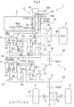
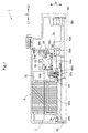
- Skeleton diagram of vehicle drive device The figure which shows the arrangement
- Speed diagram of transmission according to embodiment Partial sectional drawing of the vehicle drive device which concerns on embodiment Operation table of transmission according to embodiment Skeleton diagram of a part of a vehicle drive device according to another embodiment
- the vehicle drive device 1 includes a transmission 4 that can change a gear ratio, a rotating electrical machine 3, and a power transmission path that transmits a driving force to an output member 91 that is drivingly connected to wheels 9. It is equipped with.
- this power transmission path is a power transmission path that connects the input shaft 90 that is drivingly connected to the internal combustion engine 2 and the output member 91.
- the vehicle drive device 1 further includes a differential gear device 7 and a case 6.
- the transmission 4 and the rotating electrical machine 3 are accommodated in the case 6.
- the case 6 accommodates a differential gear device 7 in addition to the transmission 4 and the rotating electrical machine 3.
- the input shaft 90 corresponds to an “input member”.
- the rotating electrical machine 3 is connected to the rotor 3b so as to rotate integrally, and is a power transmission path (a power transmission path for transmitting a driving force to the output member 91.
- the input shaft 90 and the output member 91 is provided with an output gear 3a that meshes with a gear provided in a power transmission path connecting to 91).
- the output gear 3 a meshes with the drive gear mechanism 10.
- the rotating electrical machine 3 is electrically connected to a power storage device (not shown) such as a battery or a capacitor, and is powered by power supplied from the power storage device, or the torque of the internal combustion engine 2 or the inertial force of the vehicle. The electric power generated by is supplied to the power storage device to be stored.
- the output gear 3a corresponds to an “output rotating member”.
- the rotating electrical machine 3 is arranged on a different axis from the first transmission mechanism 41 and the second transmission mechanism 42, and is further arranged on a different axis from the drive gear mechanism 10 in this embodiment. That is, the speed change mechanism (the first speed change mechanism 41 and the second speed change mechanism 42 in the present embodiment) is disposed on a separate axis from the rotating electrical machine 3. Specifically, the first transmission mechanism 41 is arranged on a separate axis from the rotating electrical machine 3, and the second transmission mechanism 42 is arranged on a separate axis from the rotating electrical machine 3 and the first transmission mechanism 41.
- the rotating electrical machine 3 is on the first side L1 from the drive gear mechanism 10 and overlaps the drive gear mechanism 10 or a member that rotates integrally with the drive gear mechanism 10 when viewed in the axial direction L.
- the members that rotate integrally with the drive gear mechanism 10 include members that are arranged coaxially with the drive gear mechanism 10 (here, on the third axis A3) and that always rotate integrally with the drive gear mechanism 10. It is.
- the fifth clutch C5 (specifically, the output side engaging member of the fifth clutch C5) corresponds to such a member.
- a member that rotates integrally with the drive gear mechanism 10 is a member that is disposed coaxially with the drive gear mechanism 10 and that rotates integrally with the drive gear mechanism 10 while being connected to the drive gear mechanism 10. Can also be included.
- the input-side engaging member and the input shaft 90 of the fifth clutch C5 that rotate integrally with the drive gear mechanism 10 in a directly connected state of the fifth clutch C5 correspond to such a member.
- the rotating electrical machine 3 is disposed so as to overlap the drive gear mechanism 10 when viewed in the axial direction L (see FIG. 2).
- the rotating electrical machine 3 is arranged so that the first transmission mechanism 41 and the arrangement area in the axial direction L overlap, and the second transmission mechanism 42 and the arrangement area in the axial direction L overlap.
- at least a part of the rotating electrical machine 3 is disposed so as to overlap each of the first transmission mechanism 41 and the second transmission mechanism 42 when viewed in the radial direction R (the radial direction of the rotating electrical machine 3).
- at least a part of a shift drum 53 described later is disposed so as to overlap each of the first transmission mechanism 41 and the second transmission mechanism 42 when viewed in the radial direction R (the radial direction of the rotating electrical machine 3).
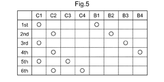
- the first speed change mechanism 41 forms an odd number of the plurality of forward speeds
- the second speed change mechanism 42 forms an even number of the plurality of forward speeds
- the odd-numbered gear is an odd-numbered gear when a plurality of forward gears are arranged in descending order of the gear ratio (in this embodiment, the first gear 1st, the third gear 3rd, and the fifth gear 5th).
- the even-numbered gear is an even-numbered gear when a plurality of forward gears are arranged in descending order of gear ratio (in this embodiment, second gear 2nd, fourth gear 4th, sixth gear 6th). It is. Therefore, as shown in FIG.
- the fifth clutch C5 is released when the electric travel mode is executed.
- the output gear 3a of the rotating electrical machine 3 is disposed closer to the input shaft 90 than the first clutch C1 and the second clutch C2 in the power transmission path between the input shaft 90 and the output member 91. It is connected to a member (specifically, drive gear mechanism 10). That is, the output gear 3a of the rotating electrical machine 3 is drivingly connected to the drive gear mechanism 10 without passing through the first clutch C1 and the second clutch C2. Therefore, by engaging the first clutch C1, the rotation of the rotating electrical machine 3 can be shifted by the first transmission mechanism 41 and transmitted to the output member 91, and by rotating the second clutch C2, the rotation can be performed.
- the first speed change mechanism 41 includes a first brake B1 that selectively fixes the third carrier CA3 to the case 6, and a third brake B3 that selectively fixes the first carrier CA1 and the third sun gear S3 to the case 6. And a third clutch C3 for selectively connecting the third carrier CA3 and the first carrier CA1 and the third sun gear S3.
- the second sleeve 82 and the fourth sleeve 84 are the sleeve 80 of the second meshing engagement device.
- the second sleeve 82 is a sleeve 80 common to the fourth brake B4 and the fourth clutch C4, and the fourth sleeve 84 is the sleeve 80 of the second brake B2.
- the state where the third brake B3 is engaged and the state where the third brake B3 is released are switched according to the position of the third sleeve 83 in the axial direction L. Further, the state in which the second brake B2 is engaged and the state in which the second brake B2 is released are switched according to the position of the fourth sleeve 84 in the axial direction L. As described above, the first sleeve 81 and the second sleeve 82 are switched in the position in the axial direction L between the three positions, and the third sleeve 83 and the fourth sleeve 84 are positioned in the two positions in the axial direction L. Can be switched between.
- the transmission driving device 5 includes a first shift fork 71 that transmits the operation of the cam mechanism to the first sleeve 81, a second shift fork 72 that transmits the operation of the cam mechanism to the second sleeve 82, There are provided four shift forks 70, a third shift fork 73 that transmits the operation of the cam mechanism to the third sleeve 83 and a fourth shift fork 74 that transmits the operation of the cam mechanism to the fourth sleeve 84.
- the shift fork 70 corresponds to the “transmission member”
- the first shift fork 71 and the third shift fork 73 correspond to the “first transmission member”
- the second shift fork 72 and the fourth shift fork 74 Corresponds to a “second transmission member”.
- the outer peripheral surface (cylindrical outer peripheral surface) of the shift drum 53 is referred to as a circumferential direction based on the rotational axis of the shift drum 53 (hereinafter referred to as “circumferential direction C”).
- a groove 50 (cam groove) is formed so as to extend.
- the groove part 50 is formed corresponding to each of the shift forks 70.
- Four groove portions 50 are formed on the outer peripheral surface of the shift drum 53.
- the shift fork 70 is connected to an engaging portion 60 that is slidably engaged with the groove portion 50 in the circumferential direction C.
- the engaging portion 60 is moved in the axial direction L in accordance with the shape of the groove portion 50 (meandering shape in which the position in the axial direction L changes according to the position in the circumferential direction C).
- the shift fork 70 connected to the engaging portion 60 is moved in the axial direction L.
- the shift fork 70 includes a fitting portion 63 (fork portion) that is slidably fitted into a groove formed on the outer peripheral surface of the sleeve 80, and the shift fork 70 is moved in the axial direction L.
- the sleeve 80 is moved in the axial direction L.
- the shift fork 70 transmits the operation of the engaging portion 60 accompanying the rotation of the shift drum 53 to the sleeve 80.
- a rotation position (set rotation position) corresponding to each gear position is set, and the shape of each groove portion 50 is set so that a corresponding gear position is formed at each set rotation position. Is set.
- the groove portion 50 for driving the sleeve 80 (81, 83) of the first meshing engagement device (B1, B3, C3) is defined as the first groove portion 51
- the second meshing engagement device (B2, B4). , C4), the groove 50 for driving the sleeve 80 (82, 84) is referred to as a second groove 52.
- the engaging portion 60 that is slidably engaged with the first groove portion 51 in the circumferential direction C is referred to as a first engaging portion 61, and is slidably engaged with the second groove portion 52 in the circumferential direction C.
- two first groove portions 51 and two second groove portions 52 are formed on the outer peripheral surface of the shift drum 53, and the two first engagement portions 61 and 2 are formed.
- Two second engaging portions 62 are engaged with the outer peripheral surface (groove portion 50) of the shift drum 53.
- the shift drive device 5 includes an actuator 54 that rotationally drives the shift drum 53 around the axial direction L.
- an electric motor can be used as the actuator 54.
- a drive gear 54 a provided on the output shaft of the actuator 54 and a driven gear 53 a provided on the shift drum 53 are connected via a reduction gear mechanism 55.
- the output rotation of 54 is decelerated by the reduction gear mechanism 55 and transmitted to the shift drum 53.
- the vehicle is provided with a control device that controls the vehicle drive device 1.
- the control device controls the drive of the actuator 54 and rotationally drives the shift drum 53.
- the shift stage to be formed is switched (shift change).
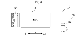
- the shift drum 53 is disposed so as to overlap the rotating electrical machine 3 when viewed in the axial direction L. That is, at least a part of the shift drum 53 is arranged at a position overlapping the rotating electrical machine 3 when viewed in the axial direction L. In the present embodiment, the entire shift drum 53 is disposed at a position overlapping the rotating electrical machine 3 when viewed in the axial direction L.
- the shift drum 53 is arrange
- the shift drum 53 is rotatable relative to the rotating electrical machine 3 between the rotating electrical machine 3 (rotor core) and the output gear 3a in the axial direction L (that is, does not hinder the rotation of the rotating electrical machine 3). Is in place).
- the shift drum 53 is disposed at a position at least partially overlapping with the rotating electrical machine 3 when viewed in the axial direction L, and is disposed between the rotor 3b (rotor core) and the output gear 3a in the axial direction L. Yes.
- the shift drum 53 is formed in a cylindrical shape extending in the axial direction L, and the rotor 3b and the output gear 3a of the rotating electrical machine 3 are formed in a space defined by the cylindrical inner peripheral surface of the shift drum 53. Is inserted in the axial direction L. In the example shown in FIG.
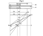
- the first axis A1 where the first transmission mechanism 41 is arranged and the second axis A2 where the second transmission mechanism 42 is arranged are viewed in the axial direction L.
- the first imaginary straight line X1 connecting the axis of the shift drum 53 (in this example, the fifth axis A5) and the axis of the output member 91 (in this example, the fourth axis A4) is disposed on the opposite side. Has been.
- the shaft center of the first meshing engagement device (B1, B3, C3) and the second meshing engagement device (B2) can be arranged at a position where the distance is approximately the same (distance in the axial direction L view) from each of the shaft centers of B4 and C4).
- the sleeves 80 of the first meshing engagement device and the second meshing engagement device arranged on different shafts by the common shift drum 53 with a relatively simple configuration.
- the first axis A1 and the second axis A2 are arranged with respect to the position in the direction parallel to the first imaginary straight line X1.
- 5 axes A5) are located on the same side with respect to each other, and are further located on the same side with respect to the axis of the drive gear mechanism 10 (in this example, the third axis A3).
- either the rotating electrical machine 3 or the shift drum 53 is parallel to the first virtual line X1 and on the same side as the first axis A1 with respect to the first virtual line X1.
- a virtual straight line in contact with the outer periphery of the larger diameter is defined as a second virtual straight line X2, which is parallel to the first virtual straight line X1 and the second axis A2 with respect to the first virtual straight line X1.
- a virtual straight line that is in contact with the outer circumference of the rotating electrical machine 3 or the shift drum 53 (in this embodiment, the rotating electrical machine 3) on the same side as the third virtual straight line X3 is orthogonal to the first virtual straight line X1.
- the shift drum 53 is disposed so as to overlap the rotating electrical machine 3 when viewed in the axial direction L, and the rotating electrical machine 3 is generally a relatively large-diameter device as shown in FIG. Therefore, it is possible to ensure a large diameter of the shift drum 53 while suppressing an increase in the size of the vehicle drive device 1 in a direction orthogonal to the axial direction L.
- the first shift fork 71 and the second shift fork 72 switch the position of the corresponding sleeve 80 in the axial direction L between three positions
- the third shift fork 73 and the fourth shift fork 74 are The position of the corresponding sleeve 80 in the axial direction L is switched between the two positions. Therefore, the first groove 51 that the first engagement portion 61 of the first shift fork 71 engages and the second groove 52 that the second engagement portion 62 of the second shift fork 72 engages are the engagement portion 60.
- the first groove portion 51 engaged with the first engagement portion 61 of the third shift fork 73 and the second engagement of the fourth shift fork 74 are formed so as to switch the position in the axial direction L between the three positions.
- the 2nd groove part 52 with which the joint part 62 engages is formed in the shape which switches the position of the axial direction L of the engaging part 60 between two positions. And in this embodiment, the 1st groove part 51 and the 2nd groove part 52 in which the number of the positions of the axial direction L where the engaging part 60 is switched are mutually the same are provided along with the circumferential direction C.
- the shift drum 53 is disposed between the rotor 3b and the output gear 3a in the axial direction L. Since the output gear 3a is disposed on the second side L2 with respect to the rotor 3b, the shift drum 53 is disposed on the second side L2 with respect to the rotor 3b and on the first side L1 with respect to the output gear 3a. ing.
- the arrangement configuration of the shift drum 53 in the vehicle drive device 1 of the present embodiment will be described with reference to FIG.
- connection part 92c is a connection part by spline engagement.
- the spline teeth formed on the inner peripheral surface of one of the first shaft portion 92a and the second shaft portion 92b (the first shaft portion 92a in the example shown in FIG. 4), the first shaft portion 92a and the second shaft portion 92b
- the spline teeth formed on the outer peripheral surface of the other of the two shaft portions 92b (the second shaft portion 92b in the example shown in FIG. 4) are engaged with each other at the connecting portion 92c, whereby the first shaft portion 92a and the second shaft portion.
- the rotation sensor 93 that detects the rotation of the rotating electrical machine 3 is arranged on the opposite side of the connecting portion 92c with respect to the rotor 3b in the axial direction L (that is, the first side L1 with respect to the rotor 3b).
- the rotation sensor 93 is a sensor for detecting the rotational position of the rotor 3b with respect to the stator 3c, and a resolver is used as the rotation sensor 93 in the example shown in FIG.
- the vehicle drive device 1 includes a first rotor bearing 98a, a second rotor bearing 98b, a third rotor bearing 98c, and a fourth rotor bearing 98d as bearings for rotatably supporting the rotor shaft 92. .
- These bearings (98a, 98b, 98c, 98d) are radial bearings that can receive a load in the radial direction R, and in this embodiment, ball bearings are used.
- the first rotor bearing 98a is disposed on the second side L2 with respect to the rotor 3b, and supports the first shaft portion 92a from the outer side in the radial direction R so as to be rotatable with respect to the case 6.
- the second rotor bearing 98b is disposed on the first side L1 with respect to the output gear 3a, and supports the second shaft portion 92b from the outside in the radial direction R so as to be rotatable with respect to the case 6.
- the third rotor bearing 98c is disposed on the first side L1 with respect to the rotor 3b, and supports the first shaft portion 92a from the outer side in the radial direction R so as to be rotatable with respect to the case 6.
- the fourth rotor bearing 98d is disposed on the second side L2 with respect to the output gear 3a, and supports the second shaft portion 92b from the outside in the radial direction R so as to be rotatable with respect to the case 6.
- the 1st rotor bearing 98a is arrange
- the first shaft portion 92a is rotatably supported by the first rotor bearing 98a
- the second shaft portion 92b is rotatably supported by the second rotor bearing 98b.
- the first rotor bearing 98a and the second rotor bearing 98b correspond to “rotor bearings”.
- the cylindrical support member 56 includes a main body portion 56a and a support portion 56c.
- the main body portion 56 a is a portion (cylindrical portion extending in the axial direction L) disposed in a space surrounded by the cylindrical inner peripheral surface of the shift drum 53, and is radial with respect to the inner peripheral surface of the shift drum 53. It has a cylindrical outer peripheral surface facing (in the radial direction with respect to the axis of the shift drum 53, which is the same as the radial direction R in this embodiment).
- the support portion 56c is a portion (a portion to be fixed) that supports the main body portion 56a with respect to a fixing member (the case 6 itself or a member fixed to the case 6).
- the main body portion 56a and the fixing member are provided so as to be connected to each other.
- the support portion 56c is formed so as to extend along the radial direction R (here, parallel to the radial direction R).
- the main body portion 56a is disposed on the second side L2 with respect to the support portion 56c.
- a wall portion provided in the case 6 (specifically, a wall portion provided between the rotor 3b and the output gear 3a in the axial direction L to support the rotor shaft 92), It is used as the support part 56c.
- a rotor bearing (a first rotor bearing 98a and a second rotor bearing 98b) that rotatably supports the rotor shaft 92 is disposed between the inner peripheral surface of the cylindrical support member 56 and the outer peripheral surface of the rotor shaft 92. ing. Specifically, the first rotor bearing 98a is disposed between the inner peripheral surface of the cylindrical support member 56 and the outer peripheral surface of the first shaft portion 92a. That is, the first rotor bearing 98a and the first rotor bearing 98a on the inner peripheral surface of the cylindrical support member 56 overlap with the portion where the arrangement region in the axial direction L overlaps (the portion overlapping the first rotor bearing 98a in the radial direction R view).
- a cylindrical first bearing support surface having a diameter corresponding to the outer diameter is formed.
- the first bearing support surface is formed at the inner end portion in the radial direction R of the support portion 56 c.
- the second rotor bearing 98b is disposed between the inner peripheral surface of the cylindrical support member 56 and the outer peripheral surface of the second shaft portion 92b. That is, the second rotor bearing 98b and the second rotor bearing 98b on the inner peripheral surface of the cylindrical support member 56 overlap with the portion where the arrangement region in the axial direction L overlaps (the portion that overlaps the second rotor bearing 98b when viewed in the radial direction R).
- a cylindrical second bearing support surface having a diameter corresponding to the outer diameter is formed.
- the portion on the first side L1 of the second bearing support surface is formed at the inner end portion in the radial direction R of the main body portion 56a, and the second side L2 of the second bearing support surface. Is an end portion on the inner side in the radial direction R in a portion (a portion where a regulating portion 56b described later is formed on the outer side in the radial direction R) located on the second side L2 with respect to the main body portion 56a in the cylindrical support member 56. Is formed.
- both the support of the rotor shaft 92 and the support of the shift drum 53 are performed by using the inner peripheral surface and the outer peripheral surface of one cylindrical support member 56.
- the cylindrical support member 56 includes a restricting portion 56 b that protrudes radially outward on both sides in the axial direction L with respect to the shift drum 53 and restricts the movement range of the shift drum 53 in the axial direction L. ing.
- the restricting portion 56b is in the radial direction with respect to the outer peripheral surface of the main body portion 56a on each of both sides in the axial direction L with respect to the main body portion 56a (in the radial direction with reference to the axis of the shift drum 53) In this case, the projections are provided so as to protrude outward in the radial direction R).
- a regulating surface is formed that contacts the end surface of the shift drum 53 in the axial direction L and regulates the movement of the shift drum 53 in the axial direction L.
- the restricting portion 56b on the first side L1 is formed by a portion located on the outer side in the radial direction R with respect to the outer peripheral surface of the main body portion 56a in the support portion 56c.
- the cylindrical support member 56 has a portion formed integrally with the main body portion 56 a so as to be positioned on the second side L ⁇ b> 2 with respect to the main body portion 56 a, and the diameter at the portion.
- the outer side portion in the direction R forms a restricting portion 56b on the second side L2. That is, in the example shown in FIG. 4, the restricting portion 56b on the first side L1 is configured by a member different from the main body portion 56a, and the restricting portion 56b on the second side L2 is formed integrally with the main body portion 56a. Yes.
- the shift drum 53 has one of the first rotor bearing 98a and the second rotor bearing 98b (specifically, the second rotor bearing 98b) and the radial direction R (the radial direction of the shift drum 53).
- the configuration arranged so as to overlap with each other has been described as an example.
- the present invention is not limited to such a configuration, and the shift drum 53 is disposed so as to overlap the first rotor bearing 98a in the radial direction R.
- the shift drum 53 includes the first rotor bearing 98a and the second rotor.
- the portion including the end portion of the first side L1 of the shift drum 53 is the same as the portion including the end portion of the second rotor L2 of the first rotor bearing 98a in the radial direction R (the radial direction of the shift drum 53).
- the portion including the end portion on the second side L2 of the shift drum 53 overlaps the portion including the end portion on the first side L1 of the second rotor bearing 98b in the radial direction R.
- the main body 56a is disposed on the first side L1 with respect to the support 56c, and the main body 56a and the support 56c are integrally formed. Is formed.
- the support part 56c is comprised by the member different from the case 6, and the support part 56c is being fixed with the fastening member (this example fastening bolt) with respect to the case 6 (periphery wall part).
- the restricting portion 56b on the first side L1 is configured by a member different from the main body portion 56a.
- the cylindrical support member 56 includes a cylindrical member that is externally fitted to an end portion of the first side L1 of the member that constitutes the main body portion 56a.
- a restricting portion 56b is formed.
- This cylindrical member is also used as an attachment portion of the rotation sensor 93.
- the sensor stator of the rotation sensor 93 is attached to the cylindrical member from the first side L1.
- the configuration in which the cylindrical support member 56 includes the restricting portion 56b has been described as an example.
- the present invention is not limited to such a configuration, and when the movement range of the shift drum 53 in the axial direction L is restricted by another member or another mechanism, the cylindrical support member 56 is disposed on both sides in the axial direction L. It can also be set as the structure which is not provided with at least one of the control parts 56b.
- the configuration in which the shift drum 53 is disposed coaxially with the rotating electrical machine 3 has been described as an example.
- the present invention is not limited to such a configuration, and the shift drum 53 is arranged on a separate axis from the rotating electrical machine 3 at a position at least partially overlapping the rotating electrical machine 3 when viewed in the axial direction L. You can also.
- the shift drum 53 is arranged on a different axis (hereinafter referred to as “sixth axis”) from the rotating electrical machine 3, the inner peripheral surface of one cylindrical support member 56 is similar to the above embodiment.
- the inner peripheral surface of the cylindrical support member 56 (at least the portion that supports the rotor bearing from the radially outer side).
- the peripheral surface is formed in a cylindrical shape having the fifth axis A5 as an axis
- the outer peripheral surface of the cylindrical support member 56 (main body portion 56a) is formed in a cylindrical shape having the sixth axis as an axis. That is, the fifth axis A5 that is the axis of the inner peripheral surface of the cylindrical support member 56 is arranged eccentrically with respect to the sixth axis that is the axis of the outer peripheral surface of the cylindrical support member 56.
- the rotor shaft 92 does not penetrate the shift drum 53 in the axial direction L, that is, the rotor shaft 92 as viewed in the axial direction L. It is also possible to adopt a configuration in which the arrangement area of the shift drum 53 and the arrangement area of the shift drum 53 do not overlap. In the above embodiment, the configuration in which the diameter of the outer peripheral surface of the shift drum 53 is smaller than the diameter of the outer peripheral surface of the rotating electrical machine 3 has been described as an example.
- the diameter of the outer peripheral surface of the shift drum 53 is not limited to such a configuration, and the diameter of the outer peripheral surface of the shift drum 53 is the same as the diameter of the outer peripheral surface of the rotary electric machine 3. 3 may be larger than the diameter of the outer peripheral surface 3.
- the rotor shaft 92 includes the first shaft portion 92a to which the rotor 3b is fixed, and the second shaft portion 92b to which the output gear 3a is fixed.
- the biaxial portion 92b has been described as an example of a configuration in which the two shaft portions 92b are formed of separate members and are connected via the connecting portion 92c.
- the configuration is not limited to such a configuration, and a portion corresponding to the first shaft portion 92a and a portion corresponding to the second shaft portion 92b in the rotor shaft 92 may be integrally formed. .
- the shift drum 53 having a length in the axial direction L shorter than the distance in the axial direction L between the end surface of the second side L2 of the rotor 3b and the end surface of the first side L1 of the output gear 3a is used.
- the shift drum 53 can be disposed between the rotor 3b and the output gear 3a in the axial direction L as in the above embodiment.
- the configuration in which the first groove portion 51 and the second groove portion 52 are provided side by side in the circumferential direction C has been described as an example.
- the configuration is not limited to such a configuration, and the first groove portion 51 and the second groove portion 52 may be provided at different positions in the axial direction L.
- a configuration in which the plurality of first groove portions 51 are provided side by side in the circumferential direction C, a configuration in which the plurality of second groove portions 52 are provided in the circumferential direction C, and all the groove portions 50 formed in the shift drum 53 are in the circumferential direction. It can also be set as the structure provided along with C, etc.
- the second virtual line X2, the third virtual line X3, the fourth virtual line X4, and the fifth virtual line The configuration arranged in the region surrounded by the straight line X5 has been described as an example. However, without being limited to such a configuration, one or both of the first axis A1 and the second axis A2 may be the second virtual line X2, the third virtual line X3, the fourth virtual line X4, and the fifth virtual line. It can also be set as the structure arrange
- the first shaft A1 where the first transmission mechanism 41 is disposed and the second shaft A2 where the second transmission mechanism 42 is disposed are viewed in the axial direction L and the shift drum 53 Opposite to each other across a first imaginary straight line X1 connecting the axis (in the example of the above embodiment, the fifth axis A5) and the axis of the output member 91 (in the example of the above embodiment, the fourth axis A4).
- the arrangement to be arranged has been described as an example.
- the present invention is not limited to such a configuration, and the first axis A1 and the second axis A2 are arranged on the same side with respect to the first virtual straight line X1 when viewed in the axial direction L. You can also.
- the transmission 4 includes the first meshing engagement device (B1, B3, C3) and the second meshing engagement device (B2, B4, C4), and the transmission driving device.
- 5 is a shift fork 70 (71, 73) that transmits the operation of the cam mechanism according to the rotation of the shift drum 53 to the sleeve 80 (81, 83) of the first meshing engagement device, and the rotation of the shift drum 53.
- the configuration including the shift fork 70 (72, 74) that transmits the operation of the corresponding cam mechanism to the sleeve 80 (82, 84) of the second meshing engagement device has been described as an example.
- the present invention is not limited to such a configuration, and the speed change drive device 5 is configured to include a second shift drum different from the shift drum 53, and the speed change drive device 5 has a cam corresponding to the rotation of the shift drum 53.
- the shift fork 70 transmitting the operation of the mechanism to the sleeve 80 of the second meshing engagement device
- the operation of the cam mechanism according to the rotation of the second shift drum is applied to the sleeve 80 of the second meshing engagement device. It can also be set as the structure provided with the shift fork transmitted.
- the configuration in which the output gear 3a of the rotating electrical machine 3 is engaged with the drive gear mechanism 10 has been described as an example.
- the present invention is not limited to such a configuration, and the output gear 3a of the rotating electrical machine 3 and the drive gear mechanism 10 can be driven and connected via another transmission member (such as an idler gear).
- the output gear 3a of the rotating electrical machine 3 is meshed with the first driven gear 21 or the second driven gear 22, that is, the output gear 3a of the rotating electrical machine 3 is the first driven gear 21 or the second driven gear.
- a configuration may be adopted in which the drive gear mechanism 10 is drivingly connected via the gear 22.
- the output gear 3a of the rotating electrical machine 3 is disposed on the input shaft 90 side of the speed change mechanism (the first speed change mechanism 41 and the second speed change mechanism 42) in the power transmission path connecting the input shaft 90 and the output member 91. It is configured not to be a member (in the above embodiment, the drive gear mechanism 10) but to be connected to a member (for example, the output member 91) disposed on the output member 91 side of the speed change mechanism in the power transmission path. You can also. In such a case, unlike the above embodiment, the output gear 3a of the rotating electrical machine 3 is drivingly connected to the drive gear mechanism 10 via at least one of the first clutch C1 and the second clutch C2. Become.
- the configuration in which the rotating electrical machine 3 is disposed on a different shaft from the drive gear mechanism 10 has been described as an example.
- the configuration is not limited to such a configuration, and the rotary electric machine 3 may be arranged coaxially with the drive gear mechanism 10.
- the output gear 3a of the rotating electrical machine 3 may be connected so as to rotate integrally with the drive gear mechanism 10.
- the output rotating member of the rotating electrical machine 3 is not the output gear 3a but a shaft member that rotates integrally with the rotor 3b of the rotating electrical machine 3. You can also.
- the drive gear mechanism 10 is configured by the common drive gear that meshes with both the first driven gear 21 and the second driven gear 22
- the drive gear mechanism 10 includes a first drive gear that meshes with the first driven gear 21 and a second drive gear that meshes with the second driven gear 22. It can also be configured.
- the first speed change mechanism 41 changes the speed of the rotation of the first drive gear included in the drive gear mechanism 10 and transmits it to the output member 91
- the second speed change mechanism 42 is the second drive gear included in the drive gear mechanism 10. Is rotated and transmitted to the output member 91.
- the first clutch C1 is replaced with a power transmission path between the drive gear mechanism 10 and the first transmission mechanism 41.
- the input shaft 90 is provided in the power transmission path between the first drive gear and the second clutch C2 is replaced with the power transmission path between the drive gear mechanism 10 and the second speed change mechanism 42.
- a second power transmission path between the first drive gear and the second drive gear a first clutch C1 connects or disconnects the input shaft 90 and the first drive gear
- the second clutch C2 connects or disconnects the input shaft 90 and the second drive gear.
- the output gear 3a of the rotating electrical machine 3 is set to one of the first drive gear and the second drive gear. It can be set as a meshing structure.
- the configuration in which the vehicle drive device 1 includes the fifth clutch C5 has been described as an example.
- the present invention is not limited to such a configuration, and the vehicle drive device 1 may not include the fifth clutch C5, and the input shaft 90 and the drive gear mechanism 10 may always rotate integrally.
- the power transmission path in which the transmission 4 and the rotating electrical machine 3 are provided is a power transmission path that connects the input shaft 90 that is drivingly connected to the internal combustion engine 2 and the output member 91. Described as an example.
- the present invention is not limited to such a configuration, and a configuration in which the output torque of the internal combustion engine 2 (input shaft 90) is not transmitted to a power transmission path in which the transmission 4 and the rotating electrical machine 3 are provided (for example, a vehicle drive device). 1 may be configured not to include the input shaft 90 and the fifth clutch C5 shown in FIG. That is, the vehicle drive device 1 can be a drive device for an electric vehicle (electric vehicle) instead of a drive device for a hybrid vehicle.
- the configurations of the first transmission mechanism 41 and the second transmission mechanism 42 shown in the above embodiment are merely examples, and specific configurations of the first transmission mechanism 41 and the second transmission mechanism 42 (the planetary gear mechanism used)
- the type single pinion type, double pinion type, Ravigneaux type, etc.
- the number of planetary gear mechanisms used the arrangement of the engaging devices for each rotating element, etc. can be changed as appropriate.
- the transmission 4 provided in the vehicle drive device 1 has two transmission mechanisms (the first transmission mechanism 41 and the second transmission mechanism 42) and two for switching between the two transmission mechanisms.
- the configuration provided with the engagement devices has been described as an example.
- the technology according to the present disclosure can be applied to the vehicle drive device 1 including the transmission 4 having another configuration without being limited to such a configuration.
- the other configurations of the transmission 4 include all configurations including at least one meshing engagement device.
- the transmission 4 includes a parallel-shaft gear-type transmission mechanism or a transmission mechanism.
- a transmission in which all the planetary gear mechanisms are coaxially arranged can be exemplified. Specifically, as an example, in the configuration of FIG.
- the transmission 4 includes the drive gear mechanism 10, the first driven gear 21, the first transmission mechanism 41, and the first output gear 31.
- the transmission 4 can be configured not to include the second driven gear 22, the second transmission mechanism 42, the second output gear 32, the first clutch C1, and the second clutch C2. That is, the transmission 4 is configured to include only one of the first transmission mechanism 41 and the second transmission mechanism 42 in the above embodiment (that is, the transmission 4 includes only one transmission mechanism). Can do.
- the rotating electrical machine 3 is an inner rotor type rotating electrical machine
- the rotating electrical machine 3 may be an outer rotor type rotating electrical machine, or the rotating electrical machine 3 may be an axial gap type rotating electrical machine instead of a radial gap type.
- the transmission (4) includes at least one meshing engagement device (B1 to B4, C3, C4) and the meshing engagement device (B1 to B4, C3).
- the shift drum (53) and the rotating electrical machine (3) As a result, the region where only the shift drum (53) is disposed in the axial direction (L) can be reduced. Thereby, it becomes possible to arrange
- the transmission (4) is a driving gear to which at least one of the rotational driving force of the rotating electrical machine (3) and the rotational driving force of the input member (90) connected to the internal combustion engine (2) is transmitted. It is preferable to provide the mechanism (10).
- the rotational driving force of the driving force source (2, 3) can be appropriately input to the transmission (4).
- the transmission changes the rotation of the drive gear mechanism (10) and transmits the rotation to the output member (91). It is preferable that the first transmission mechanism (41) and the second transmission mechanism (42), which are two transmission mechanisms (41, 42), are provided.
- the degree of freedom in setting the transmission ratio of the transmission (4) and the degree of freedom in the layout of the transmission (4) are compared with the case where the transmission (4) includes only one transmission mechanism. , It will be easier to secure both sides.
- the transmission (4) includes the first transmission mechanism (41) and the second transmission mechanism (42) as described above
- the first transmission mechanism (41) is connected to the rotating electrical machine (3).
- the second transmission mechanism (42) is preferably disposed on a separate shaft from the rotating electrical machine (3) and the first transmission mechanism (41).
- the transmission mechanism (41, 42) and the rotating electrical machine (3) can be easily disposed close to the axial direction (L) and at the same time in the radial direction (R) of the rotating electrical machine (3).
- the rotating electrical machine (3) can be arranged so as to overlap the transmission mechanism (41, 42) as seen, and the entire apparatus can be reduced in the axial direction (L).
- the first speed change mechanism (41) is arranged on a separate shaft from the rotating electrical machine (3), and the second speed change mechanism (42) is arranged on the rotating electrical machine (3) and the first speed change mechanism ( 41), in which the rotating electrical machine (3) includes at least a part of the first speed change mechanism (41) and the first transmission mechanism (41) when viewed in the radial direction (R) of the rotating electrical machine (3). It is preferable that the second transmission mechanism (42) is disposed so as to overlap each other.
- the rotating electrical machine (3) is seen in the radial direction (R) of the rotating electrical machine (3), and each of the first transmission mechanism (41) and the second transmission mechanism (42).
- the shift drum (53) is arranged coaxially with the rotating electrical machine (3), and at least a part of the shift drum (53) has a diameter of the rotating electrical machine (3). It is preferable that the first transmission mechanism (41) and the second transmission mechanism (42) are disposed so as to overlap each other when viewed in the direction (R).
- the shift drum (53) is arranged so as not to overlap with either the first transmission mechanism (41) or the second transmission mechanism (42) when viewed in the radial direction (R). It is possible to reduce the size of the entire apparatus in the axial direction (L).
- the first speed change mechanism (41) is arranged on a separate shaft from the rotating electrical machine (3), and the second speed change mechanism (42) is arranged on the rotating electrical machine (3) and the first speed change mechanism ( 41),
- the first transmission mechanism (41) includes a first meshing engagement device (B1, B3, C3) that is the meshing engagement device
- the two speed change mechanism (42) includes a second meshing engagement device (B2, B4, C4)
- the speed change drive device (5) is the shift drum (53) of the cam mechanism formed by the shift drum (53). ) Is transmitted to the engaging members (81, 83) of the first meshing engagement devices (B1, B3, C3).
- a second transmission member (72, 74) which is a transmission member (70) for transmitting the operation to the engagement member (82, 84) of the second meshing engagement device (B2, B4, C4). It is preferable that
- the engagement members (80) of the first meshing engagement devices (B1, B3, C3) and the second meshing engagement devices (B2, B4, C4) disposed on different axes from each other. ) Can be driven by a common shift drum (53). Therefore, the shift drum for driving the engagement member (80) of the first meshing engagement device (B1, B3, C3) and the engagement member of the second meshing engagement device (B2, B4, C4) Compared with the case where a shift drum for driving (80) is provided separately, the entire apparatus can be reduced in size, and the number of parts and cost can be reduced.
- the first speed change mechanism (41) The rotation of the drive gear mechanism (10) is changed at different speed ratios depending on the state of the engagement members (81, 83) of the first meshing engagement device (B1, B3, C3), and the output member ( 91), the second transmission mechanism (42) is disposed on a second shaft (A2) different from the first shaft (A1) on which the first transmission mechanism (41) is disposed, and The output member is configured to change the rotation of the drive gear mechanism (10) at a different gear ratio according to the state of the engagement member (82, 84) of the second meshing engagement device (B2, B4, C4).
- the first axis (A1) and the second axis (A2) When viewed in the direction (L), they are preferably arranged on opposite sides across a first virtual straight line (X1) connecting the axis of the shift drum (53) and the axis of the output member (91). It is.
- the first meshing engagement device (B1, B1) is positioned at the same distance from the first shaft (A1) and the second shaft (A2) when viewed in the axial direction (L).
- B3, C3) and the second meshing engagement device (B2, B4, C4) from the center of each of the shift drums (53) at the same distance in the axial direction (L).
- An axis can be arranged.
- the combined member (80) can be driven by the common shift drum (53).
- the first axis (A1) and the second axis (A2) are arranged on opposite sides of the first virtual straight line (X1) when viewed in the axial direction (L).
- the rotary electric machine on the same side as the first axis (A1) parallel to the first virtual line (X1) and on the same side as the first axis (A1) with respect to the axial direction (L).
- a virtual straight line in contact with the outer periphery of the larger one of the diameters of the shift drum (53) is defined as a second virtual straight line (X2), which is parallel to the first virtual straight line (X1) and the first virtual line
- a virtual straight line in contact with the outer circumference of the rotating electrical machine (3) or the shift drum (53) having the larger diameter on the same side as the second axis (A2) with respect to the straight line (X1) is defined as a third virtual straight line ( X3) and perpendicular to the first imaginary straight line (X1) and the shift drum 53) is a fourth virtual straight line (X4), and a virtual straight line orthogonal to the first virtual straight line (X1) and passing through the axial center of the output member (91) is a fifth virtual straight line ( X5), when the first axis (A1) and the second axis (A2) are viewed in the axial direction (L), the second virtual line (X2), the third virtual line (X3), It is preferable that they are arranged in a region
- the separation distance can be set to a similar distance. Therefore, the axial centers of the rotating electrical machine (3) and the shift drum (53) are arranged at positions that are approximately the same distance from the first axis (A1) and the second axis (A2) when viewed in the axial direction (L). It becomes easy to do.
- the first transmission member (71, 73) A first engagement that is slidably engaged in the circumferential direction (C) with respect to a first groove (51) formed on the outer peripheral surface of the shift drum (53) so as to extend in the circumferential direction (C).
- the engagement member of the first meshing engagement device (B1, B3, C3) is connected to the portion (61), and the operation of the first engagement portion (61) accompanying the rotation of the shift drum (53)
- the second transmission member (72, 74) is formed on the outer peripheral surface of the shift drum (53) so as to extend in the circumferential direction (C).
- the second engaging portion (62) that is slidably engaged in the circumferential direction (C).
- the operation of the second engagement portion (62) accompanying the rotation of the shift drum (53) is transmitted to the engagement members (82, 84) of the second meshing engagement devices (B2, B4, C4).
- the first groove portion (51) and the second groove portion (52) are provided side by side in the circumferential direction (C).
- the first groove portion (51) and the second groove portion (52) in the axial direction (L) of the shift drum (53) are compared with the case where the first groove portion (51) and the second groove portion (52) are provided at different positions in the axial direction (L).
- the length can be kept short.
- the rotating electrical machine (3) is generally a device having a relatively large diameter, and the shift drum (53) is arranged so as to overlap with the rotating electrical machine (3) as viewed in the axial direction (L) as described above.
- the diameter of the shift drum (53) is reduced between the first groove portion (51) and the second groove portion (52) in the circumferential direction (C) while suppressing the enlargement of the entire apparatus in the direction orthogonal to the axial direction (L). It is possible to secure a large extent to be provided side by side.
- At least a part of the transmission member (70) is arranged so as to overlap the drive gear mechanism (10) when viewed in the axial direction (L).
- the transmission member (70) overlaps the drive gear mechanism (10) when viewed in the axial direction (L), the region where only the transmission member (70) is disposed when viewed in the axial direction (L) is reduced. Can be reduced. Therefore, in addition to the shift drum (53), the transmission member (70) driven by the shift drum (53) can be arranged while suppressing an increase in the size of the entire apparatus in the direction orthogonal to the axial direction (L).
- the transmission (4) includes the drive gear mechanism (10) and the A first clutch (C1) that connects or disconnects the first transmission mechanism (41), and a second clutch (C2) that connects or disconnects the drive gear mechanism (10) and the second transmission mechanism (42).
- the output rotating member (3a) of the rotating electrical machine (3) is drivingly connected to the driving gear mechanism (10) without passing through the first clutch (C1) and the second clutch (C2). It is preferable that
- the shift drum (53) can be arranged while suppressing an increase in the size of the entire apparatus in the direction orthogonal to the axial direction (L).
- the transmission (4) shifts the rotation of the drive gear mechanism (10) and the output member (91). It is preferable that the transmission mechanism is disposed on a separate shaft from the rotating electrical machine (2).
- the transmission mechanism and the rotating electrical machine (3) it is easy to dispose the transmission mechanism and the rotating electrical machine (3) close to the axial direction (L), and the transmission mechanism and the rotating electrical machine (3) are viewed in the radial direction (R).
- the rotating electrical machines (3) can be arranged so as to overlap each other, and the entire apparatus can be reduced in the axial direction (L).
- the speed change mechanism is disposed on a different axis from the rotating electrical machine (2)
- at least a part of the rotating electrical machine (3) is in the radial direction (R) of the rotating electrical machine (3). It is preferable that it is arranged so as to overlap with the speed change mechanism.
- the transmission (4) includes the drive gear mechanism (10) as described above, at least a part of the shift drum (53) is seen in the axial direction (L) and the drive gear mechanism (10 It is preferable that they are arranged so as to overlap with each other.
- the shift drum (53) is disposed coaxially with the rotating electrical machine (3).
- the support structure for rotatably supporting the shift drum (53) is compared with the case where the shift drum (53) is arranged on a different axis from the rotary electric machine (3). It becomes easy to share a part with the structure, and accordingly, it is easy to reduce the size and cost of the vehicle drive device (1).
- the diameter of the outer peripheral surface of the shift drum (53) is smaller than the diameter of the outer peripheral surface of the rotating electrical machine (3).
- the rotating electrical machine (3) is connected to the rotor (3b) and the rotor (3b) so as to rotate integrally therewith and is provided in the power transmission path.
- an output gear (3a) meshing with the gear, and the shift drum (53) is disposed between the rotor (3b) and the output gear (3a) in the axial direction (L). It is preferable.
- the shift drum (53) is disposed at a position overlapping the rotating electrical machine (3) when viewed in the axial direction (L), and in such an arrangement, the rotating electrical machine (3) and the shift drum are disposed. Since (53) is aligned in the axial direction (L), the apparatus is easily increased in size in the axial direction (L).
- the rotor (3b) and the output gear (3a) as rotating bodies included in the rotating electrical machine (3) must be supported by a rotation support structure such as a bearing or a support member of the bearing, and such rotation
- the support structure is often arranged side by side with the rotor (3b) in the axial direction (L).
- the shift drum (53) is disposed between the rotor (3b) and the output gear (3a) in the axial direction (L), the axial direction necessary for the arrangement of these rotation support structures is provided.
- the shift drum (53) can be arranged using the space (L). Therefore, the enlargement of the apparatus in the axial direction (L) can be limited.
- the enlargement as a whole of the vehicle drive device (1) provided with the rotary electric machine (3) and the shift drum (53) can be suppressed.
- the shift drum (53) is arranged coaxially with the rotating electrical machine (3), and a rotor shaft (92) that connects the rotor (3b) and the output gear (3a) includes the shift drum. It is preferable that (53) is penetrated in the axial direction (L).
- the rotating electrical machine (3) rotates integrally with the rotor (3b) and the rotor (3b).
- a rotor shaft (92) disposed between the output gear (3a) and connecting the rotor (3b) and the output gear (3a) passes through the shift drum (53) in the axial direction (L). It is preferable to do so.
- the shift drum (53) is disposed between the rotor (3b) and the output gear (3a) in the axial direction (L), and the rotor (3b) and the output gear (3a) are connected to each other. Since the connecting rotor shaft (92) passes through the shift drum (53) in the axial direction (L), the axial direction required for the arrangement of the rotation support structure of the rotor (3b) and the output gear (3a)
- the shift drum (53) can be arranged using the space (L). Therefore, the enlargement of the axial direction (L) of the apparatus due to the rotating electric machine (3) and the shift drum (53) being arranged in the axial direction (L) can be limited. As a result, the overall size of the vehicle drive device (1) including the rotating electrical machine (3) and the shift drum (53) can be suppressed.
- the shift drum (53) is disposed coaxially with the rotating electrical machine (3), and the rotor shaft (92) penetrates the shift drum (53) in the axial direction (L).
- a cylindrical support member (56) is disposed on the radially inner side of the shift drum (53) through the shift drum (53) in the axial direction (L), and the cylindrical support member (56).
- the cylindrical support member (56) is disposed on the radially inner side of the shift drum (53) as described above, the cylindrical support member (56) is It is preferable that a restricting portion (56b) that protrudes radially outward on both sides in the axial direction (L) and restricts the movement range of the shift drum (53) in the axial direction (L) is suitable.
- the movement of the shift drum (53) in the axial direction (L) can also be regulated by the cylindrical support member (56). Therefore, compared with the case where such movement restriction is performed by a member different from the cylindrical support member (56), it is easier to reduce the size and cost of the vehicle drive device (1).
- the rotating electrical machine (3) As a rotor shaft (92) for connecting the rotor (3b) and the output gear (3a), a first shaft portion (92a) to which the rotor (3b) is fixed and the output gear (3a) are fixed.
- a second shaft portion (92b), and the first shaft portion (92a) and the second shaft portion (92b) are formed of separate members and connected via a connecting portion (92c).
- the first shaft portion (92a) is rotatably supported by a first rotor bearing (98a), and the second shaft portion (92b) is rotatably supported by a second rotor bearing (98b).
- the shift drum (53) is configured such that the first rotor shaft (98a) and at least one of the second rotor bearing (98b), it is preferable that the shift drum (53) is arranged so as to overlap when viewed in the radial direction of the (R).
- the first rotor bearing (98a) and the second shaft for supporting them are provided.
- the shift drum (53) can be arranged using the space in the axial direction (L) necessary for the arrangement of at least one of the rotor bearings (98b). Therefore, according to this configuration, it is easy to reduce the size of the vehicle drive device (1) in the axial direction (L).
- the first shaft portion (92a) is rotatably supported by the first rotor bearing (98a), and the second shaft portion (92b) is rotatably supported by the second rotor bearing (98b).
- the shift drum (53) overlaps both the first rotor bearing (98a) and the second rotor bearing (98b) in the radial direction (R) of the shift drum (53). It is preferable that they are arranged in the above.
- the first rotor bearing (98a) and the second The shift drum (53) can be arranged by utilizing the space in the axial direction (L) necessary for the arrangement of the two rotor bearings (98b). Therefore, according to this configuration, it is easier to reduce the size of the vehicle drive device (1) in the axial direction (L).
- the vehicle drive device only needs to exhibit at least one of the effects described above.
Landscapes
- Engineering & Computer Science (AREA)
- Mechanical Engineering (AREA)
- Chemical & Material Sciences (AREA)
- Combustion & Propulsion (AREA)
- Transportation (AREA)
- General Engineering & Computer Science (AREA)
- Structure Of Transmissions (AREA)
Abstract
Une transmission (4) selon l'invention est pourvue d'au moins un dispositif de mise en prise de type embrayage et d'un dispositif d'entraînement à vitesse variable qui entraîne un élément de mise en prise du dispositif de mise en prise de type embrayage. Le dispositif d'entraînement à vitesse variable est pourvu d'un tambour de changement de vitesse (53). Au moins une section partielle du tambour de changement de vitesse (53) est disposée en une position chevauchant une machine électrique rotative (3) lorsqu'elle est vue dans une direction axiale.
Applications Claiming Priority (4)
| Application Number | Priority Date | Filing Date | Title |
|---|---|---|---|
| JP2017068985 | 2017-03-30 | ||
| JP2017-068986 | 2017-03-30 | ||
| JP2017068986 | 2017-03-30 | ||
| JP2017-068985 | 2017-03-30 |
Publications (1)
| Publication Number | Publication Date |
|---|---|
| WO2018181557A1 true WO2018181557A1 (fr) | 2018-10-04 |
Family
ID=63677376
Family Applications (1)
| Application Number | Title | Priority Date | Filing Date |
|---|---|---|---|
| PCT/JP2018/012942 WO2018181557A1 (fr) | 2017-03-30 | 2018-03-28 | Dispositif d'entraînement pour véhicule |
Country Status (1)
| Country | Link |
|---|---|
| WO (1) | WO2018181557A1 (fr) |
Cited By (2)
| Publication number | Priority date | Publication date | Assignee | Title |
|---|---|---|---|---|
| FR3090515A1 (fr) * | 2018-12-21 | 2020-06-26 | Suzuki Motor Corporation | Dispositif d'entrainement pour vehicule hybride |
| WO2024061651A1 (fr) * | 2022-09-19 | 2024-03-28 | Voith Patent Gmbh | Transmission planétaire avec système de changement de vitesse de transmission |
Citations (2)
| Publication number | Priority date | Publication date | Assignee | Title |
|---|---|---|---|---|
| JPH05161221A (ja) * | 1991-03-05 | 1993-06-25 | Honda Motor Co Ltd | 電動車両 |
| JP2015215055A (ja) * | 2014-05-12 | 2015-12-03 | 株式会社 Acr | 車両用駆動装置の制御装置 |
-
2018
- 2018-03-28 WO PCT/JP2018/012942 patent/WO2018181557A1/fr active Application Filing
Patent Citations (2)
| Publication number | Priority date | Publication date | Assignee | Title |
|---|---|---|---|---|
| JPH05161221A (ja) * | 1991-03-05 | 1993-06-25 | Honda Motor Co Ltd | 電動車両 |
| JP2015215055A (ja) * | 2014-05-12 | 2015-12-03 | 株式会社 Acr | 車両用駆動装置の制御装置 |
Cited By (2)
| Publication number | Priority date | Publication date | Assignee | Title |
|---|---|---|---|---|
| FR3090515A1 (fr) * | 2018-12-21 | 2020-06-26 | Suzuki Motor Corporation | Dispositif d'entrainement pour vehicule hybride |
| WO2024061651A1 (fr) * | 2022-09-19 | 2024-03-28 | Voith Patent Gmbh | Transmission planétaire avec système de changement de vitesse de transmission |
Similar Documents
| Publication | Publication Date | Title |
|---|---|---|
| JP4708467B2 (ja) | 車両の駆動装置 | |
| EP2530356B1 (fr) | Système de commande de véhicule | |
| US9050971B2 (en) | Vehicle drive device | |
| WO2020149411A1 (fr) | Dispositif d'entraînement de véhicule | |
| JP2009067212A (ja) | ハイブリッド駆動装置 | |
| JP6020401B2 (ja) | ハイブリッド駆動装置 | |
| JP6197469B2 (ja) | 車両用駆動装置 | |
| WO2021039966A1 (fr) | Dispositif d'entraînement de véhicule | |
| JPWO2020105635A1 (ja) | 車両用駆動装置 | |
| JP5218031B2 (ja) | 車両の駆動装置 | |
| WO2018181557A1 (fr) | Dispositif d'entraînement pour véhicule | |
| WO2021039134A1 (fr) | Dispositif de transmission de propulsion de véhicule | |
| JP5062122B2 (ja) | 車両の駆動装置 | |
| JP5903288B2 (ja) | 有段変速機 | |
| WO2018079842A1 (fr) | Dispositif d'entraînement pour véhicule | |
| WO2018079843A1 (fr) | Appareil de boîte de vitesses d'entraînement de véhicule | |
| JP2022125649A (ja) | 車両用駆動装置 | |
| JP6802742B2 (ja) | 変速機 | |
| JP5867179B2 (ja) | ハイブリッド車両用駆動装置 | |
| JP2022152833A (ja) | 車両用駆動装置 | |
| JP2019049320A (ja) | 車両用駆動装置 | |
| WO2022177000A1 (fr) | Dispositif d'entraînement pour véhicule | |
| WO2024014130A1 (fr) | Unité | |
| JP6952625B2 (ja) | 電動機用の変速装置 | |
| JP6802744B2 (ja) | 変速機 |
Legal Events
| Date | Code | Title | Description |
|---|---|---|---|
| 121 | Ep: the epo has been informed by wipo that ep was designated in this application |
Ref document number: 18776018 Country of ref document: EP Kind code of ref document: A1 |
|
| NENP | Non-entry into the national phase |
Ref country code: DE |
|
| 122 | Ep: pct application non-entry in european phase |
Ref document number: 18776018 Country of ref document: EP Kind code of ref document: A1 |
|
| NENP | Non-entry into the national phase |
Ref country code: JP |