WO2020179226A1 - 気体センサとその製造方法、および燃料電池自動車 - Google Patents
気体センサとその製造方法、および燃料電池自動車 Download PDFInfo
- Publication number
- WO2020179226A1 WO2020179226A1 PCT/JP2020/000803 JP2020000803W WO2020179226A1 WO 2020179226 A1 WO2020179226 A1 WO 2020179226A1 JP 2020000803 W JP2020000803 W JP 2020000803W WO 2020179226 A1 WO2020179226 A1 WO 2020179226A1
- Authority
- WO
- WIPO (PCT)
- Prior art keywords
- electrode
- metal oxide
- insulating film
- gas sensor
- contact plug
- Prior art date
- Legal status (The legal status is an assumption and is not a legal conclusion. Google has not performed a legal analysis and makes no representation as to the accuracy of the status listed.)
- Ceased
Links
Images










Classifications
-
- G—PHYSICS
- G01—MEASURING; TESTING
- G01N—INVESTIGATING OR ANALYSING MATERIALS BY DETERMINING THEIR CHEMICAL OR PHYSICAL PROPERTIES
- G01N27/00—Investigating or analysing materials by the use of electric, electrochemical, or magnetic means
- G01N27/02—Investigating or analysing materials by the use of electric, electrochemical, or magnetic means by investigating impedance
- G01N27/04—Investigating or analysing materials by the use of electric, electrochemical, or magnetic means by investigating impedance by investigating resistance
- G01N27/12—Investigating or analysing materials by the use of electric, electrochemical, or magnetic means by investigating impedance by investigating resistance of a solid body in dependence upon absorption of a fluid; of a solid body in dependence upon reaction with a fluid, for detecting components in the fluid
-
- B—PERFORMING OPERATIONS; TRANSPORTING
- B60—VEHICLES IN GENERAL
- B60L—PROPULSION OF ELECTRICALLY-PROPELLED VEHICLES; SUPPLYING ELECTRIC POWER FOR AUXILIARY EQUIPMENT OF ELECTRICALLY-PROPELLED VEHICLES; ELECTRODYNAMIC BRAKE SYSTEMS FOR VEHICLES IN GENERAL; MAGNETIC SUSPENSION OR LEVITATION FOR VEHICLES; MONITORING OPERATING VARIABLES OF ELECTRICALLY-PROPELLED VEHICLES; ELECTRIC SAFETY DEVICES FOR ELECTRICALLY-PROPELLED VEHICLES
- B60L50/00—Electric propulsion with power supplied within the vehicle
- B60L50/50—Electric propulsion with power supplied within the vehicle using propulsion power supplied by batteries or fuel cells
- B60L50/70—Electric propulsion with power supplied within the vehicle using propulsion power supplied by batteries or fuel cells using power supplied by fuel cells
- B60L50/72—Constructional details of fuel cells specially adapted for electric vehicles
-
- B—PERFORMING OPERATIONS; TRANSPORTING
- B60—VEHICLES IN GENERAL
- B60K—ARRANGEMENT OR MOUNTING OF PROPULSION UNITS OR OF TRANSMISSIONS IN VEHICLES; ARRANGEMENT OR MOUNTING OF PLURAL DIVERSE PRIME-MOVERS IN VEHICLES; AUXILIARY DRIVES FOR VEHICLES; INSTRUMENTATION OR DASHBOARDS FOR VEHICLES; ARRANGEMENTS IN CONNECTION WITH COOLING, AIR INTAKE, GAS EXHAUST OR FUEL SUPPLY OF PROPULSION UNITS IN VEHICLES
- B60K15/00—Arrangement in connection with fuel supply of combustion engines or other fuel consuming energy converters, e.g. fuel cells; Mounting or construction of fuel tanks
- B60K15/03—Fuel tanks
- B60K15/03006—Gas tanks
-
- B—PERFORMING OPERATIONS; TRANSPORTING
- B60—VEHICLES IN GENERAL
- B60L—PROPULSION OF ELECTRICALLY-PROPELLED VEHICLES; SUPPLYING ELECTRIC POWER FOR AUXILIARY EQUIPMENT OF ELECTRICALLY-PROPELLED VEHICLES; ELECTRODYNAMIC BRAKE SYSTEMS FOR VEHICLES IN GENERAL; MAGNETIC SUSPENSION OR LEVITATION FOR VEHICLES; MONITORING OPERATING VARIABLES OF ELECTRICALLY-PROPELLED VEHICLES; ELECTRIC SAFETY DEVICES FOR ELECTRICALLY-PROPELLED VEHICLES
- B60L50/00—Electric propulsion with power supplied within the vehicle
- B60L50/50—Electric propulsion with power supplied within the vehicle using propulsion power supplied by batteries or fuel cells
- B60L50/70—Electric propulsion with power supplied within the vehicle using propulsion power supplied by batteries or fuel cells using power supplied by fuel cells
-
- G—PHYSICS
- G01—MEASURING; TESTING
- G01N—INVESTIGATING OR ANALYSING MATERIALS BY DETERMINING THEIR CHEMICAL OR PHYSICAL PROPERTIES
- G01N27/00—Investigating or analysing materials by the use of electric, electrochemical, or magnetic means
- G01N27/02—Investigating or analysing materials by the use of electric, electrochemical, or magnetic means by investigating impedance
- G01N27/04—Investigating or analysing materials by the use of electric, electrochemical, or magnetic means by investigating impedance by investigating resistance
- G01N27/12—Investigating or analysing materials by the use of electric, electrochemical, or magnetic means by investigating impedance by investigating resistance of a solid body in dependence upon absorption of a fluid; of a solid body in dependence upon reaction with a fluid, for detecting components in the fluid
- G01N27/125—Composition of the body, e.g. the composition of its sensitive layer
-
- G—PHYSICS
- G01—MEASURING; TESTING
- G01N—INVESTIGATING OR ANALYSING MATERIALS BY DETERMINING THEIR CHEMICAL OR PHYSICAL PROPERTIES
- G01N33/00—Investigating or analysing materials by specific methods not covered by groups G01N1/00 - G01N31/00
- G01N33/0004—Gaseous mixtures, e.g. polluted air
- G01N33/0009—General constructional details of gas analysers, e.g. portable test equipment
- G01N33/0027—General constructional details of gas analysers, e.g. portable test equipment concerning the detector
- G01N33/0036—General constructional details of gas analysers, e.g. portable test equipment concerning the detector specially adapted to detect a particular component
- G01N33/005—H2
-
- H—ELECTRICITY
- H01—ELECTRIC ELEMENTS
- H01M—PROCESSES OR MEANS, e.g. BATTERIES, FOR THE DIRECT CONVERSION OF CHEMICAL ENERGY INTO ELECTRICAL ENERGY
- H01M8/00—Fuel cells; Manufacture thereof
-
- H—ELECTRICITY
- H01—ELECTRIC ELEMENTS
- H01M—PROCESSES OR MEANS, e.g. BATTERIES, FOR THE DIRECT CONVERSION OF CHEMICAL ENERGY INTO ELECTRICAL ENERGY
- H01M8/00—Fuel cells; Manufacture thereof
- H01M8/04—Auxiliary arrangements, e.g. for control of pressure or for circulation of fluids
-
- B—PERFORMING OPERATIONS; TRANSPORTING
- B60—VEHICLES IN GENERAL
- B60K—ARRANGEMENT OR MOUNTING OF PROPULSION UNITS OR OF TRANSMISSIONS IN VEHICLES; ARRANGEMENT OR MOUNTING OF PLURAL DIVERSE PRIME-MOVERS IN VEHICLES; AUXILIARY DRIVES FOR VEHICLES; INSTRUMENTATION OR DASHBOARDS FOR VEHICLES; ARRANGEMENTS IN CONNECTION WITH COOLING, AIR INTAKE, GAS EXHAUST OR FUEL SUPPLY OF PROPULSION UNITS IN VEHICLES
- B60K1/00—Arrangement or mounting of electrical propulsion units
-
- B—PERFORMING OPERATIONS; TRANSPORTING
- B60—VEHICLES IN GENERAL
- B60K—ARRANGEMENT OR MOUNTING OF PROPULSION UNITS OR OF TRANSMISSIONS IN VEHICLES; ARRANGEMENT OR MOUNTING OF PLURAL DIVERSE PRIME-MOVERS IN VEHICLES; AUXILIARY DRIVES FOR VEHICLES; INSTRUMENTATION OR DASHBOARDS FOR VEHICLES; ARRANGEMENTS IN CONNECTION WITH COOLING, AIR INTAKE, GAS EXHAUST OR FUEL SUPPLY OF PROPULSION UNITS IN VEHICLES
- B60K15/00—Arrangement in connection with fuel supply of combustion engines or other fuel consuming energy converters, e.g. fuel cells; Mounting or construction of fuel tanks
- B60K15/03—Fuel tanks
- B60K15/063—Arrangement of tanks
- B60K15/067—Mounting of tanks
- B60K15/07—Mounting of tanks of gas tanks
-
- B—PERFORMING OPERATIONS; TRANSPORTING
- B60—VEHICLES IN GENERAL
- B60K—ARRANGEMENT OR MOUNTING OF PROPULSION UNITS OR OF TRANSMISSIONS IN VEHICLES; ARRANGEMENT OR MOUNTING OF PLURAL DIVERSE PRIME-MOVERS IN VEHICLES; AUXILIARY DRIVES FOR VEHICLES; INSTRUMENTATION OR DASHBOARDS FOR VEHICLES; ARRANGEMENTS IN CONNECTION WITH COOLING, AIR INTAKE, GAS EXHAUST OR FUEL SUPPLY OF PROPULSION UNITS IN VEHICLES
- B60K1/00—Arrangement or mounting of electrical propulsion units
- B60K1/04—Arrangement or mounting of electrical propulsion units of the electric storage means for propulsion
- B60K2001/0405—Arrangement or mounting of electrical propulsion units of the electric storage means for propulsion characterised by their position
- B60K2001/0411—Arrangement in the front part of the vehicle
-
- B—PERFORMING OPERATIONS; TRANSPORTING
- B60—VEHICLES IN GENERAL
- B60K—ARRANGEMENT OR MOUNTING OF PROPULSION UNITS OR OF TRANSMISSIONS IN VEHICLES; ARRANGEMENT OR MOUNTING OF PLURAL DIVERSE PRIME-MOVERS IN VEHICLES; AUXILIARY DRIVES FOR VEHICLES; INSTRUMENTATION OR DASHBOARDS FOR VEHICLES; ARRANGEMENTS IN CONNECTION WITH COOLING, AIR INTAKE, GAS EXHAUST OR FUEL SUPPLY OF PROPULSION UNITS IN VEHICLES
- B60K15/00—Arrangement in connection with fuel supply of combustion engines or other fuel consuming energy converters, e.g. fuel cells; Mounting or construction of fuel tanks
- B60K15/03—Fuel tanks
- B60K2015/03309—Tanks specially adapted for particular fuels
- B60K2015/03315—Tanks specially adapted for particular fuels for hydrogen
-
- B—PERFORMING OPERATIONS; TRANSPORTING
- B60—VEHICLES IN GENERAL
- B60K—ARRANGEMENT OR MOUNTING OF PROPULSION UNITS OR OF TRANSMISSIONS IN VEHICLES; ARRANGEMENT OR MOUNTING OF PLURAL DIVERSE PRIME-MOVERS IN VEHICLES; AUXILIARY DRIVES FOR VEHICLES; INSTRUMENTATION OR DASHBOARDS FOR VEHICLES; ARRANGEMENTS IN CONNECTION WITH COOLING, AIR INTAKE, GAS EXHAUST OR FUEL SUPPLY OF PROPULSION UNITS IN VEHICLES
- B60K15/00—Arrangement in connection with fuel supply of combustion engines or other fuel consuming energy converters, e.g. fuel cells; Mounting or construction of fuel tanks
- B60K15/03—Fuel tanks
- B60K15/063—Arrangement of tanks
- B60K2015/0638—Arrangement of tanks the fuel tank is arranged in the rear of the vehicle
-
- B—PERFORMING OPERATIONS; TRANSPORTING
- B60—VEHICLES IN GENERAL
- B60Y—INDEXING SCHEME RELATING TO ASPECTS CROSS-CUTTING VEHICLE TECHNOLOGY
- B60Y2400/00—Special features of vehicle units
- B60Y2400/20—Energy converters
- B60Y2400/202—Fuel cells
-
- Y—GENERAL TAGGING OF NEW TECHNOLOGICAL DEVELOPMENTS; GENERAL TAGGING OF CROSS-SECTIONAL TECHNOLOGIES SPANNING OVER SEVERAL SECTIONS OF THE IPC; TECHNICAL SUBJECTS COVERED BY FORMER USPC CROSS-REFERENCE ART COLLECTIONS [XRACs] AND DIGESTS
- Y02—TECHNOLOGIES OR APPLICATIONS FOR MITIGATION OR ADAPTATION AGAINST CLIMATE CHANGE
- Y02E—REDUCTION OF GREENHOUSE GAS [GHG] EMISSIONS, RELATED TO ENERGY GENERATION, TRANSMISSION OR DISTRIBUTION
- Y02E60/00—Enabling technologies; Technologies with a potential or indirect contribution to GHG emissions mitigation
- Y02E60/30—Hydrogen technology
- Y02E60/50—Fuel cells
-
- Y—GENERAL TAGGING OF NEW TECHNOLOGICAL DEVELOPMENTS; GENERAL TAGGING OF CROSS-SECTIONAL TECHNOLOGIES SPANNING OVER SEVERAL SECTIONS OF THE IPC; TECHNICAL SUBJECTS COVERED BY FORMER USPC CROSS-REFERENCE ART COLLECTIONS [XRACs] AND DIGESTS
- Y02—TECHNOLOGIES OR APPLICATIONS FOR MITIGATION OR ADAPTATION AGAINST CLIMATE CHANGE
- Y02T—CLIMATE CHANGE MITIGATION TECHNOLOGIES RELATED TO TRANSPORTATION
- Y02T90/00—Enabling technologies or technologies with a potential or indirect contribution to GHG emissions mitigation
- Y02T90/40—Application of hydrogen technology to transportation, e.g. using fuel cells
Definitions
- the present disclosure relates to a gas sensor, a manufacturing method thereof, and a fuel cell vehicle equipped with the gas sensor.
- a gas detection element having a metal-insulating film-metal (MIM) structure in which a gas-sensitive insulating film (hereinafter, also simply referred to as an insulating film) and a metal film are laminated is provided.
- MIM metal-insulating film-metal
- Such a gas sensor can be used for detecting a small amount of hydrogen, alcohol, hydrocarbon, ammonia, amine, etc. contained in the gas, and in particular, it can efficiently detect a highly reactive gas such as hydrogen. it can.
- Patent Document 1 discloses a gas sensor having a MIM structure in which an insulating film and a metal film are laminated.
- the gas sensor of Patent Document 1 uses an insulating film in which a predetermined amount of palladium and glass are added to tantalum pentoxide (Ta 2 O 5 ), and platinum (Pt) is used as upper and lower metal electrodes sandwiching the insulating film. ..
- the gas detection element is heated to 100 ° C. or higher in order to improve the sensitivity for detecting a gas having a hydrogen atom, and the minimum power consumption is about 100 mW. Therefore, when the gas detection element is used in the always ON state, there is a problem that the power consumption becomes very large.
- the present disclosure provides a gas sensor that can detect a gas molecule having a hydrogen atom with high sensitivity and stability and consumes less power, a manufacturing method thereof, and a fuel cell vehicle.
- the gas sensor includes a first electrode, a metal oxide layer formed on the first electrode, and a second metal oxide layer formed on the metal oxide layer. It has an electrode, a gas detection element that detects gas molecules that are present in the gas and contains hydrogen atoms, and an opening that exposes a part of the second electrode, and the first electrode and the metal oxide layer. And a first insulating film that covers another part of the second electrode, and the metal oxide layer has a property that the resistance value changes when the second electrode comes into contact with the gas molecule.
- a first step is formed in a portion of the interface between the metal oxide layer and the second electrode located in the opening in plan view, and the first step in the metal oxide layer is formed.
- a local region is formed in the vicinity, and the oxygen deficiency in the local region is higher than the oxygen deficiency in regions other than the local region in the metal oxide layer.
- the method for manufacturing a gas sensor includes a step of forming a first electrode film on a substrate and a metal oxide film having a first step on the upper surface on the first electrode film. And a step of forming a second electrode film on the metal oxide film, and the first electrode film, the metal oxide film, and the second electrode film so as to include the first step in a plan view.
- the step includes removing a part of the film to form an opening in which a part of the second electrode on the first step is exposed in a plan view.
- the fuel cell vehicle includes a passenger compartment, a gas tank chamber in which a hydrogen gas tank is arranged, a fuel cell chamber in which a fuel cell is arranged, and the gas sensor.
- a sensor is arranged in at least one of the gas tank chamber and the fuel cell chamber.
- a gas sensor that consumes less power and that can detect gas molecules containing hydrogen atoms with high sensitivity and stability, a method for manufacturing the same, and a fuel cell vehicle.
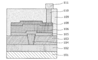
- FIG. 1A is a cross-sectional view of the gas sensor according to the first embodiment.
- FIG. 1B is a plan view of the gas sensor according to the first embodiment.
- FIG. 2A is a sectional view showing the method of manufacturing the gas sensor according to the first embodiment.
- FIG. 2B is a cross-sectional view showing the method of manufacturing the gas sensor according to the first embodiment.
- FIG. 2C is a cross-sectional view showing the method of manufacturing the gas sensor according to the first embodiment.
- FIG. 2D is a cross-sectional view showing the method of manufacturing the gas sensor according to the first embodiment.
- FIG. 2E is a cross-sectional view showing the method of manufacturing the gas sensor according to the first embodiment.
- FIG. 1A is a cross-sectional view of the gas sensor according to the first embodiment.
- FIG. 1B is a plan view of the gas sensor according to the first embodiment.
- FIG. 2A is a sectional view showing the method of manufacturing the gas sensor according to the first embodiment.
- FIG. 2F is a cross-sectional view showing the method of manufacturing the gas sensor according to the first embodiment.
- FIG. 2G is a cross-sectional view showing the method of manufacturing the gas sensor according to the first embodiment.
- FIG. 2H is a cross-sectional view showing the method of manufacturing the gas sensor according to the first embodiment.
- FIG. 2I is a cross-sectional view showing the method of manufacturing the gas sensor according to the first embodiment.
- FIG. 2J is a sectional view showing the method of manufacturing the gas sensor according to the first embodiment.
- FIG. 3 is a cross-sectional view of the gas sensor according to the first embodiment.
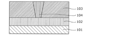
- FIG. 4 shows a method of forming a local region in the gas sensor according to the first embodiment.
- FIG. 5 is a diagram showing evaluation results of the gas sensor according to the first embodiment.
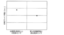
- FIG. 6 shows the evaluation results of the gas sensor without a step and the gas sensor according to the first embodiment.
- FIG. 7 shows the evaluation results of the gas sensor without a step and the gas sensor according to the first embodiment.
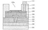
- FIG. 8A is a cross-sectional view of the gas sensor according to the second embodiment.
- FIG. 8B is a plan view of the gas sensor according to the second embodiment.
- FIG. 9A is a cross-sectional view showing the method of manufacturing the gas sensor according to the second embodiment.
- FIG. 9B is a sectional view showing the method of manufacturing the gas sensor according to the second embodiment.
- FIG. 9C is a sectional view showing the method of manufacturing the gas sensor according to the second embodiment.
- FIG. 9D is a cross-sectional view showing the method of manufacturing the gas sensor according to the second embodiment.
- FIG. 9E is a cross-sectional view showing the method of manufacturing the gas sensor according to the second embodiment.
- FIG. 9F is a cross-sectional view showing the method of manufacturing the gas sensor according to the second embodiment.
- FIG. 9G is a cross-sectional view showing the method of manufacturing the gas sensor according to the second embodiment.
- FIG. 9H is a cross-sectional view showing the method of manufacturing the gas sensor according to the second embodiment.
- FIG. 9I is a cross-sectional view showing the method of manufacturing the gas sensor according to the second embodiment.
- FIG. 9J is a cross-sectional view showing the method of manufacturing the gas sensor according to the second embodiment.
- FIG. 10 is a cross-sectional view of the gas sensor according to the second embodiment.
- FIG. 11 is a side view of the fuel cell vehicle according to the third embodiment.
- Patent Document 1 It is described that the gas sensor disclosed in Patent Document 1 can detect a combustible gas containing hydrogen, but there is no description regarding a detailed mechanism. Therefore, a phenomenon similar to the mechanism disclosed in Non-Patent Document 1 regarding a gas sensor (Pt—Ta 2 O 5 —Si) using a MIS (metal-insulating film-semiconductor) structure is also caused in Patent Document 1. Assuming that, the mechanism can be explained as follows.
- the MIM structure using an insulating film in which a predetermined amount of palladium and glass are added to tantalum pentoxide and platinum as the upper and lower metal electrodes sandwiching the insulating film is a gas that detects a gas having a hydrogen atom. It is considered to function as a sensor.
- a heater is provided adjacent to the gas detection element. At the time of measurement, a predetermined voltage is applied to the heater to raise the temperature of the gas detection element to 400 ° C. This is considered to increase the detection sensitivity of the gas detection element. That is, hydrogen atoms are dissociated by platinum, which is a metal having a catalytic action, but the rate at which hydrogen atoms are dissociated from molecules having a hydrogen atom by a catalytic action is proportional to the temperature rise, so the temperature of the gas detection element rises. It is considered that the detection sensitivity increases accordingly.
- a heater is installed adjacent to the gas detection element, and the ambient temperature is usually maintained at 100 ° C. or higher. Is being used.
- the gas sensor disclosed in the above-mentioned Non-Patent Document 1 using the MIS structure as a diode requires a temperature of 100 ° C. or higher for detection, and is disclosed in Non-Patent Document 2 using the MIS structure as a transistor.
- the operated gas sensor is operated at an ambient temperature of 115°C.
- Non-Patent Document 3 As a gas sensor utilizing the catalytic action of a metal, there is also a contact combustion type gas sensor disclosed in Non-Patent Document 3, but even in this contact combustion type, the gas detection element is operated from 200 ° C. to 300 ° C. during operation. It is heating.
- the gas detection element is 100 ° C. or higher. Is heated to.
- the gas detection element is heated to 100 ° C. or higher in order to improve the sensitivity for detecting a gas containing a hydrogen atom, and the minimum power consumption is about 100 mW. Therefore, when the gas detection element is used in the always ON state, there is a problem that the power consumption becomes very large.
- the gas sensor according to one aspect of the present disclosure can detect a gas molecule containing a hydrogen atom with high sensitivity and stability, and is excellent in power saving.
- the gas sensor according to one aspect of the present disclosure, the method for manufacturing the gas sensor, and the fuel cell vehicle have the following features.
- a gas sensor has a first electrode, a metal oxide layer formed on the first electrode, and a second electrode formed on the metal oxide layer, and is present in a gas. And a gas detecting element for detecting a gas molecule containing a hydrogen atom, and an opening exposing a part of the second electrode, and another one of the first electrode, the metal oxide layer and the second electrode.
- a first insulating film that covers a portion of the metal oxide layer, the metal oxide layer having a characteristic that its resistance value changes when the second electrode contacts the gas molecule.
- a first step is formed at a portion of the interface with the second electrode located within the opening in a plan view, and a local region is formed in the vicinity of the first step in the metal oxide layer. The oxygen deficiency in the local region is higher than the oxygen deficiency in regions other than the local region in the metal oxide layer.
- the first step may have an upward convex shape.
- a first contact plug is formed between the substrate and the first electrode, and the first contact plug has a side surface covered with a second insulating film.
- the upper surface of the first contact plug is formed so as to project from the upper surface of the second insulating film, and the first electrode is formed of the upper surface of the first contact plug and the second insulating film around the upper surface.
- a second step may be formed so as to extend over the upper surface, and the first step may be a step obtained by transferring the second step to the upper surface of the metal oxide layer.
- the first step may have a downward convex shape.
- a first contact plug is formed between the substrate and the first electrode, and the first contact plug has a second insulating film around the side surface thereof. It is covered, and the upper surface of the first contact plug is formed by being recessed from the upper surface of the second insulating film, and the first electrode is the upper surface of the first contact plug and the second insulating film around the upper surface.
- a third step formed over the upper surface of the metal oxide layer, and the first step may be a step formed by transferring the third step to the upper surface of the metal oxide layer.
- the second electrode may include a material having a catalytic action to dissociate the hydrogen atom from the gas molecule.
- the second electrode may include platinum or palladium.
- the metal oxide layer reversibly has a high resistance state and a low resistance state based on a voltage applied between the first electrode and the second electrode. You may transit between and.
- a current detection unit that detects a current flowing through the metal oxide layer when a predetermined voltage is applied between the first electrode and the second electrode is provided. Further, the decrease of the resistance value may be detected by the increase of the current detected by the current detection unit.
- the metal oxide layer may include a transition metal oxide.
- the transition metal oxide may be any of tantalum oxide, hafnium oxide, and zirconium oxide.
- the second contact plug connected to the second electrode through a part of the portion of the first insulating film covering the second electrode and the said. And a conductor connected to the second contact plug above the second contact plug.
- the method for manufacturing a gas sensor includes a step of forming a first electrode film on a substrate and a metal oxide film having a first step on the upper surface on the first electrode film. And a step of forming a second electrode film on the metal oxide film, and the first electrode film, the metal oxide film, and the second electrode film so as to include the first step in a plan view.
- the method for manufacturing a gas sensor includes a step of forming a second insulating film on the substrate, a step of forming a first contact plug in the second insulating film, and the first step.
- the step of removing the upper portion of the second insulating film around the contact plug and projecting the upper surface of the first contact plug from the upper surface of the surrounding second insulating film further includes the step of projecting the upper surface of the first contact plug.
- the first electrode film and the metal oxidation are sequentially formed on the first contact plug and the second insulating film so as to straddle the second step which is a step between the upper surface and the upper surface of the second insulating film around the upper surface.
- the material film and the second electrode film may be formed, and the gas detection element having the first step to which the second step is transferred may be formed.
- the method for manufacturing a gas sensor includes a step of forming a second insulating film on the substrate, a step of forming a first contact plug in the second insulating film, and the above.
- the step of removing the upper portion of the first contact plug and denting the upper surface of the first contact plug from the upper surface of the surrounding second insulating film further includes the step of removing the upper surface of the first contact plug and the surrounding surface thereof.
- the first electrode film, the metal oxide film, and the second film are sequentially formed on the first contact plug and the second insulating film so as to extend over a third step that is a step with the upper surface of the second insulating film.
- An electrode film may be formed to form the gas detection element having the first step to which the third step is transferred.
- the fuel cell vehicle includes a passenger compartment, a gas tank chamber in which a hydrogen gas tank is arranged, a fuel cell chamber in which a fuel cell is arranged, and a gas sensor according to any one of the above.
- the gas sensor is disposed in at least one of the gas tank chamber and the fuel cell chamber.
- the gas sensor according to the first embodiment is a gas sensor having a metal-insulating film-metal (MIM) structure in which a metal oxide layer as an insulating film and a metal film are stacked.
- the gas sensor can detect hydrogen-containing gas without heating with a heater by utilizing self-heating and gas sensitivity in a local region formed in the metal oxide layer.
- the hydrogen-containing gas is a general term for gases composed of molecules having hydrogen atoms, and may include hydrogen, methane, alcohol, and the like, as an example.
- FIG. 1A is a cross-sectional view showing a configuration example of the gas sensor 100 according to the present embodiment.
- FIG. 1B is a top view showing a configuration example of the gas sensor 100 according to the present embodiment.
- FIG. 1A corresponds to the cross section seen in the direction of the arrow in the cutting line of IA-IA'in FIG. 1B.
- the gas sensor 100 is connected to the first wiring 102 through the substrate 101, the first wiring 102, the second insulating film 103 arranged on the first wiring 102, and the second insulating film 103.
- a first insulating film 109 that covers at least a part of the oxide layer 106 and the second electrode 108, a second contact plug 110 that penetrates the first insulating film 109 and is connected to the second electrode 108, and a second contact plug.
- the second wiring 111 is formed on the first insulating film 109 so as to be connected to the first insulating film 109.
- the upper surface of the first contact plug 104 is formed at a position higher than the upper surface of the second insulating film 103, and the second step 122 is formed by the first contact plug 104 and the second insulating film 103 adjacent thereto. ing.
- the first electrode 105, the metal oxide layer 106, and the second electrode 108 are transferred so as to transfer the second step 122 formed by the first contact plug 104 and the second insulating film 103 adjacent thereto.
- a first step 121 is formed above the 1 contact plug 104.
- the first insulating film 109 has an opening 109 a formed on the second electrode 108 to expose the upper surface of the second electrode 108.
- the first step of the second electrode 108 that transfers the second step 122 formed by the first contact plug 104 and the second insulating film 103 adjacent thereto is on the bottom surface of the opening 109a. 121 is exposed.
- the first step 121 has an upward convex shape. It is not essential that the first step 121 is exposed on the upper surface of the second electrode 108, and the first step 121 has an opening 109a at the interface between the metal oxide layer 106 and the second electrode 108 in a plan view. It suffices if it is formed in a portion located inside.
- the metal oxide layer 106 is a layer whose resistance value reversibly changes based on an electric signal applied between the first electrode 105 and the second electrode 108.
- the metal oxide layer 106 is in a high resistance state depending on the voltage applied between the first electrode 105 and the second electrode 108 and the presence or absence of a hydrogen-containing gas in the gas with which the second electrode 108 is in contact. It makes a reversible transition to and from the low resistance state.
- the metal oxide layer 106 there is a local region 107 that is in contact with the second electrode 108 but not in contact with the first electrode 105.
- the local region 107 is a minute region including a filament composed of oxygen defect sites, and the filament functions as a conductive path.
- the metal oxide layer 106 is composed of a metal oxide, and the oxygen deficiency of the metal oxide contained in the local region 107 of the metal oxide layer 106 depends on the local region of the metal oxide layer 106. It is larger than the oxygen deficiency of the metal oxide contained in the portion other than 107.
- the oxygen deficiency of the metal oxide contained in the local region 107 depends on the voltage applied between the first electrode 105 and the second electrode 108 and the hydrogen content in the gas with which the second electrode 108 contacts through the opening 109a. It reversibly changes depending on the presence or absence of gas.
- the “oxygen deficiency” means the ratio of oxygen deficient to the amount of oxygen contained in the oxide of the stoichiometric composition in the metal oxide.
- the stoichiometric composition of the metal oxide in the present specification is a plurality of stoichiometric compositions. It means a stoichiometric composition with the highest resistance value in the composition.
- the metal oxide in the stoichiometric composition is more stable and has a higher resistance value than the metal oxides in the other stoichiometric composition states.
- the oxide of stoichiometric composition as defined above is Ta 2 O 5 .
- Ta 2 O 5 can also be expressed as Ta O 2.5 .
- the oxygen deficiency of TaO 2.5 is 0%.
- a metal oxide having a low oxygen deficiency is closer to a metal oxide having a stoichiometric composition and thus has a higher resistance value, and a metal oxide having a high oxygen deficiency is closer to a metal that is a component of the metal oxide The resistance is low.
- the "oxygen content” means the ratio of oxygen atoms to the total number of atoms.
- the oxygen content of Ta 2 O 5 is the ratio of oxygen atoms to the total number of atoms (O/(Ta+O)), which is 71.4 atm %. Therefore, the oxygen content of the oxygen-deficient tantalum oxide is greater than 0 and less than 71.4 atm%.
- the local region 107 is formed in the metal oxide layer 106 by applying an initial break voltage between the first electrode 105 and the second electrode 108.
- the initial break voltage is more absolute than a normal write voltage applied between the first electrode 105 and the second electrode 108 to reversibly transition the metal oxide layer 106 between a high resistance state and a low resistance state. It may be a voltage having a large value or a voltage having an absolute value smaller than the writing voltage. Further, the initial break voltage may be applied repeatedly or continuously for a predetermined time.
- a local region 107 that contacts the second electrode 108 but does not contact the first electrode 105 is formed in the metal oxide layer 106.
- the local region 107 is concentrated in the vicinity of the first step 121 of the metal oxide layer 106 to which the second step 122 formed between the first contact plug 104 and the second insulating film 103 is transferred. Generated.
- Local region 107 is considered to contain filaments composed of oxygen defective sites. Further, the size of the local region 107 is a minute size commensurate with the filament required for passing an electric current. The formation of filaments in the local region 107 is explained using a percolation model.
- the percolation model assumes a random distribution of oxygen defective sites (hereinafter simply referred to as defective sites) in the local region 107, and the probability that defective site connections are formed when the density of defective sites exceeds a certain threshold. Is a model based on the theory that
- the filament is composed of a plurality of defective sites connected in the local region 107. Further, according to the percolation model, the resistance change in the metal oxide layer 106 appears due to the generation and disappearance of defect sites in the local region 107.
- defect means that oxygen is missing from the stoichiometric composition in the metal oxide.
- density of defect sites corresponds to the degree of oxygen deficiency. That is, as the degree of oxygen deficiency increases, so does the density of defective sites.
- Only one local region 107 may be formed on the metal oxide layer 106 of the gas sensor 100.
- the number of local regions 107 in the metal oxide layer 106 can be confirmed by, for example, EBAC (Electron Beam Absorbed Current) analysis.
- the local region 107 By forming the local region 107 in the metal oxide layer 106, when a voltage is applied between the first electrode 105 and the second electrode 108, the current in the metal oxide layer 106 is concentrated in the local region 107. Flow to. Since the local region 107 is minute, for example, heat generation due to a current of about several tens of ⁇ A (that is, power consumption of less than 0.1 mW) when a voltage of about 1 V is applied to read the resistance value causes a considerable temperature rise. ..
- the second electrode 108 is made of a catalytic metal, for example, platinum, and the contact region of the second electrode 108 with the local region 107 is heated by the heat generated by the local region 107 to generate hydrogen atoms from the hydrogen-containing gas. Increase the efficiency of dissociation.
- the hydrogen atoms dissociated from the hydrogen-containing gas at the second electrode 108 are combined with the oxygen atoms in the local region 107, and the resistance value of the local region 107 is reduced. descend.
- the gas sensor 100 has a characteristic that the resistance value of the metal oxide layer 106 decreases when the second electrode 108 comes into contact with the hydrogen-containing gas by the above mechanism. Due to this characteristic, the gas to be inspected is brought into contact with the second electrode 108, and the resistance value between the first electrode 105 and the second electrode 108 is lowered to reduce the hydrogen-containing gas contained in the gas to be inspected. Can be detected.
- the hydrogen-containing gas comes into contact with the second electrode 108, so that the resistance value further decreases. Therefore, the hydrogen-containing gas can be detected by a gas sensor in which the local region 107 is in either a high resistance state or a low resistance state. However, in order to more clearly detect the decrease in the resistance value, a gas sensor in which the local region 107 is electrically set to a high resistance state may be used. ..
- the metal oxide layer 106 contains oxygen-deficient metal oxide.
- the base metal of the metal oxide includes transition metals such as tantalum, hafnium (Hf), titanium (Ti), zirconium (Zr), niobium (Nb), tungsten (W), nickel (Ni), and iron (Fe). , At least one may be selected from the group consisting of aluminum (Al).
- transition metals can have a plurality of oxidation states, different resistance states can be realized by a redox reaction.
- the oxygen-deficient metal oxide refers to a metal oxide having a smaller oxygen content (atomic ratio) than the composition of a metal oxide having a stoichiometric composition, which is usually an insulator. Many oxygen-deficient metal oxides usually behave like a semiconductor. By using the oxygen-deficient metal oxide for the metal oxide layer 106, it is possible to realize a highly reproducible and stable resistance change operation in the gas sensor 100.
- the resistance value of the metal oxide layer 106 is 1.6 or more when the composition is expressed as HfO x. Can be changed stably.
- the film thickness of the hafnium oxide may be 3 nm to 4 nm.
- the resistance value of the metal oxide layer 106 when x is 1.4 or more when the composition is expressed as ZrO x. Can be changed stably.
- the film thickness of the zirconium oxide may be 1 to 5 nm.
- the resistance value of the metal oxide layer 106 when x is 2.1 or more when the composition is expressed as TaO x. Can be changed stably.
- composition of each metal oxide layer shown above can be measured using the Rutherford backscattering method.
- the materials of the first electrode 105 and the second electrode 108 are, for example, platinum, iridium (Ir), palladium (Pd), silver (Ag), nickel, tungsten, copper (Cu), aluminum, tantalum, titanium, and nitride. It may be selected from titanium (TiN), tantalum nitride (TaN) and titanium aluminum nitride (TiAlN).
- the material of the second electrode 108 for example, a material having a catalytic action for dissociating a hydrogen atom from a gas molecule having a hydrogen atom such as platinum, iridium, and palladium may be used.
- a material having a lower standard electrode potential than the metal constituting the metal oxide such as tungsten, nickel, tantalum, titanium, aluminum, tantalum nitride, and titanium nitride, is used. Good.
- the higher the standard electrode potential the more difficult it is to oxidize.
- the substrate 101 for example, a silicon single crystal substrate or a semiconductor substrate can be used, but the substrate 101 is not limited thereto. Since the metal oxide layer 106 can be formed at a relatively low substrate temperature, for example, the metal oxide layer 106 can be formed on a resin material or the like.
- the gas sensor 100 may further include, for example, a fixed resistor, a transistor, or a diode as a load element electrically connected to the metal oxide layer 106.
- the gas sensor 100 may include a measurement circuit for measuring the current flowing through the metal oxide layer 106 when a predetermined voltage is applied between the first electrode 105 and the second electrode 108.
- the gas sensor 100 may include a power supply circuit that constantly applies a predetermined voltage between the first electrode 105 and the second electrode 108. According to such a configuration, a highly convenient gas sensor can be obtained as a module component including a measurement circuit or a power supply circuit.
- the wiring shape is patterned by a photolithography method, and then the aluminum is etched by a dry etching method to form the wiring shape.
- the first wiring 102 is formed by processing. At that time, for example, an insulating film formed by a CVD (Chemical Vapor Deposition) method may be sandwiched between the first wiring 102 and the silicon substrate 101. Further, the first wiring 102 may be copper in addition to aluminum, and adhesion layers such as titanium and titanium nitride may be formed above and below the aluminum.
- a silicon oxide film is deposited to a thickness of 500 nm on the first wiring 102 by, for example, a CVD method to form a second insulating film 103.
- the second insulating film 103 may have a laminated structure of a silicon oxide film and a silicon nitride film.
- a mask patterned into a hole shape is arranged on the second insulating film 103 by the photolithography method, and then the second insulating film 103 is penetrated by the dry etching method using the mask to reach the first wiring 102.
- Form holes (not shown).
- a tungsten film is formed on the entire surface of the 800 nm wafer by a CVD method, and a first contact plug film 104a is formed in the hole so as to be in contact with the first wiring 102.
- the first contact plug film 104a may be copper, or titanium, titanium nitride, tantalum, nitride may be provided between the first contact plug film 104a made of tungsten or copper and the first wiring 102 and the second insulating film 103. It is also possible to form an adhesion layer such as tantalum and a barrier layer.
- the first contact plug film 104a is polished by the CMP (Chemical Mechanical Polishing) method until the second insulating film 103 is exposed, and the first contact plug 104 is formed in the hole.
- CMP Chemical Mechanical Polishing
- the surface of the first contact plug film 104a is set to be at least as high as or lower than the surface of the surrounding second insulating film 103.
- the upper part of the second insulating film 103 is etched by, for example, 50 nm with a chemical solution containing hydrofluoric acid (HF) by a wet etching method, and the upper surface of the first contact plug 104 is subjected to the first contact plug. It is projected from the surface of the second insulating film 103 formed on the peripheral side surface of the 104. In this way, the second step 122 is formed at the boundary between the first contact plug 104 and the second insulating film 103.
- HF hydrofluoric acid
- the first electrode film 105a for example, a tantalum nitride film having a thickness of 30 nm is projected from the surfaces of the second insulating film 103 and the second insulating film 103 by a sputtering method. Is formed so as to cover the surface of. At that time, the first electrode film 105a may be a laminated film such as titanium or titanium nitride.
- a metal oxide film 106a having a thickness of 30 nm is formed on the first electrode film 105a by a reactive sputtering method using, for example, a Ta target.
- a platinum film having a thickness of 10 nm, for example, is formed as the second electrode film 108a on the metal oxide film 106a by a sputtering method.
- the thickness of the platinum film is preferably 5 nm or more and 200 nm or less.
- the first electrode film 105a, the metal oxide film 106a, and the second electrode film 108a Is transferred to the first electrode film 105a, the metal oxide film 106a, and the second electrode film 108a, and the first step 121 is formed near the boundary region between the first contact plug 104 and the second insulating film 103 in the second electrode film 108a. It becomes a structure to have.
- a first mask 112 by a photoresist is formed in a sensor shape on the second electrode film 108a including the first step 121 in a plan view, for example, by a photolithography method.
- the dimension of the first mask 112 in plan view may be, for example, about 1 ⁇ m square to 8 ⁇ m square.
- the first electrode film 105a, the metal oxide film 106a, and the second electrode film 108a are patterned into the shape of the gas detection element by dry etching using the first mask 112, and the first A gas detection element including the electrode 105, the metal oxide layer 106, and the second electrode 108 is formed.
- a silicon oxide film of, eg, 800 nm is formed as the first insulating film 109 so as to cover at least a part of the metal oxide layer 106 and the second electrode 108.
- the upper portion of the first insulating film 109 is polished to a thickness of 300 nm by the CMP method to flatten the surface of the first insulating film 109.
- a via hole is provided which penetrates the first insulating film 109 by etching and reaches a part of the second electrode 108, then a tungsten film is formed on the entire surface of an 800 nm wafer by a CVD method, and tungsten is deposited only in the plug by a CMP method.
- the second contact plug 110 is formed by flattening until it remains in the wafer. After that, a new conductor film is deposited on the first insulating film 109 and patterned to form a second wiring 111 connected to the second contact plug 110.
- a second mask 113 made of a photoresist is formed on the first insulating film 109 by a lithography method.
- the opening of the second mask 113 is formed inside the second electrode 108 and in a shape including the entire first step 121 formed in the second electrode 108.
- the first insulating film 109 is etched by a dry etching method using the second mask 113 to form an opening 109a that exposes a part of the surface of the second electrode 108.
- a local region 107 is formed in the metal oxide layer 106 by applying an initial break voltage between the first electrode 105 and the second electrode 108 in the gas sensor 100. Then, the gas sensor 100 is completed.
- the local region 107 is the first step 121 portion of the metal oxide layer 106 to which the second step 122 formed between the first contact plug 104 and the second insulating film 103 is transferred. That is, it is concentrated in the vicinity of the first step 121 formed on the second electrode 108.
- FIG. 4 is a measurement result showing an example of resistance change characteristics of the gas sensor 100 of the present embodiment due to voltage application.
- the sizes of the first electrode 105, the second electrode 108, and the metal oxide layer 106 are all 3 ⁇ m ⁇ 3 ⁇ m (area 9 ⁇ m 2 ).
- the initial break voltage (for example, 3V) is set to the first electrode 105 and the second electrode 108.
- the resistance value changes to the low resistance value LR by applying the voltage during the period (step S301).
- a writing voltage between the first electrode 105 and the second electrode 108 of the gas sensor 100 for example, two types of voltage pulses having a pulse width of 100 ns and different polarities, that is, a positive voltage pulse (for example, 2.5 V).
- a negative voltage pulse for example, 1.8 V
- the resistance value of the metal oxide layer 106 changes as shown in FIG.
- the resistance value of the metal oxide layer 106 increases from the low resistance value LR to the high resistance value HR (step S302).
- a negative voltage pulse is applied as a write voltage between the electrodes, the resistance value of the metal oxide layer 106 decreases from the high resistance value HR to the low resistance value LR (step S303).
- the polarity of the voltage pulse is “positive” when the potential of the second electrode 108 is high with respect to the potential of the first electrode 105, and the potential of the second electrode 108 is low with respect to the potential of the first electrode 105. The case is defined as "negative".
- a positive voltage pulse is finally applied between the first electrode 105 and the second electrode 108 before starting the monitoring of the hydrogen-containing gas.
- the gas sensor 100 is set in a high resistance state.
- the initial setting is made in this way, the decrease in the resistance value can be detected more clearly as compared with the case where the hydrogen-containing gas is detected by using the gas sensor 100 in the low resistance state as described above. Detection characteristics are improved.
- FIG. 5 is a graph showing an evaluation example of the gas sensor 100 of this embodiment.
- the horizontal axis represents time (au), and the vertical axis represents the current value (au) flowing between the first electrode 105 and the second electrode 108.
- nitrogen gas was first introduced into a closed container in which the gas sensor 100 was placed, then the nitrogen gas was switched to hydrogen gas, and then the hydrogen gas was further switched to nitrogen gas. Further, the gas sensor 100 in which the local region 107 is set to a high resistance state by applying a predetermined voltage in advance between the first electrode 105 and the second electrode 108 was used.
- FIG. 5 shows the evaluation results at this time, and the horizontal axis shows the three periods in which the first nitrogen introduction (step S501), the hydrogen introduction (step S502), and the subsequent nitrogen introduction (step S503) were performed. .. It can be seen that the current value begins to increase immediately after switching the introduction gas from nitrogen gas to hydrogen gas. In addition, it can be seen that the current begins to decrease immediately after switching the introduction gas from hydrogen gas to nitrogen gas.
- the hydrogen-containing gas monitoring operation when a detection voltage of 0.6 V is applied between the first electrode 105 and the second electrode 108, the first electrode 105 is in a state where hydrogen gas is detected. A current of 10 ⁇ A to 20 ⁇ A flowed between the second electrode 108 and the second electrode 108. That is, according to the gas sensor 100 of the present embodiment, it can be seen that the hydrogen-containing gas can be monitored with a very small power consumption of 0.006 mW to 0.012 mW.
- the inventors infer the hydrogen gas detection mechanism of the gas sensor 100 as follows.
- this hydrogen atom causes a reduction reaction of the metal oxide in the local region 107, and the oxygen in the local region 107 is combined with hydrogen to reduce the oxygen deficiency of the metal oxide contained in the local region 107.
- the filaments in the local region 107 are easily connected, and the resistance value of the local region 107 is reduced.
- the current flowing between the first electrode 105 and the second electrode 108 increases.
- the operation described above is not limited to the gas sensor 100 of the present embodiment, and it is considered that the gas sensor 100 of the present embodiment has substantially the same structure as the gas sensor 100 of the present embodiment and other gas sensors described later. ..
- the above-described operation is not limited to the case where the gas contacting the second electrode 108 is hydrogen gas, and it is considered that the same occurs when the gas is a hydrogen-containing gas such as methane or alcohol.
- FIG. 6 shows a gas sensor according to a comparative example (hereinafter referred to as a gas sensor having no step) formed by the same method as the gas sensor according to the present embodiment except that no step is formed and the gas sensor according to the present embodiment. It is a result of comparing the initial break voltage of the metal oxide layer 106 for the gas sensor.
- the gas sensor of this embodiment has a lower initial break voltage. This is because the step shape formed on the first contact plug 104 and the second insulating film 103 is also transferred to the first electrode 105, the metal oxide layer 106, and the second electrode 108, so that the electric field concentration is concentrated at the step portion. This is because the effective voltage applied to the metal oxide layer 106 increases due to the generation. Therefore, the local region 107 is selectively formed near the step portion.
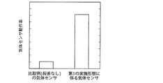
- FIG. 7 shows operation rates of the gas sensor having no step and the gas sensor formed in the present embodiment when the hydrogen concentration in the gas to be detected is set to 1%, for example.
- the operating rate of the gas sensor formed in the present embodiment is improved as compared with the operating rate of the gas sensor without steps.
- the gas sensor having no step has no step inside the sensor, and therefore the local region 107 is formed at random, and thus may be formed at a portion covered with the first insulating film 109, for example.
- hydrogen may not reach the local region 107, and does not operate as a gas sensor.
- the local region 107 is highly likely to be selectively formed at the stepped portion near the first contact plug 104, and the opening 109a is always formed in the first contact plug 104. Since it is formed so as to include immediately above, hydrogen can reach the local region 107 through the second electrode 108, so that the operating rate as a gas sensor is improved.
- the gas sensor 100 it is possible to stably detect the hydrogen-containing gas without the need to separately heat it with a heater, and thus a gas sensor excellent in power saving can be obtained.
- the gas sensor according to the second embodiment is a metal-insulation film-metal (MIM) formed by laminating a metal oxide layer as an insulation film and a metal film, like the gas sensor of the first embodiment described above. It is a gas sensor with a structure.
- the gas sensor can detect hydrogen-containing gas without heating with a heater by utilizing self-heating and gas sensitivity in a local region formed in a gas-sensitive resistance film.
- the hydrogen-containing gas is a general term for gases composed of molecules having hydrogen atoms, and may include hydrogen, methane, alcohol, and the like, as an example.
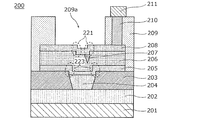
- FIG. 8A is a cross-sectional view showing a configuration example of the gas sensor 200 according to the present embodiment.
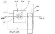
- FIG. 8B is a top view showing a configuration example of the gas sensor 200 according to the present embodiment.
- FIG. 8A corresponds to the cross section viewed in the direction of the arrow in the cutting line of VIIIA-VIIIA'of FIG. 8B.
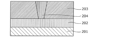
- the gas sensor 200 includes a substrate 201, a first wiring 202, a second insulating film 203 disposed on the first wiring 202, and a first wiring 202 penetrating the second insulating film 203 and connected to the first wiring 202.
- the upper surface of the first contact plug 204 is formed at a position lower than the upper surface of the second insulating film 203, and the third step 223 is formed by the first contact plug 204 and the second insulating film 203 adjacent thereto. ing.
- the first contact 205, the metal oxide layer 206, and the second electrode 208 are formed so that the third step 223 formed of the first contact plug 204 and the second insulating film 203 adjacent thereto is transferred.
- a first step 221 is formed above the one contact plug 204.
- the first insulating film 209 has an opening 209 a formed on the second electrode 208 to expose the upper surface of the second electrode 208.
- the first step of the second electrode 208 that transfers the third step 223 formed by the first contact plug 204 and the second insulating film 203 adjacent thereto on the bottom surface of the opening 209a. 221 is exposed.
- the first step 221 has a downward convex shape. It is not essential that the first step 221 is exposed on the upper surface of the second electrode 208, and the first step 221 has an opening 209a in a plan view of the interface between the metal oxide layer 206 and the second electrode 208. It suffices if it is formed in the portion located inside.
- the metal oxide layer 206 is a layer whose resistance value reversibly changes based on an electric signal applied between the first electrode 205 and the second electrode 208.
- the metal oxide layer 206 is in a high resistance state depending on the voltage applied between the first electrode 205 and the second electrode 208 and the presence or absence of a hydrogen-containing gas in the gas with which the second electrode 208 is in contact. It makes a reversible transition to and from the low resistance state.
- the metal oxide layer 206 there is a local region 207 that is in contact with the second electrode 208 but is not in contact with the first electrode 205.
- the local region 207 is a minute region containing a filament composed of oxygen-deficient sites, and the filament functions as a conductive path.
- the metal oxide layer 206 is composed of a metal oxide, and the oxygen deficiency of the metal oxide contained in the local region 207 of the metal oxide layer 206 is determined by the local region of the metal oxide layer 206. It is higher than the oxygen deficiency of the metal oxide contained in the portion other than 207.
- the oxygen deficiency of the metal oxide contained in the local region 207 depends on the voltage applied between the first electrode 205 and the second electrode 208 and the hydrogen content in the gas with which the second electrode 208 contacts through the opening 209a. It reversibly changes depending on the presence or absence of gas.
- the gas sensor 200 configured as described above has the following effects.
- a local region 207 that is in contact with the second electrode 208 but is not in contact with the first electrode 205 is formed in the metal oxide layer 206.
- the local region 207 is formed in the first portion of the metal oxide layer 206 to which the third step 223 formed between the first contact plug 204 and the second insulating film 203 is transferred. It is generated concentratedly in the vicinity of the first step 221.
- the mechanism of the resistance change phenomenon and the hydrogen detection in the gas sensor 200 is the same as the mechanism of the resistance change phenomenon and the hydrogen detection in the gas sensor 100 of the first embodiment, and thus the repeated description thereof will be omitted.
- the wiring shape is formed.
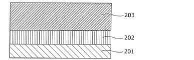
- the first wiring 202 is formed by processing. At that time, an insulating film may be sandwiched between the first wiring 202 and the silicon substrate 201, for example, by a CVD method. Further, the first wiring 202 may be copper instead of aluminum, and an adhesion layer of titanium, titanium nitride, or the like may be formed above and below aluminum.
- a silicon oxide film is deposited to a thickness of 500 nm on the first wiring 202 by, for example, a CVD method to form a second insulating film 203.
- the second insulating film 203 may have a laminated structure of a silicon oxide film and a silicon nitride film.
- a mask patterned into a hole shape is arranged on the second insulating film 203 by the photolithography method, and then the second insulating film 203 is penetrated by the dry etching method using the mask to reach the first wiring 202.
- Form holes (not shown).
- tungsten is formed on the entire surface of the 800 nm wafer by the CVD method, and the first contact plug film 204a is formed in the hole so as to be in contact with the first wiring 202.
- the first contact plug film 204a may be copper, or titanium, titanium nitride, tantalum, nitride may be provided between the first contact plug film 204a made of tungsten, copper, etc. and the first wiring 202 and the second insulating film 203. It is also possible to form an adhesion layer such as tantalum and a barrier layer.
- the first contact plug film 204a is polished by CMP until the second insulating film 203 is exposed to form the first contact plug 204 in the hole.
- the surface of the first contact plug film 204a is set to be at least as high as or lower than the surface of the surrounding second insulating film 203.
- W is etched by, for example, 30 nm by a dry etching method, and the upper surface of the first contact plug 204 is covered with the second insulating film 203 formed on the peripheral side surface of the first contact plug 204. It is formed so as to be lower than the surface.
- the third step 223 is formed at the boundary between the first contact plug 204 and the second insulating film 203, as in the gas sensor according to the first embodiment. The difference from the first embodiment is that the third step 223 is formed without etching the large-area second insulating film 203.
- the first electrode film 205a for example, a tantalum nitride film having a thickness of 30 nm is recessed from the surfaces of the second insulating film 203 and the second insulating film 203 by a sputtering method. Is formed so as to cover the surface of. At that time, the first electrode film 205a may be a laminated film of titanium, titanium nitride, or the like.
- a metal oxide film 206a having a thickness of 30 nm is formed on the first electrode film 205a by a reactive sputtering method using a tantalum target, for example.
- a platinum film having a thickness of 10 nm, for example, is formed as the second electrode film 208a on the metal oxide film 206a by a sputtering method.
- the thickness of the platinum film is preferably 5 nm or more and 200 nm or less.
- the third step 223 between the surface of the first contact plug 204 and the surface of the second insulating film 203 formed so as to be recessed below the surface of the surrounding second insulating film 203 is formed.
- a first mask 212 made of photoresist is formed in a sensor shape on the second electrode film 208a including the first step 221 in a plan view by, for example, photolithography.
- the dimensions of the first mask 212 may be, for example, about 1 ⁇ m square to 8 ⁇ m square.
- the first electrode film 205a, the metal oxide film 206a, and the second electrode film 208a are patterned into the shape of the gas detection element by dry etching using the first mask 212, and the first A gas sensing element including the electrode 205, the metal oxide layer 206, and the second electrode 208 is formed.
- the first insulating film 209 for example, an 800 nm silicon oxide film is formed so as to cover at least a part of the metal oxide layer 206 and the second electrode 208.
- the upper portion of the first insulating film 209 is polished by 300 nm by the CMP method to flatten the surface of the first insulating film 209.
- tungsten is formed on the entire surface of the 800 nm wafer by the CVD method, and the tungsten is formed only in the plug by the CMP method.
- the second contact plug 210 is formed by flattening until it remains. Then, a new conductor film is deposited on the first insulating film 209 and patterned to form the second wiring 211 connected to the second contact plug 210.
- a second mask 213 made of photoresist is formed on the first insulating film 209 by a lithography method.
- the opening of the second mask 213 is formed inside the second electrode 208 and in a shape including the entire first step 221 formed on the second electrode 208.
- the first insulating film 209 is etched by a dry etching method using the second mask 213 to form an opening 209a that exposes a part of the surface of the second electrode 208.
- an initial break voltage is applied between the first electrode 205 and the second electrode 208 in the gas sensor 200 to form a local region 207 in the metal oxide layer 206.
- the gas sensor 200 is completed.
- the local region 207 is the first step 221 portion of the metal oxide layer 206 to which the third step 223 formed between the first contact plug 204 and the second insulating film 203 is transferred. That is, it is concentrated in the vicinity of the first step 221 formed on the second electrode 108.
- the resistance change characteristic of the gas sensor 200 configured as described above due to voltage application is equivalent to the resistance change characteristic of the gas sensor 100 described with reference to FIGS. 4 and 5.
- the resistance change due to the hydrogen-containing gas of the gas sensor 200 occurs by the same mechanism as the mechanism described for the gas sensor 100.
- the gas sensor 200 it is not necessary to separately heat the gas with a heater, and hydrogen-containing gas can be stably detected, so that a gas sensor having excellent power saving can be obtained.
- the fuel cell vehicle according to the third embodiment includes any of the gas sensors described in the first and second embodiments described above and their modifications, and the gas sensor detects hydrogen gas in the vehicle. ..
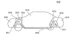
- FIG. 11 is a side view showing a configuration example of the fuel cell vehicle 800 according to the third embodiment.
- the fuel cell vehicle 800 includes a passenger compartment 810, a luggage compartment 820, a gas tank compartment 830, a fuel tank 831, a gas sensor 832, a pipe 840, a fuel cell compartment 850, a fuel cell 851, a gas sensor 852, a motor compartment 860, and a motor 861.
- the fuel tank 831 is provided in the gas tank chamber 830 and holds hydrogen gas as the fuel gas.
- the gas sensor 832 detects a fuel gas leak in the gas tank chamber 830.
- the fuel cell 851 includes a fuel cell stack in which a plurality of cells, which are basic units having a fuel electrode, an air electrode, and an electrolyte, are stacked.
- the fuel cell 851 is provided in the fuel cell chamber 850.
- the hydrogen gas in the fuel tank 831 is sent to the fuel cell 851 in the fuel cell chamber 850 through the pipe 840. Electric power is generated by reacting this hydrogen gas with oxygen gas in the atmosphere in the fuel cell 851.
- the gas sensor 852 detects hydrogen gas leakage in the fuel cell chamber 850.
- the motor 861 is provided in the motor chamber 860.
- the motor 861 is rotated by the electric power generated by the fuel cell 851 to drive the fuel cell vehicle 800.
- the gas sensor according to the present disclosure can detect a hydrogen-containing gas with a very small power consumption of about 0.01 mW, for example. Therefore, by utilizing the excellent power saving property of the gas sensor, it is possible to constantly monitor the hydrogen gas leakage without significantly increasing the standby power of the fuel cell vehicle.
- a predetermined voltage is constantly applied to the gas sensors 832 and 852, and the fuel tank in the gas tank chamber 830 is based on the amount of current flowing through the gas sensors 832 and 852. It may be determined whether or not hydrogen gas exists outside the fuel cell 851 in the fuel cell chamber 850 and outside the fuel cell chamber 850.
- the gas sensor is driven to determine the presence or absence of hydrogen gas leakage after the ignition key is operated.
- the starting time of the fuel cell vehicle can be shortened.
- safety can be improved by continuing to monitor the hydrogen gas leakage even after the fuel cell vehicle is running, for example, after the fuel cell vehicle is stored in the garage.
- the present embodiment includes various modifications that can be conceived by those skilled in the art, and a form constructed by combining the components of each embodiment within the scope of the present disclosure. is there.
- the gas sensor described above may further include a measuring circuit for measuring the current flowing through the metal oxide layer when a predetermined voltage is applied between the first electrode and the second electrode.
- the gas sensor described above may further include a power supply circuit that constantly applies a predetermined voltage between the first electrode and the second electrode.
- a highly convenient gas sensor can be obtained as a module component provided with a measurement circuit or a power supply circuit.
- the gas sensor according to the present disclosure functions as a gas sensor having excellent power saving properties, and is useful as a hydrogen sensor used in, for example, a fuel cell vehicle.
Landscapes
- Engineering & Computer Science (AREA)
- Life Sciences & Earth Sciences (AREA)
- Chemical & Material Sciences (AREA)
- Sustainable Energy (AREA)
- Sustainable Development (AREA)
- Health & Medical Sciences (AREA)
- Electrochemistry (AREA)
- Chemical Kinetics & Catalysis (AREA)
- Mechanical Engineering (AREA)
- Transportation (AREA)
- Immunology (AREA)
- General Physics & Mathematics (AREA)
- General Health & Medical Sciences (AREA)
- Pathology (AREA)
- Biochemistry (AREA)
- Analytical Chemistry (AREA)
- Physics & Mathematics (AREA)
- Power Engineering (AREA)
- Combustion & Propulsion (AREA)
- Manufacturing & Machinery (AREA)
- General Chemical & Material Sciences (AREA)
- Food Science & Technology (AREA)
- Medicinal Chemistry (AREA)
- Investigating Or Analyzing Materials By The Use Of Fluid Adsorption Or Reactions (AREA)
- Investigating Or Analyzing Materials By The Use Of Electric Means (AREA)
- Fuel Cell (AREA)
Priority Applications (3)
| Application Number | Priority Date | Filing Date | Title |
|---|---|---|---|
| JP2021503440A JP7433286B2 (ja) | 2019-03-07 | 2020-01-14 | 気体センサとその製造方法、および燃料電池自動車 |
| CN202080018278.5A CN113518917B (zh) | 2019-03-07 | 2020-01-14 | 气体传感器和其制造方法以及燃料电池汽车 |
| US17/459,262 US12235232B2 (en) | 2019-03-07 | 2021-08-27 | Gas sensor, method of manufacturing gas sensor, and fuel cell vehicle |
Applications Claiming Priority (2)
| Application Number | Priority Date | Filing Date | Title |
|---|---|---|---|
| JP2019-042012 | 2019-03-07 | ||
| JP2019042012 | 2019-03-07 |
Related Child Applications (1)
| Application Number | Title | Priority Date | Filing Date |
|---|---|---|---|
| US17/459,262 Continuation US12235232B2 (en) | 2019-03-07 | 2021-08-27 | Gas sensor, method of manufacturing gas sensor, and fuel cell vehicle |
Publications (1)
| Publication Number | Publication Date |
|---|---|
| WO2020179226A1 true WO2020179226A1 (ja) | 2020-09-10 |
Family
ID=72337869
Family Applications (1)
| Application Number | Title | Priority Date | Filing Date |
|---|---|---|---|
| PCT/JP2020/000803 Ceased WO2020179226A1 (ja) | 2019-03-07 | 2020-01-14 | 気体センサとその製造方法、および燃料電池自動車 |
Country Status (4)
| Country | Link |
|---|---|
| US (1) | US12235232B2 (https=) |
| JP (1) | JP7433286B2 (https=) |
| CN (1) | CN113518917B (https=) |
| WO (1) | WO2020179226A1 (https=) |
Cited By (4)
| Publication number | Priority date | Publication date | Assignee | Title |
|---|---|---|---|---|
| WO2021210453A1 (ja) * | 2020-04-16 | 2021-10-21 | ヌヴォトンテクノロジージャパン株式会社 | 水素センサ、水素検知方法および水素検知装置 |
| WO2023017748A1 (ja) * | 2021-08-11 | 2023-02-16 | ヌヴォトンテクノロジージャパン株式会社 | 水素センサ |
| WO2023136083A1 (ja) * | 2022-01-17 | 2023-07-20 | ヌヴォトンテクノロジージャパン株式会社 | 水素検知方法、駆動回路および水素検知装置 |
| WO2024053537A1 (ja) * | 2022-09-06 | 2024-03-14 | ヌヴォトンテクノロジージャパン株式会社 | 水素検知素子及びその製造方法 |
Families Citing this family (5)
| Publication number | Priority date | Publication date | Assignee | Title |
|---|---|---|---|---|
| US12546759B2 (en) | 2023-03-30 | 2026-02-10 | Saudi Arabian Oil Company | Thin polymer film dissolved under tension to detect hydrocarbon fuels hidden in paraffin-based lubrication oils |
| US12298266B2 (en) | 2023-03-30 | 2025-05-13 | Saudi Arabian Oil Company | Changes in resistivity of mesh-patterned polymer thin films coated with conductive traces used to detect hydrocarbon fuels hidden in paraffin-based lubrication oils |
| US12517107B2 (en) | 2023-04-11 | 2026-01-06 | Saudi Arabian Oil Company | Detecting hydrocarbon fuels in lubrication oils |
| US12392763B2 (en) | 2023-04-17 | 2025-08-19 | Saudi Arabian Oil Company | Hydrocarbon contaminant detection using polymer film |
| WO2025264179A1 (en) * | 2024-06-20 | 2025-12-26 | Agency For Science, Technology And Research | Hydrogen gas sensor and method of forming the same |
Citations (4)
| Publication number | Priority date | Publication date | Assignee | Title |
|---|---|---|---|---|
| JP2001509879A (ja) * | 1995-05-16 | 2001-07-24 | エレクトリック パワー リサーチ インスチテュート | 金属−絶縁膜−半導体センサによる流体の検出 |
| JP2013068567A (ja) * | 2011-09-26 | 2013-04-18 | Gunze Ltd | 水素ガスセンサの信号処理方法、及び信号処理装置 |
| JP2017173307A (ja) * | 2016-03-18 | 2017-09-28 | パナソニックIpマネジメント株式会社 | 水素センサ及び燃料電池自動車、並びに水素検出方法。 |
| WO2019044256A1 (ja) * | 2017-09-04 | 2019-03-07 | パナソニックIpマネジメント株式会社 | 気体センサ、気体検知装置、燃料電池自動車および気体センサの製造方法 |
Family Cites Families (17)
| Publication number | Priority date | Publication date | Assignee | Title |
|---|---|---|---|---|
| JPS5958348A (ja) | 1982-09-29 | 1984-04-04 | Hitachi Ltd | 水素ガス検知素子 |
| JP4590764B2 (ja) * | 2001-03-28 | 2010-12-01 | 株式会社デンソー | ガスセンサ及びその製造方法 |
| ES2212739B1 (es) * | 2003-01-02 | 2005-04-01 | Sociedad Española De Carburos Metalicos, S.A. | Sistema analizador para la deteccion de gases reductores y oxidantes en un gas portador y sensor de gases basado en oxidos metalicos de tipo semiconductor. |
| US20070054170A1 (en) * | 2005-09-02 | 2007-03-08 | Isenberg Arnold O | Oxygen ion conductors for electrochemical cells |
| US7951281B2 (en) * | 2008-06-04 | 2011-05-31 | Corning Incorporated | Methods for diminishing or preventing the deposition of a metal oxide on an electrode surface |
| JP5624866B2 (ja) * | 2010-12-06 | 2014-11-12 | ローム株式会社 | Memsセンサの製造方法 |
| JP5603193B2 (ja) * | 2010-09-29 | 2014-10-08 | 株式会社日立製作所 | ガスセンサ |
| JP5352032B2 (ja) | 2011-10-06 | 2013-11-27 | パナソニック株式会社 | 不揮発性記憶素子および不揮発性記憶装置 |
| US20130202489A1 (en) * | 2012-02-03 | 2013-08-08 | The Hong Kong Polytechnic University | Gas sensor with a highly porous structure constructed of catalyst-capped metal-oxide nanoclusters |
| JP6736351B2 (ja) * | 2015-06-19 | 2020-08-05 | 株式会社半導体エネルギー研究所 | 半導体装置 |
| EP3343212B1 (en) * | 2015-08-28 | 2019-11-06 | Panasonic Intellectual Property Management Co., Ltd. | Gas sensor and fuel cell vehicle |
| CN107102032B (zh) * | 2016-02-22 | 2021-08-06 | 新唐科技日本株式会社 | 气体传感器及氢浓度判定方法 |
| JP6738749B2 (ja) * | 2016-03-25 | 2020-08-12 | パナソニックセミコンダクターソリューションズ株式会社 | 気体センサ、水素検出方法、及び燃料電池自動車 |
| CN107315033B (zh) * | 2016-04-26 | 2021-08-06 | 新唐科技日本株式会社 | 气体检测装置以及氢检测方法 |
| CN107315034B (zh) * | 2016-04-26 | 2021-06-08 | 新唐科技日本株式会社 | 气体检测装置以及氢检测方法 |
| JP6873160B2 (ja) | 2016-12-28 | 2021-05-19 | ヌヴォトンテクノロジージャパン株式会社 | 気体検出装置、気体検出システム、燃料電池自動車、及び気体検出方法 |
| US11536677B2 (en) | 2016-12-28 | 2022-12-27 | Nuvoton Technology Corporation Japan | Gas detection device, gas sensor system, fuel cell vehicle, and hydrogen detection method |
-
2020
- 2020-01-14 JP JP2021503440A patent/JP7433286B2/ja active Active
- 2020-01-14 CN CN202080018278.5A patent/CN113518917B/zh active Active
- 2020-01-14 WO PCT/JP2020/000803 patent/WO2020179226A1/ja not_active Ceased
-
2021
- 2021-08-27 US US17/459,262 patent/US12235232B2/en active Active
Patent Citations (4)
| Publication number | Priority date | Publication date | Assignee | Title |
|---|---|---|---|---|
| JP2001509879A (ja) * | 1995-05-16 | 2001-07-24 | エレクトリック パワー リサーチ インスチテュート | 金属−絶縁膜−半導体センサによる流体の検出 |
| JP2013068567A (ja) * | 2011-09-26 | 2013-04-18 | Gunze Ltd | 水素ガスセンサの信号処理方法、及び信号処理装置 |
| JP2017173307A (ja) * | 2016-03-18 | 2017-09-28 | パナソニックIpマネジメント株式会社 | 水素センサ及び燃料電池自動車、並びに水素検出方法。 |
| WO2019044256A1 (ja) * | 2017-09-04 | 2019-03-07 | パナソニックIpマネジメント株式会社 | 気体センサ、気体検知装置、燃料電池自動車および気体センサの製造方法 |
Cited By (4)
| Publication number | Priority date | Publication date | Assignee | Title |
|---|---|---|---|---|
| WO2021210453A1 (ja) * | 2020-04-16 | 2021-10-21 | ヌヴォトンテクノロジージャパン株式会社 | 水素センサ、水素検知方法および水素検知装置 |
| WO2023017748A1 (ja) * | 2021-08-11 | 2023-02-16 | ヌヴォトンテクノロジージャパン株式会社 | 水素センサ |
| WO2023136083A1 (ja) * | 2022-01-17 | 2023-07-20 | ヌヴォトンテクノロジージャパン株式会社 | 水素検知方法、駆動回路および水素検知装置 |
| WO2024053537A1 (ja) * | 2022-09-06 | 2024-03-14 | ヌヴォトンテクノロジージャパン株式会社 | 水素検知素子及びその製造方法 |
Also Published As
| Publication number | Publication date |
|---|---|
| US12235232B2 (en) | 2025-02-25 |
| US20210389264A1 (en) | 2021-12-16 |
| JP7433286B2 (ja) | 2024-02-19 |
| CN113518917B (zh) | 2024-09-27 |
| JPWO2020179226A1 (https=) | 2020-09-10 |
| CN113518917A (zh) | 2021-10-19 |
Similar Documents
| Publication | Publication Date | Title |
|---|---|---|
| JP7433286B2 (ja) | 気体センサとその製造方法、および燃料電池自動車 | |
| JP6145762B1 (ja) | 気体センサ、及び燃料電池自動車 | |
| US10591432B2 (en) | Hydrogen detection method using gas sensor having a metal oxide layer | |
| JP6761764B2 (ja) | 水素センサ及び燃料電池自動車、並びに水素検出方法 | |
| JP6740159B2 (ja) | 気体検出装置及び気体検出方法 | |
| JP7027340B2 (ja) | 気体センサ、気体検知装置、燃料電池自動車および気体センサの製造方法 | |
| JP6886304B2 (ja) | 気体センサ | |
| JP6865234B2 (ja) | 気体検出装置、気体センサシステム、燃料電池自動車、及び水素検出方法 |
Legal Events
| Date | Code | Title | Description |
|---|---|---|---|
| 121 | Ep: the epo has been informed by wipo that ep was designated in this application |
Ref document number: 20765576 Country of ref document: EP Kind code of ref document: A1 |
|
| ENP | Entry into the national phase |
Ref document number: 2021503440 Country of ref document: JP Kind code of ref document: A |
|
| NENP | Non-entry into the national phase |
Ref country code: DE |
|
| 122 | Ep: pct application non-entry in european phase |
Ref document number: 20765576 Country of ref document: EP Kind code of ref document: A1 |