WO2020165952A1 - Dispositif radar, procédé de détection d'objet à observer, et dispositif embarqué - Google Patents
Dispositif radar, procédé de détection d'objet à observer, et dispositif embarqué Download PDFInfo
- Publication number
- WO2020165952A1 WO2020165952A1 PCT/JP2019/004877 JP2019004877W WO2020165952A1 WO 2020165952 A1 WO2020165952 A1 WO 2020165952A1 JP 2019004877 W JP2019004877 W JP 2019004877W WO 2020165952 A1 WO2020165952 A1 WO 2020165952A1
- Authority
- WO
- WIPO (PCT)
- Prior art keywords
- frequency
- unit
- electromagnetic noise
- radar signal
- radar
- Prior art date
Links
Images


Classifications
-
- G—PHYSICS
- G01—MEASURING; TESTING
- G01S—RADIO DIRECTION-FINDING; RADIO NAVIGATION; DETERMINING DISTANCE OR VELOCITY BY USE OF RADIO WAVES; LOCATING OR PRESENCE-DETECTING BY USE OF THE REFLECTION OR RERADIATION OF RADIO WAVES; ANALOGOUS ARRANGEMENTS USING OTHER WAVES
- G01S7/00—Details of systems according to groups G01S13/00, G01S15/00, G01S17/00
- G01S7/02—Details of systems according to groups G01S13/00, G01S15/00, G01S17/00 of systems according to group G01S13/00
- G01S7/35—Details of non-pulse systems
- G01S7/352—Receivers
- G01S7/354—Extracting wanted echo-signals
-
- G—PHYSICS
- G01—MEASURING; TESTING
- G01S—RADIO DIRECTION-FINDING; RADIO NAVIGATION; DETERMINING DISTANCE OR VELOCITY BY USE OF RADIO WAVES; LOCATING OR PRESENCE-DETECTING BY USE OF THE REFLECTION OR RERADIATION OF RADIO WAVES; ANALOGOUS ARRANGEMENTS USING OTHER WAVES
- G01S13/00—Systems using the reflection or reradiation of radio waves, e.g. radar systems; Analogous systems using reflection or reradiation of waves whose nature or wavelength is irrelevant or unspecified
- G01S13/88—Radar or analogous systems specially adapted for specific applications
- G01S13/93—Radar or analogous systems specially adapted for specific applications for anti-collision purposes
- G01S13/931—Radar or analogous systems specially adapted for specific applications for anti-collision purposes of land vehicles
-
- G—PHYSICS
- G01—MEASURING; TESTING
- G01S—RADIO DIRECTION-FINDING; RADIO NAVIGATION; DETERMINING DISTANCE OR VELOCITY BY USE OF RADIO WAVES; LOCATING OR PRESENCE-DETECTING BY USE OF THE REFLECTION OR RERADIATION OF RADIO WAVES; ANALOGOUS ARRANGEMENTS USING OTHER WAVES
- G01S7/00—Details of systems according to groups G01S13/00, G01S15/00, G01S17/00
- G01S7/02—Details of systems according to groups G01S13/00, G01S15/00, G01S17/00 of systems according to group G01S13/00
- G01S7/40—Means for monitoring or calibrating
- G01S7/4052—Means for monitoring or calibrating by simulation of echoes
- G01S7/4056—Means for monitoring or calibrating by simulation of echoes specially adapted to FMCW
-
- G—PHYSICS
- G01—MEASURING; TESTING
- G01S—RADIO DIRECTION-FINDING; RADIO NAVIGATION; DETERMINING DISTANCE OR VELOCITY BY USE OF RADIO WAVES; LOCATING OR PRESENCE-DETECTING BY USE OF THE REFLECTION OR RERADIATION OF RADIO WAVES; ANALOGOUS ARRANGEMENTS USING OTHER WAVES
- G01S13/00—Systems using the reflection or reradiation of radio waves, e.g. radar systems; Analogous systems using reflection or reradiation of waves whose nature or wavelength is irrelevant or unspecified
- G01S13/88—Radar or analogous systems specially adapted for specific applications
- G01S13/93—Radar or analogous systems specially adapted for specific applications for anti-collision purposes
- G01S13/931—Radar or analogous systems specially adapted for specific applications for anti-collision purposes of land vehicles
- G01S2013/9318—Controlling the steering
-
- G—PHYSICS
- G01—MEASURING; TESTING
- G01S—RADIO DIRECTION-FINDING; RADIO NAVIGATION; DETERMINING DISTANCE OR VELOCITY BY USE OF RADIO WAVES; LOCATING OR PRESENCE-DETECTING BY USE OF THE REFLECTION OR RERADIATION OF RADIO WAVES; ANALOGOUS ARRANGEMENTS USING OTHER WAVES
- G01S13/00—Systems using the reflection or reradiation of radio waves, e.g. radar systems; Analogous systems using reflection or reradiation of waves whose nature or wavelength is irrelevant or unspecified
- G01S13/88—Radar or analogous systems specially adapted for specific applications
- G01S13/93—Radar or analogous systems specially adapted for specific applications for anti-collision purposes
- G01S13/931—Radar or analogous systems specially adapted for specific applications for anti-collision purposes of land vehicles
- G01S2013/93185—Controlling the brakes
-
- G—PHYSICS
- G01—MEASURING; TESTING
- G01S—RADIO DIRECTION-FINDING; RADIO NAVIGATION; DETERMINING DISTANCE OR VELOCITY BY USE OF RADIO WAVES; LOCATING OR PRESENCE-DETECTING BY USE OF THE REFLECTION OR RERADIATION OF RADIO WAVES; ANALOGOUS ARRANGEMENTS USING OTHER WAVES
- G01S13/00—Systems using the reflection or reradiation of radio waves, e.g. radar systems; Analogous systems using reflection or reradiation of waves whose nature or wavelength is irrelevant or unspecified
- G01S13/88—Radar or analogous systems specially adapted for specific applications
- G01S13/93—Radar or analogous systems specially adapted for specific applications for anti-collision purposes
- G01S13/931—Radar or analogous systems specially adapted for specific applications for anti-collision purposes of land vehicles
- G01S2013/932—Radar or analogous systems specially adapted for specific applications for anti-collision purposes of land vehicles using own vehicle data, e.g. ground speed, steering wheel direction
Definitions
- the present invention relates to a radar device that detects an observation target, an observation target detection method, and an in-vehicle device.
- Patent Document 1 discloses an FMCW (Frequency Modulated Continuous Wave) type radar device.
- the radar device disclosed in Patent Document 1 divides an FM (Frequency Modulated) signal into a transmission signal and a local signal, transmits the transmission signal as an electromagnetic wave, and receives the electromagnetic wave reflected by a target as a reflected wave. To do.
- the radar device disclosed in Patent Document 1 measures a distance to a target from a spectrum of a beat signal obtained by mixing a received signal of a reflected wave and a local signal.
- the radar device disclosed in Patent Document 1 prevents false detection of a target even when receiving an external radio wave such as a transmission signal transmitted from another radar device mounted on an oncoming vehicle, and The following processing is performed in order to measure the distance to the target.
- the radar device disclosed in Patent Document 1 switches between a transmission mode in which a transmission signal is transmitted and a reception mode in which external radio waves are received without transmitting the transmission signal, and a beat signal obtained in the reception mode is detected.
- Store spectrum in memory Store spectrum in memory.
- the radar device disclosed in Patent Document 1 eliminates interference of external radio waves by correcting the spectrum of the beat signal obtained in the transmission mode based on the spectrum of the beat signal obtained in the reception mode stored in the memory. Therefore, false detection of the target is prevented.
- a mixer In the radar device disclosed in Patent Document 1, a mixer generates a beat signal by mixing a received signal and a local signal, and an AD (Analog to Digital) converter converts the beat signal generated by the mixer. Converted to digital signal.
- an AD converter converts the beat signal generated by the mixer into a digital signal
- electromagnetic noise at a sampling frequency of the AD converter or lower may be input, for example.
- the electromagnetic noise may be an electromagnetic wave generated from any part of the radar device or an electromagnetic wave coming from the outside of the radar device.
- the electromagnetic noise is input to the AD converter, the electromagnetic noise is superimposed on the beat signal. Therefore, it is only necessary to correct the spectrum of the beat signal obtained in the transmission mode based on the spectrum of the beat signal obtained in the reception mode.
- the detection accuracy of the target may deteriorate.
- the present invention has been made to solve the above problems, and a radar that can suppress deterioration in detection accuracy of an observation target even when electromagnetic noise is input to a conversion unit that converts a beat signal into digital data.
- An object is to obtain an apparatus, an observation target detection method, and an in-vehicle device.
- the radar device is a radar signal reflected by an observation target during a period in which a frequency-modulated signal whose frequency changes with the passage of time is intermittently and repeatedly transmitted as a radar signal, and the radar signal is being transmitted.
- a beat signal generation unit that generates a beat signal having a frequency that is the difference between the frequency of the transmitted radar signal and the frequency of the reflected wave, and the beat signal that is generated by the beat signal generation unit
- the electromagnetic wave input to the conversion unit using digital data output from the conversion unit and digital data output from the conversion unit during a period in which a radar signal is not transmitted.
- the electromagnetic noise detection unit that detects noise, the digital data output from the conversion unit, digital data during the period when the radar signal is being transmitted, and using the electromagnetic noise detected by the electromagnetic noise detection unit.
- the electromagnetic noise detection unit that detects the electromagnetic noise input to the conversion unit, Of the digital data output from the conversion unit, digital data during the period when the radar signal is being transmitted, and the electromagnetic noise detected by the electromagnetic noise detection unit, using an observation target detection unit that detects an observation target,
- the radar device is configured so as to include. Therefore, the radar device according to the present invention can suppress deterioration of the detection accuracy of the observation target even if electromagnetic noise is input to the conversion unit.
- FIG. 1 is a configuration diagram showing a radar device according to a first embodiment.
- 3 is a hardware configuration diagram showing hardware of a signal processing unit 12 in the radar device according to the first embodiment.
- FIG. It is a hardware block diagram of a computer in case the signal processing part 12 is implement
- 7 is a flowchart showing an observation target detection method which is a processing procedure of the signal processing unit 12.
- 3 is a configuration diagram showing an electromagnetic noise detection unit 13 of the signal processing unit 12.
- FIG. 3 is a configuration diagram showing a frequency calculation unit 15 of the signal processing unit 12.
- FIG. 7 is a flowchart showing a calculation process of a beat frequency and a Doppler frequency in the frequency calculation unit 15.
- 7 is an explanatory diagram showing a calculation process of a beat frequency and a Doppler frequency in the frequency calculation unit 15.
- FIG. 6 is a flowchart showing a process of calculating a frequency of electromagnetic noise and a Doppler frequency in the electromagnetic noise detector 13.
- 6 is an explanatory diagram showing a process of calculating a frequency of electromagnetic noise and a Doppler frequency in the electromagnetic noise detection unit 13.
- FIG. 5 is a configuration diagram showing a radar device according to a second embodiment.
- FIG. 9 is a configuration diagram showing another radar device according to the second embodiment.
- FIG. 7 is a configuration diagram showing a radar device according to a third embodiment. 4 is a configuration diagram showing an electromagnetic noise detection unit 71 of the signal processing unit 12.
- FIG. 7 is a configuration diagram showing a radar device according to a fourth embodiment. It is a block diagram which shows the vehicle-mounted apparatus which concerns on Embodiment 5.
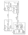
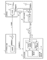
- FIG. 1 is a configuration diagram showing a radar device according to the first embodiment.
- FIG. 2 is a hardware configuration diagram showing the hardware of the signal processing unit 12 in the radar device according to the first embodiment.
- the radar signal output unit 1 includes a control unit 2 and a signal source 3.
- the radar signal output unit 1 outputs a frequency-modulated signal whose frequency changes with time as a radar signal intermittently and repeatedly to the transmitting/receiving unit 4.
- the control unit 2 outputs a control signal indicating the output timing of the radar signal to each of the signal source 3 and the signal processing unit 12.
- the signal source 3 intermittently repeatedly outputs the frequency-modulated signal as a radar signal to the distributor 5 according to the output timing indicated by the control signal output from the controller 2.
- the transmitter/receiver 4 includes a distributor 5, a transmitting antenna 6, and a receiving antenna 7.
- the transmission/reception unit 4 transmits the radar signal output from the radar signal output unit 1 toward the observation target, and receives the radar signal reflected by the observation target as a reflected wave.
- the transmission/reception unit 4 outputs the radar signal and the reflected wave output from the radar signal output unit 1 to the beat signal generation unit 8.
- the distributing unit 5 distributes the radar signal output from the signal source 3 into two, outputs one of the distributed radar signals to the transmitting antenna 6, and mixes the other radar signal as a local oscillation signal for frequency mixing. Output to the unit 9.
- the transmission antenna 6 radiates the radar signal output from the distribution unit 5 into space.
- the receiving antenna 7 receives the radar signal reflected by the observation target as a reflected wave after the radar signal is radiated into space from the transmitting antenna 6, and outputs the received signal of the received reflected wave to the frequency mixing unit 9.
- the beat signal generation unit 8 includes a frequency mixing unit 9 and a filter unit 10.
- the beat signal generation unit 8 transmits the radar signal transmitted from the transmission antenna 6.
- a beat signal having a frequency that is a difference between the frequency of the signal and the frequency of the reflected wave is generated.
- the beat signal generation unit 8 outputs the generated beat signal to a conversion unit (hereinafter referred to as “ADC (Analog to Digital Converter)”) 11.
- ADC Analog to Digital Converter
- the frequency mixing unit 9 mixes the local oscillation signal with the reception signal output from the receiving antenna 7 during a period in which the local oscillation signal is output from the distribution unit 5 to generate the local oscillation output from the distribution unit 5.
- a beat signal having a frequency that is a difference between the frequency of the signal and the frequency of the reflected wave is generated.
- the frequency mixing unit 9 outputs the generated beat signal to the filter unit 10.
- the filter unit 10 is realized by an LPF (Low Pass Filter), a BPF (Band Pass Filter), or the like.
- the filter unit 10 suppresses unnecessary components such as spurious contained in the beat signal output from the frequency mixing unit 9, and outputs the beat signal after suppressing unnecessary components to the ADC 11.
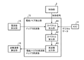
- the ADC 11 converts the beat signal generated by the beat signal generation unit 8 into digital data and outputs the digital data to the electromagnetic noise detection unit 13 and the observation target detection unit 14, respectively.
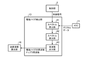
- the signal processing unit 12 includes an electromagnetic noise detection unit 13 and an observation target detection unit 14.
- the electromagnetic noise detection unit 13 is realized by, for example, the electromagnetic noise detection circuit 21 shown in FIG.
- the electromagnetic noise detection unit 13 refers to the control signal output from the control unit 2, and determines the period in which the radar signal is not output from the radar signal output unit 1 as the period in which the radar signal is not transmitted from the transmission/reception unit 4. Identify.
- the electromagnetic noise detection unit 13 detects the electromagnetic noise input to the ADC 11 by using the digital data during the specified period of the digital data output from the ADC 11. Specifically, the electromagnetic noise detection unit 13 uses the digital data during the specified period to determine the frequency of the electromagnetic noise input to the ADC 11 and the Doppler frequency corresponding to the relative speed with the source of the electromagnetic noise. calculate.
- the electromagnetic noise detection unit 13 outputs each of the electromagnetic noise frequency and the Doppler frequency to the distance velocity calculation unit 16.
- the observation target detection unit 14 includes a frequency calculation unit 15 and a distance/speed calculation unit 16.
- the observation target detection unit 14 refers to the control signal output from the control unit 2 and determines the period during which the radar signal is output from the radar signal output unit 1 as the period during which the radar signal is transmitted from the transmission/reception unit 4. Identify.
- the observation target detection unit 14 detects the observation target using the digital data during the specified period of the digital data output from the ADC 11 and the electromagnetic noise detected by the electromagnetic noise detection unit 13.
- the frequency calculation unit 15 is realized by, for example, the frequency calculation circuit 22 shown in FIG.
- the frequency calculation unit 15 refers to the control signal output from the control unit 2 and identifies the period during which the radar signal is output from the radar signal output unit 1.
- the frequency calculation unit 15 uses the digital data output from the ADC 11 during the specified period to calculate the beat frequency corresponding to the distance to the observation target and the Doppler frequency corresponding to the relative velocity with the observation target. Calculate each.
- the frequency calculation unit 15 outputs the beat frequency corresponding to the distance to the observation target and the Doppler frequency corresponding to the relative speed to the observation target to the distance/speed calculation unit 16.
- the distance speed calculation unit 16 is realized by, for example, the distance speed calculation circuit 23 shown in FIG.
- the distance velocity calculation unit 16 uses the electromagnetic noise frequency and Doppler frequency calculated by the electromagnetic noise detection unit 13 and the beat frequency and Doppler frequency calculated by the frequency calculation unit 15 to measure the distance to the observation target and the observation. Calculate each relative velocity with the target.
- each of the electromagnetic noise detection unit 13, the frequency calculation unit 15, and the distance/speed calculation unit 16, which are the constituent elements of the signal processing unit 12, are realized by dedicated hardware as shown in FIG. doing. That is, it is assumed that the signal processing unit 12 is realized by the electromagnetic noise detection circuit 21, the frequency calculation circuit 22, and the distance/speed calculation circuit 23.
- each of the electromagnetic noise detection circuit 21, the frequency calculation circuit 22, and the distance speed calculation circuit 23 is, for example, a single circuit, a composite circuit, a programmed processor, a parallel programmed processor, or an ASIC (Application Specific Integrated Circuit). , FPGA (Field-Programmable Gate Array), or a combination thereof.
- the constituent elements of the signal processing unit 12 are not limited to those realized by dedicated hardware, and the signal processing unit 12 may be realized by software, firmware, or a combination of software and firmware. Good.
- the software or firmware is stored in the memory of the computer as a program.
- the computer means hardware that executes a program, and corresponds to, for example, a CPU (Central Processing Unit), a central processing unit, a processing unit, an arithmetic unit, a microprocessor, a microcomputer, a processor, or a DSP (Digital Signal Processor).
- FIG. 3 is a hardware configuration diagram of a computer when the signal processing unit 12 is realized by software, firmware, or the like.
- FIG. 4 is a flowchart showing an observation target detection method which is a processing procedure of the signal processing unit 12.
- FIG. 2 shows an example in which each of the components of the signal processing unit 12 is realized by dedicated hardware
- FIG. 3 shows an example in which the signal processing unit 12 is realized by software or firmware. ..
- this is merely an example, and some of the constituent elements in the signal processing unit 12 may be realized by dedicated hardware and the remaining constituent elements may be realized by software or firmware.
- FIG. 5 is a configuration diagram showing the electromagnetic noise detection unit 13 of the signal processing unit 12.
- the spectrum calculation unit 41 refers to the control signal output from the control unit 2 to specify the period during which the radar signal output unit 1 does not output the radar signal.
- the spectrum calculation unit 41 calculates the first frequency spectrum related to the electromagnetic noise by Fourier-transforming the digital data in the specified period, out of the digital data output from the ADC 11, in the distance direction. Since the ADC 11 repeatedly outputs the digital data during the specified period from the ADC 11, the spectrum calculating unit 41 performs Fourier transform in the distance direction on each of the repeatedly output digital data to thereby obtain a plurality of electromagnetic noise-related first noises.
- the frequency spectrum of 1 is calculated.
- the spectrum calculation unit 41 outputs the plurality of calculated first frequency spectra related to the electromagnetic noise to the spectrum calculation unit 42.
- the spectrum calculation unit 42 acquires the plurality of first frequency spectra output from the spectrum calculation unit 41.
- the spectrum calculation unit 42 calculates the second frequency spectrum related to the electromagnetic noise by Fourier-transforming the acquired plurality of first frequency spectra in the relative velocity direction.
- the spectrum calculation unit 42 outputs the second frequency spectrum related to electromagnetic noise to the frequency output unit 43.
- the frequency output unit 43 detects the peak value of the spectrum value in the second frequency spectrum output from the spectrum calculation unit 42.
- the frequency output unit 43 outputs the beat frequency of the detected peak value to the distance/speed calculation unit 16 as the frequency of electromagnetic noise.
- the frequency output unit 43 outputs the detected Doppler frequency of the peak value to the distance/speed calculation unit 16 as the Doppler frequency corresponding to the relative speed with respect to the electromagnetic noise generation source.
- FIG. 6 is a configuration diagram showing the frequency calculation unit 15 of the signal processing unit 12.
- the spectrum calculation unit 51 refers to the control signal output from the control unit 2 and identifies the period during which the radar signal output unit 1 outputs the radar signal.
- the spectrum calculation unit 51 calculates the first frequency spectrum related to the observation target by performing Fourier transform in the distance direction on the digital data during the specified period, out of the digital data output from the ADC 11. Since the ADC 11 repeatedly outputs the digital data in the specified period from the ADC 11, the spectrum calculating unit 51 performs Fourier transform in the distance direction on each of the repeatedly output digital data to thereby obtain a plurality of first observation target data.
- the frequency spectrum of 1 is calculated.
- the spectrum calculation unit 51 outputs the plurality of calculated first frequency spectra of the observation target to the spectrum calculation unit 52.
- the spectrum calculation unit 52 acquires the plurality of first frequency spectra output from the spectrum calculation unit 51.
- the spectrum calculation unit 52 calculates the second frequency spectrum related to the observation target by Fourier-transforming the acquired plurality of first frequency spectra in the relative velocity direction.
- the spectrum calculation unit 52 outputs the second frequency spectrum related to the observation target to the frequency output unit 53.
- the frequency output unit 53 detects the peak value of the spectrum value in the second frequency spectrum output from the spectrum calculation unit 52.
- the frequency output unit 53 outputs the beat frequency of the detected peak value to the distance speed calculation unit 16 as a beat frequency corresponding to the distance to the observation target.
- the frequency output unit 53 outputs the Doppler frequency of the detected peak value to the distance/velocity calculation unit 16 as the Doppler frequency corresponding to the relative velocity with the observation target.
- FIG. 7 is an explanatory diagram showing an example of measurement timing of an observation target in the radar device shown in FIG.
- the control unit 2 outputs a control signal indicating the output timing of the radar signal to each of the signal source 3 and the signal processing unit 12.
- a period in which the control signal is ON is a period in which the radar signal is output, and a period in which the control signal is OFF is a period in which the radar signal is not output.
- the control signal is turned ON for K times. Further, the period in which the control signal is turned on and then turned off is K times.
- the signal source 3 outputs the frequency-modulated signal to the distributor 5 as a radar signal during the period when the control signal output from the controller 2 is ON. As shown in FIG. 7, the signal source 3 does not output the radar signal to the distributor 5 during the period in which the control signal output from the controller 2 is OFF.
- the distributor 5 distributes the radar signal output from the signal source 3 into two.
- the distributing unit 5 outputs one of the distributed radar signals to the transmitting antenna 6, and outputs the other distributed radar signal to the frequency mixing unit 9 as a local oscillation signal.
- the transmission antenna 6 radiates the radar signal into space.
- the receiving antenna 7 receives the radar signal reflected by the observation target as a reflected wave after the radar signal is radiated into space from the transmitting antenna 6, and outputs the received signal of the received reflected wave to the frequency mixing unit 9.
- the frequency mixing unit 9 mixes the local oscillation signal and the reception signal output from the reception antenna 7 to generate a radar signal output from the distribution unit 5.
- a beat signal having a frequency that is the difference between the frequency and the frequency of the reflected wave is generated.
- the frequency mixing unit 9 outputs the generated beat signal to the filter unit 10.
- the filter unit 10 suppresses unnecessary components such as spurious contained in the beat signal, and outputs the beat signal after suppressing the unnecessary component to the ADC 11.
- the ADC 11 Upon receiving the beat signal from the filter unit 10, the ADC 11 converts the beat signal into digital data and outputs the digital data to the electromagnetic noise detection unit 13 and the frequency calculation unit 15. For example, electromagnetic noise below the sampling frequency band of the ADC 11 may be input to the ADC 11, and the electromagnetic noise may be superimposed on the beat signal.
- the electromagnetic noise may be an electromagnetic wave generated from any part of the radar device or an electromagnetic wave coming from the outside of the radar device.
- the ADC 11 converts the input electromagnetic noise into digital data and outputs the digital data to the electromagnetic noise detection unit 13 and the frequency calculation unit 15.
- the frequency calculation unit 15 refers to the control signal output from the control unit 2 and identifies the period during which the radar signal is output from the radar signal output unit 1. In FIG. 7, the period when the radar signal is ON is the period when the radar signal is output from the radar signal output unit 1.
- the frequency calculation unit 15 uses the digital data output from the ADC 11 during the specified period to calculate the beat frequency corresponding to the distance to the observation target and the Doppler frequency corresponding to the relative velocity with the observation target. Each is calculated (step ST1 in FIG. 4).
- the frequency calculation unit 15 outputs the beat frequency corresponding to the distance to the observation target and the Doppler frequency corresponding to the relative speed to the observation target to the distance/speed calculation unit 16.
- FIG. 8 is a flowchart showing the calculation process of the beat frequency and the Doppler frequency in the frequency calculation unit 15.
- FIG. 9 is an explanatory diagram showing the calculation process of the beat frequency and the Doppler frequency in the frequency calculation unit 15.
- Lo(1),..., Lo(K) are local oscillation signals output from the distribution unit 5 to the frequency mixing unit 9.
- Rx(1),..., Rx(K) are received signals output from the receiving antenna 7 to the frequency mixing unit 9.
- K is an integer of 2 or more.
- continuous wave electromagnetic noise having a constant frequency is input to the ADC 11.
- the signal acquisition timing (1) indicates the timing at which the spectrum calculation unit 51 acquires the digital data output from the ADC 11.
- the signal acquisition timing (1) is included in the period during which the radar signal is output from the radar signal output unit 1, and the length of the signal acquisition timing (1) is approximately the same as one cycle of the local oscillation signal. Is.
- BW is the frequency bandwidth of the local oscillation signal Lo(k).
- the spectrum calculation unit 51 refers to the control signal output from the control unit 2 and specifies the period during which the radar signal is output from the radar signal output unit 1.
- the spectrum calculation unit 51 acquires the digital data output from the ADC 11 at the signal acquisition timing (1) included in the specified period.
- the spectrum calculation unit 51 calculates the first frequency spectrum related to the observation target by Fourier-transforming the digital data during the signal acquisition timing (1) in the distance direction (step ST11 in FIG. 8).
- FFT(1) indicates the Fourier transform in the distance direction.
- R is the distance from the radar device shown in FIG. 1 to the observation target
- c is the speed of light.
- the spectrum calculation unit 51 performs Fourier transform on the digital data in the distance direction, so that the spectrum value of the electromagnetic noise is integrated with the frequency Fn_r of the electromagnetic noise.
- the spectrum calculation unit 51 since the ON period of the control signal output from the control unit 2 is K times, the spectrum calculation unit 51 performs Fourier transform in the distance direction on each of K different digital data, The K first frequency spectra are calculated. The spectrum calculation unit 51 outputs the calculated K first frequency spectra to the spectrum calculation unit 52.
- the spectrum calculation unit 52 acquires the K first frequency spectra output from the spectrum calculation unit 51.
- the spectrum calculation unit 52 calculates the second frequency spectrum related to the observation target by Fourier-transforming the acquired K first frequency spectra in the relative velocity direction (step ST12 in FIG. 8 ).
- FFT(2) indicates the Fourier transform in the relative velocity direction.
- the spectrum calculation unit 52 performs the Fourier transform of the K first frequency spectra in the relative velocity direction, so that the spectrum value of the received signal Rx(k) of the reflected wave has the Doppler frequency represented by the following formula (2). It is added to F sb_v .
- f is the center frequency of the local oscillation signal Lo(k)
- v is the relative velocity between the radar device and the observation target shown in FIG.
- the spectrum value of electromagnetic noise is integrated with the Doppler frequency Fn_v corresponding to the relative speed between the radar device shown in FIG. 1 and the source of electromagnetic noise.
- the spectrum value of the electromagnetic noise is integrated with the Doppler frequency F n — v corresponding to the relative velocity of 0.
- the spectrum value of the electromagnetic noise may be integrated with the Doppler frequency corresponding to the relative speed at which the relative speed to the electromagnetic noise generation source is other than zero.
- the spectrum value of the electromagnetic noise is integrated with the frequency F n_r of the electromagnetic noise. ..
- the spectrum calculation unit 52 outputs the second frequency spectrum related to the observation target to the frequency output unit 53.
- the frequency output section 53 Upon receiving the second frequency spectrum from the spectrum calculating section 52, the frequency output section 53 detects the peak value of the spectrum value in the second frequency spectrum. Since the process itself for detecting the peak value of the spectrum value is a known technique, its detailed description is omitted.
- the frequency output unit 53 outputs the beat frequency of the detected peak value to the distance velocity calculation unit 16 as the beat frequency F sb_r corresponding to the distance to the observation target (step ST13 in FIG. 8).
- the frequency output unit 53 outputs the Doppler frequency of the detected peak value to the distance velocity calculation unit 16 as the Doppler frequency F sb_v corresponding to the relative velocity with the observation target (step ST13 in FIG. 8).
- the frequency output unit 53 Since the frequency output unit 53 also detects the spectrum value of the electromagnetic noise as a peak value, the frequency F n_r of the electromagnetic noise is also output to the distance/speed calculation unit 16 as the beat frequency F sb_r corresponding to the distance to the observation target. To do. Further, the frequency output unit 53 also outputs the Doppler frequency F n_v corresponding to the relative speed with respect to the electromagnetic noise generation source to the distance/speed calculation unit 16 as the Doppler frequency F sb_v corresponding to the relative speed with respect to the observation target.
- the electromagnetic noise detection unit 13 refers to the control signal output from the control unit 2, and determines the period in which the radar signal is not output from the radar signal output unit 1 as the period in which the radar signal is not transmitted from the transmission/reception unit 4. Identify. In FIG. 7, the period when the radar signal is OFF is the period when the radar signal is not output from the radar signal output unit 1.
- the electromagnetic noise detection unit 13 uses the digital data during the specified period of the digital data output from the ADC 11 to determine the frequency F n_r of the electromagnetic noise input to the ADC 11 and the relative speed to the source of the electromagnetic noise. Each of the corresponding Doppler frequencies F n — v is calculated (step ST2 in FIG. 4). The electromagnetic noise detection unit 13 outputs each of the calculated electromagnetic noise frequency F n_r and Doppler frequency F n_v to the distance velocity calculation unit 16.
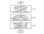
- FIG. 10 is a flowchart showing the calculation process of the electromagnetic noise frequency F n_r and the Doppler frequency F n_v in the electromagnetic noise detection unit 13.
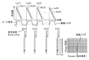
- FIG. 11 is an explanatory diagram showing a calculation process of the electromagnetic noise frequency F n_r and the Doppler frequency F n_v in the electromagnetic noise detection unit 13.
- Lo(1),..., Lo(K) are local oscillation signals output from the distribution unit 5 to the frequency mixing unit 9.
- Rx(1),..., Rx(K) are received signals output from the receiving antenna 7 to the frequency mixing unit 9.
- the signal acquisition timing (2) indicates the timing at which the spectrum calculation unit 41 acquires the digital data output from the ADC 11.
- the signal acquisition timing (2) is included in the period in which the radar signal is not output from the radar signal output unit 1, and the length of the signal acquisition timing (2) is approximately the same as one cycle of the local oscillation signal. Is. In the example of FIG. 11, the length of the signal acquisition timing (2) is approximately the same as one cycle of the local oscillation signal. However, this is merely an example, and the length of the signal acquisition timing (2) may be different from one cycle of the local oscillation signal. If the period during which the radar signal is not output from the radar signal output unit 1 is shorter than the period during which the radar signal is output from the radar signal output unit 1, the resolution of the detectable electromagnetic noise deteriorates. The presence or absence can be detected.
- the spectrum calculation unit 41 refers to the control signal output from the control unit 2 and identifies the period during which the radar signal is not output from the radar signal output unit 1.
- the spectrum calculation unit 41 acquires the digital data output from the ADC 11 at the signal acquisition timing (2) included in the specified period.
- the spectrum calculation unit 41 calculates the first frequency spectrum related to electromagnetic noise by Fourier transforming the digital data during the signal acquisition timing (2) in the distance direction (step ST21 in FIG. 10).
- FFT(1) indicates the Fourier transform in the distance direction.
- the beat signal is not generated by the frequency mixing unit 9. Therefore, even if the digital data is Fourier transformed in the distance direction by the spectrum calculation unit 41, the spectrum value of the received signal Rx(k) of the reflected wave is not integrated with the beat frequency F sb_r shown in the equation (1). ..
- the spectrum calculation unit 41 performs Fourier transform on the digital data in the distance direction, so that the spectrum value of the electromagnetic noise becomes the Doppler frequency F n_v corresponding to the relative speed between the radar device and the electromagnetic noise generation source shown in FIG. 1. Accumulated.
- the spectrum calculation unit 41 since the OFF period of the control signal output from the control unit 2 is K times, the spectrum calculation unit 41 performs Fourier transform in the distance direction on each of K different digital data, The K first frequency spectra are calculated. The spectrum calculation unit 41 outputs the calculated K first frequency spectra to the spectrum calculation unit 42.
- the spectrum calculation unit 42 acquires the K first frequency spectra output from the spectrum calculation unit 41.
- the spectrum calculation unit 42 calculates the second frequency spectrum related to the electromagnetic noise by Fourier-transforming the obtained K first frequency spectra in the relative velocity direction (step ST22 in FIG. 10).
- FFT(2) indicates the Fourier transform in the relative velocity direction.
- the spectrum calculation unit 42 performs the Fourier transform of the K first frequency spectra in the relative velocity direction, so that the spectrum value of the electromagnetic noise becomes the Doppler frequency F n_v corresponding to the relative velocity with the generation source of the electromagnetic noise. Accumulated.
- the spectrum value of the electromagnetic noise is integrated with the Doppler frequency F n — v corresponding to the relative velocity of 0.
- the spectrum value of the electromagnetic noise may be integrated with the Doppler frequency corresponding to the relative speed at which the relative speed to the electromagnetic noise generation source is other than zero.
- the spectrum value of the electromagnetic noise is integrated with the frequency F n_r of the electromagnetic noise. ..
- the frequency output section 43 Upon receiving the second frequency spectrum from the spectrum calculating section 42, the frequency output section 43 detects the peak value of the spectrum value in the second frequency spectrum. Since the process itself for detecting the peak value of the spectrum value is a known technique, its detailed description is omitted.
- the frequency output unit 43 outputs the beat frequency of the detected peak value to the distance/speed calculation unit 16 as the electromagnetic noise frequency Fn_r (step ST23 in FIG. 10).
- the frequency output unit 43 outputs the detected Doppler frequency of the peak value to the distance/velocity calculation unit 16 as the Doppler frequency F n_v corresponding to the relative speed with the electromagnetic noise generation source (step ST23 in FIG. 10).
- the distance/velocity calculation unit 16 acquires the set of the beat frequency F sb_r and the Doppler frequency F sb_v output from the frequency calculation unit 15. In the example of FIG. 9, since there are two peaks corresponding to one observation target and one electromagnetic noise, the distance/velocity calculation unit 16 causes the frequency calculation unit 15 to calculate the beat frequency F sb_r and the Doppler frequency F sb_v . Get 2 sets.
- the distance velocity calculation unit 16 acquires a set of the electromagnetic noise frequency F n_r and the Doppler frequency F n_v output from the electromagnetic noise detection unit 13. Since there is one peak corresponding to one electromagnetic noise in the example of FIG. 11, the distance/velocity calculation unit 16 outputs one set of the electromagnetic noise frequency F n_r and the Doppler frequency F n_v from the electromagnetic noise detection unit 13. get.
- the distance velocity calculation unit 16 includes two sets of the beat frequency F sb_r and the Doppler frequency F sb_v acquired from the frequency calculation unit 15, and the electromagnetic noise frequency F n_r and the Doppler frequency F n_v 1 acquired from the electromagnetic noise detection unit 13. Compare with two pairs. Of the two sets of the beat frequency F sb_r and the Doppler frequency F sb_v , one set matches the one set of the electromagnetic noise frequency F n_r and the Doppler frequency F n_v acquired from the electromagnetic noise detection unit 13. Specifically, of the two beat frequencies F sb_r , one beat frequency F sb_r matches the electromagnetic noise frequency F n_r .
- the Doppler frequency F sb_v corresponding to the beat frequency F sb_r that matches the electromagnetic noise frequency F n_r matches the Doppler frequency F n_v .
- Distance velocity calculation unit 16 as shown in FIG. 12, of the two sets in the beat frequency F Sb_r and Doppler frequency F Sb_v, discards a set that matches the set of frequencies F N_r and Doppler frequency F N_v electromagnetic noise .
- FIG. 12 is an explanatory diagram showing the beat frequency F sb_r corresponding to the distance to the observation target and the Doppler frequency F sb_v corresponding to the relative velocity with the observation target.
- the distance/velocity calculation unit 16 calculates the distance from the beat frequency F sb_r included in the group that remains without being discarded to the observation target (step ST3 in FIG. 4 ).
- the distance velocity calculation unit 16 calculates the relative velocity with respect to the observation target from the Doppler frequencies F sb_v included in the remaining sets that are not discarded (step ST3 in FIG. 4 ). Since the process itself for calculating the distance from the beat frequency F sb_r to the observation target is a known technique, detailed description thereof will be omitted. Further, since the process itself of calculating the relative velocity with respect to the observation target from the Doppler frequency F sb_v is a known technique, detailed description thereof will be omitted.
- the first embodiment described above uses the electromagnetic noise detection unit 13 that detects the electromagnetic noise input to the ADC 11 by using the digital data during the period in which the radar signal is not transmitted among the digital data output from the ADC 11. , Of the digital data output from the ADC 11, the digital data during the period during which the radar signal is being transmitted, and the electromagnetic noise detected by the electromagnetic noise detection unit 13 are used to detect an observation target.
- the radar device is configured so as to include Therefore, even if electromagnetic noise is input to the ADC 11, the radar device can suppress deterioration in detection accuracy of the observation target.
- the frequency output unit 53 of the frequency calculation unit 15 sets the beat frequency of the peak value of the spectrum value and the Doppler frequency of the peak value in the second frequency spectrum output from the spectrum calculation unit 52 to the distance. It is output to the speed calculator 16.
- the frequency output unit 53 may output the second frequency spectrum output from the spectrum calculation unit 52 to the distance/speed calculation unit 16.
- the frequency output unit 43 of the electromagnetic noise detection unit 13 causes the beat frequency of the peak value of the spectrum value and the Doppler of the peak value in the second frequency spectrum output from the spectrum calculation unit 42.
- the frequency is output to the distance/speed calculator 16.
- the frequency output unit 43 may output the second frequency spectrum output from the spectrum calculation unit 42 to the distance/speed calculation unit 16.
- Embodiment 2 In the radar device shown in FIG. 1, the radar signal output unit 1 intermittently repeatedly outputs a radar signal to the transmission/reception unit 4.
- a radar device including a switch 62 that repeatedly switches between connection and disconnection between the radar signal output unit 1 and the transmission/reception unit 4 will be described.
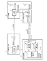
- FIG. 13 is a configuration diagram showing the radar device according to the second embodiment.
- the control unit 61 outputs a control signal (1) instructing the output of the radar signal to the signal source 3.
- the signal source 3 Upon receiving the control signal (1) from the control unit 2, the signal source 3 outputs the frequency-modulated signal of the continuous wave to the switch 62 as a radar signal.
- the control unit 61 also outputs a control signal (2) indicating the output timing of the radar signal to each of the switch 62 and the signal processing unit 12.
- the switch 62 has one end connected to the radar signal output side of the radar signal output unit 1 and the other end connected to the radar signal input side of the transceiver unit 4.
- the switch 62 connects and disconnects the radar signal output side of the radar signal output section 1 and the radar signal input side of the transmission/reception section 4 according to the output timing indicated by the control signal (2) output from the control section 2. Switch the connection repeatedly.
- the transmission/reception unit 4 targets the radar signal output from the radar signal output unit 1 as an observation target.
- the radar signal transmitted toward the observation target and reflected by the observation target is received as a reflected wave.
- FIG. 14 is an explanatory diagram showing an example of the measurement timing of the observation target in the radar device shown in FIG. 13
- the control unit 61 outputs a control signal (1) instructing the output of the radar signal to the signal source 3.
- the signal source 3 receives the control signal (1) from the control unit 2, as shown in FIG. 14, the signal source 3 outputs a frequency-modulated signal of a continuous wave to the switch 62 as a radar signal.
- the period in which the control signal (1) is ON is a period in which the radar signal is output, and the period in which the control signal (1) is OFF is a period in which the radar signal is not output.
- the control unit 61 outputs a control signal (2) indicating the output timing of the radar signal to each of the switch 62 and the signal processing unit 12.
- a period in which the control signal (2) is ON is a period in which the radar signal is output, and a period in which the control signal (2) is OFF is a period in which the radar signal is not output.
- the control signal (2) is ON for K times. Further, the period in which the control signal (2) is turned on and then turned off is K times.
- the control signal (2) is the same signal as the control signal shown in FIG. 7.
- the switch 62 connects and disconnects the radar signal output side of the radar signal output section 1 and the radar signal input side of the transmission/reception section 4 according to the output timing indicated by the control signal (2) output from the control section 2. Switch the connection repeatedly. As shown in FIG. 14, the switch 62 connects between the radar signal output side of the radar signal output section 1 and the radar signal input side of the transmission/reception section 4 while the control signal (2) is ON. .. As shown in FIG. 14, the switch 62 does not connect between the radar signal output side of the radar signal output unit 1 and the radar signal input side of the transmission/reception unit 4 while the control signal (2) is OFF.
- the transmitting/receiving unit 4 since the radar signal output from the radar signal output unit 1 is intermittently and repeatedly input to the transmitting/receiving unit 4, the transmitting/receiving unit 4 intermittently repeats the radar signal as in the first embodiment. Can radiate into space. Further, the transmitter/receiver 4 can intermittently and repeatedly output the local oscillation signal to the beat signal generator 8 as in the first embodiment.
- the operations of the beat signal generation unit 8, the ADC 11, and the signal processing unit 12 are similar to those of the radar device shown in FIG. 1, and thus detailed description thereof will be omitted.
- the radar device shown in FIG. 13 includes a switch 62 that repeatedly switches between connection and disconnection between the radar signal output side of the radar signal output unit 1 and the radar signal input side of the transmission/reception unit 4. Therefore, even when the radar device includes the signal source 3 that outputs the frequency-modulated signal of the continuous wave to the switch 62 as a radar signal, even if electromagnetic noise is input to the ADC 11 as in the radar device shown in FIG. It is possible to suppress deterioration of the detection accuracy of the target.
- FIG. 15 is a configuration diagram showing another radar device according to the second embodiment.
- the control unit 61 outputs the control signal (2) to each of the switch 63 and the signal processing unit 12. Since the frequency mixer 9 does not receive the local oscillation signal output from the distributor 5 while the switch 63 is OFF, it does not generate the beat signal and does not output the beat signal to the filter 10.
- the radar device shown in FIG. 15 can suppress deterioration of the detection accuracy of the observation target even when electromagnetic noise is input to the ADC 11, similarly to the radar devices shown in FIGS. 1 and 13.
- Embodiment 3 if the relative velocity with respect to the observation target is larger than the first threshold value, the calculation process of the frequency of electromagnetic noise and the calculation process of the Doppler frequency corresponding to the relative velocity with the source of the electromagnetic noise are performed.
- a radar device including the electromagnetic noise detector 71 that is not implemented will be described.
- FIG. 16 is a configuration diagram showing the radar device according to the third embodiment. 16, the same reference numerals as those in FIG. 1 indicate the same or corresponding portions, and thus the description thereof will be omitted.
- the frequency calculation unit 15 uses the digital data output from the ADC 11 during the specified period to determine the beat frequency F sb_r corresponding to the distance to the observation target and the observation target. The respective Doppler frequencies F sb_v corresponding to the relative speeds of and are calculated.
- the frequency calculation unit 15 outputs each of the calculated beat frequency F sb_r and the calculated Doppler frequency F sb_v to the distance/speed calculation unit 16.
- the frequency calculation unit 15 outputs the calculated Doppler frequency F sb_v to the electromagnetic noise detection unit 71.
- the electromagnetic noise detection unit 71 is realized by, for example, the electromagnetic noise detection circuit 21 shown in FIG. Similar to the electromagnetic noise detection unit 13 shown in FIG. 1, the electromagnetic noise detection unit 71 refers to the control signal output from the control unit 2 and determines that the radar signal is not being transmitted from the transmission/reception unit 4 during the radar period. The period during which the radar signal is not output from the signal output unit 1 is specified.
- the frequency calculation unit 15 calculates one or more Doppler frequencies F sb_v
- the electromagnetic noise detection unit 71 compares the relative speed indicated by each Doppler frequency F sb_v with the first threshold value.
- the frequency calculation unit 15 calculates two Doppler frequencies F sb_v, so the electromagnetic noise detection unit 71 determines that the two Doppler frequencies F sb_v are The relative speed shown is compared with a first threshold.
- Electromagnetic noise detection unit 71 the relative speed indicated by the respective Doppler frequency F Sb_v and based on a comparison result between the first threshold value, among the one or more Doppler frequency F Sb_v, showing one of the Doppler frequency F Sb_v It is determined whether the relative speed is less than or equal to the first threshold. If the electromagnetic noise detection unit 71 determines that the relative speed indicated by any one of the Doppler frequencies F sb_v is less than or equal to the first threshold value, the electromagnetic noise input to the ADC 11 is detected using the digital data during the specified period. Each of the frequency F n_r and the Doppler frequency F n_v corresponding to the relative speed with respect to the electromagnetic noise generation source is calculated.
- the electromagnetic noise detection unit 71 determines that all of the relative speeds indicated by the one or more Doppler frequencies F sb_v are larger than the first threshold value, the calculation process of the electromagnetic noise frequency F n_r and the calculation of the Doppler frequency F n_v are performed. Do not perform each of the treatments.
- the first threshold value may be stored in the internal memory of the spectrum calculation unit 44 (see FIG. 17) in the electromagnetic noise detection unit 71, or may be given from the outside.
- the first threshold value is 0 or a value close to 0. As a value close to 0, a value of 1 [km/hour] can be considered, for example. Further, the first threshold may be a value obtained from a result of conducting an electromagnetic noise test in advance.
- the electromagnetic noise detection unit 71 outputs each of the calculated electromagnetic noise frequency F n_r and the calculated Doppler frequency F n_v to the distance velocity calculation unit 16.
- FIG. 17 is a configuration diagram showing the electromagnetic noise detection unit 71 of the signal processing unit 12.
- the spectrum calculation unit 44 refers to the control signal output from the control unit 2 and specifies the period during which the radar signal is not output from the radar signal output unit 1.
- the spectrum calculation unit 44 compares the relative speed indicated by each Doppler frequency F sb_v with the first threshold value.
- Spectrum calculation unit 44 based on a result of comparison between the respective Doppler frequency F Sb_v relative velocity and the first threshold indicating, among the one or more Doppler frequency F Sb_v, relative showing one of the Doppler frequency F Sb_v It is determined whether the speed is less than or equal to the first threshold. If the spectrum calculation unit 44 determines that the relative speed indicated by one of the Doppler frequencies F sb_v is less than or equal to the first threshold value, then the digital data output from the ADC 11 within the specified period is set to the distance direction. The first frequency spectrum related to the electromagnetic noise is calculated by performing the Fourier transform on the.
- the spectrum calculation unit 44 Since the ADC 11 repeatedly outputs the digital data in the specified period from the ADC 11, the spectrum calculation unit 44 Fourier-transforms each of the repeatedly output digital data in the distance direction to thereby obtain a plurality of electromagnetic noise-related first signals.
- the frequency spectrum of 1 is calculated.
- the spectrum calculation unit 44 outputs the plurality of first frequency spectra related to the calculated electromagnetic noise to the spectrum calculation unit 42.
- the spectrum calculation unit 44 determines that all of the relative velocities indicated by the one or more Doppler frequencies F sb_v are larger than the first threshold value, by performing Fourier transform in the distance direction on the digital data during the specified period, The process of calculating the first frequency spectrum related to electromagnetic noise is not performed.
- the frequency calculation unit 15 calculates each of the beat frequency F sb_r corresponding to the distance to the observation target and the Doppler frequency F sb_v corresponding to the relative speed with the observation target, as in the first embodiment.
- the frequency calculation unit 15 outputs each of the calculated beat frequency F sb_r and the calculated Doppler frequency F sb_v to the distance velocity calculation unit 16, as in the first embodiment.
- the frequency calculation unit 15 outputs the calculated Doppler frequency F sb_v to the electromagnetic noise detection unit 71.
- the spectrum calculation unit 44 of the electromagnetic noise detection unit 71 refers to the control signal output from the control unit 2 and outputs the radar signal from the radar signal output unit 1 similarly to the spectrum calculation unit 41 shown in FIG. Identify the periods that are not.
- the spectrum calculation unit 44 compares the relative speed indicated by each Doppler frequency F sb_v with the first threshold value. For example, if there is one observation target and one electromagnetic noise, the frequency calculation unit 15 calculates two Doppler frequencies F sb_v .
- the spectrum calculation unit 44 compares the relative speed indicated by the two Doppler frequencies F sb_v with the first threshold value. If the relative velocity is almost 0, electromagnetic noise is likely to be input to the ADC 11 and superimposed on the beat signal. When the relative speed is almost 0, the electromagnetic noise input to the ADC 11 is assumed to be the electromagnetic noise generated from any component mounted on the radar device shown in FIG. On the other hand, if the relative speed is high, electromagnetic noise is less likely to be input to the ADC 11 and superimposed on the beat signal.
- Spectrum calculation unit 44 based on a result of comparison between the respective Doppler frequency F Sb_v relative velocity and the first threshold indicating, among the one or more Doppler frequency F Sb_v, relative showing one of the Doppler frequency F Sb_v It is determined whether the speed is less than or equal to the first threshold. If the spectrum calculation unit 44 determines that the relative speed indicated by any of the Doppler frequencies F sb_v is less than or equal to the first threshold, the digital calculation unit 44 acquires the digital data output from the ADC 11 during the specified period. .. Similar to the spectrum calculating unit 41 shown in FIG. 5, the spectrum calculating unit 44 calculates the first frequency spectrum related to electromagnetic noise by performing Fourier transform on the acquired digital data in the distance direction.
- the spectrum calculation unit 44 determines that all of the relative velocities indicated by the one or more Doppler frequencies F sb_v are larger than the first threshold value, by performing Fourier transform in the distance direction on the digital data during the specified period, The process of calculating the first frequency spectrum related to electromagnetic noise is not performed. Similar to the spectrum calculating unit 41 shown in FIG. 5, when the spectrum calculating unit 44 calculates the K first frequency spectra related to electromagnetic noise, the spectrum calculates the K first frequency spectra related to the calculated electromagnetic noise. It is output to the calculation unit 42.
- the spectrum calculating unit 42 When the spectrum calculating unit 41 outputs the K first frequency spectra, the spectrum calculating unit 42 acquires the K first frequency spectra.
- the spectrum calculation unit 42 calculates the second frequency spectrum related to the electromagnetic noise by Fourier-transforming the acquired K first frequency spectra in the relative velocity direction, as in the first embodiment.
- the frequency output section 43 Upon receiving the second frequency spectrum from the spectrum calculating section 42, the frequency output section 43 detects the peak value of the spectrum value in the second frequency spectrum. The frequency output unit 43 outputs the detected beat frequency of the peak value to the distance velocity calculation unit 16 as the electromagnetic noise frequency Fn_r . The frequency output unit 43 outputs the Doppler frequency of the detected peak value to the distance/velocity calculation unit 16 as the Doppler frequency F n_v corresponding to the relative velocity with the electromagnetic noise source.
- the electromagnetic noise detection unit 71 determines whether any one of the one or more Doppler frequencies F sb_v. If the relative speed indicated by F sb_v is less than or equal to the first threshold value, the calculation process of the frequency F n_r of the electromagnetic noise input to the ADC 11 and the calculation process of the Doppler frequency F n_v corresponding to the relative speed of the electromagnetic noise source. Perform each of the above.
- the electromagnetic noise detection unit 71 calculates the frequency F n_r of the electromagnetic noise input to the ADC 11 and generates the electromagnetic noise.
- the radar device is configured so that each of the calculation processes of the Doppler frequency F n — v corresponding to the relative velocity with the source is not performed. Therefore, the radar device can suppress the deterioration of the detection accuracy of the observation target even when the electromagnetic noise is input to the ADC 11, and the calculation of the electromagnetic noise detecting unit 71 is more difficult than the electromagnetic noise detecting unit 13 shown in FIG. The processing load can be reduced.
- the electromagnetic noise detection section 71 causes the electromagnetic noise frequency F n — r calculation process and the Doppler frequency. Each of the calculation processes of the frequency F n_v is not performed. If all the relative velocities indicated by the one or more Doppler frequencies F n — v are larger than the first threshold value, the control unit 2 controls the radar signal output unit 1 to shorten the period in which no radar signal is output. May be.
- control unit 2 Since the control unit 2 shortens the period in which the radar signal is not output from the radar signal output unit 1, each calculation cycle of the distance to the observation target and the relative velocity with the observation target is shortened, and the distance and the relative velocity are calculated. The calculation frequency of each becomes high.
- the electromagnetic noise detection unit 71 compares the relative speed indicated by each Doppler frequency F sb_v calculated by the frequency calculation unit 15 with the first threshold value.
- the electromagnetic noise detection unit 71 causes the relative speed indicated by each Doppler frequency F sb_v calculated by the frequency calculation unit 15 and the movement of the radar device shown in FIG. 16 which is its own radar device. You may make it compare the difference with speed and a 2nd threshold value. If the radar device shown in FIG. 16 is mounted on a vehicle such as an automobile, the electromagnetic noise detecting section 71 can acquire the moving speed of the radar device shown in FIG. 16 from the vehicle.
- the second threshold value may be stored in the internal memory of the spectrum calculation unit 44 (see FIG.
- the second threshold value is 0 or a value close to 0. As a value close to 0, a value of 1 [km/hour] can be considered, for example. Further, the second threshold may be a value obtained from a result of conducting an electromagnetic noise test in advance.
- electromagnetic noise may be input to the ADC 11 and superimposed on the beat signal. high.
- the electromagnetic noise input to the ADC 11 is, for example, the electromagnetic noise generated from the wireless power feeding device existing near the radar device shown in FIG.
- the wireless power supply device is installed in a gas station, a convenience store, or the like, and wirelessly charges a battery of an electric vehicle.
- the electromagnetic noise detection unit 71 is based on the comparison result between the relative speed indicated by each Doppler frequency F sb_v calculated by the frequency calculation unit 15 and the moving speed of the radar device shown in FIG. 16, and the second threshold value. Then, it is determined whether or not any one of the differences is equal to or less than the second threshold value. If the electromagnetic noise detection unit 71 determines that any difference is less than or equal to the second threshold value, the electromagnetic noise frequency F n_r and the electromagnetic noise of the electromagnetic noise input to the ADC 11 are calculated using the digital data during the specified period. Each of the Doppler frequencies Fn_v corresponding to the relative velocity with the generation source is calculated.
- the electromagnetic noise detection unit 71 outputs each of the calculated electromagnetic noise frequency F n_r and the calculated Doppler frequency F n_v to the distance velocity calculation unit 16. If it is determined that all the differences are larger than the second threshold, the electromagnetic noise detection unit 71 does not perform the calculation process of the electromagnetic noise frequency Fn_r and the calculation process of the Doppler frequency Fn_v .
- FIG. 18 is a configuration diagram showing the radar device according to the fourth embodiment. 18, the same reference numerals as those in FIG. 1 indicate the same or corresponding portions, and therefore their explanations are omitted.
- the radar signal output unit 80 includes a control unit 81 and a signal source 3. Similar to the radar signal output unit 1 shown in FIG. 1, the radar signal output unit 80 intermittently repeatedly outputs to the transceiver unit 4 a frequency modulation signal whose frequency changes with the passage of time as a radar signal. The radar signal output unit 80 changes the frequency bandwidth BW of the radar signal or the sweep time T of the radar signal when a predetermined condition is satisfied.
- the control unit 81 Similar to the control unit 2 shown in FIG. 1, the control unit 81 outputs a control signal indicating the output timing of the radar signal to each of the signal source 3 and the signal processing unit 12.
- the control unit 81 acquires the beat frequency F sb_r corresponding to the distance to the observation target calculated by the distance/speed calculation unit 16.
- the control unit 81 acquires the Doppler frequency F sb_v corresponding to the relative speed with the observation target calculated by the distance speed calculation unit 16 among the Doppler frequencies F sb_v calculated by the frequency calculation unit 15.
- the control unit 81 acquires each of the electromagnetic noise frequency Fn_r calculated by the electromagnetic noise detection unit 13 and the Doppler frequency Fn_v corresponding to the relative speed to the electromagnetic noise generation source.
- the control unit 81 compares the difference between the acquired beat frequency F sb_r corresponding to the distance to the observation target and the acquired frequency F n_r of electromagnetic noise with the third threshold value.
- Control unit 81 a Doppler frequency F Sb_v corresponding to the relative speed between the obtained observation target, the difference between the Doppler frequency F N_v corresponding to the relative velocity of a source of electromagnetic noise acquired, and the fourth threshold value To compare.
- the control unit 81 determines that the difference between the beat frequency F sb_r and the electromagnetic noise frequency F n_r is equal to or less than a third threshold, and the difference between the Doppler frequency F sb_v and the Doppler frequency F n_v is equal to or less than a fourth threshold.
- the signal source 3 is controlled so as to change the frequency bandwidth BW of the radar signal or the sweep time T of the radar signal.
- Each of the third threshold value and the fourth threshold value may be stored in the internal memory of the control unit 81 or may be given from the outside.
- Each of the third threshold value and the fourth threshold value is 0 or a value close to 0. As a value close to 0, a value of 1 or 2 etc. [Hz] can be considered. Further, each of the third threshold value and the fourth threshold value may be a value obtained from a result of performing an electromagnetic noise test in advance.
- the distance velocity calculation unit 16 calculates the distance to the observation target and the relative velocity with respect to the observation target, as in the first embodiment.
- the distance speed calculation unit 16 outputs the beat frequency F sb_r corresponding to the calculated distance to the observation target to the control unit 81, and outputs the Doppler frequency F sb_v corresponding to the calculated relative speed to the observation target to the control unit 81. To do.
- the distance velocity calculation unit 16 outputs only one set of the beat frequency F sb_r and the Doppler frequency F sb_v .
- the electromagnetic noise detection unit 13 controls the calculated electromagnetic noise frequency F n_r and the Doppler frequency F n_v , respectively. Output to 81.
- the number of electromagnetic noise is one and only one set of the electromagnetic noise frequency F n_r and the Doppler frequency F n_v is output.
- the control unit 81 acquires each of the beat frequency F sb_r and the Doppler frequency F sb_v output from the distance/velocity calculation unit 16, and calculates the electromagnetic noise frequency F n_r and the Doppler frequency F n_v output from the electromagnetic noise detection unit 13. Get each.
- the control unit 81 compares the difference between the acquired beat frequency F sb_r and the acquired frequency F n_r of electromagnetic noise with the third threshold value.
- the control unit 81 compares the difference between the acquired Doppler frequency F sb_v and the acquired Doppler frequency F n_v with the fourth threshold value.
- the control unit 81 determines that the difference between the beat frequency F sb_r and the electromagnetic noise frequency F n_r is equal to or less than a third threshold, and the difference between the Doppler frequency F sb_v and the Doppler frequency F n_v is equal to or less than a fourth threshold.
- the signal source 3 is controlled so as to change the frequency bandwidth BW of the radar signal or the sweep time T of the radar signal.
- the control unit 81 changes the frequency bandwidth BW of the radar signal or the sweep time T of the radar signal, so that the spectrum value of the observation target and the spectrum value of the electromagnetic noise are different beat frequencies from each other, or are mutually different. It becomes integrated into different Doppler frequencies. Therefore, the distance/velocity calculation unit 16 can calculate the distance to the observation target and the relative velocity with respect to the observation target without being affected by the electromagnetic noise superimposed on the beat signal.
- the radar signal output unit 80 calculates the beat frequency corresponding to the distance to the observation target calculated by the distance/speed calculation unit 16 among the beat frequencies calculated by the frequency calculation unit 15, and the electromagnetic wave.
- the difference with the frequency of the electromagnetic noise calculated by the noise detection unit 13 is equal to or less than the third threshold value, and among the Doppler frequencies calculated by the frequency calculation unit 15, the observation target calculated by the distance velocity calculation unit 16 If the difference between the Doppler frequency corresponding to the relative velocity with the Doppler frequency and the Doppler frequency calculated by the electromagnetic noise detection unit 13 is less than or equal to the fourth threshold, the frequency bandwidth BW of the radar signal or the sweep time of the radar signal.
- the radar device was configured to change T.
- the radar device uses the ADC 11. It is possible to suppress deterioration of the detection accuracy of the observation target due to the input of electromagnetic noise.
- FIG. 19 is a configuration diagram showing an in-vehicle device according to the fifth embodiment.
- a radar device 90 is the radar device according to any one of the first to fourth embodiments.
- the radar device 90 outputs the distance to the observation target and the relative speed to the observation target calculated by the distance/speed calculation unit 16 of the observation target detection unit 14 to the control unit 91 of the vehicle.
- the radar device 90 outputs the frequency F n_r of electromagnetic noise calculated by the electromagnetic noise detector 13 and the Doppler frequency F n_v corresponding to the relative speed to the source of the electromagnetic noise to the control unit 91 of the vehicle. ..
- the control unit 91 is a device that controls the engine, steering, brakes, or the like of the automobile.
- the radar device 90 When the distance/velocity calculation unit 16 calculates the distance to the observation target and the relative speed to the observation target, the radar device 90 outputs the distance to the observation target and the relative speed to the observation target to the control unit 91. To do.
- the control unit 91 acquires the distance from the radar device 90 to the observation target and the relative speed to the observation target, based on the acquired distance and the acquired relative speed, for example, a vehicle including the in-vehicle device shown in FIG. And the risk of collision with the observation target is determined. Any determination method may be used as long as it can determine the risk of collision, and the control unit 91 uses a known determination method.
- the control unit 91 determines that there is a risk of collision, for example, the brake of the automobile is automatically activated.
- the control unit 91 determines that there is a risk of collision, the control unit 91 controls the steering so that the traveling direction of the automobile is switched, for example.
- control unit 91 implements, for example, automatic driving of an automobile based on a combination of sensor information detected by a sensor (not shown), the acquired distance to the observation target, and the relative speed of the acquired observation target. To do.
- the control unit 91 for example, based on each of the frequency F n_r and the Doppler frequency F n_v of the electromagnetic noise output from the radar device 90, for example, the distance to the acquired observation target and the relative speed with the acquired observation target.
- Determine reliability Any determination method may be used as long as it can determine the reliability, and the control unit 91 uses a known determination method.
- control unit 91 uses, for example, each of the acquired distance to the observation target and the acquired relative speed with the observation target to perform automatic driving of the automobile, for example.
- control unit 91 does not use the acquired distance to the observation target and the acquired relative speed with the observation target, for example, when performing automatic driving of the automobile.
- the observation target detection unit 14 outputs the distance to the observation target calculated by the distance/speed calculation unit 16 and the relative speed with respect to the observation target to the control unit 91 of the vehicle, and electromagnetic noise is generated.
- the radar device is configured to output the beat frequency and the Doppler frequency calculated by the detection unit 13 to the control unit 91. Therefore, the control unit 91 uses the distance to the observation target and the relative speed with respect to the observation target, for example, when controlling the automobile, for example, the reliability of the distance to the observation target and the relative speed with respect to the observation target. Can be determined.
- the invention of the present application is capable of freely combining the respective embodiments, modifying any constituent element of each embodiment, or omitting any constituent element in each embodiment. ..
- This invention is suitable for a radar device that detects an observation target, an observation target detection method, and an in-vehicle device.
Landscapes
- Engineering & Computer Science (AREA)
- Radar, Positioning & Navigation (AREA)
- Remote Sensing (AREA)
- Physics & Mathematics (AREA)
- Computer Networks & Wireless Communication (AREA)
- General Physics & Mathematics (AREA)
- Electromagnetism (AREA)
- Radar Systems Or Details Thereof (AREA)
Abstract
La présente invention concerne un dispositif radar qui est configuré de façon à comprendre : une unité de détection de bruit électromagnétique (13) qui utilise des données numériques pendant une période durant laquelle un signal radar n'est pas émis, parmi les données numériques délivrées en sortie par un CAN (11), pour détecter une entrée de bruit électromagnétique vers le CAN (11) ; et une unité de détection d'objet à observer (14) qui utilise des données numériques pendant une période durant laquelle un signal radar est transmis, parmi les données numériques délivrées en sortie par le CAN (11), et le bruit électromagnétique détecté par l'unité de détection de bruit électromagnétique (13) pour détecter un objet à observer.
Priority Applications (6)
| Application Number | Priority Date | Filing Date | Title |
|---|---|---|---|
| PCT/JP2019/004877 WO2020165952A1 (fr) | 2019-02-12 | 2019-02-12 | Dispositif radar, procédé de détection d'objet à observer, et dispositif embarqué |
| JP2020570209A JP6880344B2 (ja) | 2019-02-12 | 2020-02-05 | レーダ装置、観測対象検出方法及び車載装置 |
| DE112020000412.0T DE112020000412B4 (de) | 2019-02-12 | 2020-02-05 | Radarvorrichtung, verfahren zur ermittlung von beobachtungszielen und vorrichtung im fahrzeug |
| PCT/JP2020/004310 WO2020166442A1 (fr) | 2019-02-12 | 2020-02-05 | Dispositif radar, procédé de détection d'objet à observer, et dispositif embarqué |
| CN202080012474.1A CN113383245B (zh) | 2019-02-12 | 2020-02-05 | 雷达装置、观测对象检测方法及车载装置 |
| US17/365,417 US11921196B2 (en) | 2019-02-12 | 2021-07-01 | Radar device, observation target detecting method, and in-vehicle device |
Applications Claiming Priority (1)
| Application Number | Priority Date | Filing Date | Title |
|---|---|---|---|
| PCT/JP2019/004877 WO2020165952A1 (fr) | 2019-02-12 | 2019-02-12 | Dispositif radar, procédé de détection d'objet à observer, et dispositif embarqué |
Publications (1)
| Publication Number | Publication Date |
|---|---|
| WO2020165952A1 true WO2020165952A1 (fr) | 2020-08-20 |
Family
ID=72043798
Family Applications (2)
| Application Number | Title | Priority Date | Filing Date |
|---|---|---|---|
| PCT/JP2019/004877 WO2020165952A1 (fr) | 2019-02-12 | 2019-02-12 | Dispositif radar, procédé de détection d'objet à observer, et dispositif embarqué |
| PCT/JP2020/004310 WO2020166442A1 (fr) | 2019-02-12 | 2020-02-05 | Dispositif radar, procédé de détection d'objet à observer, et dispositif embarqué |
Family Applications After (1)
| Application Number | Title | Priority Date | Filing Date |
|---|---|---|---|
| PCT/JP2020/004310 WO2020166442A1 (fr) | 2019-02-12 | 2020-02-05 | Dispositif radar, procédé de détection d'objet à observer, et dispositif embarqué |
Country Status (5)
| Country | Link |
|---|---|
| US (1) | US11921196B2 (fr) |
| JP (1) | JP6880344B2 (fr) |
| CN (1) | CN113383245B (fr) |
| DE (1) | DE112020000412B4 (fr) |
| WO (2) | WO2020165952A1 (fr) |
Cited By (3)
| Publication number | Priority date | Publication date | Assignee | Title |
|---|---|---|---|---|
| JPWO2022203006A1 (fr) * | 2021-03-25 | 2022-09-29 | ||
| TWI789912B (zh) * | 2021-09-16 | 2023-01-11 | 立積電子股份有限公司 | 調頻連續波雷達裝置及其訊號處理方法 |
| DE112021006774T5 (de) | 2021-03-11 | 2023-11-02 | Mitsubishi Electric Corporation | Radarvorrichtung und fahrzeuginterne vorrichtung mit radarvorrichtung |
Citations (5)
| Publication number | Priority date | Publication date | Assignee | Title |
|---|---|---|---|---|
| JPH10253750A (ja) * | 1997-03-13 | 1998-09-25 | Mitsubishi Electric Corp | Fm−cwレーダ装置 |
| JPH1164502A (ja) * | 1997-08-22 | 1999-03-05 | Mitsubishi Electric Corp | 障害物検出レーダ装置 |
| JP2011237268A (ja) * | 2010-05-10 | 2011-11-24 | Mitsubishi Electric Corp | Fm−cwレーダ装置 |
| US20120146845A1 (en) * | 2010-12-08 | 2012-06-14 | International Business Machines Corporation | Narrow-Band Wide-Range Frequency Modulation Continuous Wave (FMCW) Radar System |
| JP2013096903A (ja) * | 2011-11-02 | 2013-05-20 | Denso Corp | レーダ装置 |
Family Cites Families (37)
| Publication number | Priority date | Publication date | Assignee | Title |
|---|---|---|---|---|
| JP2759576B2 (ja) * | 1992-02-27 | 1998-05-28 | 本田技研工業株式会社 | Fmレーダ装置 |
| JP2793487B2 (ja) * | 1993-12-01 | 1998-09-03 | 本田技研工業株式会社 | Fm−cwレーダ装置 |
| JP3251154B2 (ja) * | 1995-09-13 | 2002-01-28 | 富士通株式会社 | 距離・速度検出用レーダ装置 |
| JPH09133765A (ja) * | 1995-11-10 | 1997-05-20 | Hitachi Ltd | Fm−cwレーダ装置 |
| JP3534164B2 (ja) * | 1998-04-28 | 2004-06-07 | トヨタ自動車株式会社 | Fm−cwレーダ装置 |
| JP2003139847A (ja) * | 2001-10-31 | 2003-05-14 | Fujitsu Ltd | 通信処理装置 |
| FI110966B (fi) * | 2001-11-21 | 2003-04-30 | Vaisala Oyj | Menetelmä taajuusmoduloidun, katkotun jatkuva-aaltotutkasignaalin (FMICW) käsittelemiseksi |
| JP4032881B2 (ja) * | 2002-08-28 | 2008-01-16 | 株式会社豊田中央研究所 | Fm−cwレーダ装置 |
| FR2846751B1 (fr) * | 2002-10-31 | 2005-01-14 | Cynove | Procedes et dispositifs de mesure de la vitesse de vehicules en mouvement |
| JP2004271262A (ja) * | 2003-03-06 | 2004-09-30 | Mitsubishi Electric Corp | Fm−cwレーダ装置 |
| JP2005009950A (ja) * | 2003-06-18 | 2005-01-13 | Matsushita Electric Works Ltd | レーダ装置 |
| US7683827B2 (en) * | 2004-12-15 | 2010-03-23 | Valeo Radar Systems, Inc. | System and method for reducing the effect of a radar interference signal |
| EP1881344A4 (fr) * | 2005-05-13 | 2011-03-09 | Murata Manufacturing Co | Radar |
| JP5226185B2 (ja) * | 2006-02-15 | 2013-07-03 | 富士通株式会社 | 探知測距装置 |
| JP2008209225A (ja) * | 2007-02-26 | 2008-09-11 | Fujitsu Ten Ltd | レーダ装置 |
| DE102008038365A1 (de) | 2008-07-02 | 2010-01-07 | Adc Automotive Distance Control Systems Gmbh | Fahrzeug-Radarsystem und Verfahren zur Bestimmung einer Position zumindest eines Objekts relativ zu einem Fahrzeug |
| JP2010112937A (ja) * | 2008-11-10 | 2010-05-20 | Fujitsu Ten Ltd | 信号処理装置、及びレーダ装置 |
| KR101040257B1 (ko) * | 2008-11-14 | 2011-06-09 | 엘아이지넥스원 주식회사 | 레이더 시스템 및 이를 이용한 신호 처리 방법 |
| US8638254B2 (en) * | 2009-08-27 | 2014-01-28 | Fujitsu Ten Limited | Signal processing device, radar device, vehicle control system, signal processing method, and computer-readable medium |
| JP5307068B2 (ja) * | 2010-03-31 | 2013-10-02 | 古河電気工業株式会社 | レーダ装置 |
| EP2390679B1 (fr) * | 2010-05-27 | 2012-10-03 | Mitsubishi Electric R&D Centre Europe B.V. | Radar d'automobile doté d'évitement d'interférence de fréquence radio |
| JP5267538B2 (ja) | 2010-11-05 | 2013-08-21 | 株式会社デンソー | ピーク検出閾値の設定方法、物標情報生成装置、プログラム |
| JP5871559B2 (ja) * | 2011-10-20 | 2016-03-01 | 三菱電機株式会社 | レーダ装置 |
| JP5812339B2 (ja) * | 2011-10-28 | 2015-11-11 | 株式会社ノーリツ | 燃焼装置 |
| JP5978962B2 (ja) * | 2012-11-30 | 2016-08-24 | 株式会社デンソー | Fmcwレーダ装置 |
| JP6131752B2 (ja) * | 2013-07-23 | 2017-05-24 | 株式会社豊田中央研究所 | 車両周囲環境報知システム |
| US9448300B2 (en) * | 2014-05-28 | 2016-09-20 | Nxp B.V. | Signal-based data compression |
| US9784828B2 (en) * | 2014-08-27 | 2017-10-10 | Texas Insturments Incorporated | FMCW doppler processing algorithm for achieving CW performance |
| JP6226084B2 (ja) * | 2014-11-19 | 2017-11-08 | 三菱電機株式会社 | レーダ装置 |
| US10067221B2 (en) * | 2015-04-06 | 2018-09-04 | Texas Instruments Incorporated | Interference detection in a frequency modulated continuous wave (FMCW) radar system |
| JP6696678B2 (ja) * | 2015-09-17 | 2020-05-20 | 株式会社デンソーテン | レーダ装置、レーダ装置用の信号処理装置及び測速方法 |
| DE102015120733B4 (de) * | 2015-11-30 | 2017-11-02 | Infineon Technologies Ag | Radarvorrichtung mit Schätzung des Phasenrauschens |
| US11002829B2 (en) * | 2016-04-15 | 2021-05-11 | Mediatek Inc. | Radar interference mitigation method and apparatus |
| JP2018080938A (ja) * | 2016-11-14 | 2018-05-24 | 株式会社デンソーテン | レーダ装置および物標検知方法 |
| JP2019015797A (ja) | 2017-07-04 | 2019-01-31 | 住友電気工業株式会社 | 光結合部材及び光通信モジュール |
| EP3444628A1 (fr) * | 2017-08-18 | 2019-02-20 | Nxp B.V. | Unité radar, circuit intégré et procédés de détection et d'atténuation des interférences mutuelles |
| US11175376B2 (en) * | 2018-09-18 | 2021-11-16 | Infineon Technologies Ag | System and method for determining interference in a radar system |
-
2019
- 2019-02-12 WO PCT/JP2019/004877 patent/WO2020165952A1/fr active Application Filing
-
2020
- 2020-02-05 JP JP2020570209A patent/JP6880344B2/ja active Active
- 2020-02-05 CN CN202080012474.1A patent/CN113383245B/zh active Active
- 2020-02-05 WO PCT/JP2020/004310 patent/WO2020166442A1/fr active Application Filing
- 2020-02-05 DE DE112020000412.0T patent/DE112020000412B4/de active Active
-
2021
- 2021-07-01 US US17/365,417 patent/US11921196B2/en active Active
Patent Citations (5)
| Publication number | Priority date | Publication date | Assignee | Title |
|---|---|---|---|---|
| JPH10253750A (ja) * | 1997-03-13 | 1998-09-25 | Mitsubishi Electric Corp | Fm−cwレーダ装置 |
| JPH1164502A (ja) * | 1997-08-22 | 1999-03-05 | Mitsubishi Electric Corp | 障害物検出レーダ装置 |
| JP2011237268A (ja) * | 2010-05-10 | 2011-11-24 | Mitsubishi Electric Corp | Fm−cwレーダ装置 |
| US20120146845A1 (en) * | 2010-12-08 | 2012-06-14 | International Business Machines Corporation | Narrow-Band Wide-Range Frequency Modulation Continuous Wave (FMCW) Radar System |
| JP2013096903A (ja) * | 2011-11-02 | 2013-05-20 | Denso Corp | レーダ装置 |
Cited By (5)
| Publication number | Priority date | Publication date | Assignee | Title |
|---|---|---|---|---|
| DE112021006774T5 (de) | 2021-03-11 | 2023-11-02 | Mitsubishi Electric Corporation | Radarvorrichtung und fahrzeuginterne vorrichtung mit radarvorrichtung |
| JPWO2022203006A1 (fr) * | 2021-03-25 | 2022-09-29 | ||
| WO2022203006A1 (fr) * | 2021-03-25 | 2022-09-29 | 三菱電機株式会社 | Dispositif radar |
| JP7345703B2 (ja) | 2021-03-25 | 2023-09-15 | 三菱電機株式会社 | レーダ装置 |
| TWI789912B (zh) * | 2021-09-16 | 2023-01-11 | 立積電子股份有限公司 | 調頻連續波雷達裝置及其訊號處理方法 |
Also Published As
| Publication number | Publication date |
|---|---|
| CN113383245A (zh) | 2021-09-10 |
| DE112020000412B4 (de) | 2023-03-02 |
| CN113383245B (zh) | 2024-04-02 |
| WO2020166442A1 (fr) | 2020-08-20 |
| US11921196B2 (en) | 2024-03-05 |
| JP6880344B2 (ja) | 2021-06-02 |
| US20210325531A1 (en) | 2021-10-21 |
| JPWO2020166442A1 (ja) | 2021-03-25 |
| DE112020000412T5 (de) | 2021-09-30 |
Similar Documents
| Publication | Publication Date | Title |
|---|---|---|
| WO2020166442A1 (fr) | Dispositif radar, procédé de détection d'objet à observer, et dispositif embarqué | |
| JP6560165B2 (ja) | レーダ装置 | |
| JP3491418B2 (ja) | Fmcwレーダ装置 | |
| JP4769684B2 (ja) | 電子走査式レーダ装置 | |
| US7460058B2 (en) | Radar | |
| US9331797B2 (en) | RF receiver with testing capability | |
| US10746853B2 (en) | On-board radar apparatus and notification system | |
| JP4188361B2 (ja) | 車載用パルスレーダ装置 | |
| JP2004004120A (ja) | Fmcwレーダ装置 | |
| JP6771699B2 (ja) | レーダ装置 | |
| JP2000081480A (ja) | Fmcwレーダ装置及び記録媒体並びに車両制御装置 | |
| US8188909B2 (en) | Observation signal processing apparatus | |
| JP2002062352A (ja) | 車載用レーダ装置 | |
| WO2022269907A1 (fr) | Appareil radar et dispositif d'évitement d'onde d'interférence | |
| JP6821106B1 (ja) | レーダ信号処理装置、レーダ信号処理方法、レーダ装置及び車載装置 | |
| JP7282286B2 (ja) | レーダ装置、及びレーダ装置を備えた車載装置 | |
| JP2019194627A (ja) | レーダ信号処理装置およびレーダ装置 | |
| WO2014104299A1 (fr) | Dispositif radar à bord d'un véhicule | |
| JP6987300B2 (ja) | レーダ装置、信号処理方法及び車載装置 | |
| WO2011136281A1 (fr) | Dispositif de radar embarqué et système de radar embarqué | |
| WO2023062803A1 (fr) | Dispositif radar et procédé de détection de contremesure d'interférence pour dispositif radar | |
| JP4225804B2 (ja) | レーダ装置 | |
| JP3463747B2 (ja) | Fm−cwレーダ装置 | |
| JP2002323557A (ja) | Fm−cwレーダ装置 | |
| JP2014215244A (ja) | レーダ受信装置 |
Legal Events
| Date | Code | Title | Description |
|---|---|---|---|
| 121 | Ep: the epo has been informed by wipo that ep was designated in this application |
Ref document number: 19915488 Country of ref document: EP Kind code of ref document: A1 |
|
| NENP | Non-entry into the national phase |
Ref country code: DE |
|
| 122 | Ep: pct application non-entry in european phase |
Ref document number: 19915488 Country of ref document: EP Kind code of ref document: A1 |
|
| NENP | Non-entry into the national phase |
Ref country code: JP |