WO2020162147A1 - ドア用配線モジュール及びドア用配線モジュールの製造方法 - Google Patents
ドア用配線モジュール及びドア用配線モジュールの製造方法 Download PDFInfo
- Publication number
- WO2020162147A1 WO2020162147A1 PCT/JP2020/001673 JP2020001673W WO2020162147A1 WO 2020162147 A1 WO2020162147 A1 WO 2020162147A1 JP 2020001673 W JP2020001673 W JP 2020001673W WO 2020162147 A1 WO2020162147 A1 WO 2020162147A1
- Authority
- WO
- WIPO (PCT)
- Prior art keywords
- door
- wiring
- holding
- main surface
- wiring module
- Prior art date
- Legal status (The legal status is an assumption and is not a legal conclusion. Google has not performed a legal analysis and makes no representation as to the accuracy of the status listed.)
- Ceased
Links
Images


Classifications
-
- B—PERFORMING OPERATIONS; TRANSPORTING
- B60—VEHICLES IN GENERAL
- B60R—VEHICLES, VEHICLE FITTINGS, OR VEHICLE PARTS, NOT OTHERWISE PROVIDED FOR
- B60R16/00—Electric or fluid circuits specially adapted for vehicles and not otherwise provided for; Arrangement of elements of electric or fluid circuits specially adapted for vehicles and not otherwise provided for
- B60R16/02—Electric or fluid circuits specially adapted for vehicles and not otherwise provided for; Arrangement of elements of electric or fluid circuits specially adapted for vehicles and not otherwise provided for electric constitutive elements
- B60R16/0207—Wire harnesses
- B60R16/0215—Protecting, fastening and routing means therefor
-
- B—PERFORMING OPERATIONS; TRANSPORTING
- B60—VEHICLES IN GENERAL
- B60J—WINDOWS, WINDSCREENS, NON-FIXED ROOFS, DOORS, OR SIMILAR DEVICES FOR VEHICLES; REMOVABLE EXTERNAL PROTECTIVE COVERINGS SPECIALLY ADAPTED FOR VEHICLES
- B60J5/00—Doors
-
- B—PERFORMING OPERATIONS; TRANSPORTING
- B60—VEHICLES IN GENERAL
- B60R—VEHICLES, VEHICLE FITTINGS, OR VEHICLE PARTS, NOT OTHERWISE PROVIDED FOR
- B60R13/00—Elements for body-finishing, identifying, or decorating; Arrangements or adaptations for advertising purposes
- B60R13/02—Internal Trim mouldings ; Internal Ledges; Wall liners for passenger compartments; Roof liners
- B60R13/0237—Side or rear panels
- B60R13/0243—Doors
-
- B—PERFORMING OPERATIONS; TRANSPORTING
- B60—VEHICLES IN GENERAL
- B60R—VEHICLES, VEHICLE FITTINGS, OR VEHICLE PARTS, NOT OTHERWISE PROVIDED FOR
- B60R13/00—Elements for body-finishing, identifying, or decorating; Arrangements or adaptations for advertising purposes
- B60R13/08—Insulating elements, e.g. for sound insulation
-
- H—ELECTRICITY
- H02—GENERATION; CONVERSION OR DISTRIBUTION OF ELECTRIC POWER
- H02G—INSTALLATION OF ELECTRIC CABLES OR LINES, OR OF COMBINED OPTICAL AND ELECTRIC CABLES OR LINES
- H02G3/00—Installations of electric cables or lines or protective tubing therefor in or on buildings, equivalent structures or vehicles
- H02G3/30—Installations of cables or lines on walls, floors or ceilings
-
- H—ELECTRICITY
- H03—ELECTRONIC CIRCUITRY
- H03G—CONTROL OF AMPLIFICATION
- H03G3/00—Gain control in amplifiers or frequency changers
- H03G3/20—Automatic control
- H03G3/30—Automatic control in amplifiers having semiconductor devices
Definitions
- the present disclosure relates to a door wiring module and a method for manufacturing a door wiring module.
- Patent Document 1 discloses a technique of assembling a door wire harness to a door.
- a door trim to which a wire harness is attached is assembled to a door panel.
- the band attached to the door harness is fixed to the trim panel with a screw, so that the door harness is attached to the door trim.
- the purpose is to provide a new technology for attaching a door wiring member to a door surface member.
- a door wiring module includes a door surface member incorporated in a vehicle door panel, a wiring member disposed on a main surface of the door surface member, and the main member of the door surface member.
- the wiring member is formed so as to be directly joined to at least the main surface of the door surface member while covering the surface and the wiring member, and the wiring member is held in a state of being disposed on the main surface of the door surface member.
- a holding member for controlling the door wiring module includes a door surface member incorporated in a vehicle door panel, a wiring member disposed on a main surface of the door surface member, and the main member of the door surface member.
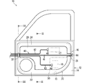
- FIG. 1 is a schematic side view showing a door in which a door wiring module according to an embodiment is incorporated.
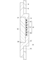
- FIG. 2 is a sectional view taken along line II-II of FIG.
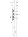
- FIG. 3 is a sectional view taken along the line III-III in FIG.
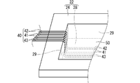
- FIG. 4 is a schematic perspective view showing a portion where the wiring member extends outward from the door surface member.
- FIG. 5 is a schematic perspective view showing a portion where the wiring member extends outward from the door surface member.
- FIG. 6 is an explanatory view showing a method for manufacturing a door wiring module according to the embodiment.
- the door wiring module and the method for manufacturing the door wiring module of the present disclosure are as follows. (1) A door surface member incorporated into a door panel of a vehicle, a wiring member disposed on a main surface of the door surface member, and the main surface and the wiring member of the door surface member. A holding member that covers at least the main surface of the door surface member while directly covering and holds the wiring member in a state of being disposed on the main surface of the door surface member. A wiring module for a door provided. The wiring member can be attached to the door surface member by the holding member that is directly joined to the door surface member. A novel technique for attaching a door wiring member to a door surface member can be provided.
- the planar member for a door is a planar member whose dimension in the thickness direction is smaller than the dimension in the surface direction.
- the wiring member is accommodated in a holding groove formed in the main surface of the door surface member. This is because the holding member can prevent the wiring member from coming off the holding groove.
- the wiring member includes a plurality of electric wires, a plurality of the holding grooves are formed in parallel in the door surface member, and the electric wires are housed in the holding grooves one by one. This is because the electric wires can be held in parallel. This is also because the holding member can be made thin.
- the door surface member includes a wall portion that partitions an area where the holding member is provided, and an outer edge of the holding member is in contact with the wall portion. This is because it is possible to prevent the resin from leaking when the resin is injected to form the holding member.
- the holding member is made of foamed resin and also functions as a soundproof material. This is because it is not necessary to separately provide a member for fixing the wiring member and a soundproof material.
- the holding member may entirely cover at least a portion of the main surface where the wiring member is disposed. This is because the wiring member arranged on the main surface can be held over the entire length.
- a step of disposing a wiring member on a main surface of a door surface member incorporated into a vehicle door panel and (b) the step After (a), the step of injecting a softened resin material onto the main surface and the wiring member of the planar member for door and directly bonding the resin material to at least the main surface is manufactured.
- the wiring member can be attached to the door surface member by directly joining the injected resin to the door surface member.
- FIG. 1 is a schematic side view showing a door 10 in which a door wiring module 20 according to the embodiment is incorporated.
- FIG. 2 is a sectional view taken along line II-II of FIG.
- FIG. 3 is a sectional view taken along the line III-III in FIG.
- FIG. 4 is a schematic perspective view showing a portion where the wiring member 40 extends outward from the door surface member 22.
- FIG. 5 is a schematic perspective view showing a portion where the wiring member 40 extends outward from the door surface member 22.
- FIG. 6 is an explanatory view showing a method of manufacturing the door wiring module 20 according to the embodiment. Note that, in FIG. 1, the holding member 50 that covers the wiring member 40 is shown by a chain double-dashed line.
- the door 10 is formed in a flat shape as a whole, and is a portion that can be opened and closed so as to partition the inside and outside of the vehicle in the vehicle. It is assumed that the door 10 is a driver side door, a passenger side door, a rear seat door, or the like.
- the door 10 includes a door panel 12 and a door wiring module 20.
- the door panel 12 includes an outer panel (not shown) and an inner panel 14.
- the outer panel is a portion that is provided on a portion of the door 10 that faces the outside of the vehicle, and constitutes the exterior of the vehicle together with the body.
- the inner panel 14 is provided on the vehicle compartment side of the outer panel.
- a space for accommodating a window or the like is usually formed between the inner panel 14 and the outer panel.
- a window exposed to the rainwater environment is housed in the space, and a slit-shaped opening through which the window enters and exits is formed above the space. Therefore, the space is a space where water may enter. Further, since the space is a space that may be connected to the external space, it is also a space in which wind noise or the like from the outside may enter.
- the inner panel 14 is provided with an opening 15 for accessing the space when the door 10 is manufactured, maintained, or the like. It is preferable that the opening 15 is closed during normal use of the vehicle. Therefore, the door wiring module 20 is attached so as to close the opening 15.
- the door wiring module 20 includes a door surface member 22, a wiring member 40, and a holding member 50.
- the wiring member 40 is held on the door surface member 22 by a holding member 50. Therefore, when the door surface member 22 is incorporated in the door 10, the wiring member 40 is also incorporated in the door 10.
- the door surface member 22 is a member incorporated between the door panel 12 and the design trim (not shown) in the vehicle door 10.
- the door planar member 22 is not particularly limited as long as it is a member that is incorporated between the door panel 12 and the design trim in the vehicle door 10, and various planar members can be used. In the following description, it is assumed that the door surface member 22 is an inner trim.
- the door 10 in this example further includes a design trim.
- the design trim is a portion that is provided in a portion of the door 10 that faces the inside of the vehicle, and forms an interior view of the vehicle.
- a door handle, an operation unit of an in-vehicle device, or the like is attached to the design trim.
- the door surface member 22 is provided together with the inner panel 14 as a member that completely separates the vehicle interior space and the external space.
- the door planar member 22 is a planar member.
- the term "planar member” as used herein refers to a member having a two-dimensionally spread thickness dimension that is smaller than the dimension in the plane direction (two directions orthogonal to the thickness direction), and is not necessarily flat in the front-back direction (thickness direction). It is not necessary to be, and unevenness may occur in the front and back directions.
- the door surface member 22 includes a main plate portion 24 and an accommodation space forming portion 28.
- the door surface member 22 is attached to the inner panel 14 by screwing, locking structure or the like in a state of being located at a predetermined position where the opening member 15 of the inner panel 14 is closed.
- the main plate portion 24 is a portion that spreads in a plate shape with a size that can close the opening 15.
- a speaker mounting hole 25 for mounting a speaker is formed in the main plate portion 24. It is not essential that the speaker mounting hole 25 is formed in the door surface member 22.
- a speaker mounting hole may be formed in the inner panel 14, and the door surface member 22 may be configured to be mounted in a region other than the portion where the speaker is mounted in the inner panel 14.
- the accommodation space forming portion 28 is formed in a container shape that is open to one main surface side (vehicle compartment side) of the main plate portion 24 and projects to the other main surface side (outside) of the main plate portion 24.
- the accommodation space forming portion 28 is formed in a container shape smaller than the opening 15.
- the accommodation space forming portion 28 is disposed inside the opening 15 in a state in which the door surface member 22 is fitted into the opening 15 of the inner panel 14. Further, a space between the opening edge portion of the accommodation space forming portion 28 and the peripheral edge portion of the opening 15 is closed by the main plate portion 24. For example, if a portion of the peripheral portion of the main plate portion 24 that overlaps the inner panel 14 is screwed to the inner panel 14 with a screw or the like, the gap between them can be closed as much as possible.
- a part or all of the electric components 16, 17, and 18 incorporated in the door 10 can be incorporated in the accommodation space forming portion 28 of the planar member 22 for door.
- electric components 17 and 18 are incorporated.
- a motor for opening and closing a window, an actuator for locking and unlocking the door 10 various switches, and the like are assumed.
- the planar member 22 for a door has a holding groove 30 formed on the main surface thereof, in which the wiring member 40 is accommodated.
- the holding groove 30 holds at least a part of the wiring member 40 along the extending direction.
- the wiring member 40 is housed and held in the holding groove 30, the wiring member 40 is in a state of being wired and held by the door surface member 22.
- the holding groove 30 is formed according to the wiring form of the wiring member 40.
- the holding groove 30 is formed in both the main plate portion 24 and the accommodation space forming portion 28, but it may be formed only in the main plate portion 24 or only in the accommodation space forming portion 28. In some cases,
- the holding groove 30 is formed to be the same as or larger than the electric wires 41, 42, 43.
- the entire periphery of the electric wires 41, 42, 43 is contained in the holding groove 30.
- the holding groove 30 may be formed smaller than the electric wires 41, 42, 43. In this case, part of the electric wires 41, 42, 43 may protrude from the opening of the holding groove 30.
- the door surface member 22 preferably has rigidity that makes it difficult to bend in the front and back directions. Thereby, when the planar member 22 for a door is assembled to the door panel 12, the edges and the like are less likely to bend and are easily held in a spread shape, which facilitates the assembly.
- the door surface member 22 is formed with higher rigidity than the holding member 50.
- the door surface member 22 is, for example, a member formed by molding using resin or metal as a material.
- the door surface member 22 may be formed by pouring a molten material into a mold, or may be formed by press-molding a plate material using the mold.
- the wiring member 40 is electrical wiring provided on the door 10 and connected to the electric components 16, 17, and 18 incorporated in the door 10.
- the wiring member 40 of the door 10 is normally connected to the vehicle on the hinge side of the door 10, and branches off from the front side of the door 10 toward the rear side to be connected to various electric components 16, 17, and 18.
- the wiring member 40 includes a plurality of electric wires 41, 42, 43.
- As the electric wires 41, 42, 43 a coated electric wire in which a coating is formed around a core wire made of a conductor can be used.
- the core wire may be a single core wire or a twisted wire.
- the plurality of electric wires 41, 42, 43 are gathered in parallel at one end side of each.
- One end of the plurality of electric wires 41, 42, 43 extends from the door 10 from the hinge side of the door 10 in a bundled state, is guided into the vehicle body, and is introduced into the vehicle body via a common connector or the like. It is supposed to be connected to another connector.
- the electric wire 41 extends the longest with respect to the electric wires 42 and 43, and the electric wires 42 and 43 branch at an intermediate portion in the extending direction of the electric wire 41.
- Connectors 44, 45, 46 are attached to the other ends of the electric wires 41, 42, 43, respectively.
- the electric wires 41, 42, 43 are connected to the electric components 16, 17, 18 via the connectors 44, 45, 46.
- the electric wires 41, 42, 43 are individually held in the plurality of holding grooves 30.
- the plurality of holding grooves 30 are formed in parallel in a number corresponding to the plurality of electric wires 41, 42, 43.
- the holding groove 30 also branches.
- the electric wire 41 includes a front main surface of the main plate portion 24, a front main surface of the main plate portion 24, a bottom main surface of the accommodation space forming portion 28, and a rear side of the main plate portion 24 from the vertical middle portion of the front edge portion of the main plate portion 24. It is held along a fixed path from the main surface of the main plate portion 24 to the intermediate portion in the up-down direction of the rear edge portion.
- the electric wire 42 is on the upper side of the electric wire 41 and extends from the vertical middle portion of the front edge portion of the main plate portion 24 to the main surface of the bottom of the accommodation space forming portion 28 via the front main surface of the main plate portion 24. Hold along the path.
- the electric wire 43 is below the electric wire 41 and extends from the vertical middle portion of the front edge of the main plate portion 24 to the main surface of the bottom of the accommodation space forming portion 28 via the front main surface of the main plate portion 24. It is held along a fixed path.
- the electric wire 41 extends from the rear end of the door surface member 22 and is connected to the electric component 16.
- the electric component 16 is a component incorporated in the rear portion of the door 10, and is assumed to be, for example, a door lock and unlock motor.
- the electric wires 42 and 43 branch off from the electric wire 41 inside the accommodation space forming portion 28 and are connected to the electric components 17 and 18 inside the accommodation space forming portion 28. Although the electric wire 42 and the electric wire 43 branch at the same position in the middle portion in the extending direction of the electric wire 41, they may branch at different positions.
- the plurality of electric wires 41, 42, 43 are individually housed in the holding groove 30, but even if all of the plurality of electric wires 41, 42, 43 are housed and held in the common holding groove. Good. Further, the plurality of electric wires 41, 42, 43 are divided into a plurality of groups, and the holding grooves are formed in the number corresponding to the plurality of groups, and the plurality of electric wires 41, 42, 43 are arranged in a plurality of groups. It may be housed and held in the holding groove.
- the holding member 50 is a member that holds the wiring member 40 in a state of being arranged on the main surface of the door surface member 22.
- the holding member 50 is formed so as to cover the main surface of the door surface member 22 and the wiring member 40 and to be directly bonded to at least the main surface of the door surface member 22.
- the state of being directly bonded is a state of being directly bonded without an intervening substance such as an adhesive.
- the holding member 50 and the electric wires 41, 42, 43 may or may not be in contact with each other.
- the holding member 50 and the electric wires 41, 42, 43 may be directly joined to each other at a contact portion.
- the holding member 50 and the door surface member 22 are wholly directly joined at the contact portions.
- the holding member 50 is made of, for example, a foamed resin such as urethane foam.
- the holding member 50 may be formed of a resin such as a resin that is not a foamed resin (referred to as a non-foamed resin).
- the holding member 50 may be a single layer or a plurality of layers made of the same material.
- the holding member 50 also serves as a soundproof material.
- the soundproof material is a member that reduces sound.
- the soundproof material may have a function as a sound absorbing material, or may have a function as a sound insulating material.
- the sound absorbing material has a space when viewed in the cross section in the thickness direction.
- the sound absorbing material reduces reflection of sound as much as possible, for example, by absorbing incident sound energy.
- the holding member 50 is made of foamed resin such as urethane foam
- the holding member 50 can also serve as a sound absorbing material.
- the sound insulation material has no space when viewed in the cross section in the thickness direction.
- the sound insulating material shields sound as much as possible by absorbing or reflecting sound energy.
- the holding member 50 when the holding member 50 is formed of a resin such as a resin that is not a foamed resin (referred to as a non-foamed resin), the holding member 50 can also serve as a sound insulating material.
- the holding member 50 may be formed in a two-layer structure such as a layer made of a foamed resin and a layer made of a non-foamed resin to have both a function as a sound absorbing material and a function as a sound insulating material.
- the holding member 50 entirely covers at least a portion of the main surface of the door surface member 22 where the wiring member 40 is arranged.
- the term “entire” as used herein means that at least the entire portion of the main surface of the planar member 22 for door where the intermediate portion of the wiring member 40 is disposed is covered.
- the holding member 50 is the main surface of the door planar member 22 except for the end of the wiring member 40 and the portion of the wiring member 40 located at the edge of the door planar member 22. Of these, at least the entire portion where the wiring member 40 is disposed is covered.
- the region covering the wiring member 40 may be set appropriately and may be a part thereof.
- the holding member 50 is provided in the accommodation space forming portion 28 of the door surface member 22.
- the planar member 22 for a door includes a wall portion 29 that partitions an area where the holding member 50 is provided.
- the part of the planar member 22 for the door that constitutes the inner surface of the accommodation space forming part 28 is a wall part 29 that partitions the region where the holding member 50 is provided.
- At least a part of the outer edge of the holding member 50 is in contact with the wall portion 29.
- At least a part of the peripheral edge portion of the holding member 50 extends along the wall portion 29.
- the wall portion 29 may not be formed in the door surface member 22. Further, the outer edge portion of the holding member 50 may not reach the wall portion 29.
- the electric component 17 mounted on the door surface member 22 is covered with a holding member 50.
- the electric components 17, 18 assembled on the door surface member 22 may include the electric component 17 covered with the holding member 50.
- the electric component 17 connected to the electric wire 42 before the holding member 50 is formed may be covered with the holding member 50.
- the electric component 18 incorporated on the door surface member 22 is not covered with the holding member 50.
- the electric components 17, 18 assembled on the door surface member 22 may include the electric component 18 not covered with the holding member 50.
- the electric component 18 connected to the electric wire 43 after the holding member 50 is formed is preferably not covered with the holding member 50.
- the electric component that is connected to the electric wire before the holding member is formed may not be covered with the holding member.
- the electric component 18 which is not covered by the holding member 50 is formed by, for example, forming the holding member 50.
- the state in which the resin is not covered by the holding member 50 can be achieved.
- All of the electric components incorporated on the door surface member 22 may be covered with the holding member 50, may not be covered with the holding member 50, or may be covered with the holding member 50.
- An electric component not covered with 50 may coexist.
- the holding member 50 is formed so as to close the opening of the holding groove 30 on the side opposite to the bottom thereof, and suppresses the electric wires 41, 42, 43 from falling out of the holding groove 30. It should be noted that the holding member 50 may or may not enter the holding groove 30. When the holding member 50 enters the holding groove 30, the holding member 50 may fill the entire portion of the holding groove 30 from the opening portion to the bottom portion, or may fill only part of the opening portion side. When the holding member 50 fills only a part of the opening side, the holding members 50 may reach the electric wires 41, 42, 43, or may not reach the electric wires.
- the holding member 50 may hold a portion of the electric wires 41, 42, 43 that is not contained in the holding groove 30. In the case where the holding member 50 holds the electric wires 41, 42, 43 located on the flat surface of the door planar member 22, the holding member at the portion of the holding member 50 that is directly joined to the door planar member 22. It is preferable that the thickness of the layer of 50 that is directly bonded to the door surface member 22 be larger than the thickness of the electric wires 41, 42, 43.
- the holding member 50 there are electric wires 41, 42, 43 extending from the holding member 50.
- One ends of the electric wires 41, 42, 43 are portions extending toward the door hinge.
- One ends of the electric wires 41, 42, 43 extend outward from the front edge of the door surface member 22.
- the other end of the electric wire 41 is connected to the electric component 16 that is not provided on the door surface member 22 in the door 10.
- the other end of the electric wire 41 extends outward from the rear edge of the door surface member 22.
- the other end of the electric wire 43 extends from the holding member 50 inside the wall 29.
- the other end of the electric wire 43 is connected to the electric component 18 after the holding member 50 is formed, so that the other end of the electric wire 43 extends from the holding member 50.
- the thickness dimension of the holding member 50 is not particularly limited as long as the wiring member 40 can be held.
- the holding member 50 also serves as a soundproof material, if the thickness dimension of the holding member 50 is large, the soundproofing performance is improved.
- the thickness dimension of the holding member 50 is the same as the depth dimension (height dimension of the wall portion 29) of the accommodation space forming portion 28.
- the thickness dimension of the holding member 50 may be smaller or larger than the depth dimension (height dimension of the wall portion 29) of the accommodation space forming portion 28.
- the holding member 50 may be formed so as to be the same as or less than the outermost protruding portion of the main surface of the door surface member 22. This is because it is possible to suppress an increase in the thickness dimension of the door wiring module 20.
- the accommodation space forming portion 28 When there is a portion extending from the accommodation space forming portion 28 to the main plate portion 24, such as one end portion of the electric wires 41, 42, 43 or the other end portion of the electric wire 41, from the main surface of the bottom of the accommodation space forming portion 28 to the main plate portion.
- An inclined surface that is inclined more gently than the vertical surface toward the main surface of 24 may be formed, and the electric wire may be disposed in this portion.
- a portion of the electric wires 41, 42, 43 that is not held by the holding member 50 on the main surface of the door surface member 22 may be held by another holding portion or may not be held.
- a retaining portion 32 is formed as a holding portion for holding the electric wires 41, 42, 43 housed in the holding groove 30.
- the retaining portion 32 is a portion that is formed so as to narrow or close the opening 15 and suppresses the electric wires 41, 42, 43 from coming off from the opening 15.
- the retaining portion 32 is, for example, a portion formed by crushing a protruding portion 33 formed so as to protrude to the side opposite to the bottom of the holding groove 30 at the periphery of the opening opposite to the bottom. is there.
- the heating member 60 is pressed against the protruding portion 33, and the protruding portion 33 is melted by heat and crushed.
- the manufacturing method of the door wiring module 20 includes the following steps (a) and (b).
- the step (a) is a step of disposing the wiring member 40 on the main surface of the door surface member 22 incorporated in the vehicle door panel 12. This brings the wiring member 40 into a desired wiring state.
- the softened resin material B is injected onto the main surface of the door surface member 22 and the wiring member 40 to directly contact at least the main surface of the door surface member 22. This is the step of joining.
- the resin material B is solidified in a state of being directly bonded to the main surface of the door surface member 22 to become the holding member 50, and the wiring member 40 is placed on the main surface of the door surface member 22. Hold.
- the wiring member 40 is arranged on the main plate portion 24 of the door surface member 22 and the main surface of the accommodation space forming portion 28. At this time, the wiring member 40 is arranged along the holding groove 30 formed in the door surface member 22. The wiring member 40 is held in the holding groove 30 to be maintained in a predetermined wiring state.
- the resin material B is in contact with the main surface of the planar member 22 for a door in a softened state after being injected from the injection port 70, for example.
- the resin material B is a material that can be directly bonded to the main surface of the door planar member 22 by contacting the main surface of the door planar member 22 in a softened state.
- the holding member 50 can also serve as a soundproof material.
- the periphery of the injection area is partitioned by the wall portion 29, the mold and the like.
- the resin material B is suppressed from being injected into a portion where the resin material B is not desired to be injected.
- the portion where the resin material B reaches the wall portion 29, the mold, etc. is the outer edge portion of the holding member 50.
- the portion where the resin material B reaches the wall portion 29 is directly joined to the wall portion 29.
- the viscosity of the resin material B is high, the resin material B may not enter the holding groove 30. Further, when the viscosity of the resin material B is low, the resin material B may enter the holding groove 30.
- the surface of the holding member 50 can be made flat. Further, there may be a mold for covering the upper part of the injection region whose periphery is partitioned by the wall portion 29, the mold or the like. In this case, the surface portion of the holding member 50 can be formed in a shape corresponding to the inner surface shape of the mold that covers.
- the wiring member 40 can be attached to the door planar member 22 by the holding member 50 that is directly joined to the door planar member 22.
- a novel technique for attaching the wiring member 40 for the door 10 to the planar member for the door 10 can be provided.
- the holding member 50 can prevent the wiring member 40 from coming off the groove. Since the plurality of holding grooves 30 are formed, the electric wires 41, 42, 43 can be held in parallel. Further, the protrusion of the electric wires 41, 42, 43 from the holding groove 30 is suppressed, and the holding member 50 can be made thin.
- the door surface member 22 includes a wall portion 29 that partitions an area where the holding member 50 is provided. Since the outer edge of the holding member 50 is in contact with the wall portion 29, the resin material B is injected to form the holding member 50. It is possible to prevent the resin material B from leaking at times.
- the holding member 50 is made of foamed resin and also serves as a soundproof material, it is not necessary to separately provide a member for fixing the wiring member 40 and a soundproof material.
- the holding member 50 entirely covers at least the portion of the main surface on which the wiring member 40 is arranged, the wiring member 40 arranged on the main surface can be held over the entire length.
- the sheet member for door in the door wiring module 20 may be a sheet member assembled to the door 10, and may be, for example, a design trim.
- the holding groove 30 may not be formed in the door surface member 22.
- the electric wires 41, 42, 43 may be arranged so as to overlap each other on the door surface member 22, or may be arranged so as not to overlap each other.
Landscapes
- Engineering & Computer Science (AREA)
- Mechanical Engineering (AREA)
- Physics & Mathematics (AREA)
- Acoustics & Sound (AREA)
- Architecture (AREA)
- Civil Engineering (AREA)
- Structural Engineering (AREA)
- Vehicle Interior And Exterior Ornaments, Soundproofing, And Insulation (AREA)
- Installation Of Indoor Wiring (AREA)
- Automobile Manufacture Line, Endless Track Vehicle, Trailer (AREA)
Abstract
ドア用の面状部材にドア用の配線部材を取付けるための新規な技術を提供することを目的とする。ドア用配線モジュールは、車両のドアパネルに組込まれるドア用面状部材と、前記ドア用面状部材における主面上に配設された配線部材と、前記ドア用面状部材における前記主面及び前記配線部材を覆いつつ少なくとも前記ドア用面状部材における前記主面と直接接合するように形成されて前記配線部材を前記ドア用面状部材における主面上に配設された状態に保持する保持部材と、を備える。
Description
本開示は、ドア用配線モジュール及びドア用配線モジュールの製造方法に関する。
特許文献1は、ドアにドア用のワイヤーハーネスを組付ける技術を開示している。特許文献1では、ワイヤーハーネスが取付けられたドアトリムをドアパネルに組付けている。
特許文献1では、ドア用ハーネスに取付けられたバンドがネジによってトリムパネルに固定されることによって、ドア用ハーネスがドアトリムに取付けられている。
ドア用の面状部材にドア用の配線部材を取付けるための新規な技術を提供することを目的とする。
本開示のドア用配線モジュールは、車両のドアパネルに組込まれるドア用面状部材と、前記ドア用面状部材における主面上に配設された配線部材と、前記ドア用面状部材における前記主面及び前記配線部材を覆いつつ少なくとも前記ドア用面状部材における前記主面と直接接合するように形成されて前記配線部材を前記ドア用面状部材における主面上に配設された状態に保持する保持部材と、を備える、ドア用配線モジュールである。
本開示によれば、ドア用の面状部材にドア用の配線部材を取付けるための新規な技術を提供することができる。
[本開示の実施形態の説明]
最初に本開示の実施態様を列記して説明する。
本開示のドア用配線モジュール及びドア用配線モジュールの製造方法は、次の通りである。
(1)車両のドアパネルに組込まれるドア用面状部材と、前記ドア用面状部材における主面上に配設された配線部材と、前記ドア用面状部材における前記主面及び前記配線部材を覆いつつ少なくとも前記ドア用面状部材における前記主面と直接接合するように形成されて前記配線部材を前記ドア用面状部材における主面上に配設された状態に保持する保持部材と、を備える、ドア用配線モジュールである。
ドア用面状部材と直接接合される保持部材によって、配線部材をドア用面状部材に取付けることができる。ドア用の面状部材にドア用の配線部材を取付けるための新規な技術を提供することができる。
ここでドア用面状部材とは厚み方向の寸法が面方向の寸法よりも小さい面状の部材である。
(2)前記配線部材は前記ドア用面状部材の前記主面に形成された保持溝に収まっていることが好ましい。保持部材によって、配線部材が保持溝から抜けることを抑制できるからである。
(3)前記配線部材は複数の電線を含み、前記ドア用面状部材には、前記保持溝が並列状態で複数形成され、前記電線が1本ずつ前記保持溝に収まっていると良い。電線を並列状態で保持することができるからである。また保持部材を薄くすることができるからである。
(4)前記ドア用面状部材は、前記保持部材が設けられる領域を仕切る壁部を含み、前記保持部材の外縁が前記壁部に接していると良い。樹脂を注入して保持部材を形成する時に樹脂が漏れることを抑制することができるからである。
(5)前記保持部材は発泡樹脂を材料として形成されて防音材を兼ねると良い。配線部材を固定する部材と、防音材とを別に設けずに済むからである。
(6)前記保持部材は、前記主面のうち少なくとも前記配線部材が配設された部分を全面的に覆っているとよい。主面上に配設された配線部材を全長に亘って保持することができるからである。
(7)また、本開示のドア用配線モジュールの製造方法は、(a)車両のドアパネルに組込まれるドア用面状部材における主面上に配線部材を配設する工程と、(b)前記工程(a)の後で、前記ドア用面状部材における前記主面及び前記配線部材上に軟化した樹脂材料を注入して少なくとも前記主面と直接接合させる工程と、を備えるドア用配線モジュールの製造方法である。注入した樹脂がドア用面状部材と直接接合されることによって、配線部材をドア用面状部材に取付けることができる。ドア用の面状部材にドア用の配線部材を取付けるための新規な技術を提供することができる。
最初に本開示の実施態様を列記して説明する。
本開示のドア用配線モジュール及びドア用配線モジュールの製造方法は、次の通りである。
(1)車両のドアパネルに組込まれるドア用面状部材と、前記ドア用面状部材における主面上に配設された配線部材と、前記ドア用面状部材における前記主面及び前記配線部材を覆いつつ少なくとも前記ドア用面状部材における前記主面と直接接合するように形成されて前記配線部材を前記ドア用面状部材における主面上に配設された状態に保持する保持部材と、を備える、ドア用配線モジュールである。
ドア用面状部材と直接接合される保持部材によって、配線部材をドア用面状部材に取付けることができる。ドア用の面状部材にドア用の配線部材を取付けるための新規な技術を提供することができる。
ここでドア用面状部材とは厚み方向の寸法が面方向の寸法よりも小さい面状の部材である。
(2)前記配線部材は前記ドア用面状部材の前記主面に形成された保持溝に収まっていることが好ましい。保持部材によって、配線部材が保持溝から抜けることを抑制できるからである。
(3)前記配線部材は複数の電線を含み、前記ドア用面状部材には、前記保持溝が並列状態で複数形成され、前記電線が1本ずつ前記保持溝に収まっていると良い。電線を並列状態で保持することができるからである。また保持部材を薄くすることができるからである。
(4)前記ドア用面状部材は、前記保持部材が設けられる領域を仕切る壁部を含み、前記保持部材の外縁が前記壁部に接していると良い。樹脂を注入して保持部材を形成する時に樹脂が漏れることを抑制することができるからである。
(5)前記保持部材は発泡樹脂を材料として形成されて防音材を兼ねると良い。配線部材を固定する部材と、防音材とを別に設けずに済むからである。
(6)前記保持部材は、前記主面のうち少なくとも前記配線部材が配設された部分を全面的に覆っているとよい。主面上に配設された配線部材を全長に亘って保持することができるからである。
(7)また、本開示のドア用配線モジュールの製造方法は、(a)車両のドアパネルに組込まれるドア用面状部材における主面上に配線部材を配設する工程と、(b)前記工程(a)の後で、前記ドア用面状部材における前記主面及び前記配線部材上に軟化した樹脂材料を注入して少なくとも前記主面と直接接合させる工程と、を備えるドア用配線モジュールの製造方法である。注入した樹脂がドア用面状部材と直接接合されることによって、配線部材をドア用面状部材に取付けることができる。ドア用の面状部材にドア用の配線部材を取付けるための新規な技術を提供することができる。
[本開示の実施形態の詳細]
本開示のドア用配線モジュール及びその製造方法の具体例を、以下に図面を参照しつつ説明する。なお、本発明はこれらの例示に限定されるものではなく、請求の範囲によって示され、請求の範囲と均等の意味および範囲内でのすべての変更が含まれることが意図される。
本開示のドア用配線モジュール及びその製造方法の具体例を、以下に図面を参照しつつ説明する。なお、本発明はこれらの例示に限定されるものではなく、請求の範囲によって示され、請求の範囲と均等の意味および範囲内でのすべての変更が含まれることが意図される。
[実施形態]
以下、実施形態に係るドア用配線モジュール及びその製造方法について説明する。図1は、実施形態にかかるドア用配線モジュール20が組込まれたドア10を示す概略側面図である。図2は図1のII-II線に沿って切断した断面図である。図3は図1のIII-III線に沿って切断した断面図である。図4は配線部材40がドア用面状部材22から外方に延びる部分を示す概略斜視図である。図5は配線部材40がドア用面状部材22から外方に延びる部分を示す概略斜視図である。図6は実施形態にかかるドア用配線モジュール20の製造方法を示す説明図である。なお、図1では、配線部材40を覆う保持部材50が二点鎖線で示されている。
以下、実施形態に係るドア用配線モジュール及びその製造方法について説明する。図1は、実施形態にかかるドア用配線モジュール20が組込まれたドア10を示す概略側面図である。図2は図1のII-II線に沿って切断した断面図である。図3は図1のIII-III線に沿って切断した断面図である。図4は配線部材40がドア用面状部材22から外方に延びる部分を示す概略斜視図である。図5は配線部材40がドア用面状部材22から外方に延びる部分を示す概略斜視図である。図6は実施形態にかかるドア用配線モジュール20の製造方法を示す説明図である。なお、図1では、配線部材40を覆う保持部材50が二点鎖線で示されている。
ドア10は、全体として偏平な形状に形成されており、車両において車室内と車室外とを仕切るように開閉可能に設けられる部分である。ドア10は、運転席側ドア、助手席側ドア、後部座席用ドアである場合等が想定される。ドア10は、ドアパネル12と、ドア用配線モジュール20とを備える。
ドアパネル12は、アウターパネル(図示省略)と、インナーパネル14とを備える。アウターパネルは、ドア10のうち車両外側に面する部分に設けられ、ボディと共に車両の外観を構成する部分である。インナーパネル14は、アウターパネルの車室側に設けられている。インナーパネル14及びアウターパネルの間には、通常、ウインドウなどを収納ための空間が形成されている。当該空間には、雨水環境に曝されるウインドウが収容され、また、当該空間の上方には、ウインドウが出入りするスリット状の開口が形成されている。このため、当該空間は、水が侵入する可能性がある空間である。また、当該空間は、外部空間と繋がる可能性のある空間であるため、外部からの風切り音等が侵入する恐れがある空間でもある。一方、インナーパネル14には、ドア10の製造時、メンテナンス時等に上記空間にアクセスするための開口15が設けられている。この開口15は車両の通常使用時等には塞がれることが好ましい。そこで、当該開口15を閉じるようにドア用配線モジュール20が取付けられる。
ドア用配線モジュール20は、ドア用面状部材22と、配線部材40と、保持部材50と、を備える。配線部材40は保持部材50によってドア用面状部材22に保持されている。このため、ドア用面状部材22がドア10に組込まれることによって、配線部材40も併せてドア10に組み込まれる。
本例では、ドア用面状部材22は、車両のドア10においてドアパネル12と意匠トリム(図示省略)との間に組込まれる部材である。ドア用面状部材22は、車両のドア10においてドアパネル12と意匠トリムとの間に組込まれる部材であれば特に限定されるものではなく、種々の面状部材を用いることができる。以下では、ドア用面状部材22がインナートリムであるものとして説明する。
なお本例におけるドア10は、意匠トリムをさらに備える。意匠トリムは、ドア10のうち車室内側に面する部分に設けられ、車両の内観を構成する部分である。意匠トリムには例えば、ドアハンドル、車載機器の操作部等が取付けられる。
ドア用面状部材22は、インナーパネル14と共に車室空間と外部空間とをより完全に仕切る部材として設けられている。ドア用面状部材22は、面状の部材である。なお、ここでいう面状の部材とは、厚み寸法が、面方向(厚み方向に直交する2方向)の寸法よりも小さい2次元的に広がる部材を言い、必ずしも表裏方向(厚み方向)に平坦である必要はなく、表裏方向に凹凸が生じていてもよい。
ドア用面状部材22は、主板部24と、収容空間形成部28とを含む。ドア用面状部材22がインナーパネル14の開口15を塞ぐ所定位置に位置する状態で、ネジ止、係止構造等によってインナーパネル14に組付けられる。
主板部24は、開口15を塞ぐことができる程度の大きさで板状に広がる部分である。なお、主板部24には、スピーカを組込むためのスピーカ組込孔25が形成されている。ドア用面状部材22にスピーカ組込孔25が形成されていることは必須ではない。例えば、インナーパネル14にスピーカ組込孔が形成されており、ドア用面状部材22は、インナーパネル14に対してスピーカが組込まれる部分を除く領域に組込まれる構成であってもよい。収容空間形成部28は、主板部24の一方主面側(車室側)に開口すると共に、主板部24の他方主面側(外側)に突出する容器状に形成されている。収容空間形成部28は、開口15よりも小さい容器状に形成されている。ドア用面状部材22がインナーパネル14の開口15に嵌め込まれた状態で、収容空間形成部28が開口15の内側に配設される。また、収容空間形成部28の開口縁部と開口15の周縁部との間が、主板部24によって塞がれる。例えば、主板部24の周縁部のうちインナーパネル14に重なる部分がネジ等によってインナーパネル14にネジ止されれば、それらの間の隙間を可及的に塞ぐことができる。
ドア用面状部材22の収容空間形成部28等には、ドア10に組込まれる電気部品16、17、18の一部又は全部を組込むことができる。ここでは電気部品17、18が組込まれている。電気部品17、18としては、ウインドウを開閉するモータ、ドア10をロック及びアンロックするためのアクチュエーター、各種スイッチであること等が想定される。
ドア用面状部材22には、その主面上に配線部材40が収容される保持溝30が形成されている。保持溝30は、配線部材40の延在方向に沿った少なくとも一部を保持する。配線部材40が保持溝30に収容保持されることによって、配線部材40がドア用面状部材22に配線されて保持された状態となる。保持溝30は、配線部材40の配線形態に応じて形成されている。ここでは主板部24と収容空間形成部28との両方に保持溝30が形成されているが、主板部24のみに形成されている場合もあり得るし、収容空間形成部28のみに形成されている場合もあり得る。保持溝30は電線41、42、43と同じかそれよりも大きく形成されている。このため、電線41、42、43の周囲全体が保持溝30内に収まっている。もっとも保持溝30は電線41、42、43よりも小さく形成されていてもよい。この場合、電線41、42、43の一部が保持溝30の開口部から突出していてもよい。
ドア用面状部材22は、表裏方向に曲げ困難な剛性を有しているとよい。これにより、ドア用面状部材22がドアパネル12に組付けられるときに、縁部などが曲がりにくく、広がった形状に保たれやすいことによって、組付けが容易となる。例えば、ドア用面状部材22は、保持部材50よりも高剛性に形成されている。ドア用面状部材22は、例えば樹脂又は金属を材料として金型成型された部材である。ドア用面状部材22は、金型内に溶融材料が流し込まれて成型されたものでもよいし、板材が金型を用いたプレス成型されて成型されたものであってもよい。
配線部材40は、ドア10に設けられ、当該ドア10に組込まれた電気部品16、17、18に接続される電気的な配線である。ドア10の配線部材40は、通常、ドア10のヒンジ側で車両と接続されており、ドア10の前側から後側に向う際に分岐して各種電気部品16、17、18に接続される。ここでは、配線部材40は、複数の電線41、42、43を含む。電線41、42、43としては、導体で構成された芯線の周囲に被覆が形成された被覆電線を用いることができる。芯線は、単芯線であってもよいし、撚り合せ線であってもよい。
ここでは、複数の電線41、42、43は、それぞれの一端側では並列状態に集合されている。複数の電線41、42、43の一端部は、例えば、束ねられた状態でドア10のヒンジ側から当該ドア10から延出し、車両本体内に導かれ、共通コネクタ等を介して車両本体内の他のコネクタに接続されることが想定される。電線41は、電線42、43に対して最も長く延在し、電線42、43は、電線41の延在方向中間部で分岐している。電線41、42、43のそれぞれの他端部には、コネクタ44、45、46が取付けられている。電線41、42、43は、当該コネクタ44、45、46を介して電気部品16、17、18に接続される。
電線41、42、43は、複数の保持溝30内に個別に保持されている。ここでは、複数の保持溝30は、複数の電線41、42、43に応じた数、並列状態で形成されている。電線41、42、43の分岐に伴い、保持溝30も分岐している。
より具体的には、電線41は、主板部24の前縁部の上下方向中間部から当該主板部24の前側の主面、収容空間形成部28の底の主面、主板部24の後側の主面を経由して、主板部24の後縁部の上下方向中間部に至る一定経路に沿って保持されている。電線42は、電線41の上側で、主板部24の前縁部の上下方向中間部から当該主板部24の前側の主面を経由して収容空間形成部28の底の主面までに至る一定経路に沿って保持されている。電線43は、電線41の下側で、主板部24の前縁部の上下方向中間部から当該主板部24の前側の主面を経由して収容空間形成部28の底の主面までに至る一定経路に沿って保持されている。
電線41は、ドア用面状部材22の後端部から延出して電気部品16に接続される。電気部品16は、ドア10の後部に組込まれる部品であり、例えば、ドアロック及びアンロック用モータなどが想定される。電線42、43は、収容空間形成部28内で電線41と分岐し、当該収容空間形成部28内の電気部品17、18に接続される。なお、電線42と、電線43とは電線41の延在方向中間部において同じ位置で分岐しているが、異なる位置で分岐していてもよい。
本実施形態では、複数の電線41、42、43が、個別に保持溝30に収容されているが、複数の電線41、42、43の全てが共通する保持溝に収容されて保持されてもよい。また、複数の電線41、42、43が複数のグループに分けられると共に、当該複数のグループに応じた数の保持溝が形成され、複数の電線41、42、43が複数のグループ毎に複数の保持溝に収容されて保持されてもよい。
保持部材50は、配線部材40をドア用面状部材22における主面上に配設された状態に保持する部材である。保持部材50は、ドア用面状部材22における主面及び配線部材40を覆いつつ少なくともドア用面状部材22における主面と直接接合するように形成されている。ここで直接接合された状態とは、接着剤等の介在物を介さずに直接くっついている状態を言う。保持部材50と電線41、42、43とは、接していてもよいし、接していなくてもよい。保持部材50と電線41、42、43とが接している部分においては直接接合されていてもよい。
保持部材50とドア用面状部材22とは、接する部分が全体的に直接接合している。保持部材50は、例えば、ウレタンフォーム等の発泡樹脂を材料として形成される。保持部材50は、発泡樹脂でない樹脂(非発泡樹脂と称する)などの樹脂を材料として形成されていてもよい。保持部材50は、同一材料による一層であってもよいし、複数層であってもよい。
保持部材50は防音材を兼ねる。防音材は、音を減らす部材である。防音材は、吸音材としての機能を有するものであってもよいし、遮音材としての機能を有するものであってもよい。吸音材は、厚み方向の断面を見て空間があるものである。吸音材は、例えば、入射した音エネルギーを吸収等することで、音の反射をなるべく少なくする。例えば、保持部材50がウレタンフォーム等の発泡樹脂を材料として形成されることによって、保持部材50が吸音材を兼ねることができる。遮音材は、厚み方向の断面を見て空間がないものである。遮音材は、例えば、音エネルギーを吸収したり反射したりすることで音をなるべく遮る。例えば、保持部材50が発泡樹脂でない樹脂(非発泡樹脂と称する)などの樹脂を材料として形成されることによって、保持部材50が遮音材を兼ねることができる。保持部材50は、発泡樹脂を材料とした層と、非発泡樹脂を材料とした層との2層構造などに形成されて吸音材としての機能と遮音材としての機能を兼ね備えていてもよい。
保持部材50は、ドア用面状部材22における主面のうち少なくとも配線部材40が配設された部分を全面的に覆っている。なおここでいう全面的とは、ドア用面状部材22における主面のうち少なくとも配線部材40の中間部が配設された部分全体を覆っていることを言う。図1に示す例では、保持部材50は、配線部材40における端部及び配線部材40のうちドア用面状部材22の縁部に位置する部分を除いて、ドア用面状部材22における主面のうち少なくとも配線部材40が配設された部分全体を覆っている。もっとも保持部材50は、配線部材40を保持可能であれば配線部材40を覆う領域は適宜設定されていればよく、一部であってもよい。
保持部材50は、ドア用面状部材22における収容空間形成部28に設けられている。ドア用面状部材22は、保持部材50が設けられる領域を仕切る壁部29を含む。ここでは、ドア用面状部材22において収容空間形成部28の内面を構成する部分が、保持部材50が設けられる領域を仕切る壁部29とされている。保持部材50の外縁の少なくとも一部が壁部29に接している。保持部材50の周縁部の少なくとも一部は、壁部29に沿って延びている。もっともドア用面状部材22において壁部29が形成されていなくてもよい。また保持部材50の外縁部が壁部29に達していなくてもよい。
ドア用面状部材22上に組み込まれる電気部品17は、保持部材50で覆われている。このようにドア用面状部材22上に組み込まれる電気部品17、18には保持部材50で覆われている電気部品17があってもよい。例えば保持部材50が形成されるより先に電線42と接続される電気部品17については、保持部材50で覆われていてもよい。ドア用面状部材22上に組み込まれる電気部品18は、保持部材50で覆われていない。このようにドア用面状部材22上に組み込まれる電気部品17、18には保持部材50で覆われていない電気部品18があってもよい。例えば、保持部材50が形成されるより後に電線43と接続される電気部品18については、保持部材50で覆われていないとよい。もちろん、保持部材が形成されるより先に電線と接続される電気部品について保持部材で覆われていなくてもよい。ドア用面状部材22上に組み込まれる電気部品の中に保持部材50で覆われていない電気部品18がある場合、この保持部材50によって覆われていない電気部品18は例えば、保持部材50の形成時に周囲に樹脂が入らないように金型等で仕切られていることによって、保持部材50で覆われていない状態とすることができる。ドア用面状部材22上に組み込まれる電気部品は、すべて保持部材50で覆われてもよいし、すべて保持部材50で覆われなくてもよいし、保持部材50で覆われる電気部品と保持部材50で覆われない電気部品とが併存していてもよい。
ここでは、保持部材50は、保持溝30のうちその底とは反対側の開口部を塞ぐように形成されて、保持溝30内の電線41、42、43の抜けを抑制する。なお保持部材50は、保持溝30に入り込んでいてもよいし、保持溝30に入り込んでいなくてもよい。保持部材50は、保持溝30に入り込む場合、保持溝30の開口部から底部まで全体を満たしていてもよいし、開口部側の一部のみを満たしていてもよい。保持部材50は、開口部側の一部のみを満たしている場合、電線41、42、43まで達していてもよいし、達していなくてもよい。
保持部材50は、電線41、42、43のうち保持溝30に収まっていない部分を保持するものであってもよい。保持部材50がドア用面状部材22における平坦な面上に位置する電線41、42、43を保持する場合、保持部材50のうちドア用面状部材22と直接接合している部分において保持部材50のうちドア用面状部材22と直接接合している層の厚みが電線41、42、43の厚みよりも大きいとよい。
保持部材50の外縁において、保持部材50から延出する電線41、42、43が存在する。電線41、42、43の一方端部は、ドアヒンジに向けて延出する部分である。電線41、42、43の一方端部は、ドア用面状部材22における前縁部から外方に延出する。電線41の他端部は、ドア10において、ドア用面状部材22に設けられない電気部品16に接続される。電線41の他端部は、ドア用面状部材22における後縁部から外方に延出する。電線43の他端部は、壁部29の内部において保持部材50から延出する。例えば電線43の他端部は、保持部材50の形成後に、電気部品18に接続されるため、電線43の他端部が保持部材50から延出している。
保持部材50の厚み寸法は特に限定されるものではなく、配線部材40を保持できればよい。保持部材50が防音材を兼ねる場合、保持部材50における厚み寸法が大きいと、防音性能が高くなる。図2に示す例では、保持部材50における厚み寸法は、収容空間形成部28における深さ寸法(壁部29の高さ寸法)と同じである。もちろん、保持部材50における厚み寸法は、収容空間形成部28における深さ寸法(壁部29の高さ寸法)よりも小さくてもよいし、大きくてもよい。保持部材50は、ドア用面状部材22の主面において最も外側に突出する部分に対してそれと同じかそれよりも突出しないように形成されていてもよい。ドア用配線モジュール20における厚み寸法が大きくなることを抑制できるからである。
電線41、42、43の一方端部、電線41の他端部のように収容空間形成部28から主板部24に延びる部分が存在する場合、収容空間形成部28の底の主面から主板部24の主面に向けて垂直面よりも緩やかに傾斜する傾斜面が形成されて、この部分に電線が配設されていてもよい。また主板部24のうち電線41、42、43が外方に延出する部分では、周囲の部分よりも凹んだ延出用部分26があってもよい。延出用部分26は、保持部材50に覆われていてもよいし、覆われていなくてもよい。
電線41、42、43のうちドア用面状部材22の主面上において、保持部材50によって保持されない部分は、別の保持部によって保持されていてもよいし、保持されていなくてもよい。例えば、保持溝30に収められた電線41、42、43を保持する保持部として、図3に示す例では、抜止部32が形成されている。抜止部32は、開口15を狭くするように或は閉じるように形成されて、開口15から電線41、42、43が抜けることを抑制する部分である。抜止部32は、例えば、保持溝30のうち底とは反対側の開口部周縁部に、当該底とは反対側に突出するように形成された突出部分33が潰されて形成された部分である。突出部分33は、例えば、加熱部材60等が押し当てられて熱によって溶かされて潰される。
<製造方法>
上記ドア用配線モジュール20を製造する方法について説明する。ドア用配線モジュール20の製造方法は、以下の工程(a)、工程(b)を備える。
上記ドア用配線モジュール20を製造する方法について説明する。ドア用配線モジュール20の製造方法は、以下の工程(a)、工程(b)を備える。
工程(a)は、車両のドアパネル12に組込まれるドア用面状部材22における主面上に配線部材40を配設する工程である。これにより、配線部材40が所望の配線状態となる。工程(b)は、工程(a)の後で、ドア用面状部材22における主面及び配線部材40上に軟化した樹脂材料Bを注入して少なくともドア用面状部材22における主面と直接接合させる工程である。工程(b)において、樹脂材料Bがドア用面状部材22における主面と直接接合した状態で固まることによって、上記保持部材50となり、配線部材40をドア用面状部材22における主面上に保持する。
工程(a)に関し、ここではドア用面状部材22における主板部24、収容空間形成部28における主面上に配線部材40を配設する。このとき、ドア用面状部材22に形成された保持溝30に沿って配線部材40を配設していく。配線部材40は、保持溝30に収容保持されることによって所定の配線状態に維持される。
工程(b)に関し、樹脂材料Bは、例えば注入口70から注入された後に軟化した状態でドア用面状部材22における主面と接する。樹脂材料Bは、軟化した状態でドア用面状部材22における主面と接することによって、ドア用面状部材22における主面と直接接合可能な材料である。ここでは樹脂材料Bとして発泡樹脂を用いることによって、保持部材50が防音材を兼ねることができる。
樹脂材料Bの注入時に注入領域の周囲が壁部29、金型等によって仕切られる。これにより、樹脂材料Bを注入させたくない部分に樹脂材料Bが注入することが抑制される。樹脂材料Bが壁部29、金型等に達した部分は、保持部材50における外縁部となる。樹脂材料Bが壁部29に達した部分では、壁部29と直接接合する。また樹脂材料Bの粘度が高い場合などには、樹脂材料Bが保持溝30に入らない場合があり得る。また樹脂材料Bの粘度が低い場合などには、樹脂材料Bが保持溝30に入る場合があり得る。
樹脂材料Bが所定量注入された状態で、その表面部(ドア用面状部材22における主面と接する側とは反対側の面)はならされていてもよいし、ならされていなくてもよい。樹脂材料Bがならされていると、保持部材50における表面部が平坦となることができる。また周囲が壁部29、金型等によって仕切られる注入領域の上部に対して蓋をする金型があってもよい。この場合、保持部材50における表面部は、蓋をする金型の内面形状に応じた形状に形成されうる。
本開示によると、ドア用面状部材22と直接接合される保持部材50によって、配線部材40をドア用面状部材22に取付けることができる。ドア10用の面状部材にドア10用の配線部材40を取付けるための新規な技術を提供することができる。
電線41、42、43が収容される保持溝30が形成されており、保持部材50が保持溝30を覆っているため、保持部材50によって、配線部材40が溝から抜けることを抑制できる。複数の保持溝30が形成されているため、電線41、42、43を並列状態で保持することができる。また保持溝30からの電線41、42、43の突出が抑えられ、保持部材50を薄くすることができる。
ドア用面状部材22は保持部材50が設けられる領域を仕切る壁部29を含み、保持部材50の外縁が壁部29に接しているため、樹脂材料Bを注入して保持部材50を形成する時に樹脂材料Bが漏れることを抑制することができる。
保持部材50は発泡樹脂を材料として形成されて防音材を兼ねるため、配線部材40を固定する部材と、防音材とを別に設けずに済む。
保持部材50は、主面のうち少なくとも配線部材40が配設された部分を全面的に覆っているため、主面上に配設された配線部材40を全長に亘って保持することができる。
[付記]
実施形態では、ドア用配線モジュール20におけるドア用面状部材22がインナートリムである例で説明したが、このことは必須の構成ではない。ドア用配線モジュール20におけるドア用面状部材はドア10に組付けられる面状の部材であればよく、例えば意匠トリムであってもよい。
実施形態では、ドア用配線モジュール20におけるドア用面状部材22がインナートリムである例で説明したが、このことは必須の構成ではない。ドア用配線モジュール20におけるドア用面状部材はドア10に組付けられる面状の部材であればよく、例えば意匠トリムであってもよい。
ドア用面状部材22において保持溝30が形成されていなくてもよい。この場合、ドア用面状部材22上において電線41、42、43は重なるように配線されていてもよいし、重ならないように並んだ状態で配線されていてもよい。
なお、上記実施形態及び各変形例で説明した各構成は、相互に矛盾しない限り適宜組み合わせることができる。
10 ドア
12 ドアパネル
14 インナーパネル
15 開口
16、17、18 電気部品
20 ドア用配線モジュール
22 ドア用面状部材
24 主板部
25 スピーカ組込穴
26 延出用部分
28 収容空間形成部
29 壁部
30 保持溝
32 抜止部
33 突出部分
40 配線部材
41、42、43 電線
44、45、46 コネクタ
50 保持部材
60 加熱部材
70 注入口
B 樹脂材料
12 ドアパネル
14 インナーパネル
15 開口
16、17、18 電気部品
20 ドア用配線モジュール
22 ドア用面状部材
24 主板部
25 スピーカ組込穴
26 延出用部分
28 収容空間形成部
29 壁部
30 保持溝
32 抜止部
33 突出部分
40 配線部材
41、42、43 電線
44、45、46 コネクタ
50 保持部材
60 加熱部材
70 注入口
B 樹脂材料
Claims (7)
- 車両のドアパネルに組込まれるドア用面状部材と、
前記ドア用面状部材における主面上に配設された配線部材と、
前記ドア用面状部材における前記主面及び前記配線部材を覆いつつ少なくとも前記ドア用面状部材における前記主面と直接接合するように形成されて前記配線部材を前記ドア用面状部材における主面上に配設された状態に保持する保持部材と、
を備える、ドア用配線モジュール。 - 請求項1に記載のドア用配線モジュールであって、
前記配線部材は前記ドア用面状部材の前記主面に形成された保持溝に収まっている、ドア用配線モジュール。 - 請求項2に記載のドア用配線モジュールであって、
前記配線部材は複数の電線を含み、
前記ドア用面状部材には、前記保持溝が並列状態で複数形成され、
前記電線が1本ずつ前記保持溝に収まっている、ドア用配線モジュール。 - 請求項1から請求項3のいずれか1項に記載のドア用配線モジュールであって、
前記ドア用面状部材は、前記保持部材が設けられる領域を仕切る壁部を含み、
前記保持部材の外縁が前記壁部に接している、ドア用配線モジュール。 - 請求項1から請求項4のいずれか1項に記載のドア用配線モジュールであって、
前記保持部材は発泡樹脂を材料として形成されて防音材を兼ねる、ドア用配線モジュール。 - 請求項1から請求項5のいずれか1項に記載のドア用配線モジュールであって、
前記保持部材は、前記主面のうち少なくとも前記配線部材が配設された部分を全面的に覆っている、ドア用配線モジュール。 - (a)車両のドアパネルに組込まれるドア用面状部材における主面上に配線部材を配設する工程と、
(b)前記工程(a)の後で、前記ドア用面状部材における前記主面及び前記配線部材上に軟化した樹脂材料を注入して少なくとも前記主面と直接接合させる工程と、
を備える、ドア用配線モジュールの製造方法。
Priority Applications (2)
| Application Number | Priority Date | Filing Date | Title |
|---|---|---|---|
| CN202080011244.3A CN113382890B (zh) | 2019-02-08 | 2020-01-20 | 车门用配线模块及车门用配线模块的制造方法 |
| US17/427,445 US12049177B2 (en) | 2019-02-08 | 2020-01-20 | Door wiring module and method of manufacturing door wiring module |
Applications Claiming Priority (2)
| Application Number | Priority Date | Filing Date | Title |
|---|---|---|---|
| JP2019021185A JP7147607B2 (ja) | 2019-02-08 | 2019-02-08 | ドア用配線モジュール及びドア用配線モジュールの製造方法 |
| JP2019-021185 | 2019-09-24 |
Publications (1)
| Publication Number | Publication Date |
|---|---|
| WO2020162147A1 true WO2020162147A1 (ja) | 2020-08-13 |
Family
ID=71947405
Family Applications (1)
| Application Number | Title | Priority Date | Filing Date |
|---|---|---|---|
| PCT/JP2020/001673 Ceased WO2020162147A1 (ja) | 2019-02-08 | 2020-01-20 | ドア用配線モジュール及びドア用配線モジュールの製造方法 |
Country Status (4)
| Country | Link |
|---|---|
| US (1) | US12049177B2 (ja) |
| JP (1) | JP7147607B2 (ja) |
| CN (1) | CN113382890B (ja) |
| WO (1) | WO2020162147A1 (ja) |
Families Citing this family (4)
| Publication number | Priority date | Publication date | Assignee | Title |
|---|---|---|---|---|
| JP7147620B2 (ja) * | 2019-02-20 | 2022-10-05 | 株式会社オートネットワーク技術研究所 | ドア用配線モジュール |
| KR102858870B1 (ko) * | 2021-02-10 | 2025-09-10 | 후루카와 덴키 고교 가부시키가이샤 | 슬라이딩 도어 급전 장치 |
| JP7582089B2 (ja) * | 2021-06-21 | 2024-11-13 | 株式会社オートネットワーク技術研究所 | ドア用配線モジュール及びドア用面状部材 |
| FR3154673A1 (fr) * | 2023-10-30 | 2025-05-02 | Smrc Automotive Holdings Netherlands B.V. | Pièce de garniture ou d’équipement de véhicule intégrant un élément fonctionnel électrique, procédé et installations pour sa fabrication |
Citations (6)
| Publication number | Priority date | Publication date | Assignee | Title |
|---|---|---|---|---|
| JPH01105327U (ja) * | 1987-12-28 | 1989-07-17 | ||
| JPH0546608U (ja) * | 1991-11-28 | 1993-06-22 | 古河電気工業株式会社 | 自動車のドア用ワイヤーハーネス |
| JP2000090746A (ja) * | 1998-09-16 | 2000-03-31 | Whitaker Corp:The | 配線組立体 |
| JP2001513721A (ja) * | 1996-02-07 | 2001-09-04 | ユーティー オートモウティヴ ディアボーン インコーポレイテッド | ドアパネル配線システム |
| JP2015071333A (ja) * | 2013-10-02 | 2015-04-16 | 住友電装株式会社 | ドア用ワイヤーハーネスモジュール |
| JP2016171032A (ja) * | 2015-03-13 | 2016-09-23 | 古河電気工業株式会社 | ワイヤハーネスモジュール、ワイヤハーネス収容方法 |
Family Cites Families (20)
| Publication number | Priority date | Publication date | Assignee | Title |
|---|---|---|---|---|
| JPS59114720A (ja) | 1982-12-20 | 1984-07-02 | 日本電気株式会社 | 電磁リレ− |
| JPS59114720U (ja) * | 1983-01-20 | 1984-08-02 | 日産自動車株式会社 | 自動車のドア用ワイヤ−ハ−ネス |
| JPS63130353A (ja) | 1986-11-20 | 1988-06-02 | Seiko Epson Corp | インパクトドツトヘツド用ワイヤの製造方法 |
| JPH0535886Y2 (ja) * | 1987-02-19 | 1993-09-10 | ||
| JPH082348A (ja) * | 1994-06-27 | 1996-01-09 | Kansei Corp | 車両用ドアハーネス配索構造 |
| JPH0923540A (ja) | 1995-07-04 | 1997-01-21 | Haanesu Sogo Gijutsu Kenkyusho:Kk | ワイヤハーネスの車両取付構造 |
| JPH11198742A (ja) | 1998-01-14 | 1999-07-27 | Furukawa Electric Co Ltd:The | 自動車のドア用ハーネスの配索構造 |
| DE10155697A1 (de) * | 2000-11-15 | 2002-08-29 | Brose Fahrzeugteile | Kraftfahrzeugtür mit einer oder mehreren Leitungsverbindungen und ein Verfahren zur Positionierung der Leitungsverbindungen |
| JP3922565B2 (ja) * | 2002-04-25 | 2007-05-30 | 矢崎総業株式会社 | 回路体の樹脂成形パネル配索方法及び真空成形金型 |
| CN2632211Y (zh) * | 2003-06-24 | 2004-08-11 | 广州泰康标玛建材有限公司 | 具备线槽功能的墙角线 |
| JP4656579B2 (ja) * | 2006-03-29 | 2011-03-23 | 住友電装株式会社 | コネクタ接続構造及びクランプ部材 |
| JP5206577B2 (ja) * | 2009-04-28 | 2013-06-12 | 住友電装株式会社 | ワイヤハーネス・モジュール、該ワイヤハーネス・モジュールの製造方法および車体取付構造 |
| JP2012147509A (ja) * | 2011-01-06 | 2012-08-02 | Sumitomo Wiring Syst Ltd | ワイヤハーネスの配索構造 |
| JP2012152064A (ja) * | 2011-01-20 | 2012-08-09 | Sumitomo Wiring Syst Ltd | ワイヤハーネスの配索構造 |
| JP2012192821A (ja) * | 2011-03-16 | 2012-10-11 | Sumitomo Wiring Syst Ltd | ワイヤーハーネス配索構造部 |
| JP6411018B2 (ja) | 2012-10-03 | 2018-10-24 | 矢崎総業株式会社 | ワイヤハーネス組付け構造 |
| JP6313550B2 (ja) * | 2013-07-09 | 2018-04-18 | 矢崎総業株式会社 | ワイヤハーネス保護構造 |
| JP2016063691A (ja) * | 2014-09-19 | 2016-04-25 | 住友電装株式会社 | ハーネスモジュールおよび該ハーネスモジュールの組立方法 |
| DE112018007397B4 (de) * | 2018-03-30 | 2026-02-12 | Autonetworks Technologies, Ltd. | Einbaukomponente mit integriertem Verkabelungselement |
| JP2021013274A (ja) * | 2019-07-09 | 2021-02-04 | 矢崎総業株式会社 | ワイヤハーネスのパネル配索構造、ハーネスモジュール、及びワイヤハーネスのパネル配索方法 |
-
2019
- 2019-02-08 JP JP2019021185A patent/JP7147607B2/ja active Active
-
2020
- 2020-01-20 WO PCT/JP2020/001673 patent/WO2020162147A1/ja not_active Ceased
- 2020-01-20 US US17/427,445 patent/US12049177B2/en active Active
- 2020-01-20 CN CN202080011244.3A patent/CN113382890B/zh active Active
Patent Citations (6)
| Publication number | Priority date | Publication date | Assignee | Title |
|---|---|---|---|---|
| JPH01105327U (ja) * | 1987-12-28 | 1989-07-17 | ||
| JPH0546608U (ja) * | 1991-11-28 | 1993-06-22 | 古河電気工業株式会社 | 自動車のドア用ワイヤーハーネス |
| JP2001513721A (ja) * | 1996-02-07 | 2001-09-04 | ユーティー オートモウティヴ ディアボーン インコーポレイテッド | ドアパネル配線システム |
| JP2000090746A (ja) * | 1998-09-16 | 2000-03-31 | Whitaker Corp:The | 配線組立体 |
| JP2015071333A (ja) * | 2013-10-02 | 2015-04-16 | 住友電装株式会社 | ドア用ワイヤーハーネスモジュール |
| JP2016171032A (ja) * | 2015-03-13 | 2016-09-23 | 古河電気工業株式会社 | ワイヤハーネスモジュール、ワイヤハーネス収容方法 |
Also Published As
| Publication number | Publication date |
|---|---|
| JP7147607B2 (ja) | 2022-10-05 |
| JP2020128137A (ja) | 2020-08-27 |
| US20220134973A1 (en) | 2022-05-05 |
| CN113382890B (zh) | 2025-02-25 |
| CN113382890A (zh) | 2021-09-10 |
| US12049177B2 (en) | 2024-07-30 |
Similar Documents
| Publication | Publication Date | Title |
|---|---|---|
| WO2020162147A1 (ja) | ドア用配線モジュール及びドア用配線モジュールの製造方法 | |
| JP6973624B2 (ja) | 配線部材一体型組込部品 | |
| JP7143738B2 (ja) | ドア用配線モジュール | |
| JP7424458B2 (ja) | ドア用配線モジュール | |
| CN114981071A (zh) | 覆盖结构和用于制造覆盖结构的方法 | |
| KR20060008335A (ko) | 작업차량 운전실의 내장부재와 그 성형방법 및 벽부재 | |
| JP7543989B2 (ja) | 配線モジュール | |
| JP7375726B2 (ja) | ドア用配線モジュール及び複合サービスホールカバー | |
| JP2008195254A (ja) | ドア用ワイヤハーネスの配索構造 | |
| JP7092060B2 (ja) | 配線部材一体型モジュール | |
| WO2022085436A1 (ja) | サービスホールカバー及びドア用配線モジュール | |
| WO2020170756A1 (ja) | ドア用配線モジュール | |
| WO2022085444A1 (ja) | ドア用配線モジュール、サービスホールカバー及びドア用配線モジュールの製造方法 | |
| JP3509559B2 (ja) | 車両の衝撃吸収構造 | |
| JP2007245951A (ja) | 車両用ドア構造 | |
| JP2018047802A (ja) | ドアホールシールおよびドアホールシールの製造方法 |
Legal Events
| Date | Code | Title | Description |
|---|---|---|---|
| 121 | Ep: the epo has been informed by wipo that ep was designated in this application |
Ref document number: 20751067 Country of ref document: EP Kind code of ref document: A1 |
|
| NENP | Non-entry into the national phase |
Ref country code: DE |
|
| 122 | Ep: pct application non-entry in european phase |
Ref document number: 20751067 Country of ref document: EP Kind code of ref document: A1 |
|
| WWG | Wipo information: grant in national office |
Ref document number: 202080011244.3 Country of ref document: CN |