WO2020149134A1 - 融着層付き絶縁電線 - Google Patents
融着層付き絶縁電線 Download PDFInfo
- Publication number
- WO2020149134A1 WO2020149134A1 PCT/JP2019/051051 JP2019051051W WO2020149134A1 WO 2020149134 A1 WO2020149134 A1 WO 2020149134A1 JP 2019051051 W JP2019051051 W JP 2019051051W WO 2020149134 A1 WO2020149134 A1 WO 2020149134A1
- Authority
- WO
- WIPO (PCT)
- Prior art keywords
- layer
- fusion
- coating layer
- insulating coating
- insulated wire
- Prior art date
- Legal status (The legal status is an assumption and is not a legal conclusion. Google has not performed a legal analysis and makes no representation as to the accuracy of the status listed.)
- Ceased
Links
Images



Classifications
-
- H—ELECTRICITY
- H01—ELECTRIC ELEMENTS
- H01B—CABLES; CONDUCTORS; INSULATORS; SELECTION OF MATERIALS FOR THEIR CONDUCTIVE, INSULATING OR DIELECTRIC PROPERTIES
- H01B13/00—Apparatus or processes specially adapted for manufacturing conductors or cables
- H01B13/06—Insulating conductors or cables
- H01B13/14—Insulating conductors or cables by extrusion
- H01B13/148—Selection of the insulating material therefor
-
- H—ELECTRICITY
- H01—ELECTRIC ELEMENTS
- H01B—CABLES; CONDUCTORS; INSULATORS; SELECTION OF MATERIALS FOR THEIR CONDUCTIVE, INSULATING OR DIELECTRIC PROPERTIES
- H01B7/00—Insulated conductors or cables characterised by their form
- H01B7/02—Disposition of insulation
- H01B7/0275—Disposition of insulation comprising one or more extruded layers of insulation
-
- H—ELECTRICITY
- H01—ELECTRIC ELEMENTS
- H01B—CABLES; CONDUCTORS; INSULATORS; SELECTION OF MATERIALS FOR THEIR CONDUCTIVE, INSULATING OR DIELECTRIC PROPERTIES
- H01B7/00—Insulated conductors or cables characterised by their form
- H01B7/40—Insulated conductors or cables characterised by their form with arrangements for facilitating mounting or securing
Definitions
- the present disclosure relates to an insulated electric wire with a fusion layer, and more particularly to an insulated electric wire with a fusion layer having a heat-fusible fusion layer on the outside of an insulation coating that coats a conductor.
- a large number of insulated wires having conductors and an insulating coating that covers the outer circumference of the conductors are used in vehicles such as automobiles and electric/electronic devices.
- the number of insulated wires used has increased.
- Conventionally, such an insulated wire has been used by being fixed to a body of an automobile, a casing of equipment, or the like by using a fixing metal fitting such as a clamp.
- a fixing metal fitting such as a clamp.
- the space occupied by the fixtures and the like becomes larger, and there is a demand for space saving.
- a polyvinyl chloride composition has been widely used as a material for an insulating coating that covers the outer periphery of a conductor.
- the fusion bonding layer is provided outside the insulation coating layer of the insulated wire so as to come into contact with the insulation coating layer.
- the polyvinyl chloride often used for the insulation coating and the fusion layer of Patent Document 1 are used.
- the modified polyolefin resin constituting the adhesive has a weak adhesive strength to each other, and peeling easily occurs at the interface between the insulating coating layer and the fusion bonding layer. If the interface between the insulating coating layer and the fusion bonding layer peels off when a load is applied to the electric wire, the load concentrates on the outer fusion bonding layer, resulting in a decrease in the adhesive strength of the entire electric wire.
- an object of the present disclosure to provide an insulated electric wire with a fusion layer, which has excellent adhesion strength between the insulation coating layer and the fusion layer provided on the outside thereof.
- the insulated wire with a fusion layer of the present disclosure has a conductor, an insulation coating layer that covers the outer periphery of the conductor, and a fusion layer that is provided outside the insulation coating layer and that is fused by heat,
- the gist is that the insulating coating layer contains polyvinyl chloride, and the fusion bonding layer contains a modified polyolefin resin and a polyamide resin.
- the adhesive strength between the insulation coating layer and the fusion layer provided on the outer side thereof is excellent.
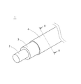
- FIG. 1 is a perspective view showing an appearance of an insulated electric wire with a fusion bonding layer according to the present disclosure.
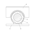
- FIG. 2 is a sectional view taken along line AA of FIG.
- FIG. 3 is a cross-sectional view in which the insulated wire with the fusion bonding layer according to the present disclosure is fused to an adherend.
- FIG. 4 is a cross-sectional view in which two insulated electric wires with a fusion layer according to the present disclosure are bundled and fused.
- FIG. 5: is a figure which shows the evaluation method of adhesive strength of the electric wire with a fusion bonding layer.
- [5A] is a diagram showing a method of fusing an electric wire with a fusion layer to an adherend
- [5B] is a diagram showing a method of peeling off the electric wire with a fusion layer.
- the insulated electric wire with the fusion layer of the present disclosure has a conductor, an insulation coating layer that covers the outer periphery of the conductor, and a fusion layer that is provided outside the insulation coating layer and that is fused by heat.
- the insulation coating layer contains polyvinyl chloride
- the fusion bonding layer contains a modified polyolefin resin and a polyamide resin.
- the insulated wire with a fusion bonding layer of the present disclosure by including a modified polyolefin resin and a heat-fusible fusion bonding layer containing a polyamide resin, it contributes to space saving at the time of a policy, and Excellent adhesion strength between the insulation coating layer containing vinyl chloride and the fusion layer.
- the electric wire with the fusion layer has excellent adhesive strength between the insulating coating layer and the fusion layer, so that a part of the fusion layer is not stretched and the load is dispersed over the entire electric wire. , It is difficult for the wires to come off.
- the polyamide resin is preferably a nylon hot melt resin. This is because the polyamide resin has high crystallinity and excellent chemical resistance. Further, since the nylon hot melt resin is composed of a monomer having a shorter carbon chain than other polyamide hot melt resins, the density of amide bonds in the polyamide resin is high, and the nylon coating and the fusion bonding layer This is because it has excellent adhesive strength.
- the fusion layer preferably contains 5 parts by mass or more of a polyamide resin with respect to 100 parts by mass of the polymer component. This is because the adhesive strength between the insulating coating layer and the fusion bonding layer is particularly excellent.
- the fusion bonding layer is provided on the outer side of the insulating coating layer over the entire circumference in the circumferential direction. This is because the adhesion area between the fusion layer and the insulating coating layer increases. Further, even if the fusing layer has a ring-shaped cross section and the fusing layer and the insulating coating are separated, the electric wire does not fall off immediately and the electric wire can be held.
- the insulated electric wire with the fusion layer is preferably fused to the member containing the polyolefin resin via the fusion layer. This is because the adhesive strength is excellent when a member containing a polyolefin resin is used as the adherend.
- An insulated electric wire 1 with a fusion bonding layer has an insulated electric wire that includes a conductor 2 and an insulating coating layer 3 that covers the outer periphery of the conductor 2, and further includes a modified polyolefin resin and a polyamide resin outside thereof.
- the fusion layer 4 is provided.
- the fusion bonding layer 4 softens and fuses at a temperature lower than the heat resistant temperature of the insulating coating layer 3.
- the modified polyolefin resin constituting the fusion bonding layer 4 is obtained by copolymerizing or graft-polymerizing a polymerizable monomer having a functional group such as a carboxy group, an ester group or an acid anhydride group, with a base polyolefin having an ⁇ -olefin as a monomer.
- This is a polyolefin having functional groups introduced therein. By introducing these functional groups, the adhesive strength to the adherend 5 during fusion bonding is excellent.
- the modified polyolefin resin has an acid anhydride group, the adhesive strength is particularly excellent.
- the modified polyolefin resin may be used alone or in combination of two or more.
- the modified polyolefin resin preferably has a melting point of 185° C. or lower, more preferably 160° C. or lower.
- the melting point is 185° C. or lower, an increase in the softening point of the fusion bonding layer 4 can be suppressed, and the conductor 2 and the insulating coating layer 3 are less likely to deteriorate due to heating during fusion bonding.
- the lower limit of the melting point is not particularly limited, but it is preferably 80° C. or higher. When the melting point is 80° C. or higher, the fusion layer 4 is likely to be stable at the operating temperature of the insulated wire 1 with the fusion layer.
- the melting point of the modified polyolefin resin is represented by the peak top temperature of the endothermic peak in "Differential scanning calorimetry (DSC)".
- the modified polyolefin resin forming the fusion layer 4 preferably has a melt viscosity at 160° C. of about 40 to 4000 Pa ⁇ s.
- the melt viscosity of the modified polyolefin resin is 40 Pa ⁇ s or more, the shape of the fusion layer 4 is likely to be stable and has excellent extrusion moldability, and the shape of the fusion layer 4 is less likely to collapse due to heating during fusion. ..
- the modified polyolefin resin has a melt viscosity of 4000 Pa ⁇ s or less, it is easy to secure a fusion-bonded surface to the adherend 5 during fusion-bonding.
- the melt viscosity of the modified polyolefin resin is measured with a capillary rheometer.
- the polyamide resin forming the fusion bonding layer 4 is not particularly limited as long as it is a polymer bonded by an amide bond.
- a nylon-based or dimer acid-based resin can be used.
- the polyamide resin is preferably a nylon-based hot melt resin.
- the nylon-based hot melt resin is a random copolymerized polyamide resin containing a saturated aliphatic monomer as a main constituent unit.
- the nylon-based hot melt resin preferably has a structure of any one of lactam, amino acid, dicarboxylic acid and diamine, and preferably has a saturated aliphatic compound having about 6 to 12 carbon atoms as a monomer.
- Such a monomer may be used as a main constituent unit, and a monomer having more than 12 carbon atoms or an alicyclic or aromatic compound may be added as a monomer.
- Properties such as crystallinity and softening point of the nylon-based hot-melt resin can be appropriately adjusted by combining a plurality of monomers having different carbon numbers and an alicyclic or aromatic monomer.
- a hot melt resin having a polyamide structure a hot melt resin mainly composed of dimer acid obtained by dimerizing (or trimerizing) unsaturated fatty acid and diamine is often used.
- the dimer acid is mainly made of linoleic acid, oleic acid and the like, has a carbon number of about 36, and has a dicarboxylic acid structure having a branched chain and an unsaturated bond in the molecule.
- a polyamide resin having dimer acid as a monomer has a complicated structure having many branch points and cross-linking points in its molecular structure, and its melting point tends to be lowered due to a decrease in crystallinity.
- a nylon-based hot-melt resin containing a saturated aliphatic monomer as a main constituent unit has a basic skeleton having a linear structure and has a high crystallinity. Thereby, it has excellent chemical resistance.
- a monomer having a relatively short carbon chain as compared with dimer acid, the density of amide bonds is increased and the adhesive strength to the insulating coating layer and the adherend is excellent.
- the nylon hot melt resin is colorless and transparent or light yellow, it can be easily colored and is excellent in distinguishability and appearance when the fusion bonding layer 4 is provided on the outer circumference of the electric wire.
- the polyamide resin preferably has a melting point of 80 to 160°C. More preferably, it is 85 to 150°C.
- the melting point is 160° C. or lower, an increase in the softening point of the fusion bonding layer 4 can be suppressed, and the conductor 2 and the insulating coating layer 3 are less likely to deteriorate due to heating during fusion bonding.
- the melting point is 80° C. or higher, the fusion layer 4 is likely to be stable at the operating temperature of the insulated wire 1 with the fusion layer.
- the melting point of the polyamide resin is represented by the peak top temperature of the endothermic peak in "Differential scanning calorimetry (DSC)".
- the polyamide resin forming the fusion bonding layer 4 preferably has, for example, a melt viscosity at 160° C. of about 40 to 4000 Pa ⁇ s.
- a melt viscosity at 160° C. of about 40 to 4000 Pa ⁇ s.
- the melt viscosity of the polyamide resin is 40 Pa ⁇ s or more, the shape of the fusion layer 4 is likely to be stable, the extrusion moldability is excellent, and the shape of the fusion layer 4 is less likely to collapse due to heating during fusion.
- the melt viscosity of the polyamide resin is 4000 Pa ⁇ s or less, it is easy to secure a fusion-bonding surface for the adherend 5 during fusion-bonding.
- the melt viscosity of the polyamide resin is measured with a capillary rheometer.
- the polyamide resin is preferably contained in an amount of 5 parts by mass or more based on 100 parts by mass of the polymer component constituting the fusion bonding layer 4.
- the amount is more preferably 10 parts by mass or more, and further preferably 20 parts by mass or more.
- the adhesive strength with the insulating coating layer 3 containing polyvinyl chloride is excellent.
- the upper limit of the content of the polyamide resin is not particularly limited, for example, when the adherend 5 contains a polyolefin resin, if the content of the polyamide resin in the fusion bonding layer 4 becomes too large, The adhesive strength may be reduced. From such a viewpoint, the content of the polyamide resin is preferably 70 parts by mass or less with respect to 100 parts by mass of the polymer component constituting the fusion bonding layer 4.
- the fusing layer 4 may be composed of one layer or may be formed by laminating a plurality of layers. When it is composed of a plurality of layers, for example, by arranging a layer containing a large amount of polyamide resin in an inner layer close to the insulating coating layer 3, the adhesive strength between the insulating coating layer 3 and the fusion bonding layer 4 is improved. At this time, it suffices that the entire fusion-bonding layer contains the modified polyolefin resin and the polyamide resin, and the total content of the entire fusion-bonding layer preferably has the above content ratio.
- the fusing layer 4 may contain components other than the modified polyolefin resin and the polyamide resin within a range that does not impair the object of the present disclosure.
- examples of other components include additives such as an inorganic filler, a plasticizer, a stabilizer, a pigment, and an antioxidant.
- the fusion bonding layer 4 may contain a polymer component other than the modified polyolefin resin and the polyamide resin.
- the total amount of the polymer components constituting the fusion layer 4 is 100 parts by mass. It is preferably 30 parts by mass or less.
- the inorganic filler as an additive, silica, diatomaceous earth, glass spheres, talc, clay, alumina, magnesium oxide, zinc oxide, antimony trioxide, metal oxides such as molybdenum oxide, metal hydroxide such as magnesium hydroxide.
- metal carbonates such as calcium carbonate and magnesium carbonate, metal boric acid such as zinc borate and barium metaborate, and hydrotalcites. These may be used alone or in combination of two or more.
- the softening point of the fusion bonding layer 4 is preferably at least lower than the softening point of the insulating coating layer 3. Specifically, it is preferably 80 to 160°C. When the softening point is 160° C. or lower, when the fusion bonding layer 4 is fused, deterioration of the conductor 2 and the insulation coating layer 3 and deformation of the insulation coating layer 3 due to heating are less likely to occur. On the other hand, when the softening point is 80° C. or higher, the fusion layer 4 is likely to be stable at the operating temperature of the insulated wire 1 with the fusion layer.
- the softening point of the fusing layer 4 and the softening point of the insulating coating layer 3 are represented by the peak top temperature of the endothermic peak in "Differential scanning calorimetry (DSC)".
- an ordinary insulated electric wire which is generally used in the past can be used.
- an insulated wire having the conductor 2 and the insulating coating layer 3 that covers the outer periphery of the conductor 2 may be used.
- Copper is generally used for the conductor 2, but metal materials such as aluminum and magnesium can be used in addition to copper. These metallic materials may be alloys. Other metal materials for forming an alloy include iron, nickel, magnesium, silicon, combinations thereof, and the like.
- the conductor 2 may be composed of a single wire, or may be composed of a twisted wire formed by twisting a plurality of element wires.
- Examples of the material forming the insulating coating layer 3 include polyvinyl chloride, rubber, and polyolefin. These may be used alone or in combination of two or more. Further, various additives may be appropriately added to these materials.
- the insulation coating is often composed of polyvinyl chloride.
- the adhesion strength between polyvinyl chloride and the modified polyolefin resin contained in the fusion layer 4 is weak, and in the conventional fusion layer, peeling is likely to occur at the interface between the fusion layer and the insulating coating layer.
- the fusion bonding layer 4 contains the modified polyolefin resin and the polyamide resin, even when the insulation coating layer 3 contains polyvinyl chloride, the fusion bonding layer 4 and the insulation coating layer are included. Excellent adhesion strength with 3.
- the insulating coating layer 3 and the fusion bonding layer 3 can be formed by, for example, extruding a material by heating and kneading the materials forming the respective layers. That is, the resin forming the insulating coating layer 3 and various additive components that are added as necessary are mixed, and the composition obtained by heating and kneading is extruded around the conductor 2 by an extruder to form the insulating coating layer 3. , Make an insulated wire. After that, the modified polyolefin resin and the polyamide resin, and various additive components that are added as necessary, are mixed, and the composition that is heated and kneaded is extruded to the outside of the insulated wire by an extruder to form the fusion layer 4. Thereby, the insulated electric wire 1 with a fusion bonding layer can be produced.
- the fusing layer 4 may be formed on the outer side of the insulating coating layer 3 so as to have a ring-shaped cross section over the entire circumference in the circumferential direction, or on the outer side of the insulating coating layer 3. It may be formed only partially in the direction.
- the fusion bonding layer 4 is formed over the entire outer circumference of the insulating coating layer 3, the bonding area between the fusion bonding layer 4 and the insulating coating layer 3 is large, and the adhesive strength is excellent.
- the fusing layer 4 is formed in a ring shape, even if the fusing layer 4 and the insulating coating layer 3 are separated, the electric wire does not immediately fall off, and the tensile strength of the fusing layer 4 is reduced. It can hold an electric wire within the range. Further, the fusion bonding layer 4 need not be formed over the entire area in the length direction of the insulated wire.
- the thickness of the conductor 2 and the thickness of the insulating coating layer 3 may be within the range of normally used insulated wires.
- the fusion layer 4 preferably has a thickness of 0.03 to 0.12 mm. When it is 0.03 mm or more, it is easy to secure a sufficient fused surface, and when it is 0.12 mm or less, it is possible to prevent the thickness of the entire insulated electric wire with a fused layer 1 from excessively increasing.
- the fusion layer 4 By heating the insulated electric wire 1 with the fusion layer, the fusion layer 4 is softened and can be fused.
- the heating method is not particularly limited, but in addition to directly heating the insulated wire 1 with the fusion bonding layer or the adherend 5, an ultrasonic generator such as a horn H is used as shown in FIG. Examples thereof include a method of generating frictional heat between the fusion layer 4 and the adherend 5.
- the fused portion can be locally heated without excessively raising the temperature of the insulated wire 1 with the fused layer. Deterioration can be suppressed.
- the insulating coating layer 3 and the fusion bonding layer 4 are separately provided, and heating is performed at a temperature equal to or higher than the softening point of the fusion bonding layer 4 and lower than the softening point of the insulating coating layer 3, so that the insulation during the fusion The deformation of the coating layer 3 can be suppressed, and the insulated electric wire 1 with the fusion bonding layer can be fused without impairing the performance as an insulated electric wire.
- the adherend 5 to which the insulated wire 1 with the fusion layer is fused is not particularly limited, but examples thereof include resin members such as polyolefin and polyester, and metal members such as iron, aluminum and stainless steel. Can be mentioned. Although many members made of polyolefin resin are used in vehicles such as automobiles, the insulated electric wire 1 with a fusion bonding layer according to the present disclosure contains a modified polyolefin resin in the fusion bonding layer 4, and therefore is made of a polyolefin resin. Particularly excellent in adhesive strength to members.
- the insulated electric wire with the fusion layer 1 has a plurality of insulated electric wires 1 with the fusion layer as shown in FIG. 4 in addition to the purpose of fixing the electric wire to the body of the automobile or the housing of the device. It is also effective when they are fused together and used in a bundle.
- Examples 1-5) Preparation of composition for fusing layer
- acid-modified polyolefin manufactured by Toyobo Co., Ltd., “Toyo Tac M-312”
- nylon hot melt resin manufactured by Arkema, “Platamid M1276”
- the mixture was kneaded using a machine to prepare a composition for a fusion bonding layer.
- the prepared fusion layer composition was extruded around the outer circumference of the insulated wire at 200° C. to form a fusion layer having a thickness of 0.1 mm.
- Samples 1 to 5 are the same as Samples 1 to 5 except that the fused layer was formed using only modified polypropylene without using a polyamide resin.
- the insulated wire 11 with the fusion bonding layer is placed on the polypropylene plate 16 so that 2 cm from the end is in contact, and the other portion is protected by the release sheet 17, and then the horn is placed from above.
- the ultrasonic wave of 28 kHz with H for about 1 second and applying a heat quantity of 50 J to fuse the fused wire with a fused layer 11 and the polypropylene plate 16, as shown in FIG. 5[5B]
- the part protected by the release sheet was folded back 180 degrees in the direction of the fused end and pulled in the axial direction to peel off the insulated wire 11 with the fusion layer.
- the peeling by the interface is 10% or less with respect to the length of the fusion-bonded portion in the axial direction, and the peeling by the interface is 30% or less. ⁇ , peeling by the interface of 50% or less was “ ⁇ ”, and peeling by the interface of more than 50% was rejected “x”.
- the sample 11 containing no polyamide resin in the fusion layer has poor adhesion strength with the insulating coating layer.
- Samples 1 to 5 containing the polyamide resin in the fusion layer showed excellent adhesive strength to the insulating coating layer.
- the adhesive strength to the polypropylene plate the smaller the blending amount of the polyamide resin, the more excellent the adhesive strength tended to be.
- Samples 1 and 2 showed high adhesive strength to the insulating coating layer, but the adhesive strength to the polypropylene plate was high. But tends to be slightly inferior.
- excellent adhesive strength was exhibited with respect to both the insulating coating layer and the polypropylene plate, and many cohesive failures were observed in which the fusion bonding layer itself was broken.
Landscapes
- Engineering & Computer Science (AREA)
- Manufacturing & Machinery (AREA)
- Insulated Conductors (AREA)
- Adhesives Or Adhesive Processes (AREA)
- Organic Insulating Materials (AREA)
Abstract
絶縁被覆層とその外側に設けられた融着層との接着強度に優れる融着層付き絶縁電線を提供する。 導体2と、導体2の外周を被覆する絶縁被覆層3と、絶縁被覆層3の外側に設けられ、熱により融着する融着層4とを有し、絶縁被覆層3は、ポリ塩化ビニルを含有し、融着層4は、変性ポリオレフィン樹脂と、ポリアミド樹脂とを含有する、融着層付き絶縁電線1とする。
Description
本開示は、融着層付き絶縁電線に関し、さらに詳しくは、導体を被覆する絶縁被覆の外側に熱融着性の融着層を有する融着層付き絶縁電線に関するものである。
自動車等の車両や電気・電子機器には、導体と導体の外周を被覆する絶縁被覆とを有する絶縁電線が数多く使用されている。近年では、自動車等や電気・電子機器の高性能化に伴い、使用される絶縁電線の数が増加している。従来、このような絶縁電線は、クランプのような固定金具等を用いて、自動車のボディや機器の筐体等に固定して使用されてきた。しかしながら、使用される絶縁電線が増えることにより、固定金具等が占めるスペースが大きくなり、その省スペース化が求められている。
上記課題に対し、例えば、特許文献1に開示されるような、変性ポリオレフィン樹脂より成る融着層を外周に有する絶縁電線を用いると、固定金具等を用いることなく、融着層を介して絶縁電線をボディや筐体等に直接固定することができ、省スペース化に有効である。
従来、導体の外周を被覆する絶縁被覆の材料としては、ポリ塩化ビニル組成物が多く用いられている。融着層は、絶縁電線の絶縁被覆層の外側に、絶縁被覆層と接触するように設けられているが、絶縁被覆に用いられることの多いポリ塩化ビニルと、特許文献1の融着層を構成する変性ポリオレフィン樹脂とは、互いに接着強度が弱く、絶縁被覆層と融着層との界面において剥離が発生しやすい問題があった。電線に負荷がかかった際に、絶縁被覆層と融着層との界面が剥離すると、外側の融着層に負荷が集中し、結果として電線全体の接着強度が低下してしまう。
本開示は上記問題に鑑み、絶縁被覆層とその外側に設けられた融着層との接着強度に優れる融着層付き絶縁電線を提供することを課題とする。
本開示の融着層付き絶縁電線は、導体と、前記導体の外周を被覆する絶縁被覆層と、前記絶縁被覆層の外側に設けられ、熱により融着する融着層とを有し、前記絶縁被覆層は、ポリ塩化ビニルを含有し、前記融着層は、変性ポリオレフィン樹脂と、ポリアミド樹脂とを含有することを要旨とするものである。
本開示の融着層付き絶縁電線によれば、絶縁被覆層とその外側に設けられた融着層との接着強度に優れる。
[本開示の実施形態の説明]
最初に本開示の実施態様を列記して説明する。
最初に本開示の実施態様を列記して説明する。
(1)本開示の融着層付き絶縁電線は、導体と、前記導体の外周を被覆する絶縁被覆層と、前記絶縁被覆層の外側に設けられ、熱により融着する融着層とを有し、前記絶縁被覆層は、ポリ塩化ビニルを含有し、前記融着層は、変性ポリオレフィン樹脂と、ポリアミド樹脂とを含有するものである。
本開示の融着層付き絶縁電線によれば、変性ポリオレフィン樹脂と、ポリアミド樹脂とを含有する熱融着性の融着層を有することにより、配策時の省スペース化に寄与するとともに、ポリ塩化ビニルを含有する絶縁被覆層と融着層との接着強度に優れる。
絶縁被覆層と融着層との接着強度が不十分であると、電線に負荷がかかった際に、絶縁被覆層と融着層との界面において剥離が発生し、被着体に直接接着している融着層に負荷が集中する。さらに、融着層が引き伸ばされ、薄くなった箇所から破断し、電線が被着体から脱落する。本開示に係る融着層付き電線は、絶縁被覆層と融着層との接着強度に優れることから、融着層の一部が引き伸ばされるようなことがなく、電線全体に負荷が分散するため、電線が脱落しにくくなる。
(2)前記ポリアミド樹脂は、ナイロン系ホットメルト樹脂であることが好ましい。ポリアミド樹脂の結晶化度が高く、耐薬品性に優れるからである。また、ナイロン系ホットメルト樹脂は、他のポリアミド系ホットメルト樹脂に比べ、炭素鎖の短いモノマーよりなることから、ポリアミド樹脂中のアミド結合の密度が高くなり、絶縁被覆層と融着層との接着強度に優れるからである。
(3)前記融着層は、ポリマー成分100質量部に対し、ポリアミド樹脂を5質量部以上含有することが好ましい。絶縁被覆層と融着層との接着強度に特に優れるからである。
(4)前記融着層は、前記絶縁被覆層の外側に、周方向の全周にわたって設けられていることが好ましい。融着層と絶縁被覆層との接着面積が大きくなるからである。また、融着層が断面輪状になり、仮に融着層と絶縁被覆とが剥離した場合においても、電線が直ちに脱落することはなく、電線を保持することができるからである。
(5)融着層付き絶縁電線は、前記融着層を介して、ポリオレフィン樹脂を含む部材に対して融着することが好ましい。被着体としてポリオレフィン樹脂を含む部材を用いた場合に、接着強度に優れるからである。
[本開示の実施形態の詳細]
本開示の融着層付き絶縁電線の具体例を、以下に図面を参照しつつ説明する。なお、本開示はこれらの例示に限定されるものではない。
本開示の融着層付き絶縁電線の具体例を、以下に図面を参照しつつ説明する。なお、本開示はこれらの例示に限定されるものではない。
本開示に係る融着層付き絶縁電線1は、導体2と、導体2の外周を被覆する絶縁被覆層3を有する絶縁電線を有し、さらにその外側に、変性ポリオレフィン樹脂とポリアミド樹脂とを含有する融着層4を有する。融着層4は、絶縁被覆層3の耐熱温度よりも低い温度において、軟化、融着する。
融着層4を構成する変性ポリオレフィン樹脂は、α-オレフィンをモノマーとするベースポリオレフィンに対し、カルボキシ基、エステル基、酸無水物基等の官能基を有する重合性モノマーを共重合またはグラフト重合することにより官能基を導入したポリオレフィンである。これらの官能基を導入することにより、融着時に被着体5に対する接着強度に優れる。変性ポリオレフィン樹脂が、酸無水物基を有すると接着強度に特に優れる。変性ポリオレフィン樹脂は、1種単独で用いてもよいし、2種以上を併用してもよい。
変性ポリオレフィン樹脂は、融点が185℃以下のものが好ましく、160℃以下のものがより好ましい。融点が185℃以下であると、融着層4の軟化点の上昇を抑制でき、融着させる際の加熱による導体2や絶縁被覆層3の劣化が起こりにくい。一方、融点の下限としては、特に限定しないが、80℃以上であることが好ましい。融点が80℃以上であると、融着層付き絶縁電線1の使用温度において、融着層4が安定しやすい。変性ポリオレフィン樹脂の融点は、「示差走査熱量測定(Differential scanning calorimetry:DSC)」における、吸熱ピークのピークトップ温度で表す。
融着層4を構成する変性ポリオレフィン樹脂は、例えば、160℃における溶融粘度が40~4000Pa・s程度であることが好ましい。変性ポリオレフィン樹脂の溶融粘度が、40Pa・s以上であると、融着層4の形状が安定しやすく、押出成形性に優れ、また、融着時の加熱により融着層4の形状が崩れにくい。一方、変性ポリオレフィン樹脂の溶融粘度が、4000Pa・s以下であると、融着時に被着体5に対して融着面を確保しやすい。変性ポリオレフィン樹脂の溶融粘度は、キャピラリーレオメーター(Capillary Rheometer)により測定する。
融着層4を構成するポリアミド樹脂は、アミド結合によって結合されたポリマーであれば、特に限定されない。例えば、ナイロン系、ダイマー酸系などの樹脂を用いることができる。ポリアミド樹脂としては、ナイロン系のホットメルト樹脂であることが好ましい。ナイロン系ホットメルト樹脂とは、飽和脂肪族モノマーを主な構成単位とするランダム共重合ポリアミド樹脂である。ナイロン系ホットメルト樹脂は、ラクタム、アミノ酸、ジカルボン酸、ジアミンのいずれかの構造を有し、炭素数6~12程度の飽和脂肪族化合物をモノマーとして有することが好ましい。このようなモノマーを主な構成単位とし、他に炭素数が12を超えるものや、脂環式または芳香族の化合物をモノマーとして加えてもよい。ナイロン系ホットメルト樹脂は、炭素数の異なる複数のモノマーや、脂環式または芳香族のモノマーを組み合わせることにより、結晶化度や軟化点等の特性を適宜調整することができる。
一般に、ポリアミド構造を有するホットメルト樹脂としては、不飽和脂肪酸が二量化(または三量化)したダイマー酸とジアミンを主な構成単位とするホットメルト樹脂が用いられることが多い。ダイマー酸は、主にリノール酸、オレイン酸等を原料とし、炭素数36程度で、分子内に分岐鎖と不飽和結合を有するジカルボン酸構造を有する。ダイマー酸をモノマーとするポリアミド樹脂は、分子構造中に分岐点や架橋点を多く有する複雑な構造となり、結晶化度が低下することにより融点が低くなりやすい。一方、飽和脂肪族モノマーを主な構成単位とするナイロン系ホットメルト樹脂は、直鎖構造の基本骨格を有し、結晶化度が高くなる。これにより、耐薬品性に優れる。また、ダイマー酸に比べ、比較的炭素鎖の短いモノマーを用いることにより、アミド結合の密度が高くなり、絶縁被覆層や被着体への接着強度に優れる。また、ナイロン系ホットメルト樹脂は、無色透明または淡黄色を呈することから、容易に着色することができ、電線の外周に融着層4を設けた際に、識別性、外観に優れる。
ポリアミド樹脂は、融点が80~160℃のものが好ましい。より好ましくは85~150℃である。融点が160℃以下であると、融着層4の軟化点の上昇を抑制でき、融着させる際の加熱による導体2や絶縁被覆層3の劣化が起こりにくい。一方、融点が80℃以上であると、融着層付き絶縁電線1の使用温度において融着層4が安定しやすい。ポリアミド樹脂の融点は、「示差走査熱量測定(Differential scanning calorimetry:DSC)」における、吸熱ピークのピークトップ温度で表す。
融着層4を構成するポリアミド樹脂は、例えば、160℃における溶融粘度が40~4000Pa・s程度であることが好ましい。ポリアミド樹脂の溶融粘度が、40Pa・s以上であると、融着層4の形状が安定しやすく、押出成形性に優れ、また、融着時の加熱により融着層4の形状が崩れにくい。一方、ポリアミド樹脂の溶融粘度が、4000Pa・s以下であると、融着時に被着体5に対して融着面を確保しやすい。ポリアミド樹脂の溶融粘度は、キャピラリーレオメーター(Capillary Rheometer)により測定する。
ポリアミド樹脂は、融着層4を構成するポリマー成分100質量部に対して5質量部以上含有することが好ましい。より好ましくは10質量部以上、さらに好ましくは20質量部以上である。ポリアミド樹脂を5質量部以上含有すると、ポリ塩化ビニルを含有する絶縁被覆層3との接着強度に優れる。一方、ポリアミド樹脂の含有量の上限は特に限定しないが、例えば、被着体5がポリオレフィン樹脂を含む場合、融着層4のポリアミド樹脂の含有量が多くなりすぎると、被着体5との接着強度が低下する虞がある。このような観点から、ポリアミド樹脂の含有量は、融着層4を構成するポリマー成分100質量部に対して70質量部以下とすることが好ましい。
融着層4は、一層よりなってもよいし、複数の層を積層していてもよい。複数の層からなる場合、例えば、絶縁被覆層3に近い内側の層に、ポリアミド樹脂を多く含む層を配置することで、絶縁被覆層3と融着層4との接着強度が向上する。このとき、融着層全体として変性ポリオレフィン樹脂とポリアミド樹脂を含有していればよく、融着層全体の総和において、上記のような含有割合であることが好ましい。
融着層4は、本開示の目的を損なわない範囲内で、変性ポリオレフィン樹脂、ポリアミド樹脂以外の他の成分を含有していても良い。他の成分としては、例えば、無機フィラー、可塑剤、安定剤、顔料、酸化防止剤などの添加剤を挙げることができる。また、融着層4は、変性ポリオレフィン樹脂、ポリアミド樹脂以外の他のポリマー成分を含有していても良い。他のポリマー成分を含有する場合には、絶縁被覆層3や被着体5に対する融着層4の接着強度を確保する観点から、融着層4を構成するポリマー成分の合計100質量部に対して30質量部以下であることが好ましい。
例えば、添加剤である無機フィラーとしては、シリカ、珪藻土、ガラス球、タルク、クレー、アルミナ、酸化マグネシウム、酸化亜鉛、三酸化アンチモン、酸化モリブデン等の金属酸化物、水酸化マグネシウム等の金属水酸化物、炭酸カルシウム、炭酸マグネシウム等の金属炭酸塩、硼酸亜鉛、メタ硼酸バリウムなどの金属ホウ酸、ハイドロタルサイト類などが挙げられる。これらは1種単独で用いてもよいし、2種以上を併用してもよい。
融着層4の軟化点は、少なくとも絶縁被覆層3の軟化点よりも低温であることが好ましい。具体的には、80~160℃であることが好ましい。軟化点が160℃以下であると、融着層4を融着させる際に、加熱による導体2や絶縁被覆層3の劣化や絶縁被覆層3の変形が起こりにくい。一方、軟化点が80℃以上であると、融着層付き絶縁電線1の使用温度において融着層4が安定しやすい。融着層4の軟化点および絶縁被覆層3の軟化点は、「示差走査熱量測定(Differential scanning calorimetry:DSC)」における、吸熱ピークのピークトップ温度で表す。
融着層4の内側に位置する絶縁電線は、従来一般に用いられる通常の絶縁電線を用いることができる。具体的には、導体2と、導体2の外周を被覆する絶縁被覆層3を有する絶縁電線であればよい。
導体2は、銅を用いることが一般的であるが、銅以外にも、アルミニウム、マグネシウムなどの金属材料を用いることもできる。これらの金属材料は、合金であってもよい。合金とするための他の金属材料としては、鉄、ニッケル、マグネシウム、シリコン、これらの組み合わせなどが挙げられる。導体2は、単線から構成されていてもよいし、複数本の素線を撚り合わせてなる撚線から構成されていてもよい。
絶縁被覆層3を構成する材料としては、例えば、ポリ塩化ビニル、ゴム、ポリオレフィンなどを例示することができる。これらは、1種を単独で用いてもよいし、2種以上を混合して用いてもよい。また、これらの材料中には、適宜、各種添加剤が添加されてもよい。
一般に、絶縁被覆は、ポリ塩化ビニルを含んで構成される場合が多い。しかしながら、ポリ塩化ビニルと融着層4に含まれる変性ポリオレフィン樹脂とは、接着強度が弱く、従来の融着層では、融着層と絶縁被覆層との界面において剥離が発生しやすかった。本開示においては、融着層4が、変性ポリオレフィン樹脂とポリアミド樹脂とを含有することにより、絶縁被覆層3がポリ塩化ビニルを含んでいる場合であっても、融着層4と絶縁被覆層3との接着強度に優れる。
絶縁被覆層3および融着層3は、例えば、それぞれの層を構成する材料を加熱混練し、押出成形機により形成することができる。すなわち、絶縁被覆層3を構成する樹脂と必要に応じて添加される各種添加成分を配合し、加熱混練した組成物を押出成形機により、導体2の周囲に押出し、絶縁被覆層3を形成し、絶縁電線を作製する。その後、変性ポリオレフィン樹脂とポリアミド樹脂、および必要に応じて添加される各種添加成分を配合し、加熱混練した組成物を押出成形機により、絶縁電線の外側に押出し、融着層4を形成することにより、融着層付き絶縁電線1を作製することができる。
融着層4は、図1、2に示すように、絶縁被覆層3の外側に周方向の全周にわたって、断面輪状となるように形成されてもよいし、絶縁被覆層3の外側の周方向に対して一部にのみ形成されてもよい。融着層4が、絶縁被覆層3の外側の全周にわたって形成されていると、融着層4と絶縁被覆層3との接着面積が大きくなり、接着強度に優れる。また、融着層4が輪状に形成されることにより、仮に融着層4と絶縁被覆層3とが剥離した場合においても、電線が直ちに脱落することはなく、融着層4の引張強度の範囲ではあるが電線を保持することができる。また、融着層4は、絶縁電線の長さ方向に対して、全域にわたって形成される必要はない。
導体2の太さおよび絶縁被覆層3の厚さは、通常用いられる絶縁電線の範囲でかまわない。一方、融着層4の厚さは、0.03~0.12mmであることが好ましい。0.03mm以上であると、十分な融着面を確保しやすく、また、0.12mm以下であると、融着層付き絶縁電線1全体の太さが、過度に増大することを防げる。
融着層付き絶縁電線1は、加熱することにより、融着層4が軟化し、融着することができる。加熱の方法は、特に限定されるものではないが、融着層付き絶縁電線1または被着体5を直接加熱する他、図3に示すように、ホーンHなどの超音波発生器を用い、融着層4と被着体5との間に摩擦熱を発生させる方法などが挙げられる。超音波発生器により加熱すると、融着層付き絶縁電線1の全体を過度に昇温することなく、融着箇所を局所的に加熱することができるため、導体2や絶縁被覆層3の熱による劣化を抑制することができる。
このとき、絶縁被覆層3と融着層4とを別に設け、融着層4の軟化点以上であり、かつ、絶縁被覆層3の軟化点以下の温度で加熱することにより、融着時に絶縁被覆層3の変形を抑制でき、絶縁電線としての性能を損なうことなく融着層付き絶縁電線1を融着することができる。
融着層付き絶縁電線1を融着させる被着体5は、特に限定されるものではないが、例えば、ポリオレフィン、ポリエステル等の樹脂製部材や、鉄、アルミニウム、ステンレス等の金属製部材等が挙げられる。自動車等の車両には、ポリオレフィン樹脂製の部材が多く用いられているが、本開示に係る融着層付き絶縁電線1は、融着層4に変性ポリオレフィン樹脂を含有することから、ポリオレフィン樹脂製部材への接着強度に特に優れる。
また、本開示に係る融着層付き絶縁電線1は、自動車のボディや機器の筐体等に電線を固定する目的のほか、図4に示すように、複数の融着層付き絶縁電線1を互いに融着させ、束ねて使用する際にも有効である。
以上、本開示の実施の形態について詳細に説明したが、本開示は上記実施の形態に何ら限定されるものではなく、本開示の要旨を逸脱しない範囲で種々の改変が可能である。
以下、本開示を実施例により詳細に説明するが、本開示は実施例により限定されるものではない。
(試料1~5)
(融着層用組成物の調製)
表1に示す割合(質量部)で、酸変性ポリオレフィン(東洋紡株式会社製、「トーヨータック M-312」)およびナイロン系ホットメルト樹脂(アルケマ製、「Platamid M1276」)を配合し、二軸押出機を用いて混練し、融着層用組成物を調製した。
(融着層用組成物の調製)
表1に示す割合(質量部)で、酸変性ポリオレフィン(東洋紡株式会社製、「トーヨータック M-312」)およびナイロン系ホットメルト樹脂(アルケマ製、「Platamid M1276」)を配合し、二軸押出機を用いて混練し、融着層用組成物を調製した。
(絶縁電線の作製)
ポリ塩化ビニル(信越化学工業製、「TK-1300」)100質量部と、衝撃改質剤(三菱ケミカル製、「メタブレンC-223A」)2質量部と、安定剤(アデカ製、「アデカスタブ RUP-110」)5質量部と、炭酸カルシウム(丸尾カルシウム製、「スーパー#1700」)5質量部と、可塑剤(花王製、「トリメックスN―08」)32質量部とを二軸押出機を用いて混練した後、導体断面積0.13mm2の撚線導体の周囲に被覆厚0.2mmで押出成形することにより絶縁電線を作製した。
ポリ塩化ビニル(信越化学工業製、「TK-1300」)100質量部と、衝撃改質剤(三菱ケミカル製、「メタブレンC-223A」)2質量部と、安定剤(アデカ製、「アデカスタブ RUP-110」)5質量部と、炭酸カルシウム(丸尾カルシウム製、「スーパー#1700」)5質量部と、可塑剤(花王製、「トリメックスN―08」)32質量部とを二軸押出機を用いて混練した後、導体断面積0.13mm2の撚線導体の周囲に被覆厚0.2mmで押出成形することにより絶縁電線を作製した。
(融着層の形成)
調製した融着層用組成物を、絶縁電線の外側全周に、200℃で押出成形することにより、厚さ0.1mmの融着層を形成した。
調製した融着層用組成物を、絶縁電線の外側全周に、200℃で押出成形することにより、厚さ0.1mmの融着層を形成した。
(試料11)
ポリアミド樹脂を用いず、変性ポリプロピレンのみを用いて融着層を形成したこと以外は、試料1~5と同様である。
ポリアミド樹脂を用いず、変性ポリプロピレンのみを用いて融着層を形成したこと以外は、試料1~5と同様である。
(評価)
図5[5A]に示すように、ポリプロピレン板16上に、融着層付き絶縁電線11を端部から2cmが接するように置き、その他の部分を剥離シート17で保護した後、上方から、ホーンHにより、28kHzの超音波を約1秒照射し、50Jの熱量を与えて、融着層付き絶縁電線11とポリプロピレン板16とを融着させた後、図5[5B]に示すように、剥離シートで保護していた箇所を融着している端部の方向に180度折り返し、軸線方向に引っ張り、融着層付き絶縁電線11の引き剥がしを行った。
融着層と絶縁被覆層との界面について、融着箇所の軸線方向の長さに対して、界面による剥離が10%以下のものを「◎」、界面による剥離が30%以下のものを「○」、界面による剥離が50%以下ものを「△」、界面による剥離が50%を超えるものを不合格「×」とした。
図5[5A]に示すように、ポリプロピレン板16上に、融着層付き絶縁電線11を端部から2cmが接するように置き、その他の部分を剥離シート17で保護した後、上方から、ホーンHにより、28kHzの超音波を約1秒照射し、50Jの熱量を与えて、融着層付き絶縁電線11とポリプロピレン板16とを融着させた後、図5[5B]に示すように、剥離シートで保護していた箇所を融着している端部の方向に180度折り返し、軸線方向に引っ張り、融着層付き絶縁電線11の引き剥がしを行った。
融着層と絶縁被覆層との界面について、融着箇所の軸線方向の長さに対して、界面による剥離が10%以下のものを「◎」、界面による剥離が30%以下のものを「○」、界面による剥離が50%以下ものを「△」、界面による剥離が50%を超えるものを不合格「×」とした。

融着層にポリアミド樹脂を含まない試料11は、絶縁被覆層との接着強度に劣る。一方、融着層にポリアミド樹脂を含む試料1~5は、絶縁被覆層に対して、優れた接着強度を示した。ポリプロピレン板に対する接着強度については、ポリアミド樹脂の配合量が少ないほど優れる傾向がみられ、試料1、2は、絶縁被覆層に対して高い接着強度を示したが、ポリプロピレン板に対しては接着強度がやや劣る傾向がある。なお、試料3~5においては、絶縁被覆層およびポリプロピレン板の双方に対して優れた接着強度を示し、融着層自体が破断する凝集破壊が多く見られた。
1 融着層付き絶縁電線
2 導体
3 絶縁被覆層
4 融着層
5 被着体
11 融着層付き絶縁電線
16 ポリプロピレン板
17 剥離シート
H ホーン(超音波発生器)
2 導体
3 絶縁被覆層
4 融着層
5 被着体
11 融着層付き絶縁電線
16 ポリプロピレン板
17 剥離シート
H ホーン(超音波発生器)
Claims (5)
- 導体と、前記導体の外周を被覆する絶縁被覆層と、
前記絶縁被覆層の外側に設けられ、熱により融着する融着層とを有し、
前記絶縁被覆層は、ポリ塩化ビニルを含有し、
前記融着層は、変性ポリオレフィン樹脂と、ポリアミド樹脂とを含有する、融着層付き絶縁電線。 - 前記ポリアミド樹脂は、ナイロン系ホットメルト樹脂である、請求項1に記載の融着層付き絶縁電線。
- 前記融着層は、ポリマー成分100質量部に対し、ポリアミド樹脂を5質量部以上含有する、請求項1または請求項2に記載の融着層付き絶縁電線。
- 前記融着層は、前記絶縁被覆層の外側に、周方向の全周にわたって設けられている、請求項1から請求項3のいずれか1項に記載の融着層付き絶縁電線。
- 前記融着層を介して、ポリオレフィン樹脂を含む部材に対して融着する、請求項1から請求項4のいずれか1項に記載の融着層付き絶縁電線。
Priority Applications (3)
| Application Number | Priority Date | Filing Date | Title |
|---|---|---|---|
| US17/422,291 US12014849B2 (en) | 2019-01-16 | 2019-12-26 | Insulated wire with bonding layer of polyolefin and polyamide |
| DE112019006657.9T DE112019006657T5 (de) | 2019-01-16 | 2019-12-26 | Isolierter Draht mit Klebeschicht |
| CN201980088560.8A CN113316825B (zh) | 2019-01-16 | 2019-12-26 | 带熔接层的绝缘电线 |
Applications Claiming Priority (2)
| Application Number | Priority Date | Filing Date | Title |
|---|---|---|---|
| JP2019004841A JP7124723B2 (ja) | 2019-01-16 | 2019-01-16 | 融着層付き絶縁電線 |
| JP2019-004841 | 2019-01-16 |
Publications (1)
| Publication Number | Publication Date |
|---|---|
| WO2020149134A1 true WO2020149134A1 (ja) | 2020-07-23 |
Family
ID=71614337
Family Applications (1)
| Application Number | Title | Priority Date | Filing Date |
|---|---|---|---|
| PCT/JP2019/051051 Ceased WO2020149134A1 (ja) | 2019-01-16 | 2019-12-26 | 融着層付き絶縁電線 |
Country Status (5)
| Country | Link |
|---|---|
| US (1) | US12014849B2 (ja) |
| JP (1) | JP7124723B2 (ja) |
| CN (1) | CN113316825B (ja) |
| DE (1) | DE112019006657T5 (ja) |
| WO (1) | WO2020149134A1 (ja) |
Cited By (1)
| Publication number | Priority date | Publication date | Assignee | Title |
|---|---|---|---|---|
| EP4089146A1 (en) | 2021-05-12 | 2022-11-16 | Arkema France | Hot-melt adhesive composition |
Families Citing this family (1)
| Publication number | Priority date | Publication date | Assignee | Title |
|---|---|---|---|---|
| JP7124723B2 (ja) * | 2019-01-16 | 2022-08-24 | 株式会社オートネットワーク技術研究所 | 融着層付き絶縁電線 |
Citations (2)
| Publication number | Priority date | Publication date | Assignee | Title |
|---|---|---|---|---|
| JPH05120923A (ja) * | 1991-10-30 | 1993-05-18 | Kanegafuchi Chem Ind Co Ltd | 自己融着性巻線 |
| JP2001135152A (ja) * | 1999-11-01 | 2001-05-18 | Sumitomo Wiring Syst Ltd | 熱融着性電線、熱融着性テープおよび熱融着性シート |
Family Cites Families (52)
| Publication number | Priority date | Publication date | Assignee | Title |
|---|---|---|---|---|
| US3616191A (en) * | 1967-11-29 | 1971-10-26 | Morton Int Inc | Low temperature extrusion primer |
| GB1453621A (en) * | 1972-11-10 | 1976-10-27 | Toyo Seikan Kaisha Ltd | Sterilised food packages |
| JP2541292B2 (ja) * | 1988-08-23 | 1996-10-09 | 住友化学工業株式会社 | 耐衝撃性ポリアミド樹脂組成物の製造法 |
| JP2867406B2 (ja) * | 1989-02-09 | 1999-03-08 | 住友化学工業株式会社 | 多相構造体およびその製造方法 |
| EP0483954A1 (en) * | 1990-11-01 | 1992-05-06 | Huntsman Corporation | Modified polyamides |
| DE69419998T2 (de) * | 1993-10-12 | 1999-12-02 | Elf Atochem S.A., Puteaux | Gegenstand aus Polyamid/Polyolefin-Mischung mit Verbindungsnaht |
| JPH09235519A (ja) * | 1996-03-01 | 1997-09-09 | Daicel Chem Ind Ltd | ホットメルト型接着フィルムと加工品 |
| DK0981821T3 (da) * | 1997-05-15 | 2002-10-21 | Pirelli Cavi E Sistemi Spa | Kabel med stødresistent coating |
| JPH11236485A (ja) * | 1998-02-20 | 1999-08-31 | Daicel Chem Ind Ltd | 樹脂組成物及びそれを用いた熱転写シート |
| EP1114734A1 (en) * | 1999-06-04 | 2001-07-11 | DAICEL CHEMICAL INDUSTRIES, Ltd. | Resin composition for ink-jet recording sheet and recording sheet made with the same |
| JP2004148839A (ja) * | 2000-01-25 | 2004-05-27 | Hiraoka & Co Ltd | 接合性に優れた表面処理シート、並びにその接合方法及び貼着方法 |
| ES2311515T3 (es) * | 2000-02-21 | 2009-02-16 | Prysmian Cavi E Sistemi Energia S.R.L. | Cable autoextinguible resistente al impacto. |
| EP1221464B1 (en) * | 2001-01-09 | 2007-09-26 | Sumitomo Wiring Systems, Ltd. | Resin composition, method of making it and electrical wire covered with it |
| JP2002237219A (ja) | 2001-02-08 | 2002-08-23 | Yazaki Corp | 融着層付き電線及び融着層付き電線の製造方法 |
| US6740396B2 (en) * | 2001-02-26 | 2004-05-25 | Pirelli Cavi E Sistemi S.P.A. | Cable with coating of a composite material |
| ATE466367T1 (de) * | 2001-02-26 | 2010-05-15 | Prysmian Spa | Kabel mit einem überzug aus verbundwerkstoff |
| CN1326159C (zh) * | 2002-04-16 | 2007-07-11 | 皮雷利&C.有限公司 | 电缆及其制造过程 |
| JP4201573B2 (ja) * | 2002-10-29 | 2008-12-24 | 矢崎総業株式会社 | 電線被覆用樹脂組成物およびそれを用いた電線 |
| US7459635B2 (en) * | 2003-07-25 | 2008-12-02 | Prysmian Cavi E Sistemi Energia S.R.L. | Continuous process for manufacturing electrical cables |
| US7518064B2 (en) * | 2003-07-30 | 2009-04-14 | Sumitomo Electric Industries, Ltd. | Halogen free flame retardant cable |
| EP1756841B1 (en) * | 2004-04-27 | 2017-03-08 | Prysmian S.p.A. | Process for manufacturing a cable resistant to external chemical agents |
| US20060251802A1 (en) * | 2005-05-03 | 2006-11-09 | Kummer Randy D | Electrical cable having a surface with reduced coefficient of friction |
| CN100551987C (zh) * | 2005-07-01 | 2009-10-21 | 郎静明 | 人造雪及人造滑雪场 |
| KR20060115989A (ko) * | 2006-01-25 | 2006-11-13 | 피렐리 앤 씨. 에스.피.에이. | 전기 케이블의 연속적인 제조 방법 |
| US7714231B2 (en) * | 2007-02-13 | 2010-05-11 | Schlumberger Technology Corporation | Motor winding wire for a hydrocarbon application |
| JP2008270119A (ja) | 2007-04-25 | 2008-11-06 | Totoku Electric Co Ltd | 滑性・低発ガス性自己融着絶縁電線 |
| JP2009181850A (ja) * | 2008-01-31 | 2009-08-13 | Autonetworks Technologies Ltd | 絶縁電線 |
| EP2151830A1 (de) * | 2008-08-08 | 2010-02-10 | pp-mid GmbH | Polymerformkörper mit leitfähigen Strukturen auf der Oberfläche, sowie Verfahren zu dessen Herstellung |
| WO2010115173A1 (en) * | 2009-04-03 | 2010-10-07 | Vorbeck Materials Corp | Polymer compositions containing graphene sheets and graphite |
| US9424962B2 (en) * | 2009-12-23 | 2016-08-23 | Prysmian S.P.A. | Flexible electrical cable with resistance to external chemical agents |
| MX2012014615A (es) * | 2010-06-23 | 2013-02-07 | 3M Innovative Properties Co | Sistema de cableado con respaldo adhesivo para aplicaciones inalambricas en edificios. |
| JP5824792B2 (ja) * | 2010-08-23 | 2015-12-02 | 株式会社オートネットワーク技術研究所 | 防食用ポリアミド樹脂組成物および端子付き電線 |
| SA111320830B1 (ar) * | 2010-10-13 | 2014-10-16 | Baker Hughes Inc | جهاز هوائي وطريقة للعزل |
| HK1201633A1 (en) * | 2011-08-24 | 2015-09-04 | 宸鸿科技控股有限公司 | Patterned transparent conductors and related manufacturing methods |
| JP5888976B2 (ja) * | 2011-09-28 | 2016-03-22 | 富士フイルム株式会社 | 導電性組成物、導電性部材およびその製造方法、タッチパネル並びに太陽電池 |
| JP2015000905A (ja) * | 2013-06-14 | 2015-01-05 | 株式会社オートネットワーク技術研究所 | ポリオレフィン系樹脂組成物 |
| KR101800567B1 (ko) * | 2013-11-05 | 2017-11-22 | 미쓰이 가가쿠 가부시키가이샤 | 변성 프로필렌·α-올레핀 공중합체와 그의 제조 방법, 그것을 포함하는 코팅재, 성형용 수지 조성물 및 핫 멜트 조성물 |
| EP3187330B1 (en) * | 2014-08-29 | 2019-09-04 | Mitsubishi Gas Chemical Company, Inc. | Honeycomb structure and sandwich structure |
| JP6133249B2 (ja) * | 2014-09-09 | 2017-05-24 | 古河電気工業株式会社 | 絶縁電線、コイルおよび電気・電子機器ならびに絶縁電線の製造方法 |
| WO2016052394A1 (ja) * | 2014-09-30 | 2016-04-07 | 大日本印刷株式会社 | 電池用包装材料 |
| PL3235340T3 (pl) * | 2014-12-16 | 2020-11-30 | Saint-Gobain Glass France | Szyba z elektrycznym elementem przyłączeniowym i elastycznym kablem przyłączeniowym |
| CN106409407A (zh) * | 2015-03-18 | 2017-02-15 | 江苏亨通线缆科技有限公司 | 低衰减多芯电话线 |
| CN104804672A (zh) * | 2015-04-22 | 2015-07-29 | 深圳市沃尔核材股份有限公司 | 一种核电站电缆附件用热熔胶 |
| JP2017183168A (ja) * | 2016-03-31 | 2017-10-05 | 住友電装株式会社 | ワイヤーハーネス及びその製造方法 |
| JP6696861B2 (ja) * | 2016-08-24 | 2020-05-20 | 住友電気工業株式会社 | 車両用の被覆電線及び多芯ケーブル |
| KR101820399B1 (ko) * | 2017-06-09 | 2018-03-02 | 김은수 | 보온 및 단열용 샌드위치 판넬 |
| DE112018003122T5 (de) * | 2017-06-19 | 2020-03-05 | Autonetworks Technologies, Ltd. | Isolierter elektrischer Draht und Kabelbaum |
| JP6881358B2 (ja) * | 2018-03-09 | 2021-06-02 | 住友電装株式会社 | ワイヤハーネス |
| JP6838576B2 (ja) * | 2018-03-29 | 2021-03-03 | 株式会社オートネットワーク技術研究所 | ワイヤハーネス |
| JP6908184B2 (ja) * | 2018-04-25 | 2021-07-21 | ダイキン工業株式会社 | 撚り電線およびその製造方法 |
| JP7124723B2 (ja) * | 2019-01-16 | 2022-08-24 | 株式会社オートネットワーク技術研究所 | 融着層付き絶縁電線 |
| JP7419965B2 (ja) * | 2020-05-25 | 2024-01-23 | 株式会社オートネットワーク技術研究所 | 配線部材 |
-
2019
- 2019-01-16 JP JP2019004841A patent/JP7124723B2/ja active Active
- 2019-12-26 US US17/422,291 patent/US12014849B2/en active Active
- 2019-12-26 DE DE112019006657.9T patent/DE112019006657T5/de active Pending
- 2019-12-26 WO PCT/JP2019/051051 patent/WO2020149134A1/ja not_active Ceased
- 2019-12-26 CN CN201980088560.8A patent/CN113316825B/zh active Active
Patent Citations (2)
| Publication number | Priority date | Publication date | Assignee | Title |
|---|---|---|---|---|
| JPH05120923A (ja) * | 1991-10-30 | 1993-05-18 | Kanegafuchi Chem Ind Co Ltd | 自己融着性巻線 |
| JP2001135152A (ja) * | 1999-11-01 | 2001-05-18 | Sumitomo Wiring Syst Ltd | 熱融着性電線、熱融着性テープおよび熱融着性シート |
Cited By (2)
| Publication number | Priority date | Publication date | Assignee | Title |
|---|---|---|---|---|
| EP4089146A1 (en) | 2021-05-12 | 2022-11-16 | Arkema France | Hot-melt adhesive composition |
| WO2022238526A1 (en) | 2021-05-12 | 2022-11-17 | Arkema France | Hot-melt adhesive composition |
Also Published As
| Publication number | Publication date |
|---|---|
| CN113316825A (zh) | 2021-08-27 |
| JP7124723B2 (ja) | 2022-08-24 |
| DE112019006657T5 (de) | 2021-12-09 |
| US12014849B2 (en) | 2024-06-18 |
| US20220084721A1 (en) | 2022-03-17 |
| JP2020113491A (ja) | 2020-07-27 |
| CN113316825B (zh) | 2023-06-13 |
Similar Documents
| Publication | Publication Date | Title |
|---|---|---|
| CN103068925B (zh) | 防腐蚀用聚酰胺树脂组合物及具有端子的电线 | |
| CN102666928B (zh) | 防腐蚀剂、具有端子的包覆电线和线束 | |
| JP6630021B2 (ja) | 耐熱性2層熱収縮チューブ及び被覆対象物の被覆方法 | |
| WO2020149134A1 (ja) | 融着層付き絶縁電線 | |
| JP2019008988A (ja) | 端子付電線及びその製造方法 | |
| TW201017694A (en) | Multilayer insulated wire and transformer using same | |
| JP2012113963A (ja) | 端子付き電線 | |
| US10388428B2 (en) | Electric wire with connector, and wire harness | |
| TW201005762A (en) | Insulated wire | |
| JP7001048B2 (ja) | 融着層付き絶縁電線 | |
| JP6940029B2 (ja) | 電気絶縁ケーブル、センサ一体型ハーネス | |
| JP6796253B2 (ja) | 接着フィルム及びフラット配線材 | |
| JP2008258129A (ja) | 融着ヒータ線およびアルミ付ヒータ | |
| JP2009176475A (ja) | 絶縁電線 | |
| JP6638630B2 (ja) | 電線被覆材用組成物および絶縁電線 | |
| JPH05220908A (ja) | 多層チューブ | |
| JP2001237055A (ja) | ヒータ線 | |
| JP2026031746A (ja) | チューブ材 | |
| JP2013125738A (ja) | 端子付き電線 | |
| JP2010284895A (ja) | 積層体、チューブ、絶縁電線、及びこれらの製造方法 | |
| JP2017114954A (ja) | 接着剤組成物及び多層熱回復物品 | |
| KR20170130249A (ko) | 실리콘 피복으로 구성된 플랫 전기선 | |
| JPH10233120A (ja) | ケーブル | |
| WO2017098738A1 (ja) | 端子付電線 | |
| JPS63253809A (ja) | 電線接続部の絶縁被覆方法 |
Legal Events
| Date | Code | Title | Description |
|---|---|---|---|
| 121 | Ep: the epo has been informed by wipo that ep was designated in this application |
Ref document number: 19910632 Country of ref document: EP Kind code of ref document: A1 |
|
| 122 | Ep: pct application non-entry in european phase |
Ref document number: 19910632 Country of ref document: EP Kind code of ref document: A1 |