WO2020111027A1 - 電気化学素子用セパレータ - Google Patents
電気化学素子用セパレータ Download PDFInfo
- Publication number
- WO2020111027A1 WO2020111027A1 PCT/JP2019/046067 JP2019046067W WO2020111027A1 WO 2020111027 A1 WO2020111027 A1 WO 2020111027A1 JP 2019046067 W JP2019046067 W JP 2019046067W WO 2020111027 A1 WO2020111027 A1 WO 2020111027A1
- Authority
- WO
- WIPO (PCT)
- Prior art keywords
- particles
- separator
- hydroxide
- less
- hydrophilic
- Prior art date
- Legal status (The legal status is an assumption and is not a legal conclusion. Google has not performed a legal analysis and makes no representation as to the accuracy of the status listed.)
- Ceased
Links
Images

Classifications
-
- H—ELECTRICITY
- H01—ELECTRIC ELEMENTS
- H01M—PROCESSES OR MEANS, e.g. BATTERIES, FOR THE DIRECT CONVERSION OF CHEMICAL ENERGY INTO ELECTRICAL ENERGY
- H01M50/00—Constructional details or processes of manufacture of the non-active parts of electrochemical cells other than fuel cells, e.g. hybrid cells
- H01M50/40—Separators; Membranes; Diaphragms; Spacing elements inside cells
- H01M50/409—Separators, membranes or diaphragms characterised by the material
- H01M50/443—Particulate material
-
- H—ELECTRICITY
- H01—ELECTRIC ELEMENTS
- H01G—CAPACITORS; CAPACITORS, RECTIFIERS, DETECTORS, SWITCHING DEVICES, LIGHT-SENSITIVE OR TEMPERATURE-SENSITIVE DEVICES OF THE ELECTROLYTIC TYPE
- H01G11/00—Hybrid capacitors, i.e. capacitors having different positive and negative electrodes; Electric double-layer [EDL] capacitors; Processes for the manufacture thereof or of parts thereof
- H01G11/52—Separators
-
- Y—GENERAL TAGGING OF NEW TECHNOLOGICAL DEVELOPMENTS; GENERAL TAGGING OF CROSS-SECTIONAL TECHNOLOGIES SPANNING OVER SEVERAL SECTIONS OF THE IPC; TECHNICAL SUBJECTS COVERED BY FORMER USPC CROSS-REFERENCE ART COLLECTIONS [XRACs] AND DIGESTS
- Y02—TECHNOLOGIES OR APPLICATIONS FOR MITIGATION OR ADAPTATION AGAINST CLIMATE CHANGE
- Y02E—REDUCTION OF GREENHOUSE GAS [GHG] EMISSIONS, RELATED TO ENERGY GENERATION, TRANSMISSION OR DISTRIBUTION
- Y02E60/00—Enabling technologies; Technologies with a potential or indirect contribution to GHG emissions mitigation
- Y02E60/10—Energy storage using batteries
Definitions
- the present invention relates to a separator for electrochemical device. More specifically, it relates to a separator used for an electrochemical element such as a battery, a capacitor, a capacitor, a sensor and an electrolyzer.
- a zinc-alkaline secondary battery in which a porous layer of magnesium oxide that acts as a barrier layer that blocks acicular zinc crystals (dendrites) generated during charging is adhered (see, for example, Patent Document 1). ..
- the porous layer of magnesium oxide described in the above Patent Document 1 has room for further devising to prolong the life of the battery. Further, it is desired to extend the life of electrochemical devices other than batteries.
- the present invention has been made in view of the above circumstances, and an object thereof is to provide a method for extending the life of an electrochemical device.
- the present inventors have conducted various studies on methods for extending the life of an electrochemical device and focused on a separator used for the electrochemical device. Then, the inventors of the present invention can extend the life of an electrochemical device by including a hydrophobic particle and a hydrophilic particle each in a certain ratio or more, and by using a separator for an electrochemical device in which the content of a binder component is less than a certain ratio.
- the present invention has been made, and the present invention has been achieved by realizing that the above problems can be solved satisfactorily.
- the present invention is a separator used in an electrochemical device, wherein the separator contains hydrophobic particles, hydrophilic particles, and optionally a binding component, and hydrophobic particles/(hydrophilic particles and binding component Volume ratio of more than 20/80, the volume ratio of hydrophilic particles/(hydrophobic particles and binding component) exceeds 20/80, and of binding component/(hydrophobic particles and hydrophilic particles) The volume ratio is less than 30/70 for the electrochemical device separator.
- the present invention has the above-mentioned structure and can prolong the life of the electrochemical device.
- FIG. 4 is a triangular diagram showing the relationship between the cycle ratio and the volume ratio of hydrophobic particles, hydrophilic particles, and a binding component.
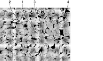
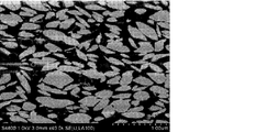
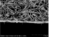
- 3 is a SEM photograph showing a cross section of the separator of Example 1 (40% by volume of hydrophobic particles, 50% by volume of hydrophilic particles, 10% by volume of a binding component).
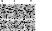
- 5 is an SEM photograph showing a cross section of a separator (hydrophobic particles 0% by volume, hydrophilic particles 80% by volume, binder component 20% by volume) of Comparative Example 1-1.
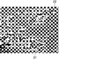
- 9 is a SEM photograph showing a cross section of a separator of Comparative Example 3.
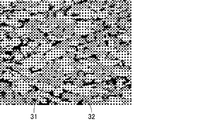
- 5 is a SEM photograph showing a cross section of the separator of Example 3.
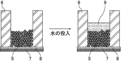
- 5 is a SEM photograph showing a cross section of the separator of Example 4-4 before immersion in the electrolytic solution. 5 is an SEM photograph showing a cross section of the separator of Example 4-4 after immersion in the electrolytic solution. It is a schematic diagram of a water permeability test.
- the electrochemical device separator of the present invention is a member that secures ionic conductivity between the positive electrode and the negative electrode while separating the positive electrode and the negative electrode, but as described above, the hydrophobic particles and the hydrophilic particles are respectively used. It is contained in a certain proportion or more and the content of the binding component is less than the certain proportion.
- the separator for an electrochemical device of the present invention has excellent durability due to its configuration, and particularly when used in an electrochemical device including an electrode that undergoes a morphological change with charge and discharge, a certain proportion of hydrophobic particles.
- the electrochemical device of the present invention due to the water repellency of the hydrophobic particles, the substantial amount of the electrolytic solution in the separator is limited, and the free active material derived from the separator is used. Since the ion (for example, zincate ion) concentration is low, it is possible to sufficiently suppress the growth of dendrites that occur during the process of the dissolution and precipitation reaction of the active material component (for example, zinc component), and the electrochemical device The life can be extended.
- the separator for electrochemical device of the present invention contains hydrophilic particles in a certain proportion or more, and the content of the binding component is less than the certain proportion, so that the hydrophilic particle surface serves as an ion conduction path and binds. It is possible to sufficiently prevent the gap between particles from being filled with the component when binding the particles, and it is possible to make the ionic conductivity of the separator sufficiently high. By making the ionic conductivity inside the electrochemical device sufficiently high and by using the electrochemical device having a low internal resistance, the electrochemical device can be appropriately driven, which contributes to a longer life.
- the hydrophobic particles can remarkably exhibit the above-mentioned water repellency in that they have a particle shape rather than a fibrous shape having a small specific surface area. Similarly, the hydrophilic particles have a particle shape, so that the ionic conductivity of the separator can be made very excellent.
- the volume ratio of the hydrophobic particles/(hydrophilic particles and binder component) is preferably 25/75 or more, and more preferably 37/63 or more.
- the volume ratio of the hydrophobic particles/(hydrophilic particles and binding component) is 80/20 because the volume ratio of the hydrophilic particles/(hydrophobic particles and binding component) exceeds 20/80. It is less than 70, preferably less than 70/30.
- the volume ratio of the hydrophilic particles/(hydrophobic particles and binding component) is preferably 30/70 or more.
- the volume ratio of the hydrophilic particles/(hydrophobic particles and binding component) is 80/20 because the volume ratio of the hydrophobic particles/(hydrophilic particles and binding component) exceeds 20/80.
- the volume ratio of the binder component/(hydrophobic particles and hydrophilic particles) is preferably 20/80 or less, more preferably 10/90 or less.
- the binder component is an arbitrary component, and the lower limit of the volume ratio of the binder component/(hydrophobic particles and hydrophilic particles) is preferably 0/100, more preferably 0.1/99. 9 and more preferably 1/99.
- hydrophobic particles the hydrophobic particles, the hydrophilic particles, the binding component which is an optional component, and the like contained in the separator for electrochemical device of the present invention will be described in order.
- the electrochemical device separator of the present invention contains hydrophobic particles.
- the hydrophobic particles mean particles having a water permeability of 0.01 g or less calculated by the following water permeability test.
- the hydrophobic particles are not particularly limited as long as the water permeation amount is 0.01 g or less, and for example, the entire particles may be particles composed of a hydrophobic material, or the surface thereof may be coated with a hydrophobic material. It may be a particle.
- the water permeability of the hydrophobic particles is preferably 0.001 g or less.
- the lower limit of the amount of water permeation in the hydrophobic particles is 0 g.
- the hydrophobic particles preferably maintain an independent particle shape.
- ⁇ Water permeability test method> As shown in FIG. 8, at room temperature and under normal pressure, a hydrophilic (fluorine-treated) polypropylene non-woven fabric 8 is placed under a cylindrical container 6 having an inner diameter of 1.5 cm, and ⁇ -cellulose is used as a water absorber. 3 cm ⁇ 3 cm, thickness 1 mm, and weight 400 mg of filter paper 7 is installed, and sample powder 5 (1 g) is gently charged from the upper part of the cylindrical container 6. After that, water 9 (2 g) is gently introduced from the vicinity of the upper part of the cylindrical container 6, and after 1 hour, the amount of water absorbed by the filter paper 7 is measured to calculate the amount of water permeation per hour. The water content can be measured from the weight change of the filter paper 7.
- the hydrophilic non-woven fabric 8 made of polypropylene is inserted between the filter paper 7 and the sample powder 5 so that the sample powder 5 does not adhere to the filter paper 7 and cause a weight error.
- the lower part of the cylindrical container 6 is capped and charged so that the solid content weight of the dispersion is 1 g, and after drying, the lower cap is removed and hydrophilic treatment is completed.
- water 9 is added as described above to conduct the water permeability test. The results of the water permeability test performed on various particles are shown in Examples.
- the hydrophobic particles preferably have a surface glass transition temperature of 60° C. or higher, and more preferably the entire glass transition temperature of 60° C. or higher.
- the glass transition temperature is a differential scanning calorimeter (device name: thermal analysis device DSC3100S, BRVKER, for the dried body obtained by applying a material such as a polymer on a glass plate and drying at 120° C. for 1 hour. ) Is used for measurement.
- the hydrophobic particles are preferably polymer particles (organic polymer particles).
- various hydrophobic materials can be suitably used, and may be thermoplastic or thermosetting.
- halogen-containing atom ethylene polymer, polysulfone polymer examples thereof include polyether ketone, and among them, halogen-containing atom ethylene-based polymers and/or polysulfone-based polymers are preferable.
- the above-mentioned halogen-containing ethylene-based polymer has a structure in which at least a part of polyethylene hydrogen atoms are replaced with halogen atoms, and in particular, a fluorine-containing structure having a structure in which at least a part of polyethylene hydrogen atoms is replaced with fluorine atoms.
- Atomic ethylene polymers are preferable, and preferred examples thereof include polyvinylidene fluoride and polytetrafluoroethylene.
- the polysulfone-based polymer is a polymer having a sulfonyl group as a repeating unit, and examples thereof include polysulfone (PSU), polyether sulfone (PESU), and polyphenyl sulfone (PSSU).
- the polyetherketone is a polymer having an ether bond and a ketone bond, and examples thereof include polyetherketoneketone and polyetheretherketone.
- the above-mentioned polymer can be produced by copolymerizing a monomer component forming a structural unit contained in the polymer in the presence of a radical generator and, if necessary, graft-modifying the same.
- the method for polymerizing the monomer component is not particularly limited, and examples thereof include an aqueous solution polymerization method, an emulsion polymerization method, a reverse phase suspension polymerization method, a suspension polymerization method, a solution polymerization method, and a bulk polymerization method.
- the shape of the hydrophobic particles examples include fine powder, powder, granules, granules, scales, polyhedra, rods, and curved surface-containing shapes.
- the hydrophobic particles preferably have an average particle size of 50 nm or more.
- the average particle diameter is more preferably 100 nm or more, further preferably 200 nm or more. Further, the average particle diameter is preferably 100 ⁇ m or less, more preferably 50 ⁇ m or less, and further preferably 10 ⁇ m or less.
- the average particle size is an average particle size in a volume-based particle size distribution. About 10 mL of an aqueous dispersion of hydrophobic particles is sampled in a glass cell, and this is measured by a dynamic light scattering method (Particle Sizing Systems [Particle Sizing Systems], trade name: NICOMP Model 380).
- the hydrophobic particles may have an aspect ratio (longitudinal/horizontal) of 1 or more.
- the aspect ratio (vertical/horizontal) is preferably 8 or less.
- the aspect ratio (vertical/horizontal) is more preferably 5 or less, still more preferably 2 or less, and particularly preferably 1.5 or less.
- the aspect ratio (vertical/horizontal) can be obtained from the shape of the particles observed by SEM. For example, when the particles have a rectangular parallelepiped shape, it can be determined by dividing the vertical length by the horizontal length with the longest side being the vertical and the second longest side being the horizontal.
- one point is placed on the bottom surface so that the aspect ratio is maximized, and when a part is projected from the direction that maximizes the aspect ratio, a certain point is formed. It is calculated by measuring the length of one point farthest from, the longest one is vertical, and the shortest one of the straight lines passing through the vertical center points is horizontal, and the vertical length is divided by the horizontal length. be able to.
- the particles having an aspect ratio (longitudinal/horizontal) in the above range are, for example, a method of selecting particles having such an aspect ratio, or optimization of preparation conditions at the stage of producing particles to optimize the particles. It can be obtained by a method of obtaining selectively.
- the separator includes hydrophilic particles.
- the hydrophilic particles are particles having a water permeability of more than 0.01 g calculated by the water permeability test, and are usually inorganic compound particles having no glass transition temperature.
- the hydrophilic particles are not particularly limited as long as the amount of water permeation exceeds 0.01 g, and for example, the entire particles may be particles composed of a hydrophilic material, or particles whose surface is coated with a hydrophilic material. May be
- the water permeability of the hydrophilic particles is preferably 0.1 g or more.
- the upper limit of the amount of water permeation through the hydrophilic particles is 2 g.
- the hydrophilic particles are preferably inorganic compound particles.
- various hydrophilic materials can be preferably used, for example, selected from the group consisting of oxides, hydroxides, layered double hydroxides, and phosphoric acid compounds. It is preferable that it is at least one kind.
- a hydroxide is a compound having a hydroxy group and refers to a compound other than the layered double hydroxide.
- the oxide examples include lithium oxide, sodium oxide, potassium oxide, magnesium oxide, calcium oxide, barium oxide, scandium oxide, yttrium oxide, lanthanoid oxide, titanium oxide, zirconium oxide, niobium oxide, ruthenium oxide, nickel oxide, Palladium oxide, copper oxide, cadmium oxide, boron oxide, aluminum oxide, gallium oxide, indium oxide, thallium oxide, silicon oxide, germanium oxide, tin oxide, lead oxide, phosphorus oxide, bismuth oxide, and the like. Alternatively, two or more kinds can be used.
- magnesium oxide, calcium oxide, titanium oxide, zirconium oxide, and aluminum oxide are preferable, and magnesium oxide and oxide are preferable.
- Titanium and zirconium oxide are more preferable.
- the zirconium oxide may be, for example, a solid solution of an element such as yttrium, scandium, or ytterbium, or may have an oxygen defect.
- hydroxide examples include lithium hydroxide, sodium hydroxide, potassium hydroxide, magnesium hydroxide, calcium hydroxide, barium hydroxide, scandium hydroxide, yttrium hydroxide, lanthanoid hydroxide, titanium hydroxide, and water.
- germanium oxide, tin hydroxide, lead hydroxide, phosphoric acid and bismuth hydroxide examples thereof include germanium oxide, tin hydroxide, lead hydroxide, phosphoric acid and bismuth hydroxide, and one or more of these can be used.
- those having a low solubility under alkaline conditions are preferable, for example, magnesium hydroxide, calcium hydroxide, titanium hydroxide and zirconium hydroxide are preferable, and magnesium hydroxide is more preferable.
- the layered double hydroxide has the following general formula: [M 1 1-x M 2 x (OH) 2 ] (A n- ) x/n ⁇ mH 2 O
- M 1 represents a divalent metal ion which is any one of Mg, Fe, Zn, Ca, Li, Ni, Co, Cu and Mn.
- M 2 represents Al, Fe, Mn, Co, Cr and In. .
- a n-is representative of the trivalent metal ion is any one, Cl -, NO 3 -, CO 3 2-, COO -. 1 or more valences such as, represents a trivalent following anions Among them, a n-is It is preferable to represent a divalent or less anion.
- m is a number of 0 or more
- n is a number of 1 or more and 3 or less
- x is a number of 0.20 or more and 0.40 or less.
- layered double hydroxides include, for example, hydrotalcite, manassite, motucoreite, stichtite, schogrenite, barbernite, pyroaurite, iomite, chloromagarminite, hydro.
- Calumite, green last 1, bercherin, tacobite, ribesite, honesite, eardrite, mayxenerite and the like can be mentioned, and one or more of these can be used.
- hydrotalcite in which M 1 in the above general formula is Mg and M 2 in the above formula is Al is preferable because it is industrially easy to use.
- these layered hydroxides are, for example, compounds dehydrated by firing at 150° C. or higher and 900° C. or lower, compounds in which anions in the layers are decomposed, and anions in the layers to hydroxide ions and the like. It may be an exchanged compound.
- a compound having a functional group such as a hydroxyl group, an amino group, a carboxy group or a silanol group may be coordinated with the layered double hydroxide.
- the layered double hydroxide may have an organic substance between the layers.
- Examples of the phosphoric acid compound include hydroxyapatite (Ca 10 (PO4) 6 (OH) 2 ), magnesium hydroxyapatite in which part or all of calcium ions of hydroxyapatite are replaced with magnesium, strontium hydroxyapatite in which strontium is replaced, Examples include barium hydroxyapatite substituted with barium. Of these, hydroxyapatite and magnesium hydroxyapatite are preferable.
- the inorganic compound is preferably a magnesium-containing compound.
- the inorganic compound is preferably a hydroxide, a layered double hydroxide or a phosphoric acid compound, more preferably a layered double hydroxide and/or a hydroxide.
- the inorganic compound is more preferably a hydroxide from the viewpoint of making the strength of the separator more excellent, and from the viewpoint of making the ion conductivity of the separator more excellent, the layered double hydroxide.
- Magnesium hydroxide is more preferable, and from the viewpoint of further improving the durability of the separator, magnesium hydroxide is particularly preferable.
- the hydrophilic particles examples include fine powder, powder, granules, granules, scales, polyhedrons, rods, and curved surface-containing shapes.
- the hydrophilic particles preferably have an average particle diameter of 2 ⁇ m or less.
- the average particle diameter is more preferably 1 ⁇ m or less, still more preferably 0.5 ⁇ m or less. Further, the average particle diameter is preferably 0.001 ⁇ m or more, more preferably 10 nm or more, and further preferably 100 nm or more.
- the average particle diameter is an average particle diameter in a volume-based particle size distribution
- the hydrophilic particles are diluted with a dispersion medium (ion exchanged water containing 0.2% sodium hexametaphosphate) to obtain a diluted solution of about 10 mL.
- a dispersion medium ion exchanged water containing 0.2% sodium hexametaphosphate
- the particles having a volume average particle diameter in the above range are, for example, a method of pulverizing the particles with a ball mill or the like, dispersing the obtained coarse particles in a dispersant to obtain a desired particle diameter, and then drying to dryness.
- a method of pulverizing the particles with a ball mill or the like dispersing the obtained coarse particles in a dispersant to obtain a desired particle diameter, and then drying to dryness.
- the hydrophilic particles may have an aspect ratio (longitudinal/horizontal) of 1 or more.
- the aspect ratio (vertical/horizontal) is preferably 8 or less.
- the aspect ratio (vertical/horizontal) is more preferably 5 or less, still more preferably 2 or less, and particularly preferably 1.5 or less.
- the aspect ratio (vertical/horizontal) is obtained as described above. Further, particles having an aspect ratio (longitudinal/horizontal) in the above range can be obtained by the method described above.
- the separator is preferably, for example, as described above, an anion conductive membrane containing polymer particles as hydrophobic particles and inorganic compound particles as hydrophilic particles.
- the anion conductive film refers to a film which is permeable to anions such as hydroxide ions involved in the reaction of the electrochemical element and which contains polymer particles and inorganic compound particles.
- the anion conductive membrane has selectivity of anions to be transmitted by the action of the inorganic compound particles described later.
- the selectivity of the anion is such that a hydroxide ion or other anion easily permeates, and even an anion has a large ionic radius and is a metal-containing ion derived from an active material (for example, Zn(OH) 4 2 ⁇ ). Sufficiently prevent the penetration of such substances.
- anion conductivity means that an anion having a small ionic radius such as a hydroxide ion is sufficiently permeated or that the anion is permeated.
- Anions having a large ionic radius such as metal-containing ions are more difficult to permeate and may not permeate at all.
- the separator may further include a binder component.
- the binder component usually means a component having a glass transition temperature of less than 60° C., and by binding the particles, it is possible to contribute to the structural stability of the separator.
- the binder component preferably has a glass transition temperature of 50° C. or lower.
- the binding component is preferably non-particulate. Further, the binding component is preferably bound to other components around it (hydrophobic particles, hydrophilic particles, porous support, etc.).
- the binder component is preferably a non-crystalline binder polymer having a glass transition temperature of less than 60°C. Being non-crystalline, it is easy to form a bond with the surrounding members, and it suitably functions as a binding component.
- the binder polymer is preferably fibrous. Examples of the binder polymer include conjugated diene-based polymers and (meth)acrylic polymers, and among them, conjugated diene-based polymers are preferable.
- the conjugated diene-based polymer has a monomer unit derived from a conjugated diene-based monomer.
- the conjugated diene polymer include styrene-butadiene polymer, carboxy-modified styrene-butadiene polymer, polybutadiene polymer, carboxy-modified polybutadiene polymer, polyisoprene polymer, carboxy-modified polyisoprene polymer, acrylonitrile-butadiene polymer, One kind or two or more kinds of carboxy-modified acrylonitrile-butadiene-based polymer and the like can be preferably used.
- styrene-butadiene-based polymers and carboxy-modified styrene-butadiene-based polymers are preferable, and carboxy-modified styrene-butadiene-based polymers are particularly preferable.
- the conjugated diene-based polymer is a monomer unit derived from an aliphatic conjugated diene-based monomer, a monomer unit derived from an aromatic vinyl monomer, a monomer unit derived from an unsaturated monomer having a carboxylate group and/or a carboxylate group which is a salt thereof. , And may have monomer units derived from other unsaturated monomers.
- the mass ratio of the monomer units derived from other unsaturated monomers is preferably 30% by mass or less, more preferably 5% by mass or less, and 0.1% by mass. The following is more preferable.
- the (meth)acrylic polymer may be any polymer having a monomer unit derived from a monomer having a (meth)acryloyl group, but a typical example thereof is mainly a monomer unit derived from a (meth)acrylic acid ester monomer. (Meth)acrylic acid ester-based polymers are included.
- the term “mainly composed of a monomer unit derived from a (meth)acrylic acid ester monomer” means that the content of the monomer unit derived from a (meth)acrylic acid ester monomer is 50% by mass or more in 100% by mass of the (meth)acrylic acid ester-based polymer.
- Specific examples of the (meth)acrylate monomer include methyl (meth)acrylate, ethyl (meth)acrylate, propyl (meth)acrylate, n-butyl (meth)acrylate, and isobutyl (meth)acrylate.
- T-butyl (meth)acrylate pentyl (meth)acrylate, hexyl (meth)acrylate, heptyl (meth)acrylate, octyl (meth)acrylate, 2-ethylhexyl (meth)acrylate, (meth) Examples include nonyl acrylate and decyl (meth)acrylate.
- the (meth)acrylic polymer is a monomer unit derived from an unsaturated monomer having a carboxylate group and/or a carboxylate group which is a salt thereof in addition to the monomer unit derived from a (meth)acrylic acid ester monomer, and other unsaturated compounds. It may have a monomer unit derived from a monomer.
- the mass ratio of the monomer units derived from other unsaturated monomers is preferably 30% by mass or less, more preferably 5% by mass or less, and 0.1% by mass or less. It is more preferable that the content is not more than mass %.
- the binder polymer is preferably fibrous as described above, and may be in a fibrous state by heat or pressure. By making the polymer into fibers, the strength of the separator, the anion conductivity and the like can be suitably adjusted.
- the separator for electrochemical device of the present invention further has a porous support (porous substrate) made of a polyolefin-based polymer or the like, and the porous support has hydrophobic particles, hydrophilic particles, and, if necessary,
- the resin-impregnated layer may be a resin-impregnated layer impregnated with a mixture of binder components (dispersion liquid), and has a laminated structure obtained by bringing the mixture into contact with a porous substrate and drying the mixture as necessary. May be.
- the porous support is not particularly limited, but is, for example, a polyolefin-based polymer such as polyethylene, polypropylene, an ethylene-propylene copolymer, or a cyclic polyolefin-based polymer; a polyvinyl alcohol-based polymer such as vinylon; an aliphatic polyamide; an aromatic polyamide; Non-woven fabrics, woven fabrics, microporous films and the like made of resin materials such as styrene-based polymers; polyester-based polymers; polyphenylene sulfide-based polymers are preferred, and among them, polyolefin-based polymers and polyvinyl alcohol-based polymers are more preferable. preferable.
- a polyolefin-based polymer such as polyethylene, polypropylene, an ethylene-propylene copolymer, or a cyclic polyolefin-based polymer
- a polyvinyl alcohol-based polymer such as vinylon
- the separator is a resin-impregnated layer obtained by impregnating a porous support with the dispersion liquid according to the present invention and a porous support at least partially integrated.
- the solid content of the dispersion according to the present invention fills at least some of the pores in the porous support.
- the mass ratio of the porous support is preferably 5% by mass or more, more preferably 10% by mass or more, and further preferably 15% by mass or more in 100% by mass of the separator. Further, the mass ratio is preferably 60 mass% or less, more preferably 50 mass% or less, and further preferably 40 mass% or less.
- the density of the porous support in view of the time the paint impregnation, 0.05 g / cm 3 or more preferably, 0.1 g / cm 3 or more is more preferable. Further, the density is preferably 2.0 g/cm 3 or less, and more preferably 1.0 g/cm 3 or less.
- the film thickness of the porous support is preferably 300 ⁇ m or less, and more preferably 200 ⁇ m or less, from the viewpoints of excellent electrochemical device performance and strength, and suppression of separation from inorganic components during impregnation.
- the film thickness is preferably 5 ⁇ m or more, more preferably 20 ⁇ m or more.
- the separator for electrochemical device of the present invention may further contain other components such as a conventionally known dispersant, thickener, conductive carbon, conductive ceramics and the like.
- the content ratio of the other components in the separator is preferably 10% by mass or less in 100% by mass of the separator. It is more preferably 5% by mass or less, further preferably 1% by mass or less, and particularly preferably 0.1% by mass or less.
- the electrochemical device separator of the present invention preferably has an average film thickness of 10 ⁇ m to 1 mm. When it is 10 ⁇ m or more, the durability can be further improved. Further, when it is 1 mm or less, it is advantageous from the viewpoint of cost and the ion permeation ability is sufficiently excellent.
- the average film thickness is more preferably 20 ⁇ m or more. Further, the average film thickness is more preferably 500 ⁇ m or less.
- the average film thickness is an average value obtained by measuring arbitrary 10 points using a Digimatic micrometer (manufactured by Mitutoyo).
- the electrochemical device separator of the present invention is preferably gas permeable.
- the gas permeability is sufficient if the air permeability is a Gurley value of 10,000 seconds or less.
- the Gurley value is preferably 9500 seconds or less.
- the Gurley value is preferably 500 seconds or more, more preferably 1000 seconds or more.
- the Gurley value is measured by the Gurley method described in the examples.
- the Gurley value is an index indicating the ease with which gas passes, and the larger the value, the more difficult it is for gas to pass.
- the Gurley value is the Gurley value measured for the laminate when the separator is a laminate in which a plurality of layers are laminated.
- the porosity of the separator for electrochemical device of the present invention is preferably 20% by volume or more, and more preferably 30% by volume or more. Further, the porosity is preferably 90% by volume or less, and more preferably 80% by volume or less. The porosity is represented by the volume of the voids of the separator with respect to the volume of the separator, and can be measured by a mercury porosimeter.
- hydrophilic particles As an example of the method for producing the separator for an electrochemical device of the present invention, first, hydrophilic particles, a known dispersant, and water are mixed and a dispersion liquid of hydrophilic particles is produced using a dispersing device.
- a dispersion device such as an ultrasonic wave, a ball mill, or a paint shaker can be used.
- a hydrophobic component hydrophobic particles
- a dispersed state dispersed state
- binder component a binder component
- the viscosity is such that the coating composition is not subjected to shear stress.
- the mixing may be performed under mild conditions such that the shear stress is low enough to maintain the particle shape of the hydrophobic particles and the like.
- the paint can be mixed by stirring with a stirring blade.
- a magnetic stirrer, a vibration stirrer, etc. can be used for stirring.
- a mixing method such as a kneader that has high shearing stress at the time of mixing
- the hydrophobic component is polymer particles, depending on the type of polymer (material, thermoplastic resin or crosslinked resin, etc.)
- the polymer most of the particle morphology changes to a morphology other than particles such as fiber morphology.
- a porous support for example, a non-woven fabric
- the electrochemical device separator of the present invention is obtained by coating the above-mentioned mixed solution on a release base material, contacting it with a porous support, drying the film, and then peeling it from the release base material. You can also
- the present invention is also an electrochemical device including the electrochemical device separator of the present invention.
- the electrochemical device of the present invention is usually configured to include a positive electrode, a negative electrode, and an electrolyte together with a separator. Below, the positive electrode, the negative electrode, and the electrolyte which comprise the electrochemical element of this invention are demonstrated in order.
- the electrochemical device of the present invention is usually configured to include a positive electrode.
- the active material of the positive electrode is not particularly limited, and any of those used as a positive electrode active material of an electrochemical device can be used, and examples thereof include activated carbon, porous metal oxides, porous metals, and conductive heavy metals. It is preferable to use a combination, and activated carbon is particularly preferable.
- the positive electrode is preferably a carbon electrode.
- the positive electrode active material is one that undergoes a morphological change with charge and discharge of lithium or the like.
- the positive electrode can be obtained by adding a binder, a conductive auxiliary agent, a catalyst, a solvent and the like to form a slurry, applying this on a substrate and drying.
- the pellets may be formed by press molding.
- the binder, conductive aid, and catalyst will be described later.
- the electrochemical device of the present invention is usually configured to include a negative electrode.
- the active material of the negative electrode there can be used carbon, lithium, sodium, magnesium, zinc, nickel, tin, cadmium, hydrogen storage alloy, silicon-containing materials and the like which are usually used as the negative electrode active material of batteries.
- the negative electrode active material zinc, lithium, nickel, magnesium, cadmium and the like, a morphological change occurs with charging and discharging, even for an electrochemical element configured using a material that may generate dendrite,
- the present invention can be preferably applied. Above all, it is preferable that the negative electrode active material contains elemental zinc and/or a zinc compound.
- the positive electrode and the zinc negative electrode may contain, in the active material layer, other components such as a binder, a conductive aid, and a catalyst together with the active material, if necessary.
- the binder Although various known polymers can be used as the binder, the above-mentioned adhesive components can be preferably used.
- the binder may be used either individually or in combination of two or more.
- the conductive additive is not particularly limited, but is, for example, one or more of conductive carbon, conductive ceramics, metals such as zinc, copper, brass, nickel, silver, bismuth, indium, lead and tin. Can be used.
- the catalyst is not particularly limited, and a conventionally known catalyst can be used.
- the average thickness of the active material layer according to the present invention is preferably 100 ⁇ m or more, more preferably 200 ⁇ m or more, even more preferably 500 ⁇ m or more, and it is possible to suppress the active material from dropping and the like to obtain a large amount of active material. From the viewpoint of being able to construct an electrochemical element having a high energy density, in which a substance is mounted, it is particularly preferably 1 mm or more.
- the average thickness of the active material layer is, for example, preferably 10 mm or less, and more preferably 5 mm or less. The average thickness of the active material layer can be calculated by arbitrarily measuring 5 points with a micrometer.
- the positive electrode and the zinc negative electrode preferably further include a current collector.
- the current collector include (electrolytic) copper foil, copper mesh (expanded metal), foamed copper, punched copper, copper alloy such as brass, brass foil, brass mesh (expanded metal), foamed brass, punched brass, nickel foil. , Corrosion resistant nickel, nickel mesh (expanded metal), punched nickel, metallic zinc, corrosion resistant metallic zinc, zinc foil, zinc mesh (expanded metal), (punching) steel plate, non-woven fabric with conductivity; Ni ⁇ Zn ⁇ Sn ⁇ Pb ⁇ Hg, Bi, In, Tl, brass, etc.
- a solid electrolyte As the electrolyte used in the electrochemical device of the present invention, a solid electrolyte may be used, but an electrolytic solution usually used as an electrolytic solution of an electrochemical device (more preferably an aqueous electrolytic solution) is preferably used. it can.
- the aqueous electrolyte include potassium hydroxide aqueous solution, sodium hydroxide aqueous solution, lithium hydroxide aqueous solution, zinc sulfate aqueous solution, zinc nitrate aqueous solution, zinc phosphate aqueous solution, zinc acetate aqueous solution, and the like.
- alkaline electrolytes such as potassium hydroxide aqueous solution, sodium hydroxide aqueous solution and lithium hydroxide aqueous solution are preferable.
- the electrolyte in the aqueous electrolytic solution may be used alone or in combination of two or more.
- the aqueous electrolytic solution may contain an organic solvent.
- the electrochemical device of the present invention may be hermetically sealed. By sealing the electrochemical device of the present invention, it is possible to suppress the evaporation of the electrolytic solution and the mixing of water and carbon dioxide in the atmosphere. For example, the reaction between carbon dioxide in the atmosphere and hydroxide ion in the electrolytic solution can be suppressed.
- the electrochemical device of the present invention can be manufactured by appropriately using a known method.
- an electrochemical device can be prepared by disposing a negative electrode in a cell, introducing an electrolyte solution into the cell, and further disposing a positive electrode, a separator and the like.
- the electrochemical device of the present invention is excellent in durability while having sufficient ionic conductivity, and in particular, can sufficiently suppress a short circuit between electrodes due to dendrite, and is an auxiliary power source for a hybrid vehicle or a regenerative power storage device. It can be suitably used for many applications such as a secondary battery alternative device and a solar energy buffer.
- part means “part by weight” and “%” means “mass %”.
- Example 1 Magnesium hydroxide (average particle size 250 nm) was used as the hydrophilic particles, PTFE (average particle size 300 nm, glass transition temperature 115° C.) was used as the hydrophobic particles, and SBR (glass transition temperature ⁇ 1° C.) was used as the binder.
- the nonwoven fabric was impregnated with the dispersion liquid that was mixed and slurried to have a volume ratio of 5:4:1 to obtain a separator.
- the mixing is performed by using a tank-type stirring device with a vertical stirrer equipped with a propeller-type stirring blade, at a rotation speed of 100 rpm with a sufficient distance between the propeller-type stirring blade and the inner wall of the container and no shear stress. I went for 5 minutes.
- the Gurley value of the separator was about 5000 sec. No short circuit was observed even after 500 cycles.
- Example 2-1 to 2-11, Comparative Examples 1-1 to 1-12 For the three components described in Example 1, the battery life was plotted against the composition shown in the triangular diagram of FIG.
- Table 1 below shows specific compositions (hydrophilic particles, hydrophobic particles, and the volume ratio of the binding component) shown in the triangular diagram of FIG.
- Example 2 In Example 1, mixing was performed by kneading using a kneader at a rotation speed of 100 rpm for 30 minutes in a state where shear stress was applied between the rotor and the chamber, and the composition of the material to be mixed was the same as in Example 1. A sheet (kneaded product) having a thickness of 0.3 mm was obtained. The kneaded material thus obtained was laminated with a non-woven fabric to form a separator. The Gurley value was 1200 sec, and the battery life was 100 cycles. When the cross section of the separator was observed by SEM, most of the PTFE particles were fibrillated.
- Example 3 Magnesium oxide (average particle size 250 nm) was used as the hydrophilic particles, and PTFE dispersion (average particle size 300 nm, glass transition temperature 115° C.) was used as the dispersion of the hydrophobic particles so that the weight ratio of the solid content was 8:2. And mixed with water to adjust the slurry so that the solid content concentration becomes 50 wt %. The volume ratio of magnesium oxide particles and PTFE particles calculated from the specific gravity was 7:3. A non-woven fabric (“Papillon” manufactured by Sansho Co., Ltd.) was dipped in the slurry, sufficiently impregnated with the slurry, and then pulled up, and dried to prevent rolling stress and the like, and formed into a sheet. As a result of measuring the life, 500 cycles or more were confirmed.
- PTFE dispersion average particle size 300 nm, glass transition temperature 115° C.
- hydrophilic particles inorganic compound particles
- PTFE average particle size 300 nm, glass transition temperature 115° C.
- SBR glass transition temperature ⁇ 1° C.
- the non-woven fabric was impregnated with the dispersion liquid mixed and slurried to prepare a separator.
- the volume ratio of hydrophilic particles:hydrophobic particles:binding component was 5:4:1.
- a charge/discharge test (charge/discharge rate 1C, charge/discharge depth SOC 50%) was performed by inserting the separator into a Ni—Zn battery using a Ni (nickel) electrode for the positive electrode and a Zn (zinc) electrode for the negative electrode. In all, performance of 500 cycles or more was observed.
- the separator of Example 1 and the separator of Example 4-4 were each immersed in an aqueous potassium hydroxide solution adjusted to 6 mol/L, and the separator resistance after standing for 24 hours in a constant temperature bath at 70° C. was measured.
- the separator resistance of Example 1 was 0.32 ⁇ , which was almost unchanged, whereas the separator resistance of Example 4-4 decreased to 0.11 ⁇ .
- Observation of the cross section of the separator of Example 4-4 at this time revealed that the shape of the inorganic particles was smaller than that of the separator cross section (FIG. 6) before being left for 24 hours in a constant temperature bath at 70° C. as shown in FIG. With the change, the weight decreased by about 7%.
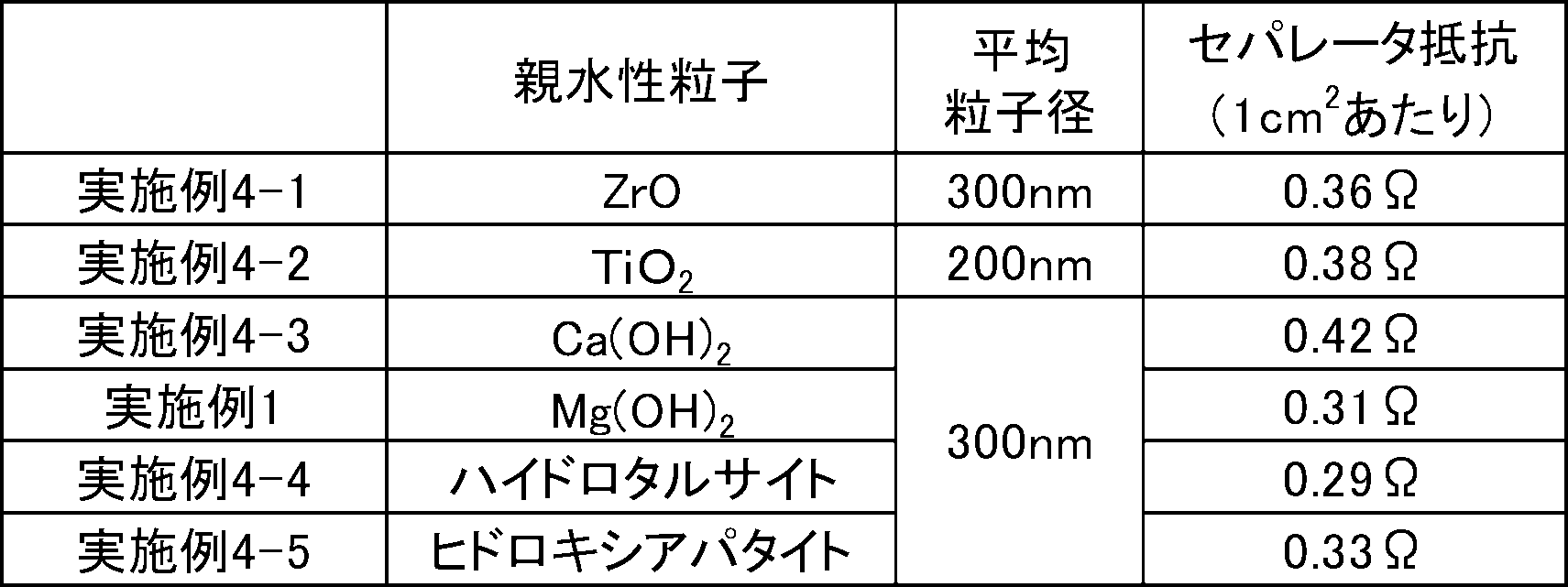
- Table 3 shows the results of experiments in which the following particles were subjected to a water permeability test to determine their hydrophobicity/hydrophilicity.
- the separator contains hydrophobic particles and hydrophilic particles each at a certain ratio or more, and the content of the binder component is When the ratio is less than a certain ratio, the ionic conductivity is sufficient, and the durability is excellent, and especially when the electrochemical device includes an electrode that undergoes a morphological change due to charge and discharge, a short circuit between electrodes due to dendrites. It was found that the above can be sufficiently suppressed, and as a result, the electrochemical device can have a long life. Among them, it was found that the separator of Example 1 using magnesium hydroxide as the hydrophilic particles was remarkably excellent in durability.
Landscapes
- Chemical & Material Sciences (AREA)
- Chemical Kinetics & Catalysis (AREA)
- Electrochemistry (AREA)
- General Chemical & Material Sciences (AREA)
- Cell Separators (AREA)
Abstract
本発明は、電気化学素子をより長寿命化する方法を提供する。 本発明は、電気化学素子に用いられるセパレータであって、該セパレータは、疎水性粒子、親水性粒子、及び、所望により結着成分を含み、疎水性粒子/(親水性粒子及び結着成分)の体積割合は、20/80を超え、親水性粒子/(疎水性粒子及び結着成分)の体積割合は、20/80を超え、結着成分/(疎水性粒子及び親水性粒子)の体積割合は、30/70未満である電気化学素子用セパレータである。
Description
本発明は、電気化学素子用セパレータに関する。より詳しくは、電池、コンデンサ、キャパシタ、センサ、電気分解装置等の電気化学素子に用いられるセパレータに関する。
近年、小型携帯機器から自動車等大型用途まで多くの産業において、電池の重要性が急速に高まっており、主にその容量、エネルギー密度や二次電池化の面において優位性を持つ新たな電池系が種々開発されている。また、電池以外の電気化学素子についても、各々の面において優位性を持つものが種々開発されている。
例えば、充電時に生じる亜鉛の針状結晶(デンドライト)を阻止するバリヤー層として作用する酸化マグネシウムの多孔質の層を密着させた亜鉛アルカリ二次電池が開示されている(例えば、特許文献1参照)。
上記特許文献1に記載の酸化マグネシウムの多孔質の層は、電池をより長寿命化するための更なる工夫の余地があるものであった。また、電池以外の電気化学素子においても、より長寿命化することが望まれている。
本発明は、上記現状に鑑みてなされたものであり、電気化学素子をより長寿命化する方法を提供することを目的とする。
本発明者らは、電気化学素子をより長寿命化する方法について種々検討し、電気化学素子に用いるセパレータに着目した。そして、本発明者らは、疎水性粒子及び親水性粒子をそれぞれ一定割合以上含み、かつ結着成分の含有量が一定割合未満の電気化学素子用セパレータとすると、電気化学素子を長寿命化できることを見出し、上記課題をみごとに解決することができることに想到し、本発明に到達したものである。
すなわち本発明は、電気化学素子に用いられるセパレータであって、該セパレータは、疎水性粒子、親水性粒子、及び、所望により結着成分を含み、疎水性粒子/(親水性粒子及び結着成分)の体積割合は、20/80を超え、親水性粒子/(疎水性粒子及び結着成分)の体積割合は、20/80を超え、結着成分/(疎水性粒子及び親水性粒子)の体積割合は、30/70未満である電気化学素子用セパレータである。
本発明は、上述の構成よりなり、電気化学素子を長寿命化することができる。
以下に本発明を詳述する。
なお、以下において記載する本発明の個々の好ましい形態を2つ以上組み合わせたものもまた、本発明の好ましい形態である。
なお、以下において記載する本発明の個々の好ましい形態を2つ以上組み合わせたものもまた、本発明の好ましい形態である。
<本発明の電気化学素子用セパレータ>
本発明の電気化学素子用セパレータは、正極と負極とを隔離しつつ、正極と負極との間のイオン伝導性を確保する部材であるが、上述したように疎水性粒子及び親水性粒子をそれぞれ一定割合以上含み、かつ結着成分の含有量が一定割合未満のものである。
本発明の電気化学素子用セパレータは、正極と負極とを隔離しつつ、正極と負極との間のイオン伝導性を確保する部材であるが、上述したように疎水性粒子及び親水性粒子をそれぞれ一定割合以上含み、かつ結着成分の含有量が一定割合未満のものである。
本発明の電気化学素子用セパレータは、その構成により耐久性に優れるものであり、特に、充放電に伴って形態変化が起こる電極を含む電気化学素子に用いられる場合に、疎水性粒子を一定割合以上含むことにより、本発明の電気化学素子の使用時において、疎水性粒子の撥水性により、セパレータ中の実質的な電解液量が制限されることになり、セパレータ中の遊離の活物質由来のイオン(例えば、亜鉛酸イオン)濃度が低いものとなるため、活物質成分(例えば、亜鉛成分)の溶解析出反応が起こる過程で生じるデンドライトの成長を充分に抑制することができ、電気化学素子を長寿命化することができる。また、本発明の電気化学素子用セパレータは、親水性粒子を一定割合以上含み、結着成分の含有量が一定割合未満であることにより、親水性粒子表面がイオン伝導パスとなるとともに、結着成分が粒子間を結着する際に粒子間の空隙の大部分を埋めてしまうことを充分に防止でき、セパレータのイオン伝導性を充分に高いものとすることができる。電気化学素子内部におけるイオン伝導性を充分に高いものとし、内部抵抗の低い電気化学素子とすることで、電気化学素子を適切に駆動することができ、長寿命化に寄与する。なお、疎水性粒子は、比表面積が小さな繊維状ではなく粒子形状である点で、上記の撥水性を顕著に発揮できる。親水性粒子も同様に、粒子形状であることでセパレータのイオン伝導性を非常に優れたものとすることができる。
上記疎水性粒子/(親水性粒子及び結着成分)の体積割合は、25/75以上であることが好ましく、37/63以上であることがより好ましい。なお、該疎水性粒子/(親水性粒子及び結着成分)の体積割合は、上記親水性粒子/(疎水性粒子及び結着成分)の体積割合が20/80を超えることから、80/20未満であり、好ましくは70/30以下である。
上記親水性粒子/(疎水性粒子及び結着成分)の体積割合は、30/70以上であることが好ましい。なお、該親水性粒子/(疎水性粒子及び結着成分)の体積割合は、上記疎水性粒子/(親水性粒子及び結着成分)の体積割合が20/80を超えることから、80/20未満であり、好ましくは75/25以下であり、より好ましくは63/37以下である。
上記結着成分/(疎水性粒子及び親水性粒子)の体積割合は、20/80以下であることが好ましく、10/90以下であることがより好ましい。なお、結着成分は任意成分であり、上記結着成分/(疎水性粒子及び親水性粒子)の体積割合の下限値は、好ましくは0/100であり、より好ましくは0.1/99.9であり、さらに好ましくは1/99である。
以下では、本発明の電気化学素子用セパレータに含まれる疎水性粒子、親水性粒子、任意成分である結着成分等について順に説明する。
〔疎水性粒子〕
本発明の電気化学素子用セパレータは、疎水性粒子を含む。本明細書中、疎水性粒子とは、下記透水性試験により算出される透水量が0.01g以下である粒子をいう。疎水性粒子は、該透水量が0.01g以下である限り特に限定されず、例えば、粒子全体が疎水性材料で構成された粒子であってもよいし、表面が疎水性材料で被覆された粒子であってもよい。
上記疎水性粒子における透水量は、0.001g以下であることが好ましい。
なお、上記疎水性粒子における透水量の下限値は、0gである。
疎水性粒子は、独立した粒子形状を保つことが好ましい。
本発明の電気化学素子用セパレータは、疎水性粒子を含む。本明細書中、疎水性粒子とは、下記透水性試験により算出される透水量が0.01g以下である粒子をいう。疎水性粒子は、該透水量が0.01g以下である限り特に限定されず、例えば、粒子全体が疎水性材料で構成された粒子であってもよいし、表面が疎水性材料で被覆された粒子であってもよい。
上記疎水性粒子における透水量は、0.001g以下であることが好ましい。
なお、上記疎水性粒子における透水量の下限値は、0gである。
疎水性粒子は、独立した粒子形状を保つことが好ましい。
<透水性試験方法>
図8に示されるように、室温、常圧下で、内径1.5cmの円筒形容器6の下部に、親水処理(フッ素処理)済ポリプロピレン製不織布8を設置し、更に、水吸収体としてαセルロースからなる、3cm×3cm、厚み1mm、重量400mgのろ紙7を設置し、円筒形容器6の上部付近から試料紛体5(1g)を静かに投入する。その後、水9(2g)を円筒形容器6の上部付近から静かに投入し、1時間経過後にろ紙7に吸収された水分量を計測し、1時間あたりの透水量を算出する。水分量は、ろ紙7の重量変化から計測することができる。なお、親水処理済ポリプロピレン製不織布8は、ろ紙7に試料粉体5が付着して重量誤差を生じないように、ろ紙7と試料粉体5との間に挿入したものである。また、試料がディスパージョンのような形態の場合は、円筒形容器6の下部に蓋をしてディスパージョンの固形分重量が1gになるように投入し、乾燥後に下部の蓋を外し親水処理済ポリプロピレン製不織布8及びろ紙7をセットした後、上述したように水9を投入して透水性試験を実施する。
なお、各種粒子について透水性試験を実施した結果を実施例に示す。
なお、疎水性粒子は、その表面のガラス転移温度が60℃以上であることが好ましく、その全体のガラス転移温度が60℃以上であることがより好ましい。本明細書中、ガラス転移温度は、ポリマー等の材料をガラス板に塗布し、120℃で1時間乾燥して得られた乾燥体について、示差走査熱量計(装置名:熱分析装置DSC3100S、BRVKER)を用いて測定されるものである。
以下では、まず、主として粒子全体が疎水性材料で構成された粒子について説明するが、表面が疎水性材料で被覆された粒子の疎水性材料部分についても同様のことが言える。
上記疎水性粒子は、ポリマー粒子(有機ポリマー粒子)であることが好ましい。該ポリマー粒子を構成するポリマーとしては、種々の疎水性材料を好適に用いることができ、熱可塑性、熱硬化性のいずれであってもよく、例えば、含ハロゲン原子エチレン系ポリマー、ポリスルホン系ポリマー、ポリエーテルケトン等が挙げられるが、中でも、含ハロゲン原子エチレン系ポリマー及び/又はポリスルホン系ポリマーであることが好ましい。
上記疎水性粒子は、ポリマー粒子(有機ポリマー粒子)であることが好ましい。該ポリマー粒子を構成するポリマーとしては、種々の疎水性材料を好適に用いることができ、熱可塑性、熱硬化性のいずれであってもよく、例えば、含ハロゲン原子エチレン系ポリマー、ポリスルホン系ポリマー、ポリエーテルケトン等が挙げられるが、中でも、含ハロゲン原子エチレン系ポリマー及び/又はポリスルホン系ポリマーであることが好ましい。
上記含ハロゲン原子エチレン系ポリマーは、ポリエチレンの水素原子の少なくとも一部がハロゲン原子に置換された構造のものであり、中でもポリエチレンの水素原子の少なくとも一部がフッ素原子に置換された構造の含フッ素原子エチレン系ポリマーであることが好ましく、例えば、ポリフッ化ビニリデン、ポリテトラフルオロエチレン等が好適なものとして挙げられる。
上記ポリスルホン系ポリマーは、スルホニル基を繰り返し単位に有するポリマーを言い、例えばポリスルホン(PSU)、ポリエーテルスルホン(PESU)、ポリフェニルスルホン(PSSU)が挙げられる。
上記ポリエーテルケトンは、エーテル結合及びケトン結合を有するポリマーであり、例えばポリエーテルケトンケトン、ポリエーテルエーテルケトン等が挙げられる。
上記ポリスルホン系ポリマーは、スルホニル基を繰り返し単位に有するポリマーを言い、例えばポリスルホン(PSU)、ポリエーテルスルホン(PESU)、ポリフェニルスルホン(PSSU)が挙げられる。
上記ポリエーテルケトンは、エーテル結合及びケトン結合を有するポリマーであり、例えばポリエーテルケトンケトン、ポリエーテルエーテルケトン等が挙げられる。
上記ポリマーは、ポリマーが含む構成単位を形成するモノマー成分をラジカル発生剤の存在下、共重合し、必要に応じてこれをグラフト変性等することにより製造することができる。
モノマー成分の重合方法としては特に限定されず、例えば、水溶液重合法、乳化重合法、逆相懸濁重合法、懸濁重合法、溶液重合法、塊状重合法等の方法が挙げられる。
モノマー成分の重合方法としては特に限定されず、例えば、水溶液重合法、乳化重合法、逆相懸濁重合法、懸濁重合法、溶液重合法、塊状重合法等の方法が挙げられる。
上記疎水性粒子の形状としては、微粉状、粉状、粒状、顆粒状、鱗片状、多面体状、ロッド状、曲面含有状等が挙げられる。
上記疎水性粒子は、平均粒子径が50nm以上であることが好ましい。該平均粒子径は、100nm以上であることがより好ましく、200nm以上であることが更に好ましい。また、該平均粒子径は、100μm以下であることが好ましく、50μm以下であることがより好ましく、10μm以下であることが更に好ましい。
平均粒子径は、体積基準の粒度分布における平均粒子径であり、疎水性粒子水分散液約10mLをガラスセルに採取し、これを動的光散乱法による粒度分布測定器(パーティクルサイジングシステムズ〔Particle Sizing Systems〕社製、商品名:NICOMP Model 380)を用いて測定されるものである。
上記疎水性粒子は、アスペクト比(縦/横)が1以上であればよい。また、該アスペクト比(縦/横)は、8以下であることが好ましい。該アスペクト比(縦/横)は、より好ましくは5以下であり、更に好ましくは2以下であり、特に好ましくは1.5以下である。
上記アスペクト比(縦/横)は、SEMにより観察した粒子の形状から求めることができる。例えば、上記粒子が直方体状の場合は、最も長い辺を縦、2番目に長い辺を横として、縦の長さを横の長さで除することにより求めることができる。その他の形状の場合には、アスペクト比が最も大きくなるように、ある一つの部分を底面に置き、それをアスペクト比が最も大きくなるような方向から投影した時にできる二次元の形において、ある一点から最も離れた一点の長さを測定し、その最も長いものを縦、縦の中心点を通る直線のうち最も短いものを横として、縦の長さを横の長さで除することにより求めることができる。
なお、アスペクト比(縦/横)が上述のような範囲の粒子は、例えば、そのようなアスペクト比を有する粒子を選択する方法や、粒子を製造する段階で調製条件を最適化し、該粒子を選択的に得る方法等により得ることが可能である。
〔親水性粒子〕
上記セパレータは、親水性粒子を含む。本明細書中、親水性粒子とは、上記透水性試験により算出される透水量が0.01gを超える粒子であり、通常、ガラス転移温度を有さない無機化合物粒子である。親水性粒子は、該透水量が0.01gを超える限り特に限定されず、例えば、粒子全体が親水性材料で構成された粒子であってもよいし、表面が親水性材料で被覆された粒子であってもよい。
上記親水性粒子における透水量は、0.1g以上であることが好ましい。
なお、上記親水性粒子における透水量の上限値は、2gである。
上記セパレータは、親水性粒子を含む。本明細書中、親水性粒子とは、上記透水性試験により算出される透水量が0.01gを超える粒子であり、通常、ガラス転移温度を有さない無機化合物粒子である。親水性粒子は、該透水量が0.01gを超える限り特に限定されず、例えば、粒子全体が親水性材料で構成された粒子であってもよいし、表面が親水性材料で被覆された粒子であってもよい。
上記親水性粒子における透水量は、0.1g以上であることが好ましい。
なお、上記親水性粒子における透水量の上限値は、2gである。
以下では、まず、主として粒子全体が親水性材料で構成された粒子について説明するが、表面が親水性材料で被覆された粒子の親水性材料部分についても同様のことが言える。
上記親水性粒子は、上述したように、無機化合物粒子であることが好ましい。無機化合物粒子を構成する無機化合物としては、種々の親水性材料を好適に用いることができるが、例えば、酸化物、水酸化物、層状複水酸化物、及び、リン酸化合物からなる群より選択される少なくとも1種であることが好ましい。なお、本明細書中、水酸化物は、ヒドロキシ基を有する化合物であって、層状複水酸化物以外のものを言う。
上記親水性粒子は、上述したように、無機化合物粒子であることが好ましい。無機化合物粒子を構成する無機化合物としては、種々の親水性材料を好適に用いることができるが、例えば、酸化物、水酸化物、層状複水酸化物、及び、リン酸化合物からなる群より選択される少なくとも1種であることが好ましい。なお、本明細書中、水酸化物は、ヒドロキシ基を有する化合物であって、層状複水酸化物以外のものを言う。
上記酸化物としては、例えば、酸化リチウム、酸化ナトリウム、酸化カリウム、酸化マグネシウム、酸化カルシウム、酸化バリウム、酸化スカンジウム、酸化イットリウム、酸化ランタノイド、酸化チタン、酸化ジルコニウム、酸化ニオブ、酸化ルテニウム、酸化ニッケル、酸化パラジウム、酸化銅、酸化カドミウム、酸化ホウ素、酸化アルミニウム、酸化ガリウム、酸化インジウム、酸化タリウム、酸化ケイ素、酸化ゲルマニウム、酸化スズ、酸化鉛、酸化リン、酸化ビスマス等が挙げられ、これらの1種又は2種以上を使用できる。中でも、成膜時の分散液中やアルカリ性条件下の電気化学素子内であっても安定なものが好ましく、例えば酸化マグネシウム、酸化カルシウム、酸化チタン、酸化ジルコニウム、酸化アルミニウムが好ましく、酸化マグネシウム、酸化チタン、酸化ジルコニウムがより好ましい。なお、酸化ジルコニウムは、例えば、イットリウム、スカンジウム、イッテルビウム等の元素を固溶化したものであってもよく、酸素欠陥を持つものであってもよい。
上記水酸化物としては、例えば、水酸化リチウム、水酸化ナトリウム、水酸化カリウム、水酸化マグネシウム、水酸化カルシウム、水酸化バリウム、水酸化スカンジウム、水酸化イットリウム、水酸化ランタノイド、水酸化チタン、水酸化ジルコニウム、水酸化ニオブ、水酸化ルテニウム、水酸化ニッケル、水酸化パラジウム、水酸化銅、水酸化カドミウム、ホウ酸、水酸化アルミニウム、水酸化ガリウム、水酸化インジウム、水酸化タリウム、ケイ酸、水酸化ゲルマニウム、水酸化スズ、水酸化鉛、リン酸、水酸化ビスマス等が挙げられ、これらの1種又は2種以上を使用できる。中でも、アルカリ性条件下での溶解度が低いものが好ましく、例えば水酸化マグネシウム、水酸化カルシウム、水酸化チタン、水酸化ジルコニウムが好ましく、水酸化マグネシウムがより好ましい。
上記層状複水酸化物は、下記一般式:
[M1 1-xM2 x(OH)2](An-)x/n・mH2O
(M1は、Mg、Fe、Zn、Ca、Li、Ni、Co、Cu、Mnのいずれかである二価金属イオンを表す。M2は、Al、Fe、Mn、Co、Cr、Inのいずれかである三価金属イオンを表す。An-は、Cl-、NO3 -、CO3 2-、COO-等の1価以上、3価以下のアニオンを表す。中でも、An-は、2価以下のアニオンを表すことが好ましい。mは0以上の数であり、nは1以上、3以下の数である。xは0.20以上、0.40以下の数である。)に代表される化合物であり、このような層状複水酸化物としては、例えば、ハイドロタルサイト、マナッセイト、モツコレアイト、スティッヒタイト、ショグレナイト、バーバートナイト、パイロアウライト、イオマイト、クロロマガルミナイト、ハイドロカルマイト、グリーン ラスト1、ベルチェリン、タコバイト、リーベサイト、ホネサイト、イヤードライト、メイキセネライト等が挙げられ、これらの1種又は2種以上を使用できる。中でも、工業的に利用が容易である点で、前記一般式におけるM1がMg、M2がAlであるハイドロタルサイトが好ましい。
なお、これら層状水酸化物は、例えば、150℃以上、900℃以下で焼成することにより脱水した化合物や層間内の陰イオンを分解させた化合物、層間内の陰イオンを水酸化物イオン等に交換した化合物であってもよい。
上記層状複水酸化物には、水酸基、アミノ基、カルボキシ基、シラノール基等の官能基を持つ化合物が配位していてもよい。また、上記層状複水酸化物は層間内に有機物を有していてもよい。
上記リン酸化合物としては、例えばヒドロキシアパタイト(Ca10(PO4)6(OH)2)、ヒドロキシアパタイトのカルシウムイオンの一部又は全部をマグネシウムに置換したマグネシウムヒドロキシアパタイト、ストロンチウムに置換したストロンチウムヒドロキシアパタイト、バリウムに置換したバリウムヒドロキシアパタイト等が挙げられる。中でも、ヒドロキシアパタイト、マグネシウムヒドロキシアパタイトが好ましい。
上記無機化合物は、中でも、マグネシウム含有化合物であることが好ましい。また、該無機化合物としては、水酸化物、層状複水酸化物、リン酸化合物が好ましく、層状複水酸化物及び/又は水酸化物であることがより好ましい。上記無機化合物は、セパレータの強度をより優れたものとする観点からは、水酸化物であることが更に好ましく、セパレータのイオン伝導性をより優れたものとする観点からは、層状複水酸化物、水酸化マグネシウムであることが更に好ましく、セパレータの耐久性をより優れたものとする観点からは、水酸化マグネシウムであることが特に好ましい。
上記親水性粒子の形状としては、微粉状、粉状、粒状、顆粒状、鱗片状、多面体状、ロッド状、曲面含有状等が挙げられる。
上記親水性粒子は、平均粒子径が2μm以下であるものが好ましい。該平均粒子径は、より好ましくは1μm以下であり、更に好ましくは0.5μm以下である。また、該平均粒子径は、0.001μm以上であることが好ましく、10nm以上であることがより好ましく、100nm以上であることが更に好ましい。
上記平均粒子径とは、体積基準の粒度分布における平均粒子径であり、親水性粒子を分散媒(0.2%ヘキサメタりん酸ナトリウム含有イオン交換水)で希釈し、得られた希釈液約10mLをガラスセルに採取し、これを動的光散乱法による粒度分布測定器(パーティクルサイジングシステムズ〔Particle Sizing Systems〕社製、商品名:NICOMP Model 380)を用いて測定されるものである。
なお、体積平均粒子径が上記のような範囲の粒子は、例えば、粒子をボールミル等により粉砕し、得られた粗粒子を分散剤に分散させて所望の粒子径にした後に乾固する方法や、該粗粒子をふるい等にかけて粒子径を選別する方法のほか、粒子を製造する段階で調製条件を最適化し、所望の粒子径の(ナノ)粒子を得る方法等により製造することが可能である。
上記親水性粒子は、アスペクト比(縦/横)が1以上であればよい。また、該アスペクト比(縦/横)は、8以下であることが好ましい。該アスペクト比(縦/横)は、より好ましくは5以下であり、更に好ましくは2以下であり、特に好ましくは1.5以下である。
上記アスペクト比(縦/横)の求め方は、上述した通りである。
また、アスペクト比(縦/横)が上述のような範囲の粒子は、上述した方法により得ることができる。
上記アスペクト比(縦/横)の求め方は、上述した通りである。
また、アスペクト比(縦/横)が上述のような範囲の粒子は、上述した方法により得ることができる。
上記セパレータは、例えば、上述したように、疎水性粒子としてポリマー粒子を含み、親水性粒子として無機化合物粒子を含むアニオン伝導性膜であることが好ましい。
本明細書中では、アニオン伝導性膜は、電気化学素子の反応に関与する水酸化物イオン等のアニオンを透過する膜であって、ポリマー粒子と、無機化合物粒子を含むものを言う。上記アニオン伝導性膜は、後述する無機化合物粒子等の作用により、透過するアニオンの選択性を有する。なお、当該アニオンの選択性は、水酸化物イオン等のアニオンは透過しやすく、アニオンであってもイオン半径の大きな、活物質に由来する金属含有イオン(例えば、Zn(OH)4
2-)等の透過は充分に防止する。本明細書中、アニオン伝導性とは、水酸化物イオン等のイオン半径の小さなアニオンを充分に透過すること、ないし、当該アニオンの透過性能を意味する。金属含有イオン等のイオン半径の大きなアニオンは、より透過しにくいものであり、全く透過しなくても構わない。
〔結着成分〕
上記セパレータは更に、結着成分を含んでいてもよい。結着成分は、通常、ガラス転移温度が60℃未満である成分をいい、粒子間を結着することで、セパレータの構造安定性に寄与できるものである。結着成分は、ガラス転移温度が50℃以下であることが好ましい。
また結着成分は、非粒子状であることが好ましい。
更に、結着成分は、周囲の他の成分(疎水性粒子、親水性粒子、多孔質支持体等)と結着していることが好ましい。
上記セパレータは更に、結着成分を含んでいてもよい。結着成分は、通常、ガラス転移温度が60℃未満である成分をいい、粒子間を結着することで、セパレータの構造安定性に寄与できるものである。結着成分は、ガラス転移温度が50℃以下であることが好ましい。
また結着成分は、非粒子状であることが好ましい。
更に、結着成分は、周囲の他の成分(疎水性粒子、親水性粒子、多孔質支持体等)と結着していることが好ましい。
上記結着成分は、ガラス転移温度が60℃未満である非結晶性のバインダーポリマーであることが好ましい。非結晶性であることにより、周囲の部材と結合を作りやすく、結着成分として好適に機能する。なお、バインダーポリマーは、繊維状であることが好ましい。
上記バインダーポリマーとしては、共役ジエン系ポリマー、(メタ)アクリル系ポリマーが挙げられ、中でも、共役ジエン系ポリマーが好ましい。
上記バインダーポリマーとしては、共役ジエン系ポリマー、(メタ)アクリル系ポリマーが挙げられ、中でも、共役ジエン系ポリマーが好ましい。
上記共役ジエン系ポリマーは、共役ジエン系モノマー由来のモノマー単位を有するものである。
上記共役ジエン系ポリマーとしては、スチレン-ブタジエン系ポリマー、カルボキシ変性スチレン-ブタジエン系ポリマー、ポリブタジエン系ポリマー、カルボキシ変性ポリブタジエン系ポリマー、ポリイソプレン系ポリマー、カルボキシ変性ポリイソプレン系ポリマー、アクリロニトリル-ブタジエン系ポリマー、カルボキシ変性アクリロニトリル-ブタジエン系ポリマー等の1種又は2種以上を好適に用いることができる。これらの中でも、スチレン-ブタジエン系ポリマー、カルボキシ変性スチレン-ブタジエン系ポリマーが好ましく、特にカルボキシ変性スチレン-ブタジエン系ポリマーが好ましい。
上記共役ジエン系ポリマーとしては、スチレン-ブタジエン系ポリマー、カルボキシ変性スチレン-ブタジエン系ポリマー、ポリブタジエン系ポリマー、カルボキシ変性ポリブタジエン系ポリマー、ポリイソプレン系ポリマー、カルボキシ変性ポリイソプレン系ポリマー、アクリロニトリル-ブタジエン系ポリマー、カルボキシ変性アクリロニトリル-ブタジエン系ポリマー等の1種又は2種以上を好適に用いることができる。これらの中でも、スチレン-ブタジエン系ポリマー、カルボキシ変性スチレン-ブタジエン系ポリマーが好ましく、特にカルボキシ変性スチレン-ブタジエン系ポリマーが好ましい。
上記共役ジエン系ポリマーは、脂肪族共役ジエン系モノマー由来のモノマー単位、芳香族ビニルモノマー由来のモノマー単位、カルボキシ基及び/又はその塩であるカルボキシレート基を有する不飽和モノマー由来のモノマー単位以外の、その他の不飽和モノマー由来のモノマー単位を有していてもよい。
上記共役ジエン系ポリマー100質量%中、その他の不飽和モノマー由来のモノマー単位の質量割合は、30質量%以下であることが好ましく、5質量%以下であることがより好ましく、0.1質量%以下であることが更に好ましい。
上記共役ジエン系ポリマー100質量%中、その他の不飽和モノマー由来のモノマー単位の質量割合は、30質量%以下であることが好ましく、5質量%以下であることがより好ましく、0.1質量%以下であることが更に好ましい。
上記(メタ)アクリル系ポリマーは、(メタ)アクリロイル基を有するモノマー由来のモノマー単位を有するものであればよいが、代表的なものとしては(メタ)アクリル酸エステルモノマー由来のモノマー単位を主体とする(メタ)アクリル酸エステル系ポリマーが挙げられる。
(メタ)アクリル酸エステルモノマー由来のモノマー単位を主体とするとは、(メタ)アクリル酸エステル系ポリマー100質量%中、(メタ)アクリル酸エステルモノマー由来のモノマー単位の含有量が50質量%以上であることを言う。
(メタ)アクリル酸エステルモノマーは、具体的には、(メタ)アクリル酸メチル、(メタ)アクリル酸エチル、(メタ)アクリル酸プロピル、(メタ)アクリル酸n-ブチル、(メタ)アクリル酸イソブチル、(メタ)アクリル酸t-ブチル、(メタ)アクリル酸ペンチル、(メタ)アクリル酸ヘキシル、(メタ)アクリル酸ヘプチル、(メタ)アクリル酸オクチル、(メタ)アクリル酸2-エチルヘキシル、(メタ)アクリル酸ノニル、(メタ)アクリル酸デシル等が挙げられる。
(メタ)アクリル酸エステルモノマーは、具体的には、(メタ)アクリル酸メチル、(メタ)アクリル酸エチル、(メタ)アクリル酸プロピル、(メタ)アクリル酸n-ブチル、(メタ)アクリル酸イソブチル、(メタ)アクリル酸t-ブチル、(メタ)アクリル酸ペンチル、(メタ)アクリル酸ヘキシル、(メタ)アクリル酸ヘプチル、(メタ)アクリル酸オクチル、(メタ)アクリル酸2-エチルヘキシル、(メタ)アクリル酸ノニル、(メタ)アクリル酸デシル等が挙げられる。
上記(メタ)アクリル系ポリマーは、(メタ)アクリル酸エステルモノマー由来のモノマー単位以外に、カルボキシ基及び/又はその塩であるカルボキシレート基を有する不飽和モノマー由来のモノマー単位や、その他の不飽和モノマー由来のモノマー単位を有していてもよい。
上記(メタ)アクリル系ポリマー100質量%中、その他の不飽和モノマー由来のモノマー単位の質量割合は、30質量%以下であることが好ましく、5質量%以下であることがより好ましく、0.1質量%以下であることが更に好ましい。
上記(メタ)アクリル系ポリマー100質量%中、その他の不飽和モノマー由来のモノマー単位の質量割合は、30質量%以下であることが好ましく、5質量%以下であることがより好ましく、0.1質量%以下であることが更に好ましい。
上記バインダーポリマーは、上述したように繊維状であることが好ましく、熱や圧力等により繊維化された状態になってもよい。ポリマーの繊維化により、セパレータの強度、アニオン伝導度等を好適に調節することができる。
〔多孔質支持体〕
本発明の電気化学素子用セパレータは、更に、ポリオレフィン系ポリマー等からなる多孔質支持体(多孔質基材)を有し、多孔質支持体に疎水性粒子、親水性粒子、及び、必要に応じて結着成分の混合物(分散液)が含浸した樹脂含浸層であってもよく、多孔質基材に該混合物を接触させ、必要に応じて混合物を乾燥させて得られる積層構造のものであってもよい。
本発明の電気化学素子用セパレータは、更に、ポリオレフィン系ポリマー等からなる多孔質支持体(多孔質基材)を有し、多孔質支持体に疎水性粒子、親水性粒子、及び、必要に応じて結着成分の混合物(分散液)が含浸した樹脂含浸層であってもよく、多孔質基材に該混合物を接触させ、必要に応じて混合物を乾燥させて得られる積層構造のものであってもよい。
上記多孔質支持体は、特に限定されないが、例えばポリエチレン、ポリプロピレン、エチレン-プロピレン共重合体、環状ポリオレフィン系ポリマー等のポリオレフィン系ポリマー;ビニロン等のポリビニルアルコール系ポリマー;脂肪族ポリアミド;芳香族ポリアミド;スチレン系ポリマー;ポリエステル系ポリマー;ポリフェニレンサルファイド系ポリマー等の樹脂材料により構成された不織布、織布、微多孔質フィルム等が好適なものとして挙げられ、中でも、ポリオレフィン系ポリマー、ポリビニルアルコール系ポリマーがより好ましい。
上記セパレータは、本発明に係る分散液を多孔質支持体に含浸させて得られる樹脂含浸層と多孔質支持体とが少なくとも部分的に一体化したものである。該セパレータでは、本発明に係る分散液の固形分が多孔質支持体中の空孔の少なくとも一部を埋めている。
上記セパレータは、本発明に係る分散液を多孔質支持体に含浸させて得られる樹脂含浸層と多孔質支持体とが少なくとも部分的に一体化したものである。該セパレータでは、本発明に係る分散液の固形分が多孔質支持体中の空孔の少なくとも一部を埋めている。
上記多孔質支持体の質量割合は、上記セパレータ100質量%中、5質量%以上であることが好ましく、10質量%以上であることがより好ましく、15質量%以上であることが更に好ましい。また、該質量割合は、60質量%以下であることが好ましく、50質量%以下であることがより好ましく、40質量%以下であることが更に好ましい。
上記多孔質支持体の密度は、塗料含浸時の観点から、0.05g/cm3以上が好ましく、0.1g/cm3以上がより好ましい。また、該密度は、2.0g/cm3以下が好ましく、1.0g/cm3以下が更に好ましい。
上記多孔質支持体の膜厚は、電気化学素子性能や強度を優れたものとしたり、含浸時に無機成分との分離を抑えたりする観点から、300μm以下が好ましく、200μm以下がより好ましい。また、該膜厚は、5μm以上が好ましく、20μm以上がより好ましい。
〔その他の成分〕
本発明の電気化学素子用セパレータは更に、従来公知の分散剤、増粘剤、導電性カーボン、導電性セラミックス等のその他の成分を含んでいてもよい。
上記セパレータにおけるその他の成分の含有割合は、セパレータの強度の観点からセパレータ100質量%中、10質量%以下であることが好ましい。より好ましくは5質量%以下であり、更に好ましくは1質量%以下であり、特に好ましくは0.1質量%以下である。
本発明の電気化学素子用セパレータは更に、従来公知の分散剤、増粘剤、導電性カーボン、導電性セラミックス等のその他の成分を含んでいてもよい。
上記セパレータにおけるその他の成分の含有割合は、セパレータの強度の観点からセパレータ100質量%中、10質量%以下であることが好ましい。より好ましくは5質量%以下であり、更に好ましくは1質量%以下であり、特に好ましくは0.1質量%以下である。
本発明の電気化学素子用セパレータは、平均膜厚が10μm~1mmであることが好ましい。10μm以上であると耐久性をより優れたものとすることができる。また、1mm以下であるとコスト面から有利となる上、イオンの透過の能力も充分に優れる。該平均膜厚は、20μm以上であることがより好ましい。また、該平均膜厚は、500μm以下であることがより好ましい。
上記平均膜厚は、デジマチックマイクロメーター(ミツトヨ社製)を用いて任意の10点を測定した平均値である。
上記平均膜厚は、デジマチックマイクロメーター(ミツトヨ社製)を用いて任意の10点を測定した平均値である。
本発明の電気化学素子用セパレータは、ガス透過性であることが好ましい。
ガス透過性とは、透気度がガーレー値で10000秒以下であればよい。該ガーレー値は、9500秒以下であることが好ましい。
また上記ガーレー値は、500秒以上であることが好ましく、1000秒以上であることがより好ましい。
上記ガーレー値は、実施例に記載のガーレー法により測定されるものである。ガーレー値は、気体の通過しやすさを表す指標であり、値が大きいほど気体を通しにくい。
なお、上記ガーレー値は、セパレータが複数の層が積層された積層体である場合は、積層体について測定されたガーレー値である。
ガス透過性とは、透気度がガーレー値で10000秒以下であればよい。該ガーレー値は、9500秒以下であることが好ましい。
また上記ガーレー値は、500秒以上であることが好ましく、1000秒以上であることがより好ましい。
上記ガーレー値は、実施例に記載のガーレー法により測定されるものである。ガーレー値は、気体の通過しやすさを表す指標であり、値が大きいほど気体を通しにくい。
なお、上記ガーレー値は、セパレータが複数の層が積層された積層体である場合は、積層体について測定されたガーレー値である。
本発明の電気化学素子用セパレータは、空隙率が20体積%以上であることが好ましく、30体積%以上であることがより好ましい。また、該空隙率は、90体積%以下であることが好ましく、80体積%以下であることがより好ましい。
上記空隙率は、セパレータの体積に対するセパレータの空隙の体積で表されるものであり、水銀ポロシメーターにより測定することができる。
上記空隙率は、セパレータの体積に対するセパレータの空隙の体積で表されるものであり、水銀ポロシメーターにより測定することができる。
本発明の電気化学素子用セパレータの作製方法の一例としては、先ず、親水性粒子と公知の分散剤と水とを混合し、分散装置を用いて親水性粒子の分散液を作製する。分散液の作製には、超音波やボールミル、ペイントシェーカー等の分散装置を用いることができる。該分散液に、同様に分散状態(ディスパージョン状態)の疎水成分(疎水性粒子)と結着成分を混合する。この時の混合液の固形分濃度を例えば60質量%以下に調整することで、混合時に塗料にせん断応力がかからない粘度にすることが好ましい。混合は、疎水性粒子等の粒子形態を維持できる程度にせん断応力等が低いマイルドな条件で行えばよく、例えば撹拌羽を用いて塗料を撹拌して混合することができる。撹拌には、その他、マグネチックスターラーや振動撹拌機等も用いることができる。なお、ニーダーのように混合時のせん断応力が高い混合方法を用いると、例えば疎水成分がポリマー粒子である場合に、ポリマーの種類(材質、熱可塑性樹脂か架橋された樹脂か等)によるが、ポリマーによってはその粒子形態の大部分が繊維形態等の粒子以外の形態に変化してしまう。
塗料を溜めた液相の中に、多孔質支持体(例えば、不織布)を導入し、充分に含浸させた後、引き上げながら乾燥させ、シート化する。
なお、本発明の電気化学素子用セパレータは、上記混合液を剥離基材上に塗工した後、多孔質支持体に接触させ、膜を乾燥させたうえで剥離基材から剥離して得ることもできる。
塗料を溜めた液相の中に、多孔質支持体(例えば、不織布)を導入し、充分に含浸させた後、引き上げながら乾燥させ、シート化する。
なお、本発明の電気化学素子用セパレータは、上記混合液を剥離基材上に塗工した後、多孔質支持体に接触させ、膜を乾燥させたうえで剥離基材から剥離して得ることもできる。
<本発明の電気化学素子>
本発明はまた、本発明の電気化学素子用セパレータを含んで構成される電気化学素子でもある。
本発明の電気化学素子は、セパレータとともに、通常、正極、負極、及び、電解質を含んで構成される。
以下では、本発明の電気化学素子を構成する正極、負極、及び、電解質について順に説明する。
本発明はまた、本発明の電気化学素子用セパレータを含んで構成される電気化学素子でもある。
本発明の電気化学素子は、セパレータとともに、通常、正極、負極、及び、電解質を含んで構成される。
以下では、本発明の電気化学素子を構成する正極、負極、及び、電解質について順に説明する。
(正極)
本発明の電気化学素子は、通常、正極を含んで構成されるものである。
上記正極の活物質としては、特に限定されず、電気化学素子の正極活物質として用いられるいずれのものも用いることができるが、例えば、活性炭、多孔質金属酸化物、多孔質金属、導電性重合体を用いることが好ましく、中でも、活性炭が好ましい。言い換えれば、上記正極は、炭素極であることが好ましい。また、上記正極活物質が、リチウム等の充放電に伴って形態変化が起こるものであることもまた好ましい。
正極は、結着剤や導電助剤、触媒、溶媒等を加えてスラリー状とし、これを基板に塗布、乾燥して得ることができる。また、プレス成形してペレットとすることもできる。結着剤や導電助剤、触媒については、後述する。
(負極)
本発明の電気化学素子は、通常、負極を含んで構成されるものである。
上記負極の活物質としては、炭素、リチウム、ナトリウム、マグネシウム、亜鉛、ニッケル、錫、カドミウム、水素吸蔵合金、シリコン含有材料等、電池の負極活物質として通常用いられるものを用いることができる。例えば、負極活物質として、亜鉛、リチウム、ニッケル、マグネシウム、カドミウム等の充放電に伴って形態変化が起こり、デンドライトを発生するおそれのあるものを用いて構成される電気化学素子に対しても、本発明を好適に適用することができる。中でも、負極活物質が亜鉛単体及び/又は亜鉛化合物を含むことが好ましい。
本発明の電気化学素子は、通常、負極を含んで構成されるものである。
上記負極の活物質としては、炭素、リチウム、ナトリウム、マグネシウム、亜鉛、ニッケル、錫、カドミウム、水素吸蔵合金、シリコン含有材料等、電池の負極活物質として通常用いられるものを用いることができる。例えば、負極活物質として、亜鉛、リチウム、ニッケル、マグネシウム、カドミウム等の充放電に伴って形態変化が起こり、デンドライトを発生するおそれのあるものを用いて構成される電気化学素子に対しても、本発明を好適に適用することができる。中でも、負極活物質が亜鉛単体及び/又は亜鉛化合物を含むことが好ましい。
上記正極及び亜鉛負極は、必要に応じて、活物質層内に、上記活物質とともに結着剤、導電助剤、触媒等のその他の成分等を含んでいてもよい。
上記結着剤としては種々の公知のポリマーを用いることができるが、接着成分として上述したものを好適に使用できる。なお、上記結着剤は、1種でも2種以上でも使用することができる。
上記導電助剤としては、特に制限されないが、例えば、導電性カーボン、導電性セラミックス、亜鉛・銅・真鍮・ニッケル・銀・ビスマス・インジウム・鉛・錫等の金属等の1種又は2種以上を用いることができる。
上記触媒としては、特に制限されず、従来公知の触媒を使用できる。
上記触媒としては、特に制限されず、従来公知の触媒を使用できる。
本発明に係る活物質層の平均厚みは、100μm以上であることが好ましく、200μm以上であることがより好ましく、500μm以上であることが更に好ましく、活物質の脱落等を抑制して大量の活物質を搭載したエネルギー密度の高い電気化学素子を構成できる観点から、1mm以上であることが特に好ましい。該活物質層の平均厚みは、例えば10mm以下であることが好ましく、5mm以下であることが好ましい。
上記活物質層の平均厚みは、マイクロメーターにより任意に5点を測定して算出することができる。
上記活物質層の平均厚みは、マイクロメーターにより任意に5点を測定して算出することができる。
上記正極及び亜鉛負極は、更に、集電体を含むことが好ましい。
上記集電体としては、(電解)銅箔、銅メッシュ(エキスパンドメタル)、発泡銅、パンチング銅、真鍮等の銅合金、真鍮箔、真鍮メッシュ(エキスパンドメタル)、発泡真鍮、パンチング真鍮、ニッケル箔、耐食性ニッケル、ニッケルメッシュ(エキスパンドメタル)、パンチングニッケル、金属亜鉛、耐食性金属亜鉛、亜鉛箔、亜鉛メッシュ(エキスパンドメタル)、(パンチング)鋼板、導電性を付与した不織布;Ni・Zn・Sn・Pb・Hg・Bi・In・Tl・真鍮等を添加した(電解)銅箔・銅メッシュ(エキスパンドメタル)・発泡銅・パンチング銅・真鍮等の銅合金・真鍮箔・真鍮メッシュ(エキスパンドメタル)・発泡真鍮・パンチング真鍮・ニッケル箔・耐食性ニッケル・ニッケルメッシュ(エキスパンドメタル)・パンチングニッケル・金属亜鉛・耐食性金属亜鉛・亜鉛箔・亜鉛メッシュ(エキスパンドメタル)・(パンチング)鋼板・不織布;Ni・Zn・Sn・Pb・Hg・Bi・In・Tl・真鍮等によりメッキされた(電解)銅箔・銅メッシュ(エキスパンドメタル)・発泡銅・パンチング銅・真鍮等の銅合金・真鍮箔・真鍮メッシュ(エキスパンドメタル)・発泡真鍮・パンチング真鍮・ニッケル箔・耐食性ニッケル・ニッケルメッシュ(エキスパンドメタル)・パンチングニッケル・金属亜鉛・耐食性金属亜鉛・亜鉛箔・亜鉛メッシュ(エキスパンドメタル)・(パンチング)鋼板・不織布;銀;電気化学素子に集電体や容器として使用される材料等が挙げられる。
上記集電体としては、(電解)銅箔、銅メッシュ(エキスパンドメタル)、発泡銅、パンチング銅、真鍮等の銅合金、真鍮箔、真鍮メッシュ(エキスパンドメタル)、発泡真鍮、パンチング真鍮、ニッケル箔、耐食性ニッケル、ニッケルメッシュ(エキスパンドメタル)、パンチングニッケル、金属亜鉛、耐食性金属亜鉛、亜鉛箔、亜鉛メッシュ(エキスパンドメタル)、(パンチング)鋼板、導電性を付与した不織布;Ni・Zn・Sn・Pb・Hg・Bi・In・Tl・真鍮等を添加した(電解)銅箔・銅メッシュ(エキスパンドメタル)・発泡銅・パンチング銅・真鍮等の銅合金・真鍮箔・真鍮メッシュ(エキスパンドメタル)・発泡真鍮・パンチング真鍮・ニッケル箔・耐食性ニッケル・ニッケルメッシュ(エキスパンドメタル)・パンチングニッケル・金属亜鉛・耐食性金属亜鉛・亜鉛箔・亜鉛メッシュ(エキスパンドメタル)・(パンチング)鋼板・不織布;Ni・Zn・Sn・Pb・Hg・Bi・In・Tl・真鍮等によりメッキされた(電解)銅箔・銅メッシュ(エキスパンドメタル)・発泡銅・パンチング銅・真鍮等の銅合金・真鍮箔・真鍮メッシュ(エキスパンドメタル)・発泡真鍮・パンチング真鍮・ニッケル箔・耐食性ニッケル・ニッケルメッシュ(エキスパンドメタル)・パンチングニッケル・金属亜鉛・耐食性金属亜鉛・亜鉛箔・亜鉛メッシュ(エキスパンドメタル)・(パンチング)鋼板・不織布;銀;電気化学素子に集電体や容器として使用される材料等が挙げられる。
(電解質)
本発明の電気化学素子に用いる電解質としては、固体電解質を使用してもよいが、電気化学素子の電解液として通常用いられる電解液(より好適には、水系電解液)を好適に用いることができる。水系電解液としては、水酸化カリウム水溶液、水酸化ナトリウム水溶液、水酸化リチウム水溶液、硫酸亜鉛水溶液、硝酸亜鉛水溶液、リン酸亜鉛水溶液、酢酸亜鉛水溶液等が挙げられる。これらの中でも、水酸化カリウム水溶液、水酸化ナトリウム水溶液、水酸化リチウム水溶液といったアルカリ性電解質が好ましい。上記水系電解液における電解質は、1種でも2種以上でも使用することができる。水系電解液は、有機溶剤を含んでいてもよい。
本発明の電気化学素子に用いる電解質としては、固体電解質を使用してもよいが、電気化学素子の電解液として通常用いられる電解液(より好適には、水系電解液)を好適に用いることができる。水系電解液としては、水酸化カリウム水溶液、水酸化ナトリウム水溶液、水酸化リチウム水溶液、硫酸亜鉛水溶液、硝酸亜鉛水溶液、リン酸亜鉛水溶液、酢酸亜鉛水溶液等が挙げられる。これらの中でも、水酸化カリウム水溶液、水酸化ナトリウム水溶液、水酸化リチウム水溶液といったアルカリ性電解質が好ましい。上記水系電解液における電解質は、1種でも2種以上でも使用することができる。水系電解液は、有機溶剤を含んでいてもよい。
本発明の電気化学素子は、密閉されていてもよい。本発明の電気化学素子が密閉されていることにより、電解液が蒸発したり、大気中の水分や二酸化炭素が混入したりすることを抑制することができる。例えば、大気中の二酸化炭素と電解液中の水酸化物イオンとの反応を抑制することができる。
本発明の電気化学素子は、公知の方法を適宜用いて製造することができる。例えば、負極をセル中に配置し、電解質溶液をセル中に導入し、更に、正極、セパレータ等を配置して電気化学素子を作製することができる。
本発明の電気化学素子は、イオン伝導性を充分なものとしながら、耐久性に優れ、特にデンドライトによる電極間の短絡を充分に抑制することができ、ハイブリッド自動車等の補助電源や回生電力貯蔵装置、二次電池の代替デバイス、太陽光発電のエネルギーバッファ等の多くの用途に好適に使用できる。
以下に実施例を掲げて本発明を更に詳細に説明するが、本発明はこれらの実施例のみに限定されるものではない。なお、特に断りのない限り、「部」は「重量部」を、「%」は「質量%」を意味するものとする。
各種測定は、以下の方法により行った。
<透気度>
JIS P 8117に準じて、ガーレー測定器を用いて、100ccの空気が透過する時間を測定した。
<平均粒子径>
上述した方法に従って測定されたものである。
<透気度>
JIS P 8117に準じて、ガーレー測定器を用いて、100ccの空気が透過する時間を測定した。
<平均粒子径>
上述した方法に従って測定されたものである。
(電気化学素子の構成及び駆動条件)
水酸化ニッケルを正極として用い、酸化亜鉛(ZnO)を負極として用い、酸化亜鉛ZnOを飽和させた7M-KOHを電解液として用い、理論容量250mAhの電池に対し、0.5Cのレートで充放電試験を実施した。
水酸化ニッケルを正極として用い、酸化亜鉛(ZnO)を負極として用い、酸化亜鉛ZnOを飽和させた7M-KOHを電解液として用い、理論容量250mAhの電池に対し、0.5Cのレートで充放電試験を実施した。
[実施例1]
親水性粒子として水酸化マグネシウム(平均粒子径250nm)、疎水性粒子としてPTFE(平均粒子径300nm、ガラス転移温度115℃)を用い、結着剤としてSBR(ガラス転移温度-1℃)を用いて体積比5:4:1となるように混合しスラリー化した分散液を不織布に含浸させてセパレータとした。上記混合は、プロペラ型攪拌翼を備えたたて形撹拌機付き槽型攪拌装置を用い、プロペラ型攪拌翼と容器内壁とは十分な距離をあけてせん断応力が加わらない状態で回転数100rpmで5分行った。セパレータのガーレー値は5000sec程度であった。500サイクル経過時にも短絡が見られなかった。
親水性粒子として水酸化マグネシウム(平均粒子径250nm)、疎水性粒子としてPTFE(平均粒子径300nm、ガラス転移温度115℃)を用い、結着剤としてSBR(ガラス転移温度-1℃)を用いて体積比5:4:1となるように混合しスラリー化した分散液を不織布に含浸させてセパレータとした。上記混合は、プロペラ型攪拌翼を備えたたて形撹拌機付き槽型攪拌装置を用い、プロペラ型攪拌翼と容器内壁とは十分な距離をあけてせん断応力が加わらない状態で回転数100rpmで5分行った。セパレータのガーレー値は5000sec程度であった。500サイクル経過時にも短絡が見られなかった。
[実施例2-1~2-11、比較例1-1~1-12]
実施例1に記載の3成分について、図1の三角図に示した組成に対する電池寿命をプロットした。
実施例1に記載の3成分について、図1の三角図に示した組成に対する電池寿命をプロットした。
図1の三角図に示した具体的な組成(親水性粒子、疎水性粒子、結着成分の体積比)について、下記表1に示す。

[比較例2]
実施例1において、混合を、ニーダーを用いてローターとチャンバーの間でせん断応力が加わる状態で回転数100rpmで30分混錬することにより行い、被混合物の組成は実施例1と同様にして、厚さ0.3mmのシート(混練物)を得た。
得られた混錬物を不織布とはり合わせてセパレータとした。ガーレー値は1200secであり、電池寿命は100サイクルであった。セパレータ断面をSEM観察したところ、PTFE粒子の大部分が繊維化していた。
実施例1において、混合を、ニーダーを用いてローターとチャンバーの間でせん断応力が加わる状態で回転数100rpmで30分混錬することにより行い、被混合物の組成は実施例1と同様にして、厚さ0.3mmのシート(混練物)を得た。
得られた混錬物を不織布とはり合わせてセパレータとした。ガーレー値は1200secであり、電池寿命は100サイクルであった。セパレータ断面をSEM観察したところ、PTFE粒子の大部分が繊維化していた。
[比較例3]
親水性粒子として酸化マグネシウム(平均粒子径250nm)、疎水性粒子のディスパージョンとしてPTFEディパージョン(平均粒子径300nm、ガラス転移温度115℃)を用い、固形分の体積比が8:2になるように混合し、ニーダーを用いて混練した後、圧延ロールを用いて厚さ0.3mmのシートを形成した。寿命を測定した結果、200サイクルで短絡した。
親水性粒子として酸化マグネシウム(平均粒子径250nm)、疎水性粒子のディスパージョンとしてPTFEディパージョン(平均粒子径300nm、ガラス転移温度115℃)を用い、固形分の体積比が8:2になるように混合し、ニーダーを用いて混練した後、圧延ロールを用いて厚さ0.3mmのシートを形成した。寿命を測定した結果、200サイクルで短絡した。
[実施例3]
親水性粒子として酸化マグネシウム(平均粒子径250nm)、疎水性粒子のディスパージョンとしてPTFEディパージョン(平均粒子径300nm、ガラス転移温度115℃)を用い、固形分の重量比が8:2になるように混合し、水を加えて固形分濃度50wt%となるようにスラリーを調整した。比重から計算される酸化マグネシウム粒子とPTFE粒子の体積比は、7:3であった。このスラリーに不織布(三昌株式会社製「パピロン」)を浸漬し、充分にスラリーを含浸させた後に引き上げて、圧延応力などが加わらないように乾燥させてシート化した。寿命を測定した結果、500サイクル以上を確認した。
親水性粒子として酸化マグネシウム(平均粒子径250nm)、疎水性粒子のディスパージョンとしてPTFEディパージョン(平均粒子径300nm、ガラス転移温度115℃)を用い、固形分の重量比が8:2になるように混合し、水を加えて固形分濃度50wt%となるようにスラリーを調整した。比重から計算される酸化マグネシウム粒子とPTFE粒子の体積比は、7:3であった。このスラリーに不織布(三昌株式会社製「パピロン」)を浸漬し、充分にスラリーを含浸させた後に引き上げて、圧延応力などが加わらないように乾燥させてシート化した。寿命を測定した結果、500サイクル以上を確認した。
[実施例4-1~4-5]
下記表2に記載の親水性粒子(無機化合物粒子)に対して、疎水性粒子としてPTFE(平均粒子径300nm、ガラス転移温度115℃)、結着成分としてSBR(ガラス転移温度-1℃)を混合しスラリー化した分散液を不織布に含浸させてセパレータを作製した。親水性粒子:疎水性粒子:結着成分の体積比を5:4:1とした。
正極にNi(ニッケル)極、負極にZn(亜鉛)極を用いたNi-Zn電池に該セパレータを挿入して充放電試験(充放電レート1C、充放電深度SOC 50%)を実施したところ、すべてにおいて500サイクル以上の性能を観測した。
下記表2に記載の親水性粒子(無機化合物粒子)に対して、疎水性粒子としてPTFE(平均粒子径300nm、ガラス転移温度115℃)、結着成分としてSBR(ガラス転移温度-1℃)を混合しスラリー化した分散液を不織布に含浸させてセパレータを作製した。親水性粒子:疎水性粒子:結着成分の体積比を5:4:1とした。
正極にNi(ニッケル)極、負極にZn(亜鉛)極を用いたNi-Zn電池に該セパレータを挿入して充放電試験(充放電レート1C、充放電深度SOC 50%)を実施したところ、すべてにおいて500サイクル以上の性能を観測した。
実施例1のセパレータと実施例4-4のセパレータを、それぞれ6mol/Lに調整された水酸化カリウム水溶液に浸し、70℃の恒温槽の中で24時間放置後のセパレータ抵抗を測定した。実施例1のセパレータ抵抗は、0.32Ωでありほぼ変化しなかったのに対し、実施例4-4のセパレータ抵抗は0.11Ωまで低下した。
このときの実施例4-4のセパレータ断面を観察したところ、70℃の恒温槽の中で24時間放置する前のセパレータ断面(図6)と比べて、図7に示すように無機粒子形状が変化するとともに重量として7%ほど減少した。この放置後のセパレータを用いて改めて電池寿命を測定したところ、150サイクルで短絡した。
このときの実施例4-4のセパレータ断面を観察したところ、70℃の恒温槽の中で24時間放置する前のセパレータ断面(図6)と比べて、図7に示すように無機粒子形状が変化するとともに重量として7%ほど減少した。この放置後のセパレータを用いて改めて電池寿命を測定したところ、150サイクルで短絡した。
なお、参考として、下記粒子についてそれぞれ透水性試験を実施し、疎水性/親水性を判定した実験結果を下記表3に示す。
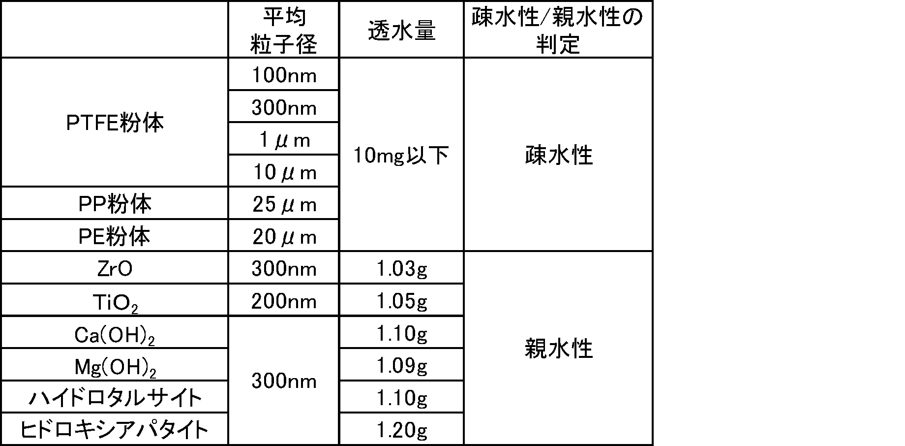
上記実施例の結果から、正極、負極、及び、セパレータを含んで構成される電気化学素子において、該セパレータが疎水性粒子及び親水性粒子をそれぞれ一定割合以上含み、かつ結着成分の含有量が一定割合未満のものであることにより、イオン伝導性を充分なものとしながら、耐久性に優れ、特に電気化学素子が充放電に伴って形態変化が起こる電極を含む場合にデンドライトによる電極間の短絡を充分に抑制でき、その結果、電気化学素子を長寿命化できることが分かった。中でも、親水性粒子として水酸化マグネシウムを用いた実施例1のセパレータは、耐久性に際立って優れることが分かった。
1、31:疎水性粒子(PTFE)
2、12:親水性粒子(Mg(OH)2)
3、13:結着成分(SBR)
4、14:空隙
5:試料粉体
6:円筒形容器
7:ろ紙
8:親水処理済ポリプロピレン製不織布
9:水
21:圧延によって繊維化されたPTFE
22:圧延によって緻密化されたMgO粒子
32:親水性粒子(MgO)
2、12:親水性粒子(Mg(OH)2)
3、13:結着成分(SBR)
4、14:空隙
5:試料粉体
6:円筒形容器
7:ろ紙
8:親水処理済ポリプロピレン製不織布
9:水
21:圧延によって繊維化されたPTFE
22:圧延によって緻密化されたMgO粒子
32:親水性粒子(MgO)
Claims (2)
- 電気化学素子に用いられるセパレータであって、
該セパレータは、疎水性粒子、親水性粒子、及び、所望により結着成分を含み、
疎水性粒子/(親水性粒子及び結着成分)の体積割合は、20/80を超え、
親水性粒子/(疎水性粒子及び結着成分)の体積割合は、20/80を超え、
結着成分/(疎水性粒子及び親水性粒子)の体積割合は、30/70未満である
ことを特徴とする電気化学素子用セパレータ。 - 請求項1に記載の電気化学素子用セパレータを含んで構成されることを特徴とする電気化学素子。
Priority Applications (1)
| Application Number | Priority Date | Filing Date | Title |
|---|---|---|---|
| JP2020557717A JP7161547B2 (ja) | 2018-11-26 | 2019-11-26 | 電気化学素子用セパレータ |
Applications Claiming Priority (2)
| Application Number | Priority Date | Filing Date | Title |
|---|---|---|---|
| JP2018220250 | 2018-11-26 | ||
| JP2018-220250 | 2018-11-26 |
Publications (1)
| Publication Number | Publication Date |
|---|---|
| WO2020111027A1 true WO2020111027A1 (ja) | 2020-06-04 |
Family
ID=70852828
Family Applications (1)
| Application Number | Title | Priority Date | Filing Date |
|---|---|---|---|
| PCT/JP2019/046067 Ceased WO2020111027A1 (ja) | 2018-11-26 | 2019-11-26 | 電気化学素子用セパレータ |
Country Status (2)
| Country | Link |
|---|---|
| JP (1) | JP7161547B2 (ja) |
| WO (1) | WO2020111027A1 (ja) |
Cited By (2)
| Publication number | Priority date | Publication date | Assignee | Title |
|---|---|---|---|---|
| KR20230161882A (ko) * | 2022-05-19 | 2023-11-28 | 도요타 지도샤(주) | 아연 이차 전지 |
| KR20250149230A (ko) * | 2024-04-08 | 2025-10-16 | 한국에너지기술연구원 | 아연 이차전지용 비다공성 분리막 및 그 제조방법 |
Citations (7)
| Publication number | Priority date | Publication date | Assignee | Title |
|---|---|---|---|---|
| JP2009064566A (ja) * | 2007-09-04 | 2009-03-26 | Hitachi Maxell Ltd | 電池用セパレータおよび非水電解質電池 |
| JP2011228188A (ja) * | 2010-04-22 | 2011-11-10 | Hitachi Maxell Energy Ltd | 電気化学素子用セパレータ、電気化学素子およびその製造方法 |
| JP2012048932A (ja) * | 2010-08-26 | 2012-03-08 | Hitachi Ltd | リチウムイオン二次電池 |
| JP2016510267A (ja) * | 2012-12-28 | 2016-04-07 | エスケー イノベーション カンパニー リミテッドSk Innovation Co.,Ltd. | 電気化学的安定性に優れた複合微多孔膜及びその製造方法 |
| JP2017152207A (ja) * | 2016-02-24 | 2017-08-31 | 三星エスディアイ株式会社Samsung SDI Co., Ltd. | 非水電解質二次電池用セパレータ(separator)、非水電解質二次電池、及び非水電解質二次電池の製造方法 |
| JP2017162699A (ja) * | 2016-03-10 | 2017-09-14 | 三星エスディアイ株式会社Samsung SDI Co., Ltd. | 巻回型二次電池用セパレータ(separator)、巻回型二次電池用セパレータの製造方法、扁平状巻回素子、巻回型二次電池、及び巻回型二次電池の製造方法 |
| JP2018147578A (ja) * | 2017-03-01 | 2018-09-20 | 旭化成株式会社 | 蓄電デバイス用セパレータ |
Family Cites Families (4)
| Publication number | Priority date | Publication date | Assignee | Title |
|---|---|---|---|---|
| WO2013073503A1 (ja) | 2011-11-15 | 2013-05-23 | 帝人株式会社 | 非水系二次電池用セパレータ及びその製造方法、並びに非水系二次電池 |
| WO2013125007A1 (ja) | 2012-02-23 | 2013-08-29 | 株式会社日立製作所 | 非水電解質二次電池用セパレータ、その製造方法および非水電解質二次電池 |
| US10074840B2 (en) | 2012-11-30 | 2018-09-11 | Teijin Limited | Separator for non-aqueous secondary battery and non-aqueous secondary battery |
| JP2017152268A (ja) | 2016-02-25 | 2017-08-31 | 東レバッテリーセパレータフィルム株式会社 | 電池用セパレータ |
-
2019
- 2019-11-26 JP JP2020557717A patent/JP7161547B2/ja active Active
- 2019-11-26 WO PCT/JP2019/046067 patent/WO2020111027A1/ja not_active Ceased
Patent Citations (7)
| Publication number | Priority date | Publication date | Assignee | Title |
|---|---|---|---|---|
| JP2009064566A (ja) * | 2007-09-04 | 2009-03-26 | Hitachi Maxell Ltd | 電池用セパレータおよび非水電解質電池 |
| JP2011228188A (ja) * | 2010-04-22 | 2011-11-10 | Hitachi Maxell Energy Ltd | 電気化学素子用セパレータ、電気化学素子およびその製造方法 |
| JP2012048932A (ja) * | 2010-08-26 | 2012-03-08 | Hitachi Ltd | リチウムイオン二次電池 |
| JP2016510267A (ja) * | 2012-12-28 | 2016-04-07 | エスケー イノベーション カンパニー リミテッドSk Innovation Co.,Ltd. | 電気化学的安定性に優れた複合微多孔膜及びその製造方法 |
| JP2017152207A (ja) * | 2016-02-24 | 2017-08-31 | 三星エスディアイ株式会社Samsung SDI Co., Ltd. | 非水電解質二次電池用セパレータ(separator)、非水電解質二次電池、及び非水電解質二次電池の製造方法 |
| JP2017162699A (ja) * | 2016-03-10 | 2017-09-14 | 三星エスディアイ株式会社Samsung SDI Co., Ltd. | 巻回型二次電池用セパレータ(separator)、巻回型二次電池用セパレータの製造方法、扁平状巻回素子、巻回型二次電池、及び巻回型二次電池の製造方法 |
| JP2018147578A (ja) * | 2017-03-01 | 2018-09-20 | 旭化成株式会社 | 蓄電デバイス用セパレータ |
Cited By (6)
| Publication number | Priority date | Publication date | Assignee | Title |
|---|---|---|---|---|
| KR20230161882A (ko) * | 2022-05-19 | 2023-11-28 | 도요타 지도샤(주) | 아연 이차 전지 |
| JP2023170509A (ja) * | 2022-05-19 | 2023-12-01 | トヨタ自動車株式会社 | 亜鉛二次電池 |
| JP7687275B2 (ja) | 2022-05-19 | 2025-06-03 | トヨタ自動車株式会社 | 亜鉛二次電池 |
| KR102888039B1 (ko) | 2022-05-19 | 2025-11-18 | 도요타 지도샤(주) | 아연 이차 전지 |
| KR20250149230A (ko) * | 2024-04-08 | 2025-10-16 | 한국에너지기술연구원 | 아연 이차전지용 비다공성 분리막 및 그 제조방법 |
| KR102903555B1 (ko) * | 2024-04-08 | 2025-12-26 | 한국에너지기술연구원 | 아연 이차전지용 비다공성 분리막 및 그 제조방법 |
Also Published As
| Publication number | Publication date |
|---|---|
| JP7161547B2 (ja) | 2022-10-26 |
| JPWO2020111027A1 (ja) | 2021-09-27 |
Similar Documents
| Publication | Publication Date | Title |
|---|---|---|
| JP6532186B2 (ja) | 電極前駆体、電極、及び、二次電池 | |
| KR102256769B1 (ko) | 전극 전구체, 전극 및 전지 | |
| JP6856823B2 (ja) | 負極及び亜鉛二次電池 | |
| JP6244174B2 (ja) | アニオン伝導膜及び電池 | |
| EP2750225A1 (en) | Negative electrode mixture or gel electrolyte, and battery using said negative electrode mixture or said gel electrolyte | |
| JP7007123B2 (ja) | 亜鉛二次電池用負極及び亜鉛二次電池 | |
| JP2015015229A (ja) | アニオン伝導性材料及び電池 | |
| JP6397646B2 (ja) | 亜鉛電極用合剤 | |
| JP6999283B2 (ja) | 電池 | |
| JP6306914B2 (ja) | 電極及び電池 | |
| JP2018147738A (ja) | 亜鉛負極二次電池用セパレータの製造方法及び亜鉛負極二次電池用セパレータ | |
| JP6716298B2 (ja) | 金属空気電池 | |
| JP7161547B2 (ja) | 電気化学素子用セパレータ | |
| JP6616565B2 (ja) | アニオン伝導性材料 | |
| JP2016186895A (ja) | アニオン伝導性膜、電極及び電池 | |
| CN106356589A (zh) | 金属空气电池用电解液和金属空气电池 | |
| JP6454496B2 (ja) | 電極及びそれを用いて構成される電池 | |
| JP7297382B2 (ja) | 電気化学キャパシタ | |
| JP2023055467A (ja) | 蓄電池用正極及びビスマス亜鉛蓄電池 | |
| JP6716308B2 (ja) | 金属空気電池 | |
| JP6625912B2 (ja) | 金属空気電池 | |
| JP7297383B2 (ja) | 電気化学キャパシタ | |
| JP2016152082A (ja) | アニオン伝導性膜及びその製造方法 | |
| JP2024121344A (ja) | 電池構成部材及び電池 | |
| US20250357498A1 (en) | Air electrode/separator conjugate and metal-air rechargeable battery |
Legal Events
| Date | Code | Title | Description |
|---|---|---|---|
| 121 | Ep: the epo has been informed by wipo that ep was designated in this application |
Ref document number: 19891118 Country of ref document: EP Kind code of ref document: A1 |
|
| ENP | Entry into the national phase |
Ref document number: 2020557717 Country of ref document: JP Kind code of ref document: A |
|
| NENP | Non-entry into the national phase |
Ref country code: DE |
|
| 122 | Ep: pct application non-entry in european phase |
Ref document number: 19891118 Country of ref document: EP Kind code of ref document: A1 |