WO2020110216A1 - 空気調和装置 - Google Patents
空気調和装置 Download PDFInfo
- Publication number
- WO2020110216A1 WO2020110216A1 PCT/JP2018/043715 JP2018043715W WO2020110216A1 WO 2020110216 A1 WO2020110216 A1 WO 2020110216A1 JP 2018043715 W JP2018043715 W JP 2018043715W WO 2020110216 A1 WO2020110216 A1 WO 2020110216A1
- Authority
- WO
- WIPO (PCT)
- Prior art keywords
- refrigerant
- unit
- leakage
- indoor
- notification
- Prior art date
Links
Images


Classifications
-
- F—MECHANICAL ENGINEERING; LIGHTING; HEATING; WEAPONS; BLASTING
- F25—REFRIGERATION OR COOLING; COMBINED HEATING AND REFRIGERATION SYSTEMS; HEAT PUMP SYSTEMS; MANUFACTURE OR STORAGE OF ICE; LIQUEFACTION SOLIDIFICATION OF GASES
- F25B—REFRIGERATION MACHINES, PLANTS OR SYSTEMS; COMBINED HEATING AND REFRIGERATION SYSTEMS; HEAT PUMP SYSTEMS
- F25B49/00—Arrangement or mounting of control or safety devices
- F25B49/02—Arrangement or mounting of control or safety devices for compression type machines, plants or systems
-
- F—MECHANICAL ENGINEERING; LIGHTING; HEATING; WEAPONS; BLASTING
- F24—HEATING; RANGES; VENTILATING
- F24F—AIR-CONDITIONING; AIR-HUMIDIFICATION; VENTILATION; USE OF AIR CURRENTS FOR SCREENING
- F24F11/00—Control or safety arrangements
- F24F11/30—Control or safety arrangements for purposes related to the operation of the system, e.g. for safety or monitoring
- F24F11/32—Responding to malfunctions or emergencies
- F24F11/36—Responding to malfunctions or emergencies to leakage of heat-exchange fluid
-
- F—MECHANICAL ENGINEERING; LIGHTING; HEATING; WEAPONS; BLASTING
- F24—HEATING; RANGES; VENTILATING
- F24F—AIR-CONDITIONING; AIR-HUMIDIFICATION; VENTILATION; USE OF AIR CURRENTS FOR SCREENING
- F24F11/00—Control or safety arrangements
- F24F11/50—Control or safety arrangements characterised by user interfaces or communication
- F24F11/52—Indication arrangements, e.g. displays
- F24F11/526—Indication arrangements, e.g. displays giving audible indications
-
- F—MECHANICAL ENGINEERING; LIGHTING; HEATING; WEAPONS; BLASTING
- F24—HEATING; RANGES; VENTILATING
- F24F—AIR-CONDITIONING; AIR-HUMIDIFICATION; VENTILATION; USE OF AIR CURRENTS FOR SCREENING
- F24F11/00—Control or safety arrangements
- F24F11/89—Arrangement or mounting of control or safety devices
-
- F—MECHANICAL ENGINEERING; LIGHTING; HEATING; WEAPONS; BLASTING
- F25—REFRIGERATION OR COOLING; COMBINED HEATING AND REFRIGERATION SYSTEMS; HEAT PUMP SYSTEMS; MANUFACTURE OR STORAGE OF ICE; LIQUEFACTION SOLIDIFICATION OF GASES
- F25B—REFRIGERATION MACHINES, PLANTS OR SYSTEMS; COMBINED HEATING AND REFRIGERATION SYSTEMS; HEAT PUMP SYSTEMS
- F25B2313/00—Compression machines, plants or systems with reversible cycle not otherwise provided for
- F25B2313/031—Sensor arrangements
- F25B2313/0314—Temperature sensors near the indoor heat exchanger
-
- F—MECHANICAL ENGINEERING; LIGHTING; HEATING; WEAPONS; BLASTING
- F25—REFRIGERATION OR COOLING; COMBINED HEATING AND REFRIGERATION SYSTEMS; HEAT PUMP SYSTEMS; MANUFACTURE OR STORAGE OF ICE; LIQUEFACTION SOLIDIFICATION OF GASES
- F25B—REFRIGERATION MACHINES, PLANTS OR SYSTEMS; COMBINED HEATING AND REFRIGERATION SYSTEMS; HEAT PUMP SYSTEMS
- F25B2500/00—Problems to be solved
- F25B2500/22—Preventing, detecting or repairing leaks of refrigeration fluids
- F25B2500/222—Detecting refrigerant leaks
-
- F—MECHANICAL ENGINEERING; LIGHTING; HEATING; WEAPONS; BLASTING
- F25—REFRIGERATION OR COOLING; COMBINED HEATING AND REFRIGERATION SYSTEMS; HEAT PUMP SYSTEMS; MANUFACTURE OR STORAGE OF ICE; LIQUEFACTION SOLIDIFICATION OF GASES
- F25B—REFRIGERATION MACHINES, PLANTS OR SYSTEMS; COMBINED HEATING AND REFRIGERATION SYSTEMS; HEAT PUMP SYSTEMS
- F25B2600/00—Control issues
- F25B2600/25—Control of valves
- F25B2600/2513—Expansion valves
Definitions
- the present invention relates to an air conditioner in which an indoor unit and an outdoor unit are connected via a refrigerant pipe through which a refrigerant flows.
- the HFC32 is slightly flammable.
- other refrigerants having a low global warming potential are often flammable, apart from the degree of flammability.
- replacement of propane, CO 2 , or the like, which has a smaller environmental load is under consideration in the future, and further consideration for safety is required.
- a lamp provided on a decorative panel of an indoor unit is turned on, or a speaker provided in the indoor unit outputs a sound or a buzzer. It is common to notify by sounding.
- a display for informing the leakage of the refrigerant on a display portion of a remote controller for operating the indoor unit provided in the room in which the indoor unit is installed is also known.
- the present invention is to solve the above-mentioned problem, by notifying the warning about the leakage of the refrigerant not only in the vicinity of the indoor unit but also in the external terminal device, the user who is not near the indoor unit Moreover, it is an object of the present invention to provide an air conditioner that can increase the degree of caution with respect to the notification and make it easier to notice, and can sufficiently inform the leakage of the refrigerant.
- An air conditioner is an air conditioner in which an indoor unit and an outdoor unit are connected via a refrigerant pipe through which a refrigerant flows, and a refrigerant detection unit that detects leakage of the refrigerant in the indoor unit.
- a notification unit for notifying that the refrigerant has leaked a communication unit capable of communicating with an external terminal device via a network, and a control unit controlling at least the notification unit and the communication unit.
- the notification unit includes, in addition to a display unit of a remote controller for operating the indoor unit, at least one of a display unit and a speaker provided on a housing surface of the indoor unit, and the external terminal.
- a device is included, and the control unit controls the notification unit and the communication unit to notify that the leakage of the refrigerant has occurred when the leakage of the refrigerant is detected by the refrigerant detection unit. Is.
- the warning about the leakage of the refrigerant is notified not only in the notification unit provided in the indoor unit but also in the external terminal device, so that the user who is not near the indoor unit can be notified of the warning. It is possible to increase the degree of caution with respect to the notification and make it easier to notice, and to sufficiently inform the leakage of the refrigerant.
- FIG. 1 is a configuration diagram showing an air conditioner according to Embodiment 1 of the present invention.
- FIG. 2 is a conceptual diagram showing an installation state of the air conditioner according to Embodiment 1 of the present invention.
- a plurality of indoor units 2a, 2b and an outdoor unit 3 are connected via refrigerant pipes 4a, 4b through which a refrigerant flows.
- the indoor units 2a and 2b are provided singly or plurally with respect to the outdoor unit 3, in the case of the first embodiment, two units are provided to construct the multi-type air conditioner 1.
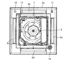
- the indoor units 2a and 2b are installed on the ceiling surface R of the room E, which is the space to be air-conditioned, and the decorative panel 5 is attached to the front surface side of the housing having a rectangular plane. That is, the indoor units 2a and 2b are installed on the ceiling surface R of one room E with the decorative panel 5 exposed.
- the decorative panel 5 is configured as a four-direction blow-out type capable of blowing the conditioned air in four directions.
- the indoor units 2a and 2b may be installed in the same room E or may be installed in a plurality of different rooms. Moreover, the indoor unit 2a, 2b is installed singularly or plurally in each room. Further, the decorative panel 5 is not limited to the four-direction blowing type, but may be the two-direction blowing type, and various other modes can be widely applied.
- a suction port 6 for sucking indoor air is provided in the center of the indoor units 2a, 2b.
- a blower 7 including, for example, a fan is provided on the back side of the suction port 6. Further, around the suction port 6, there are provided four outlets for blowing the heat-exchanged conditioned air in four directions. Then, louvers 8a to 8d for controlling the blowing direction of the conditioned air to be blown out are respectively provided at the four outlets.
- the indoor units 2a and 2b are provided with a refrigerant sensor 9 as a refrigerant detection unit for detecting refrigerant leakage.
- the refrigerant sensor 9 detects the presence of a refrigerant gas such as HFC32 or LP gas that may be used as a refrigerant for environmental protection in the future, and the concentration of the gas as the detection result is used as a sensor output (ppm). It is a gas sensor that emits.
- a semiconductor gas sensor that detects gas leakage due to desorption of oxygen atoms in the detection unit when the reducing gas touches the detection unit and the electrical resistance of the detection unit decreases can be applied.
- the display unit 10 and the speaker 11 which are the notification units for notifying that the leakage of the refrigerant has occurred. It is provided.
- the display unit 10 is composed of an LED (light emitting diode), but is not limited to this.
- the display unit 10 and the speaker 11 are provided adjacent to each other on the decorative panel 5. Accordingly, when the notification about the leakage of the refrigerant is made, the notification is made in the state where the light emission on the display unit 10 and the sound on the speaker 11 are adjacent to each other, so that the degree of caution to the user can be increased. Further, since the display unit 10 and the speaker 11 are provided adjacent to each other, it is possible to easily replace parts during maintenance and improve serviceability.
- the indoor units 2a and 2b are wired remote controllers capable of operating the "ON” or “OFF” operation of the indoor unit, the temperature, the air volume, the air direction, the timer, and other detailed settings. 12 is provided in a state of being connected to the control unit 13 via the wiring 14. The remote controller 12 is also connected to the outdoor unit 3 via the wiring 14.
- the remote controller 12 is provided with a communication unit 15 capable of communicating with an external terminal device 20 via a network.
- a short-range wireless communication such as a wireless LAN (Local Area Network) or Bluetooth (registered trademark), or communication such as the Internet or a mobile phone network is used. Widely applicable to the net.
- the control unit 13 controls at least one of the display unit 10 and the speaker 11 so as to notify that the leakage of the refrigerant has occurred, and controls the external terminal device 20. Is also controlled via the communication unit 15 to make the notification.
- the external terminal device 20 various terminals can be applied as long as they can notify the sound, light or display of a personal computer, a smartphone, a mobile phone, a tablet terminal or the like.
- the display unit 10, the speaker 11, and the external terminal device 20 as the notification unit inform that the leakage of the refrigerant has occurred.
- the display unit 10, the speaker 11, the external terminal device 20, and the control unit 13 are connected by wire or wirelessly.
- the control unit 13 controls the above-mentioned notification.
- a warning sound such as a buzzer is emitted, or a sound indicating that the refrigerant is leaking is announced to notify the user that the refrigerant is leaking.
- a warning light or the like may be turned on or blinked, and the user may be notified by light emission that the refrigerant is leaking.
- characters indicating that the refrigerant is leaking may be displayed on the display unit 10 to notify the user that the refrigerant is leaking by the characters.
- sound, light, and display may be combined to notify the user of refrigerant leakage.
- the sound, light, and display may be combined to notify the user of the refrigerant leakage.
- the indoor unit 2a (2b) in which the refrigerant has leaked may be notified in a manner different from that of the other indoor units 2b (2a). Examples of the mode at this time include changing the lighting color of the display unit 10, changing the wording to be displayed, changing the buzzer sound on the speaker 11, or changing the wording announced on the speaker 11. Be done.
- the decorative panel 5 of the indoor units 2a and 2b is provided with a light receiving unit 17 that receives an operation signal transmitted from a wireless remote controller 16 that can operate simple air conditioning settings such as temperature, air volume, and air direction.
- a wireless remote controller 16 that can operate simple air conditioning settings such as temperature, air volume, and air direction.
- the decorative panel 5 of each of the indoor units 2a and 2b is provided with a human sensor 18 as a temperature sensor that detects a person existing in the surroundings.
- the communication unit 15 is not limited to the remote controller 12, and may be provided on the remote controller 16 or both remote controllers 12 and 16 or the decorative panel 5.
- the light receiving unit 17 and the human sensor 18 are installed at positions facing each other on the decorative panel 5.
- the light receiving unit 17 is provided adjacent to the display unit 10 and the speaker 11 in the decorative panel 5.
- the light receiving unit 17 is provided adjacent to the display unit 10 and the speaker 11, so that it is possible to easily replace parts during maintenance and improve serviceability. Further, by disposing the display unit 10 and the speaker 11 away from the human sensor 18, it is possible to prevent the temperature deviation in the detection of the human sensor 18 due to the heat generated by the display unit 10 and the speaker 11.
- a shutoff valve 19 for shutting off the flow of the refrigerant between the indoor units 2a, 2b and the outdoor unit 3 is provided in the refrigerant pipes 4a, 4b that connect the indoor units 2a, 2b and the outdoor unit 3. ing.
- the shutoff valve 19 is switched from the open state to the closed state by the control unit 13 to isolate the indoor units 2a and 2b in which the refrigerant has leaked. It is possible.
- the blowers 7 of the indoor units 2a and 2b are forcibly operated.
- the forced operation means that the blowers 7 of the indoor units 2a and 2b are operated in a strong wind state even when the blowers 7 are stopped or in operation.
- the refrigerant leak is detected by the refrigerant sensor 9, the forced operation of the blower 7 of the indoor units 2a and 2b and the isolation of the indoor units 2a and 2b where the leakage of the refrigerant occurs by the shutoff valve 19 are used together. As a result, the expansion of refrigerant leakage can be avoided.
- FIG. 3 is a schematic diagram showing a refrigerant circuit of the air-conditioning apparatus 1 according to Embodiment 1 of the present invention.
- the air-conditioning apparatus 1 heats or cools the inside of the room to perform air-conditioning by moving heat between the outside air and the air in the room via a refrigerant.
- the air conditioner 1 has an outdoor unit 3 and indoor units 2a and 2b. Since the indoor units 2a and 2b have the same configuration, only one of the indoor units 2a and 2b will be illustrated and described here for convenience.
- the outdoor unit 3 and the indoor units 2a and 2b are connected by refrigerant pipes 4a and 4b, and a refrigerant circuit 30 in which a refrigerant circulates is configured.
- the compressor 31, the flow path switching device 32, the outdoor heat exchanger 33, the expansion valve 34, and the indoor heat exchanger 35 are connected via the refrigerant pipes 4a and 4b. ..
- the outdoor unit 3 has a compressor 31, a flow path switching device 32, an outdoor heat exchanger 33, and an expansion valve 34.
- the compressor 31 compresses the drawn refrigerant and discharges it.
- the compressor 31 may include an inverter device, and the inverter device may be configured to change the operating frequency to change the capacity of the compressor 31.
- the capacity of the compressor 31 is the amount of refrigerant sent out per unit time.
- the flow path switching device 32 is, for example, a four-way valve, and is a device that switches the direction of the refrigerant flow path.
- the air conditioner 1 can realize heating operation or cooling operation by switching the flow of the refrigerant using the flow path switching device 32 based on an instruction from the control unit 13 (FIG. 1).
- the outdoor heat exchanger 33 exchanges heat between the refrigerant and the outdoor air.
- the outdoor heat exchanger 33 functions as an evaporator during the heating operation, and performs heat exchange between the low-pressure refrigerant flowing from the refrigerant pipe 4b and the outdoor air to evaporate and vaporize the refrigerant, and the refrigerant pipe 4a side. Drain to.
- the outdoor heat exchanger 33 functions as a condenser, and performs heat exchange between the refrigerant that has been compressed by the compressor 31 that has flowed in from the flow path switching device 32 side and the outdoor air, so that the refrigerant is discharged. Condensate and liquefy.
- the outdoor heat exchanger 33 is provided with an outdoor blower 36 in order to increase the efficiency of heat exchange between the refrigerant and the outdoor air.
- the outdoor blower 36 may be equipped with an inverter device and change the operating frequency of the fan motor to change the rotation speed of the fan.
- the expansion valve 34 is a throttle device (flow rate control means), functions as an expansion valve by adjusting the flow rate of the refrigerant flowing through the expansion valve 34, and changes the opening to adjust the pressure of the refrigerant.
- the expansion valve 34 is composed of an electronic expansion valve or the like, the opening degree is adjusted based on an instruction from the control unit 13 (FIG. 1) or the like.
- the indoor units 2a and 2b have an indoor heat exchanger 35 that exchanges heat between the refrigerant and the indoor air, and a blower 7 that adjusts the flow of air for the indoor heat exchanger 35 to exchange heat.
- the indoor units 2a and 2b have a refrigerant sensor 9 that detects that the refrigerant used in the refrigerant circuit 30 has leaked.
- the indoor heat exchanger 35 functions as a condenser during the heating operation, performs heat exchange between the refrigerant flowing from the refrigerant pipe 4a and the indoor air, condenses and liquefies the refrigerant, and the refrigerant pipe 4b is provided. Drain.
- the indoor heat exchanger 35 functions as an evaporator during the cooling operation, performs heat exchange between the refrigerant that has been brought to a low pressure state by the expansion valve 34 and the indoor air, and causes the refrigerant to deprive the heat of the air to evaporate. To vaporize and flow out to the refrigerant pipe 4a side.
- the operating speed of the blower 7 is determined by the user setting.
- An inverter device may be attached to the blower 7 to change the operating frequency of the fan motor to change the rotation speed of the fan.
- the high-temperature and high-pressure gas refrigerant compressed and discharged by the compressor 31 flows into the outdoor heat exchanger 33 via the flow path switching device 32.
- the gas refrigerant flowing into the outdoor heat exchanger 33 is condensed by heat exchange with the outside air blown by the outdoor blower 36, becomes a low temperature refrigerant, and flows out from the outdoor heat exchanger 33.
- the refrigerant flowing out of the outdoor heat exchanger 33 is expanded and decompressed by the expansion valve 34 to become a low temperature low pressure gas-liquid two-phase refrigerant.
- the gas-liquid two-phase refrigerant flows into the indoor heat exchangers 35 of the indoor units 2a and 2b, evaporates by heat exchange with the indoor air blown by the blower 7, and becomes a low-temperature low-pressure gas refrigerant, which is the indoor heat exchange. It flows out of the container 35. At this time, the indoor air that is absorbed by the refrigerant and cooled becomes conditioned air (blowing air) and is blown out from the indoor units 2a and 2b into the room E (FIG. 2) that is the air conditioning target space.
- the gas refrigerant flowing out from the indoor heat exchanger 35 is sucked into the compressor 31 via the flow path switching device 32 and is compressed again. The above operation is repeated in the cooling operation of the air conditioner 1.
- the heating operation will be described as an operation example of the air conditioner 1.
- the high-temperature and high-pressure gas refrigerant compressed and discharged by the compressor 31 flows into the indoor heat exchanger 35 of the indoor units 2a and 2b via the flow path switching device 32.
- the gas refrigerant flowing into the indoor heat exchanger 35 is condensed by heat exchange with the indoor air blown by the blower 7, becomes a low-temperature refrigerant, and flows out from the indoor heat exchanger 35.
- the indoor air warmed by receiving heat from the gas refrigerant becomes conditioned air (blowing air) and is blown from the indoor units 2a and 2b into the room E (FIG. 2).
- the refrigerant flowing out from the indoor heat exchanger 35 is expanded and decompressed by the expansion valve 34 to become a low temperature low pressure gas-liquid two-phase refrigerant.
- the gas-liquid two-phase refrigerant flows into the outdoor heat exchanger 33 of the outdoor unit 3 and evaporates by heat exchange with the outside air blown by the outdoor blower 36 to become a low-temperature and low-pressure gas refrigerant and the outdoor heat exchanger 33. Drained from.
- the gas refrigerant flowing out of the outdoor heat exchanger 33 is sucked into the compressor 31 via the flow path switching device 32 and is compressed again. The above operation is repeated in the heating operation of the air conditioner 1.
- the control unit 13 displays to notify that the leakage of the refrigerant has occurred. It controls the unit 10 and the speaker 11. At the same time, the control unit 13 controls the external terminal device 20 via the communication unit 15 so as to notify that the refrigerant has leaked.
- the warning regarding the leakage of the refrigerant is issued not only to the display unit 10 and the speaker 11 provided on the decorative panel 5 of the indoor units 2a and 2b but also to the external terminal device 20. Can also be notified. Therefore, even a user who is not near the indoor units 2a and 2b can be made more aware of the notification and easily noticed, and the leakage of the refrigerant can be sufficiently known.
- control unit 13 causes the indoor unit 2a (2b) in which the refrigerant leak is detected by the refrigerant sensor 9 and the other indoor unit 2b (2a) to make different notifications that the refrigerant leak has occurred. It is preferable to control the display unit 10 and the speaker 11. Thus, the indoor unit 2a (2b) in which the refrigerant is leaking can be distinguished from the other indoor units 2b (2a) and notified, and can be easily identified during maintenance.
- FIG. 4 is a plan view showing an indoor unit of an air conditioner according to another embodiment of the present invention.
- the makeup panel 5 the light receiving unit 17 and the human sensor 18 are arranged diagonally, and the display unit 10 and the speaker 11 are arranged adjacent to the human sensor 18. Accordingly, when the notification about the leakage of the refrigerant is made, the notification is made in the state where the light emission on the display unit 10 and the sound on the speaker 11 are adjacent to each other, so that the degree of caution to the user can be increased. Further, since the display unit 10, the speaker 11, and the human sensor 18 are provided adjacent to each other, it is possible to easily replace parts during maintenance and improve serviceability.
- FIG. 5 is a plan view showing an indoor unit of an air conditioner according to another embodiment of the present invention.
- the light receiving section 17 and the human sensor 18 are arranged on a diagonal line
- the display section 10 is arranged next to the human sensor 18, and the speaker 11 is arranged next to the light receiving section 17.
- the notification is made in a diffused state, so that the degree of caution to the user can be increased. ..
- the display unit 10 and the human sensor 18 are provided adjacent to each other, and the speaker 11 and the light receiving unit 17 are provided adjacent to each other, it is easy to replace parts during maintenance, and serviceability is improved. It is possible to improve.
- FIG. 6 is a plan view showing an indoor unit of an air conditioner according to another embodiment of the present invention.
- the light receiving unit 17 and the human sensor 18 are arranged on a diagonal line, and the display unit 10 and the speaker 11 are arranged on a diagonal line orthogonal to these. That is, in the decorative panel 5, the display unit 10, the speaker 11, the light receiving unit 17, and the human sensor 18 are all arranged in a separated state.
- the notification about the leakage of the refrigerant is made, since the light emission in the display unit 10 and the sound in the speaker 11 are diagonally separated from each other, the notification is made in a diffused state, so that the degree of caution to the user can be increased.
- FIG. 7 is a plan view showing an indoor unit of an air conditioner according to another embodiment of the present invention.
- the light receiving unit 17 and the motion sensor 18 are arranged on a diagonal line
- the display unit 10 is arranged adjacent to the light receiving unit 17, and the speaker 11 is arranged so as to detect the light receiving unit 17 and the motion sensor. It is arranged apart from the sensor 18. Accordingly, when the notification about the leakage of the refrigerant is made, the notification is made in a state where the light emission in the display unit 10 and the sound in the speaker 11 are separated and diffused, so that the degree of caution to the user can be increased.
- the display unit 10 and the light receiving unit 17 are provided adjacent to each other, it is possible to easily replace parts during maintenance and improve serviceability. Further, by disposing the display unit 10, the speaker 11, and the light receiving unit 17 apart from the human sensor 18, the heat generated by the display unit 10 and the speaker 11 causes a temperature shift in the detection of the human sensor 18 in advance. Can be prevented.
- FIG. 8 is a plan view showing an indoor unit of an air conditioner according to another embodiment of the present invention.
- the light receiving unit 17 and the motion sensor 18 are arranged on a diagonal line
- the speaker 11 is arranged adjacent to the light receiving unit 17, and the display unit 10 is arranged so that the light receiving unit 17 and the motion sensor 17 are detected. It is arranged apart from the sensor 18. Accordingly, when the notification about the leakage of the refrigerant is made, the notification is made in a state where the light emission in the display unit 10 and the sound in the speaker 11 are separated and diffused, so that the degree of caution to the user can be increased.
- the speaker 11 and the light receiving unit 17 are provided adjacent to each other, it is possible to easily replace parts during maintenance and improve serviceability. Further, by disposing the display unit 10, the speaker 11, and the light receiving unit 17 apart from the human sensor 18, the heat generated by the display unit 10 and the speaker 11 causes a temperature shift in the detection of the human sensor 18 in advance. Can be prevented.
- FIG. 9 is a plan view showing an indoor unit of an air conditioner according to another embodiment of the present invention.
- the light receiving unit 17 and the human detection sensor 18 are arranged on a diagonal line
- the speaker 11 is arranged adjacent to the human detection sensor 18, and the display unit 10 includes the light receiving unit 17 and the human.
- the sensor 18 is spaced apart from the sensor 18. Accordingly, when the notification about the leakage of the refrigerant is made, the notification is made in a state where the light emission in the display unit 10 and the sound in the speaker 11 are separated and diffused, so that the degree of caution to the user can be increased.
- the speaker 11 and the human sensor 18 are provided adjacent to each other, it is possible to easily replace parts during maintenance and improve serviceability.
- FIG. 10 is a plan view showing an indoor unit of an air conditioner according to another embodiment of the present invention.
- the light receiving unit 17 and the motion sensor 18 are arranged on a diagonal line
- the display unit 10 is arranged adjacent to the motion sensor 18, and the speaker 11 is arranged in the light receiving unit 17 and the human body.
- the sensor 18 is spaced apart from the sensor 18. Accordingly, when the notification about the leakage of the refrigerant is made, the notification is made in a state where the light emission in the display unit 10 and the sound in the speaker 11 are separated and diffused, so that the degree of caution to the user can be increased. Further, since the display unit 10 and the human sensor 18 are provided adjacent to each other, it is possible to easily replace parts during maintenance and improve serviceability.
- 1 air conditioner 2a indoor unit, 2b indoor unit, 3 outdoor unit, 4a, 4b refrigerant piping, 5 makeup panel, 6 suction port, 7 blower, 8a, 8b, 8c, 8d louver, 9 refrigerant sensor, 10 display unit , 11 speaker, 12 remote controller, 13 control unit, 14 wiring, 15 communication unit, 16 remote controller, 17 light receiving unit, 18 human sensor, 19 shutoff valve, 20 terminal device, 30 refrigerant circuit, 31 compressor, 32 flow path switching Device, 33 outdoor heat exchanger, 34 expansion valve, 35 indoor heat exchanger, 36 outdoor blower, E indoor room, R ceiling surface.
Landscapes
- Engineering & Computer Science (AREA)
- Mechanical Engineering (AREA)
- General Engineering & Computer Science (AREA)
- Chemical & Material Sciences (AREA)
- Combustion & Propulsion (AREA)
- Physics & Mathematics (AREA)
- Thermal Sciences (AREA)
- Human Computer Interaction (AREA)
- Air Conditioning Control Device (AREA)
Abstract
Description
また、室内機の近くにユーザーがいたとしても、そのユーザーが何らかの理由で冷媒の漏洩に関する報知に気付かなかった場合、同じ状態で報知を続けても当該冷媒の漏洩が周知される可能性が低く、冷媒の漏洩に関する報知態様としては不十分であった。
<空気調和装置1の構成>
図1は、本発明の実施の形態1に係る空気調和装置を示す構成図である。図2は、本発明の実施の形態1に係る空気調和装置の設置状態を示す概念図である。図1および図2に示すように、本実施の形態1に係る空気調和装置1は、複数の室内機2a、2bと室外機3とが冷媒を流通する冷媒配管4a、4bを介して接続されている。なお、室内機2a、2bは室外機3に対して単数または複数設けられるが、本実施の形態1の場合、2台設けられることでマルチ型の空気調和装置1を構築している。また、以下の説明において、室内機2a、2bは同一の構成からなるため、本実施の形態1では便宜上、図2を除き室内機2aのみを図示して説明することとする。さらに、冷媒配管4a、4bも同様に、図2では、冷媒配管4aのみを図示して説明することとする。
図3は、本発明の実施の形態1に係る空気調和装置1の冷媒回路を示す模式図である。図3に示すように、空気調和装置1は、冷媒を介して外気と室内の空気との間で熱を移動させることにより、室内を暖房または冷房して空気調和を行う。空気調和装置1は、室外機3と、室内機2a、2bとを有する。なお、室内機2a、2bは同一の構成からなるため、ここでは便宜上、室内機2a、2bの一方のみを図示して説明することとする。
次に、空気調和装置1の動作例として冷房運転の動作を説明する。圧縮機31によって圧縮され吐出された高温高圧のガス冷媒は、流路切替装置32を経由して、室外熱交換器33に流入する。室外熱交換器33に流入したガス冷媒は、室外送風機36により送風される外気との熱交換により凝縮し、低温の冷媒となって、室外熱交換器33から流出する。室外熱交換器33から流出した冷媒は、膨張弁34によって膨張および減圧され、低温低圧の気液二相冷媒となる。この気液二相冷媒は、室内機2a、2bの室内熱交換器35に流入し、送風機7により送風される室内空気との熱交換により蒸発し、低温低圧のガス冷媒となって室内熱交換器35から流出する。このとき、冷媒に吸熱されて冷却された室内空気は、空調空気(吹出風)となって、室内機2a、2bから空調対象空間である室内E(図2)に吹き出される。室内熱交換器35から流出したガス冷媒は、流路切替装置32を経由して圧縮機31に吸入され、再び圧縮される。空気調和装置1の冷房運転は、以上の動作が繰り返される。
以上、説明したように、本実施の形態1の空気調和装置1では、制御部13が、冷媒センサー9によって冷媒の漏洩が検知された場合、冷媒の漏洩が発生した旨を報知するように表示部10およびスピーカー11を制御する。これと共に、制御部13が、冷媒の漏洩が発生した旨を報知するように通信部15を介して外部の端末機器20を制御する。これにより、本実施の形態1の空気調和装置1では、冷媒の漏洩に関する警告を、室内機2a、2bの化粧パネル5に設けられた表示部10およびスピーカー11のみならず外部の端末機器20においても報知することができる。よって、室内機2a、2bの近くにいないユーザーにも当該報知に対する注意度を高めて気付かせ易くすることができ、冷媒の漏洩を十分に周知させることができる。
次に、図4~図10を参照しながら、本発明の他の実施の形態に係る室内機2a、2bの化粧パネル5について説明する。なお、ここでは、化粧パネル5における表示部10およびスピーカー11並びに受光部17および人感センサー18の配置についての説明であり、その他の構成については前述した実施の形態1と同様であるため、重複する説明は割愛するものとする。
Claims (7)
- 室内機と室外機とが冷媒を流通する冷媒配管を介して接続された空気調和装置であって、
前記室内機における前記冷媒の漏洩を検知する冷媒検知部と、
前記冷媒の漏洩が発生した旨を報知するための報知部と、
ネットワークを介して外部の端末機器と通信可能な通信部と、
少なくとも前記報知部および前記通信部を制御する制御部と、を備え、
前記報知部には、
前記室内機を操作するためのリモコンにおける表示部に加えて、前記室内機の筐体表面に設けられた表示部またはスピーカーのうちの少なくとも一つと、前記外部の端末機器とが含まれ、
前記制御部は、
前記冷媒検知部によって前記冷媒の漏洩が検知された場合、前記冷媒の漏洩が発生した旨を報知するように前記報知部および前記通信部を制御する空気調和装置。 - 前記表示部と前記スピーカーとの少なくとも一方が、前記筐体表面に設けられた温度センサーまたは前記リモコンからの操作信号を受信するための受光部の少なくとも一方と隣り合って設置されている請求項1に記載の空気調和装置。
- 前記表示部と前記スピーカーとの少なくとも一方が、前記筐体表面に設けられた温度センサーまたは前記リモコンからの操作信号を受信するための受光部の少なくとも一方と離間して設置されている請求項2に記載の空気調和装置。
- 前記通信部は、前記リモコンに設けられている請求項1~3のいずれか一項に記載の空気調和装置。
- 前記冷媒配管に設けられ、前記室内機と前記室外機との間における前記冷媒の流通を遮断するための遮断弁を更に備え、
前記制御部は、
前記冷媒検知部によって前記冷媒の漏洩が検知された場合、前記遮断弁を開状態から閉状態に切り替える請求項1~4のいずれか一項に記載の空気調和装置。 - 前記制御部は、
前記冷媒検知部によって前記冷媒の漏洩が検知された場合、前記室内機の送風機を強制運転させる請求項1~5のいずれか一項に記載の空気調和装置。 - 前記室内機が複数設けられ、
前記制御部は、
複数の前記室内機のうち、前記冷媒検知部によって前記冷媒の漏洩が検知された室内機と、その他の室内機とで、前記冷媒の漏洩が発生した旨の報知を異ならせるように前記報知部を制御する請求項1~6のいずれか一項に記載の空気調和装置。
Priority Applications (5)
| Application Number | Priority Date | Filing Date | Title |
|---|---|---|---|
| US17/273,418 US11959675B2 (en) | 2018-11-28 | 2018-11-28 | Air-conditioning apparatus |
| AU2018451457A AU2018451457B2 (en) | 2018-11-28 | 2018-11-28 | Air-conditioning apparatus |
| DE112018008171.0T DE112018008171T5 (de) | 2018-11-28 | 2018-11-28 | Klimaanlage |
| PCT/JP2018/043715 WO2020110216A1 (ja) | 2018-11-28 | 2018-11-28 | 空気調和装置 |
| JP2020557448A JPWO2020110216A1 (ja) | 2018-11-28 | 2018-11-28 | 空気調和装置 |
Applications Claiming Priority (1)
| Application Number | Priority Date | Filing Date | Title |
|---|---|---|---|
| PCT/JP2018/043715 WO2020110216A1 (ja) | 2018-11-28 | 2018-11-28 | 空気調和装置 |
Publications (1)
| Publication Number | Publication Date |
|---|---|
| WO2020110216A1 true WO2020110216A1 (ja) | 2020-06-04 |
Family
ID=70852360
Family Applications (1)
| Application Number | Title | Priority Date | Filing Date |
|---|---|---|---|
| PCT/JP2018/043715 WO2020110216A1 (ja) | 2018-11-28 | 2018-11-28 | 空気調和装置 |
Country Status (5)
| Country | Link |
|---|---|
| US (1) | US11959675B2 (ja) |
| JP (1) | JPWO2020110216A1 (ja) |
| AU (1) | AU2018451457B2 (ja) |
| DE (1) | DE112018008171T5 (ja) |
| WO (1) | WO2020110216A1 (ja) |
Families Citing this family (3)
| Publication number | Priority date | Publication date | Assignee | Title |
|---|---|---|---|---|
| KR102654833B1 (ko) * | 2019-08-14 | 2024-04-05 | 삼성전자주식회사 | 공기 조화기 및 그 제어 방법 |
| EP3862641A1 (en) * | 2020-02-05 | 2021-08-11 | Daikin Industries, Ltd. | Heat-pump system, indicator, usage-side unit, and information output method |
| US20220244686A1 (en) * | 2021-02-04 | 2022-08-04 | Abb Schweiz Ag | Virus control building management system |
Citations (3)
| Publication number | Priority date | Publication date | Assignee | Title |
|---|---|---|---|---|
| JP2016070568A (ja) * | 2014-09-29 | 2016-05-09 | 日立アプライアンス株式会社 | 空気調和機の室内機 |
| WO2016088167A1 (ja) * | 2014-12-01 | 2016-06-09 | 三菱電機株式会社 | 空気調和装置 |
| JP2017053509A (ja) * | 2015-09-08 | 2017-03-16 | ジョンソンコントロールズ ヒタチ エア コンディショニング テクノロジー(ホンコン)リミテッド | 空気調和システムおよび空気調和システムの警告報知方法 |
Family Cites Families (13)
| Publication number | Priority date | Publication date | Assignee | Title |
|---|---|---|---|---|
| US6978627B2 (en) | 2002-01-31 | 2005-12-27 | Mitsubishi Denki Kabushiki Kaisha | Air conditioner control system, central remote controller, and facility controller |
| JP4202378B2 (ja) * | 2002-01-31 | 2008-12-24 | 三菱電機株式会社 | 空気調和システム |
| JP2007139314A (ja) * | 2005-11-18 | 2007-06-07 | Matsushita Electric Ind Co Ltd | 空気調和機 |
| JP5020222B2 (ja) * | 2008-12-08 | 2012-09-05 | 三菱電機株式会社 | 空気調和機 |
| JP2012013348A (ja) * | 2010-07-02 | 2012-01-19 | Panasonic Corp | 空気調和機 |
| KR20140099747A (ko) * | 2013-02-04 | 2014-08-13 | 엘지전자 주식회사 | 공기 조화 시스템 및 그 제어 방법 |
| JP6285166B2 (ja) | 2013-12-11 | 2018-02-28 | 日立ジョンソンコントロールズ空調株式会社 | 空気調和機 |
| US10060645B2 (en) * | 2014-06-19 | 2018-08-28 | Mitsubishi Electric Corporation | Indoor unit of air-conditioning apparatus and air-conditioning apparatus including the indoor unit |
| JP6640473B2 (ja) | 2015-05-28 | 2020-02-05 | 日立ジョンソンコントロールズ空調株式会社 | 空気調和機、及び空気調和機の表示制御方法 |
| JP2017032251A (ja) | 2015-08-05 | 2017-02-09 | 株式会社富士通ゼネラル | マルチタイプ空気調和装置 |
| JP6701337B2 (ja) * | 2016-07-15 | 2020-05-27 | 三菱電機株式会社 | 空気調和装置 |
| JP6468300B2 (ja) * | 2017-02-13 | 2019-02-13 | 株式会社富士通ゼネラル | 空気調和装置 |
| WO2018154652A1 (ja) | 2017-02-22 | 2018-08-30 | 三菱電機株式会社 | リモコン装置、空調機及び空調システム |
-
2018
- 2018-11-28 JP JP2020557448A patent/JPWO2020110216A1/ja active Pending
- 2018-11-28 US US17/273,418 patent/US11959675B2/en active Active
- 2018-11-28 AU AU2018451457A patent/AU2018451457B2/en active Active
- 2018-11-28 DE DE112018008171.0T patent/DE112018008171T5/de active Pending
- 2018-11-28 WO PCT/JP2018/043715 patent/WO2020110216A1/ja active Application Filing
Patent Citations (3)
| Publication number | Priority date | Publication date | Assignee | Title |
|---|---|---|---|---|
| JP2016070568A (ja) * | 2014-09-29 | 2016-05-09 | 日立アプライアンス株式会社 | 空気調和機の室内機 |
| WO2016088167A1 (ja) * | 2014-12-01 | 2016-06-09 | 三菱電機株式会社 | 空気調和装置 |
| JP2017053509A (ja) * | 2015-09-08 | 2017-03-16 | ジョンソンコントロールズ ヒタチ エア コンディショニング テクノロジー(ホンコン)リミテッド | 空気調和システムおよび空気調和システムの警告報知方法 |
Also Published As
| Publication number | Publication date |
|---|---|
| AU2018451457B2 (en) | 2022-06-30 |
| DE112018008171T5 (de) | 2021-08-26 |
| US11959675B2 (en) | 2024-04-16 |
| JPWO2020110216A1 (ja) | 2021-09-02 |
| US20210199360A1 (en) | 2021-07-01 |
| AU2018451457A1 (en) | 2021-04-15 |
Similar Documents
| Publication | Publication Date | Title |
|---|---|---|
| WO2020105117A1 (ja) | 空気調和装置 | |
| CN108474604B (zh) | 空调装置 | |
| JP6168113B2 (ja) | 空調室内機 | |
| JP6250236B1 (ja) | 冷凍サイクル装置 | |
| WO2020110216A1 (ja) | 空気調和装置 | |
| JP2017048993A (ja) | 空調システム | |
| US11927355B2 (en) | Air conditioning and ventilating system | |
| JP6253853B1 (ja) | 冷凍サイクル装置 | |
| JP6498289B2 (ja) | 冷凍サイクルシステム | |
| US20230052745A1 (en) | Refrigerant cycle apparatus | |
| JPWO2020004108A1 (ja) | 空気調和システム | |
| JP7381944B2 (ja) | 空調システム | |
| JP2006234296A (ja) | マルチ型空気調和装置 | |
| CN109073256A (zh) | 空调装置 | |
| JP7421131B2 (ja) | 空調システム | |
| JP2007247924A (ja) | 空気調和装置 | |
| JP2017040381A (ja) | 空調室内機 | |
| JP6906708B2 (ja) | 水冷式空気調和装置 | |
| JP2021124245A (ja) | 空気調和システム | |
| WO2019198176A1 (ja) | 空気調和装置の室内機 | |
| JP2022081022A (ja) | 空気調和装置 | |
| WO2022230324A1 (ja) | 空調システム、その運転制御方法、及び空調システムの運転制御装置 | |
| JP2019143943A (ja) | 低能力室内機 | |
| WO2022153386A1 (ja) | 空気調和装置 | |
| JP2022170222A (ja) | 空気調和装置 |
Legal Events
| Date | Code | Title | Description |
|---|---|---|---|
| 121 | Ep: the epo has been informed by wipo that ep was designated in this application |
Ref document number: 18941780 Country of ref document: EP Kind code of ref document: A1 |
|
| ENP | Entry into the national phase |
Ref document number: 2020557448 Country of ref document: JP Kind code of ref document: A |
|
| ENP | Entry into the national phase |
Ref document number: 2018451457 Country of ref document: AU Date of ref document: 20181128 Kind code of ref document: A |
|
| 122 | Ep: pct application non-entry in european phase |
Ref document number: 18941780 Country of ref document: EP Kind code of ref document: A1 |