WO2020080098A1 - Dispositif de distribution de carburant - Google Patents
Dispositif de distribution de carburant Download PDFInfo
- Publication number
- WO2020080098A1 WO2020080098A1 PCT/JP2019/038762 JP2019038762W WO2020080098A1 WO 2020080098 A1 WO2020080098 A1 WO 2020080098A1 JP 2019038762 W JP2019038762 W JP 2019038762W WO 2020080098 A1 WO2020080098 A1 WO 2020080098A1
- Authority
- WO
- WIPO (PCT)
- Prior art keywords
- fuel
- passage
- pressurized
- supply device
- pressurized fuel
- Prior art date
- Legal status (The legal status is an assumption and is not a legal conclusion. Google has not performed a legal analysis and makes no representation as to the accuracy of the status listed.)
- Ceased
Links
Images

Classifications
-
- F—MECHANICAL ENGINEERING; LIGHTING; HEATING; WEAPONS; BLASTING
- F02—COMBUSTION ENGINES; HOT-GAS OR COMBUSTION-PRODUCT ENGINE PLANTS
- F02M—SUPPLYING COMBUSTION ENGINES IN GENERAL WITH COMBUSTIBLE MIXTURES OR CONSTITUENTS THEREOF
- F02M37/00—Apparatus or systems for feeding liquid fuel from storage containers to carburettors or fuel-injection apparatus; Arrangements for purifying liquid fuel specially adapted for, or arranged on, internal-combustion engines
- F02M37/0047—Layout or arrangement of systems for feeding fuel
- F02M37/0052—Details on the fuel return circuit; Arrangement of pressure regulators
-
- F—MECHANICAL ENGINEERING; LIGHTING; HEATING; WEAPONS; BLASTING
- F02—COMBUSTION ENGINES; HOT-GAS OR COMBUSTION-PRODUCT ENGINE PLANTS
- F02M—SUPPLYING COMBUSTION ENGINES IN GENERAL WITH COMBUSTIBLE MIXTURES OR CONSTITUENTS THEREOF
- F02M37/00—Apparatus or systems for feeding liquid fuel from storage containers to carburettors or fuel-injection apparatus; Arrangements for purifying liquid fuel specially adapted for, or arranged on, internal-combustion engines
- F02M37/04—Feeding by means of driven pumps
- F02M37/08—Feeding by means of driven pumps electrically driven
- F02M37/10—Feeding by means of driven pumps electrically driven submerged in fuel, e.g. in reservoir
- F02M37/106—Feeding by means of driven pumps electrically driven submerged in fuel, e.g. in reservoir the pump being installed in a sub-tank
-
- F—MECHANICAL ENGINEERING; LIGHTING; HEATING; WEAPONS; BLASTING
- F02—COMBUSTION ENGINES; HOT-GAS OR COMBUSTION-PRODUCT ENGINE PLANTS
- F02M—SUPPLYING COMBUSTION ENGINES IN GENERAL WITH COMBUSTIBLE MIXTURES OR CONSTITUENTS THEREOF
- F02M37/00—Apparatus or systems for feeding liquid fuel from storage containers to carburettors or fuel-injection apparatus; Arrangements for purifying liquid fuel specially adapted for, or arranged on, internal-combustion engines
- F02M37/22—Arrangements for purifying liquid fuel specially adapted for, or arranged on, internal-combustion engines, e.g. arrangements in the feeding system
- F02M37/32—Arrangements for purifying liquid fuel specially adapted for, or arranged on, internal-combustion engines, e.g. arrangements in the feeding system characterised by filters or filter arrangements
- F02M37/44—Filters structurally associated with pumps
-
- F—MECHANICAL ENGINEERING; LIGHTING; HEATING; WEAPONS; BLASTING
- F02—COMBUSTION ENGINES; HOT-GAS OR COMBUSTION-PRODUCT ENGINE PLANTS
- F02M—SUPPLYING COMBUSTION ENGINES IN GENERAL WITH COMBUSTIBLE MIXTURES OR CONSTITUENTS THEREOF
- F02M37/00—Apparatus or systems for feeding liquid fuel from storage containers to carburettors or fuel-injection apparatus; Arrangements for purifying liquid fuel specially adapted for, or arranged on, internal-combustion engines
- F02M37/04—Feeding by means of driven pumps
- F02M37/08—Feeding by means of driven pumps electrically driven
- F02M2037/082—Details of the entry of the current supply lines into the pump housing, e.g. wire connectors, grommets, plugs or sockets
-
- F—MECHANICAL ENGINEERING; LIGHTING; HEATING; WEAPONS; BLASTING
- F02—COMBUSTION ENGINES; HOT-GAS OR COMBUSTION-PRODUCT ENGINE PLANTS
- F02M—SUPPLYING COMBUSTION ENGINES IN GENERAL WITH COMBUSTIBLE MIXTURES OR CONSTITUENTS THEREOF
- F02M37/00—Apparatus or systems for feeding liquid fuel from storage containers to carburettors or fuel-injection apparatus; Arrangements for purifying liquid fuel specially adapted for, or arranged on, internal-combustion engines
- F02M37/04—Feeding by means of driven pumps
- F02M37/08—Feeding by means of driven pumps electrically driven
Definitions
- the present disclosure relates to a fuel supply device.
- WO2017 / 141628 discloses a conventional fuel supply device.
- This fuel supply device includes a fuel pump, a sub tank, a leak passage, and a fuel filter.
- the fuel pump sucks the fuel in the fuel tank, boosts the pressure, and then discharges the fuel.
- the sub tank stores fuel.
- the leak passage returns a part of the pressurized fuel discharged from the fuel pump into the sub tank.
- the fuel filter has a bag-shaped filter member that is provided at the bottom of the sub-tank and filters the fuel drawn into the fuel pump. Pressurized fuel is ejected from the leak passage toward the filter member.
- the fuel ejected from the leak passage toward the filter member may deform the filter member into a concave shape.
- the problem of the present disclosure is to suppress the deformation of the filter member of the fuel filter due to the pressurized fuel ejected from the pressurized fuel return passage.
- One means of the present disclosure is a fuel supply device for supplying the fuel in a fuel tank to an internal combustion engine, the fuel pump, a sub-tank for storing the fuel, and a part of the pressurized fuel discharged from the fuel pump. And a fuel filter having a bag-shaped filter member provided at the bottom of the sub-tank for filtering the fuel sucked into the fuel pump.
- the fuel supply device includes a wall member that diverts the flow of the pressurized fuel so that the pressurized fuel ejected from the pressurized fuel return passage does not collide with the filter member.
- the flow of the pressurized fuel ejected from the pressurized fuel return passage is diverted by the wall member, so that the direct collision of the pressurized fuel with the filter member of the fuel filter can be avoided. Accordingly, the deformation of the filter member of the fuel filter due to the pressurized fuel ejected from the pressurized fuel return passage can be suppressed.
- FIG. 5 is a front view showing the pump unit of FIG. 4 partially broken away.
- FIG. 5 is a perspective view which shows the left side part of the pump unit of FIG.
- FIG. 5 is a sectional side view which shows the fuel receiving cylinder part of the pump unit of FIG.
- FIG. drawing which shows the front-end
- the fuel supply device is installed in a fuel tank mounted on a vehicle such as an automobile equipped with an engine which is an internal combustion engine, and supplies the fuel in the fuel tank to the engine.
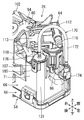
- 1 is a perspective view showing a fuel supply device
- FIG. 2 is a front view thereof
- FIG. 3 is a rear view thereof. 1 to 3, the front, rear, left, right, upper, and lower directions correspond to the respective directions of the vehicle. That is, the front-rear direction corresponds to the vehicle length direction, the left-right direction corresponds to the vehicle width direction, and the up-down direction corresponds to the vehicle height direction.
- the front-back direction and the left-right direction of the fuel supply device may be oriented in any directions.
- the fuel tank 10 is a hollow container having an upper wall portion 11 and a bottom wall portion 12. A circular hole-shaped opening 13 is formed in the upper wall 11.
- the upper wall portion 11 and the lower wall portion 12 are mounted on the vehicle with the upper wall portion 11 and the bottom wall portion 12 in a horizontal state.
- the fuel tank 10 is made of resin and deforms (mainly expands and contracts in the vertical direction) due to changes in tank internal pressure.
- gasoline as a liquid fuel is stored.
- the fuel supply device 20 includes a flange unit 22, a joint member 24, and a pump unit 26.
- a joint member 24 is connected to the flange unit 22 so as to be vertically movable.
- a pump unit 26 is connected to the joint member 24 so as to be vertically rotatable.
- the flange unit 22 includes a flange body 28.
- the flange main body 28 is mainly formed of a circular plate-shaped cover plate portion 32.
- the flange body 28 is made of resin.
- a short cylindrical fitting tube portion 33 is concentrically formed on the lower surface of the lid plate portion 32.
- An annular plate-shaped flange portion 34 is formed on the outer peripheral portion of the lid plate portion 32 so as to project radially outward from the fitting cylinder portion 33.
- the lid plate portion 32 is provided with a fuel discharge port 37, a first electric connector portion 38, and a second electric connector portion 39.
- the fuel discharge port 37 is formed in a straight tube shape that penetrates the lid plate portion 32 in the vertical direction. Further, a predetermined number of metal terminals are arranged in both electric connector parts 38, 39.
- a hollow container-shaped canister portion 150 is formed at the rear of the flange body 28.
- the outer shape of the canister portion 150 is formed in a substantially semi-cylindrical shape that is concentric with the flange body 28.
- An adsorbent e.g., activated carbon
- An evaporation port 151, an atmosphere port 152, and a purge port 153, which communicate with the inside of the canister portion 150, are formed on the upper surface of the flange body 28.
- a pair of left and right fixed side rails 155 that extend linearly in the vertical direction are formed symmetrically (see FIG. 2).
- the joint member 24 has a joint body 46, a spring guide 47, and a pair of left and right moving side rails 157.
- the joint body 46 is made of resin, and is formed in a vertically elongated strip plate shape that is flat in the front-rear direction and extends in the up-down direction.
- An engaging shaft hole 50 penetrating in the front-rear direction is formed in the lower portion of the joint body 46 (see FIG. 3).
- the spring guide 47 is formed in a pillar shape on the central portion of the joint body 46.
- Both moving-side rails 157 linearly extend in the up-and-down direction on both left and right sides of the upper portion of the joint member 24. Both moving side rails 157 are formed symmetrically on the joint body 46.
- the spring 52 which is a metal coil spring, is fitted into the spring guide 47 of the joint member 24.
- both moving side rails 157 of the joint member 24 are engaged with both fixed side rails 155 of the flange unit 22 so as to be vertically movable within a predetermined range. That is, the joint member 24 is connected to the flange unit 22 so as to be vertically movable. Further, the flange body 28 and the joint body 46 are urged in the separating direction by the elasticity of the spring 52.
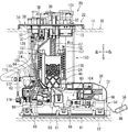
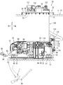
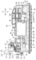
- the pump unit 26 includes a sub tank 54, a sender gauge 56, a fuel pump 58, a pump case 60, a pressure regulator 62, and a regulator case 64.
- FIG. 4 is a plan view showing the pump unit
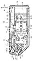
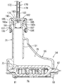
- FIG. 5 is a front view showing the same with a part thereof cut away
- FIG. 6 is a perspective view showing the left side.
- the sender gauge 56 is omitted in FIGS. 4 and 5.
- the sub tank 54 includes a sub tank main body 66, a fuel filter 67, and a cover member 68.
- the sub tank main body 66 is made of resin and is formed in an inverted shallow box shape having an opening on the lower surface.
- the sub tank main body 66 is formed in a rectangular shape that extends in the left-right direction in plan view (see FIG. 4).
- a square opening hole 70 is formed at a position on the right side of the upper surface of the sub tank body 66.
- a substantially rectangular tubular fuel receiving tubular portion 71 extending upward is formed (see FIG. 6). The upper surface of the fuel receiving cylinder portion 71 is open.
- FIG. 7 is a side sectional view showing the fuel receiving cylinder portion.
- a hollow cylindrical guide cylinder portion 131 extending in the vertical direction is formed in the fuel receiving cylinder portion 71.
- the guide cylinder portion 131 is arranged in the left side portion of the fuel receiving cylinder portion 71.
- the lower surface of the guide tube portion 131 is opened at a position higher than the lower surface of the sub tank body 66.
- the guide cylinder portion 131 is integrally formed by utilizing a corner formed by the left side portion and the rear side portion of the fuel receiving cylinder portion 71.
- an engaging shaft 72 projecting rearward is formed at a position on the lower left side of the rear surface of the sub tank main body 66 (see FIG. 4).
- a plate-shaped standing wall portion 73 facing the front-rear direction is formed on the right rear portion of the upper surface portion of the sub tank body 66 (see FIG. 1).
- the fuel filter 67 includes a filter member 75, an inner frame member 76, and a connecting pipe 77.
- the filter member 75 is a member that filters fuel, and is formed in a hollow bag shape with a filter material made of a resin non-woven fabric.
- the outer shape of the filter member 75 is formed in a rectangular shape that is flat in the up-down direction and has the left-right direction as the longitudinal direction.
- the inner frame member 76 is made of resin and has a skeletal structure that holds the filter member 75 in a state of being swelled in the vertical direction.
- the connecting pipe 77 is made of resin and formed in a vertical circular tube shape.
- the connecting pipe 77 is joined to the right portion of the inner frame member 76 by heat welding.
- the upper surface of the filter member 75 is sandwiched between the inner frame member 76 and the connecting pipe 77.
- the inside and outside of the filter member 75 are communicated with each other via the connection pipe 77.
- the filter member 75 is arranged with respect to the sub tank main body 66 so as to close the lower surface opening thereof.
- a fuel storage space 79 for storing fuel is formed between the sub tank body 66 and the filter member 75.
- the connection pipe 77 is arranged in the opening hole 70 of the sub tank body 66.
- An annular space portion between the opening hole 70 and the connection pipe 77 serves as a fuel inlet 80.
- the fuel in the fuel tank 10 flows into the fuel storage space 79 from the inflow port 80 by its own weight.
- the cover member 68 is formed in a rectangular plate shape and a grid plate shape having a large number of openings.
- the cover member 68 is made of resin.
- the cover member 68 is attached to the sub tank main body 66 by a snap fit.
- the peripheral portion of the filter member 75 is sandwiched between the peripheral portions of the sub tank body 66 and the cover member 68.
- the cover member 68 covers the lower surface of the filter member 75.
- a large number of hemispherical projections 81 are dispersedly formed on the lower surface of the cover member 68.
- a predetermined space is set between the guide cylinder portion 131 of the sub tank main body 66 and the filter member 75.
- the sender gauge 56 includes a gauge body 84, an arm 85, and a float 86.
- the gauge body 84 is attached to the rear side surface of the standing wall portion 73 of the sub tank body 66.
- a base end of an arm 85 is attached to a rotating member 88 provided on the gauge body 84 so as to be rotatable around a horizontal axis.
- a float 86 is attached to the free end of the arm 85.
- the sender gauge 56 is a liquid level gauge that detects the remaining amount of fuel in the fuel tank 10, that is, the position of the liquid level.
- the fuel pump 58 is a substantially columnar electric fuel pump.
- the fuel pump 58 includes a motor unit and a pump unit, and sucks, pressurizes, and discharges fuel.
- the fuel pump 58 has a fuel inlet 90 at the end on the pump side (right end) and a fuel outlet 91 at the end on the motor side (left end).
- An electric connector is provided at the end of the fuel pump 58 on the motor side.
- a brushless DC motor for example, is used for the motor unit.
- the pump case 60 has a case body 94 formed in a hollow cylindrical shape extending in the left-right direction.
- the pump case 60 is made of resin.
- An end plate portion 95 that closes the one end side opening (left end side opening) of the case main body 94 is formed.
- a straight tubular discharge pipe portion 96 penetrating the end plate portion 95 is formed.
- a cylindrical connecting tube portion 100 protruding upward is formed at a position near the tip of the discharge pipe portion 96. The inside of the connecting tube portion 100 communicates with the inside of the discharge pipe portion 96.
- a passage that includes the internal passages of the discharge pipe portion 96 and the connecting cylinder portion 100 and through which the pressurized fuel discharged from the fuel pump 58 flows is referred to as a fuel passage 133.
- a leak passage forming member 170 is connected to the tip of the discharge pipe portion 96. The leak passage forming member 170 will be described later.
- the fuel pump 58 is housed in the case body 94 with the fuel discharge port 91 facing left.
- the fuel discharge port 91 is connected to a discharge port connection port 160 formed at the base end (right end) of the discharge pipe 96.
- a pair of front and rear elastic support pieces 102 extending in opposite directions are formed symmetrically in the front and rear directions at the upper end of the central portion of the case main body 94 in the axial direction.
- Both elastic support pieces 102 are strip-shaped and are formed in a substantially S shape in a plan view.
- the tip ends of both elastic support pieces 102 are attached to both front and rear sides of the sub tank main body 66 by snap fit.
- the pump case 60 is elastically supported by the elastic support pieces 102 on the sub tank main body 66 in a horizontal state, that is, in a horizontal state (see FIG. 5).
- a resin pump cap 104 that closes the right end opening surface of the case body 94 is attached by snap fitting.
- the pump cap 104 has a disc-shaped cap body 166.
- the cap body 166 is provided with an elbow tubular suction pipe portion 105.
- a fuel suction port 90 of the fuel pump 58 is connected to a suction port connection port 168 formed at one end (left end) of the suction pipe portion 105.
- the other end (lower end) of the suction pipe portion 105 is connected to the connection pipe 77 of the fuel filter 67.
- the suction pipe portion 105 is attached to the connection pipe 77 by a snap fit.
- the outer shape of the pressure regulator 62 is formed in a substantially columnar shape.
- the pressure regulator 62 adjusts the pressure of the pressurized fuel discharged from the fuel pump 58, that is, the pressure of the fuel supplied to the engine to a predetermined pressure, and discharges the surplus fuel.
- the regulator case 64 is made of resin and has a hollow cylindrical container shape.
- the regulator case 64 has a first case half body 112 and a second case half body 113 that are divided in the axial direction. Both case halves 112, 113 are attached to each other by a snap fit.
- the pressure regulator 62 is housed in the regulator case 64.
- the regulator case 64 is arranged in a horizontal position with the axial direction being horizontal.
- the first case half 112 is formed with a cylindrical connected tubular portion 115 projecting downward and a fuel discharge portion 116 projecting tangentially outward from the upper end portion.
- the connected tubular portion 115 and the fuel discharge portion 116 are in communication with the fuel introduction port of the pressure regulator 62 in the first case half 112.
- the second case half 113 is provided with a discharge pipe 118 that projects downward from the end opposite to the first case half 112.
- the discharge pipe portion 118 communicates with the surplus fuel discharge port of the pressure regulator 62 in the second case half body 113.
- the fuel discharger 116 discharges the fuel whose pressure is adjusted by the pressure regulator 62. Further, the surplus fuel in the pressure regulator 62 is discharged from the discharge pipe portion 118.
- the discharge pipe portion 118 is directed into the fuel receiving cylinder portion 71 of the sub tank body 66 (see FIG. 6).
- the connected tubular portion 115 of the regulator case 64 is fitted and connected to the connecting tubular portion 100 of the pump case 60.
- a check valve 120 is incorporated in the connecting cylinder part 100.
- the check valve 120 is a check valve for retaining the residual pressure that blocks the reverse flow of the pressurized fuel in the connecting tubular portion 100.
- the check valve 120 is closed by its own weight and opened by the fuel pressure.
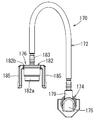
- FIG. 9 is a side view showing the leak passage forming member.
- the leak passage forming member 170 includes a leak tube 172, a first cap 174, and a second cap 176.
- the leak tube 172 and both caps 174 and 176 are made of resin.
- the leak tube 172 is made of a flexible tube.
- a series of leak passages 178 are formed by the leak tube 172 and the internal passages of the caps 174 and 176 (see FIGS. 7 and 8).
- the leak passage 178 is a passage for returning the pressurized fuel into the sub tank 54.
- the leak passage 178 corresponds to the “pressurized fuel return passage” in the present specification.
- the first cap 174 corresponds to the “upstream passage member” in the present specification.
- the second cap 176 corresponds to the “downstream passage member” in this specification.
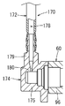
- FIG. 8 is a sectional view showing the tip of the discharge pipe of the pump case.
- the first cap 174 is formed in an elbow shape having a cylindrical cap portion 175 that closes the side end surface and a cylindrical connection port 179 that projects upward from the cap portion 175. .
- the cap portion 175 is formed so as to be connectable to the tip portion of the discharge pipe portion 96 of the pump case 60.
- the connection port 179 has an inner diameter smaller than the inner diameter of the cap portion 175.
- a throttle 180 that reduces the passage area is formed in the upstream end of the connection port 179.
- the throttle unit 180 limits the amount of pressurized fuel that leaks.
- One end of the leak tube 172 is press-fitted and connected to the connection port 179.
- the cap portion 175 is concentrically joined to the distal end portion of the discharge pipe portion 96 by welding.
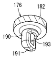
- the second cap 176 has a cap portion 182 and a connection port 183 concentrically.
- the cap portion 182 has a cylindrical tubular portion 182a and an end plate portion 182b that closes the upper end surface of the tubular portion 182a.
- the cap portion 182 is formed so that it can be fitted into the upper end opening of the guide tube portion 131 of the sub tank main body 66 and that the opening can be closed.
- the connection port 183 is formed in a cylindrical shape protruding upward from the central portion of the end plate portion 182b.
- the other end of the leak tube 172 is press-fitted and connected to the connection port 183.
- a pair of front and rear engaging pieces 185 having engaging holes 186 are formed on the outer peripheral portion of the end plate portion 182b of the cap portion 182.
- a pair of front and rear engaging protrusions 187 are formed on the outer surface of the upper end portion of the guide cylinder portion 131 of the sub tank main body 66.
- the second cap 176 is attached to the guide cylinder portion 131 of the sub tank body 66 by snap fitting. That is, by pressing the second cap 176 against the guide cylinder portion 131 from above, the engagement holes 186 are engaged with the engagement protrusions 187 by utilizing the elastic deformation of the engagement pieces 185.
- the tubular portion 182a of the cap portion 182 is fitted into the upper end opening of the guide tubular portion 131, and the upper end opening of the guide tubular portion 131 is opened by the end plate portion 182b. It is closed.
- FIG. 10 is a perspective view showing the diverting wall portion of the second cap. As shown in FIG. 10, the lower end opening of the extension cylinder 190 is covered by the diverting wall 191.
- a pressurizing fuel injection port 193 having a substantially vertically long rectangular shape is formed on one side of the extending tubular portion 190.
- the deflecting wall portion 191 is formed in a substantially 1/4 spherical shape.
- the turning wall portion 191 corresponds to the "wall member" in this specification.
- the discharge fuel pipe 124 is made of a flexible resin hose or the like.
- the first electrical connector portion 38 of the flange unit 22 and the electrical connector of the fuel pump 58 of the pump unit 26 are electrically connected via the first wire harness 126.
- the second electric connector portion 39 of the flange unit 22 and the gauge body 84 (see FIG. 3) of the pump unit 26 are electrically connected via the second wire harness 128.
- Both wire harnesses 126 and 128 are appropriately mounted on wiring hook portions integrally formed with the adjacent resin members.
- the fuel supply device 20 is in an extended state.
- the joint member 24 is suspended from the flange unit 22, and the pump unit 26 is suspended from the joint member 24. That is, the joint member 24 is lowered to the lowermost position (the most separated position) with respect to the flange unit 22. Further, the pump unit 26 is rotated (see the arrow Y1 in FIG. 3) to the right downward inclined state (see the chain double-dashed line 26 in FIG. 3) with respect to the joint member 24.
- the pump unit 26 is inserted into the opening 13 of the fuel tank 10 from above with the fuel supply device 20 in the extended state.
- the pump unit 26 is rotated with respect to the joint member 24 in a direction opposite to the suspension state (see arrow Y2 in FIG. 3) to be in a horizontal state and mounted on the bottom wall portion 12 of the fuel tank 10. (See FIGS. 2 and 3).
- a rotation limiting mechanism that limits the rotation of the pump unit 26 above the horizontal state is provided between the joint member 24 and the pump unit 26.
- the flange unit 22 is pushed down against the urging force of the spring 52, so that the canister portion 150 is fitted into the opening 13 of the fuel tank 10.
- the flange portion 34 of the flange main body 28 is fixed to the upper wall portion 11 of the fuel tank 10 through fixing means (not shown) such as fixing metal fittings and bolts (see FIGS. 2 and 3).
- fixing means such as fixing metal fittings and bolts (see FIGS. 2 and 3).
- the flange unit 22 closes the opening 13 of the fuel tank 10.
- a fuel supply pipe connected to the engine is connected to the fuel discharge port 37 of the flange unit 22. Further, external connectors are connected to the first electric connector portion 38 and the second electric connector portion 39, respectively. Further, the evaporation port 151 is connected to an evaporated fuel passage connected to the breather pipe of the fuel tank 10. Further, the atmosphere port 152 is open to the atmosphere. Further, the purge port 153 is connected to a purge passage connected to an intake passage of the engine.
- the pump unit 26 In the installed state of the fuel supply device 20 (see FIGS. 2 and 3), the pump unit 26 is held in a state of being pressed against the bottom wall portion 12 of the fuel tank 10 by the urging force of the spring 52. Further, the protrusion 81 of the cover member 68 abuts on the bottom wall portion 12 of the fuel tank 10, whereby the fuel flow between the cover member 68 and the bottom wall portion 12 is secured.
- the fuel tank 10 deforms, that is, expands and contracts due to changes in the tank internal pressure due to changes in temperature, changes in fuel amount, and the like.
- the distance between the upper wall portion 11 and the bottom wall portion 12 of the fuel tank 10 changes (increases or decreases).
- the flange unit 22 and the joint member 24 move in the vertical direction relatively to follow the change in the height of the fuel tank 10.
- the fuel pump 58 is driven by driving power from the outside. Then, the fuel from the inside of the fuel tank 10 via the cover member 68 and / or the fuel in the fuel storage space 79 of the pump unit 26 is sucked into the fuel pump 58 via the fuel filter 67 and pressurized.
- the pressurized fuel discharged from the fuel pump 58 flows into the regulator case 64 via the discharge pipe portion 96 of the pump case 60 and is pressure-controlled by the pressure regulator 62.
- the regulated pressurized fuel is supplied to the engine from the fuel discharge port 37 of the flange unit 22 via the discharge fuel pipe 124.
- the surplus fuel due to the pressure regulation of the pressure regulator 62 is discharged from the discharge pipe portion 118 of the regulator case 64 into the fuel receiving cylinder portion 71 of the sub tank body 66. Further, the evaporated fuel generated in the fuel tank 10 is introduced into the canister portion 150 from the evaporated fuel passage via the evaporation port 151. Further, the evaporated fuel in the canister portion 150 is purged into the intake passage via the purge passage by the intake negative pressure. Further, when the evaporated fuel in the canister unit 150 is purged, the atmosphere is introduced into the canister unit 150.
- a part of the pressurized fuel discharged from the fuel pump 58 to the fuel passage 133 in the discharge pipe portion 96 of the pump case 60 receives the fuel of the sub tank main body 66 through the leak passage 178 of the leak passage forming member 170. It is discharged into the cylindrical portion 71.
- the throttle portion 180 of the first cap 174 limits the amount of the pressurized fuel that leaks.
- the pressurized fuel that has flowed into the connecting port 183 of the second cap 176 and extends downwardly into the tubular portion 190 is deflected by approximately 90 ° by the deflection wall portion 191 and the pressurized fuel jet port 193.
- a concave arc-shaped wall portion of the tubular portion 182a facing the pressurized fuel jet port 193 is referred to as a facing wall 182c.
- the flow of the pressurized fuel ejected from the leak passage 178 is diverted by the diverting wall portion 191 of the second cap 176, so that the fuel filter 67 is applied to the upper surface of the filter member 75. Direct collision of pressurized fuel can be avoided. Thereby, the deformation of the filter member 75 of the fuel filter 67 due to the pressurized fuel ejected from the leak passage 178 can be suppressed.
- the deflecting wall portion 191 of the second cap 176 is not provided, the flow of the pressurized fuel ejected from the leak passage 178 is directly below the extending tubular portion 190 of the second cap 176. Are jetted out to directly collide with the upper surface of the filter member 75. Therefore, the upper surface of the filter member 75 may be deformed into a concave shape.
- the deflecting wall portion 191 in the extension tubular portion 190 by providing the deflecting wall portion 191 in the extension tubular portion 190, direct collision of the pressurized fuel with the upper surface of the filter member 75 is avoided, and the deformation of the filter member 75 is avoided. Can be suppressed.
- the pressurized fuel that has flowed through the leak passage 178 is diverted by the diverting wall portion 191 of the second cap 176 and ejected from the pressurized fuel ejection port 193. Thereby, direct collision of the pressurized fuel with the upper surface of the filter member 75 of the fuel filter 67 can be avoided.
- the second cap 176 is integrally formed with the deflecting wall portion 191 and the pressurized fuel jet port 193. Therefore, the structure of the second cap 176 having the diverting wall portion 191 and the pressurized fuel injection port 193 can be simplified and the cost can be reduced.
- the second cap 176 is provided with a concave arc-shaped facing wall 182c facing the pressurized fuel jet port 193. Therefore, the pressurized fuel ejected from the pressurized fuel ejection port 193 collides with the facing wall 182c of the second cap 176. As a result, the flow of the pressurized fuel can be changed and the flow velocity can be reduced.
- the amount of fuel leaking can be limited by the throttle portion 180 provided on the first cap 174.
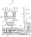
- FIG. 11 is a sectional view showing the peripheral portion of the pressure regulator.
- the sub-tank main body 66 of the sub-tank 54 is provided with a fuel outlet pipe portion 195 extending in the vertical direction.
- a fuel outlet passage 196 is formed in the fuel outlet pipe portion 195.
- the fuel outlet passage 196 is a branch passage branched from the fuel passage 133 and is a passage for returning the pressurized fuel into the sub tank 54.
- the fuel outlet passage 196 corresponds to the “pressurized fuel return passage” in the present specification.
- a pressure regulator 62 is fitted to the lower end of the fuel outlet passage 196.
- the pressure regulator 62 adjusts the pressure in the fuel derivation passage 196 to a predetermined pressure, and ejects the surplus fuel directly below the surplus fuel discharge port 62a.
- the pressure regulator 62 is normally submerged in the fuel stored in the fuel storage space 79.
- the fuel outlet pipe portion 195 corresponds to the “outlet passage forming member” in the present specification.
- a resin retaining member 198 for retaining the pressure regulator 62 is attached to the lower end of the fuel outlet passage 196 by snap fit.
- the retaining member 198 is formed in a bottomed cylindrical shape that covers the lower half of the pressure regulator 62 with a predetermined gap.
- a bottomed cylindrical deflection wall portion 200 facing the surplus fuel outlet 62a is formed.
- a plurality of (two in FIG. 11) pressurized fuel injection ports 202 are formed on the side wall of the diverting wall portion 200.
- the pressurized fuel ejected from the excess fuel discharge port 62a of the pressure regulator 62 is deflected by approximately 90 ° by the bottom wall of the deflection wall portion 200, and ejected laterally from the pressurized fuel ejection port 202 ( (See arrow in FIG. 11).
- the turning wall portion 200 corresponds to the "wall member" in this specification.
- the deflecting wall portion 200 of the retaining member 198 is cut off as an opening hole, the flow of the pressurized fuel ejected directly below from the surplus fuel discharge port 62a is the filter member 75. Directly hit the top surface of. Therefore, the upper surface of the filter member 75 may be deformed into a concave shape.
- the second embodiment by providing the deflecting wall portion 200 on the retaining member 198, direct collision of the pressurized fuel with the upper surface of the filter member 75 is avoided, and the filter member 75 is not deformed. Can be suppressed.
- the technology disclosed in the present specification has been described above with respect to the specific embodiment, the technology can be implemented in various other modes.
- the technology of the present disclosure is not limited to the fuel supply device 20 of a vehicle such as an automobile, but may be applied to other fuel supply devices.
- the wall member may be provided separately from the downstream passage member or the outlet passage forming member. In this case, the pressurized fuel ejected from the pressurized fuel ejection port collides with the wall member and is deflected.
- a part of the tubular portion 182a of the cap portion 182 of the second cap 176 is the facing wall 182c, but a dedicated facing wall other than the tubular portion 182a may be formed on the second cap 176.
- a first aspect is a fuel supply device for supplying fuel in a fuel tank to an internal combustion engine, wherein a fuel pump, a sub tank for storing the fuel, and a part of the pressurized fuel discharged from the fuel pump are
- the fuel tank includes a pressurized fuel return passage for returning to the inside of the sub tank, and a fuel filter provided at the bottom of the sub tank and having a bag-shaped filter member for filtering fuel sucked into the fuel pump.
- the fuel supply device includes a wall member that diverts the flow of the pressurized fuel so that the pressurized fuel ejected from the return passage does not collide with the filter member.
- the flow of the pressurized fuel ejected from the pressurized fuel return passage is diverted by the wall member, so that the direct collision of the pressurized fuel with the filter member of the fuel filter can be avoided. it can. Accordingly, the deformation of the filter member of the fuel filter due to the pressurized fuel ejected from the pressurized fuel return passage can be suppressed.
- a second aspect is the fuel supply device according to the first aspect, wherein the pressurized fuel return passage is a leak passage for leaking a part of the pressurized fuel discharged from the fuel pump.
- a downstream passage member that forms a downstream end portion of the downstream passage member, the wall member is formed on the downstream passage member, and the downstream passage member is deflected by the wall member.
- a pressurized fuel ejection port for ejecting the pressurized fuel is formed.
- the flow of the pressurized fuel that has flowed through the leak passage is diverted by the wall member of the downstream passage member, and is ejected from the pressurized fuel ejection port.
- direct collision of the pressurized fuel with the filter member of the fuel filter can be avoided.
- a third aspect is the fuel supply device according to the second aspect, wherein the wall member and the pressurized fuel injection port are integrally formed in the downstream passage member.
- the third aspect it is possible to simplify the structure of the downstream passage member having the wall member and the pressurized fuel ejection port, and reduce the cost.
- a fourth aspect is the fuel supply device according to the second or third aspect, wherein the downstream passage member includes a concave arcuate facing wall that faces the pressurized fuel jet port.
- the pressurized fuel ejected from the pressurized fuel ejection port collides with the facing wall of the downstream passage member. As a result, the flow of the pressurized fuel can be changed and the flow velocity can be reduced.
- a fifth aspect is the fuel supply device according to the first or second aspect, including an upstream passage member that forms an upstream end of the leak passage, and the upstream passage member leaks.
- a throttle portion that limits the amount of fuel is provided.
- the leaked fuel amount can be limited by the throttle portion provided in the upstream passage member.
- a sixth aspect is the fuel supply device according to the first aspect, wherein the pressurized fuel return passage is a fuel outlet passage for deriving a part of the pressurized fuel discharged from the fuel pump, A lead-out passage forming member that forms a lead-out passage is provided, and the lead-out passage forming member is provided with a pressure regulator that adjusts the pressure of the pressurized fuel and discharges excess pressurized fuel.
- a retaining member for retaining the pressure regulator is attached to the lead-out passage forming member, the wall member is formed in the retaining member, and the retaining member is formed by the wall member.
- a pressurized fuel ejection port for ejecting the deflected pressurized fuel is formed.
- the pressurized fuel ejected from the pressure regulator provided at the downstream end of the fuel outlet passage can be made to collide with the wall member of the retaining member. As a result, direct collision of the pressurized fuel with the filter member of the fuel filter can be avoided.
Landscapes
- Engineering & Computer Science (AREA)
- Chemical & Material Sciences (AREA)
- Combustion & Propulsion (AREA)
- Mechanical Engineering (AREA)
- General Engineering & Computer Science (AREA)
- Cooling, Air Intake And Gas Exhaust, And Fuel Tank Arrangements In Propulsion Units (AREA)
Abstract
Priority Applications (3)
| Application Number | Priority Date | Filing Date | Title |
|---|---|---|---|
| CN201980067892.8A CN112955642B (zh) | 2018-10-15 | 2019-10-01 | 燃料供给装置 |
| DE112019004616.0T DE112019004616B4 (de) | 2018-10-15 | 2019-10-01 | Kraftstoffzufuhrvorrichtung |
| US17/285,580 US11396856B2 (en) | 2018-10-15 | 2019-10-01 | Fuel supply device |
Applications Claiming Priority (2)
| Application Number | Priority Date | Filing Date | Title |
|---|---|---|---|
| JP2018-194220 | 2018-10-15 | ||
| JP2018194220A JP7083734B2 (ja) | 2018-10-15 | 2018-10-15 | 燃料供給装置 |
Publications (1)
| Publication Number | Publication Date |
|---|---|
| WO2020080098A1 true WO2020080098A1 (fr) | 2020-04-23 |
Family
ID=70283175
Family Applications (1)
| Application Number | Title | Priority Date | Filing Date |
|---|---|---|---|
| PCT/JP2019/038762 Ceased WO2020080098A1 (fr) | 2018-10-15 | 2019-10-01 | Dispositif de distribution de carburant |
Country Status (5)
| Country | Link |
|---|---|
| US (1) | US11396856B2 (fr) |
| JP (1) | JP7083734B2 (fr) |
| CN (1) | CN112955642B (fr) |
| DE (1) | DE112019004616B4 (fr) |
| WO (1) | WO2020080098A1 (fr) |
Cited By (1)
| Publication number | Priority date | Publication date | Assignee | Title |
|---|---|---|---|---|
| US11396856B2 (en) * | 2018-10-15 | 2022-07-26 | Aisan Kogyo Kabushiki Kaisha | Fuel supply device |
Families Citing this family (2)
| Publication number | Priority date | Publication date | Assignee | Title |
|---|---|---|---|---|
| WO2019189178A1 (fr) * | 2018-03-28 | 2019-10-03 | 愛三工業株式会社 | Bouchon de réservoir de carburant |
| JP2025181038A (ja) * | 2024-05-31 | 2025-12-11 | 愛三工業株式会社 | 燃料供給装置 |
Citations (5)
| Publication number | Priority date | Publication date | Assignee | Title |
|---|---|---|---|---|
| JPH05124445A (ja) * | 1991-10-31 | 1993-05-21 | Honda Motor Co Ltd | 車両用燃料供給装置 |
| WO2000000734A1 (fr) * | 1998-06-30 | 2000-01-06 | Mitsubishi Denki Kabushiki Kaisha | Dispositif d'alimentation en carburant pour vehicule |
| JP2006105148A (ja) * | 2004-10-07 | 2006-04-20 | Ti Group Automotive Systems Llc | 燃料フィルタの配置 |
| US20110174275A1 (en) * | 2010-01-15 | 2011-07-21 | Coavis | Fuel Supply System |
| JP2017040242A (ja) * | 2015-08-21 | 2017-02-23 | 株式会社豊田自動織機 | 車両用燃料供給装置 |
Family Cites Families (64)
| Publication number | Priority date | Publication date | Assignee | Title |
|---|---|---|---|---|
| US4869225A (en) * | 1987-10-26 | 1989-09-26 | Nippondenso Co., Ltd. | Fuel supply device for vehicles |
| US5482444A (en) * | 1994-09-06 | 1996-01-09 | General Motors Corporation | Vibration isolating mounting for an electric fuel pump |
| JP3820579B2 (ja) * | 1997-12-02 | 2006-09-13 | 株式会社デンソー | 燃料供給装置 |
| JP3283240B2 (ja) * | 1998-03-12 | 2002-05-20 | 東洋▲ろ▼機製造株式会社 | 燃料供給装置 |
| JP2002130061A (ja) * | 2000-10-20 | 2002-05-09 | Denso Corp | 蒸発燃料処理システム |
| JP3849512B2 (ja) * | 2001-12-06 | 2006-11-22 | 日産自動車株式会社 | 燃料タンクの燃料供給モジュール取付構造 |
| JP3941012B2 (ja) * | 2002-08-22 | 2007-07-04 | 株式会社デンソー | 燃料供給装置 |
| JP4051564B2 (ja) * | 2002-10-18 | 2008-02-27 | 株式会社デンソー | 燃料供給装置 |
| US6886541B2 (en) * | 2003-02-25 | 2005-05-03 | Denso International America, Inc. | Fuel pump module and method of assembly |
| US6694785B1 (en) * | 2003-05-08 | 2004-02-24 | Hui-Hua Hsieh | Automobile lock |
| JP2005201214A (ja) * | 2004-01-19 | 2005-07-28 | Mitsubishi Electric Corp | 燃料供給装置 |
| JP4179179B2 (ja) * | 2004-02-03 | 2008-11-12 | 株式会社デンソー | 燃料供給装置 |
| JP4257657B2 (ja) * | 2004-03-30 | 2009-04-22 | 株式会社デンソー | ポンプモジュール |
| JP4948775B2 (ja) * | 2004-06-14 | 2012-06-06 | 愛三工業株式会社 | 燃料供給装置 |
| US7124748B2 (en) * | 2004-12-16 | 2006-10-24 | Visteon Global Technologies, Inc. | Fuel delivery assembly for dual lobe fuel tank |
| JP4269340B2 (ja) * | 2004-12-27 | 2009-05-27 | 株式会社デンソー | 燃料供給装置 |
| JP4194589B2 (ja) * | 2005-08-31 | 2008-12-10 | 株式会社デンソー | 燃料供給装置 |
| US7237538B2 (en) * | 2005-09-09 | 2007-07-03 | Ti Automotive Fuel Systems Sas | Modular fuel delivery assembly |
| JP2007231907A (ja) * | 2006-03-03 | 2007-09-13 | Denso Corp | 燃料供給装置 |
| DE102008040390A1 (de) * | 2007-07-23 | 2009-01-29 | Denso Corp., Kariya-shi | Kraftstoffzufuhrsystem |
| JP4661947B2 (ja) | 2008-03-21 | 2011-03-30 | 株式会社デンソー | ポンプモジュール |
| JP4673915B2 (ja) * | 2008-12-02 | 2011-04-20 | 本田技研工業株式会社 | 燃料タンクの波消し構造 |
| JP2011122563A (ja) * | 2009-12-14 | 2011-06-23 | Denso Corp | 燃料ポンプ |
| KR101138206B1 (ko) * | 2010-01-12 | 2012-05-10 | 주식회사 코아비스 | 연료펌프모듈 |
| JP5585251B2 (ja) | 2010-07-08 | 2014-09-10 | 株式会社デンソー | フィルタ装置 |
| DE102011082418A1 (de) * | 2010-09-13 | 2012-03-15 | Denso Corporation | Kraftstoffzufuhrgerät |
| JP6192939B2 (ja) * | 2013-01-22 | 2017-09-06 | 愛三工業株式会社 | 燃料タンク内部品の結合構造 |
| KR101340914B1 (ko) * | 2013-05-23 | 2013-12-13 | 주식회사 코아비스 | 스트레이너 및 이를 포함하는 연료펌프모듈 |
| US9556837B2 (en) * | 2014-05-13 | 2017-01-31 | Robert Bosch Gmbh | Spring loaded component mounting within fuel tank |
| JP6138369B2 (ja) * | 2014-06-13 | 2017-05-31 | 三菱電機株式会社 | 燃料供給装置 |
| JP6258157B2 (ja) * | 2014-08-26 | 2018-01-10 | 愛三工業株式会社 | 燃料供給装置 |
| JP6258158B2 (ja) * | 2014-08-26 | 2018-01-10 | 愛三工業株式会社 | 燃料供給装置 |
| JP6215155B2 (ja) * | 2014-08-26 | 2017-10-18 | 愛三工業株式会社 | 燃料供給装置 |
| JP6282558B2 (ja) * | 2014-08-26 | 2018-02-21 | 愛三工業株式会社 | 燃料供給装置 |
| US9982640B2 (en) * | 2014-08-27 | 2018-05-29 | Robert Bosch Gmbh | Fuel pump module with replaceable filter unit |
| JP6365180B2 (ja) | 2014-09-25 | 2018-08-01 | 株式会社デンソー | リリーフバルブ及び燃料供給システム |
| US9539893B2 (en) * | 2014-09-29 | 2017-01-10 | Spectra Premium Industries Inc. | Fuel delivery module for low-profile fuel tank |
| JP6301234B2 (ja) * | 2014-11-06 | 2018-03-28 | 愛三工業株式会社 | 燃料供給装置 |
| JP6331980B2 (ja) * | 2014-11-06 | 2018-05-30 | 株式会社デンソー | 燃料供給装置 |
| JP2016151224A (ja) * | 2015-02-17 | 2016-08-22 | 京三電機株式会社 | 燃料供給装置 |
| JP6451602B2 (ja) * | 2015-11-13 | 2019-01-16 | 株式会社デンソー | 燃料供給装置 |
| JP6599248B2 (ja) * | 2016-01-21 | 2019-10-30 | 愛三工業株式会社 | 燃料供給装置 |
| JP6821305B2 (ja) * | 2016-02-19 | 2021-01-27 | 愛三工業株式会社 | 燃料タンク用蓋部材 |
| JP6695707B2 (ja) * | 2016-02-19 | 2020-05-20 | 愛三工業株式会社 | 燃料供給装置 |
| DE112017000895B4 (de) * | 2016-02-19 | 2022-03-10 | Aisan Kogyo Kabushiki Kaisha | Kraftstoffzufuhrvorrichtung mit Siebbauteil |
| JP6390681B2 (ja) * | 2016-03-14 | 2018-09-19 | 株式会社デンソー | 燃料供給装置 |
| JP6424854B2 (ja) * | 2016-03-18 | 2018-11-21 | 株式会社デンソー | 燃料供給装置及びその製造方法 |
| JP6414113B2 (ja) * | 2016-03-24 | 2018-10-31 | 株式会社デンソー | 燃料供給装置 |
| JP6387998B2 (ja) * | 2016-03-30 | 2018-09-12 | 株式会社デンソー | プレッシャレギュレータ及び燃料供給装置 |
| DE102016206478A1 (de) * | 2016-04-18 | 2017-10-19 | Robert Bosch Gmbh | Vorrichtung und Verfahren zur Veränderung eines Drucks in einem Kraftstoffbehälter |
| JP6388001B2 (ja) * | 2016-04-20 | 2018-09-12 | 株式会社デンソー | 燃料供給装置 |
| JP6394636B2 (ja) * | 2016-04-28 | 2018-09-26 | 株式会社デンソー | 燃料供給装置 |
| US10247597B2 (en) * | 2016-07-28 | 2019-04-02 | Nissan North America, Inc. | Fuel pump assembly |
| US10215614B2 (en) * | 2016-07-28 | 2019-02-26 | Nissan North America, Inc. | Fuel sender assembly |
| JP6696356B2 (ja) * | 2016-08-26 | 2020-05-20 | 株式会社デンソー | フィルタモジュール、および、これを用いた燃料ポンプモジュール |
| JP6662757B2 (ja) * | 2016-11-18 | 2020-03-11 | 株式会社デンソー | 燃料供給装置、並びに、燃料供給装置の取り付け及び取り外し方法 |
| KR102113741B1 (ko) * | 2017-11-06 | 2020-05-21 | 가부시키가이샤 덴소 | 연료 펌프 모듈 |
| DE102018201117B3 (de) * | 2018-01-24 | 2019-07-04 | Ford Global Technologies, Llc | Baugruppe für ein Fahrzeug, insbesondere Hybridelektrofahrzeug und Fahrzeug, insbesondere Hybridelektrofahrzeug |
| WO2019189178A1 (fr) * | 2018-03-28 | 2019-10-03 | 愛三工業株式会社 | Bouchon de réservoir de carburant |
| JP6918733B2 (ja) * | 2018-03-28 | 2021-08-11 | 愛三工業株式会社 | 燃料タンク用蓋 |
| JP6968738B2 (ja) * | 2018-03-28 | 2021-11-17 | 愛三工業株式会社 | 燃料タンク用蓋 |
| JP6992669B2 (ja) * | 2018-04-27 | 2022-01-13 | 株式会社デンソー | 燃料供給装置 |
| US10634102B2 (en) * | 2018-09-06 | 2020-04-28 | Trico Group, LLC | Fuel pump assembly |
| JP7083734B2 (ja) * | 2018-10-15 | 2022-06-13 | 愛三工業株式会社 | 燃料供給装置 |
-
2018
- 2018-10-15 JP JP2018194220A patent/JP7083734B2/ja active Active
-
2019
- 2019-10-01 US US17/285,580 patent/US11396856B2/en active Active
- 2019-10-01 WO PCT/JP2019/038762 patent/WO2020080098A1/fr not_active Ceased
- 2019-10-01 CN CN201980067892.8A patent/CN112955642B/zh active Active
- 2019-10-01 DE DE112019004616.0T patent/DE112019004616B4/de active Active
Patent Citations (5)
| Publication number | Priority date | Publication date | Assignee | Title |
|---|---|---|---|---|
| JPH05124445A (ja) * | 1991-10-31 | 1993-05-21 | Honda Motor Co Ltd | 車両用燃料供給装置 |
| WO2000000734A1 (fr) * | 1998-06-30 | 2000-01-06 | Mitsubishi Denki Kabushiki Kaisha | Dispositif d'alimentation en carburant pour vehicule |
| JP2006105148A (ja) * | 2004-10-07 | 2006-04-20 | Ti Group Automotive Systems Llc | 燃料フィルタの配置 |
| US20110174275A1 (en) * | 2010-01-15 | 2011-07-21 | Coavis | Fuel Supply System |
| JP2017040242A (ja) * | 2015-08-21 | 2017-02-23 | 株式会社豊田自動織機 | 車両用燃料供給装置 |
Cited By (1)
| Publication number | Priority date | Publication date | Assignee | Title |
|---|---|---|---|---|
| US11396856B2 (en) * | 2018-10-15 | 2022-07-26 | Aisan Kogyo Kabushiki Kaisha | Fuel supply device |
Also Published As
| Publication number | Publication date |
|---|---|
| CN112955642B (zh) | 2023-01-24 |
| US20210396196A1 (en) | 2021-12-23 |
| DE112019004616B4 (de) | 2025-12-18 |
| CN112955642A (zh) | 2021-06-11 |
| JP7083734B2 (ja) | 2022-06-13 |
| JP2020063671A (ja) | 2020-04-23 |
| DE112019004616T5 (de) | 2021-06-10 |
| US11396856B2 (en) | 2022-07-26 |
Similar Documents
| Publication | Publication Date | Title |
|---|---|---|
| JP6644815B2 (ja) | 燃料供給装置 | |
| US5875816A (en) | Fuel feeding module with integrated fuel fine filter | |
| US11118549B2 (en) | Cover for fuel tank | |
| WO2020080098A1 (fr) | Dispositif de distribution de carburant | |
| CN108603468A (zh) | 燃料箱用盖构件 | |
| JP2010121560A (ja) | 燃料供給装置 | |
| WO2018061558A1 (fr) | Ensemble pompe | |
| JP6869917B2 (ja) | 燃料供給装置 | |
| JP6882223B2 (ja) | 燃料供給装置 | |
| JP6695789B2 (ja) | 燃料供給装置 | |
| EP3263387A1 (fr) | Système et procédé pour clapet de refoulement résistant aux vibrations | |
| JP6953344B2 (ja) | 燃料タンク用蓋 | |
| JP2021173245A (ja) | 燃料供給装置 | |
| JP2645957B2 (ja) | 自動車用燃料タンク | |
| JP6907145B2 (ja) | 燃料供給装置 | |
| WO2021006009A1 (fr) | Couvercle pour réservoir de carburant | |
| WO2019188032A1 (fr) | Dispositif d'alimentation en carburant | |
| US11125196B2 (en) | Bottom mount fuel pump assembly | |
| JP2020063734A (ja) | 燃料タンク内支柱の取付構造 | |
| JP2004137986A (ja) | ポンプモジュール | |
| JP2020063672A (ja) | 燃料タンク用サブタンク | |
| JP6815298B2 (ja) | 燃料供給装置 | |
| JP2020197182A (ja) | 燃料供給装置 | |
| JP4682960B2 (ja) | 燃料ポンプモジュール |
Legal Events
| Date | Code | Title | Description |
|---|---|---|---|
| 121 | Ep: the epo has been informed by wipo that ep was designated in this application |
Ref document number: 19873383 Country of ref document: EP Kind code of ref document: A1 |
|
| WWE | Wipo information: entry into national phase |
Ref document number: 112019004616 Country of ref document: DE |
|
| WWP | Wipo information: published in national office |
Ref document number: 112019004616 Country of ref document: DE |
|
| 122 | Ep: pct application non-entry in european phase |
Ref document number: 19873383 Country of ref document: EP Kind code of ref document: A1 |
|
| WWG | Wipo information: grant in national office |
Ref document number: 112019004616 Country of ref document: DE |